Removal and Installation
ZOOM
SIZED FOR PRINT
Page 1 of 9
REMOVAL
1.
REMOVE HOOD HINT:
¡
At the time of installation, please refer to the following item.
¡
Adjust the hood.
2.
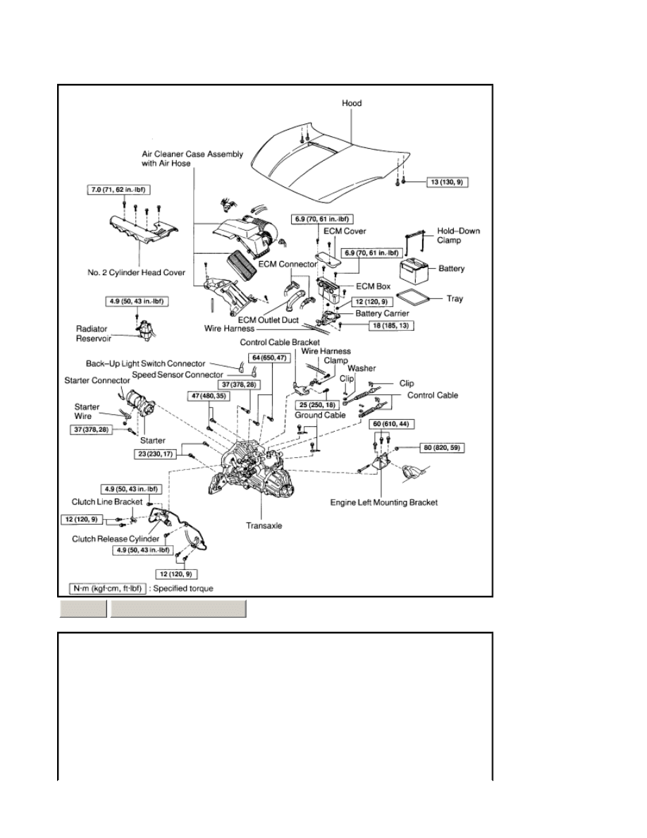
REMOVE No.2 CYLINDER HEAD COVER Remove the 4 bolts and No.2 cylinder head cover. Torque: 7.0 Nm (71
ZOOM
SIZED FOR PRINT
Page 2 of 9
kgf-cm, 62 inch lbs.)
3.
DISCONNECT RADIATOR RESERVOIR Remove the bolt and disconnect the radiator reservoir. Torque: 4.9 Nm
(50 kgf-cm, 43 inch lbs.)
4.
REMOVE BATTERY
5.
REMOVE AIR CLEANER
CASE
ASSEMBLY WITH AIR HOSE AND ECM BOX
6.
DISCONNECT
CONTROL CABLE
7.
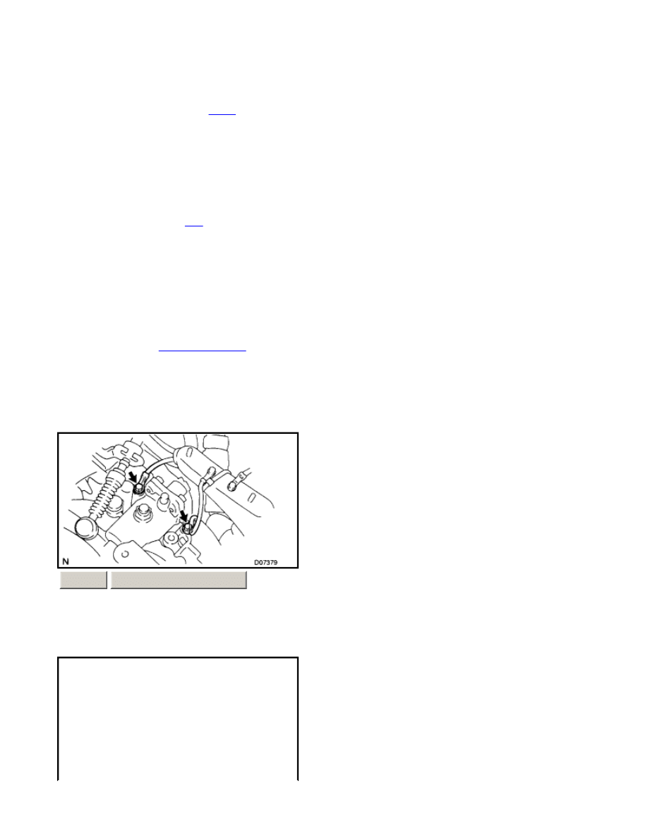
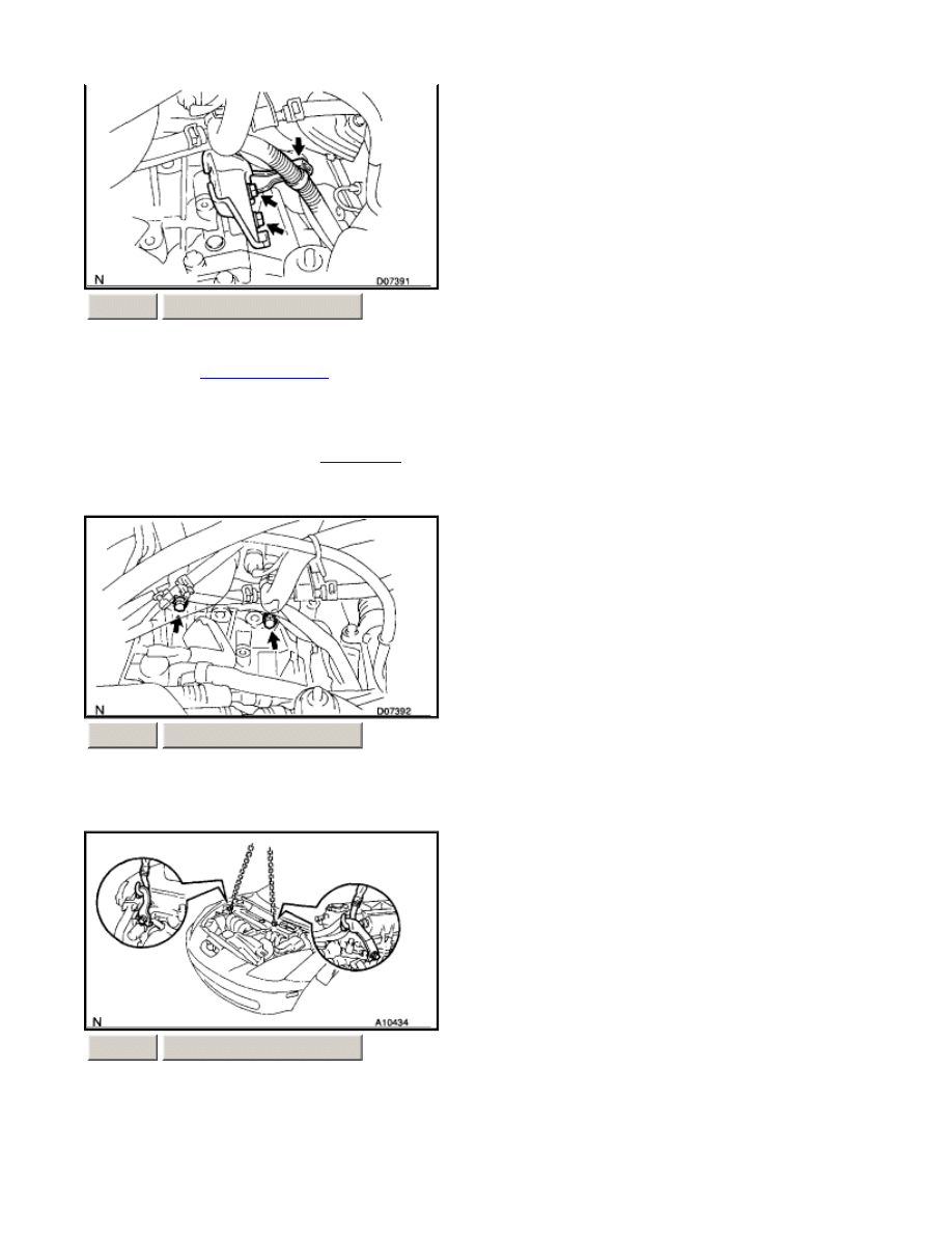
DISCONNECT GROUND CABLE Remove the 2 set bolts of the 2 ground cables from the transaxle.
8.
DISCONNECT SPEED SENSOR AND BACK-UP LIGHT SWITCH CONNECTORS
a)
Remove the 2 bolts and ECM cover.
Torque: 6.9 Nm (70 kgf-cm, 61 inch lbs.)
b)
Disconnect the ECM connectors from the ECM.
c)
Remove the ECM outlet duct.
d)
Remove the air cleaner
case
assembly with the air hose.
e)
Remove the 3 bolts and ECM box.
Torque: 6.9 Nm (70 kgf-cm, 61 inch lbs.)
f)
Disconnect the wire harness, and remove the 2 nuts, bolt and battery carrier.
Torque:
Bolt: 18 Nm (185 kgf-cm, 13 ft. lbs.)
Nut: 12 Nm (120 kgf-cm, 9 ft. lbs.)
a)
Remove the 2 clips and washers.
b)
Remove the 2 clips and disconnect the control cables from the transaxle.
ZOOM
SIZED FOR PRINT
Page 3 of 9
9.
DISCONNECT
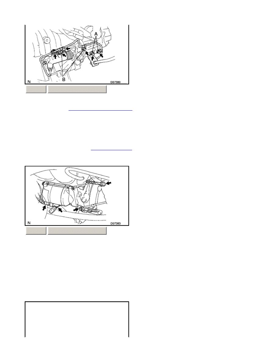
CLUTCH RELEASE CYLINDER
10.
REMOVE STARTER
ZOOM
SIZED FOR PRINT
a)
Remove the 4 set bolts of the clutch line.
Torque:
Bolt A: 12 Nm (120 kgf-cm, 9 ft. lbs.)
Bolt B: 4.9 Nm (50 kgf-cm, 43 inch lbs.)
b)
Remove the 2 set bolts of the
clutch release cylinder
and clutch line bracket.
Torque: 12 Nm (120 kgf-cm, 9 ft. lbs.)
ZOOM
SIZED FOR PRINT
a)
Disconnect the starter connector.
b)
Remove the nut and disconnect the starter wire.
c)
Remove the 2 bolts and starter.
Torque:37 Nm (378 kgf-cm, 28 ft. lbs.)
Page 4 of 9
11.
REMOVE
CONTROL CABLE
BRACKET
12.
REMOVE 2 TRANSAXLE UPPER SIDE MOUNTING BOLTS Torque: 64 Nm (650 kgf-cm, 47 ft. lbs.)
13.
ATTACH ENGINE SLING DEVICE TO ENGINE HANGER
ZOOM
SIZED FOR PRINT
a)
Disconnect the wire harness from the clamp.
b)
Remove the 2 bolts, clamp and
control cable
bracket from the transaxle.
Torque:25 Nm (250 kgf-cm, 18 ft. lbs.)
ZOOM
SIZED FOR PRINT
ZOOM
SIZED FOR PRINT
Page 5 of 9
CAUTION: Do not attempt to hang the engine by hooking the chain to any other part.
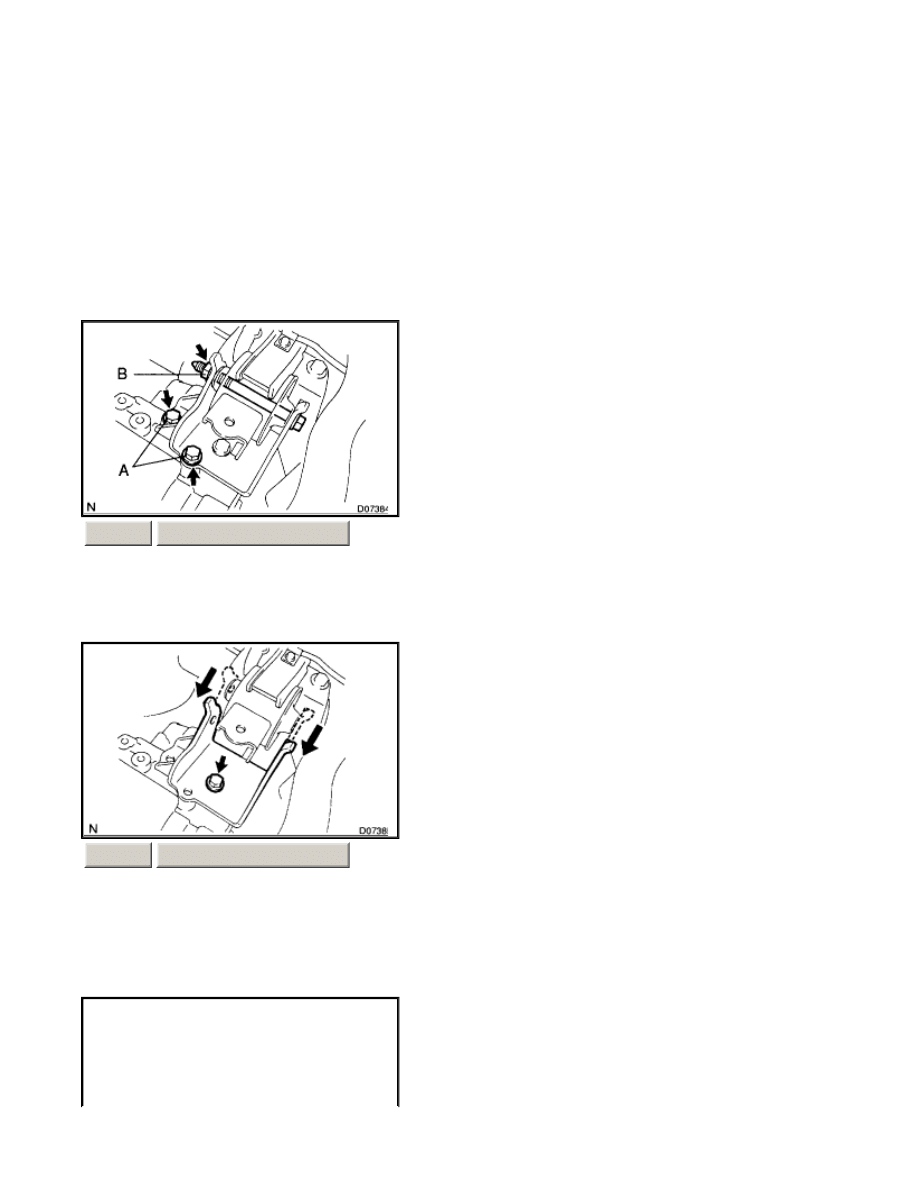
14.
REMOVE ENGINE LEFT MOUNTING BRACKET 3 SET BOLTS AND NUT Torque: Bolt A: 60 Nm (610 kgf-
cm, 44 ft. lbs.) Nut B: 80 Nm (820 kgf-cm, 59 ft. lbs.)
15.
REMOVE ENGINE LEFT MOUNTING BRACKET Lower the transaxle side, and remove the bolt and engine left
mounting bracket. Torque: 60 Nm (610 kgf-cm, 44 ft. lbs.)
16.
RAISE VEHICLE CAUTION: Make sure that the vehicle is securely supported.
17.
REMOVE CENTER, LH AND RH ENGINE UNDER COVERS
a)
Disconnect the 2 PCV hoses.
b)
Install the No.1 and No.2 engine hangers in the correct direction.
Parts No.:
No.1 engine hanger: 12281-88600
No.2 engine hanger: 12282-88600
Bolt: 91512-61020
Torque: 38 Nm (387 kgf-cm, 28 ft. lbs.)
c)
Attach the engine chain hoist to the engine hangers.
ZOOM
SIZED FOR PRINT
ZOOM
SIZED FOR PRINT
Page 6 of 9
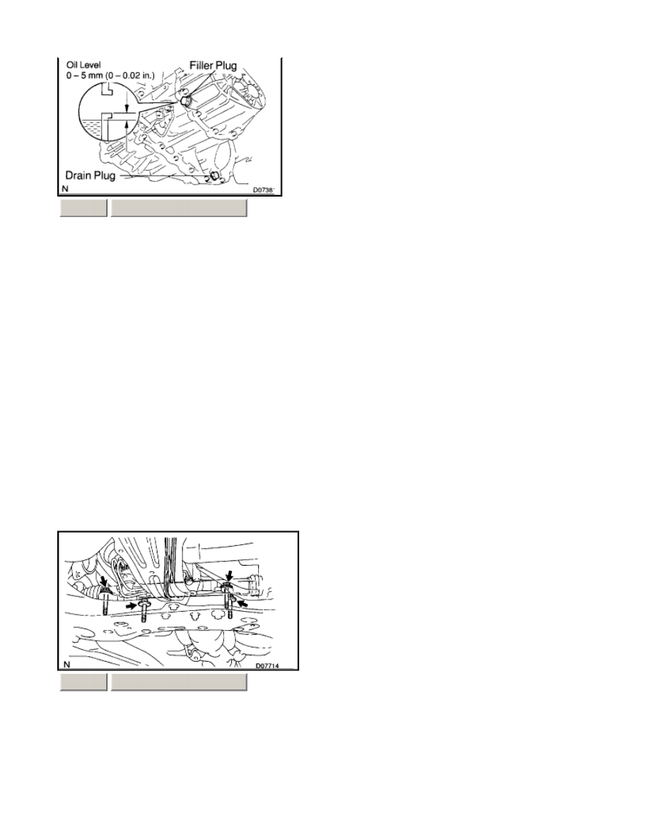
18.
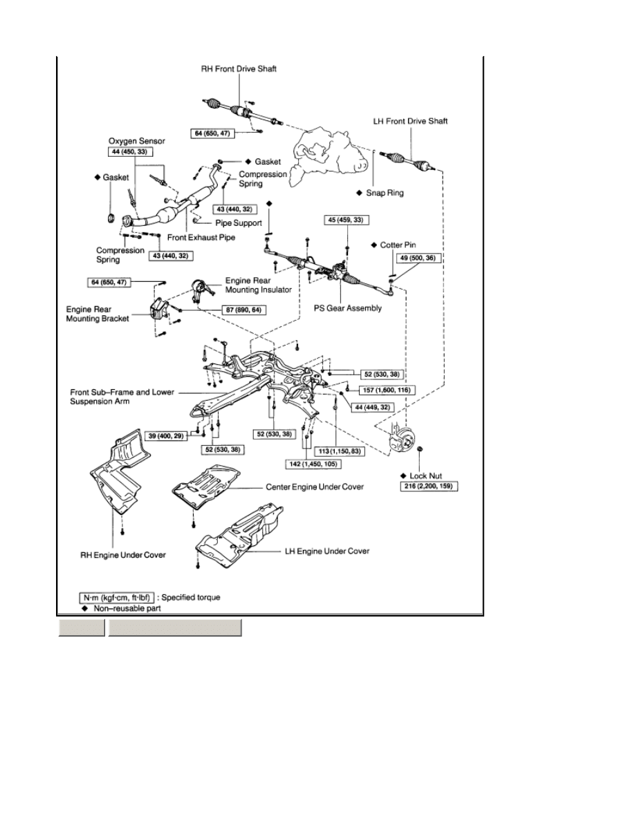
DRAIN TRANSAXLE OIL Oil grade: API GL-4 or GL-5 Viscosity: SAE 75W-90 Capacity: 2.3 liters (2.4 US qts,
2.0 Imp. qts) Torque: 39 Nm (400 kgf-cm, 29 ft. lbs.)
19.
REMOVE LH AND RH FRONT DRIVE SHAFTS
20.
REMOVE FRONT EXHAUST PIPE
HINT:
l
At the time of installation, please refer to the following items.
l
Before installing the heated oxygen sensor, twist the sensor wire counterclockwise 3 and 1/2 turns.
l
After installing the heated oxygen sensor, check that the sensor wire is not twisted. If it is twisted, remove the heated
oxygen sensor and reinstall it.
21.
REMOVE FRONT SUB-FRAME AND LOWER SUSPENSION ARM
ZOOM
SIZED FOR PRINT
a)
Disconnect the 2 heated oxygen sensors.
Torque: 44 Nm (450 kgf-cm, 33 ft. lbs.)
b)
Remove the 4 bolts, compression springs and 2 gaskets.
Torque: 43 Nm (440 kgf-cm, 32 ft. lbs.)
c)
Disconnect the front exhaust pipe from the pipe supports and remove it.
ZOOM
SIZED FOR PRINT
a)
Tie the PS gear assembly to the proper position with a code or an equivalent to suspend the assembly securely.
Page 7 of 9
22.
REMOVE ENGINE REAR MOUNTING INSULATOR AND BRACKET
23.
JACK UP TRANSAXLE SLIGHTLY Using a transmission jack, support the transaxle.
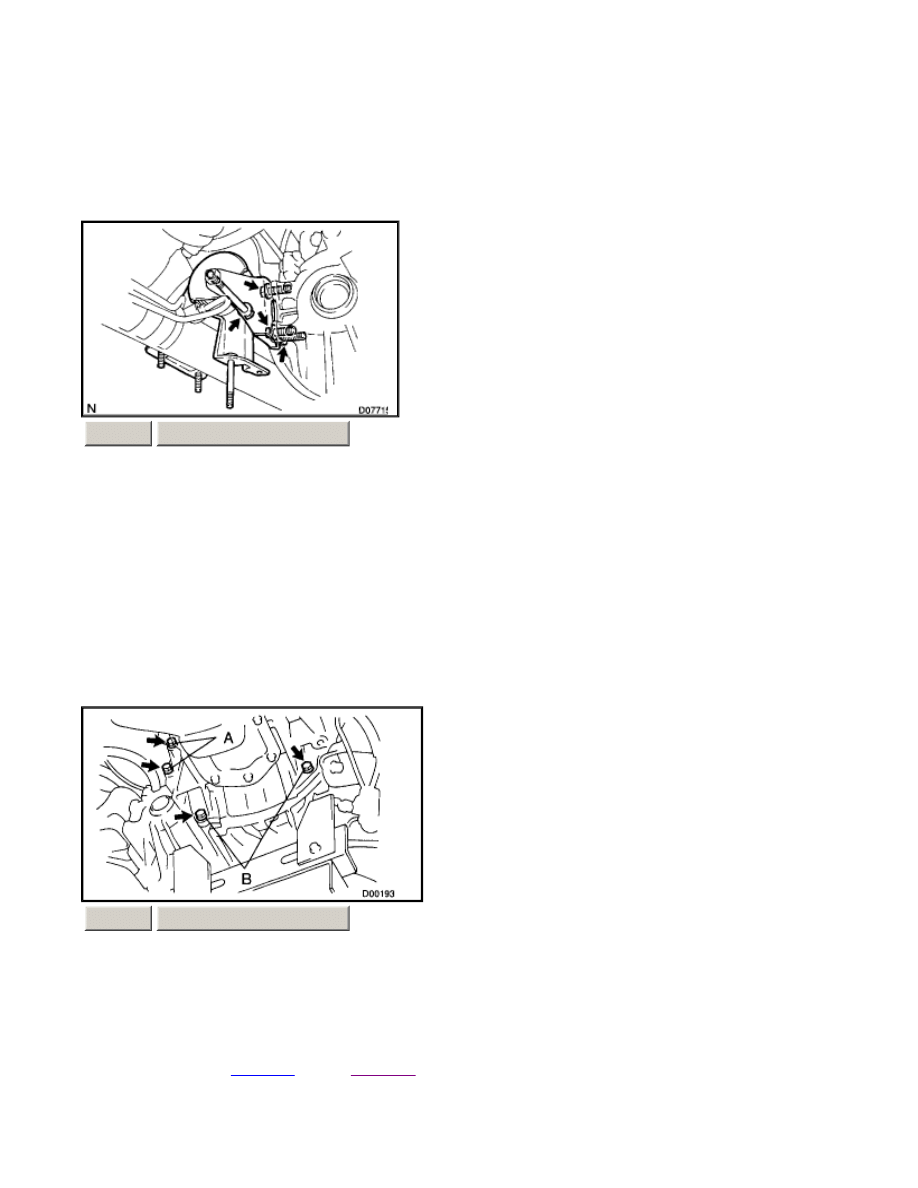
24.
REMOVE 4 TRANSAXLE LOWER SIDE MOUNTING BOLTS Torque: Bolt A: 47 Nm (480 kgf-cm, 35 ft. lbs.)
Bolt B:23 Nm (230 kgf-cm, 17 ft. lbs.)
25.
REMOVE TRANSAXLE Lower the engine left side and remove the transaxle from the engine. HINT: .
¡
At the time of installation, please refer to the following items.
¡
Align the
input shaft
with the
clutch disc
and install the transaxle to the engine.
¡
Temporarily tighten the transaxle mounting bolts.
b)
Remove the 4 set bolts of the PS gear assembly.
Torque: 45 Nm (459 kgf-cm, 33 ft. lbs.)
c)
Disconnect the LH and RH stabilizer bar links from the shock absorber.
d)
Remove the front sub-frame and lower suspension arm.
ZOOM
SIZED FOR PRINT
a)
Remove the bolt and engine rear mounting insulator.
Torque: 87 Nm (890 kgf-cm, 64 ft. lbs.)
b)
Remove the 3 bolts and engine rear mounting bracket.
Torque: 64 Nm (650 kgf-cm, 47 ft. lbs.)
ZOOM
SIZED FOR PRINT
Page 8 of 9

INSTALLATION
Installation is in the reverse order of removal.
HINT: After installation, check and inspect items as follows.
l
Front wheel alignment.
l
Do the road test.
Page 9 of 9
Wyszukiwarka
Podobne podstrony:
ARTICLE MANUAL TRANSAXLE ASSMEBLY
06 MANUAL TRANSAXLE (C153)(1)
13 manual transaxle
M33b Manual Transaxle Drive Axle
ARTICLE TRANNY AUTO DISASSEMBLE PART2
ARTICLE ELECTRICAL ALTERNATOR DISASSEMBLY
ARTICLE TRANNY AUTO DISASSEMBLE PART1
M35b Five Speed Manual Transaxle
06 MANUAL TRANSAXLE (C153)(1)
06 MANUAL TRANSAXLE (C153)(1)
FIVE SPEED MANUAL TRANSAXLE SECTION 5B 91
więcej podobnych podstron