
LUBRICATION
AND
M A I N T E N A N C E
Return To Main Table of Contents
SCHEDULED MAINTENANCE TABLE . . . . . . . . . . . . . . . . . . 2
RECOMMENDED LUBRICANTS AND CAPACITIES . . . . 6
MAINTENANCE SERVICE . . . . . . . . . . . . . . . . . . . . . . . . . . . . . . 7
SCHEDULED MAINTENANCE TABLE
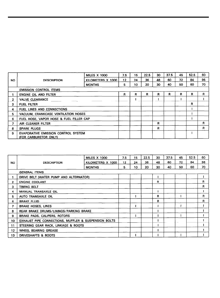
SCHEDULED MAINTENANCE TABLE (FOR U.S.A.)
RECOMMENDED CUSTOMER MAINTENANCE
The following maintenance services must be performed to assure good emission control and performance. Keep
receipts for all vehicle emission services to protect your emission warranty.
Where both mileage and time are shown, the frequency of service is determined by whichever occurs first.
R : REPLACE
I : INSPECT, AFTER INSPECTION, CLEAN, ADJUST, REPAIR OR REPLACE IF NECESSARY
1 0 - 2
SCHEDULED MAINTENANCE TABLE
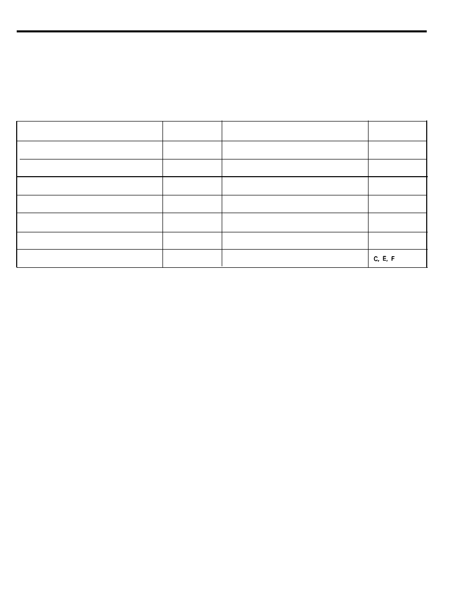
MAINTENANCE UNDER SEVERE USAGE CONDITIONS (FOR U.S.A.)
The following items must be serviced more frequently on vehicles normally used under severe driving conditions.
Refer to the chart below for the appropriate maintenance intervals.
I : INSPECT, CORRECT OR REPLACE IF NECESSARY
R : REPLACE
MAINTENANCE ITEM
ENGINE OIL AND FILTER
MAINTENANCE
MAINTENANCE INTERVALS
DRIVING
OPERATION
CONDITION
R
Every 3,000 miles (4,800 km)
or 3 months
A, B, C, F
AIR CLEANER FILTER
R
More frequently
C, E
SPARK PLUGS
R
Every 24,000 miles (40,000 km)
or 18 months
B
BRAKE PADS, CALIPERS, ROTORS
I
More frequently
C, D, G
REAR BRAKE DRUMS/LININGS
I
More frequently
C, D, G
I
STEERING GEAR RACK LINKAGE
& BOOTS
I
Every 7,500 miles (12,000 km)
or 6 months
C, D, E, F
I
DRIVESHAFT & BOOTS
I
Every 7,500 miles (12,000 km)
or 6 months
SEVERE DRIVING CONDITIONS
A-Repeated short distance driving
B-Extensive idling
C-Driving in dusty conditions
D-Driving in areas using salt or other corrosive materials or in very cold weather
E-Driving in sandy areas
F-More than 50% driving in heavy city traffic during hot weather above 90
o
F (32°C)
G-Driving in mountainous areas
1 0 - 3
SCHEDULED MAINTENANCE TABLE
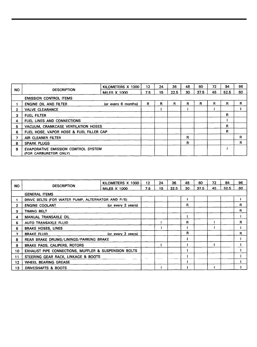
SCHEDULED MAINTENANCE TABLE (FOR CANADA)
RECOMMENDED CUSTOMER MAINTENANCE
The following maintenance services must be performed to assure good emission control and performance. Keep
receipts for all vehicle emission services to protect your emission warranty.
Where both mileage and time are shown, the frequency of service is determined by whichever occurs first.
R : REPLACE
I : INSPECT, AFTER INSPECTION, CLEAN, ADJUST, REPAIR OR REPLACE IF NECESSARY
1 0 - 4
SCHEDULED MAINTENANCE TABLE
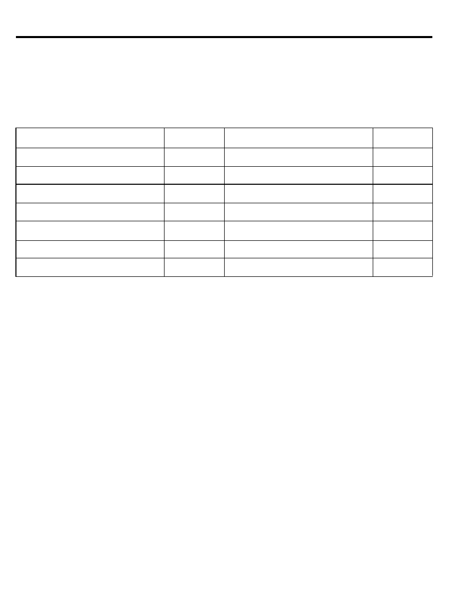
MAINTENANCE UNDER SEVERE USAGE CONDITIONS (FOR CANADA)
The following items must be serviced more frequently on vehicles normally used under severe driving conditions.
Refer to the chart below for the appropriate maintenance intervals.
I : INSPECT, CORRECT OR REPLACE IF NECESSARY
R : REPLACE
MAINTENANCE ITEM
ENGINE OIL AND FILTER
MAINTENANCE
MAINTENANCE INTERVALS
DRIVING
OPERATION
CONDITION
R
Every 5,000 km (3,000 miles)
or 3 months
A, B, C, F
AIR CLEANER FILTER
R
More frequently
C, E
SPARK PLUGS
R
Every 40,000 km (24,000 miles)
or 18 months
BRAKE PADS, CALIPERS, ROTORS
I
More frequently
C, D, G
REAR BRAKE DRUMS/LININGS
I
More frequently
C, D, G
STEERING GEAR RACK LINKAGE
& BOOTS
I
Every 12,000 km (7,500 miles)
or 6 months
C, D, E, F
DRIVESHAFT & BOOTS
I
I
Every 12,000 km (7,500 miles)
or 6 months
C, E, F
SEVERE DRIVING CONDITIONS
A-Repeated short distance driving
B-Extensive idling
C-Driving in dusty conditions
D-Driving in areas using salt or other corrosive materials or in very cold weather
E-Driving in sandy areas
F-More than 50% driving in heavy city traffic during hot weather above 90
o
F (32°C)
G-Driving in mountainous areas
1 0 - 5
RECOMMENDED LUBRICANTS AND CAPACITIES
RECOMMENDED LUBRICANTS AND CAPACITIES
RECOMMENDED LUBRICANTS
Parts
Engine oil
Manual transaxle
Automatic transaxle
Brake
Rear wheel bearing
Cooling system
Transaxle linkage, parking
brake cable mechanism, hood
lock and hook, door latch, seat
adjuster, trunk latch, door hinges,
trunk hinges
Door hinges, trunk hinges
Power steering
Specifications
API classification SF or SF/CC
For further details, refer to
or SG
SAE viscosity number
API classification GL-4
SAE grade number:
SAE 75W-85W
GENUINE HYUNDAI AUTOMATIC
TRANSMISSION FLUID, MOPAR
ATF PLUS TYPE 7176 OR DIAMOND
ATF SP.
Conforming to DOT 3 or equivalent
Multi-purpose grease NLGI
Grade #2, EP
High quality ethylene glycol
Multipurpose grease NLGI
Grade #2
Engine oil
DEXRON
®
II type
Remarks
MOPAR ATF PLUS TYPE 7176
is recommended lubricant
Concentration level 50%
LUBRICANTS CAPACITIES
Description
Capacities
Remarks
Engine oil
Oil pan
Oil filter
Total
Cooling system
Manual transaxle
Automatic transaxle
Power steering
3.0 lit (3.17 U.S. qts., 2.64 Imp.qts.)
0.4 lit (0.42 U.S. qts., 0.35 Imp.qts.)
3.4 lit (3.59 U.S. qts., 2.99 Imp.qts.)
5.3 lit (5.6 U.S. qts., 5.0 Imp.qts.)
1.8 lit (1.9 U.S. qts., 1.6 Imp.qts.) (KM201)
1.7 lit (1.8 U.S. qts., 1.5 Imp.qts.) (KM200)
6.1 lit (6.4 U.S. qts., 5.4 Imp.qts.)
0.9 lit (0.95 U.S. qts.)
1 0 - 6
MAINTENANCE SERVICE
MAINTENANCE SERVICE
ENGINE OIL
Always use lubricants which conform to the requirements of the
API classification “For Service SF or For Service SF/CC or For
Service SG” when available, and have proper SAE grade number
for the expected temperature range.
Refer to page 20-11, 20-12.
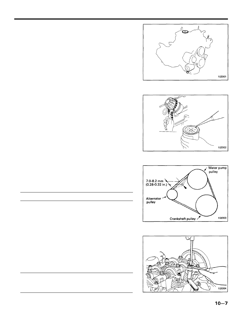
ENGINE OIL FILTER
1. Remove the oil filter with a suitable wrench.
2.
For installation, apply engine oil to the oil filter gasket and
tighten the oil filter fully by hand.
NOTE
Be sure gasket sealing surface on engine block is clean and
free of debris.
Be sure to remove old gasket from block prior to installing
new filter.
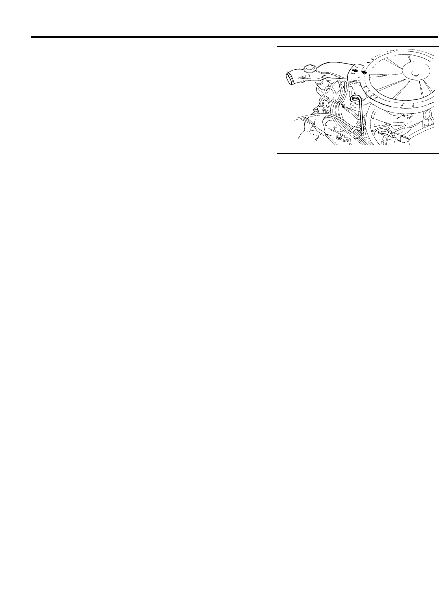
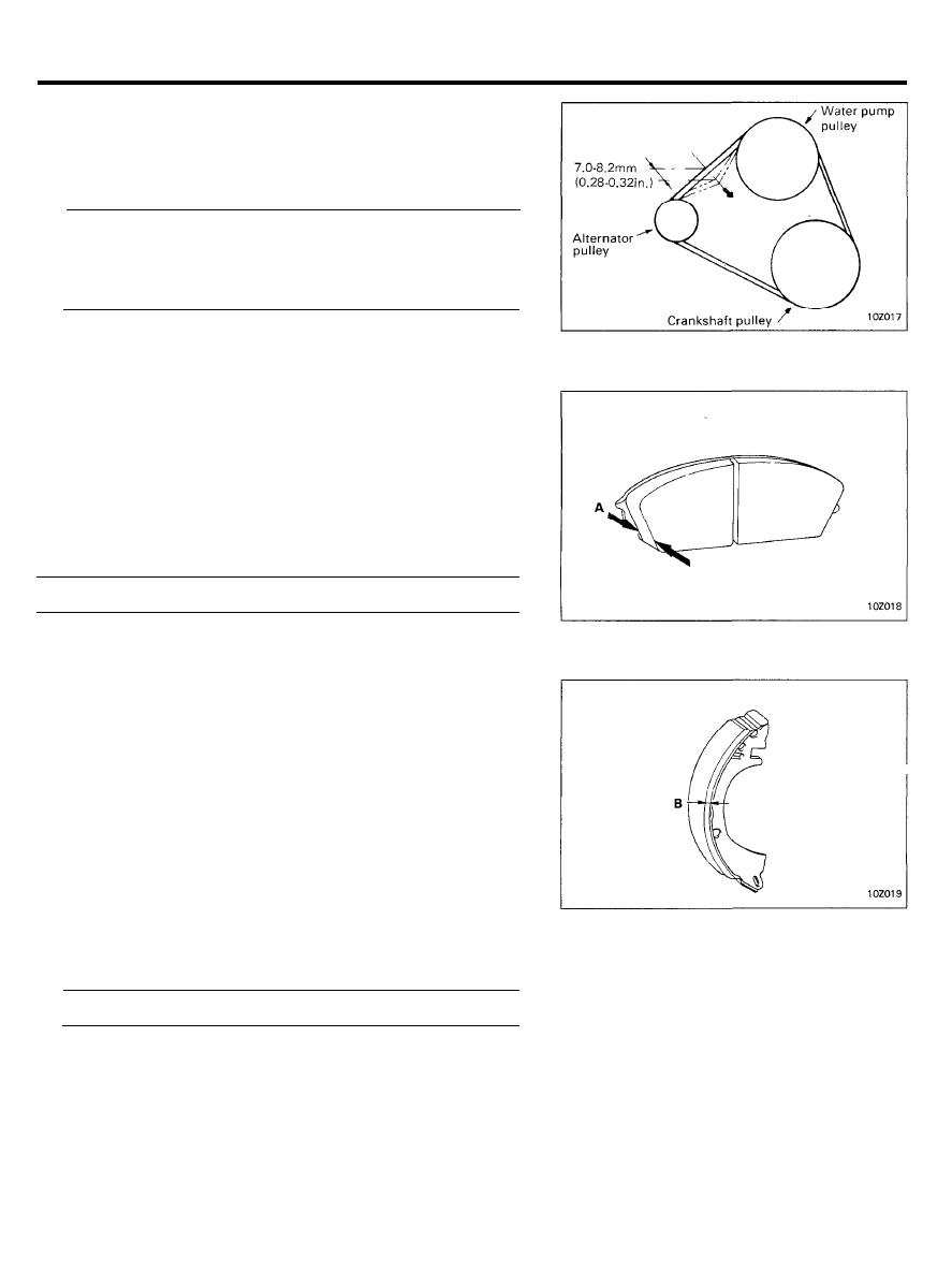
DRIVE BELT
1. To check belt tension, apply moderate pressure (approxi-
mately 100 N, 22 lb) midway between the pulleys.
Check the deflection and adjust if necessary.
Drive belt deflection . . . . . . . . 7.0-8.2 mm (0.28-0.32 in.)
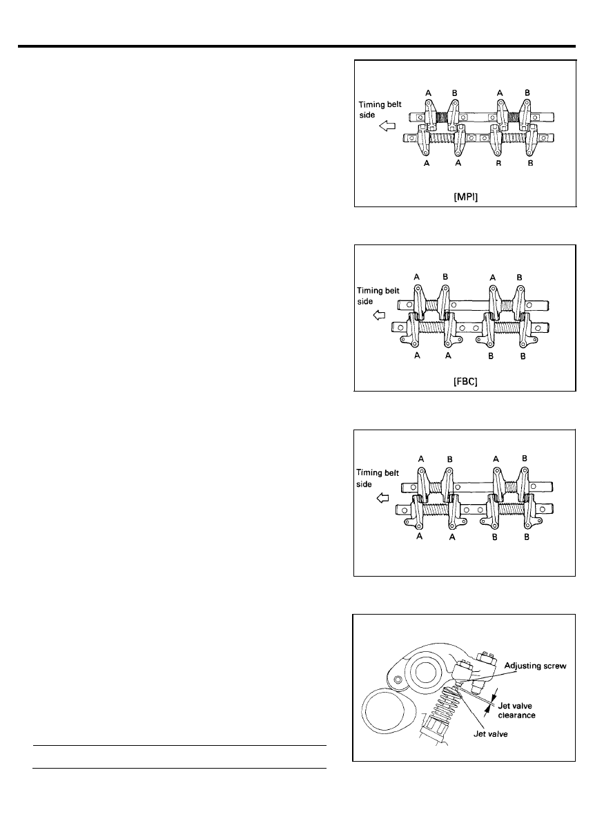
VALVE CLEARANCE
Intake and Exhaust Valves
Adjustment condition
Normal operating temperature [Cooling temperature 80 to 95°C
(176 to 205°F)]
1. Place piston of No. 1 cylinder at top dead center of
compression stroke to adjust valve clearances marked A, as
shown, in the next page.
2.
Loosen nut and adjust to specification with adjusting screw.
Then retighten nut.
Valve clearance (on hot engine)
Intake. . . . . . . . . . . . . . . . . . . . . . . . 0.15 mm (0.006 in.)
Exhaust . . . . . . . . . . . . . . . . . . . 0.25 mm (0.010 in.)
MAINTENANCE SERVICE
3.
After nut has been retightened, recheck to see if clearance
is correct.
4. Place piston in No. 4 cylinder at top dead center on
compression stroke to adjust valve clearance marked B, as
shown.
5. Adjust by repeating steps 2 and 3.
6. Check idle speed and readjust if necessary.
Jet Valve
[FBC]
Adjustment condition:
Normal operating temperature. [Coolant temperature 80 to 95°C
(176 to 205°F)]
NOTE
1) An incorrect jet valve clearance will affect the emission
levels and could also cause engine troubles.
2) Adjust the jet valve clearance before adjusting the intake
valve clearance. The cylinder head bolts should be
retightened before attempting this adjustment.
3) The jet valve clearance should be adjusted with the intake
valve adjusting screw fully loosened.
1. Place piston of No. 1 cylinder at top dead center of
compression stroke to adjust valve clearances marked A of
intake valve side.
2.
Back off the intake valve adjusting screw (two or more turns).
3.
Loosen the lock nut on the jet valve adjusting screw.
4.
Back off the jet valve adjusting screw and place a 0.25 mm
(0.01 in.) leaf of the feeler gauge between the top end of
the jet valve stem and the bottom end of the adjusting screw.
Jet valve clearance (on hot engine) . . 0.25 mm (0.010 in.)
1 0 - 8
MAINTENANCE SERVICE
5. Screw in the adjusting screw (clockwise) until the bottom
end of the adjusting screw touches the feeler gauge. Since
the jet valve spring is weak in tensile strength, use special
care not to force the jet valve in. Be careful particularly if
the adjusting screw is hard to turn.
6. While holding the adjusting screw in place with a
screwdriver, tighten the lock nut firmly.
7. Check with leaf of the feeler gauge to ensure a 0.25 mm
(0.010 in.) clearance.
8. Adjust the intake valve clearance.
9. Place piston in No. 4 cylinder at top dead center on
compression stroke to adjust valve clearances marked B of
intake valve side.
10. Adjust by repeating steps 2 and 8.
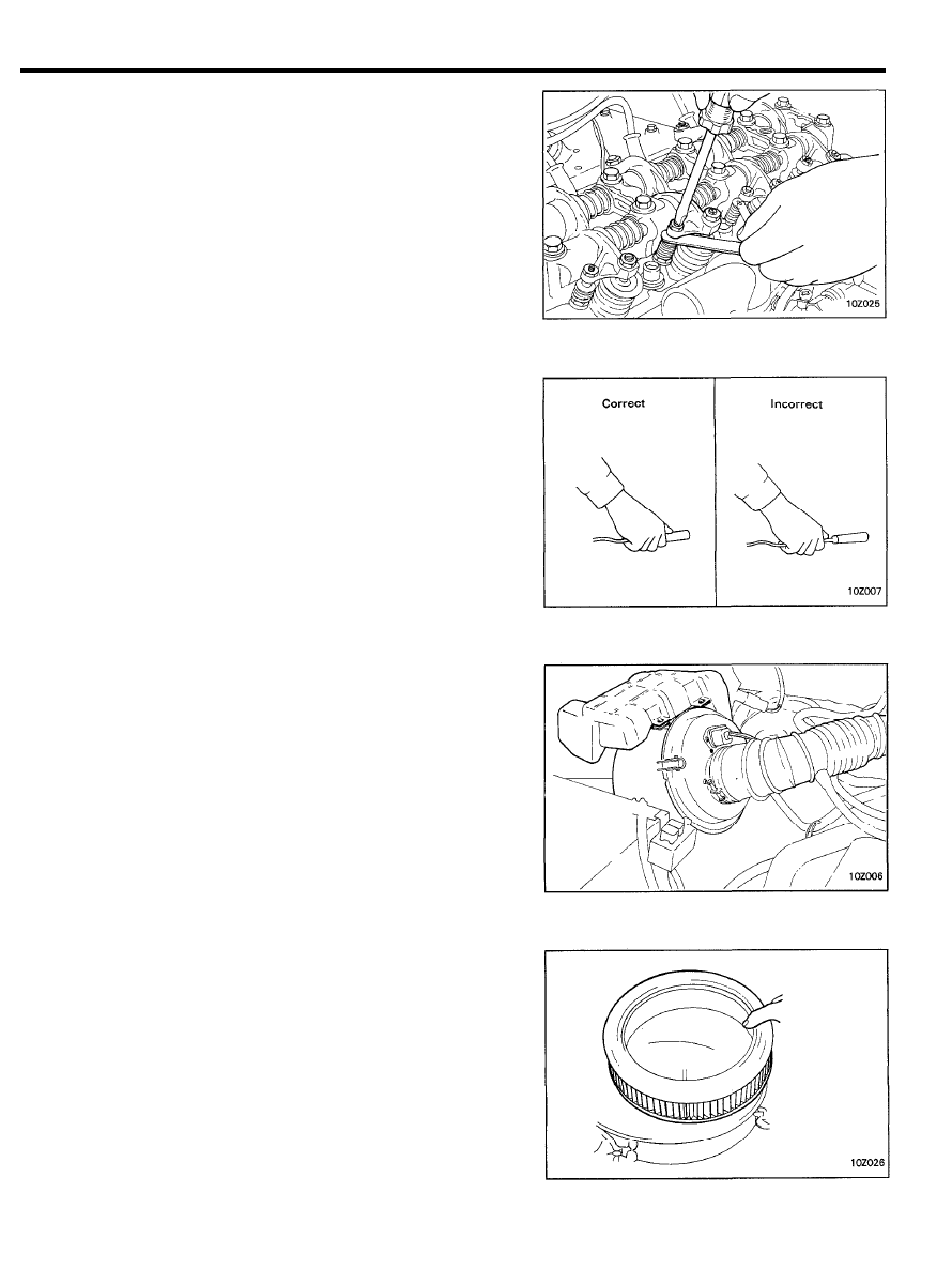
REPLACEMENT OF IGNITION CABLES
The ignition cables should be replaced periodically with new
ones. After replacing, make sure that the ignition cables and
terminals are properly connected and fully seated.
NOTE:
When disconnecting an ignition cable, be sure to hold cable
cap. If the cable is disconnected by pulling on the cable alone
an open circuit might result.
REPLACEMENT OF THE AIR FILTER [MPI]
The air filter will become dirty during use, which will decrease
fuel economy. Replace with a new one.
1. Remove the air intake hose and air duct.
2. Disconnect the connector for the air-flow sensor from the
air filter cover.
3. Disconnect the air filter cover clip.
4. Remove the air filter cover.
NOTE
The air filter cover should be removed carefully because
it includes the air-flow sensor.
5. Remove the air filter element.
6.
Set in a new air filter element and clamp the air filter cover.
AIR CLEANER FILTER [FBC]
1. Remove the wing nut. Use pliers only if the wing nut is
difficult to remove.
2. Unsnap the clips.
3.
Remove the filter by hand, and replace it with a new filter.
1 0 - 9
MAINTENANCE SERVICE
4.
Install the air filter, the cover and housing, taking care that
the arrows are aligned.
5. Tighten the wing nut by hand and attach the clips.
FBC SYSTEM
Ignition Timing (Check and adjust as required)
Adjustment condition:
Lights, electric cooling fan and all accessories are off, and
transaxle is in neutral.
1.
Run the engine at fast idle until the coolant temperature is
raised to 80 to 95°C (176-205°F)
2. Run the engine at the specified curb idle speed.
3. Read the ignition timing. (Refer to the next page).
If not within specifications, adjust the ignition timing by
loosening the distributor fitting nut and rotating the
distributor.
Basic Ignition Timing Set Procedure at High-altitude
Adjustment condition:
Lights, electric cooling fan and all accessories are off, and
transaxle is in neutral.
1.
Run the engine at fast idle until the coolant temperature is
raised to 80-95°C (176-205°F)
2. Disconnect the hoses from the distributor and temporarily
seal the hoses end (Vacuum OFF).
3. Run the engine at the specified idle speed (rpm).
4. Read the ignition timing.
If not within specifications, adjust the ignition timing by
rotating the distributor after loosening the distributor fitting
nut.
5. Reconnect the vacuum hoses to the distributor.
Engine Idle Speed Check Procedure
Check to see if the engine is idling at the specified speed. If not,
adjust the idle speed to the specified value by the adjusting
procedure.
NOTE
The improper setting (throttle valve opening) will increase
exhaust gas temperature at deceleration, reducing catalyst life
greatly and deteriorating exhaust gas cleaning performance.
1 0 - 1 0
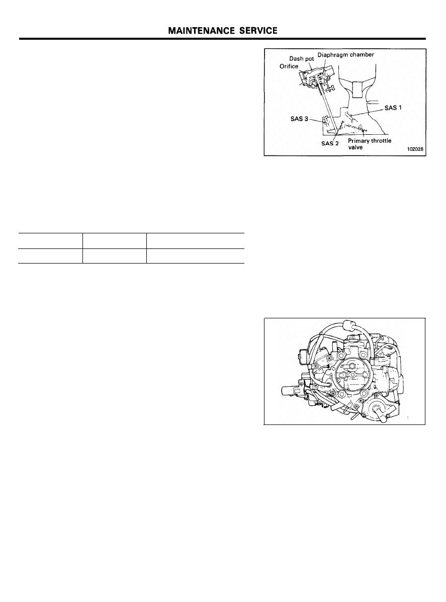
Engine Idle Speed Adjustment
Adjustment condition:
Lights and all accessories are off, transaxle is in neutral and
parking brake pulled.
1. Run the engine at fast idle till the coolant temperature
reaches 80 to 95°C (176-205°F).
2.
Run the engine for more than 5 seconds at an engine speed
of 2,000 to 3,000 rpm.
3. Run the engine at idle for 2 minutes.
4. Using a tachometer, check the idling speed. If it does not
meet specifications, readjust the speed to the normal
specification using the idle speed adjusting screw SAS 1.
Engine Tune-up Specifications
Idle rpm
Idle up rpm
700 ± 50
800 ± 50
Ignition timing
BTDC 5° ± 1
o
Carburetor Choke Mechanism And Linkage
Apply solvent to the choke pinion and shaft to remove dirt, oil
and any other deposits.
Move the choke valve back and forth to distribute the solvent.
Throttle Position System
1.
Check if the plunger of throttle position sensor follows the
movement of the cam mounted on the throttle shaft with
good response. Also check the sensor body and plunger for
damage and cracks.
2. Using a screwdriver, check the throttle sensor mounting
screws for looseness.
3. Check if the throttle sensor has specified output. Refer to
FUEL SYSTEM GROUP.
NOTE
The throttle sensor output is used for feedback control.
Therefore, if the setting is disturbed in use, the driveability
and exhaust gas will be adversely affected.
1 0 - 1 1
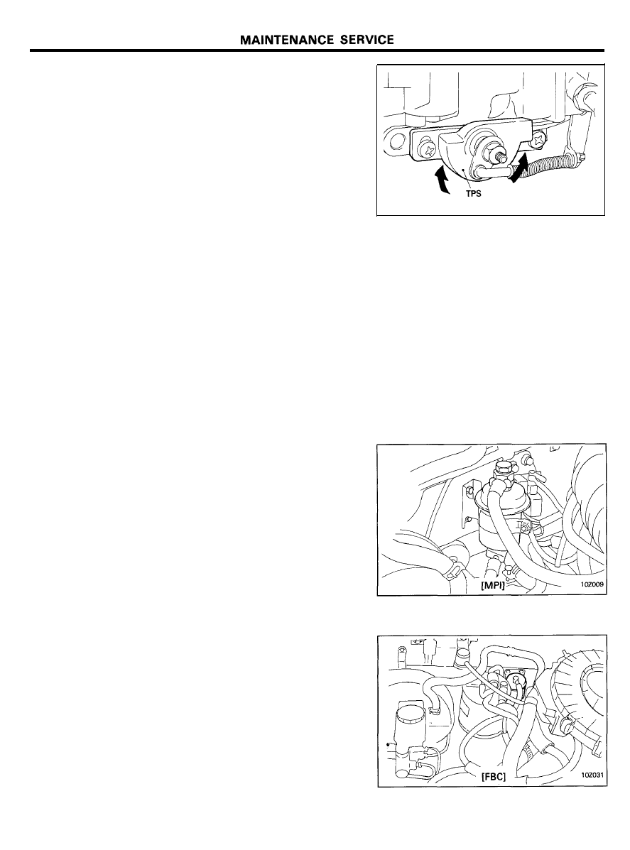
Throttle Position Sensor
1. With the engine stopped; remove the air cleaner from the
engine and perform the following check.
1) Check the linkage of throttle position sensor for
operation.
To do this, operate the throttle lever manually for
acceleration and deceleration and check if the linkage
rotates the movement of the cam (mounted on the
throttle shaft) with good response.
2) Check the throttle sensor body for damage and cracks.
3)
Using a screwdriver or the like, check the throttle sensor
mounting screws for looseness.
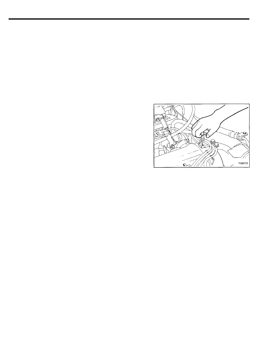
FUEL SYSTEM
Tank, Lines And Connections
1. Check for damage or leakage in the fuel lines and
connections.
2. Inspect the surface of fuel hoses for heat and mechanical
damage. Hard and brittle rubber, cracking, checking, tears,
cuts, abrasions and excessive swelling indicate deterioration
of the rubber.
3. If the fabric casing of the rubber hose is cracked or worn,
the hoses should be changed.
Fuel Filter
1 0 - 1 2
MAINTENANCE SERVICE
CRANKCASE EMISSION CONTROL
SYSTEM (PCV valve)
The crankcase ventilation system must be kept clean to maintain
good engine performance.
Periodic servicing is required to remove combustion products
from the PCV valve.
1.
Disconnect the ventilation hose from the positive crankcase
ventilation (PCV) valve. Then, remove PCV valve from the
rocker cover and reconnect it to the ventilation hose.
2.
Idle the engine and put a finger to the open end of PCV valve
to make sure that intake manifold vacuum is felt on the
finger.
NOTE:
At this time, the plunger inside the PCV valve should move
back and forth.
3. If no vacuum is felt, replace the PCV valve and clean the
ventilation hose in cleaning solvent or replace if necessary.
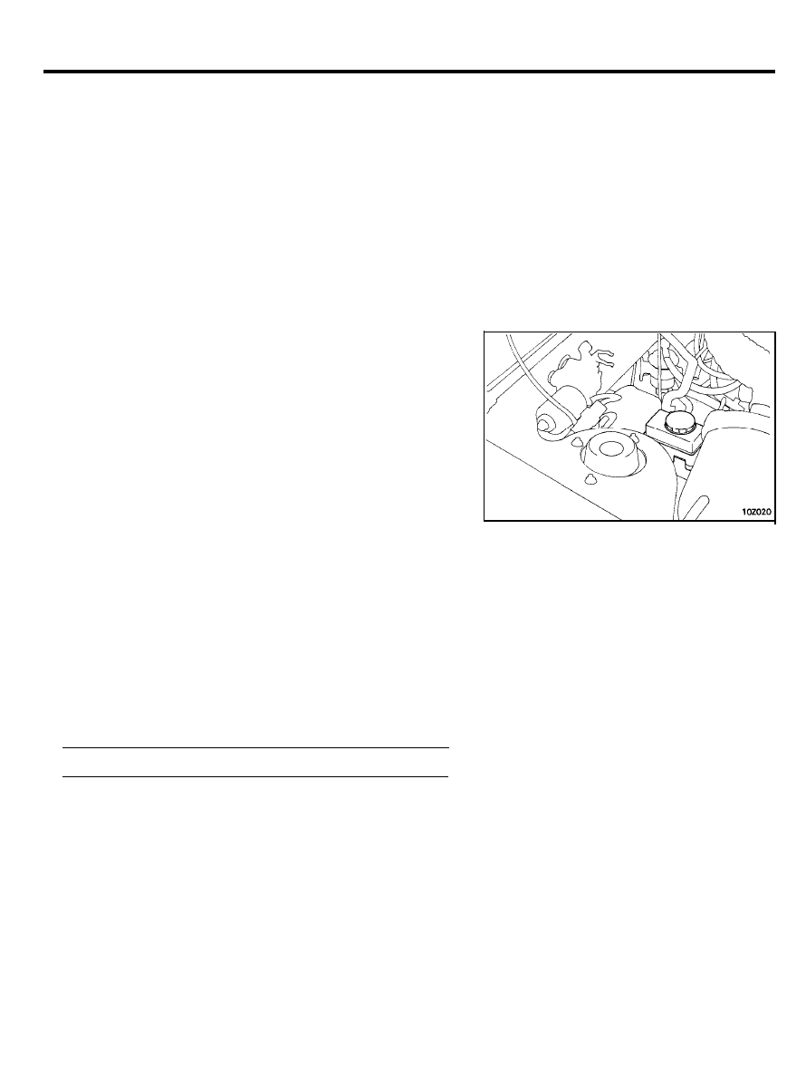
EVAPORATIVE EMISSION CONTROL
SYSTEM
1.
If the fuel-vapor vent line is clogged or damaged, a fuel-vapor
mixture escapes into the atmosphere causing excessive
emission. Disconnect the line at both ends, and blow it clean
with compressed air. Remove the filler cap from the filler
pipe and check to see that the filler cap is seating properly
on the fuel filler pipe.
2. The overfill limiter (2-way valve) installed on the vapor line
between the fuel check valve and fuel tank outlet should be
checked for correct operation.
CANISTER (Replace)
If or when the canister filter becomes clogged, the purge air
volume will decrease and consequently, the canister capacity will
be reduced.
1 0 - 1 3
REPLACEMENT OF OXYGEN SENSOR
The oxygen sensor is a device which controls the fuel mixture.
If the oxygen sensor is damaged, the exhaust emission as well
as driveability deteriorates. Therefore, it should be replaced
when recommended or when a failure occurs.
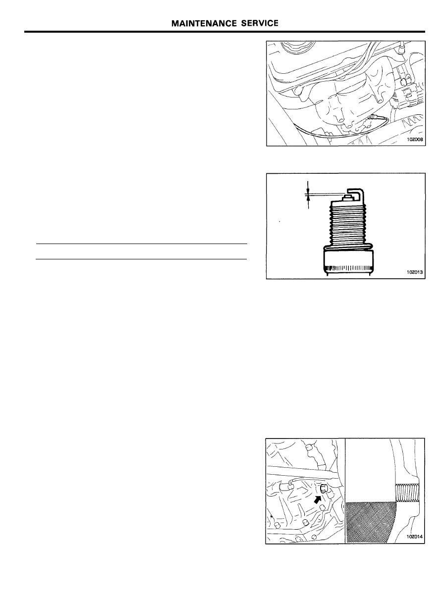
SPARK PLUGS
1. Spark plugs must fire properly to assure proper engine
performance and emission-control. They should operate
satisfactorily in normal vehicle service for the specified
maintenance interval or they should be replaced.
2. The new plugs should be checked for the proper gap.
Plug gap . . . . . . . . . . . . . . . . . 1.0-1.1 mm (0.039-0.043 in.)
TIMING BELT
For disassembly and assembly procedures, refer to “ENGINE
GROUP”.
TRANSAXLE OIL LEVEL INSPECTION
Inspect each component for evidence of leakage, and check the
oil level by removing the filler plug. If the oil is contaminated,
it is necessary to replace it with new oil.
1. With the vehicle parked at a level place, remove the filler
plug and make sure that there is oil 5-9 mm (0.2-0.4 in.)
downward from the threaded lower surface.
2.
Check to be sure that the transaxle oil is not noticeably dirty,
and that it has a suitable viscosity.
1 0 - 1 4
MAINTENANCE SERVICE
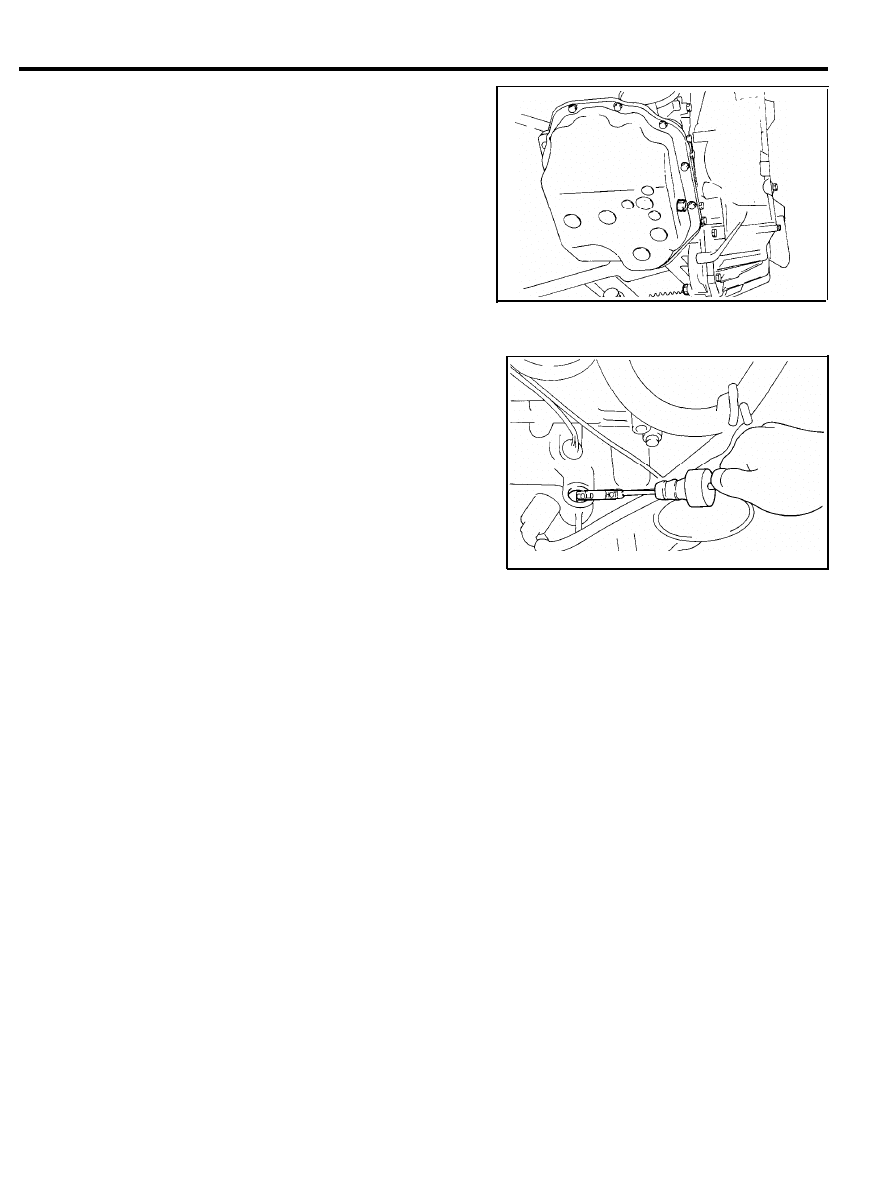
AUTOMATIC TRANSAXLE (Change fluid)
Drain the fluid and check whether there is any evidence of
contamination.
Replenish with new fluid after the cause of any contamination
has been corrected.
1.
2.
3.
4.
5.
6.
7.
8.
9.
Remove drain plug to let fluid drain.
Remove the oil pan.
Check the oil filter for clogging and damage and replace if
necessary.
Clean both gasket surfaces of transaxle case and oil pan.
Install oil pan with new gasket and tighten oil pan bolts to
10-12 Nm (100-120 kg.cm, 7.2-8.7 lb.ft).
Tighten drain plug with gasket to 30-35 Nm (300-350
kg.cm, 22-25 lb.ft).
Supply 4 liters (8.5 pints) of the recommended ATF (Refer
to the page 10-6.) into case through dipstick hole. [Total
quantity of ATF required is 6.1 liters (12.9 pints). Actually
however, approx. 4.5 liters (9.5 pints) of fluid can be replaced
because rest of fluid remains in torque converter.]
Start engine and allow to idle for at least two minutes.
Then, with parking brake on, move selector lever momen-
tarily to each position, ending in “N” Neutral position.
Add sufficient ATF to bring fluid level to lower mark. Recheck
fluid level after transaxle is at normal operating temperature.
Fluid level should be between upper and lower marks of
“HOT” range. Insert dipstick fully to prevent dirt from
entering transaxle.
COOLING SYSTEM
Check the cooling system for damaged hoses, loose or seeping
connections, or other possible causes of coolant loss.
Antifreeze
The engine cooling system is provided with a mixture of 50%
ethylene glycol anti-freeze and 50% water at the time of
manufacture.
Since the cylinder head and water pump body are made of
aluminum alloy casting, be sure to use 30 to 60% ethylene glycol
antifreeze coolant to provide corrosion protection and freezing
prevention.
NOTE
If the concentration of the antifreeze is below 30%. the
anti-corrosion property will be adversely affected. In addition,
if the concentration is above 60%. both the antifreezing and
engine cooling properties will decrease, adversely affecting
the engine. For these reasons, be sure to maintain the
concentration level within the specified range.
1 0 - 1 5
MAINTENANCE SERVICE
Measurement of Antifreeze Concentration
Run the engine until coolant is fully mixed. Drain some coolant
(antifreeze), measure temperature and specific gravity of the
coolant. Determine concentration and safe working temperature.
If the coolant is short of antifreeze, add antifreeze up to a
concentration of 50%.
Coolant Change
WARNING
Hot engine coolant can injure you.
Never open the radiator cap when the engine is hot.
Allow it to cool first.
When removing the radiator cap, use care to avoid
contact with hot coolant or steam. Place shop towel over
the cap and turn the cap counterclockwise a little to let
pressure escape through the vinyl tube. After relieving
the pressure, remove the cap by slowly turning it
counterclockwise.
1.
2.
3.
4.
5.
6.
7.
Remove the radiator cap, radiator drain plug and engine
drain plug to drain coolant.
Remove the reserve tank and drain coolant.
After draining coolant completely, reinstall the drain plugs
and flush the engine and radiator using a radiator cleaning
fluid.
After the flushing is completed, completely drain the
cleaning fluid and install the radiator and engine drain plug.
By referring to the section on coolant is Cooling System
Group, select an appropriate concentration for safe operating
temperature within the range of 30 to 60%. Refill the system
with a high quality ethylene glycol antifreeze at the selected
concentration.
A convenient mixture is 50% water and 50% antifreeze
solution [Freezing point: -36°C (-32.8°F)].
Reinstall the radiator cap.
After running the engine a while, check the coolant level and
add coolant until the specified coolant level is maintained.
Add coolant to the reserve tank between the “FULL” and
“LOW” mark if necessary.
NOTE
Do not overfill the reserve tank.
1 0 - 1 6
MAINTENANCE SERVICE
AIR CONDITIONER SYSTEM
1. To check belt tension, apply pressure (approximately 100N,
22 lb) midway between the pulleys. Check the deflection and
adjust if necessary.
Belt deflection
Drive belt . . . . . . . . . . . . . . . . . . 7.0-8.2 mm (0.28-0.32 in.)
Air conditioner compressor belt . . . . . . . . . . . . . . . . . . . . . . . . .
8.0-10.0 mm (0.32-0.40 in.)
FRONT DISC BRAKE PADS
Check for fluid contamination and wear. Replace complete set
of pads if defective.
WARNING
The pads for the right and left wheels should be replaced at
the same time. Never “split” or intermix brake pad sets. All
pads must be replaced as a complete set.
Thickness of lining “A” [Limit]. . . . . . . . . . . . 1.0 mm (0.04 in.)
REAR DRUM BRAKE LININGS AND REAR
WHEEL CYLINDERS
1. Remove the brake drum and check the thickness of brake
shoe lining for wear. Check the automatic brake adjusting
system by hand to see if it operates smoothly. Also see if
the gears are in proper mesh with each other. To assure
smooth functioning, apply a very thin coat of grease to the
friction surface of adjuster and link shaft.
2.
Inspect the wheel cylinder boots for evidence of a brake fluid
leak. Visually check the boots for cuts, tears or heat cracks.
(A slight amount of fluid on the boot may not be a leak, but
may be preservative fluid used at assembly.)
1) Checking the Brake Shoes for wear.
Thickness of lining “B” [Limit] . . . . . . . . . 1.0 mm (0.04 in.)
1 0 - 1 7
MAINTENANCE SERVICE
BRAKE HOSES
Inspection of brake hoses and tubing should be included in all
brake service operations.
The hoses should be checked for :
1. Correct length, severe surface cracking, pulling, scuffing or
worn spots. (If the fabric casing of the hoses is exposed by
cracks or abrasion in the rubber hose cover, the hoses should
be replaced. Eventual deterioration of hose may occur with
possible bursting failure.).
2. Faulty installation, casing twisting or interference with
wheel, tire or chassis.
BRAKE FLUID (Inspect fluid level and check
for leaks)
1. Check to make certain that the brake fluid is between the
MAX and A line markings on the fluid reservoir. Fill as
required.
2. With disc brakes, the fluid level can be expected to fall as
the brake pads wear. A rapid fluid loss indicates a leak in
the brake system which should be inspected and repaired
immediately.
CAUTION:
Take care in handling brake fluid as it is harmful to the
eyes and may cause damage to painted surfaces and
should be cleaned immediately.
Change Fluid
1. Check the brake system for leakage before replacing brake
fluid.
Completely drain the brake fluid with the bleeder screws
loosened on each brake and refill the brake system with new
brake fluid.
Recommended fluid . . . . . Brake Fluid conforming to DOT 3
2. The reservoir cap must be fully tightened to avoid
contamination from foreign matter or moisture.
WARNING:
DO NOT ALLOW PETROLEUM BASE FLUID TO CON-
TAMINATE THE BRAKE FLUID
1 0 - 1 8
MAINTENANCE SERVICE
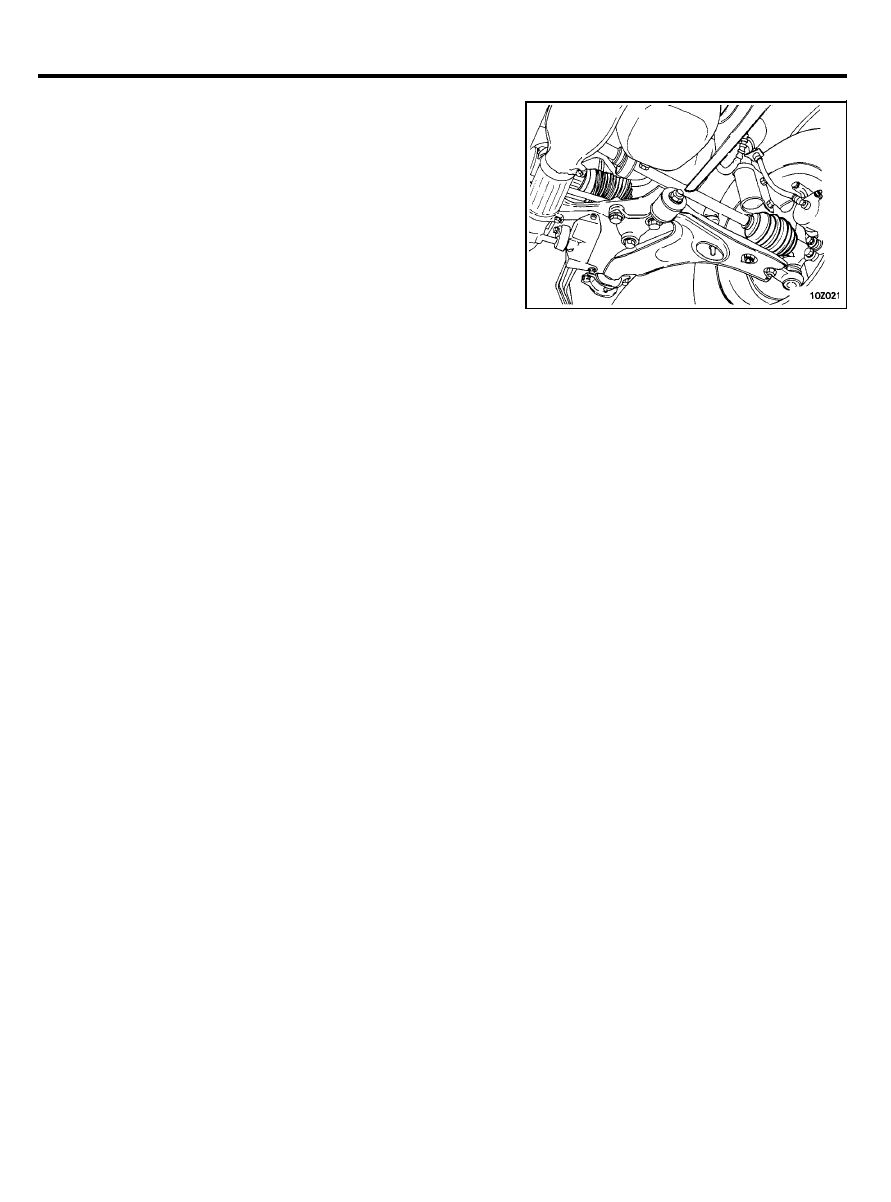
BALL JOINT AND STEERING LINKAGE
SEALS STEERING AND DRIVE SHAFT BOOTS
1.
2.
These components, which are permanently lubricated at the
factory, do not require periodic lubrication. Damaged seals
and boots should be replaced to prevent leakage or
contamination of the grease.
Inspect the dust cover and boots for proper sealing leakage
and damage. Replace them if defective.
POWER STEERING OIL PUMP BELT
(Check and service as required)
1.
Inspect the belt for evidence of cuts and cracks. Replace, if
necessary.
2. Check belt for proper tension. If necessary, adjust the belt
tension as follows.
1) Push the belt with a force of 100 N (22 lb) at a point
halfway between the power steering oil pump pulley and
water pump pulley. The belt deflection should be 7 to 10
mm (0.28-0.39 in.)
2)
If belt deflection is not within specified limits, loosen oil
pump mounting bolt, and move the oil pump to obtain
proper belt deflection at 100 N (22 lb) force.
POWER STEERING FLUID LEVEL
(Inspect fluid level)
1.
Park the vehicle on a flat, level surface, start the engine, and
then turn the steering wheel several times to raise the
temperature of the fluid to approximately 50°C (122°F).
2. With the vehicle still idling, turn the wheel all the way to
the left and right several times.
Check the fluid in the oil reservoir for foaming, check the
fluid level, and replenish the fluid in the oil reservoir through
the oil filter if necessary.
POWER STEERING HOSES
(Check for deterioration or leaks)
1. Check the hose connections for fluid leaks.
2. The power steering hoses should be replaced if there are
severe surface cracking, pulling, scuffing or worn spots.
Deterioration of the hoses could cause premature failure.
1 0 - 1 9

MAINTENANCE SERVICE
REAR WHEEL BEARINGS
(Inspect for grease leaks)
Inspect for evidence of grease leakage round the hub cap and
the back of the hub. If there is leakage of grease. remove the
hub and inspect its oil seal for damage. Clean the grease off the
hub and bearing and repack with specified new grease.
EXHAUST SYSTEM
1.
Check for holes and gas leaks due to damage, corrosion, etc.
2. Check the joints and connections for looseness and gas
leaks.
3. Check the hanger rubber and brackets for damage.
1 0 - 2 0
Wyszukiwarka
Podobne podstrony:
96ZJ 0 LUBRICATION AND MAINTENANCE
93ZJ Secc 0 Lubrication and Maintenance
4 Steyr Operation and Maintenance Manual 8th edition Feb 08
Optibelt Instalation and maintenance
03 Errors and Bugs
Halley RF Troubleshooting and Maintenance Guide V1 0
Popular Mechanics Suspension Repair And Maintenance
Inspection and maintenance (2)
5 Operation and maintenance manual Alamarin jet Ver 1
Production and Maintenance
4 Steyr Operation and Maintenance Manual 8th edition Feb 08
H Beam Piper Fuzzy Papers 03 Fuzzies and Other People
Edgar Rice Burroughs New Tarzan 03 Tarzan and the Snake People # Barton Werper
SpyARPA BAA 13 03 Safe and Secure Ops Amend 3
Jayne Ann Krentz Arcane Society 03 Sizzle and Burn
Scott, Martin Thraxas 03 Thraxas and the Sorcerers
więcej podobnych podstron