©
exida
IEC 61508 Overview Report, Version 2.0, January 2, 2006
Page 1 of 29
IEC 61508 Overview Report
A Summary of the
IEC 61508 Standard for Functional Safety of
Electrical/Electronic/Programmable Electronic Safety-Related
Systems
exida
Sellersville, PA 18960, USA
+1-215-453-1720

©
exida
IEC 61508 Overview Report, Version 2.0, January 2, 2006
Page 2 of 29
1 Overall Document Summary
IEC 61508 is an international standard for the “functional safety” of electrical, electronic, and
programmable electronic equipment. This standard started in the mid 1980s when the
International Electrotechnical Committee Advisory Committee of Safety (IEC ACOS) set up a
task force to consider standardization issues raised by the use of programmable electronic
systems (PES). At that time, many regulatory bodies forbade the use of any software-based
equipment in safety critical applications. Work began within IEC SC65A/Working Group 10 on a
standard for PES used in safety-related systems. This group merged with Working Group 9
where a standard on software safety was in progress. The combined group treated safety as a
system issue.
The total IEC 61508 standard is divided into seven parts.
Part 1: General requirements (required for compliance);
Part 2: Requirements for electrical/electronic/programmable electronic safety-related systems
(required for compliance);
Part 3: Software requirements (required for compliance);
Part 4: Definitions and abbreviations (supporting information)
Part 5: Examples of methods for the determination of safety integrity levels (supporting
information)
Part 6: Guidelines on the application of parts 2 and 3 (supporting information)
Part 7: Overview of techniques and measures (supporting information).
Parts 1, 3, 4, and 5 were approved in 1998. Parts 2, 6, and 7 were approved in February 2000.
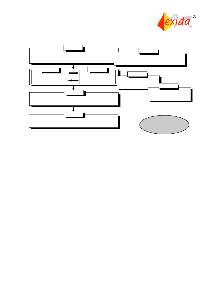
The relationship between the technical requirements presented in parts 1, 2, and 3 and the
supporting information in parts 4 through 7 is shown in Figure 1.
©
exida
IEC 61508 Overview Report, Version 2.0, January 2, 2006
Page 3 of 29
Figure 1: Technical requirements of IEC 61508.
Although the standard was initially criticized for its “extensive” documentation requirements and
use of unproven “statistical” techniques for hardware failures, in many industries it represents a
great step forward. The standard focuses attention on risk-based safety-related system design,
which should result in far more cost-effective implementation. The standard also requires the
attention to detail that is vital to any safe system design. Because of these features and the
large degree of international acceptance for a single set of documents, many consider the
standard to be major advance for the technical world.
OBJECTIVES OF THE STANDARD
IEC 61508 is a basic safety publication of the International Electrotechnical Commission (IEC).
As such, it is an “umbrella” document covering multiple industries and applications. A primary
objective of the standard is to help individual industries develop supplemental standards,
tailored specifically to those industries based on the original 61508 standard. A secondary goal
of the standard is to enable the development of E/E/PE safety-related systems where specific
application sector standards do not already exist.
Several such industry specific standards have now been developed with more on the way. IEC
61511 has been written for the process industries. IEC 62061 has been written to address
machinery safety. IEC 61513 has been written for the nuclear industry. All of these standards
build directly on IEC 61508 and reference it accordingly.
SCOPE
The 61508 standard covers safety-related systems when one or more of such systems
incorporates mechanical/electrical/electronic/programmable electronic devices. These devices
can include anything from ball valves, solenoid valves, electrical relays and switches through to
complex Programmable Logic Controllers (PLCs). The standard specifically covers possible
hazards created when failures of the safety functions performed by E/E/PE safety-related
PART 1
PART 1
Operation and
maintenance
,
modification
and
retrofit
,
decommissioning or disposal
of
E/E/PE
safety
-
related
systems
PART 1
Installation and
commissioning
and
safety validation
of
E/E/PE
safety
-
related
systems
PART 2
PART 3
Realisation
phase for
safety
-
related
software
Realisation
phase for
E/E/PE
safety
-
related
systems
Risk based approaches
to
the development
of
the safety integrity requirements
PART 5
Guidelines for the
application
of
part
2 and 3
PART 6
Technical
requirements
Development
of
the overall safety requirements
(
scope
,
hazard
and
risk analysis
)
Overview
of
techniques
and
measures
PART 7
PART 1
PART 1
Operation and
maintenance
,
modification
and
retrofit
,
decommissioning or disposal
of
E/E/PE
safety
-
related
systems
PART 1
Installation and
commissioning
and
safety validation
of
E/E/PE
safety
-
related
systems
PART 2
PART 3
Realisation
phase for
safety
-
related
software
Realisation
phase for
E/E/PE
safety
-
related
systems
Risk based approaches
to
the development
of
the safety integrity requirements
PART 5
Guidelines for the
application
of
part
2 and 3
PART 6
Technical
requirements
Development
of
the overall safety requirements
(
scope
,
hazard
and
risk analysis
)
Overview
of
techniques
and
measures
PART 7
©
exida
IEC 61508 Overview Report, Version 2.0, January 2, 2006
Page 4 of 29
systems occur. The overall program to insure that the safety-related E/E/PE system brings
about a safe state when called upon to do so is defined as “functional safety.”
IEC 61508 does not cover safety issues like electric shock, hazardous falls, long-term exposure
to a toxic substance, etc.; these issues are covered by other standards. IEC 61508 also does
not cover low safety E/E/PE systems where a single E/E/PE system is capable of providing the
necessary risk reduction and the required safety integrity of the E/E/PE system is less than
safety integrity level 1, i.e., the E/E/PE system is only available 90 percent of the time or less.
IEC 61508 is concerned with the E/E/PE safety-related systems whose failure could affect the
safety of persons and/or the environment. However, it is recognized that the methods of IEC
61508 also may be applied to business loss and asset protection cases.
FUNDAMENTAL CONCEPTS
The standard is based on two fundamental concepts: the safety life cycle and safety integrity
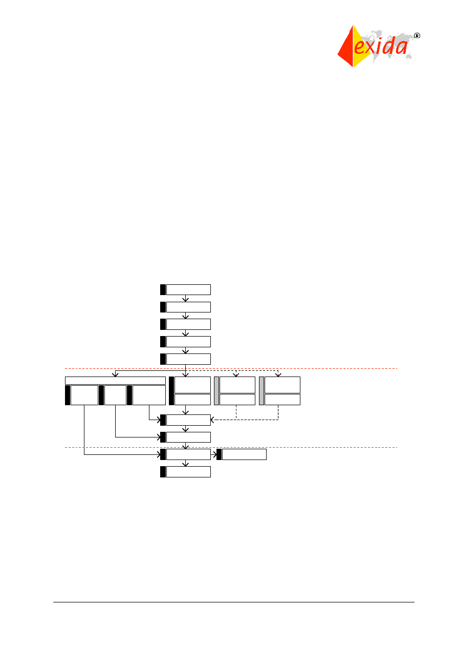
levels. The safety life cycle is defined as an engineering process that includes all of the steps
necessary to achieve required functional safety. The safety life cycle from IEC 61508 is shown
in Figure 2.
Figure 2: Safety life cycle from IEC 61508.
It should be noted that the safety life cycle as drawn in the ISA84.01 standard (Figure 3) looks
different from that in IEC 61508. However, they convey the same intent and both should be
viewed as similarly acceptable processes.
The basic philosophy behind the safety life cycle is to develop and document a safety plan,
execute that plan, document its execution (to show that the plan has been met) and continue to
follow that safety plan through to decommissioning with further appropriate documentation
throughout the life of the system. Changes along the way must similarly follow the pattern of
planning, execution, validation, and documentation.
!ANALYSIS"
(End User / Consultant)
!REALISATION"
(Vendor / Contractor /
End User)
Concept
Overall Scope
Definition
Hazard & Risk
Analysis
Overall Safety
Requirements
Safety Requirements
Allocation
Safety-related
systems :
E/E/PES
Realisation
Overall Installation
& Commissioning
Overall Safety
Validation
Overall Operation &
Maintenance
Decommissioning
Safety-related
systems : other
Technology
Realisation
External Risk
Reduction
Facilities
Realisation
Overall Planning
Installation &
Commissioning
Planning
Validation
Planning
Operation &
Maintenance
Planning
11
10
9
5
4
3
2
1
12
13
14
16
Overall Modification
& Retrofit
15
8
7
6
!OPERATION"
(End User / Contractor)
©
exida
IEC 61508 Overview Report, Version 2.0, January 2, 2006
Page 5 of 29
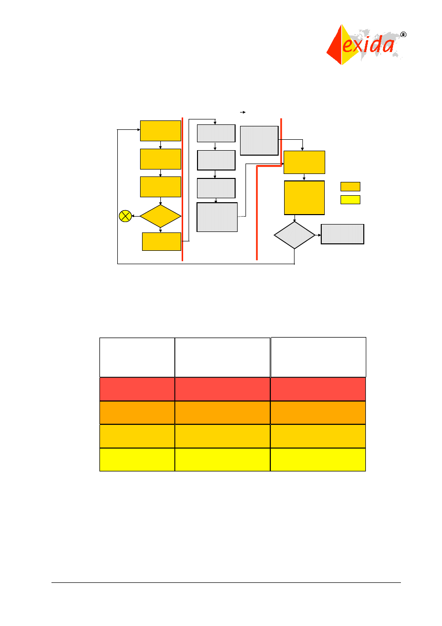
Figure 3: Safety life cycle from ISA84.01.
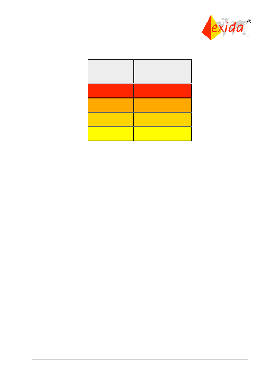
Safety integrity levels (SILs) are order of magnitude levels of risk reduction. There are four SILs
defined in IEC 61508. SIL1 has the lowest level of risk reduction. SIL4 has the highest level of
risk reduction. The SIL table for “demand mode” is shown in Figure 4. The SIL table for the
continuous mode is shown in Figure 5.
Figure 4: Safety integrity levels – demand mode.
Conceptual
Process Design
Hazard Analysis/
Risk Assessment
Develop non-
SIS Layers
Develop Safety
Specification
SIS Conceptual
Design
SIS Detailed
Design
SIS Installation,
Commissioning
and Pre-startup
Acceptance Test
SIS
Required?
No
Yes
Establish
Operating and
Maintenance
Procedures
Pre-startup
Safety Review
(Assessment)
Define Target
SIL
SIS startup,
operation,
maintenance,
Periodic
Functional Tests
Modify,
Decommission
?
Modify
Decommission
SIS
Decommissioning
Not Covered
by S84.01
ANALYSIS
REALISATION
OPERATION
Covered by
S84.01
Safety Integrity
Level
SIL 4
SIL 3
SIL 2
SIL 1
Probability of failure
on demand, average
(Low Demand mode of
operation)
Risk Reduction
Factor
>=10
-5
to <10
-4
>=10
-4
to <10
-3
>=10
-3
to <10
-2
>=10
-2
to <10
-1
100000 to 10000
10000 to 1000
1000 to 100
100 to 10
©
exida
IEC 61508 Overview Report, Version 2.0, January 2, 2006
Page 6 of 29
Figure 5: Safety integrity levels – continuous mode
The mode differences are:
Low demand mode – where the frequency of demands for operation made on a safety-related
system is no greater than twice the proof test frequency;
High demand or continuous mode – where the frequency of demands for operation made on a
safety-related system is greater than twice the proof check frequency.
Note that the proof test frequency refers to how often the safety system is completely tested and
insured to be fully operational.
NOTE: The definitions in Part 4 of the IEC 61508 standard include an arbitrary one year time
interval to distinguish between low demand and high/continuous demand. This is arbitrary and
has no relevance to probability calculation.
While the continuous mode appears to be far more stringent than the demand mode, it should
be remembered that the units for the continuous mode are per hour. The demand mode units
assume a time interval of roughly one year per the definition. Considering the fact that there are
about 10,000 hours in a year (actual 8,760), the modes are approximately the same in terms of
safety metrics.
Basically speaking, functional safety is achieved by properly designing a Safety Instrumented
System (SIS) to carry out a Safety Instrumented Function (SIF) at a reliability indicated by the
Safety Integrity Level (SIL). The concepts of risk and safety integrity are further discussed in
Part 5 of the standard.
COMPLIANCE
The IEC 61508 standard states: “To conform to this standard it shall be demonstrated that the
requirements have been satisfied to the required criteria specified (for example safety integrity
level) and therefore, for each clause or sub-clause, all the objectives have been met.”
In practice, demonstration of compliance often involves listing all of the IEC 61508 requirements
with an explanation of how each requirement has been met. This applies to both products
developed to meet IEC 61508 and specific application projects wishing to claim compliance.
Safety Integrity
Level
SIL 4
SIL 3
SIL 2
SIL 1
Probability of
dangerous failure
per hour
(Continuous mode of operation)
>=10
-9
to <10
-8
>=10
-8
to <10
-7
>=10
-7
to <10
-6
>=10
-6
to <10
-5

©
exida
IEC 61508 Overview Report, Version 2.0, January 2, 2006
Page 7 of 29
Because IEC 61508 is technically only a standard and not a law, compliance is not always
legally required. However, in many instances, compliance is identified as best practice and thus
can be cited in liability cases. Also, many countries have incorporated IEC 61508 or large parts
of the standard directly into their safety codes, so in those instances it indeed has the force of
law. Finally, many industry and government contracts for safety equipment, systems, and
services specifically require compliance with IEC 61508. So although IEC 61508 originated as a
standard, its wide acceptance has led to legally required compliance in many cases.
PARTS OF THE STANDARD
Part 1 covers the basic requirements of the standard and provides a detailed presentation of the
safety life cycle. This section is considered to be the most important, as it provides overall
requirements for documentation, compliance, management of functional safety, and functional
safety assessment. Three annexes provide examples of documentation structure (Annex A), a
personnel competency evaluation (Annex B), and a bibliography (Annex C).
Part 2 covers the hardware requirements for safety-related systems. Many consider this part,
along with part 3, to be the key area for those developing products for the safety market. Part 2
is written with respect to the entire system but many of the requirements are directly applicable
to safety-related hardware product development. Part 2 covers a detailed safety life cycle for
hardware as well as specific aspects of assessing functional safety for the hardware. Part 2 also
has detailed requirements for techniques to deal with “control of failures during operation” in
Annex A (required for compliance). This annex covers hardware fault tolerance, diagnostic
capability requirements and limitations, and systematic safety integrity issues for hardware.
Annex B of Part 2 (required for compliance) contains listings of “techniques and measures” for
“avoidance of systematic failures during different phases of the life cycle.” This covers design,
analysis, and review procedures required by the standard. Annex C of Part 2 (required for
compliance) discusses the calculation of diagnostic coverage factor (what fraction of failures are
identified by the hardware) and safe failure fraction (what fraction of failures lead to a safe
rather than a hazardous state). (Note: see exida technical papers for more detailed information
on these topics.)
Part 3 covers the software requirements for IEC 61508. It applies to any software used in a
safety-related system or software used to develop a safety-related system. This software is
specifically referred to as safety-related software. This part provides details of the software
safety life cycle, a process to be used when developing software. Annex A (required for
compliance) provides a listing of “techniques and measures” used for software development
where different development techniques are chosen depending on the SIL level of the software.
Annex B (required for compliance) has nine detailed tables of design and coding standards and
analysis and testing techniques that are to be used in the safety-related software development,
depending on SIL level of the software and in some cases the choice of the development team.
Part 4 contains the definitions and abbreviations used throughout all parts of the standard. This
section is extremely useful both to those new to the standard and to those already familiar with
it as a reference to the precise meanings of terms in the standard.
Part 5 includes informative Annexes A through E which contain discussion and example
methods for risk, safety integrity, tolerable risk, and SIL selection. It presents several techniques
of SIL selection including both quantitative and qualitative methods. The quantitative method in
Annex C is based on calculating the frequency of the hazardous event from failure rate data or

©
exida
IEC 61508 Overview Report, Version 2.0, January 2, 2006
Page 8 of 29
appropriate predictive methods combined with an assessment of the magnitude of the
consequence compared to the level of risk that can be tolerated in the given situation. The
qualitative risk graph and severity matrixes essentially address the same frequency and
magnitude components, only with general categories rather than numbers before comparing the
situation with the tolerable risk level.
Part 6 provides guidelines on the application of Parts 2 and 3 via informative Annexes A through
E. Annex A gives a brief overview of Parts 2 and 3 as well as example flowcharts of detailed
procedures to help with implementation. Annex B provides example techniques for calculating
probabilities of failure for the safety-related system with tables of calculation results. Equations
that approximate various example architectures are presented, although reliability block
diagrams are used and these can be confusing in multiple failure mode situations. Annex C
shows detailed calculation of diagnostic coverage factor based on FMEDA techniques. (Note:
more information on the FMEDA technique (Failure Modes, Effects, and Diagnostics Analysis) is
available in exida.com courses and papers.) Annex D shows a method for estimating the effect
of common cause modes of failure (beta factors) in a redundant hardware architecture. This
method lists relevant parameters and provides a method of calculation. Annex E shows
examples applying the software integrity level tables of Part 3 for two different safety software
cases.
Part 7 contains important information for those doing product development work on equipment
to be certified per IEC 61508. Annex A addresses control of random hardware failures. It
contains a reasonable level of detail on various methods and techniques useful for preventing or
maintaining safety in the presence of component failures. Annex B covers the avoidance of
systematic failures through the different phases of the safety life cycle. Annex C provides a
reasonably detailed overview of techniques for achieving high software safety integrity. Annex D
covers a probabilities-based approach for SIL determination of already proven software.

©
exida
IEC 61508 Overview Report, Version 2.0, January 2, 2006
Page 9 of 29
2 Part 1: General Requirements
SCOPE
The IEC 61508 standard covers safety-related systems when one or more of such systems
incorporate electrical/electronic/programmable electronic devices. This includes mechanical
devices used in such systems, relay-based systems, inherently safe solid-state logic based
systems, and, perhaps most importantly, programmable systems based on microcomputer
technology. The standard specifically covers possible hazards created when failures of the
safety functions performed by E/E/PE safety-related systems occur: This is known as “functional
safety.” Functional safety is the overall program to insure that a safety-related E/E/PE system
brings about a safe state when it is called upon to do so and is different from other safety
issues. For example, IEC 61508 does not cover safety issues like electric shock, long-term
exposure to toxic substances, etc. These safety issues are covered by other standards.
IEC 61508 also does not cover low safety E/E/PE systems where a single E/E/PE system is
capable of providing the necessary risk reduction and the required safety integrity of the E/E/PE
system is less than safety integrity level 1, i.e., the E/E/PE system is only reliable 90 percent of
the time or less. IEC 61508 is concerned with the E/E/PE safety-related systems whose failure
could affect the safety of persons and/or the environment. However, it is recognized that the
methods of IEC 61508 may apply to business loss and asset protection as well. Human beings
may be considered part of a safety-related system, although specific human factor requirements
are not considered in detail in the standard. The standard also specifically avoids the concept of
“fail safe” because of the high level of complexity involved with the E/E/PE systems considered.
CONFORMANCE
Part 1 of the standard contains the general conformance requirements. It states, “To conform to
this standard it shall be demonstrated that the requirements have been satisfied to the required
criteria specified (for example: safety integrity level) and therefore, for each clause or sub-
clause, all the objectives have been met.” There is a statement that acknowledges that the
“degree of rigor” (which determines if a requirement has been met) depends on a number of
factors, including the nature of the potential hazard, degree of risk, etc.
Often, demonstrating compliance involves listing all IEC 61508 requirements with an
explanation of how the requirement has been met. This applies to products developed to meet
IEC 61508 and specific application projects wishing to claim compliance. The high level of
documentation for compliance is consistent with the importance of keeping detailed records
stressed throughout the standard. (Note: exida.com has a suite of products, including a full IEC
61508 requirements database, and documentation templates that can used to form a system of
compliance meeting IEC 61508.)
The language of conformance in the standard is quite precise. If an item is listed as “shall be...”
or “must…“, it is required for compliance. If an item is listed as “may be…” it is not specifically
required for compliance but clear reasoning must be shown to justify its omission.
DOCUMENTATION (Clause 5)
The documentation used in safety-related systems must specify the necessary information such
that safety life cycle activities can be performed. The documentation must also provide enough

©
exida
IEC 61508 Overview Report, Version 2.0, January 2, 2006
Page 10 of 29
information so that the management of functional safety verification and assessment activities
can effectively be accomplished. The overall reasoning is to provide proper support for the plan,
do, and verify theme present throughout the safety life cycle.
This translates into specific requirements for the documentation.
It must:
1. have sufficient information to effectively perform each phase of the safety life cycle as well as
the associated verification activities;
2. have sufficient information to properly manage functional safety and support functional safety
assessment;
3. be accurate and precise;
4. be easy to understand;
5. suit the purpose for which it was intended;
6. be accessible and maintainable;
7. have titles or names indicating the scope of the contents;
8. have a good table of contents and index;
9. have a good version control system sufficient to identify different versions of each document
and indicate revisions, amendments, reviews, and approvals.
MANAGEMENT OF FUNCTIONAL SAFETY (Clause 6)
Managing functional safety includes taking on various activities and responsibilities to insure
that the functional safety objectives are achieved and maintained. These activities must be
documented, typically in a document called the functional safety management (FSM) plan. The
FSM plan should consider:
1. the overall strategy and methods for achieving functional safety, including evaluation
methods and the way in which the process is communicated within the organization;
2. the identification of the people, departments, and organizations that are responsible for
carrying out and reviewing the applicable overall, E/E/PES, or software safety life cycle phases
(including, where relevant, licensing authorities or safety regulatory bodies);
3. the safety life cycle phases to be used;
4. the documentation structure;
5. the measures and techniques used to meet requirements;
6. the functional safety assessment activities to be performed and the safety life cycle phases
where they will be performed;
7. the procedures for follow-up and resolution of recommendations arising from hazard and risk
analysis, functional safety assessment, verification and validation activities, etc.;
8. the procedures for ensuring that personnel are competent;
9. the procedures for ensuring that hazardous incidents (or near misses) are analyzed, and that
actions are taken to avoid repetition;
10. the procedures for analyzing operations and maintenance performance, including periodic
functional safety inspections and audits; the inspection frequency and level of independence of
personnel to perform the inspection/audit should be documented;
11. the procedures for management of change.
All those responsible for managing functional safety activities must be informed and aware of
their responsibilities. Suppliers providing products or services in support of any safety life cycle

©
exida
IEC 61508 Overview Report, Version 2.0, January 2, 2006
Page 11 of 29
phase, shall deliver products or services as specified by those responsible for that phase.
These suppliers also shall have an appropriate quality management system.
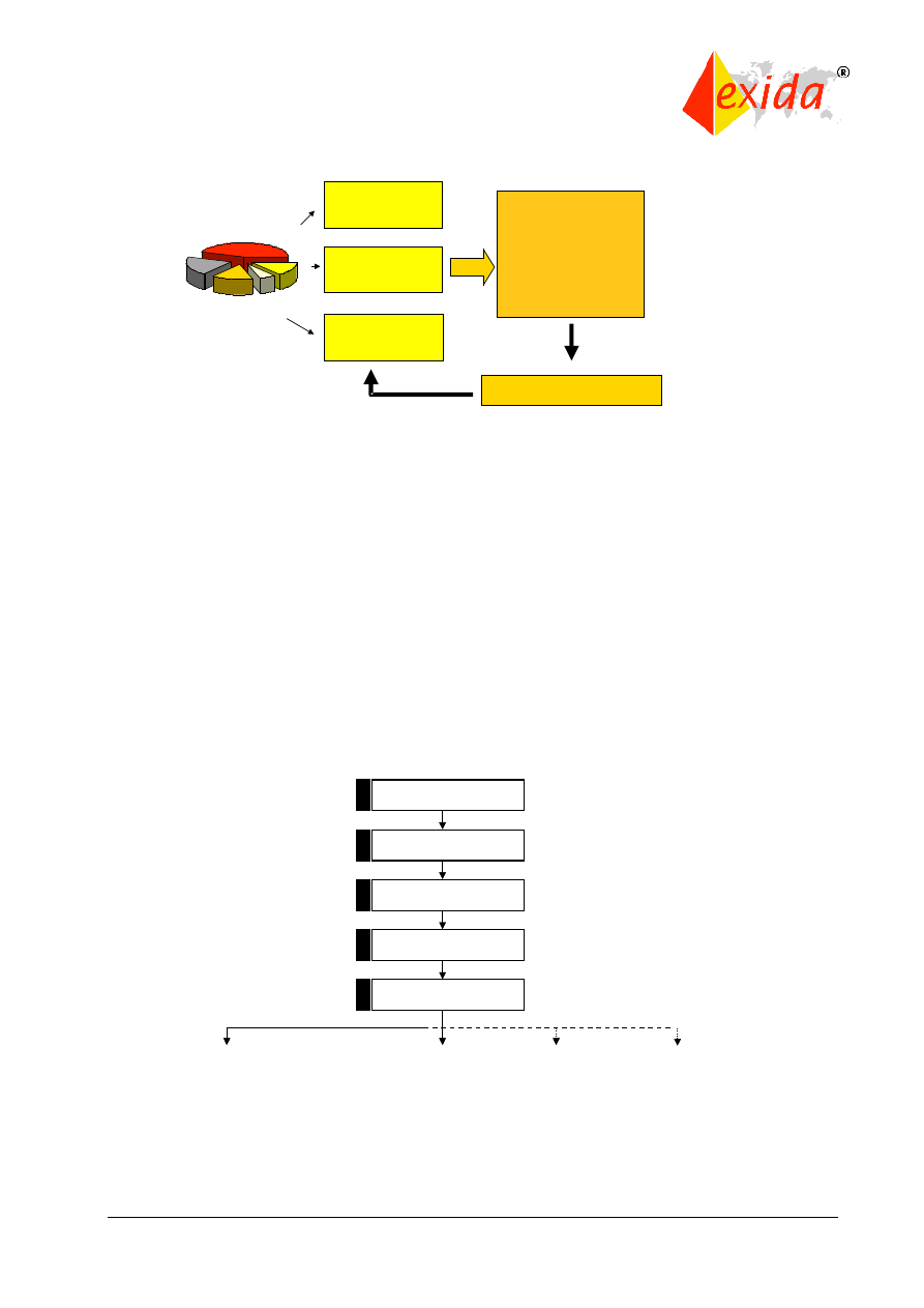
SAFETY LIFE CYCLE REQUIREMENTS (Clause 7)
The safety life cycle can be viewed as a logical “identify-assess-design-verify” closed loop
(Figure 6). The intended result is the optimum design where the risk reduction provided by the
safety-related system matches the risk reduction needed by the process.
Figure 6: Closed loop view of the safety life cycle.
The safety life cycle concept came from studies done by the Health Safety Executive (HSE) in
the United Kingdom. The HSE studied accidents involving industrial control systems and
classified accident causes as shown in Figure 7.
Figure 7: Results of system failure cause study: HSE “Out of Control.”
The basic aspects of the safety life cycle (shown in Figure 8) were created to address all of the
causes identified in the HSE study.
Identify
Analyze
Design
Verify
Specification 44%
Design &
Implementation
15%
Installation & Commissioning
6%
Operation &
Maintenance
15%
Changes after
Commissioning
21%
©
exida
IEC 61508 Overview Report, Version 2.0, January 2, 2006
Page 12 of 29
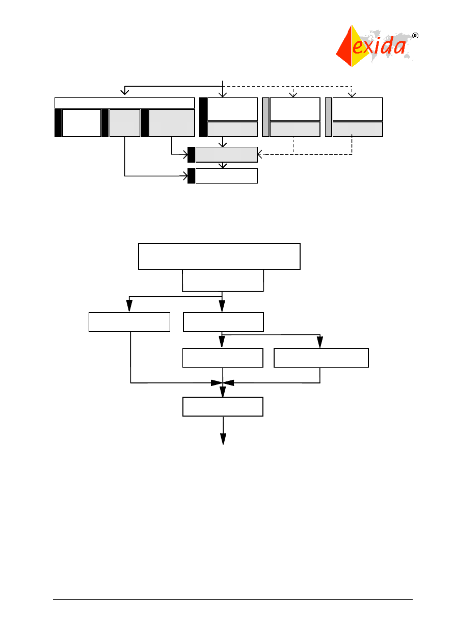
Figure 8: Origin of the safety life cycle.
The first part of the safety life cycle, known as the analysis portion, covers:
-Concept and scope of the system or equipment under control (EUC);
-Hazard and Risk Analysis to identify both hazards and the events that can lead to them,
including
Preliminary Hazards and Operability (HAZOP) study,
Layers of Protection Analysis (LOPA),
Criticality Analysis;
-Creation of overall safety requirements and identification of specific safety functions to prevent
the identified hazards;
-Safety requirements allocation, i.e., assigning the safety function to an E/E/PE safety-related
system, an external risk reduction facility, or a safety-related system of different technology.
This also includes assigning a safety integrity level (SIL) or risk reduction factor required for
each safety function.
These first phases are shown in Figure 9.
Figure 9: First portion of the overall safety life cycle.
The safety life cycle continues with the realization activities as shown in Figure 10.
Safety
Management
Technical
Requirements
Competence
of Persons
Accident
Causes
IEC61508
Safety Life
Cycle
Certification
Concept
Overall Scope
Definition
Hazard & Risk
Analysis
Overall Safety
Requirements
Safety Requirements
Allocation
5
4
3
2
1
Concept
Overall Scope
Definition
Hazard & Risk
Analysis
Overall Safety
Requirements
Safety Requirements
Allocation
5
4
3
2
1
©
exida
IEC 61508 Overview Report, Version 2.0, January 2, 2006
Page 13 of 29
Figure 10: Realization activities in the overall safety life cycle.
The safety systems must be designed to meet the target safety integrity levels as defined in the
risk analysis phase. This requires that a probabilistic calculation be done to verify that the
design can meet the SIL (either in demand mode or continuous mode). The system must also
meet detailed hardware and software implementation requirements given in Parts 2 and 3. One
of the most significant is the “safe failure fraction” restriction (see Part 2). There is a more
detailed subsection of the overall life cycle called the E/E/PE life cycle, which details the
activities in box 9 above. This E/E/PE lifecycle is shown in Figure 11. These activities are
detailed in Part 2 of the standard.
Figure 11: E/E/PES safety life cycle (IEC 61508, Part 2).
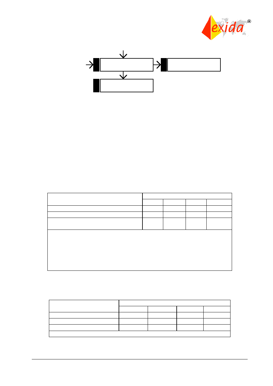
The final operation phases of the overall safety life cycle are shown in Figure 12.
Safety
-
related
systems :
E/E/PES
Realization
Overall Installation
& Commissioning
Overall Safety
Validation
Safety -related
systems : other
Technology
Realization
External Risk
Reduction
Facilities
Realization
Overall Planning
Installation &
Commissioning
Planning
Validation
Planning
Operation &
Maintenance
Planning
11
10
9
12
13
8
7
6
E/E/PES safety
validation
E/E/PES safety requirements
specification
E/E/PES safety
validation planning
E/E/PES design
and development
E/E/PES operation and
maintenance procedures
E/E/PES integration
©
exida
IEC 61508 Overview Report, Version 2.0, January 2, 2006
Page 14 of 29
Figure 12: Operation and Maintenance phases of the overall safety life cycle.
In summary, the safety life cycle generally lays out the different activities required to achieve
functional safety and compliance with the standard. It also should be noted that if all of the “shall
be…” and “must…” conditions are met, other safety life cycle variations also are fully compliant
with the standard.
FUNCTIONAL SAFETY ASSESSMENT (Clause 8)
Part 1 also describes the functional safety assessment activities required by IEC 61508. The
objective of the assessment is to investigate and arrive at a conclusion regarding the level of
safety achieved by the safety-related system. The process requires that one or more competent
persons be appointed to carry out a functional safety assessment. These individuals must be
suitably independent of those responsible for the functional safety being assessed, depending
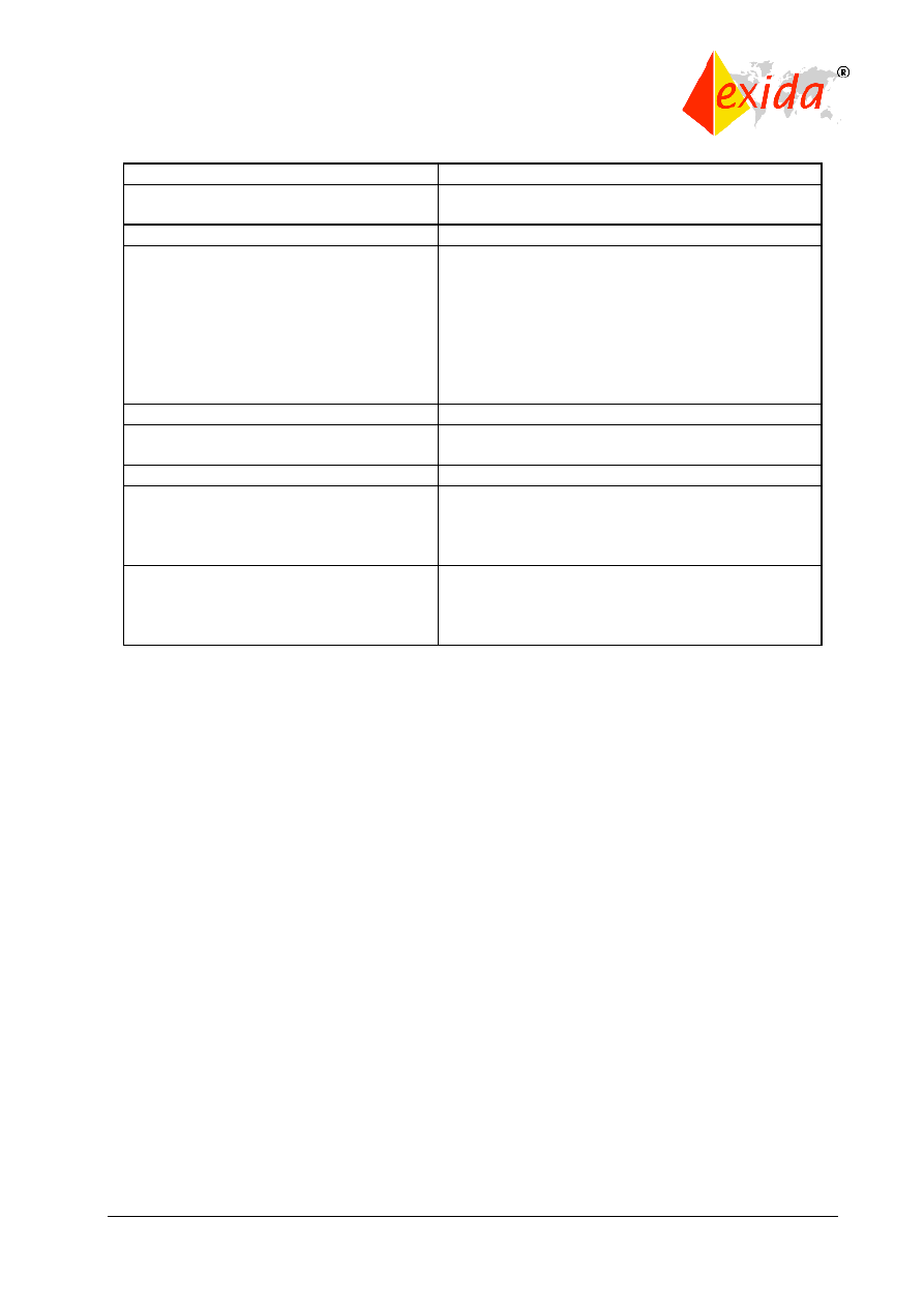
on the SIL and consequences involved. These requirements are shown in Tables 1 and 2.
Table 1: Assessment independence level as a function of consequence.
Table 2: Assessment independence level for E/E/PE and software life cycle activities.
Minimum level of
Consequence
Independence
A
B
C
D
Independent person
HR
HR
1
NR
NR
Independent department
-
HR
2
HR
1
NR
Independent organization
(see note 2 of 8.2.12)
-
-
HR
2
HR
Typical consequences could be:
Consequence A - minor injury (for example temporary loss of function);
Consequence B - serious permanent injury to one or more persons, death
to one person; Consequence C - death to several people;
Consequence D - very many people killed.
Abbreviations – HR - highly recommended, NR – not recommended
Minimum level of
Safety integrity level
Independence
1
2
3
4
Independent person
HR
HR
1
NR
NR
Independent department
-
HR
2
HR
1
NR
Independent organization
-
-
HR
2
HR
Overall Operation &
Maintenance
Decommissioning
14
16
Overall Modification
& Retrofit
15

©
exida
IEC 61508 Overview Report, Version 2.0, January 2, 2006
Page 15 of 29
The functional safety assessment shall include all phases of the safety life cycles. The
assessment must consider the life cycle activities carried out and the outputs obtained. The
assessment may be done in parts after each activity or group of activities. The main
requirement is that the assessment be done before the safety-related system is needed to
protect against a hazard.
The functional safety assessment must consider:
1. All work done since the previous functional safety assessment;
2. The plans for implementing further functional safety assessments;
3. The recommendations of the previous assessments including a check to verify that the
changes have been made.
The functional safety assessment activities shall be consistent and planned. The plan must
specify the personnel who will perform the assessment, their level of independence, and the
competency required. The assessment plan must also state the scope of the assessment,
outputs of the assessment, any safety bodies involved, and the resources required. At the
conclusion of the functional safety assessment, recommendations shall indicate acceptance,
qualified acceptance, or rejection.
Sample Documentation Structure (Annex A)
The documentation has to contain enough information to effectively perform each phase of the
safety life cycle (Clause 7), manage functional safety (Clause 6), and allow functional safety
assessments (Clause 8). However, IEC 61508 does not specify a particular documentation
structure. Users have flexibility in choosing their own documentation structure as long as it
meets the criteria described earlier. . An example set of documents for a safety life cycle project
is shown in Table 3.
©
exida
IEC 61508 Overview Report, Version 2.0, January 2, 2006
Page 16 of 29
Safety Lifecycle phase
Information
Safety requirements
Safety Requirements Specification (safety
functions and safety integrity)
E/E/PES validation planning
Validation Plan
E/E/PES design and development
E/E/PES architecture
Architecture Design Description (hardware
and software);
Specification (integration tests)
Hardware architecture
Hardware Architecture Design Description;
Hardware module design
Detail Design Specification(s)
Component
construction
and/or
procurement
Hardware modules;
Report (hardware modules test)
Programmable electronic integration Integration Report
E/E/PES operation and maintenance
procedures
Operation and Maintenance Instructions
E/E/PES safety validation
Validation Report
E/E/PES modification
E/E/PES modification procedures;
Modification Request;
Modification Report;
Modification Log
Concerning all phases
Safety Plan;
Verification Plan and Report;
Functional Safety Assessment Plan and
Report
Table 3: Documentation examples.
Personnel Competency (Annex B)
IEC 61508 specifically states, “All persons involved in any overall, E/E/PES or software safety
life cycle activity, including management activities, should have the appropriate training,
technical knowledge, experience and qualifications relevant to the specific duties they have to
perform.” It is suggested that a number of things be considered in the evaluation of personnel.
These are:
1. engineering knowledge in the application;
2. engineering knowledge appropriate to the technology;
3. safety engineering knowledge appropriate to the technology;
4. knowledge of the legal and safety regulatory framework;
5. the consequences of safety-related system failure;
6. the assigned safety integrity levels of safety functions in a project;
7. experience and its relevance to the job.
The training, experience, and qualifications of all persons should be documented. The Certified
Functional Safety Expert (CFSE) program was designed to help companies show personnel
competency in several different safety specialties.
Bibliography (Annex C)
A list of many related IEC standards, ISO standards, and other relevant references is provided.
©
exida
IEC 61508 Overview Report, Version 2.0, January 2, 2006
Page 17 of 29
3 Part 2: Hardware Requirements
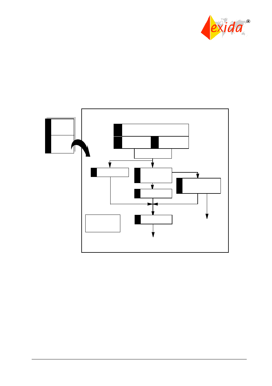
IEC 61508 Part 2 covers specific requirements for safety-related hardware. As in other parts of
the standard, a safety life cycle is to be used as the basis of requirement compliance. (Figure 9
shows the general safety life cycle model.) The hardware safety life cycle is an expanded plan
for Phase 9 of the overall safety life cycle from Part 1 that is focused on the design of the control
hardware for safety systems. As for the overall safety life cycle, there are requirements for a
functional safety management plan and safety requirements specification including all
verification and assessment activities.
9.1.2
Safety integrity
requirements
specification
Safety functions
requirements
specification
Safety-related
systems:
E/E/PES
Realisation
9
Box 9 in figure 2
of part 1
E/E/PES safety
validation
9.6
9.1
9.1.1
E/E/PES safety requirements
specification
To box 12 in figure 2 of part 1
E/E/PES safety
validation planning
E/E/PES design and
development
including software
(see IEC 61508-3)
9.3
9.2
E/E/PES installation,
commissioning,
operation, and
maintenance procedures
9.5
9.4
E/E/PES integration
One E/E/PES safety
lifecycle for each
E/E/PE safety-related
system
To box 14
in figure 2
of part 1
E/E/PES safety lifecycle
NOTE See also IEC 61508-6, A.2(b)
Figure 13: Hardware safety life cycle.
The safety requirements specification (described in Clause 7.2) shall include details on both the
safety function and the safety integrity level of that function. Some of these safety function
details are:
-how safe state is achieved
-response time
-operator interfaces
-operating modes of equipment under control
-required E/E/PES behavior modes -start-up requirements
Some of the safety integrity level details are:
-SIL for each function
-high or low demand class for each function
-environmental extremes
-electromagnetic immunity limits
One particular aspect of the hardware design and development requirements (Clause 7.4) is the
limit on the safety integrity level achievable by any particular level of fault tolerant safety
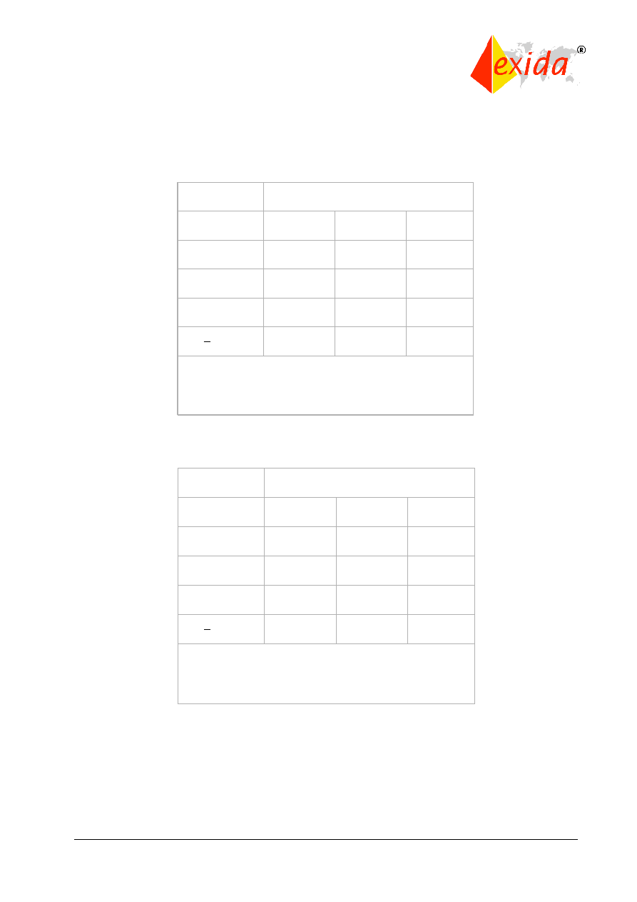
©
exida
IEC 61508 Overview Report, Version 2.0, January 2, 2006
Page 18 of 29
redundancy. These are shown in Tables 4 and 5 for various fractions of failures leading to a
safe state.
Table 4: Type A safe failure fraction chart.
Table 5: Type B safe failure fraction chart.
Type A components are described as simple devices with well-known failure modes and a solid
history of operation. Type B devices are complex components with potentially unknown failure
modes, i.e., microprocessors, ASICs, etc.
Tables 4 and 5 represent limits on the use of single or even dual architectures in higher SIL
levels. This is appropriate based on the level of uncertainty present in the failure data as well as
in the SIL calculations themselves.
Safe failure
fraction
Hardware fault tolerance (see note 1)
0
1
2
< 60 %
SIL1
SIL2
SIL3
60 % - < 90 %
SIL2
SIL3
SIL4
90 % - < 99 %
SIL3
SIL4
SIL4
> 99 %
SIL3
SIL4
SIL4
NOTE 1
A hardware fault tolerance of N means that N+1 faults could cause a loss of
the safety function.
Safe failure
fraction
Hardware fault tolerance (see note 1)
0
1
2
< 60 %
SIL1
SIL2
SIL3
60 % - < 90 %
SIL2
SIL3
SIL4
90 % - < 99 %
SIL3
SIL4
SIL4
> 99 %
SIL3
SIL4
SIL4
NOTE 1
A hardware fault tolerance of N means that N+1 faults could cause a loss of
the safety function.
Safe failure
fraction
Safe failure
fraction
Hardware fault tolerance (see note 1)
Hardware fault tolerance (see note 1)
00
11
22
< 60 %
< 60 %
SIL1
SIL1
SIL2
SIL2
SIL3
SIL3
60 % - < 90 %
60 % - < 90 %
SIL2
SIL2
SIL3
SIL3
SIL4
SIL4
90 % - < 99 %
90 % - < 99 %
SIL3
SIL3
SIL4
SIL4
SIL4
SIL4
> 99 %
> 99 %
SIL3
SIL3
SIL4
SIL4
SIL4
SIL4
NOTE 1
A hardware fault tolerance of N means that N+1 faults could cause a loss of
the safety function.
NOTE 1
A hardware fault tolerance of N means that N+1 faults could cause a loss of
the safety function.
Safe failure
fraction
Hardware fault tolerance (see note 1)
0
1
2
< 60 %
Not
Allowed
SIL1
SIL2
60 % - < 90 %
SIL1
SIL2
SIL3
90 % - < 99 %
SIL2
SIL3
SIL4
> 99 %
SIL3
SIL4
SIL4
NOTE 1
A hardware fault tolerance of N means that N+1 faults could cause a loss of
the safety function.
Safe failure
fraction
Hardware fault tolerance (see note 1)
0
1
2
< 60 %
Not
Allowed
SIL1
SIL2
60 % - < 90 %
SIL1
SIL2
SIL3
90 % - < 99 %
SIL2
SIL3
SIL4
> 99 %
SIL3
SIL4
SIL4
NOTE 1
A hardware fault tolerance of N means that N+1 faults could cause a loss of
the safety function.
Safe failure
fraction
Safe failure
fraction
Hardware fault tolerance (see note 1)
Hardware fault tolerance (see note 1)
00
11
22
< 60 %
< 60 %
Not
Allowed
Not
Allowed
SIL1
SIL1
SIL2
SIL2
60 % - < 90 %
60 % - < 90 %
SIL1
SIL1
SIL2
SIL2
SIL3
SIL3
90 % - < 99 %
90 % - < 99 %
SIL2
SIL2
SIL3
SIL3
SIL4
SIL4
> 99 %
> 99 %
SIL3
SIL3
SIL4
SIL4
SIL4
SIL4
NOTE 1
A hardware fault tolerance of N means that N+1 faults could cause a loss of
the safety function.
NOTE 1
A hardware fault tolerance of N means that N+1 faults could cause a loss of
the safety function.

©
exida
IEC 61508 Overview Report, Version 2.0, January 2, 2006
Page 19 of 29
Note the separate phase specifically devoted to integrating the software and hardware before
validating the safety of the combined system (described in Clause 7.5). Operation and
maintenance procedures and documentation are described in Clause 7.6 while validation,
modification, and verification phase details are provided in the remaining parts of Clause 7.
Control of Failures during Operation (Annex A)
This annex limits claims that can be made for self diagnostic capabilities and also recommends
methods of failure control. Numerous types of failures are addressed including random,
systematic, environmental, and operational failures. It should be noted that following these
methods does not guarantee that a given system will meet a specific SIL.
Avoidance of Systematic Failures during Different Phases of the Life Cycle (Annex B)
Here, numerous tables present recommended techniques for different life cycle phases to
achieve different SILs. Again, simply using these techniques does not guarantee a system will
achieve a specific SIL.
Diagnostic Coverage and Safe Failure Fraction (Annex C)
Here, a basic procedure is described for calculating the fraction of failures that can be self-
diagnosed and the fraction that result in a safe state.
4 Part 3: Software Requirements
IEC 61508 Part 3 covers specific requirements for safety-related software. As in other parts of
the standard, a safety life cycle is to be used as the basis of requirement compliance. (Figure 9
shows the general safety life cycle model.) The software safety life cycle is an expanded plan
for Phase 9 of the overall safety life cycle from Part 1 and is closely linked with the hardware life
cycle. As for the overall safety life cycle, there are requirements for a functional safety
management plan and safety requirements specification, including all verification and
assessment activities.
Here the functional safety is addressed in the context of a software quality management system
(QMS) in Clause 6. A detailed functional safety plan is presented as part of this QMS. As in
other parts of the standard, the same key features of change management, demonstration, and
documentation are present.
SOFTWARE FUNCTIONAL SAFETY PLAN (Clause 6)
A software functional safety plan (either as a part of other documentation or as a separate
document) shall define the strategy for the software procurement, development, integration,
verification, validation, and modification as required for the SIL level of the safety-related
system. The plan must specify a configuration management system.
This software configuration management system must:
1. manage software changes to ensure that the specified requirements for software safety are
satisfied;
2. guarantee that all necessary activities have been carried out to demonstrate that the required
software safety integrity has been achieved;
©
exida
IEC 61508 Overview Report, Version 2.0, January 2, 2006
Page 20 of 29
3. accurately maintain all documentation and source code including the safety analysis and
requirements; software specification and design documents; software source code modules;
test plans and results; commercial off the shelf (COTS) and pre-existing software components
which are to be incorporated into the E/E/PE safety-related system; all tools and development
environments which are used to create or test, or carry out any action on, the software of the
E/E/PE safety-related system;
4. prevent unauthorized modifications;
5. document modification/change requests;
6. analyze the impact of a proposed modification;
7. approve or reject the modification request;
8. establish baseline software and document the (partial) integration testing that justifies the
baseline;
9. formally document the release of safety-related software.
Master copies of the software and all documentation should be maintained throughout the
operational lifetime of the released software.
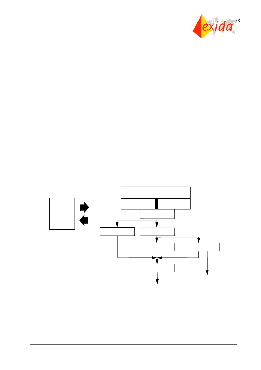
SOFTWARE SAFETY LIFE CYCLE (Clause 7)
IEC 61508 has a considerable but appropriate number of requirements for safety critical
software put forth in the details of the software safety life cycle framework. The major phases of
the software safety life cycle are shown in Figure 14.
Figure 14: Software safety life cycle.
Part 3 requires that a process (such as the safety life cycle) for the development of software
shall be selected and specified during safety planning. Note that the exact process is not
specified, it may be customized according to company preference. Appropriate quality and
safety assurance procedures must be included. Each step of the software safety life cycle must
be divided into elementary activities with the functions, inputs, and outputs specified for each
phase.
Software safety
validation
Safety functions
requirements
specification
Safety integrity
requirements
specification
Software safety requirements
specification
Software safety
validation planning
Software design
and development
Software operation and
modification procedures
PE integration
(hardware/software)
E/E/PES
safety
lifecycle
©
exida
IEC 61508 Overview Report, Version 2.0, January 2, 2006
Page 21 of 29
The standard has complete details of an example software safety life cycle. Many practitioners
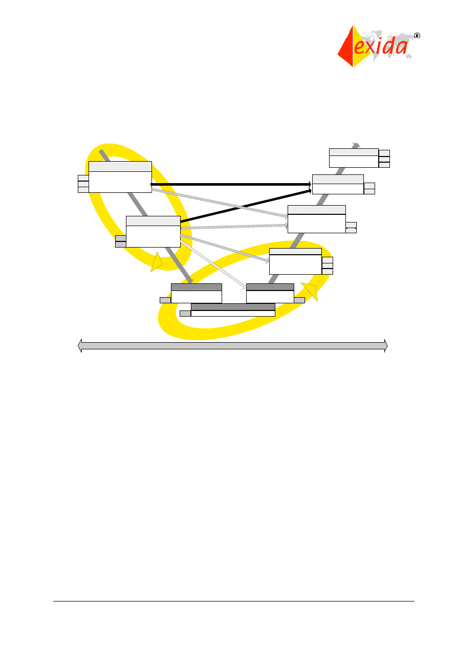
use a version of the V-model. The exida.com iterative V-model is shown in Figure 15.
Figure 15: exida iterative V-model for software development.
During each step of process, appropriate “techniques and measures” must be used.
Part 3 Annexes A and B give recommendations from a list of software techniques.
The standard says, “If at any stage of the software safety life cycle, a change is required
pertaining to an earlier life cycle phase, then that earlier safety life cycle phase and the following
phases shall be repeated”. This natural iterative process is best done in two major loops per
Figure 15.
SOFTWARE SAFETY REQUIREMENTS SPECIFICATION (Clause 7.2)
The functional safety requirements for software must be specified. This can be done in a
separate document or as part of another document. The specification of the requirements for
software safety shall be derived from the specified safety requirements of the safety-related
system and any requirements of safety planning.
The requirements for software safety shall be sufficiently detailed to allow design and
implementation and to allow a functional safety assessment. The software developers should
review the document to verify that it contains sufficient detail. It should be noted that this is often
another iterative process.
The requirements must be clear, precise, verifiable, testable, maintainable, and feasible. The
requirements must also be appropriate for the safety integrity level. and traceable back to the
Detailed Design
Detailed Design
UML
GUI
IEC1131-3 language
Requirements
Requirement Specification
V&V Plan and Procedures
Requirement Specification
V&V Plan and Procedures
Unit / Interface Tests
Unit / Interface Tests
Documentation
Documentation
Guidelines for installation,
operation, maintenance
and error handling
Guidelines for installation,
operation, maintenance
and error handling
Integration Test
Integration Test
Tests to show the correct
interaction of functions
Tests to show the correct
interaction of functions
Graphical Design Spec.
(UML, Pattern)
Interface Spec.
Graphical Design Spec.
(UML, Pattern)
Interface Spec.
Positive
- / Negative
-Tests -
Error ha
ndling
Static + D
ynamic A
nalysis
Additi
onal V
alidat
ion te
sts
(Failu
re sce
narios
)
Use and Mis-Use Szenarios
Validation tests
Functions an
d limitations
.
Additional functions and limitations
Operation and exception handling ins
tructions
Implementation
Implementation
V&V
V&V
D
D
D
Doc
D
Product Maintenance
Product Maintenance
Field Monitoring
Change Management
Field Monitoring
Change Management
Validation
Validation
Automated Regression Tests
Automated Regression Tests
User
V&V
D
V&V
User
User
D
Evolution over Prototypes
Requirements Tracking
Defect Tracking; Configuration Management
D
V&V
D
User
Iteration
Inte
rfac
e S
pec
.
Architecture
1
2
3
4
5
6
7

©
exida
IEC 61508 Overview Report, Version 2.0, January 2, 2006
Page 22 of 29
specification of the safety requirements of the safety-related system. Terminology must be clear
and understandable by those using the document. All modes of operation for the safety-related
system must be listed. The requirements must detail any relevant constraints between the
hardware and the software.
Since the software is often called upon to perform much of the online diagnostics, the
requirements must detail all software self-monitoring, any diagnostic tests performed on the
hardware, periodic testing of critical functions, and means for online testing of safety functions.
If the software also performs non-safety functions, means to insure that the software safety is
not compromised (non-interfering) must also be specified.
SOFTWARE SAFETY VALIDATION PLANNING (Clause 7.3)
A plan must be set up to demonstrate that the software satisfies the safety requirements set out
in the specification. A combination of analysis and testing techniques is allowed and the chosen
techniques must be specified in the plan. The plan must consider:
1. required equipment;
2. when validation will be done;
3. who will do the validation;
4. the modes of operation to be validated including start up, teach, automatic, manual, semi-
automatic, steady state of operation, re-set, shut down, and maintenance;
5. reasonably foreseeable abnormal conditions;
6. identification of the safety-related software that needs to be validated;
7. specific reference to the specified requirements for software safety;
8. expected results and pass/fail criteria.
The plan must show how assessment will be done, who will review the plan, and the assessor’s
level of independence.
SOFTWARE DESIGN AND DEVELOPMENT (Clause 7.4)
Design methods shall be chosen that support abstraction, modularity, information hiding, and
other good software engineering practices. The design method shall allow clear and
unambiguous expression of functionality, data flow, sequencing, and time-dependent data,
timing constraints, concurrency, data structures, design assumptions, and their dependencies.
During design, the overall complexity of the design, its testability, and the ability to make safe
modifications shall be considered. The entire design is considered safety-related even if non-
safety functions are included unless sufficient independence between safety and non-safety can
be demonstrated. If different safety integrity levels are part of the design, the overall design is
only valid for the least stringent SIL of the component parts.
The design must include software functions to execute proof tests and all online diagnostic tests
as specified in the requirements. Software diagnostics shall include monitoring of control flow
and data flow.
The architectural design defines the major components and subsystems of the software. The
architectural design description must include:
1. interconnections of these components;
2 the “techniques and measures” necessary during the software safety life cycle phases to
satisfy requirements for software safety at the required safety integrity level including software
design strategies for fault tolerance and/or fault avoidance (redundancy/diversity);

©
exida
IEC 61508 Overview Report, Version 2.0, January 2, 2006
Page 23 of 29
3. the software safety integrity level of the subsystem/component;
4. all software/hardware interactions and their significance;
5. the design features for maintaining the safety integrity of all data;
6. software architecture integration tests to ensure that the software architecture satisfies the
requirements for software.
It is assumed and permitted that iteration occurs between the design and the requirements
phases. Any resulting changes in requirements must be documented and approved.
Support tools and programming languages must meet the safety integrity needs of the software.
A set of integrated tools, including languages, compilers, configuration management tools, and,
when applicable, automatic testing tools, shall be selected for the required safety integrity level.
Detailed design and coding shall follow the software safety life cycle. Coding standards shall be
employed and must specify good programming practice, prohibit unsafe language features, and
specify procedures for source code documentation including:
1. legal entity;
2. description;
3. inputs and outputs;
4. configuration management history.
The software code must be :
1. readable, understandable, and testable;
2. able to satisfy the specified requirements;
3. reviewed;
4. tested as specified during software design.
INTEGRATION AND TESTING (Clause 7.5)
Tests of the integration between the hardware and software are created during the design and
development phases and specify the following:
1. test cases and test data in manageable integration sets;
2. test environment, tools, and configuration;
3. test criteria;
4. procedures for corrective action on failure of test.
The integration testing results shall state each test and the pass/fail results.
SOFTWARE SAFETY VALIDATION (Clause 7.7)
Software validation is done as an overall check to insure that the software design meets the
software safety requirements and must include the appropriate documentation. The validation
may be done as part of overall system validation or it may be done separately for the software.
Testing must be the primary method of validation with analysis used only to supplement. All
tools used in the validation must be calibrated and an approved quality system must be in place.
If validation is done separately for the software, the validation must follow the software safety
validation plan. For each safety function, the validation effort shall document:
1. a record of the validation activities;
2. the version of the software safety validation plan;

©
exida
IEC 61508 Overview Report, Version 2.0, January 2, 2006
Page 24 of 29
3. the safety function being validated with reference to planned test;
4. test environment (tools and equipment);
5. the results of the validation activity with discrepancies, if any.
If discrepancies occur, a change request must be created and an analysis must be done to
determine if the validation may continue.
OPERATION AND MODIFICATION (Clauses 7.6 and 7.8)
Software modification requires authorization under the procedures specified during safety
planning and must insure that the required safety integrity level is maintained. This authorization
must address:
1. the hazards that may be affected;
2. the proposed change;
3. the reasons for change.
The modification process starts with an analysis on the impact of the proposed software
modification on functional safety. The analysis will determine how much of the safety life cycle
must be repeated.
SOFTWARE VERIFICATION (Clause 7.9)
The software verification process tests and evaluates the results of the software safety life cycle
phases to insure they are correct and consistent with the input information to those phases.
Verification of the steps used in the software safety life cycle must be performed according to
the plan and must be done concurrently with design and development. The verification plan
must indicate the activities performed and the items to be verified (documents, reviews, etc.). A
verification report must include an explanation of all activities and results. Verification must be
performed on:
1. software safety requirements;
2. software architecture design;
3. software system design;
4. software module design;
5. software source code;
6. data;
7. software module testing;
8. software integration testing;
9. hardware integration testing;
10. software safety requirements testing (software validation).
SOFTWARE FUNCTIONAL SAFETY ASSESSMENT (Clause 9)
The software assessment process is similar to the other assessment processes in the standard.
Techniques and measures relevant to this assessment are listed in Annexes A and B as well as
in Part 1 of the standard.

©
exida
IEC 61508 Overview Report, Version 2.0, January 2, 2006
Page 25 of 29
GUIDE TO THE SELECTION OF TECHNIQUES AND MEASURES (Annex A)
Annex A provides ten tables of different techniques relevant to the software safety
requirements, software design and development, architecture design, support tools and
programming languages, detailed design, software module testing, integration testing, safety
validation, modification and functional safety assessment. Different techniques are
“recommended” or “highly recommended” as a function of safety integrity level required. Some
techniques are used alone or in combination with other techniques to show compliance with the
standard.
DETAILED TABLES (Annex B
Annex B provides nine tables of detailed techniques for design and coding standards, dynamic
analysis and testing, functional and black box testing, failure analysis, modeling, performance
testing, semi-formal methods, static analysis, and modular approaches. These tables are also
referenced in the tables from Annex A.
5 Part 4: Abbreviations and Definitions
Part 4 of the standard contains the abbreviations and definitions used throughout the entire
document. Some selected key definitions are:
diversity - different means of performing a required function
equipment under control (EUC) - equipment, machinery, apparatus, or plant used for
manufacturing, process, transportation, medical, or other activities
functional safety - part of the overall safety relating to the EUC and the EUC control system
which depends on the correct functioning of the E/E/PE safety-related systems, other
technology safety-related systems, and external risk reduction facilities
harm - physical injury or damage to the health of people either directly or indirectly as a result of
damage to property or to the environment
hazard - potential source of harm
limited variability language - software programming language, either textual or graphical, for
commercial and industrial programmable electronic controllers with a range of capabilities
limited to their application
redundancy - means, in addition to the means which would be sufficient, for a functional unit to
perform a required function or for data to represent information
risk - combination of the probability of occurrence of harm and the severity of that harm
safety - freedom from unacceptable risk
safety function - function to be implemented by an E/E/PE safety-related system, other
technology safety-related system, or external risk reduction facilities which is intended to
achieve or maintain a safe state for the EUC, with respect to a specific hazardous event
safety integrity - probability of a safety-related system satisfactorily performing the required
safety functions under all the stated conditions within a stated period of time
safety integrity level (SIL) - discrete level (one out of a possible four) for specifying the safety
integrity requirements of the safety functions to be allocated to the E/E/PE safety-related
systems, where safety integrity level 4 has the highest level of safety integrity and safety
integrity level 1 has the lowest
safety life cycle - necessary activities involved in the implementation of safety-related systems,
occurring during a period of time that starts at the concept phase of a project and finishes when

©
exida
IEC 61508 Overview Report, Version 2.0, January 2, 2006
Page 26 of 29
all of the E/E/PE safety-related systems, other technology safety-related systems, and external
risk reduction facilities are no longer available for use
safety-related system - designated system that both:
-implements the required safety functions necessary to achieve or maintain a safe state
for the EUC; and
-is intended to achieve, on its own or with other E/E/PE safety-related systems, other
technology safety-related systems or external risk reduction facilities, the necessary
safety integrity for the required safety functions
systematic failure - failure related in a deterministic way to a certain cause, which can only be
eliminated by a modification of the design or of the manufacturing process, operational
procedures, documentation, or other relevant factors
tolerable risk - risk which is accepted in a given context based on the current values of society
6 Part 5: Examples of Methods for the Determination of Safety
Integrity Levels (Informative)
Part 5 is primarily composed of Annexes A through E which describe key concepts as well as
various methods of SIL selection and verification.
RISK AND SAFETY INTEGRITY – GENERAL CONCEPTS (Annex A)
This annex describes the required safety actions to bridge the gap between the current level of
risk present in the system and the level that can be tolerated in the given situation. This
necessary risk reduction is noted to include contributions from E/E/PE safety-related systems,
other safety-related systems, and external risk reduction methods. Elements of safety integrity
relating to both the hardware and the overall systematic safety integrity are sometimes difficult
to assess. This is part of the basis for SIL only referring to the order of magnitude of risk
reduction for a safety-related system.
ALARP AND TOLERABLE RISK CONCEPTS (Annex B)
Annex B describes the concept of a finite level of tolerable risk based on the benefits derived
from undertaking that risk in the context of the norms of society. It further describes the
reduction of existing risk to a level “As Low As Reasonably Practicable” or ALARP. This level
again takes into account the benefits derived from the risk as well as the costs to reduce the risk
even further.
DETERMINATION OF SAFETY INTEGRITY LEVELS – A QUANTITATIVE METHOD (Annex C)
This quantitative method presented is based on calculating a frequency of a hazard and the
magnitude of its consequences to determine the difference between the existing risk and the
tolerable risk. First the frequency of the initiating event is determined based on either local
operating experience, failure rate database references for similar equipment in similar
environments, or detailed analytical estimation. Then the probabilities that the initiating event
will actually lead to the hazard are determined and combined with the initiating event to
determine a hazard frequency. In parallel, the consequence of the hazard is calculated. Finally,
the frequency and consequence of the hazard are assessed relative to the tolerable risk and a
SIL is selected to bridge any gap.

©
exida
IEC 61508 Overview Report, Version 2.0, January 2, 2006
Page 27 of 29
Exida provides training, software, and services in support of this vital safety process. Training
includes hazards analysis to identify hazards and Layer of Protection Analysis (LOPA) quantify
the risk. Software includes PROBE™ to quantify the hazard probability and FurnEX and
PhysEX to quantify the consequences. In addition to providing structure and computational
support for the analyses, the software also provides easy standardized documentation of the
process and results to support compliance with the standards.
DETERMINATION OF SAFETY INTEGRITY LEVELS – A QUALITATIVE METHOD: RISK
GRAPH (Annex D)
This method assigns a category to both the frequency and severity of a hazard to assess the
risk relative to the tolerable level. Some allowance is made for the likelihood that a given
initiating event will not always lead to the potential hazard.
DETERMINATION OF SAFETY INTEGRITY LEVELS – A QUALITATIVE METHOD:
HAZARDOUS EVENT SEVERITY MATRIX (Annex E)
This method is similar to the risk graph except that the form follows a matrix rather than a
sequential graph.
7 Part 6: Guidelines in the Application of Parts 2 and 3 (Informative)
Part 6 provides more detailed explanations and examples on how to comply with Parts 2 and 3
and also is made up almost entirely of Annexes.
APPLICATION OF PARTS 2 AND 3 (Annex A)
This annex shows flow charts of the expected implementation of both Part 2 (Hardware) and
Part 3 (Software) and provides an overview of the requirements.
EXAMPLE TECHNIQUE FOR EVALUATING PROBABILITIES OF FAILURE (Annex B)
This annex provides an example of evaluating probabilities of failure with many tables showing
results for particular architectures for selected values of diagnostic coverage and common
cause beta factors (factors assessing the likelihood of a common cause failure). The methods
used for these calculations are approximation formulas based on reliability block diagrams.
These methods consider the hardware train of field sensor, logic box, and final control element
and address various architecture configurations.
CALCULATION OF DIAGNOSTIC COVERAGE: WORKED EXAMPLE (Annex C)
This annex covers the Failure Modes, Effects, and Diagnostics Analysis (FMEDA) technique for
calculating diagnostic coverage factor. This method is similar to the method in ISA TR84.02 and
the exida.com FMEDA template tool. All methods use identical techniques.
A METHODOLOGY FOR QUANTIFYING THE EFFECT OF HARDWARE-RELATED COMMON
CAUSE FAILURES IN MULTI-CHANNEL PROGRAMMABLE ELECTRONIC SYSTEMS
(Annex D)
This annex explains the important phenomenon of common cause failures in redundant
systems. A chart is provided along with a method of estimating the beta factor (factor assessing
the likelihood of a common cause failure) to be used in subsequent calculations.

©
exida
IEC 61508 Overview Report, Version 2.0, January 2, 2006
Page 28 of 29
EXAMPLE APPLICATION OF SOFTWARE SAFETY INTEGRITY TABLES OF PART 3
(Annex E)
This annex provides an example of how to use the software safety integrity level tables of Part
3. Twenty tables are provided with detailed examples of a SIL2 ladder logic program with PLC
hardware and a SIL3 full pre-coded complex plant system.
8 Part 7: Overview of Techniques and Measures (Informative)
Part 7 provides descriptions and an explanation of the many engineering techniques presented
earlier in the standard.
OVERVIEW OF TECHNIQUES AND MEASURES FOR E/E/PES: CONTROL OF RANDOM
HARDWARE FAILURES (Annex A)
This annex addresses random hardware failures. It contains methods and techniques useful to
prevent or maintain safety in the presence of component failures. The explanations provided
here support many of the recommended techniques listed in the hardware tables in Part 2.
OVERVIEW OF TECHNIQUES AND MEASURES FOR E/E/PES: AVOIDANCE OF
SYSTEMATIC FAILURES(Annex B)
This annex covers the avoidance of systematic failures in both hardware and software systems
and is referenced by Parts 2 and 3. It is structured according to the safety life cycle and
addresses numerous points relevant to the key phases as noted in the annex.
OVERVIEW OF TECHNIQUES AND MEASURES FOR ACHIEVING SOFTWARE SAFETY
INTEGRITY (Annex C)
This annex provides an overview of techniques for achieving high software safety integrity.
Many of these techniques fall into the detailed design phase of the life cycle. Architectural
design issues are also addressed as well as development tools and programming languages.
The annex also addresses the verification, modification, and functional safety assessment
phase of the life cycle.
PROBABILISTIC APPROACH TO DETERMINING SOFTWARE SAFETY INTEGRITY FOR
PRE-DEVELOPED SOFTWARE (Annex D)
The annex covers a probabilistic approach for SIL determination of proven software. With many
systems seeking to employ previously written software, this annex can be valuable. It lists
several tests to determine the integrity level of the software based on statistical analysis.
9 Additional IEC 61508 Information
exida offers a two-day course that provides an “Introduction to IEC 61508.” This course covers
the IEC 61508 standard from the perspective of a user (project orientation) or a product
manufacturer (product orientation). All of the basic principles are covered with exercises to

©
exida
IEC 61508 Overview Report, Version 2.0, January 2, 2006
Page 29 of 29
reinforce the material. The training manual is available separately from the exida.com online
store for those wishing to investigate this further.
There is of course no substitute to the purchase and study of the actual standard for those
wanting more in-depth knowledge. The entire seven sections total over 400 pages and are
available from the International Electrotechnical Commission, Geneva, Switzerland, or from
many national standards bodies.
exida.com is an Internet-based knowledge company focusing on automation safety and
reliability. Training courses on all aspects of safety and availability are offered. Course manuals,
books, and self-study guides are available on our Web site,
www.exida.com
. exida.com also
provides online engineering tools to evaluate hazard likelihood (LOPA method), evaluate hazard
consequences, SIL selection, and SIL verification. Coaching and consulting services to cost
effectively implement IEC 61508 are also offered along with a suite of documentation templates.
Wyszukiwarka
Podobne podstrony:
BSI overview
BSI overview(1)
03 2000 Revisions Overview Rev 3 1 03
Overview of Exploration and Production
overview simatic controllers 04 2007 en plc
!BSI, wyk ad 4
Lab 5 overview
BSI id 93515 Nieznany (2)
BSI, rozp2 MSWiA ePUAP
NMR Overview
lab 7 overview
BSI BS7799 ISO17799 overwiev
BSI test, PJWSTK, 0sem, BSI
Brutus Overview
BSI kolokwium wszystkie pytania
Madsen rozczarowany i zaskoczony?cyzją BSI
więcej podobnych podstron