
CCIE Routing & Switching Lab Workbook Version 4.0
Lab 5
Copyright © 2007 Internetwork Expert
www.InternetworkExpert.com
- 103 -
IEWB-RS Lab 5
Difficulty Rating (10 highest): 6
Lab Overview:
The following scenario is a practice lab exam designed to test your skills at
configuring Cisco networking devices. Specifically, this scenario is designed to
assist you in your preparation for Cisco Systems’ CCIE Routing and Switching
Lab exam. However, remember that in addition to being designed as a
simulation of the actual CCIE lab exam, this practice lab should be used as a
learning tool. Instead of rushing through the lab in order to complete all the
configuration steps, take the time to research the networking technology in
question and gain a deeper understanding of the principles behind its operation.
Lab Instructions:
Prior to starting, ensure that the initial configuration scripts for this lab have been
applied. For a current copy of these scripts, see the Internetwork Expert
members site at
http://members.internetworkexpert.com
Refer to the attached diagrams for interface and protocol assignments. Any
reference to X in an IP address refers to your rack number, while any reference
to Y in an IP address refers to your router number.
Upon completion, all devices should have full IP reachability to all networks in the
routing domain, including any networks generated by the backbone routers
unless explicitly specified.
Lab Do’s and Don’ts:
• Do
not
change
or
add
any
IP
addresses
from
the
initial
configuration
unless otherwise specified
• Do
not
change
any
interface
encapsulations
unless
otherwise
specified
• Do
not
change
the
console,
AUX,
and
VTY
passwords
or
access
methods
unless otherwise specified
• Do
not
use
any
static
routes,
default
routes,
default
networks,
or
policy
routing unless otherwise specified
• Save
your
configurations
often

CCIE Routing & Switching Lab Workbook Version 4.0
Lab 5
Copyright © 2007 Internetwork Expert
www.InternetworkExpert.com
- 104 -
Grading:
This practice lab consists of various sections totaling 100 points. A score of 80
points is required to achieve a passing score. A section must work 100% with the
requirements given in order to be awarded the points for that section. No partial
credit is awarded. If a section has multiple possible solutions, choose the solution
that best meets the requirements.
Grading for this practice lab is available when configured on Internetwork
Expert’s racks, or the racks of Internetwork Expert’s preferred vendors. See
Internetwork Expert’s homepage at
http://www.internetworkexpert.com
for more
information.
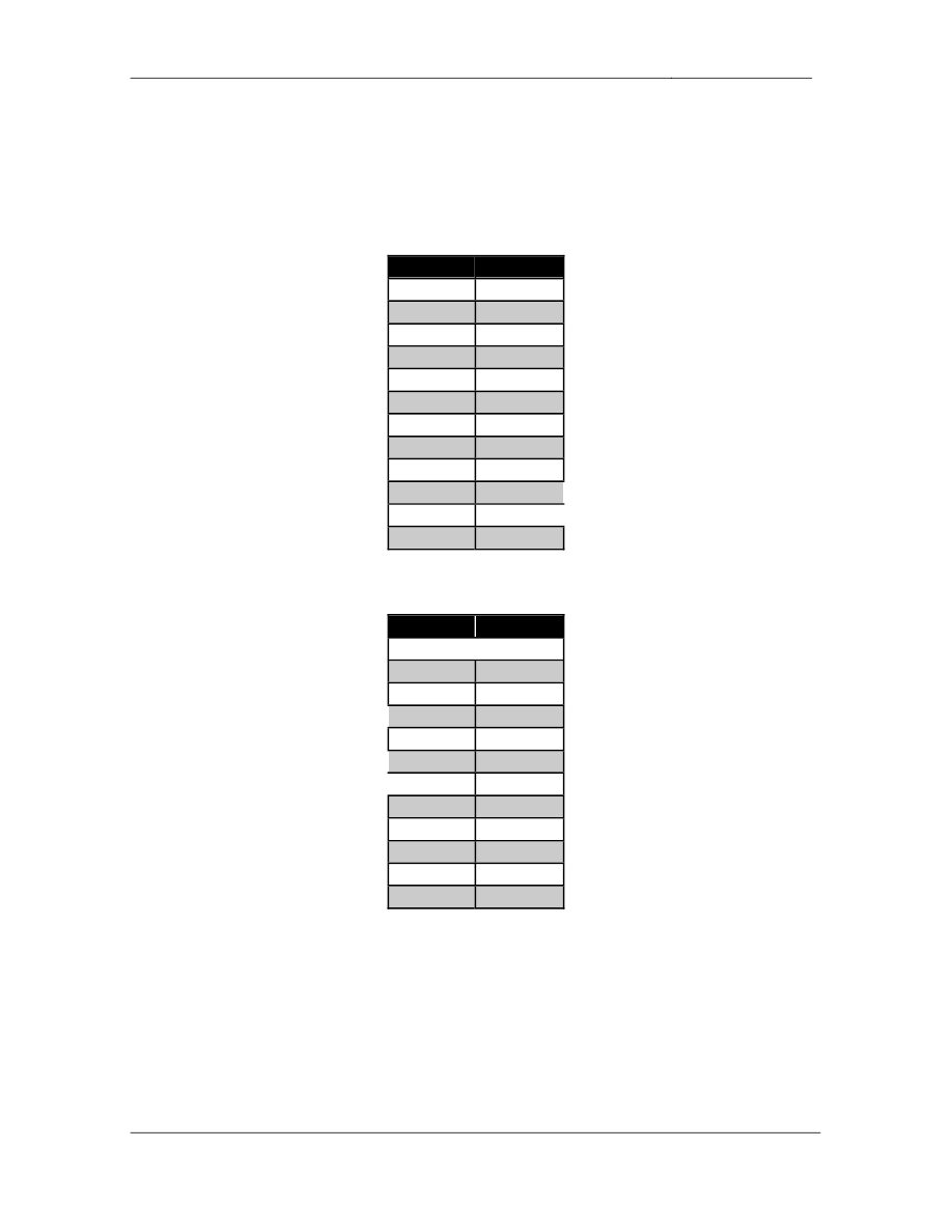
Point Values:
The point values for each section are as follows:
Section
Point Value
WAN Technologies
9
Bridging & Switching
16
Interior Gateway Routing
20
Exterior Gateway Routing
10
IP Multicast
9
IPv6
12
QoS
8
Security
6
System Management
6
IP Services
4
GOOD LUCK!

CCIE Routing & Switching Lab Workbook Version 4.0
Lab 5
Copyright © 2007 Internetwork Expert
www.InternetworkExpert.com
- 105 -
Troubleshooting
• There
are
two
issues
with
the
initial
configurations
applied
to
the
devices.
• These
issues
will
be
to
be
resolved
in
order
to
complete
certain
tasks.
• Each
issue
is
worth
1
point.
1. WAN Technologies
1.1. Partial Mesh Frame Relay
• Configure
a
partially
meshed
Frame
Relay
network
between
R2,
R3,
R4,
and R5 using only the DLCIs specified in the diagram.
• Do
not
use
subinterfaces
on
R3,
R4,
or
R5.
• Use
a
subinterface
.1 on R2.
• Do
not
use
any
dynamic
Frame
Relay
mappings
on
any
of
these
circuits.
• Do
not
use
any
static
Frame
Relay
mappings
on
R2.
• Traffic
from
R5
destined
for
R2
should
transit
R4.
• All
other
traffic
should
take
the
most
direct
path
through
the
Frame
Relay
network.
3 Points
1.2. Point-to-Point Frame Relay
• Using
only
physical
interfaces
configure
a
Frame
Relay
connection
between R1 and R3.
• Do
not
use
Frame
Relay
Inverse-ARP.
2 Points
1.3. Point-to-Point Frame Relay
• Configure
the
Frame
Relay
connection
between
R6
and
BB1
to
reflect
the
following output:
Rack1R6#show frame-relay map
Serial0/0/0.1 (up): ip 54.X.1.254 dlci 101(0x65,0x1850), dynamic,
broadcast,, status defined, active
2 Points

CCIE Routing & Switching Lab Workbook Version 4.0
Lab 5
Copyright © 2007 Internetwork Expert
www.InternetworkExpert.com
- 106 -
1.4. PPP
• Configure
PPP
encapsulation
on
the
point-to-point
Serial
link
between
R4
and R5.
• Recent
network
monitoring
has
shown
intermittent
packet
loss
on
this
link.
While this problem is investigated further with the service provider
configure R4 and R5 to support reliable transport over the circuit.
2 Points
2. Bridging & Switching
2.1. VLAN Assignments
• Configure
the
VTP
domain
CCIE
on
SW1,
SW2,
SW3,
and
SW4.
• The
switches
should
be
able
to
create,
delete,
and
modify
VLANs
locally
but they should not propagate these updates to other switches.
• VLANs
should
not
be
applied
to
switches
unnecessarily.
• Create
and
configure
the
VLAN
assignments
as
follows:
3 Points
Catalyst Port
Interface
VLAN
SW1 Fa0/1
R1 Fa0/0
162
SW1 Fa0/3
R3 E0/0
38
SW1 Fa0/5
R5 E0/0
2005
SW1 Fa0/15
SW2 Fa0/15
38
SW2 Fa0/2
R2 Fa0/0
27
SW2 Fa0/4
R4 E0/0
4
SW2 Fa0/6
R6 G0/0
162
SW2 Fa0/15
SW1 Fa0/15
Routed
SW2 Fa0/24
BB2
162
SW3 Fa0/3
R3 E0/1
3
SW3 Fa0/5
R5 E0/1
55
SW3 Fa0/24
BB3
4
SW4 Fa0/6
R6 G0/1
6

CCIE Routing & Switching Lab Workbook Version 4.0
Lab 5
Copyright © 2007 Internetwork Expert
www.InternetworkExpert.com
- 107 -
2.2. EtherChannel
• Configure
an
EtherChannel
link
between
SW1’s
interfaces
Fa0/13
and
Fa0/14 and SW2’s interfaces Fa0/13 and Fa0/14. Use port channel
number 12.
• Configure
an
EtherChannel
link
between
SW1’s
interfaces
Fa0/16
and
Fa0/17 and SW3’s interfaces Fa0/13 and Fa0/14. Use port channel
number 13.
• Configure
an
EtherChannel
link
between
SW1’s
interfaces
Fa0/19
and
Fa0/20 and SW4’s interfaces Fa0/13 and Fa0/14. Use port channel
number 14.
• Do
not
run
PAgP
or
LACP
on
these
links.
• All
traffic
sent
over
these
trunk
links
should
be
tagged
with
a
VLAN
header.
• Do
not
issue
any
global
configuration
commands
to
accomplish
this
task.
4 Points
2.3. Load Distribution
• You
have
noticed
very
high
utilization
on
the
interface
Fa0/13
between
SW1 and SW2 and have determined that the majority of the traffic
transiting this link is coming from a single file server located behind BB2.
• Traffic
is
sourced
from
multiple
clients
behind
R1
and
R6.
• Configure
the
network
in
such
a
way
that
traffic
sent
over
this
EtherChannel link is distributed more evenly while taking into account the
single server and multiple clients.
3 Points
2.4. CAM Table Maintenance
• Administrators
of
your
network
have
noticed
that
some
traffic
has
been
leaking between VLAN 8 and VLAN 88. After further investigation, you
have determined that SW2’s CAM table is maxed out and has been
treating some unicast frames like broadcast frames.
• In
order
to
reduce
the
amount
of
entries
in
the
CAM
table
configure
the
network so that SW2 discards inactive entries from VLAN 8 and VLAN 88
after 10 seconds.
2 Points

CCIE Routing & Switching Lab Workbook Version 4.0
Lab 5
Copyright © 2007 Internetwork Expert
www.InternetworkExpert.com
- 108 -
2.5. EtherChannel
• Configure
a
layer
3
EtherChannel
link
between
SW1’s
interface
Fa0/21
and SW4’s interface Fa0/15. Use port channel number 41.
• Configure
a
layer
3
EtherChannel
link
between
SW2’s
interfaces
Fa0/16
-
18 and SW3’s interfaces Fa0/16 - 18. Use port channel number 32.
• Configure
a
layer
3
EtherChannel
link
between
SW3’s
interfaces
Fa0/19
-
21 and SW4’s interfaces Fa0/19 - 21. Use port channel number 43.
• Use
LACP
on
these
links.
• Apply
the
IP
addressing
for
the
Etherchannel
links
from
the
diagram.
4 Points
3. Interior Gateway Routing
3.1. OSPF
• Configure
OSPF
area
0
on
the
Frame
Relay
connection
between
R2,
R3,
R4, & R5, and on VLANs 55 and 2005 of R5.
• Do
not
use
the
ip ospf network command on R3.
• Advertise
the
Loopback
0
interfaces
of
R2,
R3,
R4,
and
R5
into
OSPF
area 0.
3 Points
3.2. OSPF
• Configure
OSPF
area
27
on
the
Ethernet
segment
between
R2
and
SW1.
• Advertise
SW1’s
interface
Loopback
0
into
OSPF
area
27.
• Since
SW1’s
only
connection
to
the
rest
of
the
routing
domain
is
through
R2, SW1 does not need specific routing information about the rest of the
network. Configure your network so that the only OSPF route SW1 sees
is a default route generated by R2.
3 Points

CCIE Routing & Switching Lab Workbook Version 4.0
Lab 5
Copyright © 2007 Internetwork Expert
www.InternetworkExpert.com
- 109 -
3.3. EIGRP
• Configure
EIGRP
AS
200
on
R1,
R3,
and
SW2.
• Enable
EIGRP
on
the
Frame
Relay
segment
between
R1
and
R3.
• Enable
EIGRP
on
VLAN
3
and
VLAN
38
on
R3.
• Advertise
the
Loopback
0
interface
of
R1
into
the
EIGRP
domain.
• Enable
EIGRP
on
all
interfaces
of
SW2,
but
do
not
use
redistribution
or
more than one network statement to accomplish this.
2 Points
3.4. EIGRP
• One
of
the
deciding
factors
in
choosing
EIGRP
as
an
IGP
for
your
network
was the granularity of its metric calculation.
• In
order
to
get
the
maximum
benefit
of
this
granularity
configure
the
EIGRP domain so that bandwidth, delay, and load are taken into account
when computing metrics.
• Also
to
ensure
that
bandwidth
is
always
the
major
factor
in
metric
calculation, configure the EIGRP domain so that bandwidth is three times
more significant than either load or delay in the calculation.
2 Points
3.5. Default Routing
• The
only
connection
between
the
EIGRP
domain
and
the
OSPF
domain
is
through R3. Therefore in order to minimize the memory requirements
throughout the OSPF domain configure your network so that R3
advertises a default route to the rest of your OSPF enabled devices.
• In
order
to
help
prevent
traffic
black
holes
ensure
that
R3
drops
traffic
for
all destinations it does not have a longer match for.
2 Points

CCIE Routing & Switching Lab Workbook Version 4.0
Lab 5
Copyright © 2007 Internetwork Expert
www.InternetworkExpert.com
- 110 -
3.6. Routing Redundancy
• Your
network
administrators
are
concerned
with
a
failure
of
R5’s
Frame
Relay link isolating it from the rest of the network. In order to prevent this
case an additional point-to-point Serial link has been provisioned to R4.
• Configure
the
network
in
such
a
way
that
connectivity
is
maintained
throughout the network if R5 loses its connection to the Frame Relay
cloud.
• You
are
allowed
to
use
static
routes
to
accomplish
this
task.
2 Points
3.7. RIPv2
• Configure
RIPv2
on
R1,
R4,
and
R6.
• Enable
RIP
on
VLAN
4,
VLAN
162,
and
the
Frame
Relay
connection
to
BB1.
• Enable
RIP
on
R6’s
interface
Loopback
0.
• Administrators
of
your
network
are
concerned
about
false
routing
information being injected into the RIP domain from VLAN 162. In order to
prevent this configure R1 and R6 to authenticate all RIP updates received
on VLAN 162 with a secure hash value of the password CISCO. Use key
1 for this authentication.
• As
an
additional
security
precaution
configure
R1
and
R6
so
that
no
unauthorized devices can receive RIP updates sent out on VLAN 162.
3 Points
3.8. IGP Redistribution
• Redistribute
in
the
minimum
places
necessary
to
gain
full
reachability
throughout the network.
• Routers
in
the
OSPF
domain
should
have
the
minimum
amount
of
routes
needed to reach the RIP routes learned from BB3.
• Do
not
overlap
any
address
space
to
accomplish
this.
3 Points
CCIE Routing & Switching Lab Workbook Version 4.0
Lab 5
Copyright © 2007 Internetwork Expert
www.InternetworkExpert.com
- 111 -
4. Exterior Gateway Routing
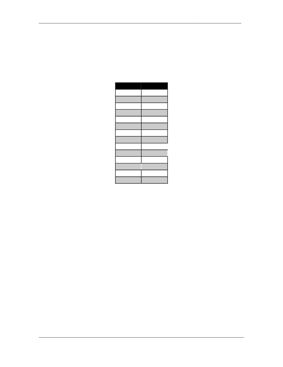
4.1. BGP Peering
• Configure
BGP
on
the
following
devices
with
the
following
AS
numbers:
Device
BGP AS
R1
200
R2
300
R3
300
R4
100
R5
500
R6
200
SW1
65001
SW2
65002
SW3
65034
SW4
65034
BB2
254
BB3
54
• Configure
the
BGP
peering
sessions
as
follows:
Device 1
Device 2
R4
BB3
R4
R5
R4
R3
R3
R2
R3
SW2
R3
R1
R2
SW1
R1
R6
R1
BB2
SW1
SW4
SW2
SW3
SW3
SW4
• Configure
SW3
and
SW4
to
advertise
their
Loopback0
interfaces
into
BGP.
• The
BGP
peering
session
between
R4
and
R5
should
remain
up
if
R5
loses its connection to the Frame Relay cloud.
• Configure
R1
to
authenticate
its
BGP
peering
session
with
BB2
using
the
password CISCO.
2 Points

CCIE Routing & Switching Lab Workbook Version 4.0
Lab 5
Copyright © 2007 Internetwork Expert
www.InternetworkExpert.com
- 112 -
4.2. AS-Path Manipulation
• Create
a
new
Loopback
interface
on
SW1
with
the
IP
address
162.X.7.7/24 and advertise it into BGP.
• Create
a
new
Loopback
interface
on
SW2
with
the
IP
address
162.X.18.8/24 and advertise it into BGP.
• Since
SW1,
SW2,
SW3,
and
SW4
only
have
a
single
connection
to
AS
300 it has been decided that they will not apply for their own block of IP
addresses, nor will they apply for a public BGP AS number. Instead, AS
300 has assigned them the locally significant AS numbers of 65001,
65002, and 65034.
• Configure
your
network
so
these
AS
numbers
do
not
leak
out
onto
the
rest
of the network when AS 300 is advertising prefixes that have been
originated in either AS 65001, AS 65002, or AS 65034.
2 Points
4.3. BGP Filtering
• Configure
a
new
Loopback
interface
on
R5
with
the
IP
address
162.X.15.5/24 and advertise it into BGP.
• R4
should
not
pass
this
prefix
on
to
any
BGP
speaking
neighbors.
• All
of
this
configuration
should
be
done
on
R5.
3 Points
4.4. BGP Table Stability
• Recent
network
monitoring
has
shown
excessive
route
recalculation
throughout the BGP domain. After further investigation you have found
that AS 54’s uplinks to the rest of the Internet have become unstable, and
routes are constantly being added and withdrawn from their
advertisements.
• To
minimize
the
impact
on
the
rest
of
the
network
configure
R4
to
add
a
penalty of 1000 to BGP prefixes each time a withdrawn message is
received for them.
• R4
should
stop
advertising
these
unstable
prefixes
when
their
penalty
value exceeds 3000.
• Once
a
stable
prefix’s
penalty
falls
below
1000
it
should
be
reinstalled
in
the BGP table as an active prefix.
• Ensure
that
no
stable
prefix’s
advertisement
is
withdrawn
for
more
than
30
minutes.
3 Points
CCIE Routing & Switching Lab Workbook Version 4.0
Lab 5
Copyright © 2007 Internetwork Expert
www.InternetworkExpert.com
- 113 -
5. IP Multicast
5.1. PIM
• Configure
IP
Multicast
routing
on
R1,
R2,
R3,
R5,
and
SW2.
• Configure
PIM
on
the
following
interfaces:
Device
Interface
R1
Fa0/0
R1
S0/0
R2
Fa0/0
R2
S0/0.1
R3
E0/0
R3
E0/1
R3
S1/0
R3
S1/1
R5
E0/0
R5
E0/1
R5
S0/0
SW2
Fa0/15
SW2
VL8
SW2
VL88
• Multicast
groups
without
an
active
RP
should
run
in
dense
mode.
2 Points
5.2. RP Assignment
• Configure
R3
to
announce
its
Loopback
0
interface
as
a
candidate
rendezvous-point (RP) through Auto-RP.
• Configure
R5
to
announce
its
Loopback
0
interface
as
a
candidate
rendezvous-point (RP) through Auto-RP.
• For
ease
of
management
and
future
multicast
configuration
changes
configure R1 to map multicast groups 239.0.0.0 – 239.255.255.255 to R3
and multicast groups 226.0.0.0 – 238.255.255.255 to R5.
• Use
the
minimum
number
of
access-lists
and
access-list
entries
on
R1
to
accomplish this.
3 Points

CCIE Routing & Switching Lab Workbook Version 4.0
Lab 5
Copyright © 2007 Internetwork Expert
www.InternetworkExpert.com
- 114 -
5.3. Multicast Security
• For
security
reasons
do
not
allow
BB2
to
become
a
PIM
neighbor
with
R1.
2 Points
5.4. Multicast Filtering
• Configure
your
network
so
that
SW2
will
not
receive
traffic
for
any
administratively scoped multicast groups regardless of any IGMP join
messages it receives for these groups.
1 Point
5.5. Multicast Distribution
• Configure
the
network
so
that
multicast
groups
which
use
R3
as
their
RP
cannot build a shortest path source tree. Instead these multicast groups
should always use a shared tree.
2 Point
6. IPv6
6.1. IPv6 Addressing
• Enable
IPv6
processing
on
R1,
R2,
R3,
and
R4.
• Configure
IPv6
on
R1’s
connection
to
VLAN
162
using
the
address
2001:CC1E:X:1::1/64.
• Configure
IPv6
on
R2’s
connection
to
VLAN
27
using
the
address
2001:CC1E:X:2::2/64.
• Configure
IPv6
on
R3’s
connection
to
VLAN
3
using
the
address
2001:CC1E:X:3::3/64.
• Configure
IPv6
on
R4’s
connection
to
VLAN
4
using
the
address
2001:204:12:X::100/64.
2 Points

CCIE Routing & Switching Lab Workbook Version 4.0
Lab 5
Copyright © 2007 Internetwork Expert
www.InternetworkExpert.com
- 115 -
6.2. IPv6 over Frame Relay
• Configure
IPv6
on
the
Frame
Relay
link
between
R1
and
R3
using
the
global unicast network 2001:CC1E:X:0::Y/64.
• Configure
IPv6
on
the
Frame
Relay
links
between
R2,
R3,
and
R4
using
the site-local network FEC0:234::Y/64.
2 Points
6.3. IPv6 BGP
• Configure
IPv6
BGP
peering
sessions
between
the
following
devices:
Device 1
Device 2
R4
BB3
R4
R3
R3
R2
R3
R1
3 Points
6.4. IPv6 BGP Advertisements
• Configure
R1,
R2,
and
R4
to
advertise
IPv6
networks
of
VLANs
162,
27,
and 4 into BGP respectively.
• Configure
R3
to
advertise
the
IPv6
Frame
Relay
segments
and
VLAN
3
into BGP.
2 Points
6.5. IPv6 BGP Summarization
• Configure
R3
so
that
R4
and
BB3
only
see
one
route
to
VLANs
3,
27,
162,
and the Frame Relay link between R1 and R3.
• The
advertisement
should
be
as
specific
as
possible
while
still
encompassing all of these segments.
• R1
and
R2
should
not
be
affected
by
this
configuration.
3 Points

CCIE Routing & Switching Lab Workbook Version 4.0
Lab 5
Copyright © 2007 Internetwork Expert
www.InternetworkExpert.com
- 116 -
7. QoS
7.1. Frame Relay Traffic Shaping
• Administrators
in
your
NOC
have
noticed
an
excessive
amount
of
packet
loss across the Frame Relay cloud between R1 and R3. After further
investigation these engineers have determined that R1 has been
overwhelming the Frame Relay connection to R3.
• Configure
Frame
Relay
Traffic
Shaping
on
R1
in
order
to
help
resolve
this
issue.
• R1
has
a
port
speed
of
512Kbps.
• R1’s
DLCI
113
has
a
provisioned
CIR
of
256Kbps.
• R1
should
send
data
at
384Kbps
and
throttle
down
to
CIR
in
the
event
of
congestion notification from the Frame Relay cloud.
• In
the
case
that
R1
has
accumulated
credit
it
should
be
allowed
to
burst
up to its port speed.
• Use
an
interval
(Tc)
of
100ms.
3 Points
7.2. RTP Header Compression
• Configure
the
Frame
Relay
connection
between
R3
and
R4
to
support
RTP header compression.
• This
compression
should
support
up
to
15
connections.
• R3
should
only
compress
RTP
headers
if
it
is
receiving
RTP
headers
that
are compressed.
• R3
should
not
perform
RTP
header
compression
with
any
other
routers.
2 Points

CCIE Routing & Switching Lab Workbook Version 4.0
Lab 5
Copyright © 2007 Internetwork Expert
www.InternetworkExpert.com
- 117 -
7.3. Bandwidth Limiting
• Users
have
been
complaining
about
slow
access
to
servers
in
VLAN
27.
After further investigation one of your network administrators has reported
that the congestion appears to be caused by users accessing a Microsoft
SQL server in that VLAN.
• To
resolve
this
problem
configure
your
network
so
that
Microsoft
SQL
traffic is limited to an average rate of 256Kbps on R2’s connection to the
Frame Relay cloud.
• Up
to
2048
SQL
packets
in
excess
of
256Kbps
should
be
queued
up
by
R2 before packet loss occurs.
• Do
not
use
an
access-list
to
accomplish
this.
3 Points
8. Security
8.1. Traffic Filtering
• A
new
corporate
policy
has
been
put
in
to
effect
that
requires
R4
to
secure
its connection to BB3. R4 should treat its interface connecting to BB3 as
an ‘outside’ interface and all other links as ‘inside’ interfaces.
• Any
ICMP,
UDP,
or
TCP
traffic
coming
in
from
an
inside
interface
and
exiting the outside interface should be allowed to return.
• R4
should
still
allow
all
necessary
routing
protocol
traffic
in
from
the
outside interface.
• For
management
purposes
R4
will
need
to
be
able
to ping
and
telnet
to
BB3.
3 Points
8.2. DoS Prevention
• Recently
R1
and
R6
underwent
a
ping
DoS
attack
that
originated
from
behind BB2. In response to this your network administrator has requested
you to configure R1 and R6 to not receive any ICMP echo requests
sourced from the 205.90.31.0/24 network inbound on their interfaces
attached to VLAN 162.
• Do
not
apply
any
configuration
on
either
R1
or
R6
to
accomplish
this.
3 Points

CCIE Routing & Switching Lab Workbook Version 4.0
Lab 5
Copyright © 2007 Internetwork Expert
www.InternetworkExpert.com
- 118 -
9. System Management
9.1. SNMP
• A
new
network
management
server
has
been
installed
to
manage
R6.
Configure R6 using the following SNMP parameters:
o
Contact:
CCIE
Lab
R6
o
Location:
San
Jose,
CA
US
o
Chassis
ID:
556-123456
o
Read-Only
community:
CISCORO
o
Read-Write
community:
CISCORW
• The
management
station’s
IP
address
is
192.10.X.101.
• This
is
the
only
station
that
should
be
allowed
to
manage
R6.
• Attempts
by
other
devices
to
manage
R6
via
SNMP
should
be
logged.
• The
network
management
server
will
be
expecting
SNMP
traps
to
use
a
community of CISCOTRAP and be sourced from R6’s Loopback 0
interface.
3 Points
9.2. Syslog
• One
of
your
network
administrators
has
requested
that
R4
and
R5
be
configured to log all severity 5 and below messages to a syslog server
with the IP address 192.10.X.101.
• This
network
administrator
has
configured
the
syslog
server
to
expect
these messages to use the sys10 facility.
• R4
and
R5
should
include
their
hostname
in
the
syslog
messages.
• All
syslog
messages
should
be
sourced
from
R4
and
R5’s
Loopback
0
interfaces.
3 Points

CCIE Routing & Switching Lab Workbook Version 4.0
Lab 5
Copyright © 2007 Internetwork Expert
www.InternetworkExpert.com
- 119 -
10. IP Services
10.1. DNS
• The
network
administrators
have
requested
that
they
should
be
able
to
telnet to the routers in your network using their DNS names as opposed to
their IP addresses while working on R6. The network administrator has
setup a DNS server at IP address 192.10.X.100 for R6 to point to for DNS
resolution.
• Ensure
that
if
your
administrators
mistype
a
command
when
working
on
the console the router it does not try to resolve the mistyped command via
DNS.
• This
configuration
should
not
affect
any
other
lines
on
R6.
2 Points
10.2. Local Authorization
• The
first
level
support
engineers
from
the
company’s
NOC
have
complained to management about not having access to view R6’s running
configuration.
• To
appease
them
configure
R6
so
that
these
users
can
see
only
the
following information in the running configuration:
o
Hostname
o
Interfaces
o
Interface
encapsulations
o
IP
access-lists
applied
to
interfaces
• The
NOC
users
must
enter
privilege
level
2
using
the
password
CISCO
prior to being able to view the configuration.
2 Points

CCIE Routing & Switching Lab Workbook Version 4.0
Lab 5
Copyright © 2007 Internetwork Expert
www.InternetworkExpert.com
- 120 -
Wyszukiwarka
Podobne podstrony:
lab 7 overview
lab 3 overview
Lab 6 overview id 258166 Nieznany
Lab 1 overview
IE RS lab 9 overview
lab 7 overview
Lab 2 overview
Lab 6 overview
IE RS lab 18 overview
IE RS Lab 16 overview
IE RS lab 17 overview
IE RS lab 10 overview
IE RS lab 11 overview
IE RS lab 20 overview
IE RS lab 13 overview
IE RS lab 15 overview
IE RS lab 19 overview
więcej podobnych podstron