
-
CCIE Routing & Switching Lab Workbook Version 4.0
Lab 11
Copyright © 2007 Internetwork Expert
www.InternetworkExpert.com
- 215 -
IEWB-RS Lab 11
Difficulty Rating (10 highest): 9
Lab Overview:
The following scenario is a practice lab exam designed to test your skills at
configuring Cisco networking devices. Specifically, this scenario is designed to
assist you in your preparation for Cisco Systems’ CCIE Routing and Switching
Lab exam. However, remember that in addition to being designed as a
simulation of the actual CCIE lab exam, this practice lab should be used as a
learning tool. Instead of rushing through the lab in order to complete all the
configuration steps, take the time to research the networking technology in
question and gain a deeper understanding of the principles behind its operation.
Lab Instructions:
Prior to starting, ensure that the initial configuration scripts for this lab have been
applied. For a current copy of these scripts, see the Internetwork Expert
members site at
http://members.internetworkexpert.com
Refer to the attached diagrams for interface and protocol assignments. Any
reference to X in an IP address refers to your rack number, while any reference
to Y in an IP address refers to your router number.
Upon completion, all devices should have full IP reachability to all networks in the
routing domain, including any networks generated by the backbone routers
unless explicitly specified.
Lab Do’s and Don’ts:
• Do
not
change
any
IP
addresses
from
the
initial
configuration
unless
otherwise specified
• Do
not
change
any
interface
encapsulations
unless
otherwise
specified
• Do
not
change
the
console,
AUX,
and
VTY
passwords
or
access
methods
unless otherwise specified
• Do
not
use
any
static
routes,
default
routes,
default
networks,
or
policy
routing unless otherwise specified
• Save
your
configurations
often
-
CCIE Routing & Switching Lab Workbook Version 4.0
Lab 11
Copyright © 2007 Internetwork Expert
www.InternetworkExpert.com
- 216 -
Grading:
This practice lab consists of various sections totaling 100 points. A score of 80
points is required to achieve a passing score. A section must work 100% with the
requirements given in order to be awarded the points for that section. No partial
credit is awarded. If a section has multiple possible solutions, choose the solution
that best meets the requirements.
Grading for this practice lab is available when configured on Internetwork
Expert’s racks, or the racks of Internetwork Expert’s preferred vendors. See
Internetwork Expert’s homepage at
http://www.internetworkexpert.com
for more
information.
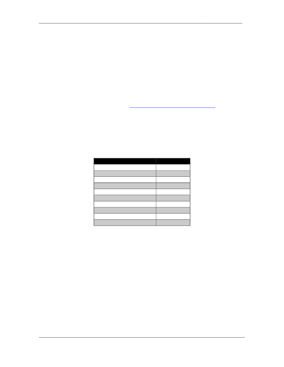
Point Values:
The point values for each section are as follows:
Section
Point Value
Bridging & Switching
18
WAN Technologies
11
Interior Gateway Routing
24
Exterior Gateway Routing
9
IP Multicast
9
IPv6
12
QoS
3
Security
3
System Management
6
IP Services
5
GOOD LUCK!

-
CCIE Routing & Switching Lab Workbook Version 4.0
Lab 11
Copyright © 2007 Internetwork Expert
www.InternetworkExpert.com
- 217 -
1. Bridging & Switching
1.1.
• Configure
the
VTP
domain
INTEXP
between
SW1,
SW2,
and
SW3.
• Authenticate
the
VTP
domain
with
the
password
CISCO.
• All
VLAN
configuration
commands
should
be
applied
on
SW1.
• SW2
and
SW3
should
not
be
allowed
to
create
or
modify
any
VLAN
parameters.
• Create
and
configure
the
VLAN
assignments
as
follows:
Catalyst Port
Interface
VLAN
SW1 Fa0/1
R1 - Fa0/0
17
SW1 Fa0/2
R2 - Fa0/0
23
SW1 Fa0/3
R3 - E0/0
3
SW1 Fa0/4
R4 - E0/0
4
SW1 Fa0/5
R5 - E0/0
5
SW1 Fa0/6
R6 - G0/0
56
SW1 Fa0/7
7960 IP Phone
7
SW1 Fa0/8
7960 IP Phone
7
SW1
VLAN 7
7
SW1
VLAN 17
17
SW2 Fa0/4
R4 - E0/1
N/A
SW2 Fa0/24
BB2
28
SW2
VLAN 28
28
SW2
VLAN 38
38
SW3 Fa0/3
R3 - E0/1
38
SW3 Fa0/5
R5 - E0/1
56
SW3 Fa0/24
BB3
23
2 Points
1.2.
• Configure
three
dot1q
trunks
between
SW1’s
interfaces
Fa0/13,
14,
&
15,
and SW2’s interfaces Fa0/13, 14, & 15.
• Configure
a
dot1q
trunk
between
SW1’s
interfaces
Fa0/16
and
SW3’s
interfaces Fa0/13.
• Configure
a
dot1q
trunk
between
SW2’s
interfaces
Fa0/16
and
SW3’s
interfaces Fa0/16.
• Do
not
use
the
switchport mode trunk command to accomplish this.
2 Points

-
CCIE Routing & Switching Lab Workbook Version 4.0
Lab 11
Copyright © 2007 Internetwork Expert
www.InternetworkExpert.com
- 218 -
1.3.
• Configure
SW1
as
the
spanning-tree
root
for
all
even
numbered
VLANs.
• Configure
SW2
as
the
spanning-tree
root
for
all
odd
numbered
VLANs.
• This
configuration
should
be
done
only
on
SW1.
2 Points
1.4.
• Configure
SW1
so
that
all
even
numbered
VLANs
prefer
the
Fa0/14
trunk
link over the Fa0/13 and Fa0/15 trunks.
• In
the
event
of
Fa0/14’s
failure
all
even
numbered
VLANs
should
switch
over to the Fa0/15 trunk.
• Even
numbered
VLANs
should
only
use
the
Fa0/13
trunk
in
the
event
that
both Fa0/14 and Fa0/15 fail.
• Do
not
apply
any
configuration
commands
on
SW1’s
interface
Fa0/13
or
any interface of SW2 in order to accomplish this task.
2 Points
1.5.
• Configure
SW1
so
that
all
odd
numbered
VLANs
prefer
the
Fa0/15
trunk
link over the Fa0/13 and Fa0/14 trunks.
• In
the
event
of
Fa0/15’s
failure
all
odd
numbered
VLANs
should
switch
over to the Fa0/13 trunk.
• Odd
numbered
VLANs
should
only
use
the
Fa0/14
trunk
in
the
even
that
both Fa0/13 and Fa0/15 fail.
• Do
not
apply
any
configuration
commands
on
SW1’s
interface
Fa0/14
or
any interface of SW2 in order to accomplish this task.
2 Points

-
CCIE Routing & Switching Lab Workbook Version 4.0
Lab 11
Copyright © 2007 Internetwork Expert
www.InternetworkExpert.com
- 219 -
1.6.
• A
recent
security
breach
which
involved
the
compromising
of
the
company’s future business plans was tracked down to a notebook
computer that was located in VLAN 28 with a MAC address of
0001.02ac.9ab2. After checking the MAC address tables of SW1 and
SW2 you have determined that the notebook computer is not currently
plugged into the network.
• In
order
to
help
track
down
this
device
in
the
future
configure
SW2
to
notify the network management station at 187.X.3.100 whenever a new
MAC address is learned in VLAN 28.
• The
network
management
server
will
be
expecting
community-string
to
be
CISCOTRAP.
2 Points
1.7.
• After
numerous
attempts
to
get
the
company’s
graphics
department
to
migrate their legacy servers to IP you have decided configure the network
to only allow IPv4 traffic and necessary layer 2 traffic to transit VLAN 56.
• Use
a
named
ACL
called
IPONLY
to
accomplish
this.
3 Points
1.8.
• Interfaces
Fa0/7
and
Fa0/8
on
SW1
connect
to
Cisco
7960
IP
phones.
• VoIP
originating
from
these
phones
is
being
marked
with
a
CoS
of
5.
• This
VoIP
traffic
should
belong
to
VLAN
7.
• Traffic
coming
from
the
PCs
connected
to
the
access
ports
of
these
IP
phones should belong to VLAN 17.
• Ensure
that
all
traffic
originating
from
the
IP
phones
maintains
its
CoS
values while transiting your switched network, while traffic coming from
their attached PCs is set to 0.
• For
ease
in
future
changes
of
these
interfaces
configure
SW1
so
that
these ports can be configured at the same time by using a macro named
VPORTS.
3 Points

-
CCIE Routing & Switching Lab Workbook Version 4.0
Lab 11
Copyright © 2007 Internetwork Expert
www.InternetworkExpert.com
- 220 -
2. WAN Technologies
2.1.
• Configure
a
Frame
Relay
hub-and-spoke
network
between
R1,
R3,
and
R4 with R3 as the hub.
• Use
a
multipoint
logical
interface
numbered
.134 on R1 and R4.
• Use
only
the
physical
interface
on
R3.
• R3
should
rely
on
Frame
Relay
Inverse-ARP
for
layer
3
to
layer
2
mappings to R1 and R4.
• Do
not
allow
R3
to
InARP
on
any
DLCIs
except
301
and
304.
• Do
not
send
unnecessary
broadcast
traffic
from
the
spokes
to
the
hub.
3 Points
2.2.
• Configure
a
Frame
Relay
full
mesh
between
R2,
R3,
and
R5.
• Use
a
logical
interface
numbered
235
on
R2
and
R3.
• Use
only
the
physical
interface
on
R5.
• Do
not
rely
on
Frame
Relay
InARP
for
layer
3
to
layer
2
mapping.
3 Points
2.3.
• Configure
the
Frame
Relay
connection
between
R6
and
BB1
using
the
PVC specified in the diagram.
• Do
not
use
subinterfaces
or
Frame
Relay
Inverse-ARP
on
R6
to
accomplish this.
2 Points
2.4.
• Configure
PPP
on
the
Serial
link
between
R4
and
R5.
• R4
should
challenge
R5
to
authenticate
with
CHAP.
• R5
should
respond
with
the
username
RackXR5
and
the
password
C1SC0?2000.
• Do
not
use
the
username command on R5 to accomplish this.
3 Points

-
CCIE Routing & Switching Lab Workbook Version 4.0
Lab 11
Copyright © 2007 Internetwork Expert
www.InternetworkExpert.com
- 221 -
3. Interior Gateway Routing
3.1.
• Configure
RIP
on
SW2.
• Enable
RIPv2
on
VLAN
28.
• Configure
MD5
authentication
on
the
RIP
session
between
SW2
and
BB2.
• Use
key
1
and
the
password
CISCO
for
this
authentication.
3 Points
3.2.
• Advertise
SW2’s
Loopback
0
interface
into
the
RIP
domain.
• Do
not
use
the
network command under the RIP process to accomplish
this.
• Do
not
advertise
any
other
interfaces
into
RIP
when
performing
this
task.
2 Points
3.3.
• Enable
OSPF
on
R1,
R3,
R4,
R5,
SW1,
and
SW2.
• Configure
these
devices
so
that
their
OSPF
router-IDs
will
always
be
their
Loopback 0 IP addresses even if the Loopback 0 interface is removed
from the device and the OSPF process is restarted.
• Configure
OSPF
area
0
on
VLANs
3,
4,
and
17.
• Configure
OSPF
area
38
on
VLAN
38.
• Configure
OSPF
area
7
on
VLAN
7
and
SW1
Fa0/18.
• Configure
OSPF
area
45
on
the
PPP
link
between
R4
and
R5.
3 Points

-
CCIE Routing & Switching Lab Workbook Version 4.0
Lab 11
Copyright © 2007 Internetwork Expert
www.InternetworkExpert.com
- 222 -
3.4.
• Configure
OSPF
area
134
on
the
Frame
Relay
cloud
between
R1,
R3,
and
R4.
• Configure
this
OSPF
network
in
such
a
way
that
R1
sees
OSPF
routes
advertised by R4 with a next hop value of R3, and vice versa.
• Ensure
that
R5,
SW1,
and
SW2
see
this
Frame
Relay
subnet
as
187.X.134.0/24.
3 Points
3.5.
• Advertise
the
Loopback
interfaces
of
R1,
R3,
R4,
and
SW1
into
OSPF
area 0.
• Advertise
SW2’s
interface
Loopback
0
into
OSPF
area
38
• Advertise
R5’s
interface
Loopback
0
into
OSPF;
This
network
should
not
be associated with any particular OSPF area.
• All
OSPF
devices
should
see
R5’s
Loopback
0
interface
with
an
OSPF
cost of 20.
2 Points
3.6.
• Using
the
password
of
CISCO
authenticate
the
OSPF
virtual
link
between
R3 and R4 using the strongest authentication method supported by OSPF.
• Do
not
authenticate
any
other
virtual
links
using
this
method.
• Using
the
password
of
CISCO
authenticate
the
OSPF
virtual
link
between
R1 and R3 using simple password authentication.
• Use
NULL
authentication
between
R1
and
SW1.
3 Points

-
CCIE Routing & Switching Lab Workbook Version 4.0
Lab 11
Copyright © 2007 Internetwork Expert
www.InternetworkExpert.com
- 223 -
3.7.
• Configure
EIGRP
AS
10
on
R2,
R3,
R5,
and
R6.
• Enable
EIGRP
on
VLANs
5
and
56.
• Advertise
the
Loopback
0
of
R2
into
EIGRP
via
the
network
statement.
• Advertise
the
Loopback
0
of
R6
into
EIGRP
via
redistribution.
• Enable
EIGRP
on
the
Frame
Relay
segment
between
R2,
R3,
and
R5.
• Ensure
that
connectivity
remains
throughout
the
EIGRP
domain
if
one
of
the circuits between R2, R3, and R5 goes down.
3 Points
3.8.
• Recent
network
monitoring
has
shown
an
excessive
exchange
of
EIGRP
query messages between R2, R3, and R5 when a route in the EIGRP
domain is lost.
• Configure
the
network
in
such
a
way
that
EIGRP
query
messages
are
not
sent to R2 in the event of a network failure anywhere in the EIGRP
domain.
2 Points
3.9.
• Redistribute
OSPF
into
RIP
on
SW2.
• Redistribute
between
EIGRP
and
OSPF
on
R3
and
R5.
• Routes
with
an
even
numbered
first
octet
should
be
redistributed
into
OSPF as E1; Odd routes should appear as E2 with a metric of 100.
3 Points
-
CCIE Routing & Switching Lab Workbook Version 4.0
Lab 11
Copyright © 2007 Internetwork Expert
www.InternetworkExpert.com
- 224 -
4. Exterior Gateway Routing
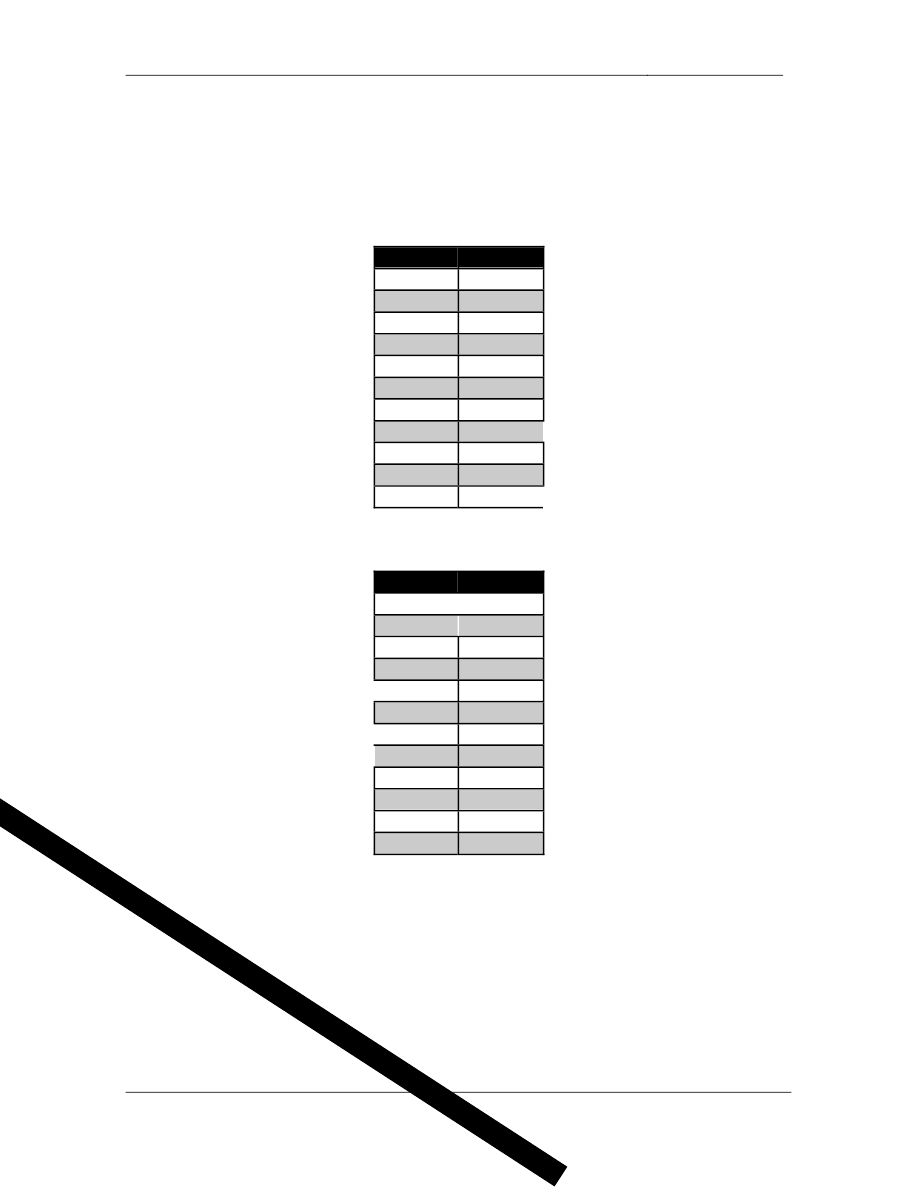
4.1.
• Configure
BGP
on
the
following
devices
with
the
following
AS
numbers:
Device
BGP AS
R1
65017
R2
100
R3
200
R4
200
R5
100
R6
100
SW1
65017
SW2
200
BB1
54
BB2
254
BB3
54
• Configure
the
BGP
peering
sessions
as
follows:
Device 1
Device 2
R1
R3
R1
SW1
R2
R3
R2
R5
R2
BB3
R3
R4
R3
R5
R3
SW2
R4
R5
R5
R6
R6
BB1
SW2
BB2
• Secure
the
BGP
session
between
SW2
and
BB2
using
the
password
CISCO.
2 Points

-
CCIE Routing & Switching Lab Workbook Version 4.0
Lab 11
Copyright © 2007 Internetwork Expert
www.InternetworkExpert.com
- 225 -
4.2.
• Create
a
new
Loopback
interface
on
SW1
with
the
IP
address
187.X.77.7/24 and advertise it into BGP.
• From
the
perspective
of
BGP
speaking
devices
outside
of
AS
200
this
prefix should appear to have originated in AS 200.
2 Points
4.3.
• Advertise
the
Frame
Relay
subnet
between
R2,
R3,
and
R5
(187.X.235.0/24) into BGP.
• Configure
R2
and
R6
to
advertise
a
single
route
representing
your
entire
primary network (187.X.0.0/16) to BB1 and BB3.
• To
ensure
that
AS
54
uses
R2
as
the
entry
point
for
the
187.X.235.0/24
prefix, configure R2 to continue sending the specific route 187.X.235.0/24
along the aggregate 187.X.0.0/16.
3 Points
4.4.
• Configure
SW2
to
advertise
its
interface
VLAN
28
along
with
any
routes
learned via RIP from BB2 into BGP.
• Do
not
use
redistribution
or
aggregation
to
accomplish
this.
2 Points

-
CCIE Routing & Switching Lab Workbook Version 4.0
Lab 11
Copyright © 2007 Internetwork Expert
www.InternetworkExpert.com
- 226 -
5. IP Multicast
5.1.
• Configure
IP
multicast
routing
on
R1,
R3,
R4,
R5,
and
SW1.
• Enable
PIM
sparse
mode
on
VLANs
3,
4,
5,
7,
and
17.
• Enable
PIM
sparse
mode
on
the
Frame
Relay
segments
between
R1,
R3,
& R4, and R2, R3, & R5.
3 Points
5.2.
• Configure
R4
to
announce
itself
as
the
RP
for
the
multicast
groups
224.0.0.0 – 231.255.255.255.
• Configure
R5
to
announce
itself
as
the
RP
for
the
multicast
groups
232.0.0.0 – 239.255.255.255.
• R3
should
be
responsible
for
group
to
RP
mappings.
• Do
not
use
Auto-RP
to
accomplish
this.
3 Points
5.3.
• One
of
your
network
administrators
has
informed
you
that
his
PC
in
VLAN
7 is unable to receive the multicast feed 228.34.28.100 that is being
originated from a server in VLAN 4.
• Configure
the
network
to
resolve
this
problem,
and
so
that
SW1
responds
to ICMP echo requests sent to 228.34.28.100 coming from VLAN 4.
• Do
not
use
the
ip pim nbma-mode command to accomplish this.
3 Points

-
CCIE Routing & Switching Lab Workbook Version 4.0
Lab 11
Copyright © 2007 Internetwork Expert
www.InternetworkExpert.com
- 227 -
6. IPv6
6.1.
• Configure
IPv6
on
the
Frame
Relay
segment
between
R6
and
BB1
using
the address 2001:54:254:X::Y/64.
• Enable
RIPng
on
this
segment.
3 Points
6.2.
• Configure
IPv6
on
VLAN
4
of
R4
using
the
network
2001:187:X:4::/64.
• Configure
IPv6
on
VLAN
17
of
R1
using
the
network
2001:187:X:17::/64.
• Configure
fully
meshed
IPv6
over
IPv4
tunnels
between
R1,
R4,
and
R6.
• Use
the
default
encapsulation
for
these
tunnels,
and
addressing
in
the
format 2001:187:X:AB::/64 where “A” is the lower of the routers’ numbers
and “B” is the higher.
3 Points
6.3.
• Enable
RIPng
on
VLANs
4,
17,
and
the
IPv6
over
IPv4
tunnels.
• BB1
should
see
the
single
route
2001:187:X::/48
representing
your
entire
IPv6 address space.
3 Points
6.4.
• Configure
the
network
in
such
a
way
that
IPv6
traffic
from
VLAN
17
going
to BB1 is first sent to R4, and then on to R6.
• Traffic
from
BB1
back
to
R1
should be
sent
directly
from
R6
to
R1.
• Do
not
use
the
metric-offset command to accomplish this.
3 Points

-
CCIE Routing & Switching Lab Workbook Version 4.0
Lab 11
Copyright © 2007 Internetwork Expert
www.InternetworkExpert.com
- 228 -
7. QoS
7.1.
• After
recent
connectivity
issues
between
R1,
R3,
and
R4
you
have
noticed
that a large percentage of frames arriving from R3 have the DE bit set.
After discussing this issue with the Frame Relay service provider’s
helpdesk they have recommended that Frame Relay Traffic Shaping be
enabled on R3.
• Configuring
FRTS
on
R3
according
to
the
following
parameters:
o
R3’s
connection
to
the
Frame
Relay
cloud
has
a
port
speed
of
512Kbps.
o
A
CIR
of
192Kbps
was
subscribed
with
the
Frame
Relay
service
provider for DLCI 301 and 304.
o
Allow
either
DLCI
to
burst
above
CIR
if
credit
is
available.
o
To
help
ensure
that
one
DLCI
does
not
ever
consume
all
the
bandwidth only allow bursts up to 320Kbps for a maximum period
of 100ms.
3 Points
8. Security
8.1.
• Recently
a
CERT
security
advisory
was
released
that
reported
various
vulnerabilities in the version of IOS used in your network. In response to
this Cisco has recommended that IP protocols 53, 55, 77, and 103 be
denied from both entering and leaving the network.
• Configure
a
filtering
policy
on
R2,
R6,
and
SW2
to
reflect
these
new
recommendations.
• In
order
to
minimize
the
impact
of
this
filtering
policy
on
these
devices
ensure that TCP and UDP traffic is permitted prior to denying any other IP
protocols.
• Your
security
team
has
expressed
interested
in
the
amount
of
packets
that
are denied by this filtering policy and have requested that denied packets
be logged to a syslog server at 187.X.38.100.
• Configure
all
devices
to
reflect
this.
3 Points

-
CCIE Routing & Switching Lab Workbook Version 4.0
Lab 11
Copyright © 2007 Internetwork Expert
www.InternetworkExpert.com
- 229 -
9. System Management
9.1.
• Recently
users
were
unable
to
access
resources
from
BB1
due
to
the
fact
that one of your administrators misconfiguration an access-list on R6.
Unfortunately you are not sure which admin it was since logging wasn’t
enabled.
• To
avoid
this
problem
in
the
future
implement
a
change
control
policy
on
R6 which logs all commands entered to syslog.
• The
syslog
server’s
IP
address
is
187.X.5.155.
• In
the
case
that
the
syslog
server
is unavailable
R6
should
store
up
to
500
of these log entries locally.
3 Points
9.2.
• For
further
logging
accuracy
configure
R6
to
get
network
time
from
BB1.
• R6’s
time
zone
should
be
set
to
Pacific
time,
and
automatically
adjust
for
daylight savings time.
• Additionally
log
messages
sent
to
the
syslog
server
should
include
R6’s
local clock’s time to the millisecond.
3 Points

-
CCIE Routing & Switching Lab Workbook Version 4.0
Lab 11
Copyright © 2007 Internetwork Expert
www.InternetworkExpert.com
- 230 -
10. IP Services
10.1.
• Due
to
the
large
amount
of
time
that
some
of
your
coworkers
spend
browsing the Internet you have recommended to management that a web
cache engine be installed to enhance their Internet browsing experience.
As usual management has blindly taken your recommendation and
approves the purchase a web cache engine. Your coworkers that will
need to have their HTTP requests redirected to the web cache engine are
located in VLAN 3.
• Your
personal
Linux
workstation
is
also
located
in
VLAN
3.
Since
you
do
not have time to browse the Internet like some of your coworkers you have
decided to exclude your HTTP requests from being cached.
• Your
workstation’s
IP
address
is
187.X.3.50.
• Configure
R3
to
reflect
this
policy.
3 Points
10.2.
• You
have
been
informed
that
a
DHCP
server
will
be
installed
on
VLAN
56
to service hosts in VLANs 5 and 56, however you don’t know what the IP
address of the server will be.
• Configure
R5
to
forward
DHCP
requests
received
on
VLAN
5
to
this
server that will be located in VLAN 56.
2 Points
Wyszukiwarka
Podobne podstrony:
IE RS lab 11 solutions
IE RS lab 18 overview
IE RS lab 11 diagram
IE RS Lab 16 overview
IE RS lab 17 overview
IE RS lab 10 overview
IE RS lab 20 overview
IE RS lab 13 overview
IE RS lab 15 overview
IE RS lab 19 overview
IE RS lab 11 solutions
IE RS lab 9 overview
IE RS lab 10 solutions
IE RS lab 12 solutions
IE RS lab 18 Diagram
IE RS lab 9 solutions
IE RS lab 20 diagram
IE RS lab 19 diagram
IE RS lab 8 diagram
więcej podobnych podstron