
Accessed by arshadwasati@hotmail.com from 202.53.8.253 at 00:14:54 Mar 13,2007
CCIE Routing & Switching Lab Workbook Version 4.0
Lab 20
Copyright © 2007 Internetwork Expert
www.InternetworkExpert.com
- 365 -
IEWB-RS Lab 20
Difficulty Rating (10 highest): 8
Lab Overview:
The following scenario is a practice lab exam designed to test your skills at
configuring Cisco networking devices. Specifically, this scenario is designed to
assist you in your preparation for Cisco Systems’ CCIE Routing and Switching
Lab exam. However, remember that in addition to being designed as a
simulation of the actual CCIE lab exam, this practice lab should be used as a
learning tool. Instead of rushing through the lab in order to complete all the
configuration steps, take the time to research the networking technology in
question and gain a deeper understanding of the principles behind its operation.
Lab Instructions:
Prior to starting, ensure that the initial configuration scripts for this lab have been
applied. For a current copy of these scripts, see the Internetwork Expert
members site at
http://members.internetworkexpert.com
Refer to the attached diagrams for interface and protocol assignments. Any
reference to X in an IP address refers to your rack number, while any reference
to Y in an IP address refers to your router number.
Upon completion, all devices should have full IP reachability to all networks in the
routing domain, including any networks generated by the backbone routers
unless explicitly specified.
Lab Do’s and Don’ts:
• Do
not
change
or
add
any
IP
addresses
from
the
initial
configuration
unless otherwise specified
• Do
not
change
any
interface
encapsulations
unless
otherwise
specified
• Do
not
change
the
console,
AUX,
and
VTY
passwords
or
access
methods
unless otherwise specified
• Do
not
use
any
static
routes,
default
routes,
default
networks,
or
policy
routing unless otherwise specified
• Save
your
configurations
often

Accessed by arshadwasati@hotmail.com from 202.53.8.253 at 00:14:54 Mar 13,2007
CCIE Routing & Switching Lab Workbook Version 4.0
Lab 20
Copyright © 2007 Internetwork Expert
www.InternetworkExpert.com
- 366 -
Grading:
This practice lab consists of various sections totaling 100 points. A score of 80
points is required to achieve a passing score. A section must work 100% with the
requirements given in order to be awarded the points for that section. No partial
credit is awarded. If a section has multiple possible solutions, choose the solution
that best meets the requirements.
Grading for this practice lab is available when configured on Internetwork
Expert’s racks, or the racks of Internetwork Expert’s preferred vendors. See
Internetwork Expert’s homepage at
http://www.internetworkexpert.com
for more
information.
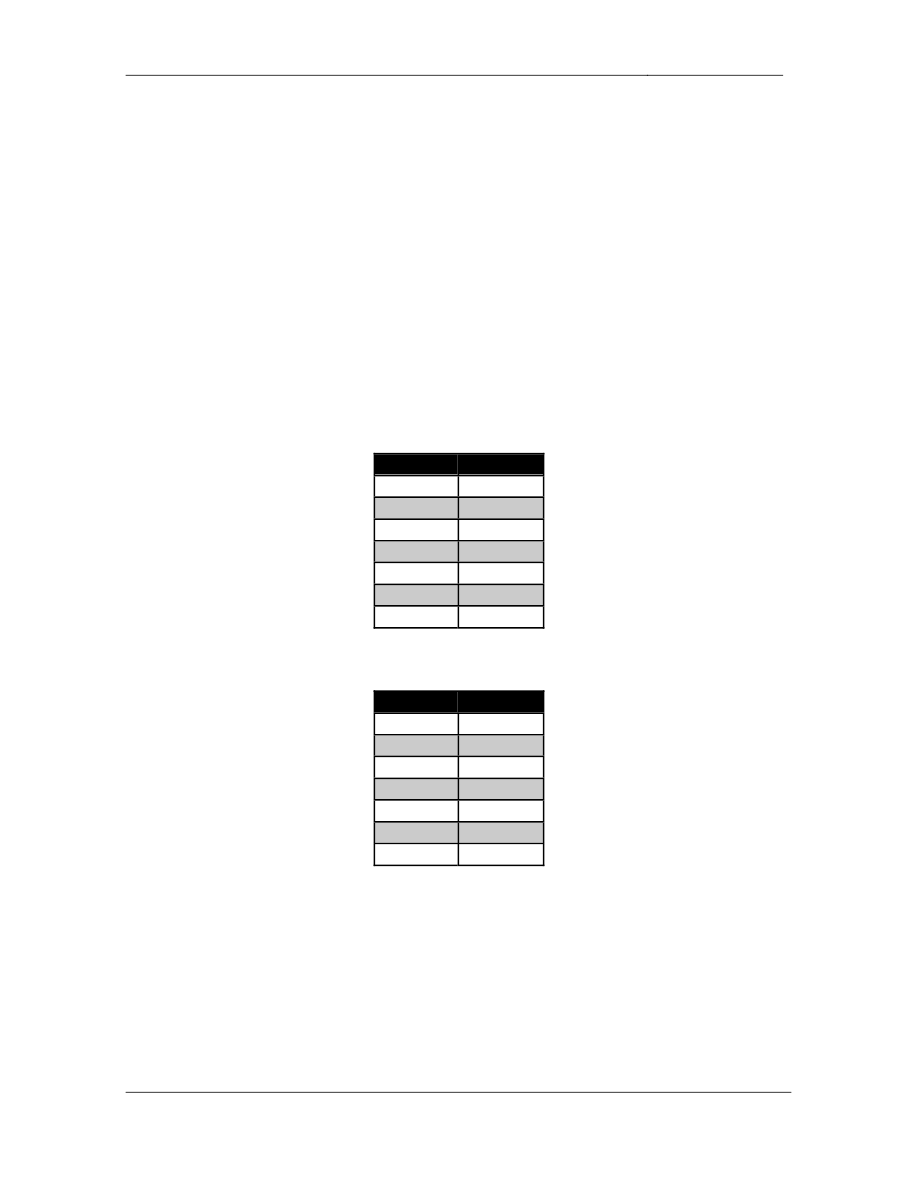
Point Values:
The point values for each section are as follows:
Section
Point Value
Bridging & Switching
14
Frame Relay
9
HDLC/PPP
3
Interior Gateway Routing
26
Exterior Gateway Routing
12
IP Multicast
5
IPv6
6
QoS
6
Security
6
System Management
8
IP Services
5
GOOD LUCK!

Accessed by arshadwasati@hotmail.com from 202.53.8.253 at 00:14:54 Mar 13,2007
CCIE Routing & Switching Lab Workbook Version 4.0
Lab 20
Copyright © 2007 Internetwork Expert
www.InternetworkExpert.com
- 367 -
1. Bridging & Switching
1.1. Trunking
• Configure
interfaces
Fa0/19
&
Fa0/21
on
SW1
and
SW3
as
ISL
trunk
links; these links should be bound together using LACP negotiation.
• Configure
interfaces
Fa0/19
-
21
on
SW2
as
802.1q
trunk
links.
• Configure
interface
Fa0/20
on
SW1
and
SW3
as
802.1q
trunk
links.
• Do
not
use
DTP
to
accomplish
this.
2 Points
1.2. VLAN Assignments
• Configure
the
VTP
domain
10
on
SW4.
• Configure
the
VTP
domain
789
on
SW1,
SW2,
and
SW3.
• SW2
and
SW3
should
learn
about
VLANs
created
on
SW1
but
should
not
be able to modify them.
• Create
and
configure
VLAN
assignments
per
the
diagram.
2 Points
1.3. Switch Management
• SW3
and
SW4
have
VLANs
89
and
107
configured
for
management
respectively.
• Configure
these
devices
so
that
SW3
sends
all
IPv4
traffic
to
SW2.
• SW4
should
send
all
IPv4
traffic
to
SW1.
1 Point

Accessed by arshadwasati@hotmail.com from 202.53.8.253 at 00:14:54 Mar 13,2007
CCIE Routing & Switching Lab Workbook Version 4.0
Lab 20
Copyright © 2007 Internetwork Expert
www.InternetworkExpert.com
- 368 -
1.4. Spanning-Tree Protocol
• Recently
engineers
in
your
network
operations
center
have
informed
you
that your switches are experiencing very high CPU utilization. After further
investigation you have determined that too many resources are being
dedicating to running individual instances of spanning-tree protocol on a
per VLAN basis. To help reduce CPU utilization run three instances of
spanning-tree protocol to service all VLANs assigned throughout your
network.
• Configure
your
network
so
that
VLANs
1,
5,
12,
and
107
are
mapped
to
the first instance of STP.
• VLANs
27,
34,
and
58
should
be
mapped
to
the
second
instance
of
STP.
• VLANs
46,
89,
and
363
should
be
mapped
to
the
last
instance
of
STP.
• The
name
of
this
spanning-tree
domain
should
be
IESTP,
and
use
a
revision number of 10.
3 Points
1.5. Spanning-Tree Protocol
• Configure
SW4
as
the
root
bridge
for
all
STP
instances.
• VLAN
27
traffic
from
SW1
to
SW2
should
be
sent
over
the
802.1q
trunk
link between SW1 and SW4; this configuration should be done on SW1.
3 Points
1.6. Spanning-Tree Protocol
• VLAN
363
traffic
from
SW2
to
SW3
should
use
port
Fa0/21.
• If
port
Fa0/21
is
down
it
should
use
port
Fa0/20.
• This
configuration
should
be
done
on
SW4.
3 Points

Accessed by arshadwasati@hotmail.com from 202.53.8.253 at 00:14:54 Mar 13,2007
CCIE Routing & Switching Lab Workbook Version 4.0
Lab 20
Copyright © 2007 Internetwork Expert
www.InternetworkExpert.com
- 369 -
2. Frame Relay
2.1. Full Mesh
• Using
only
physical
interfaces
configure
a
Frame
Relay
full
mesh
between
R3, R4, and R5.
• Use
only
the
DLCIs
specified
in
the
diagram.
• Do
not
use
Frame
Relay
Inverse-ARP.
3 Points
2.2. Bridging Over Frame Relay
• Recently
a
point-to-point
T1
circuit
has
been
provisioned
between
R1
and
R3 in order to migrate R1 off of the Frame Relay network. Additionally,
your provisioning department has put in an order for a new circuit to be
turned up between R2 and R3 over the Frame Relay cloud. In preparation
for this new setup in your network the design team has prematurely
changed your IP addressing scheme to fit the new point-to-point circuit
between R2 and R3. Unfortunately your change control policy dictates
that an IP address change on any non-host device in the network must go
through a long approval process. As a workaround in the meantime
configure R1 to provide transit services for this segment.
• Ensure
that
R1
will
route
out
the
T1
circuit
to
reach
this
network
once
IGP
connectivity has been established.
• Do
not
use
the
bridge irb command on R1 to accomplish this.
4 Points
2.3. Point-to-Point
• Configure
a
point-to-point
Frame
Relay
circuit
between
R6
and
BB1
per
the diagram.
• Use
only
the
main
interface
on
R6.
• Do
not
use
Frame
Relay
Inverse-ARP.
2 Points

Accessed by arshadwasati@hotmail.com from 202.53.8.253 at 00:14:54 Mar 13,2007
CCIE Routing & Switching Lab Workbook Version 4.0
Lab 20
Copyright © 2007 Internetwork Expert
www.InternetworkExpert.com
- 370 -
3. HDLC/PPP
3.1. EAP
• Configure
the
Serial
link
between
R1
and
R3
using
PPP
encapsulation.
• Your
company
has
decided
to
migrate
away
from
Challenge
Handshake
Authentication Protocol for all PPP links and implement the newer
Extensible Authentication Protocol. Management has requested for R1
and R3’s previous CHAP configuration be converted over to EAP.
• R1
and
R3’s
configuration
related
to
CHAP
is
as
follows:
R1:
username ROUTER3 password CISCO
!
interface Serial0/1
encapsulation ppp
ppp chap hostname ROUTER1
R3:
username ROUTER1 password CISCO
!
interface Serial0/1
encapsulation ppp
ppp authentication chap
ppp chap hostname ROUTER5
3 Points

Accessed by arshadwasati@hotmail.com from 202.53.8.253 at 00:14:54 Mar 13,2007
CCIE Routing & Switching Lab Workbook Version 4.0
Lab 20
Copyright © 2007 Internetwork Expert
www.InternetworkExpert.com
- 371 -
4. Interior Gateway Routing
4.1. OSPF
• Configure
OSPF
area
0
on
the
Ethernet
segment
between
R5
and
SW2.
• Since
there
can
not
possibly
be
any
other
neighbors
on
this
segment
R5
and SW2 should not elect a DR or BDR.
• Ensure
the
OSPF
dead
timers
are
set
to
40
seconds
on
this
segment
but
do not use the ip ospf dead-interval or ip ospf hello-interval commands
to accomplish this.
• Configure
OSPF
area
5
in
VLAN
5.
• Advertise
the
VLAN
89
the
Loopback0
interface
of
SW2
into
OSPF
area
0.
3 Points
4.2. OSPF
• Configure
OSPF
area
345
on
the
Frame
Relay
cloud
between
R3,
R4,
and
R5.
• Advertise
R3,
R4,
and
R5’s
Loopback
0
interfaces
into
OSPF
area
345.
• One
of
your
design
engineers
has
expressed
concerns
about
the
ability
of
OSPF to recover from a failure of a Frame Relay circuit between R3, R4,
and R5. This engineer has stated the following case:
o
If
R3
is
the
DR
for
the
OSPF
network
and
R4
loses
connectivity
to
the Frame Relay cloud through DLCI 413, it will no longer have
direct communication with R3. Therefore although it still has a
circuit up to R5, OSPF cannot properly communicate across the
network. This will also happen if R5 is the DR, and the circuit
between R3 & R5 or between R4 & R5 goes down.
• You
comfort
this
engineer
by
informing
him
that
you
know
a
simple
solution to this problem since you attended Internetwork Expert’s CCIE
Routing & Switching Advanced Technologies Class. Configure the OSPF
network to automatically recover from a failure of a single circuit across
the Frame Relay cloud.
3 Points

Accessed by arshadwasati@hotmail.com from 202.53.8.253 at 00:14:54 Mar 13,2007
CCIE Routing & Switching Lab Workbook Version 4.0
Lab 20
Copyright © 2007 Internetwork Expert
www.InternetworkExpert.com
- 372 -
4.3. OSPF
• Configure
OSPF
type
1
authentication
on
the
Frame
Relay
network.
• Use
the
password
of
CISCO
for
this
authentication.
• Do
not
use
the
area 345 authentication command to accomplish this
task.
2 Points
4.4. OSPF
• Configure
OSPF
type
2
authentication
for
all
adjacencies
in
area
0.
• Use
key
number
1
and
the
password
of
CISCO.
• Do
not
use
the
area 0 authentication message-digest command to
accomplish this task.
2 Points
4.5. OSPF
• One
of
the
design
engineers
has
recommend
that
when
R3
and
R4
bootup that they should not used as transit routers until they have had
time to fully synchronize their OSPF databases.
• Configure
R3
and
R4
to
advertise
all
OSPF
routes
with
a
maximum
metric
for the first 10 minutes after they have booted up.
2 Points
4.6. OSPF
• One
of
your
design
engineers
has
reported
to
you
that
the
both
the
CPU
utilization and the link utilization of routers connected to the Frame Relay
cloud is spiking roughly every 30 minutes. After explaining to this
engineer that this is OSPF’s ‘paranoid update’, and is normal behavior, he
has recommended to the rest of the network team that OSPF be replaced
with static routes. Since you have attended Internetwork Expert’s CCIE
Routing & Switching Advanced Technologies Class you once again inform
this engineer that there is a very simple solution to this problem.
• Configure
your
network
to
resolve
this
issue.
2 Points

Accessed by arshadwasati@hotmail.com from 202.53.8.253 at 00:14:54 Mar 13,2007
CCIE Routing & Switching Lab Workbook Version 4.0
Lab 20
Copyright © 2007 Internetwork Expert
www.InternetworkExpert.com
- 373 -
4.7. OSPF
• Configure
OSPF
area
345
on
the
Ethernet
link
between
R3
and
R4.
• Traffic
from
SW2
to
VLAN
34
should
use
the
Frame
Relay
circuit
between
R4 and R5.
• This
configuration
should
be
performed
on
R5.
• Do
not
use
the
cost or
bandwidth
keywords to accomplish this.
3 Points
4.8. EIGRP
• Configure
EIGRP
AS
100
on
R1,
R2,
R3,
and
SW1.
• Enable
EIGRP
on
the
PPP
link
between
R1
and
R3.
• Enable
EIGRP
on
the
Frame
Relay
network
between
R2
and
R3.
• Enable
EIGRP
on
the
Ethernet
segment
between
R2
and
SW1.
• Enable
EIGRP
on
VLAN
107
of
SW1.
• Advertise
the
Loopback
0
interfaces
of
R1,
R2,
and
SW1
with
EIGRP.
• After
a
recent
issue
with
EIGRP
routes
from
your
company’s
CCNA
practice lab leaking into the production network, you have decided to
authenticate all EIGRP adjacencies.
• Secure
the
EIGRP
neighbor
relationships
between
R2,
R3,
and
SW1
with
the password CISCO.
3 Points
4.9. RIP
• Configure
RIP
on
R3,
R4,
and
R6.
• Enable
RIP
on
VLANs
46
and
363.
• Advertise
the
Frame
Relay
link
between
R6
and
BB1
into
RIP.
• Your
RIP
enabled
routers
should
not
install
any
RIP
routes
from
BB1
and
BB3.
• BB1
and
BB3
should
not
install
any
RIP
routes
from
your
routers.
• Do
not
use
the
distribute-list keyword to accomplish this.
3 Points
Accessed by arshadwasati@hotmail.com from 202.53.8.253 at 00:14:54 Mar 13,2007
CCIE Routing & Switching Lab Workbook Version 4.0
Lab 20
Copyright © 2007 Internetwork Expert
www.InternetworkExpert.com
- 374 -
4.10. IGP Redistribution
• Redistribute
between
EIGRP,
RIP,
and
OSPF
on
R3.
• Redistribute
between
RIP
and
OSPF
on
R4.
• R6
should
use
R3
to
reach
routes
inside
the
EIGRP
domain,
and
use
R4
to reach routes inside the OSFP domain.
3 Points
5. Exterior Gateway Routing
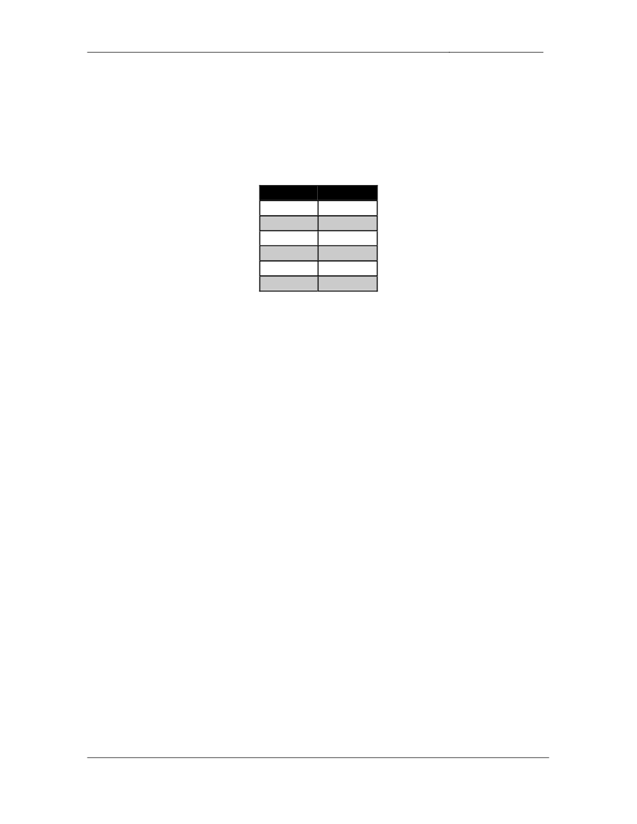
5.1. BGP Peering
• Configure
BGP
on
the
following
devices
with
the
following
AS
numbers:
Device
BGP AS
R1
200
R3
300
R4
300
R6
100
BB1
54
BB2
254
BB3
54
• Configure
the
BGP
peering
sessions
as
follows:
Device 1
Device 2
R1
R3
R1
BB2
R3
R4
R3
R6
R4
R6
R6
BB1
R6
BB3
• R1
and
R3
should
peer
using
their
Loopback
0
interfaces.
• Secure
the
BGP
session
between
R1
and
BB2
using
the
password
of
CISCO.
3 Points

Accessed by arshadwasati@hotmail.com from 202.53.8.253 at 00:14:54 Mar 13,2007
CCIE Routing & Switching Lab Workbook Version 4.0
Lab 20
Copyright © 2007 Internetwork Expert
www.InternetworkExpert.com
- 375 -
5.2. BGP Bestpath Selection
• Even
though
AS
300
is
directly
connected
to
AS
54,
the
fastest
path
to
reach it is out through AS 100’s OC3 link. In order to follow this
forwarding path, configure your network so that all traffic destined for
prefixes learned from AS 54 traverses the Ethernet segment between R4
and R6.
• In
the
case
that
the
Ethernet
segment
between
R4
and
R6
is
unavailable,
AS 300 should reroute to R6 by using Ethernet segment between R3 and
R6.
• Do
not
alter
the
weight,
local-preference,
or
next-hop
values
of
these
prefixes to accomplish this.
3 Points
5.3. BGP Filtering
• After
failed
negotiations
between
management
groups
AS
200
has
now
refused to provide transport for AS 300 to reach AS 254.
• Configure
AS
200
to
reflect
this
policy,
but
do
not
use
any
outbound
filtering techniques or the community no-export.
• Ensure
that
R1
still
has
reachability
to
AS
254.
3 Points
5.4. BGP Redistribution
• To
ensure
that
non
BGP
speaking
devices
have
full
connectivity
your
design engineers have recommended that R3 and R4 redistribute their
BGP learned prefixes into IGP. You have voiced your concerns about
redistributing the full BGP table into IGP and have suggested instead that
R3 & R4 inject a default route. After further negotiations with the design
team, you have agreed to redistribute BGP into IGP, but only those
prefixes which are less than four autonomous systems away.
• Configure
R3
and
R4
to
reflect
this
policy.
• To
help
safe
guard
this
redistribution
policy,
configure
R3
and
R4
to
reset
any BGP session that is sending more than 1000 prefixes.
3 Points
Accessed by arshadwasati@hotmail.com from 202.53.8.253 at 00:14:54 Mar 13,2007
CCIE Routing & Switching Lab Workbook Version 4.0
Lab 20
Copyright © 2007 Internetwork Expert
www.InternetworkExpert.com
- 376 -
6. IP Multicast
6.1. PIM
• Configure
IP
Multicast
routing
on
R1,
R3,
and
R4.
• Configure
PIM
sparse
mode
on
the
following
interfaces:
Device
Interface
R1
Fa0/0
R1
S0/1
R3
E0/0
R3
S1/2
R4
E0/0
R4
E0/1
• Configure
R4
to
announce
its
Loopback
0
interface
as
the
RP
for
all
multicast groups.
• Do
not
use
the
ip pim autorp listener command to accomplish this.
3 Points
6.2. Multicast Testing
• Configure
R1’s
Ethernet
interface
to
join
multicast
group
231.31.31.31.
• R3
and
R4
should
be
able
to
successfully
ping
the
multicast
group
address joined by R1.
2 Points

Accessed by arshadwasati@hotmail.com from 202.53.8.253 at 00:14:54 Mar 13,2007
CCIE Routing & Switching Lab Workbook Version 4.0
Lab 20
Copyright © 2007 Internetwork Expert
www.InternetworkExpert.com
- 377 -
7. IPv6
7.1. IPv6 Addressing
• Enable
IPv6
processing
on
R2
and
R5.
• Configure
IPv6
on
VLAN
27
using
the
network
2002:8EXX:3502:0027::/64
where XX is your rack number.
• Configure
IPv6
on
VLAN
5
using
the
network
2002:8EXX:0505:0005::/64
where XX is your rack number.
3 Points
7.2. IPv6 Tunneling
• Hosts
on
VLANs
5
and
27
want
to
talk
to
each
other
via
IPv6.
Additionally
your design team has notified you that hosts on these segments will soon
be communicating with other IPv6 enabled hosts outside your network as
well. However, your current demand for IPv6 does not dictate that the
protocol should be enabled on every device throughout your transit
network.
• Configure
your
network
in
such
a
way
that
hosts
on
VLANs
5
and
27
can
communicate with each other, and so that they can communicate with an
arbitrary number of IPv6 enabled segments that are reachable via the
IPv4 network in the future.
3 Points

Accessed by arshadwasati@hotmail.com from 202.53.8.253 at 00:14:54 Mar 13,2007
CCIE Routing & Switching Lab Workbook Version 4.0
Lab 20
Copyright © 2007 Internetwork Expert
www.InternetworkExpert.com
- 378 -
8. QoS
8.1. IP TOS
• Prior
to
implementing
a
new
QoS
policy,
you
have
been
monitoring
your
network for any packets that have the TOS byte set. You have noticed
that TCP packets sourced by the routers have the first two most significant
bits of the TOS byte set in the IP header. At first you thought these were
just BGP packets and were not really concerned, but after looking closer
you noticed that these were actually telnet packets. Since marking telnet
packets with the TOS of 0xC0 will conflict with your new QoS policy, you
have decided to have all routers set the TOS for telnet packets to 0x0.
Configure your network to reflect this policy.
2 Points
8.2. WRED
• Users
on
VLAN
27
have
been
complaining
about
slow
access
to
the
rest
of the network. After further investigation you have determined that the
output queue of R2’s Serial interface is full, and traffic attempting to enter
the queue is getting dropped.
• To
help
alleviate
congestion
configure
R2
to
selectively
drop
traffic
on
the
Serial interface before the output queue becomes full.
• Traffic
with
a
higher
DSCP
value
should
be
less
likely
to
be
dropped
than
traffic with a lower value.
2 Points
8.3. Marking
• After
implementing
the
new
queueing
strategy
on
R2
you
have
noticed
slow response time to your web server located on VLAN 27. Apparently
the web server service is not marking its TCP traffic with a DSCP value,
and is therefore less preferred over other traffic.
• To
decrease
response
time
to
the
server
configure
R2
so
that
traffic
from
this server is least likely to be dropped as it is sent out to the Frame Relay
cloud.
• The
server’s
address
is
142.X.27.100.
2 Points

Accessed by arshadwasati@hotmail.com from 202.53.8.253 at 00:14:54 Mar 13,2007
CCIE Routing & Switching Lab Workbook Version 4.0
Lab 20
Copyright © 2007 Internetwork Expert
www.InternetworkExpert.com
- 379 -
9. Security
9.1. Traffic Filtering
• Recent
traffic
monitoring
of
your
network
has
indicated
that
various
hosts
from behind BB1 are performing port scans on your network. Configure
R6 so that these hosts are denied entry into your network. The IP
addresses of these hosts are as follows:
o
51.3.0.1
o
51.5.0.1
o
51.7.0.1
o
51.3.0.9
o
51.5.0.9
o
51.7.0.9
• Use
the
minimum
amount
of
lines
necessary
to
complete
this
task.
• Do
not
deny
traffic
from
any
other
hosts.
3 Points
9.2. Reflexive Access-Lists
• The
majority
of
these
port
scans
were
destined
to
hosts
on
VLAN
27.
In
order to protect hosts on this segment in the future your security team has
asked you to implement a reflexive access-list on R2.
• Configure
this
access-list
on
R2
in
such
a
way
that
hosts
using
TCP
and
UDP based applications on VLAN 27 can access the rest of the network.
• Ensure
that
hosts
outside
VLAN
27
can
access
your
web
server,
and
that
you can ping and telnet to SW1’s SVI for management purposes.
3 Points

Accessed by arshadwasati@hotmail.com from 202.53.8.253 at 00:14:54 Mar 13,2007
CCIE Routing & Switching Lab Workbook Version 4.0
Lab 20
Copyright © 2007 Internetwork Expert
www.InternetworkExpert.com
- 380 -
10. System Management
10.1. SNMP
• Two
new
network
management
servers
have
been
installed
to
manage
R5. Configure R5 for the following SNMP parameters:
o
Contact:
CCIE
Lab
R5
o
Location:
San
Jose,
CA
US
• The
first
network
management
server’s
IP
address
is
142.X.5.100
and
the
second network management server’s IP address is 142.X.58.100.
• The
network
management
servers
are
expecting
the
RO
community
string
to be CISCORO and the RW community to be CISCORW.
• SNMP
traps
should
be
sent
with
the
community
CISCOTRAP.
• Log
any
other
device
that
tries
to
poll
R5
via
SNMP.
• To
maintain
consistency
in
monitoring
R5’s
interfaces
ensure
that
the
ifIndex values do not change across reboots.
3 Points
10.2. SNMP
• After
the
installation
of
the
two
new
network
management
servers,
you
have noticed high CPU utilization related to the SNMP process on R5.
After further investigation it seems that the NOC is polling for R5’s routing
table and ARP table via SNMP.
• Disable
the
ability
of
R5
to
be
polled
via
SNMP
for
its
routing
table
(ip.21)
and ARP table (ip.22).
• R5
should
continue
support
for
all
other
MIBs
(iso).
3 Points

Accessed by arshadwasati@hotmail.com from 202.53.8.253 at 00:14:54 Mar 13,2007
CCIE Routing & Switching Lab Workbook Version 4.0
Lab 20
Copyright © 2007 Internetwork Expert
www.InternetworkExpert.com
- 381 -
10.3. IOS Image Management
• During
a
maintenance
window
the
previous
night
you
noticed
that
R3
had
to be reloaded three times to finally get it to recognize its flash memory.
This in turn caused R3 to try and boot a default IOS image via TFTP.
Since most of your companies networking infrastructure was purchased
off eBay you are not able to RMA the flash module with Cisco. Until you
can buy a new flash memory module off eBay configure R3 to boot a
default IOS image from R4 in the event that it can not locate its own image
in flash.
• Do
not
apply
any
configuration
on
R3
to
accomplish
this
task.
2 Points
11. IP Services
11.1. Local Authorization
• You
have
opened
a
case
with
TAC
to
help
troubleshoot
an
issue
relating
to R4 crashing. TAC has requested access to R4 in order to help
troubleshoot the problem. Allow TAC to telnet into R4 using username
TAC and password CISCO.
• Since
your
corporate
policy
denies
non-company
personnel
access
to
your networking infrastructure, you have decided to only give TAC limited
access. When the TAC engineer telnets into R4 they should be placed
into privilege level 0 and given access to the following commands:
o
show
version
o
show
processes
cpu
o
show
stack
o
show
memory
3 Points

Accessed by arshadwasati@hotmail.com from 202.53.8.253 at 00:14:54 Mar 13,2007
CCIE Routing & Switching Lab Workbook Version 4.0
Lab 20
Copyright © 2007 Internetwork Expert
www.InternetworkExpert.com
- 382 -
11.2. Telnet Filtering
• The
TAC
engineers
will
be
telneting
from
the
following
IP
addresses:
o
45.194.169.115
o
61.202.173.243
o
41.234.41.250
• Without
regards
to
overlapping
additional
IP
addresses
use
the
most
efficient one line access-list to permit these three IP address to telnet into
R4.
2 Points
Wyszukiwarka
Podobne podstrony:
IE RS lab 18 overview
IE RS lab 20 diagram
IE RS Lab 16 overview
IE RS lab 17 overview
IE RS lab 10 overview
IE RS lab 11 overview
IE RS lab 13 overview
IE RS lab 15 overview
IE RS lab 19 overview
IE RS lab 9 overview
IE RS lab 11 solutions
IE RS lab 10 solutions
IE RS lab 12 solutions
IE RS lab 18 Diagram
IE RS lab 9 solutions
IE RS lab 11 diagram
IE RS lab 19 diagram
IE RS lab 8 diagram
IE RS lab 13 solutions
więcej podobnych podstron