
CCIE Routing & Switching Lab Workbook Version 4.0
Lab 19
Copyright © 2007 Internetwork Expert
www.InternetworkExpert.com
- 349 -
IEWB-RS Lab 19
Difficulty Rating (10 highest): 10
Lab Overview:
The following scenario is a practice lab exam designed to test your skills at
configuring Cisco networking devices. Specifically, this scenario is designed to
assist you in your preparation for Cisco Systems’ CCIE Routing and Switching
Lab exam. However, remember that in addition to being designed as a
simulation of the actual CCIE lab exam, this practice lab should be used as a
learning tool. Instead of rushing through the lab in order to complete all the
configuration steps, take the time to research the networking technology in
question and gain a deeper understanding of the principles behind its operation.
Lab Instructions:
Prior to starting, ensure that the initial configuration scripts for this lab have been
applied. For a current copy of these scripts, see the Internetwork Expert
members site at
http://members.internetworkexpert.com
Refer to the attached diagrams for interface and protocol assignments. Any
reference to X in an IP address refers to your rack number, while any reference
to Y in an IP address refers to your router number.
Upon completion, all devices should have full IP reachability to all networks in the
routing domain, including any networks generated by the backbone routers
unless explicitly specified.
Lab Do’s and Don’ts:
• Do
not
change
or
add
any
IP
addresses
from
the
initial
configuration
unless otherwise specified
• Do
not
change
any
interface
encapsulations
unless
otherwise
specified
• Do
not
change
the
console,
AUX,
and
VTY
passwords
or
access
methods
unless otherwise specified
• Do
not
use
any
static
routes,
default
routes,
default
networks,
or
policy
routing unless otherwise specified
• Save
your
configurations
often
CCIE Routing & Switching Lab Workbook Version 4.0
Lab 19
Copyright © 2007 Internetwork Expert
www.InternetworkExpert.com
- 350 -
Grading:
This practice lab consists of various sections totaling 100 points. A score of 80
points is required to achieve a passing score. A section must work 100% with the
requirements given in order to be awarded the points for that section. No partial
credit is awarded. If a section has multiple possible solutions, choose the solution
that best meets the requirements.
Grading for this practice lab is available when configured on Internetwork
Expert’s racks, or the racks of Internetwork Expert’s preferred vendors. See
Internetwork Expert’s homepage at
http://www.internetworkexpert.com
for more
information.
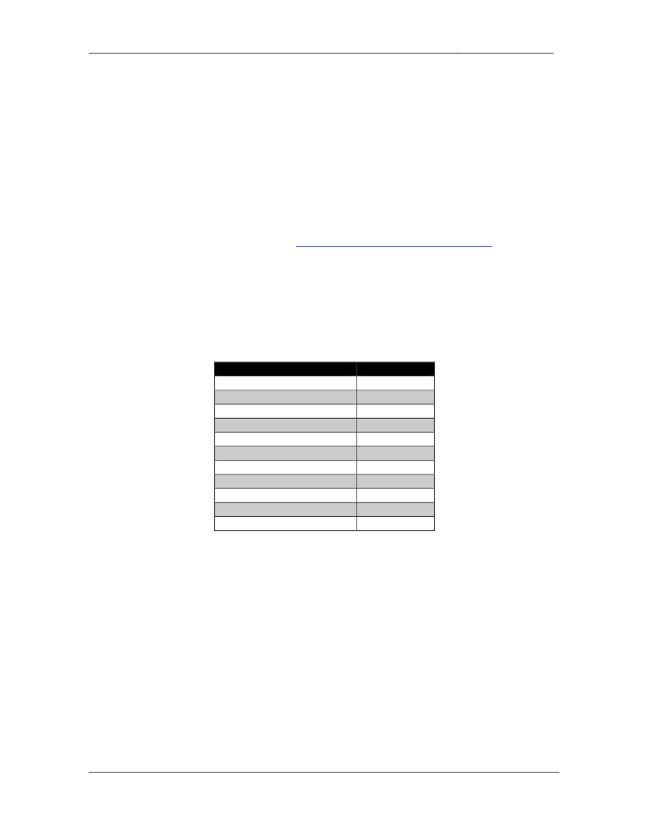
Point Values:
The point values for each section are as follows:
Section
Point Value
Bridging & Switching
12
Frame Relay
6
HDLC/PPP
3
Interior Gateway Routing
16
Exterior Gateway Routing
21
IP Multicast
9
IPv6
6
QoS
6
Security
5
System Management
6
IP Services
10
GOOD LUCK!
CCIE Routing & Switching Lab Workbook Version 4.0
Lab 19
Copyright © 2007 Internetwork Expert
www.InternetworkExpert.com
- 351 -
1. Bridging & Switching
1.1. VLAN Assignments
• Configure
the
VTP
domain
CCIE
between
SW1,
SW2,
SW3,
and
SW4.
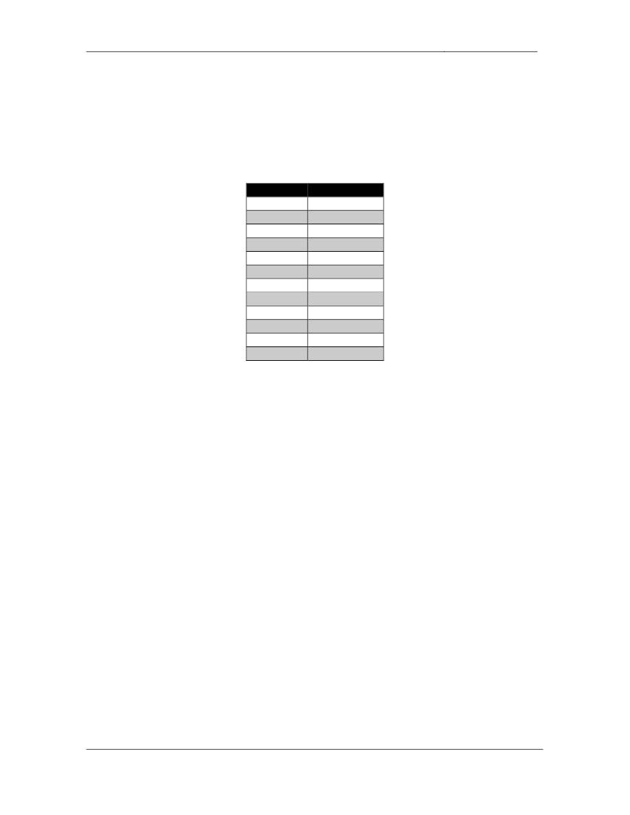
• Create
the
following
VLANs:
VLAN
Name
127
A
4
B
5
C
7
SW1_A
8
D
10
RSPAN
32
BB2
33
BB3
44
F
77
SW1_B
88
G
568
I
• Assign
the
above
VLANs
per
the
diagram
using
the
command
macro
apply ACCESSPORT $VLAN X, where X is the VLAN number to
configure the VLAN assignments on all interfaces; This command should
also set the administrative mode of the interface to static access and
disable the spanning-tree forwarding delay.
3 Points
1.2. Trunking
• Configure
ISL
trunk
links
between
SW1
&
SW4,
SW2
&
SW4,
and
SW3
&
SW4.
• Use
the
lowest
numbered
interfaces
to
accomplish
this.
• SW4
should
initiate
negotiation
of
these
links
and
SW1,
SW2,
and
SW3
should respond.
3 Points

CCIE Routing & Switching Lab Workbook Version 4.0
Lab 19
Copyright © 2007 Internetwork Expert
www.InternetworkExpert.com
- 352 -
1.3. Channeling
• Configure
EtherChannel
links
between
SW1
&
SW2
and
SW2
&
SW3
using all available links.
• These
links
should
use
a
4-byte
trunking
encapsulation.
• Traffic
leaving
these
links
on
SW2
should
be
load
balanced
based
on
the
destination IPv4 address.
3 Points
1.4. RSPAN
• Users
in
VLAN
127
have
been
reporting
slow
network
response
time,
however your administrators have not been able to track down the
problem. In order to collect more information your NOC engineers have
requested that you redirect all traffic received in VLAN 127 to a host
running Ethereal in your network.
• This
host
is
attached
to
port
Fa0/10
of
SW3.
• Use
VLAN
10
for
transporting
this
traffic.
3 Points
2. Frame Relay
2.1. Hub-and-Spoke
• Using
only
physical
interfaces
configure
a
Frame
Relay
hub-and-spoke
network between R1, R2, and R3 with R3 as the hub.
• Traffic
from
R1
destined
for
R2
should
transit
R3,
and
vice
versa.
• Use
only
the
DLCIs
specified
in
the
diagram.
• Do
not
use
any
dynamic
layer
3
to layer
2
mappings
over
these
Frame
Relay connections.
• Do
not
send
any
redundant
broadcast
traffic
from
the
spokes
to
the
hub.
2 Points

CCIE Routing & Switching Lab Workbook Version 4.0
Lab 19
Copyright © 2007 Internetwork Expert
www.InternetworkExpert.com
- 353 -
2.2. Hub-and-Spoke
• Using
only
physical
interfaces
configure
a
Frame
Relay
hub-and-spoke
network between R3, R4, and R5 with R5 as the hub.
• Use
only
the
DLCIs
specified
in
the
diagram.
• Do
not
use
any
dynamic
layer
3
to layer
2
mappings
over
these
Frame
Relay connections.
• Do
not
configure
static
layer
3
to
layer
2
mappings
between
the
spokes.
2 Points
2.3. Point-to-Point
• Configure
the
Frame
Relay
circuit
between
R6
and
BB1
per
the
diagram.
• Do
not
use
dynamic
protocol
mappings
over
this
link.
2 Points
3. HDLC/PPP
3.1. PPP
• Configure
PPP
encapsulation
on
the
Serial
link
between
R4
and
R5.
• R4
and
R5
should
authenticate
each
other
across
this
link.
Both
R4
and
R5 should send their hostname along with the hash value that represents
that password CISCO.
• Configure
R4
so
that
it
will
not
respond
to
a
CHAP
authentication
request
before R5 has been successfully authenticated.
3 Points

CCIE Routing & Switching Lab Workbook Version 4.0
Lab 19
Copyright © 2007 Internetwork Expert
www.InternetworkExpert.com
- 354 -
4. Interior Gateway Routing
4.1. OSPF
• Configure
OSPF
area
0
on
the
Frame
Relay
connection
between
R3,
R4,
and R5.
• Configure
your
network
so
that
R3
and
R4
gain
reachability
to
each
other
over the Frame Relay network through layer 3 routing instead of static
layer 3 to layer 2 resolution.
• Advertise
VLAN
44
into
OSPF
area
0.
3 Points
4.2. OSPF
• Configure
OSPF
area
568
on
VLAN
568
between
R5,
R6,
and
SW2.
• R5
should
be
elected
for
as
the
DR
for
this
segment.
• In
the
case
that
R5
goes
down
R6
should
assume
the
role
of
the
DR.
3 Points
4.3. OSPF
• Recently
a
Windows
host
on
VLAN
568
running
OSPF
injected
false
information into your routing domain and caused a traffic black hole. In
response to this you have put a new policy in place which states that all
adjacencies in OSPF area 568 must be authenticated with a secure hash
value.
• In
addition
to
this
configure
your
network
so
that
unauthorized
devices
cannot intercept OSPF hello packets as they are transiting VLAN 568.
3 Points

CCIE Routing & Switching Lab Workbook Version 4.0
Lab 19
Copyright © 2007 Internetwork Expert
www.InternetworkExpert.com
- 355 -
4.4. OSPF
• Configure
OSPF
area
0
on
the
PPP
link
between
R4
and
R5.
• The
PPP
link
between
R4
and
R5
will
be
a
backup
of
the
Frame
Relay
circuit between them. Configure the network in such a way that this link is
only used if R4 loses its connection to the Frame Relay cloud.
3 Points
4.5. OSPF
• Administrators
of
your
network
have
been
noticing
inconsistencies
with
the
OSPF database when the PPP link is being used. After further
investigation they have determined that congestion on this link has been
preventing LSAs from correctly propagating. In order to deal with this
problem your design team has suggested that you increase the estimated
time required to send a link-state update packet on this interface to 5
seconds.
• Additionally
they
have
suggested
that
if
an
acknowledgement
for
an
LSA
sent across this interface is not received within 10 seconds, the LSA
should be retransmitted.
• Configure
the
network
to
reflect
this
recommendation.
2 Points
4.6. OSPF
• Advertise
the
Loopback
0
interfaces
of
R3,
R4,
R5,
R6
and
SW2
into
OSPF.
• These
networks
should
appear
in
the
routing
table
of
all
OSPF
speaking
devices with a subnet mask of /24.
• Do
not
use
the
ip ospf network command to accomplish this.
2 Points
CCIE Routing & Switching Lab Workbook Version 4.0
Lab 19
Copyright © 2007 Internetwork Expert
www.InternetworkExpert.com
- 356 -
5. Exterior Gateway Routing
5.1. BGP Peering
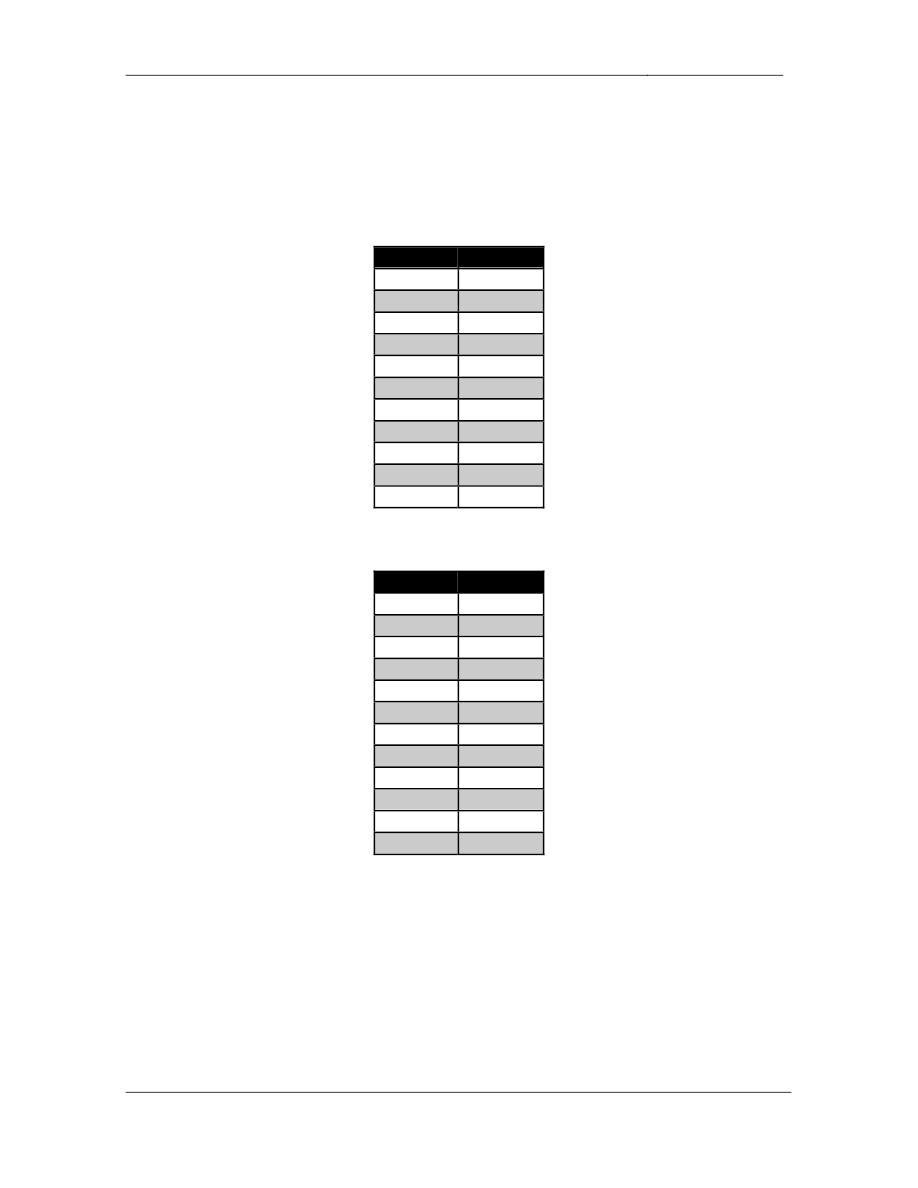
• Configure
BGP
on
the
following
devices
with
the
following
AS
numbers:
Device
BGP AS
R1
300
R2
300
R3
200
R4
100
R5
100
R6
100
SW1
300
SW2
100
BB1
54
BB2
254
BB3
54
• Configure
the
BGP
peering
sessions
as
follows:
Device 1
Device 2
R6
BB1
R6
R5
R5
SW2
R5
R4
R5
R3
R3
BB2
R3
BB3
R3
R1
R3
R2
R1
R2
R1
SW1
R2
SW1

CCIE Routing & Switching Lab Workbook Version 4.0
Lab 19
Copyright © 2007 Internetwork Expert
www.InternetworkExpert.com
- 357 -
• Ensure
that
the
BGP
peering
session
between
R4
&
R5
remains
up
even
if R4 loses its connection to the Frame Relay cloud.
• Due
to
previous
problems
with
false
information
being
injected
into
the
BGP domain, AS 254 now requires all BGP peering relationships to be
authenticated with a secure hash value of the password CISCO.
• Configure
R3
to
reflect
this
policy.
• Recently
AS
200
acquired
R3
from
AS
100.
AS
100’s
previous
customer,
AS 54, has yet to update its configuration. Configure your network so that
R3 still appears to be in AS 100 from the perspective of BB3. Ensure that
you configure this peering relationship in such a way that AS 100 can still
use AS 200 as transit to get to AS 54.
4 Points
5.2. BGP Advertisements
• Advertise
VLANs
4,
5,
7,
8,
77,
88,
and
127
into
the
BGP
domain.
• Advertise
the
Frame
Relay
network
between
R1,
R2,
and
R3
into
BGP.
• Advertise
the
Loopback
0
interfaces
of
R1,
R2,
and
SW1
into
BGP.
• All
of
these
prefixes
should
have
an
origin
code
of
incomplete after being
advertised into BGP.
2 Points
5.3. BGP Filtering
• Since
AS
300’s
only
upstream
peer
is
AS
200,
it
does
not
need
specific
forwarding information about the rest of the BGP domain.
• Configure
your
network
so
that
AS
300
sees
only
a
default
route
from
R3,
as well as prefixes originated by AS 200’s directly connected customers.
3 Points

CCIE Routing & Switching Lab Workbook Version 4.0
Lab 19
Copyright © 2007 Internetwork Expert
www.InternetworkExpert.com
- 358 -
5.4. BGP Bestpath Selection
• Configure
AS
300
so
that
all
traffic
destined
for
VLAN
7
enters
the
Frame
Relay circuit between R1 and R3 while all traffic destined for VLAN 77
enters the Frame Relay circuit between R2 and R3.
• R3
should
load
balance
traffic
destined
for
VLAN
127
amongst
both
Frame Relay connections to AS 300.
3 Points
5.5. BGP Aggregation
• In
order
to
help
reduce
the
size
of
the
global
BGP
table
AS
200
has
decided to aggregate all networks learned from their customers.
• Configure
R3
to
originate
an
aggregate
prefix
that
represents
all
of
the
VLANs that have been originated into BGP.
• R3
should
not
advertise
any
subnets
which
make
up
this
aggregate
to
any
neighbor.
3 Points
5.6. BGP Aggregation
• Shortly
after
configuring
this
aggregation
policy
engineers
in
AS
200
began to notice odd patterns with traffic destined to this aggregate block.
Apparently the aggregate prefix originated by AS 200 is getting passed on
from AS 100 to AS 54. Then AS 54 is sending traffic to AS 100 for which
the longest match is the aggregate block. This in turn causes AS 100 to
forward the traffic back to AS 200 where it is eventually dropped. In
response to this your engineers have decided to send AS 100 only the
subnets instead of the aggregate, but still send only the aggregate to all
other peers.
• Configure
AS
200
to
reflect
this
policy.
3 Points

CCIE Routing & Switching Lab Workbook Version 4.0
Lab 19
Copyright © 2007 Internetwork Expert
www.InternetworkExpert.com
- 359 -
5.7. BGP Aggregation
• While
this
seemed
like
a
good
idea
on
the
surface
a
new
problem
has
now
arisen. Since AS 100 is peering with AS 54 it is learning the aggregate
block which is advertised from AS 200 to AS 54. Since the aggregate
appears to have originated in AS 200, AS 100 is accepting it as a valid
prefix. Now AS 100 is sending traffic that it does not have a longer match
for to AS 54, which in turn forwards the traffic back to AS 200 where it is
eventually dropped. This behavior has left the engineers on your ISP
team scratching their heads. Finally your network team has devised the
following solution for you to implement:
o
When
originating
the
aggregate
address
AS
200
should
include
an
ordered set of the autonomous systems from which the subnets
were originated. Therefore AS 100 cannot accept the prefix from
AS 54 due to its own AS being in the path.
o
Furthermore
since
AS
300
will
not
accept
a
prefix
that
has
its
own
AS in the path, the aggregate should only include AS 100 in the
ordered set.
• Configure
R3
to
reflect
this
policy.
3 Points
CCIE Routing & Switching Lab Workbook Version 4.0
Lab 19
Copyright © 2007 Internetwork Expert
www.InternetworkExpert.com
- 360 -
6. Multicast
6.1. PIM
• Configure
IP
Multicast
routing
on
R1,
R2,
R3,
R4,
R5,
and
SW1.
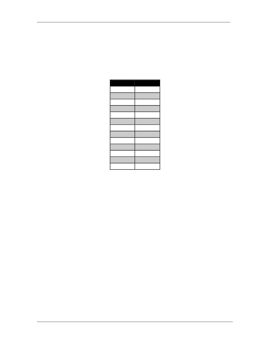
• Configure
PIM
sparse
mode
on
the
following
interfaces:
Device
Interface
R1
Fa0/0
R1
S0/0
R2
Fa0/0
R2
S0/0
R3
S1/0
R3
S1/1
R4
E0/1
R4
S0/0
R5
E0/0
R5
S0/0
SW1
VL7
SW1
VL77
SW1
VL127
3 Points
6.2. RP Assignment
• Configure
SW1
to
announce
itself
as
a
Rendezvous
Point
for
the
PIM
domain.
• R3
should
be
responsible
for
group
to
RP
mappings.
3 Points
6.3. Multicast Testing
• A
multicast
server
located
in
VLAN
7
will
be
sending
feeds
to
users
in
VLANs 4 and 5. In order to ensure that this configuration will be functional
configure the network so that R4 and R5 respond to ICMP echo requests
sent to the group address 224.1.1.1 sent from VLAN 7.
• Do
not
use
tunneling
or
static
RP
assignments
to
accomplish
this.
3 Points

CCIE Routing & Switching Lab Workbook Version 4.0
Lab 19
Copyright © 2007 Internetwork Expert
www.InternetworkExpert.com
- 361 -
7. IPv6
7.1. IPv6 Addressing
• Configure
IPv6
on
R3’s
connection
to
VLAN
32
using
the
address
2001:192:10:X::/64.
• Configure
IPv6
on
the
Frame
Relay
circuit
between
R1,
R2,
and
R3
using
the network 2001:149:X:123::/64.
• Configure
IPv6
on
VLAN
127
between
R1
and
R2
using
the
network
2001:149:X:127::/64.
• Hosts
in
VLAN
127
should
use
R1
as
their
default
gateway.
3 Points
7.2. RIPng
• Configure
RIPng
on
all
segments
running
IPv6.
• Hosts
on
VLAN
127
should
prefer
to
use
the
Frame
Relay
PVC
between
R1 and R3 to reach prefixes learned from BB2.
• If
this
circuit
is
down
they
should
be
rerouted
to
R2’s
PVC
to
R3.
3 Points
8. QoS
8.1. Frame Relay Traffic Shaping
• Recently
you
have
been
noticing
drops
on
R3’s
Frame
Relay
PVC
which
connects to R2. Apparently your level 1 administrators failed to take into
account the difference in port speeds between R2’s 64Kbps interface and
R3’s T1 interface when configuring this circuit.
• In
order
to
help
alleviate
congestion
configure
Frame
Relay
Traffic
Shaping on R3 to reduce its average output rate on the circuit.
• R3
should
attempt
to
average
on
output
rate
of
64Kbps
on
this
circuit.
• In
the
case
that
R3
has
accumulated
credit
it
should
be
allowed
to
send
a
maximum of 12Kb of data in a single interval.
• Use
the
default
Tc
for
this
circuit.
3 Points

CCIE Routing & Switching Lab Workbook Version 4.0
Lab 19
Copyright © 2007 Internetwork Expert
www.InternetworkExpert.com
- 362 -
8.2. Frame Relay Traffic Shaping
• Further
monitoring
of
R3’s
Frame
Relay
circuit
to
R2
has
indicated
that
the
issue has been resolved. However now you have been getting complaints
from users on VLAN 127 about horrible network response time. The
complaints seem to have been coming from users on VLAN 127 that are
using R1 as their default gateway. After speaking with the rest of your
network team, it seems that no other recent configuration changes have
been made regarding this circuit.
• Configure
your
network
to
resolve
this
problem.
3 Points
9. Security
9.1. Traffic Policing
• Recent
traffic
monitoring
in
your
network
has
indicated
a
suspiciously
high
amount of ICMP packets being received on R6’s Frame Relay circuit to
BB1. After further investigation it appears as though your network is
undergoing a DoS attack.
• In
order
to
reduce
the
impact
of
this
attack
on
the
rest
of
your
internal
network configure R6 to police all ICMP traffic received from BB1 to 8Kbps
with the minimum possible burst.
• Do
not
use
an
access-list
to
accomplish
this.
3 Points
9.2. Address Spoofing
• After
reviewing
your
log
files
you
have
determined
that
the
DoS
attack
came from hosts with spoofed private addresses.
• To
help
prevent
this
type
of
attack
in
the
future
configure
your
network
so
that traffic will not be accepted from BB1 if it has been originated from
these hosts.
2 Points

CCIE Routing & Switching Lab Workbook Version 4.0
Lab 19
Copyright © 2007 Internetwork Expert
www.InternetworkExpert.com
- 363 -
10. System Management
10.1. IOS Image Management
• Recently
a
security
auditor
downloaded
all
of
your
devices’
configuration
files via TFTP. Subsequently management has decided that TFTP is too
insecure of a method to backup your devices’ configurations. You have
been tasked with setting up R3 to test out the new FTP server that will be
used to backup devices’ configurations.
• The
FTP
server's
IP
address
is
149.X.5.100.
• The
username
for
R3
to
use
is
R3FTP
and
the
password
is
CISCO.
• For
security
reasons
you
have
setup
the
FTP
server
to
only
accept
FTP
sessions sourced from R3's Loopback 0 interface.
• Configure
R3
to
meet
these
requirements.
3 Points
10.2. Logging
• You
have
been
tasked
with
setting
up
the
edge
routers
(R3
&
R6)
with
the
following logging parameters:
o
The
console
should
receive
all
severity
6
and
below
messages
o
Console
messages
should
be
rate-limited
to
5
per
second
o
Log
severity
4
messages
and
below
and
store
them
in
the
routers’
buffer
o
When
users
telnet
in
and
execute
the
terminal monitor command
they should receive all messages except "debugging"
3 Points
11. IP Services
11.1. Line in Use Message
• Configure
R5's
VTY
lines
to
display
a
"Line
in
Use"
message
of
"Try
back
in 10 minutes" when an incoming telnet connection is attempted but all
lines are full.
2 Points

CCIE Routing & Switching Lab Workbook Version 4.0
Lab 19
Copyright © 2007 Internetwork Expert
www.InternetworkExpert.com
- 364 -
11.2. Banner Messages
• Configure
R5
so
that
when
users
telnet
in
the
following
banner
is
displayed where X is the incoming line number:
R5 is for use by authorized users only. You are on line
number: X.
• Do
not
enter
the
line
number
statically.
2 Points
11.3. HSRP
• Configure
HSRP
on
R1
and
R2
for
hosts
on
VLAN
127
using
the
group
name
HSRP.
• These
hosts
will
have
their
default
gateway
set
to
the
IP
address
149.X.127.254.
• R1
should
be
the
preferred
gateway
unless
it
loses
its
connection
to
the
Frame Relay cloud.
3 Points
11.4. DHCP Relay
• Configure
R1
and
R2
to
forward
DHCP
requests
from
users
on
VLAN
127
to your DHCP server with the IP address 149.X.5.50.
• Ensure
that
only
the
active
HSRP
router
forwards
the
DHCP
request
to
this server.
3 Points
Wyszukiwarka
Podobne podstrony:
IE RS lab 18 overview
IE RS Lab 16 overview
IE RS lab 17 overview
IE RS lab 19 diagram
IE RS lab 10 overview
IE RS lab 11 overview
IE RS lab 20 overview
IE RS lab 13 overview
IE RS lab 15 overview
IE RS lab 9 overview
IE RS lab 11 solutions
IE RS lab 10 solutions
IE RS lab 12 solutions
IE RS lab 18 Diagram
IE RS lab 9 solutions
IE RS lab 11 diagram
IE RS lab 20 diagram
IE RS lab 8 diagram
IE RS lab 13 solutions
więcej podobnych podstron