
CCIE Routing & Switching Lab Workbook Version 4.0
Lab 9
Copyright © 2007 Internetwork Expert
www.InternetworkExpert.com
- 179 -
IEWB-RS Lab 9
Difficulty Rating (10 highest): 8
Lab Overview:
The following scenario is a practice lab exam designed to test your skills at
configuring Cisco networking devices. Specifically, this scenario is designed to
assist you in your preparation for Cisco Systems’ CCIE Routing and Switching
Lab exam. However, remember that in addition to being designed as a
simulation of the actual CCIE lab exam, this practice lab should be used as a
learning tool. Instead of rushing through the lab in order to complete all the
configuration steps, take the time to research the networking technology in
question and gain a deeper understanding of the principles behind its operation.
Lab Instructions:
Prior to starting, ensure that the initial configuration scripts for this lab have been
applied. For a current copy of these scripts, see the Internetwork Expert
members site at
http://members.internetworkexpert.com
Refer to the attached diagrams for interface and protocol assignments. Any
reference to X in an IP address refers to your rack number, while any reference
to Y in an IP address refers to your router number.
Upon completion, all devices should have full IP reachability to all networks in the
routing domain, including any networks generated by the backbone routers
unless explicitly specified.
Lab Do’s and Don’ts:
• Do
not
change
any
IP
addresses
from
the
initial
configuration
unless
otherwise specified
• Do
not
change
any
interface
encapsulations
unless
otherwise
specified
• Do
not
change
the
console,
AUX,
and
VTY
passwords
or
access
methods
unless otherwise specified
• Do
not
use
any
static
routes,
default
routes,
default
networks,
or
policy
routing unless otherwise specified
• Save
your
configurations
often

CCIE Routing & Switching Lab Workbook Version 4.0
Lab 9
Copyright © 2007 Internetwork Expert
www.InternetworkExpert.com
- 180 -
Grading:
This practice lab consists of various sections totaling 100 points. A score of 80
points is required to achieve a passing score. A section must work 100% with the
requirements given in order to be awarded the points for that section. No partial
credit is awarded. If a section has multiple possible solutions, choose the solution
that best meets the requirements.
Grading for this practice lab is available when configured on Internetwork
Expert’s racks, or the racks of Internetwork Expert’s preferred vendors. See
Internetwork Expert’s homepage at
http://www.internetworkexpert.com
for more
information.
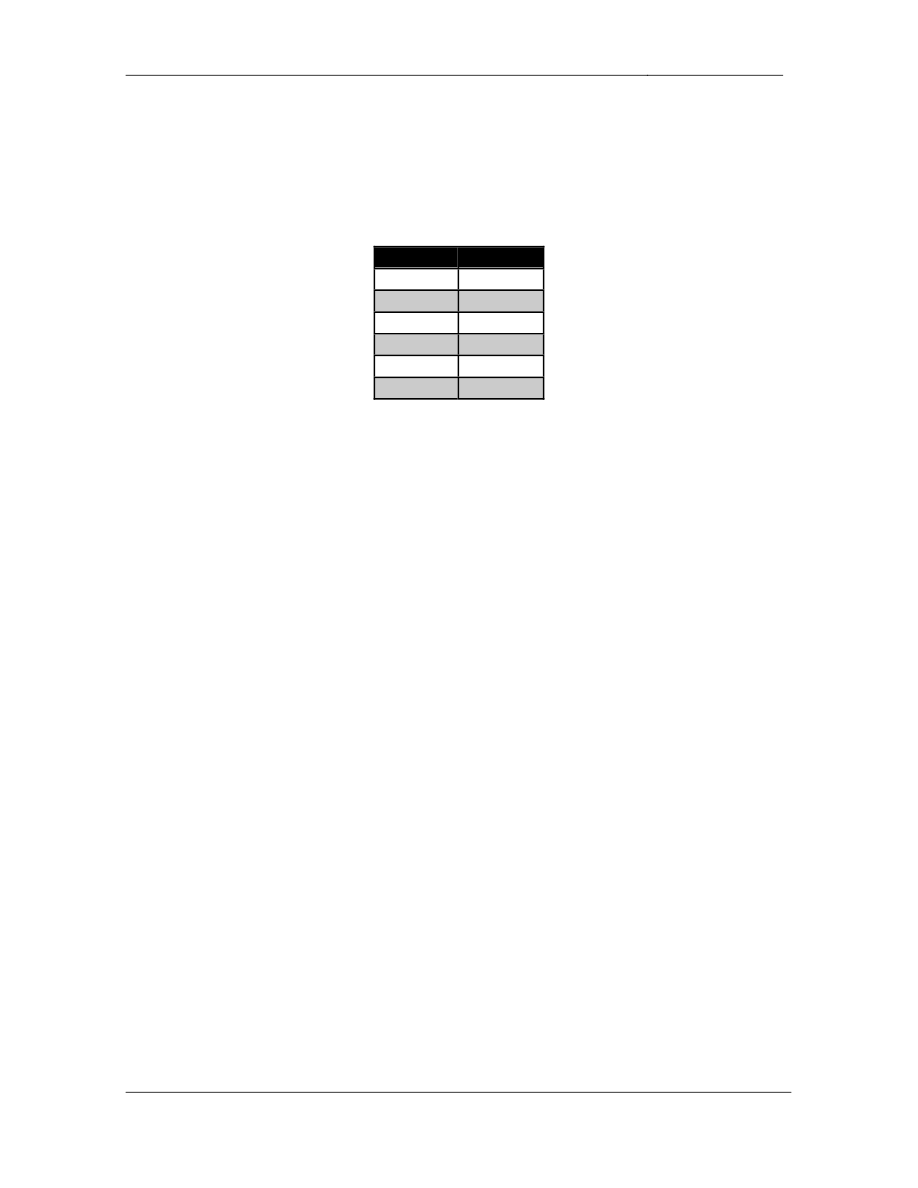
Point Values:
The point values for each section are as follows:
Section
Point Value
Bridging & Switching
17
WAN Technologies
8
Interior Gateway Routing
24
Exterior Gateway Routing
10
IP Multicast
6
IPv6
7
QoS
9
Security
5
System Management
7
IP Services
7
GOOD LUCK!

CCIE Routing & Switching Lab Workbook Version 4.0
Lab 9
Copyright © 2007 Internetwork Expert
www.InternetworkExpert.com
- 181 -
Note:
• There are no faults in the initial configurations
• Do not alter the commands in the initial configurations
1. Bridging & Switching
1.1. Trunking
• Configure
three
dot1q
trunks
between
SW1’s
interfaces
Fa0/13
through
Fa0/15, and SW2’s interface Fa0/13 through Fa0/15.
• For
ease
of
administration
refer
to
these
trunks
with
the
interface
macro
DOT-ONE-Q.
2 Points
1.2. Trunking
• Configure
one
logical
dot1q
trunk
between
SW2’s
interfaces
Fa0/16
through Fa0/18, and SW3’s interface Fa0/16 through Fa0/18.
2 Points
1.3. Trunking
• Configure
two
trunks
between
SW3’s
interfaces
Fa0/19
through
Fa0/20,
and SW4’s interface Fa0/19 through Fa0/20.
• SW4
should
initiate
these
trunks
dynamically.
• All
traffic
sent
over
these
trunk
links
should
include
a
32
bit
tag.
2 Points
1.4. VLAN Assignments
• Configure
the
switches
to
be
in
VTP
transparent
mode.
• Using
the
VLAN
information
provided
in
the
diagram
create
the
VLANs
and assign them to the appropriate switch ports.
• Each
switch
should
be
aware
of
the
minimum
number
of
VLANs
needed.
4 Points

CCIE Routing & Switching Lab Workbook Version 4.0
Lab 9
Copyright © 2007 Internetwork Expert
www.InternetworkExpert.com
- 182 -
1.5. Spanning-Tree Filtering
• Recently
the
administrators
in
your
NOC
have
reported
strange
traffic
patterns throughout your switch block. After further investigation you have
discovered that one of your customer’s switches connected to port Fa0/24
on SW2 has been advertising superior BPDUs into your network. After
talking to your customer’s engineers the problem has been resolved, but
your management is concerned about this happening again in the future.
• Configure
SW2
so
that
port
Fa0/24
is
disabled
if
this
problem
occurs
again.
2 Points
1.6. Spanning-Tree
• Configure
SW2
to
match
the
highlighted
command
output
below:
Rack1SW2#show spanning-tree vlan 68
VLAN0068
Spanning tree enabled protocol ieee
Root ID Priority 24644
Address 0016.9d31.8380
This bridge is the root
Hello Time 1 sec Max Age 7 sec Forward Delay 5 sec
• Use
the
fewest
commands
needed
to
accomplish
this
task.
2 Points
1.7. Etherchannel
• Configure
a
logical
layer
3
etherchannel
link
between
SW3
and
SW4
using
the Fa0/14 and Fa0/15 connect to SW1 on each switch.
• Use
the
IP
addressing
and
PortChannel
number
from
the
diagram.
• If
an
additional
VLAN
is
needed
use
VLAN
100.
3 Points

CCIE Routing & Switching Lab Workbook Version 4.0
Lab 9
Copyright © 2007 Internetwork Expert
www.InternetworkExpert.com
- 183 -
2. WAN Technologies
2.1. Partial Mesh
• Configure
a
partially
meshed
Frame
Relay
network
between
R1,
R2,
R3,
and R4.
• Use
only
the
DLCIs
specified
in
the
diagram.
• Do
not
use
Frame
Relay
Inverse-ARP.
• Do
not
use
the frame-relay map command on R3 or R4.
• Ensure
that
all
devices
on
the
Frame
Relay
network
have
IP
reachability
to each other.
2 Points
2.2. Point-to-Point
• Configure
the
Frame
Relay
connection
between
R3
and
R5.
• Do
not
use
subinterfaces
on
either
R3
or
R5.
• Do
not
use
the
frame-relay map command on either R3 or R5.
• Do
not
allow
Inverse-ARP
requests
to
be
sent
out
any
DLCIs
other
than
315 and 513.
2 Points
2.3. Point-to-Point
• Configure
the
Frame
Relay
connection
between
R6
and
BB1
per
the
diagram.
• Use
only
the
main
interface
on
R6.
• Do
not
use
Frame
Relay
Inverse-ARP
for
layer
3
to
layer
2
resolution.
2 Points

CCIE Routing & Switching Lab Workbook Version 4.0
Lab 9
Copyright © 2007 Internetwork Expert
www.InternetworkExpert.com
- 184 -
2.4. Network Redundancy
• A
point-to-point
Serial
link
has
been
provisioned
between
R4
and
R5
in
order to maintain connectivity in the case that R4 loses its connection to
the Frame Relay cloud.
• Configure
the
network
so
that
if
the
line
protocol
of
R4’s
subinterface
goes
down this interface becomes active.
• Once
R4
regains
its
connection
to
the
Frame
Relay
cloud
it
should
wait
for
5 minutes before shutting the Serial link down.
2 Points
CCIE Routing & Switching Lab Workbook Version 4.0
Lab 9
Copyright © 2007 Internetwork Expert
www.InternetworkExpert.com
- 185 -
3. Interior Gateway Routing
3.1. OSPF
• Configure
OSPF
area
168
on
the
following
devices
and
interfaces:
Device
Interface
R1
Fa0/0
R6
G0/0
R6
G0/1
SW2
VLAN 8
SW2
VLAN 18
SW2
VLAN 68
• In
order
to
help
offload
some
of
the
OSPF
related
processing
ensure
that
SW2 is always elected the DR in both VLAN 18 and VLAN 68.
• Advertise
the
Loopback
0
interfaces
of
R1,
R6,
and
SW2
into
OSPF
area
168.
2 Points
3.2. OSPF
• After
a
recent
network
audit
an
outside
consultant
have
reported
that
some of the company’s non-Cisco devices have been sending type 6
LSAs into VLAN 18. After examining the logs on R1 and SW2 the network
administrator has confirmed that R1 and SW2 have been receiving type 6
LSAs.
• Configure
R1
and
SW2
to
stop
generating
log
messages
when
a
type
6
LSA is received.
2 Points

CCIE Routing & Switching Lab Workbook Version 4.0
Lab 9
Copyright © 2007 Internetwork Expert
www.InternetworkExpert.com
- 186 -
3.3. OSPF
• In
order
to
ensure
that
false
routing
information
is
not
injected
into
the
OSPF domain from VLAN 18 configure R1 and SW2 to authenticate all
adjacencies established on this segment.
• Do
not
use
the
ip ospf authentication message-digest command to
accomplish this.
• R1
and
SW2
should
use
the
MD5
key
number
7,
and
ensure
that
the
password is stored in both devices’ configuration in a pre-encrypted form.
• Ensure
that
SW2
does
not
authenticate
the
OSPF
neighbor
relationship
with R6.
2 Points
3.4. EIGRP
• Enable
EIGRP
AS
100
on
R3,
R4,
R5,
and
SW1.
EIGRP
AS
100
was
enabled on SW3 and SW4 in the initial configurations.
• Enable
EIGRP
on
the
Serial
connection
between
R4
and
R5.
• Enable
EIGRP
on
the
Frame
Relay
link
between
R3
and
R5.
• Enable
EIGRP
on
the
Ethernet
segments
between
R3
&
SW3,
R5
&
SW1,
and SW1 & SW4.
• Configure
R5
to
advertise
the
148.X.5.0/24
network
via
EIGRP.
• Configure
SW1
to
advertise
VLAN
77
via
EIGRP.
• Configure
R5,
and
SW1
to
advertise
their
Loopback
0
interfaces
via
EIGRP.
2 Points
3.5. EIGRP
• In
order
to
help
the
network
converge
faster
in
the
event
of
the
Frame
Relay link failing configure R3 and R5 to declare their neighbor
relationship dead if they have not received an EIGRP hello in 12 seconds.
2 Points

CCIE Routing & Switching Lab Workbook Version 4.0
Lab 9
Copyright © 2007 Internetwork Expert
www.InternetworkExpert.com
- 187 -
3.6. EIGRP
• The
network
administrator
has
requested
that
R5
and
SW1
authenticate
each other using the password of CISCO2005.
• For
added
security
R5
and
SW1
should
rotate
their
keys
used
for
this
authentication. This key rotation should occur at 11:45 PM Dec 31st,
2005.
• The
new
key
to
use
for
authentication
is
CISCO2006.
• To
help
ensure
that
R5
and
SW1’s
key
rotation
does
not
result
in
a
network outage allow for the both keys to be accepted 30 minutes prior to
and after the scheduled key rotation time.
2 Points
3.7. RIP
• Configure
RIP
on
SW1.
• Enable
RIP
on
VLAN
73.
• BB3
is
configured
to
send
and
receive
only
RIPv2
updates,
however
there
is also a legacy Linux server located on this segment that only accepts
RIPv1 updates. Ensure that SW1 can support both of these clients on
VLAN 73.
2 Points
3.8. RIP
• Configure
RIPv2
on
R1,
R2,
R3,
and
R4.
• Enable
RIP
on
the
Frame
Relay
cloud
between
these
four
routers.
• Enable
RIP
on
VLAN
232
between
R2
and
R3.
• Advertise
R2,
R3,
and
R4’s
Loopback
0
interfaces
via
RIP.
1 Point
3.9. RIP
• The
network
administrator
has
noticed
that
BB2
is
sending
RIP
updates
into VLAN 232. After several failed attempts to contact the team
responsible for managing BB2 your network administrator has requested
that R2 and R3 not receive any RIP updates sourced from BB2.
• This
configuration
should
not
be
performed
on
R2
or
R3.
2 Points

CCIE Routing & Switching Lab Workbook Version 4.0
Lab 9
Copyright © 2007 Internetwork Expert
www.InternetworkExpert.com
- 188 -
3.10. Network Migration
• Without
removing
or
altering
the
EIGRP
configuration
migrate
SW3
and
SW4 to RIPv2.
• SW3
and
SW4
should
use
RIPv2
for
reachability
to
the
rest
of
the
network
but the rest of the network should use EIGRP for reachability to the
Ethernet segment between them and their Loopback0 subnets.
• SW3
and
SW4
should
use
EIGRP
routes
for
reachability
to
subnets
within
the 150.X.0.0/16 network.
• R3
and
SW1
should
run
RIPv2
with
SW3
and
SW4
respectively
along
with
EIGRP.
3 Points
3.11. IGP Redistribution
• Redistribute
between
RIP
and
OSPF
on
R1.
• Redistribute
between
RIP
and
EIGRP
on
R3.
• When
R4’s
connection
to
the
Frame
Relay
cloud
is
down
the
only
IGP
route it should see is a default route pointing to R5.
• Ensure
that
all
devices
have
connectivity
to
R4’s
HDLC
and
Loopback
0
networks when its Frame Relay connection is down.
• You
are
allowed
one
static
route
to
accomplish
this
if
needed.
2 Points
3.12. IGP Redistribution
• Redistribute
between
RIP
and
EIGRP
on
SW1.
• To
alleviate
possible
routing
issues
with
the
Linux
server
and
BB3
configure SW1 so that these devices cannot advertise routes learned from
SW1 onto other RIP speaking devices.
• Do
not
use
an
offset-list to accomplish this.
2 Points

CCIE Routing & Switching Lab Workbook Version 4.0
Lab 9
Copyright © 2007 Internetwork Expert
www.InternetworkExpert.com
- 189 -
4. Exterior Gateway Routing
4.1. BGP Peering
• Without
adding
additional
BGP
peering
sessions
ensure
that
BGP
updates
are received by all BGP enabled routers.
• Configure
R2
and
R3
to
authenticate
their
BGP
peering
sessions
with
each other and BB2 using the password CISCO.
2 Points
4.2. BGP Filtering
• Network
monitoring
engineers
in
your
NOC
have
reported
that
R6
is
dangerously low on memory. You have determined that a large BGP table
is consuming all of R6’s memory. In order to reduce the amount of
memory required by the BGP process configure R6 to only accept prefixes
from BB1 that have been originated by themselves and their directly
connected customers.
2 Points
4.3. BGP Summarization
• Configure
R4
to
advertise
the
10.X.4.0/24
subnet
into
BGP.
• Ensure
that
the
10.X.4.0/24
prefix
shows
up
on
R1
as
10.0.0.0/8.
• Do
not
use
the
aggregate address or network command to accomplish
this task.
2 Points

CCIE Routing & Switching Lab Workbook Version 4.0
Lab 9
Copyright © 2007 Internetwork Expert
www.InternetworkExpert.com
- 190 -
4.4. BGP Summarization
• Configure
R6
to
advertise
an
aggregate
of
your
internal
address
space
as
well as the 54.X.3.0/24 subnet into BGP.
• Since
the
Frame
Relay
link
is
AS
54’s
only
connection
to
your
network
it
does not need specific subnet information about your address space.
• Configure
your
network
so
that
BB1
has
the
minimum
amount
of
information necessary to obtain reachability to your network.
• Do
not
use
either
the
default-originate or
summary-only keywords to
accomplish this.
2 Points
4.5. BGP Filtering
• Create
an
additional
Loopback
interface
on
SW1
using
the
148.X.177.0/24
subnet and advertise it into BGP.
• This
prefix
should
not
be
advertised
outside
of
AS
65057.
• Ensure
that
R5
still
has
reachability
to
this
network.
• All
of
this
configuration
should
be
done
on
SW1.
2 Points

CCIE Routing & Switching Lab Workbook Version 4.0
Lab 9
Copyright © 2007 Internetwork Expert
www.InternetworkExpert.com
- 191 -
5. IP Multicast
5.1. PIM
• Configure
IP
Multicast
routing
on
R1,
R2,
R3,
R6,
and
SW2.
• Configure
PIM
dense
mode
on
the
Frame
Relay
segment
between
R1,
R2, and R3.
• Configure
PIM
dense
mode
on
VLAN
18
between
R1
and
SW2.
• Configure
PIM
dense
mode
on
VLAN
68
between
R6
and
SW2.
• Configure
PIM
dense
mode
on
VLANs
3
and
6
of
R3
and
R6
respectively.
2 Points
5.2. Multicast Testing
• A
Windows
media
server
located
on
VLAN
3
is
streaming
a
multicast
video feed into your network. You have received complaints from users in
VLAN 6 that they are unable to receive these feeds.
• Configure
the
network
to
resolve
this
problem.
• For
further
testing
purposes
ensure
that
R6
responds
to
ICMP
echo
requests sent to the multicast group 224.6.6.6 sourced from VLAN 3.
2 Points
5.3. Multicast RPF
• Your
NOC
engineers
have
reported
excessively
high
CPU
utilization
on
R2. While investigating the problem you have noticed that various
unstable unicast routes are causing excessive amounts of triggered RPF
checks.
• In
order
to
help
alleviate
this
problem
configure
R2
so
that
it
waits
at
least
300ms between consecutive RPF checks.
2 Points

CCIE Routing & Switching Lab Workbook Version 4.0
Lab 9
Copyright © 2007 Internetwork Expert
www.InternetworkExpert.com
- 192 -
6. IPv6
6.1. IPv6 Addressing
• Configure
IPv6
processing
on
R3,
R4,
R5,
and
R6.
• Configure
the
Loopback
0
interfaces
of
these
devices
with
the
IPv6
addresses 2002:ZZZZ:ZZZZ::Y/64, where ZZZZ:ZZZZ is the IPv4 address
of the router’s Loopback 0 interface and Y is the router number.
• Configure
VLANs
3,
4,
5,
and
6
with
the
IPv6
addresses
2002:ZZZZ:ZZZZ:1::Y/64, where ZZZZ:ZZZZ is the IPv4 address of the
router’s Loopback 0 interface and Y is the router number.
2 Points
6.2. IPv6 Tunneling
• Hosts
on
VLANs
3,
4,
5,
and
6
need
to
communicate
with
each
other
via
IPv6, however you don’t want to enable IPv6 on every device in the transit
path between these devices. In addition to this you do not want to have to
maintain manual point-to-point tunnel configurations as more IPv6 enabled
segments come on to your network.
• Configure
R3,
R4,
R5,
and
R6
in
such
a
way
to
allow
fully
meshed
connectivity between their IPv6 enabled VLANs.
• This
configuration
should
dynamically
account
for
new
IPv6
enabled
segments being added in the future.
• You
are
allowed
one
non-default
static
IPv6
route
on
each
of
these
devices to accomplish this.
3 Points
6.3. IPv6 Filtering
• Recent
network
monitoring
has
indicated
numerous
failed
attempts
to
telnet to R6 via IPv6.
• In
order
to
prevent
unauthorized
access
to
R6
configure
the
network
so
that only your PC is allowed to start telnet sessions to the command line of
R6.
• Do
not
use
the
ipv6 traffic-filter command to accomplish this.
• Your
PC
is
located
on
VLAN
6
and
has
a
host
address
of
0209:6BFF:FE06:47EF.
2 Points

CCIE Routing & Switching Lab Workbook Version 4.0
Lab 9
Copyright © 2007 Internetwork Expert
www.InternetworkExpert.com
- 193 -
7. QoS
7.1. Frame Relay Traffic Shaping
• Your
company
has
recently
purchased
a
5Mbps
Internet
connection
from
the Frame Relay provider to BB1. However, the lowest speed interface
that the provider supports to accommodate this connection is DS3.
• To
prevent
the
dropping
of
your
traffic
configure
R6
network
so
that
traffic
sent out to BB1 does not exceed 5Mbps on average.
• The
provider
has
agreed
to
allow
you
to
burst
up
to
7.5Mbps
for
a
maximum period of 32ms.
• Do
not
use
the
frame-relay traffic-shaping command to accomplish this.
3 Points
7.2. Policing
• After
implementing
traffic
shaping
the
help
desk
has
been
getting
a
lot
of
complaints about slow network performance. After further investigation it
appears that someone inside your network is sharing files through a peer-
to-peer file sharing application. Instead of blocking this traffic your design
team has suggested that you police this type of traffic to the lowest values
possible. Therefore, users attempting to download files from your network
will become frustrated and give up.
• Ensure
to
include
KaZaA,
Morpheus,
BearShare,
and
LimeWire
traffic
in
this policy.
3 Points
7.3. Congestion Management
• Even
after
implementing
the
above
policy
your
administrators
have
still
been getting numerous complaints from users about slow network
response time. The majority of these users are complaining that it is
taking a very long time to send e-mail and access the web.
• In
order
to
increase
performance
for
these
users
configure
R6
so
that
HTTP traffic is guaranteed a minimum of 2Mbps of the output queue on
the Frame Relay link, while SMTP traffic is guaranteed a minimum of
1Mbps of the output queue.
2 Points

CCIE Routing & Switching Lab Workbook Version 4.0
Lab 9
Copyright © 2007 Internetwork Expert
www.InternetworkExpert.com
- 194 -
7.4. Congestion Management
• After
the
last
addition
to
your
QoS
policy
your
administrators
have
reported that the number of complaints from network users has dropped
dramatically. However, now you have noticed that the ping time to #ccie
on irc.internetworkexpert.com is horribly slow.
• In
order
to
decrease
your
latency
to
the
channel
configure
R6
so
that
up
to
32Kbps of your IRC traffic (TCP 6667) is dequeued first out the Frame
Relay link to the Internet.
• Your
PC’s
IP
address
is
148.1.6.10.
2 Points
8. Security
8.1. DoS Filtering
• Recently
the
administrators
in
your
NOC
have
notified
you
that
an
excessive number of ICMP packets are being received on the Frame
Relay link to the Internet. After further investigation you have determined
that you are undergoing a DoS attack which is originating from spoofed
private addresses.
• In
order
to
reduce
the
impact
of
this
attack
on
your
internal
network
configure R6 so that it does not accept traffic from the Internet if it is
sourced from these hosts as defined in RFC 1918.
2 Points
8.2. Traffic Filtering
• Recently
application
monitoring
has
shown
that
users
on
VLAN
5
have
been excessively surfing the Internet during work hours. In response to
this your manager has requested that you configure R5 to block these
users’ activities so that they can only go to your internal web server at
148.X.3.100.
• After
work
hours
these
users
should
be
allowed
full
access.
• Work
hours
are
from
9
AM
to
5
PM
Monday
through
Friday.
• Use
the
minimum
amount
of
access-list
entries
to
accomplish
this.
3 Points

CCIE Routing & Switching Lab Workbook Version 4.0
Lab 9
Copyright © 2007 Internetwork Expert
www.InternetworkExpert.com
- 195 -
9. System Management
9.1. Crash Logging
• One
of
your
network
administrators
has
reported
that
R6
has
been
experiencing random crashes. After consulting with TAC they have
recommended that a core dump be captured from R6 if it crashes again.
• Configure
R6
to
send
a
core
dump
via
FTP
to
the
server
148.X.3.100.
• The
file
name
to
send
is
R6DUMP.txt.
• Use
the
username
R6CORE
and
the
password
CISCO
when
sending
this
file to the FTP server.
2 Points
9.2. NTP
• Recently
there
was
a
brief
network
outage
due
to
a
misconfiguration
in
the
EIGRP authentication between R5 and SW1. After further investigation
you have verified that the configuration was correct, but it appears that the
system clocks were not consistent between R5 and SW1. In order to
prevent this problem in the future, you have decided to implement Network
Time Protocol on R5 and SW1.
• Configure
R5
and
SW1
to
get
network
time
from
BB3.
• In
the
case
that
BB3
is
unreachable
R5
and
SW1
should
be
able
to
maintain consistent time amongst themselves.
3 Points
9.3. NTP Authentication
• To
ensure
the
legitimacy
of
their
time
sources
configure
R5
and
SW1
to
authenticate the NTP information coming from BB3 using an MD5 hash of
the password CISCO.
2 Points

CCIE Routing & Switching Lab Workbook Version 4.0
Lab 9
Copyright © 2007 Internetwork Expert
www.InternetworkExpert.com
- 196 -
10. IP Services
10.1. TCP Session Establishment
• While
telneting
to
one
of
your
network
devices
from
R1
you
accidentally
mistyped the IP address and were forced to wait 30 second for the router
to return to the CLI prompt.
• In
order
to
avoid
this
long
delay
configure
R1
to
cancel
a
TCP
request
if
the session has not reached the established state within 5 seconds.
2 Points
10.2. Traffic Monitoring
• For
capacity
planning
purposes
your
manager
would
like
to
know
which
hosts are sending the most traffic out the Frame Relay link to BB1.
• Configure
R6
to
collect
these
statistics
for
your
manager
and
store
them
locally.
• To
ensure
that
this
configuration
does
not
negatively
impact
your
network
do not allow R6 to store more than 1000 entries.
2 Points
10.3. NAT Load Balancing
• Recent
utilization
monitoring
on
your
internal
web
server
has
shown
that
it
is becoming overloaded with HTTP requests. In order to alleviate
congestion and speed up response time three new servers have been
installed on VLAN 3.
• Configure
NAT
on
R3
so
that
traffic
is
transparently
load
balanced
between these new servers without having to inform the users of the
server change.
• The
old
web
server’s
address
was
148.X.3.100.
• The
new
server
addresses
are
148.X.3.110,
148.X.3.111,
and
148.X.3.112.
• These
servers
support
web
requests
at
ports
80,
443,
and
8080.
3 Points
Wyszukiwarka
Podobne podstrony:
IE RS lab 18 overview
IE RS Lab 16 overview
IE RS lab 17 overview
IE RS lab 10 overview
IE RS lab 11 overview
IE RS lab 20 overview
IE RS lab 13 overview
IE RS lab 15 overview
IE RS lab 19 overview
IE RS lab 11 solutions
IE RS lab 10 solutions
IE RS lab 12 solutions
IE RS lab 18 Diagram
IE RS lab 9 solutions
IE RS lab 11 diagram
IE RS lab 20 diagram
IE RS lab 19 diagram
IE RS lab 8 diagram
IE RS lab 13 solutions
więcej podobnych podstron