COSMOSM Basic FEA System
1
1
About the Verification Problems...
. . . . . . . . . . . . . . . . . 1-1
Linear Static Analysis
. . . . . . . . . . . . . . . . . . . . . . . . . . . 2-1
Introduction . . . . . . . . . . . . . . . . . . . . . . . . . . . . . . . . . . . . . . . . . . . . . 2-1
S1: Pin Jointed Truss . . . . . . . . . . . . . . . . . . . . . . . . . . . . . . . . . . . . . . . . . . .2-6
S2: Long Thick-Walled Cylinder . . . . . . . . . . . . . . . . . . . . . . . . . . . . . . . . .2-7
S3A, S3B: Simply Supported Rectangular Plate . . . . . . . . . . . . . . . . . . . . . .2-9
S4: Thermal Stress Analysis of a Truss Structure . . . . . . . . . . . . . . . . . . . .2-10
S5: Thermal Stress Analysis of a 2D Structure . . . . . . . . . . . . . . . . . . . . . .2-12
S6A, S6B: Deflection of a Cantilever Beam . . . . . . . . . . . . . . . . . . . . . . . .2-13
S7: Beam Stresses and Deflections . . . . . . . . . . . . . . . . . . . . . . . . . . . . . . .2-14
S8: Tip Displacements of a Circular Beam . . . . . . . . . . . . . . . . . . . . . . . . .2-15
S9A: Clamped Beam Subject to Imposed Displacement . . . . . . . . . . . . . .2-16
S9B: Clamped Beam Subject to Imposed Rotation . . . . . . . . . . . . . . . . . . .2-18
S10A, S10B: Bending of a Solid Beam . . . . . . . . . . . . . . . . . . . . . . . . . . . .2-19
S11: Thermal Stress Analysis of a 3D Structure . . . . . . . . . . . . . . . . . . . . .2-21
S12: Deflection of a Hinged Support . . . . . . . . . . . . . . . . . . . . . . . . . . . . .2-22
S13: Statically Indeterminate Reaction Force Analysis . . . . . . . . . . . . . . .2-23
S14A, S14B: Space Truss with Vertical Load . . . . . . . . . . . . . . . . . . . . . .2-24
S15: Out-of-Plane Bending of a Curved Bar . . . . . . . . . . . . . . . . . . . . . . . .2-25
S16A, S16B: Curved Pipe Deflection . . . . . . . . . . . . . . . . . . . . . . . . . . . . .2-26
S17: Rectangular Plate Under Triangular Thermal Loading . . . . . . . . . . . .2-28
S18: Hemispherical Dome Under Unit Moment Around Free Edge . . . . .2-29
In
de
x
In
de
x

Contents
2
COSMOSM Basic FEA System
S19: Hollow Thick-walled Cylinder Subject to Temperature
and Pressure . . . . . . . . . . . . . . . . . . . . . . . . . . . . . . . . . . . . . . . . . . . . . . . . .2-30
S20A, S20B: Cylindrical Shell Roof . . . . . . . . . . . . . . . . . . . . . . . . . . . . . .2-31
S21A, S21B: Antisymmetric Cross-Ply Laminated Plate (SHELL4L) . . . .2-33
S22: Thermally Loaded Support Structure . . . . . . . . . . . . . . . . . . . . . . . . .2-35
S23: Thermal Stress Analysis of a Frame . . . . . . . . . . . . . . . . . . . . . . . . . .2-36
S24: Thermal Stress Analysis of a Simple Frame . . . . . . . . . . . . . . . . . . . .2-38
S25: Torsion of a Square Box Beam . . . . . . . . . . . . . . . . . . . . . . . . . . . . . .2-39
S26: Beam With Elastic Supports and a Hinge . . . . . . . . . . . . . . . . . . . . . .2-41
S27: Frame Analysis with Combined Loads . . . . . . . . . . . . . . . . . . . . . . . .2-43
S28: Cantilever Unsymmetric Beam . . . . . . . . . . . . . . . . . . . . . . . . . . . . . .2-45
S29A, S29B: Square Angle-Ply Composite Plate Under Sinusoidal
Loading . . . . . . . . . . . . . . . . . . . . . . . . . . . . . . . . . . . . . . . . . . . . . . . . . . . .2-47
S30: Effect of Transverse Shear on Maximum Deflection . . . . . . . . . . . . .2-48
S31: Square Angle-Ply Composite Plate Under Sinusoidal Loading . . . . .2-50
S32A, S32B, S32C, S32D, S32M: Substructure of a Tower . . . . . . . . . . .2-51
S33A, S33M: Substructure of an Airplane (Wing) . . . . . . . . . . . . . . . . . . .2-53
S34: Tie Rod with Lateral Loading . . . . . . . . . . . . . . . . . . . . . . . . . . . . . . .2-54
S35A, S35B: Spherical Cap Under Uniform Pressure (Solid) . . . . . . . . . .2-56
S36A, S36M: Substructure of a Simply Supported Plate . . . . . . . . . . . . . .2-58
S37: Hyperboloidal Shell Under Uniform Ring Load Around Free Edge .2-60
S38: Rotating Solid Disk . . . . . . . . . . . . . . . . . . . . . . . . . . . . . . . . . . . . . . .2-62
S39: Unbalanced Rotating Flywheel . . . . . . . . . . . . . . . . . . . . . . . . . . . . . .2-63
S40: Truss Structure Subject to a Concentrated Load . . . . . . . . . . . . . . . . .2-64
S41: Reactions of a Frame Structure . . . . . . . . . . . . . . . . . . . . . . . . . . . . . .2-65
S42A, S42B: Reactions and Deflections of a Cantilever Beam . . . . . . . . .2-66
S43: Bending of a T Section Beam . . . . . . . . . . . . . . . . . . . . . . . . . . . . . . .2-67
S44A, S44B: Bending of a Circular Plate with a Center Hole . . . . . . . . . .2-68
S45: Eccentric Frame . . . . . . . . . . . . . . . . . . . . . . . . . . . . . . . . . . . . . . . . .2-70
S46, S46A, S46B: Bending of a Cantilever Beam . . . . . . . . . . . . . . . . . . .2-71
S47, S47A, S47B: Bending of a Cantilever Beam . . . . . . . . . . . . . . . . . . .2-73
S48: Rotation of a Tank of Fluid (PLANE2D Fluid) . . . . . . . . . . . . . . . . .2-75
S49A, S49B: Acceleration of a Tank of Fluid (PLANE2D Fluid) . . . . . . .2-77
S50A, S50B, S50C, S50D, S50F, S50G, S50H, S50I: Deflection
of a Curved Beam . . . . . . . . . . . . . . . . . . . . . . . . . . . . . . . . . . . . . . . . . . . .2-79
In
de
x
In
de
x

COSMOSM Basic FEA System
3
Part 2 Verification Problems
S51: Gable Frame with Hinged Supports . . . . . . . . . . . . . . . . . . . . . . . . . . 2-80
S52: Support Reactions for a Beam with Intermediate Forces
and Moments . . . . . . . . . . . . . . . . . . . . . . . . . . . . . . . . . . . . . . . . . . . . . . . 2-81
S53: Beam Analysis with Intermediate Loads . . . . . . . . . . . . . . . . . . . . . . 2-83
S54: Analysis of a Plane Frame with Beam Loads . . . . . . . . . . . . . . . . . . 2-85
S55: Laterally Loaded Tapered Beam . . . . . . . . . . . . . . . . . . . . . . . . . . . . 2-86
S56: Circular Plate Under a Concentrated Load (SHELL9 Element) . . . . 2-87
S57: Test of a Pinched Cylinder with Diaphragm (SHELL9 Element) . . . 2-89
S58A, S58B, S58C: Deflection of a Twisted Beam with Tip Force . . . . . 2-91
S59A, S59B, S59C: Sandwich Square Plate Under Uniform Loading
(SHELL9L) . . . . . . . . . . . . . . . . . . . . . . . . . . . . . . . . . . . . . . . . . . . . . . . . 2-93
S60: Clamped Square Plate Under Uniform Loading . . . . . . . . . . . . . . . . 2-95
S61: Single-Edge Cracked Bend Specimen, Evaluation of Stress Intensity
Factor Using Crack Element . . . . . . . . . . . . . . . . . . . . . . . . . . . . . . . . . . . 2-97
S62: Plate with Central Crack . . . . . . . . . . . . . . . . . . . . . . . . . . . . . . . . . . 2-98
S63: Cyclic Symmetry Analysis of a Hexagonal Frame . . . . . . . . . . . . . . 2-99
S64A, S64B: Cyclic Symmetry . . . . . . . . . . . . . . . . . . . . . . . . . . . . . . . . 2-100
S65: Fluid-Structure Interaction, Rotation of a Tank of Fluid . . . . . . . . . 2-101
S66: Fluid-Structure Interaction, Acceleration of a Tank of Fluid . . . . . 2-103
S67: MacNeal-Harder Test . . . . . . . . . . . . . . . . . . . . . . . . . . . . . . . . . . . . 2-105
S68: P-Method Solution of a Square Plate with Hole . . . . . . . . . . . . . . . 2-106
S69: P-Method Analysis of an Elliptic Membrane Under Pressure . . . . . 2-107
S70: Thermal Analysis with Temperature Dependent Material . . . . . . . . 2-108
S71: Sandwich Beam with Concentrated Load . . . . . . . . . . . . . . . . . . . . 2-109
S74: Constant Stress Patch Test (TETRA4R) . . . . . . . . . . . . . . . . . . . . . 2-110
S75: Analysis of a Cantilever Beam with Gaps, Subject to Different
Loading Conditions . . . . . . . . . . . . . . . . . . . . . . . . . . . . . . . . . . . . . . . . . . 2-111
S76: Simply Supported Beam Subject to Pressure from
a Rigid Parabolic Shaped Piston . . . . . . . . . . . . . . . . . . . . . . . . . . . . . . . 2-113
S77: Bending of a Solid Beam Using Direct Material Matrix Input . . . . 2-115
S78: P-Adaptive Analysis of a Square Plate with a Circular Hole . . . . . 2-117
S79: Hemispherical Shell Under Unit Moment Around Free Edge . . . . . 2-119
S80: Axisymmetric Hyperbolic Shell Under a Cosine Harmonic
Loading on the Free Edge . . . . . . . . . . . . . . . . . . . . . . . . . . . . . . . . . . . . 2-120
S81: Circular Plate Under Non-Axisymmetric Load . . . . . . . . . . . . . . . . 2-121
In
de
x
In
de
x
Contents
4
COSMOSM Basic FEA System
S82: Twisting of a Long Solid Shaft . . . . . . . . . . . . . . . . . . . . . . . . . . . . .2-123
S83: Bending of a Long Solid Shaft . . . . . . . . . . . . . . . . . . . . . . . . . . . . .2-125
S84: Submodeling of a Plate . . . . . . . . . . . . . . . . . . . . . . . . . . . . . . . . . . .2-127
S85: Plate on Elastic Foundation . . . . . . . . . . . . . . . . . . . . . . . . . . . . . . . .2-128
S86: Plate with Coupled Degrees of Freedom . . . . . . . . . . . . . . . . . . . . .2-129
S87: Gravity Loading of ELBOW Element . . . . . . . . . . . . . . . . . . . . . . .2-130
S88A, S88B: Single-Edge Cracked Bend Specimen, Evaluation of Stress
Intensity Factor Using the J-integral . . . . . . . . . . . . . . . . . . . . . . . . . . . . .2-131
S89A, S89B: Slant-Edge Cracked Plate, Evaluation of Stress
Intensity Factors Using the J-integral . . . . . . . . . . . . . . . . . . . . . . . . . . . .2-133
S90A, S90B: Penny-Shaped Crack in Round Bar, Evaluation
of Stress Intensity Factor Using the J-integral . . . . . . . . . . . . . . . . . . . . .2-135
S91: Crack Under Thermal Stresses, Evaluation of Stress Intensity
Using the J-integral . . . . . . . . . . . . . . . . . . . . . . . . . . . . . . . . . . . . . . . . . .2-137
S92A, S92B: Simply Supported Rectangular Plate, Using Direct
Material Matrix Input . . . . . . . . . . . . . . . . . . . . . . . . . . . . . . . . . . . . . . . .2-139
S93: Accelerating Rocket . . . . . . . . . . . . . . . . . . . . . . . . . . . . . . . . . . . . .2-141
S94A, S94B, S94C: P-Method Solution of a Square Plate with
a Small Hole . . . . . . . . . . . . . . . . . . . . . . . . . . . . . . . . . . . . . . . . . . . . . . .2-143
S95A, S95B, S95C: P-Method Solution of a U-Shaped
Circumferential Groove in a Circular Shaft . . . . . . . . . . . . . . . . . . . . . . .2-146
Modal (Frequency) Analysis
. . . . . . . . . . . . . . . . . . . . . . 3-1
Introduction . . . . . . . . . . . . . . . . . . . . . . . . . . . . . . . . . . . . . . . . . . . . . 3-1
F1: Natural Frequencies of a Two-Mass Spring System . . . . . . . . . . . . . . . .3-3
F2: Frequencies of a Cantilever Beam . . . . . . . . . . . . . . . . . . . . . . . . . . . . .3-4
F3: Frequency of a Simply Supported Beam . . . . . . . . . . . . . . . . . . . . . . . .3-5
F4: Natural Frequencies of a Cantilever Beam . . . . . . . . . . . . . . . . . . . . . . .3-6
F5: Frequency of a Cantilever Beam with Lumped Mass . . . . . . . . . . . . . . .3-7
F6: Dynamic Analysis of a 3D Structure . . . . . . . . . . . . . . . . . . . . . . . . . . .3-8
F7A, F7B: Dynamic Analysis of a Simply Supported Plate . . . . . . . . . . . . .3-9
F8: Clamped Circular Plate . . . . . . . . . . . . . . . . . . . . . . . . . . . . . . . . . . . . .3-10
F9: Frequencies of a Cylindrical Shell . . . . . . . . . . . . . . . . . . . . . . . . . . . .3-11
F10: Symmetric Modes and Natural Frequencies of a Ring . . . . . . . . . . . .3-12
In
de
x
In
de
x

COSMOSM Basic FEA System
5
Part 2 Verification Problems
F11A, F11B: Eigenvalues of a Triangular Wing . . . . . . . . . . . . . . . . . . . . 3-13
F12: Vibration of an Unsupported Beam . . . . . . . . . . . . . . . . . . . . . . . . . . 3-14
F13: Frequencies of a Solid Cantilever Beam . . . . . . . . . . . . . . . . . . . . . . 3-15
F14: Natural Frequency of Fluid . . . . . . . . . . . . . . . . . . . . . . . . . . . . . . . . 3-16
F16A, F16B: Vibration of a Clamped Wedge . . . . . . . . . . . . . . . . . . . . . . 3-17
F17: Lateral Vibration of an Axially Loaded Bar . . . . . . . . . . . . . . . . . . . 3-19
F18: Simply Supported Rectangular Plate . . . . . . . . . . . . . . . . . . . . . . . . . 3-20
F19: Lowest Frequencies of Clamped Cylindrical Shell
for Harmonic No. = 6 . . . . . . . . . . . . . . . . . . . . . . . . . . . . . . . . . . . . . . . . . 3-21
F20A, F20B, F20C, F20D, F20E, F20F, F20G, F20H: Dynamic Analysis of
Cantilever Beam . . . . . . . . . . . . . . . . . . . . . . . . . . . . . . . . . . . . . . . . . . . . . 3-22
F21: Frequency Analysis of a Right Circular Canal of Fluid with Variable
Depth . . . . . . . . . . . . . . . . . . . . . . . . . . . . . . . . . . . . . . . . . . . . . . . . . . . . . 3-23
F22: Frequency Analysis of a Rectangular Tank of Fluid with
Variable Depth . . . . . . . . . . . . . . . . . . . . . . . . . . . . . . . . . . . . . . . . . . . . . . 3-25
F23: Natural Frequency of Fluid in a Manometer . . . . . . . . . . . . . . . . . . . 3-27
F24: Modal Analysis of a Piezoelectric Cantilever . . . . . . . . . . . . . . . . . . 3-29
F25: Frequency Analysis of a Stretched Circular Membrane . . . . . . . . . . 3-30
F26: Frequency Analysis of a Spherical Shell . . . . . . . . . . . . . . . . . . . . . . 3-31
F27A, F27B: Natural Frequencies of a Simply-Supported Square Plate . . 3-32
F28: Cylindrical Roof Shell . . . . . . . . . . . . . . . . . . . . . . . . . . . . . . . . . . . . 3-33
F29A, B, C: Frequency Analysis of a Spinning Blade . . . . . . . . . . . . . . . . 3-34
Buckling Analysis
. . . . . . . . . . . . . . . . . . . . . . . . . . . . . .4-1
Introduction . . . . . . . . . . . . . . . . . . . . . . . . . . . . . . . . . . . . . . . . . . . . . 4-1
B1: Instability of Columns . . . . . . . . . . . . . . . . . . . . . . . . . . . . . . . . . . . . . . 4-2
B2: Instability of Columns . . . . . . . . . . . . . . . . . . . . . . . . . . . . . . . . . . . . . . 4-3
B3: Instability of Columns . . . . . . . . . . . . . . . . . . . . . . . . . . . . . . . . . . . . . . 4-4
B4: Simply Supported Rectangular Plate . . . . . . . . . . . . . . . . . . . . . . . . . . . 4-5
B5A, B5B: Instability of a Ring . . . . . . . . . . . . . . . . . . . . . . . . . . . . . . . . . . 4-6
B6: Buckling Analysis of a Small Frame . . . . . . . . . . . . . . . . . . . . . . . . . . . 4-7
B7A, B7B: Instability of Frames . . . . . . . . . . . . . . . . . . . . . . . . . . . . . . . . . 4-9
B8: Instability of a Cylinder . . . . . . . . . . . . . . . . . . . . . . . . . . . . . . . . . . . . 4-10
B9: Simply Supported Stiffened Plate . . . . . . . . . . . . . . . . . . . . . . . . . . . . 4-11
In
de
x
In
de
x

Contents
6
COSMOSM Basic FEA System
B10: Stability of a Rectangular Frame . . . . . . . . . . . . . . . . . . . . . . . . . . . .4-12
B11: Buckling of a Stepped Column . . . . . . . . . . . . . . . . . . . . . . . . . . . . . .4-13
B12: Buckling Analysis of a Simply Supported Composite Plate . . . . . . .4-14
B13: Buckling of a Tapered Column . . . . . . . . . . . . . . . . . . . . . . . . . . . . . .4-15
B14: Buckling of Clamped Cylindrical Shell Under External Pressure
Using the Nonaxisymmetric Buckling Mode Option . . . . . . . . . . . . . . . . .4-16
B15A, B15B: Buckling of Simply-Supported Cylindrical Shell Under Axial
Load . . . . . . . . . . . . . . . . . . . . . . . . . . . . . . . . . . . . . . . . . . . . . . . . . . . . . . .4-18
In
de
x
In
de
x
COSMOSM Basic FEA System
1-1
1
About the Verification
Problems...
Introduction
COSMOSM software modules are continually in the process of extensive develop-
ment, testing, and quality assurance checks. New features and capabilities incorpo-
rated into the system are rigorously tested using verification examples and in-house
quality assurance problems. All verification problems are provided to the user
along with the software, and they are made available in the COSMOSM directory.
There are more than 150 verification problems for analysis modules in the Basic
System.
The purpose of this section is dual fold: to present many example problems that test
a combination of capabilities offered in the COSMOSM Basic System, and to pro-
vide a large number of verification problems that validate the basic modeling and
analysis features. The first part of this manual presented several fully described and
illustrated examples which cover few aspects of modeling and analysis limitations.
This part provides examples on many other analysis features of the Basic System.
The input files for all verification problems are provided in separate folders
(depending on the analysis type) in the “...\Vprobs” directory where “...” denotes
the COSMOSM directory.
In
de
x
In
de
x
Chapter 1 About the Verification Problems...
1-2
COSMOSM Basic FEA System
Folder
Analysis Type
Geostar
GEOSTAR modeling examples
Buckling
Linearized buckling analysis
AdvDynamics Linear dynamic response analysis
Emagnetic
Electromagnetic analysis
Frequency
Frequency (modal) analysis
Fatigue
Fatigue analysis
Nonlinear
Nonlinear dynamic analysis
Static
Linear static stress analysis
Thermal
Thermal (heat transfer) analysis (linear)
FFE
FFE modules
HFS
High frequency electromagnetic simulation
To use the verification problems, enter GEOSTAR and at the GEO> prompt, exe-
cute the command
Load... (FILE)
from the File menu. The following pages show a
listing of the verification problems based on analysis and element type’s.
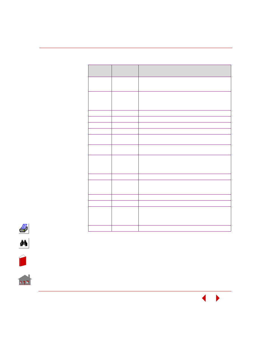
Classification by Analysis Type
Analysis
Type
Folder
Problem Title
Linear
Static
Analysis
...\Vprobs\Static
S1, S2, S3A, S3B, S4, S5, S6, S7, S8, S9A, S9B,S10A,
S10B, S11, S12, S13, S14A,S14B, S15, S16A, S16B,
S17, S18, S19, S20, S21A, S21B, S22, S23, S24, S25,
S26, S27, S28, S29, S29A, S30, S31, S31A, S32A, S32B,
S32C, S32D, S32M, S33A, S33M, S34, S35A, S35B,
S36A, S36M, S37, S38, S39, S40, S41, S42, S43, S44A,
S44B, S45, S46, S46A, S46B, S47, S47A, S47B, S48,
S49A, S49B, S50A, S50B, S50C, S50D, S50F, S50G,
S50H, S51, S52, S53, S54, S55, S56, S57, S58, S58B,
S59A, S59B, S59C, S60, S61, S62, S63, S64A, S64B,
S65, S66, S67, S68, S69, S70, S71, S74, S75, S76, S77,
S78, S79, S80, S81, S82, S83, S84, S85, S86, S87,
Buckling
Analysis
...\Vprobs\Buckling
B1, B2, B3, B4, B5A, B5B, B6, B7A, B7B, B8, B9, B10,
B11, B12, B13, B14, B15A, B15B
Modal
Analysis
...\Vprobs\Frequency
F1, F2, F3, F4, F5, F6, F7, F8, F9, F10, F11A, F11B, F12,
F13, F14, F16A, F16B, F17, F18, F19, F20A, F20B, F20C,
F20D, F20, F20E, F20G, F20F, F21, F22, F23, F24, F25,
F26, F27, F28
In
de
x
In
de
x
COSMOSM Basic FEA System
1-3
Part 2 Verification Problems
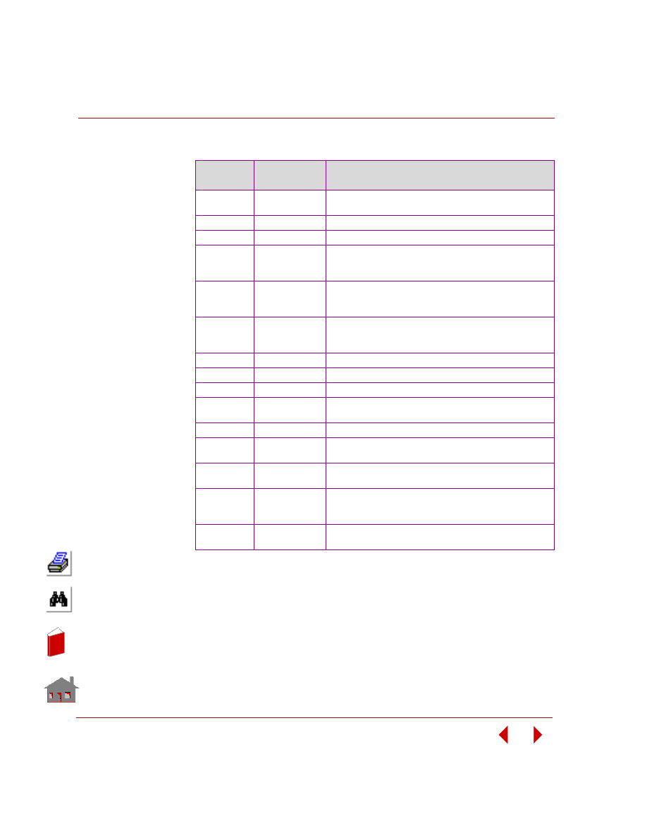
Classification by Element Type
Element
Name
Analysis Type
Problem Title
BEAM2D
Buckling
Linear Static
B10, B11, B13
S9A, S9B, S24, S41, S46, S47, S51, S52, S53, S54, S75,
S76
BEAM3D
Buckling
Modal Analysis
Linear Static
B1, B2, B3, B6, B9
F3, F4, F5, F12, F17
S7, S22, S23, S26, S27, S28, S33A, S33M, S34, S39, S43,
S45, S55
BOUND
Linear Static
NONE
ELBOW
Linear Static
S15, S16A, S16B
GAP
Linear Static
S75, S76
GENSTIF
All
NONE
MASS
Modal Analysis
Linear Static
F1, F5, F6
S39
PIPE
Modal Analysis
Linear Static
F6
S16A, S16B
PLANE2D
Modal Analysis
Linear Static
F2, F20A, F20B, F21, F23
S2, S5, S6, S17, S19, S38, S46, S46A, S48, S49A, S50A,
S50B, S50C, S61, S62, S65, S66, S67, S68, S70, S76,
S82, S83, S86
RBAR
Linear Static
F28
SHELL3
Buckling
Modal Analysis
Linear Static
B5
F11
S3A, S3B, S8, S30, S33A
SHELL3L
Linear Static
NONE
SHELL3T
Modal Analysis
F8, F16A
SHELL4
Buckling
Modal Analysis
Linear Static
B4, B7, B9
F7, F9, F10, F18, F27A, F27B
S20, S25, S33A, S33M, S36A, S36M, S42, S44A, S44B,
S85
SHELL4L
Linear Static
S21A, S31, S43, S59B, S71
In
de
x
In
de
x
Chapter 1 About the Verification Problems...
1-4
COSMOSM Basic FEA System
Classification by Element Type (Concluded)
)
Element
Name
Analysis Type
Problem Title
SHELL4T
Modal Analysis
Linear Static
F16B
S50C
SHELL9
Linear Static
S46B, S56, S57, S58, S59A, S60
SHELL9L
Linear Static
S21B, S29A, S31A, S59A
SHELLAX
Buckling
Modal Analysis
Linear Static
B8, B14, B15
F19, F25, F26
S18, S37, S79, S80, S81
SOLID
Modal Analysis
Linear Static
F13, F20E, F20F, F22
S10A, S10B, S11, S35A, S47, S47B, S49B, S50F, S50G,
S77
SHELL6
Buckling
Modal Analysis
Linear Static
B5B, B7B
F7B, F11B, F20H
S6B, S20B, S42B, S50I
SOLIDL
Linear Static
S29, S35B, S59C
SOLIDPZ
Modal Analysis
F24
SPRING
Modal Analysis
NONE
TETRA10
Modal Analysis
Linear Static
F20D
S50E
TETRA4
Linear Static
NONE
TETRA4R
Linear Static
Modal Analysis
S50H, S58B, S74
F20G
TRIANG
Modal Analysis
Linear Static
F20C
S50D, S64A, S64B, S68, S69, S78, S84
TRUSS2D
Buckling
Modal Analysis
Linear Static
B6
F14
S4, S32A, S32B, S32C, S32D, S32M, S40, S63, S76
TRUSS3D
Modal Analysis
Linear Static
F1
S1, S12, S13, S14A, S14B, S22, S26, S33A, S33M
In
de
x
In
de
x
COSMOSM Basic FEA System
2-1
2
Linear Static Analysis
Introduction
This chapter contains verification problems to demonstrate the accuracy of the
Linear Static Analysis module STAR.
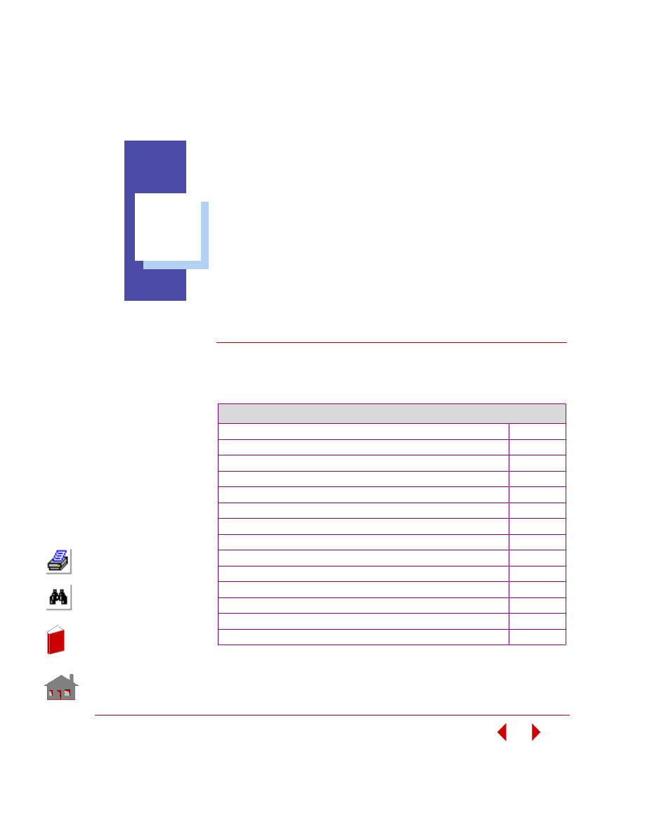
List of Linear Static Verification Problems
S1: Pin JointedTruss
S2: Long Thick-Walled Cylinder
S3A, S3B: Simply Supported Rectangular Plate
S4: Thermal Stress Analysis of a Truss Structure
S5: Thermal Stress Analysis of a 2D Structure
S6A, S6B: Deflection of a Cantilever Beam
S7: Beam Stresses and Deflections
S8: Tip Displacements of a Circular Beam
S9A: Clamped Beam Subject to Imposed Displacement
S9B: Clamped Beam Subject to Imposed Rotation
S10A, S10B: Bending of a Solid Beam
S11: Thermal Stress Analysis of a 3D Structure
S12: Deflection of a Hinged Support
S13: Statically Indeterminate Reaction Force Analysis
In
de
x
In
de
x
Chapter 2 Linear Static Analysis
2-2
COSMOSM Basic FEA System
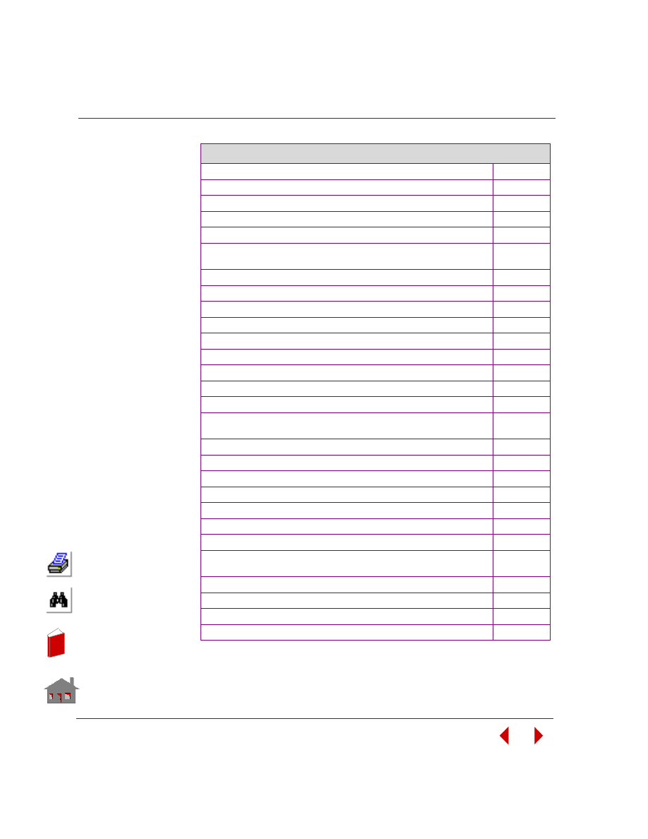
List of Linear Static Verification Problems (Continued)
S14A, S14B: Space Truss with Vertical Load
S15: Out-of-Plane Bending of a Curved Bar
S16A, S16B: Curved Pipe Deflection
S17: Rectangular Plate Under Triangular Thermal Loading
S18: Hemispherical Dome Under Unit Moment Around Free Edge
S19: Hollow Thick-walled Cylinder Subject to Temperature and
Pressure
S20A, S20B: Cylindrical Shell Roof
S21A, S21B: Antisymmetric Cross-Ply Laminated Plate (SHELL4L)
S22: Thermally Loaded Support Structure
S23: Thermal Stress Analysis of a Frame
S24: Thermal Stress Analysis of a Simple Frame
S25: Torsion of a Square Box Beam
S26: Beam With Elastic Supports and a Hinge
S27: Frame Analysis with Combined Loads
S28: Cantilever Unsymmetric Beam
S29A, S29B: Square Angle-Ply Composite Plate Under Sinusoidal
Loading
S30: Effect of Transverse Shear on Maximum Deflection
S31: Square Angle-Ply Composite Plate Under Sinusoidal Loading
S32A, S32B, S32C, S32D, S32M: Substructure of a Tower
S33A, S33M: Substructure of an Airplane (Wing)
S34: Tie Rod with Lateral Loading
S35A, S35B: Spherical Cap Under Uniform Pressure (Solid)
S36A, S36B: Substructure of a Simply Supported Plate
S37: Hyperboloidal Shell Under Uniform Ring Load Around Free
Edge
S38: Rotating Solid Disk
S39: Unbalanced Rotating Flywheel
S40: Truss Structure Subject to a Concentrated Load
S41: Reactions of a Frame Structure
In
de
x
In
de
x
COSMOSM Basic FEA System
2-3
Part 2 Verification Problems
List of Linear Static Verification Problems (Continued)
S42A, S42B: Reactions and Deflections of a Cantilever Beam
S43: Bending of a T Section Beam
S44A, S44B: Bending of a Circular Plate with a Center Hole
S45: Eccentric Frame
S46, S46A, S46B: Bending of a Cantilever Beam
S47, S47A, S47B: Bending of a Cantilever Beam
S48: Rotation of a Tank of Fluid (PLANE2D Fluid)
S49A, S49B: Acceleration of a Tank of Fluid (PLANE2D Fluid)
S50A, S50B, S50C, S50D, S50F, S50G, S50H, S50I: Deflection
of a Curved Beam
S51: Gable Frame with Hinged Supports
S52: Support Reactions for a Beam with Intermediate Forces and
Moments
S53: Beam Analysis with Intermediate Loads
S54: Analysis of a Plane Frame with Beam Loads
S55: Laterally Loaded Tapered Beam
S56: Circular Plate Under a Concentrated Load (SHELL9 Element)
S57: Test of a Pinched Cylinder with Diaphragm (SHELL9 Element)
S58A, S58B, S58C: Deflection of a Twisted Beam with Tip Force
(SHELL9 and TETRA4R Elements)
S59A, S59B, S59C: Sandwich Square Plate Under Uniform
Loading (SHELL9L)
S60: Clamped Square Plate Under Uniform Loading
S61: Single-Edge Cracked Bend Specimen, Evaluation of Stress
Intensity Factor Using Crack Element
S62: Plate with Central Crack
S63: Cyclic Symmetry Analysis of a Hexagonal Frame
S64A, S64B: Cyclic Symmetry
S65: Fluid-Structure Interaction, Rotation of a Tank of Fluid
S66: Fluid-Structure Interaction, Acceleration of a Tank of Fluid
S67: MacNeal-Harder Test
S68: P-Method Solution of a Square Plate with Hole
In
de
x
In
de
x
Chapter 2 Linear Static Analysis
2-4
COSMOSM Basic FEA System
List of Linear Static Verification Problems (Concluded)
S69: P-Method Analysis of an Elliptic Membrane Under Pressure
S70: Thermal Analysis with Temperature Dependent Material
S71: Sandwich Beam with Concentrated Load
S74: Constant Stress Patch Test (TETRA4R)
S75: Analysis of a Cantilever Beam with Gaps, Subject to Different
Loading Conditions
S76: Simply Supported Beam Subject to Pressure from a Rigid
Parabolic Shaped Piston
S77: Bending of a Solid Beam Using Direct Material Matrix Input
S78: P-Adaptive Analysis of a Square Plate with a Circular Hole
S79: Hemispherical Shell Under Unit Moment Around Free Edge
S80: Axisymmetric Hyperbolic Shell Under a Cosine Harmonic
Loading on the Free Edge
S81: Circular Plate Under Non-Axisymmetric Load
S82: Twisting of a Long Solid Shaft
S83: Bending of a Long Solid Shaft
S84: Submodeling of a Plate
S85: Plate on Elastic Foundation
S86: Plate with Coupled Degrees of Freedom
S87: Gravity Loading of ELBOW Element
S88A, S88B: Single-Edge Cracked Bend Specimen, Evaluation
of Stress Intensity Factor Using the J-integral
S89A, S89B: Slant-Edge Cracked Plate, Evaluation of Stress
Intensity Factors Using the J-integral
S90A, S90B: Penny-Shaped Crack in Round Bar, Evaluation of
Stress Intensity Factor Using the J-integral
S91: Crack Under Thermal Stresses, Evaluation of Stress Intensity
Using the J-integral
S92A, S92B: Simply Supported Rectangular Plate, Using Direct
Material Matrix Input
S93: Accelerating Rocket
S94A, S94B, S94C: P-Method Solution of a Square Plate with Small
Hole
S95A, S95B, S95C: P-Method Solution of a U-Shaped
Circumferential Groove in Circular Shaft
In
de
x
In
de
x
COSMOSM Basic FEA System
2-5
Part 2 Verification Problems
S96A, S96B, S96C: P-Method Solution of a Square Plate with an
Elliptical Hole
2-149
In
de
x
In
de
x
Chapter 2 Linear Static Analysis
2-6
COSMOSM Basic FEA System
TYPE:
Static analysis, truss element (TRUSS3D).
REFERENCE:
Beer, F. P., and Johnston, E. R., Jr., “Vector Mechanics for Engineers: Statics and
Dynamics,” McGraw-Hill Book Co., Inc. New York, 1962, p. 47.
PROBLEM:
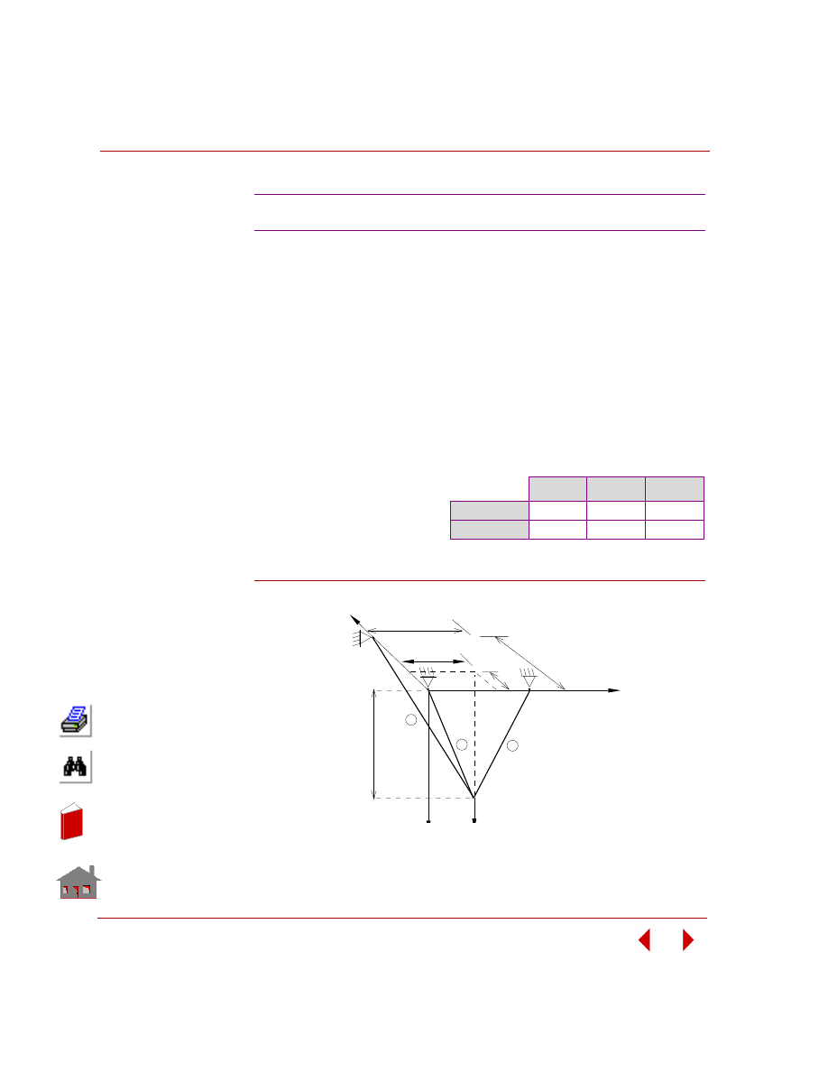
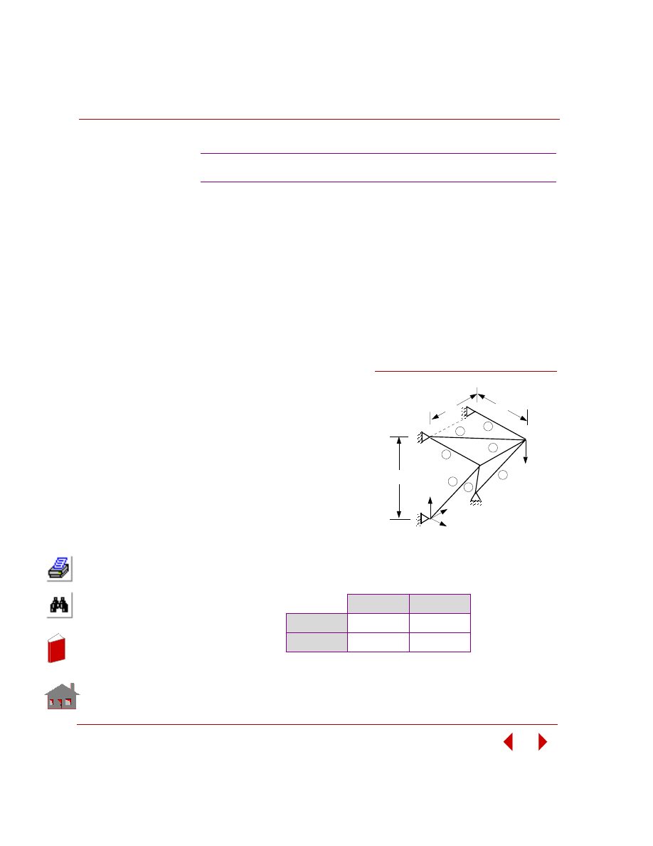
A 50 lb load is supported by three bars which are attached to a ceiling as shown.
Determine the stress in each bar.
:
Figure S1-1
S1: Pin Jointed Truss
GIVEN:
COMPARISON OF RESULTS
Area of each bar = 1 in
2
E = 30 x 10
6
psi
σ
1-4
, psi
σ
2-4
, psi
σ
3-4
, psi
Theory
10.40
31.20
22.90
COSMOSM
10.39
31.18
22.91
x
2
2
6 ft
2 ft
6 ft
8 ft
4 ft
4
1
y
1
3
3
Problem Sketch and
Finite Element Model
In
de
x
In
de
x
COSMOSM Basic FEA System
2-7
Part 2 Verification Problems
TYPE:
Static analysis, 2D axisymmetric elements (PLANE2D).
REFERENCE:
Timoshenko, S. P. and Goodier, J., “Theory of Elasticity,” McGraw-Hill, New York,
1951, pp. 58-60.
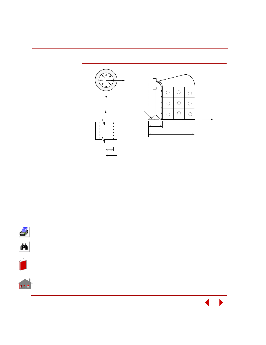
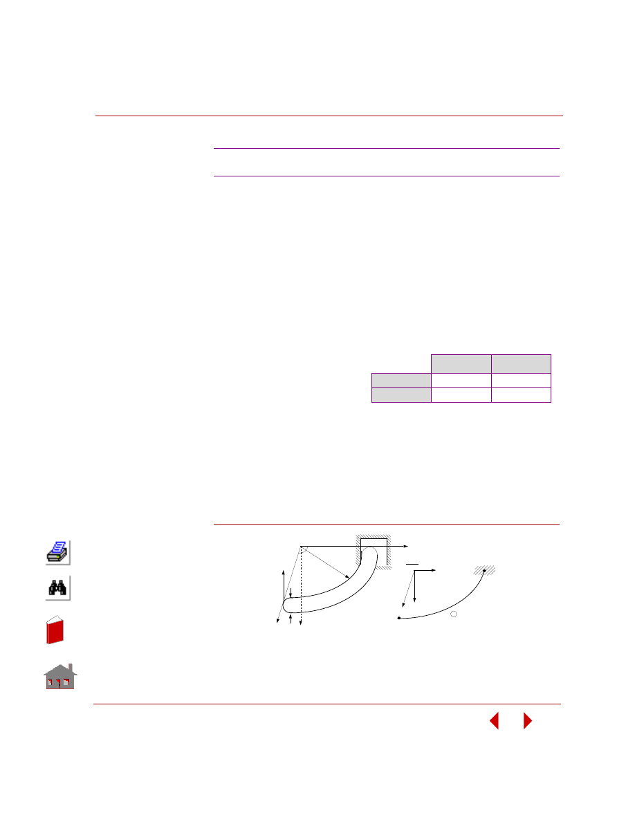
PROBLEM:
Calculate the radial stresses for an infinitely long, thick walled cylinder subjected to
an internal pressure p.
GIVEN:
a
= 100 in
b =
115
in
p =
1000
psi
E = 30 x 10
6
psi
ν =
0.3
MODELING HINTS:
The model is meshed with three elements through the thickness and three elements
along the length.
COMPARISON OF RESULTS:
S2: Long Thick-Walled Cylinder
r (Radial Distance)
(in)
Radial Stress
σ
r
(psi)
Theory
COSMOSM
102.5 (Element 1)
-802.40
-802.51
107.5 (Element 2)
-447.75
-447.84
112.5 (Element 3)
-139.34
-139.42
In
de
x
In
de
x
Chapter 2 Linear Static Analysis
2-8
COSMOSM Basic FEA System
Figure S2-1
a
b
x
σ
r
4
5
6
7
8
9
1
2
3
1
2
3
4
5
6
7
8
9
10
11
12
13
14
15
16
a
b
p
y
1 rad
Finite Element Model
Problem Sketch
x
z
y
p
In
de
x
In
de
x

COSMOSM Basic FEA System
2-9
Part 2 Verification Problems
TYPE:
Static analysis, 3-node thin plate element (SHELL3).
REFERENCE:
Timoshenko, S. P. and Woinowsky-Krieger, “Theory of Plates and Shells,”
McGraw-Hill Book Co., 2nd edition. pp. 143-120, 1962.
PROBLEM:
Calculate the deflection
at the center of a simply
supported isotropic
plate subjected to (A)
concentrated load F, (B)
uniform pressure (P).
GIVEN:
E
= 30,000,000 psi
ν
= 0.3
h
= 1 in
a
= b = 40 in
F
= 400 lb
p
= 1 psi
MODELING HINTS:
Due to double symmetry in geometry and loads, only a quarter of the plate is
modeled.
COMPARISON OF RESULTS:
S3A, S3B: Simply Supported Rectangular Plate
Case
X (in)
Y (in)
Deflection at Node 25 (UZ)
Theory
COSMOSM
A
20
20
-0.0270230 in
-0.027123 in
B
20
20
-0.00378327 in
-0.0037915 in
b
a
Z
Y
X
h
1
Problem Sketch and Finite Element Model
5
21
25
F
Figure S3-1
In
de
x
In
de
x
Chapter 2 Linear Static Analysis
2-10
COSMOSM Basic FEA System
TYPE:
Linear thermal stress analysis, truss elements (TRUSS2D).
REFERENCE:
Hsieh, Y. Y. “Elementary Theory of Structures,” Prentice-Hall, Inc., 1970, pp. 200-
202.
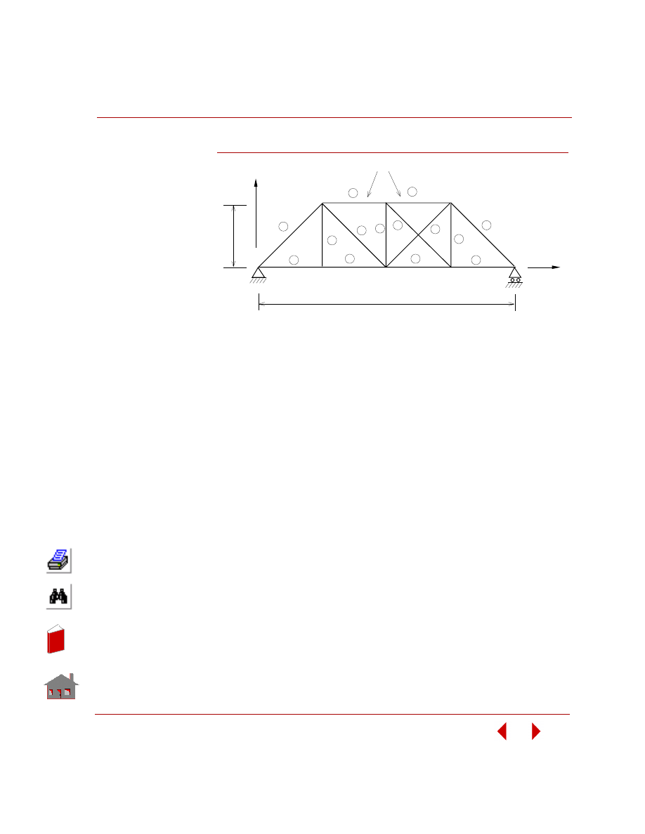
PROBLEM:
Determine the member forces in truss stucture shown in the figure subject to a 50
°
F rise in temperature at the top chords (elements 13 and 14).
GIVEN:
E = 30 x 10
6
psi
Coefficient of thermal expansion =
α = 0.65 x 10
-5
/
°F
L(ft)/A(in
2
) = 1for all members
COMPARISON OF RESULTS:
COSMOSM results are calculated by listing element stress results and multiplying
by the corresponding area.
S4: Thermal Stress Analysis of a Truss Structure
Member Forces (kips
Members
Theory
COSMOSM
Members
Theory
COSMOSM
1
0
0
8
35.1
35.1
2
0
0
9
0
0
3
-21.1
-21.1
10
0
0
4
0
0
11
35.1
35.1
5
0
0
12
0
0
6
-28.1
-28.1
13
0
0
7
-28.1
-28.1
14
-21.1
-21.1
In
de
x
In
de
x
COSMOSM Basic FEA System
2-11
Part 2 Verification Problems
Figure S4-1
14
50
°
F
x
8
6
4
2
7
5
3
1
13
8
11
12
10
1
9
5
3
2
4
7
6
4 x @ 24 ft = 96 ft
32 ft
Y
Problem Sketch and Finite Element Model
In
de
x
In
de
x
Chapter 2 Linear Static Analysis
2-12
COSMOSM Basic FEA System
TYPE:
Linear thermal stress analysis, 2D elements (plane strain, PLANE2D).
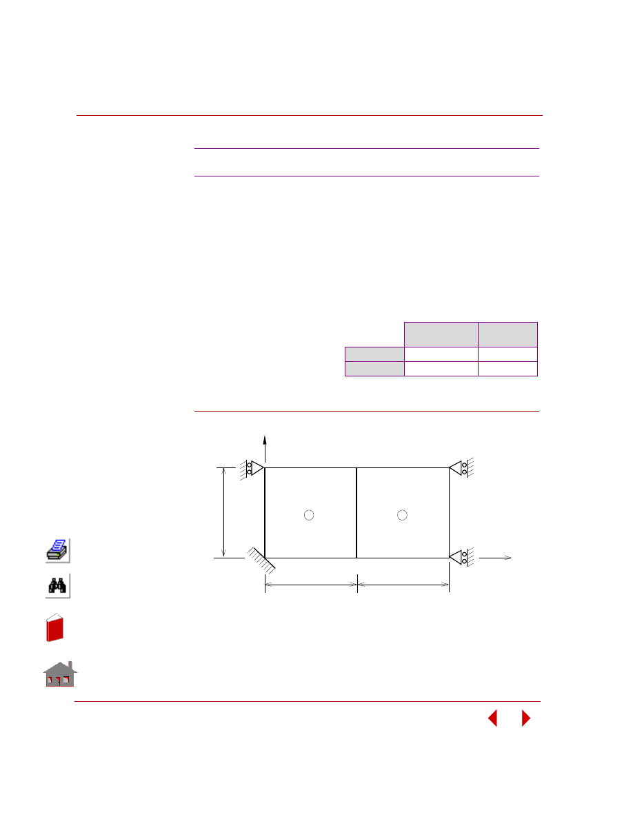
PROBLEM:
Determine the displacements and stresses of the plane strain problem shown in
figure due to a uniform temperature rise.
Figure S5-1
S5: Thermal Stress Analysis of a 2D Structure
GIVEN:
E
= 30 x 10
6
psi
α = 0.65 x 10
-5
/
°F
ν
= 0.25
T
= 100
° F
L
= 1 in
COMPARISON OF RESULTS:
Displacements at Nodes (2, 4, and 6)
Y-Displacement
(in)
SX-Stress
(psi)
Theory
0.001083
-26000.0
COSMOSM
0.001083
-26000.1
1
2
L
y
x
1
2
3
4
5
6
L
L
Problem Sketch and Finite Element Model
In
de
x
In
de
x
COSMOSM Basic FEA System
2-13
Part 2 Verification Problems
TYPE:
Static analysis, plane stress element PLANE2D and SHELL6.
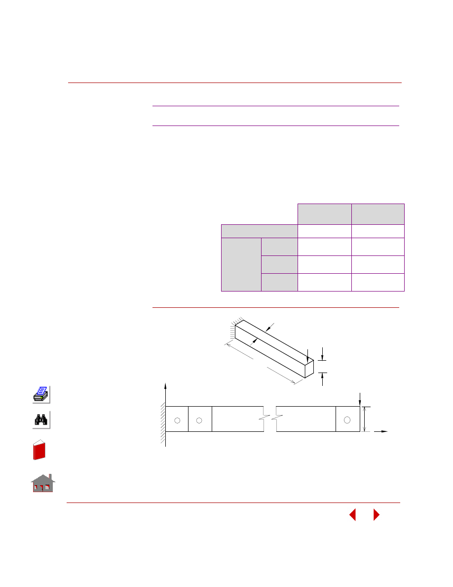
PROBLEM:
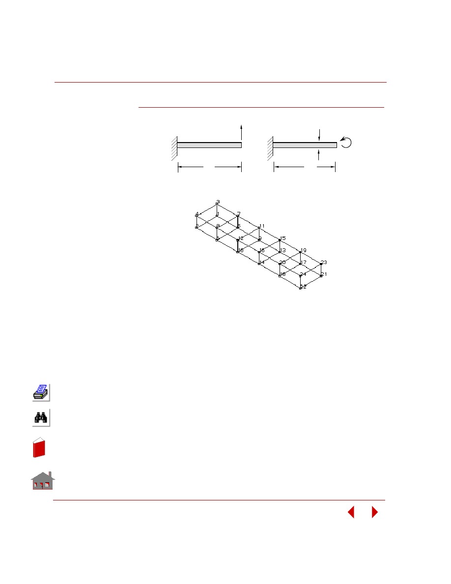
A cantilever beam is subjected to a concentrated load at the free end. Determine the
deflections at the free end and the average shear stress.
Figure S6-1
S6A, S6B: Deflection of a Cantilever Beam
GIVEN:
COMPARISON OF RESULTS:
E
= 30 x 10
6
psi
L
= 10 in
h = 1 in
A = 0.1 in
2
ν
= 0
P
= 1 lb
* averaged results of
nodes at the free edge
Max. Deflection in
the Y-direction
Shear Stress
(psi)
Theory
-0.001333
-10.0
COSMOSM
PLANE2D
-0.001337
-10.0*
SHELL6
(Curved)
-0.0013398
-9.820667*
SHELL6
(Assembled)
-0.00072411
--8.530667*
1
10
2
y
2
4
6
l
3
5
22
21
x
P
h
Finite Element Model
L
t
Problem Sketch
h
P
In
de
x
In
de
x
Chapter 2 Linear Static Analysis
2-14
COSMOSM Basic FEA System
TYPE:
Static analysis, beam elements (BEAM3D).
REFERENCE:
Timoshenko, S. P., “Strength of Materials, Part 1, Elementary Theory and
Problems,” 3rd Ed., D. Van Nostrand Co., Inc., New York, 1965, p. 98.
PROBLEM:
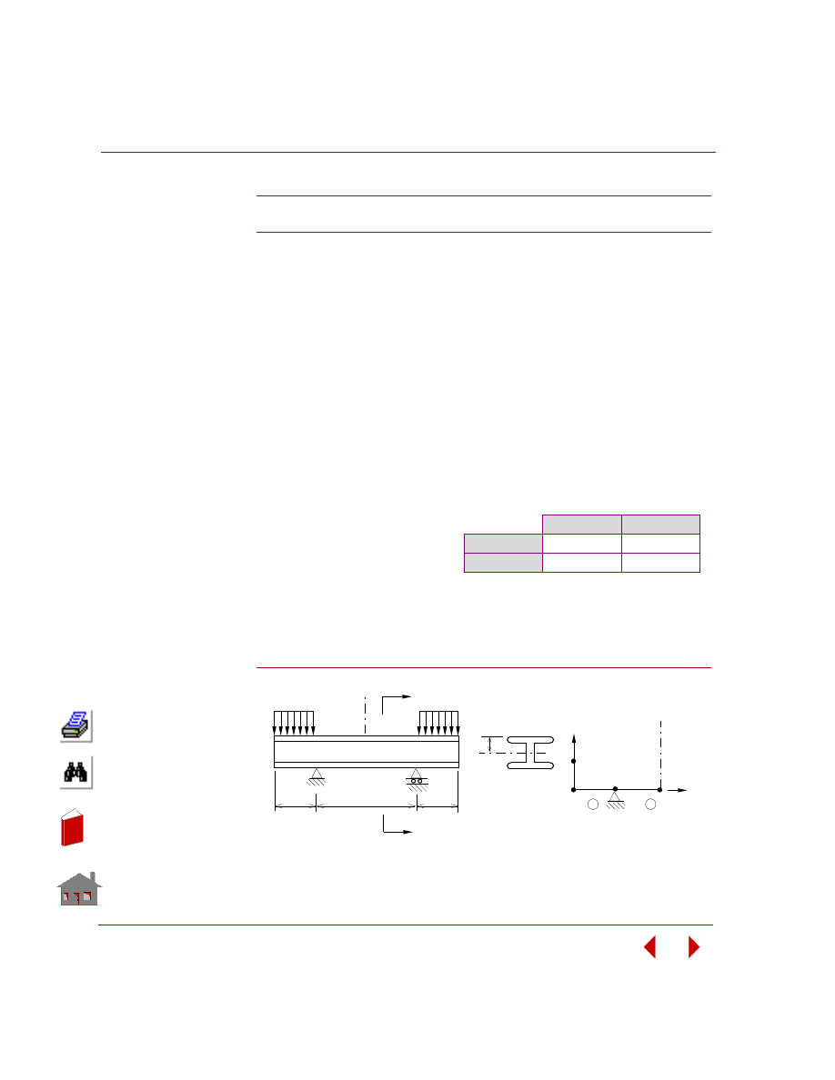
A standard 30" Wide Flange beam is supported as shown below and loaded on the
overhangs by a uniformly distributed load of 10,000 lb per ft. Determine the
maximum stress in the middle portion of the beam and the deflection at the center of
the beam.
MODELING HINTS:
Use consistent length units. A half-model has been used because of symmetry.
Resultant force and moment have been applied at node 2 instead of distributed load.
Figure S7-1
S7: Beam Stresses and Deflections
GIVEN:
Area = 50.65 in
2
E
= 30 x 10
6
psi
p
= 10,000 lb/ft
COMPARISON OF RESULTS:
At the middle of the span (node 3):
σ
max
psi
δ
inch
Theory
11400.0
0.182
COSMOSM
11400.0
0.182
Finite Element Model
z
15"
Section a-a
10'
10'
20'
CL
a
Problem Sketch
a
P
P
C
2
1
x
3
2
L
4
y
1
In
de
x
In
de
x
COSMOSM Basic FEA System
2-15
Part 2 Verification Problems
TYPE:
Static analysis, thin or thick shell element (SHELL3).
REFERENCE
Warren C. Young, “Roark's Formulas for Stress and Strain,” Sixth Edition, McGraw
Hill Book Company, New York, 1989.
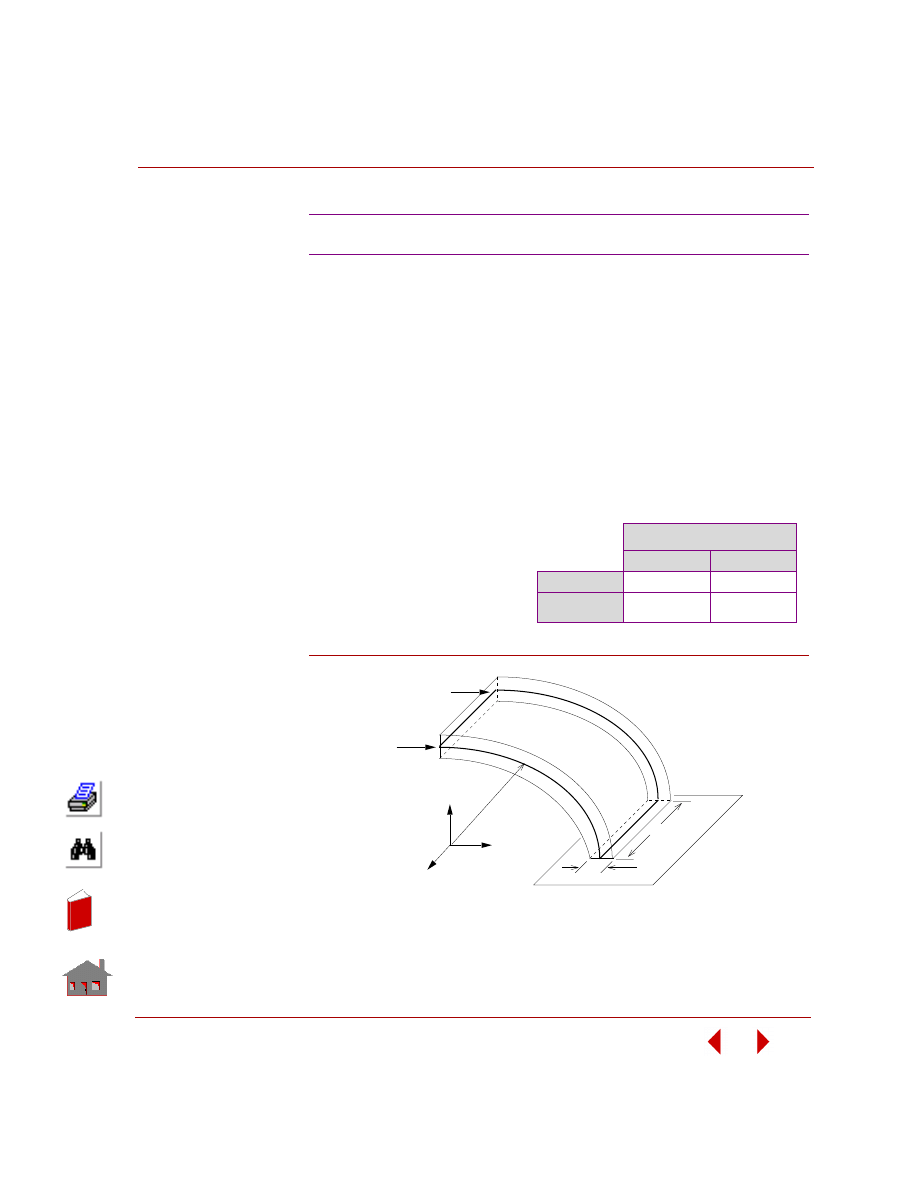
PROBLEM:
Determine the deflections in X, Y direction of a circular beam fixed at one end and
free at the other end, when subjected to a force along X direction at force end.
Figure S8-1
S8: Tip Displacements of a Circular Beam
GIVEN:
E
= 30E6 psi
ν
= 0
b
= 4 in
h
= 1 in
R
= 10 in
F
= 200 lb
COMPARISON OF RESULTS:
The loaded end.
Displacement (inch)
X
Y
Theory
0.712E-2
0.99E-2
COSMOSM
0.718E-2
0.99E-2
F/2
F/2
y
z
x
h
b
R
Problem Sketch and Finite Element Model
In
de
x
In
de
x
Chapter 2 Linear Static Analysis
2-16
COSMOSM Basic FEA System
TYPE:
Static analysis, beam elements (BEAM2D).
REFERENCE
Gere, J. M. and Weaver, W. Jr., “Analysis of Framed Structures,” D. Van Nostrand
Co., 1965.
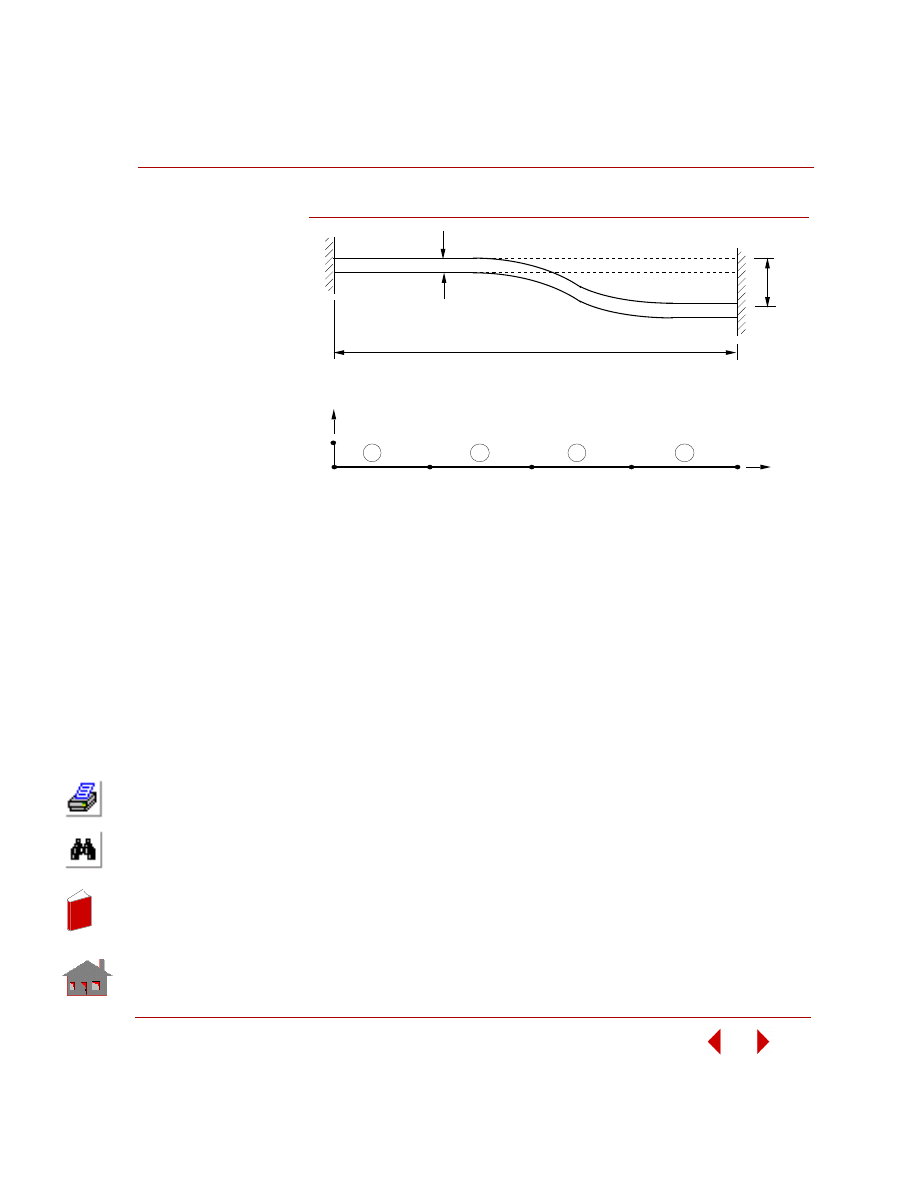
PROBLEM:
Determine the end forces of a clamped beam due to a 1 inch settlement at the right
end.
GIVEN:
E
= 30 x 10
6
psi
l
= 80 in
A = 4 in
2
I
= 1.33 in
4
h
= 2 in
ANALYTICAL SOLUTION:
Reaction: R = -12EI / L
3
Moment: M = 6EI / L
2
COMPARISON OF RESULTS:
S9A: Clamped Beam Subject
to Imposed Displacement
Theory
COSMOSM
Imposed Displacement (in)
-1.0
-1.0
End Shear (lb)
-937.5
-937.5
End Moment (lb-in)
-37,500.0
-37,500.0
In
de
x
In
de
x
COSMOSM Basic FEA System
2-17
Part 2 Verification Problems
Figure S9A-1
1
2
3
4
5
1.0 in
h
6
x
y
4
3
2
1
Problem Sketch
Finite Element Model
L
In
de
x
In
de
x
Chapter 2 Linear Static Analysis
2-18
COSMOSM Basic FEA System
TYPE:
Static analysis, beam elements (BEAM2D).
REFERENCE:
Gere, J. M. N. and Weaver, W. Jr., “Analysis of Framed Structures,” D. Van Nostrand
Co., 1965.
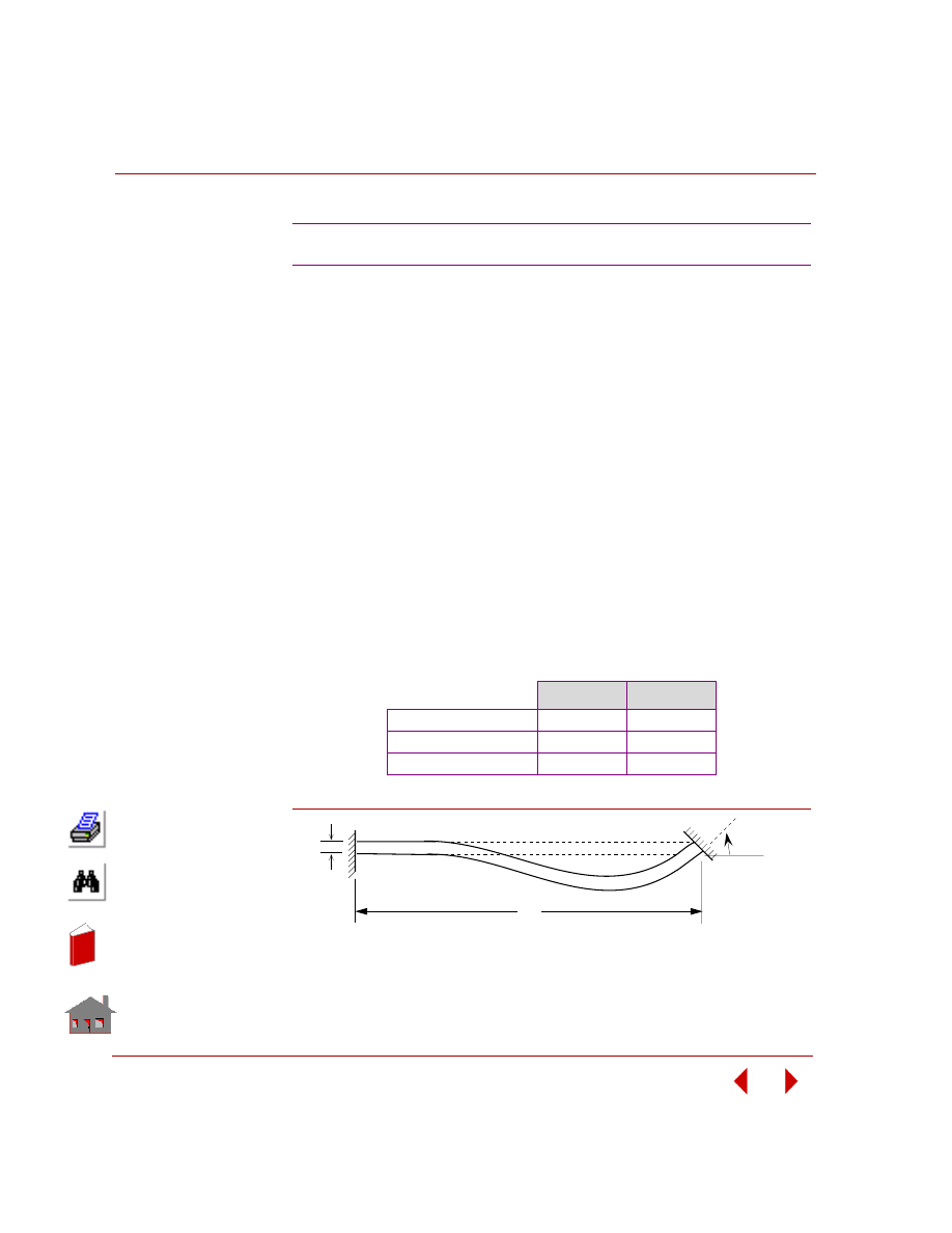
PROBLEM:
Determine the end forces of a clamped-clamped beam due to a 1 radian imposed
rotation at the right end.
COMPARISON OF RESULTS:
Figure S9B-1
S9B: Clamped Beam Subject to Imposed Rotation
GIVEN:
E
= 30 x 10
6
psi
l
= 80 in
A = 4 in
2
I
= 1.3333 in
4
h
= 2 in
ANALYTICAL SOLUTION:
Reaction: R = -6EI / L
2
Moment: M = 4EI / L
Theory
COSMOSM
Imposed Rotation (1 rad)
1
1
End Shear
-37,500
-37,500
End Moment
-2,000,000
-2,000,000
φ
= 1 rad
2
L
h
Problem Sketch
In
de
x
In
de
x
COSMOSM Basic FEA System
2-19
Part 2 Verification Problems
TYPE:
Static analysis, SOLID element.
REFERENCE:
Roark, R. J., “Formulas for Stress and Strain,” 4th Edition, McGraw-Hill Book Co.,
New York, 1965, pp. 104-106.
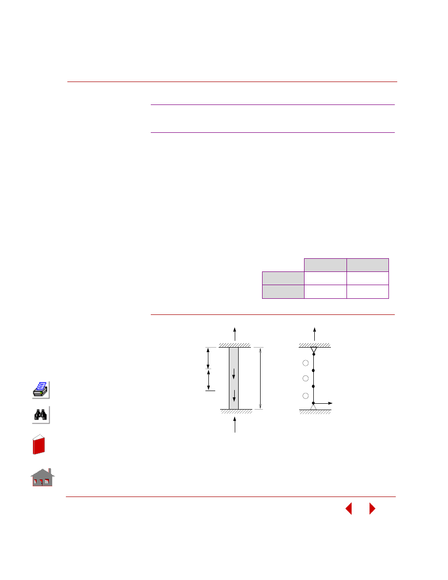
PROBLEM:
A beam of length L and height h is built-in at one end and loaded at free end: (A)
with a shear force F, and (B) a moment M. Determine the deflection at the free end.
GIVEN:
L
= 10 in
h
= 2 in
E
= 30 x 10
6
psi
ν
= 0
F
= 300 lb
M = 2000 in-lb
MODELING HINTS:
Two load cases have been used (S10A, S10B).
1.
Four forces equal to F/4 have been applied at nodes 21, 22, 23, and 24 in xz
direction (S10A), and,
2.
Two couples equal M/2 have been applied at nodes 21, 22, 23 and 24 (S10B).
COMPARISON OF RESULTS:
Displacement in Z-direction (in) (node 21-24):
S10A, S10B: Bending of a Solid Beam
S10A
S10B
Theory
0.00500
-0.00500
COSMOSM
0.005007
-0.00495
In
de
x
In
de
x
Chapter 2 Linear Static Analysis
2-20
COSMOSM Basic FEA System
Figure S10A-1
F
L
h
M
L
Case 1
Case 2
Problem Sketch
Finite Element Model
In
de
x
In
de
x
COSMOSM Basic FEA System
2-21
Part 2 Verification Problems
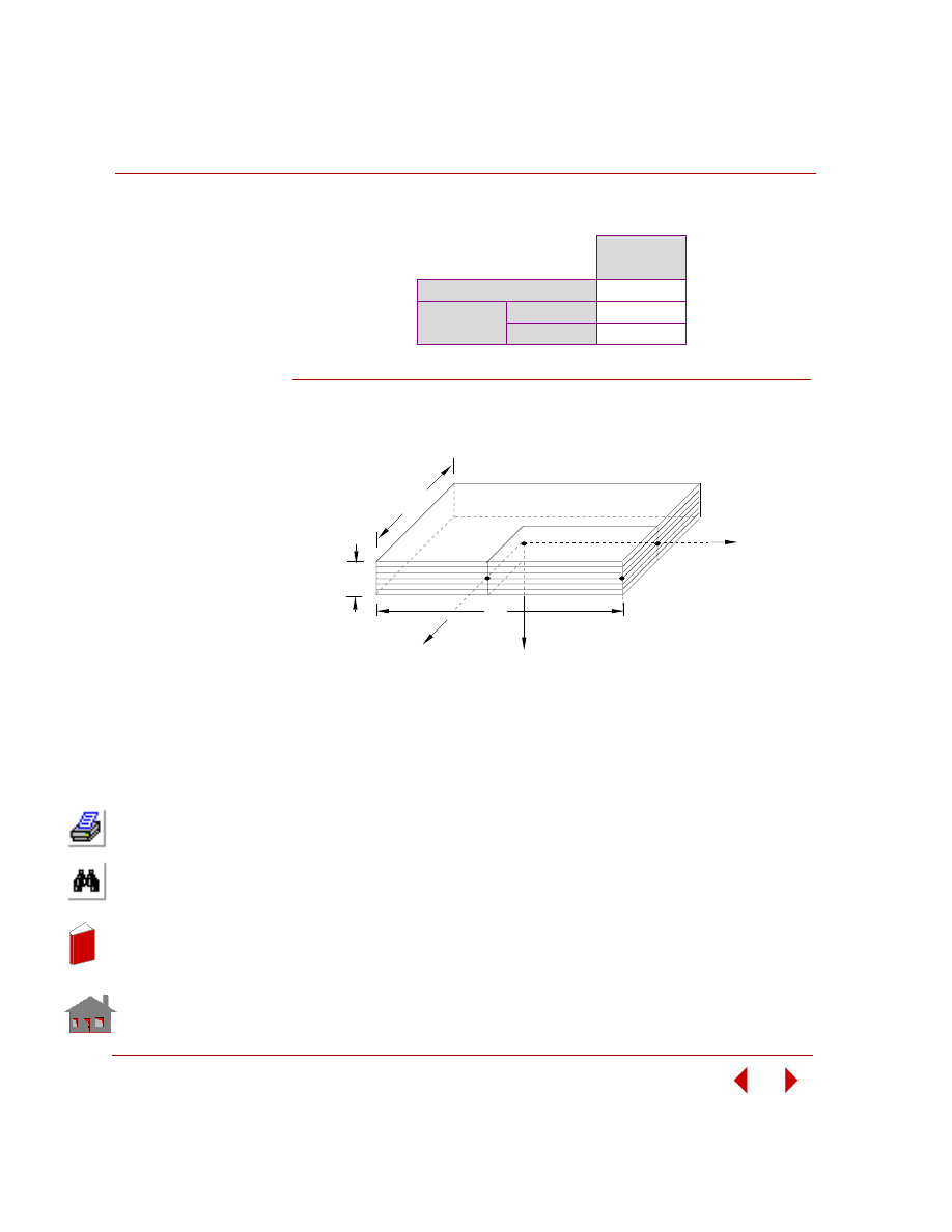
TYPE:
Linear thermal stress analysis, 3D SOLID element.
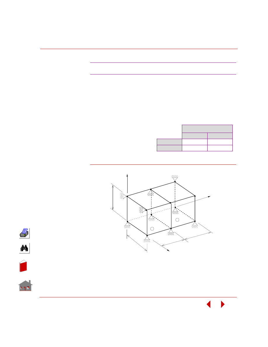
PROBLEM:
Determine the displacements of the three-dimensional structure shown below due to
a uniform temperature rise.
Figure S11-1
S11: Thermal Stress Analysis of a 3D Structure
GIVEN:
COMPARISON OF RESULTS:
E = 3 x 10
7
psi
α = 0.65 x 10
-5
/
°F
ν
= 0.25
T =
100
° F
L
= 1 in
X-Displacement (Nodes)
5, 6, 7, 8
9, 10, 11, 12
Theory
0.000650
0.001300
COSMOSM
0.000650
0.001300
5
8
9
2
1
L
L
L
L
1
2
3
4
6
7
10
11
12
x,r
z,t
y,s
Problem Sketch and Finite Element Model
In
de
x
In
de
x
Chapter 2 Linear Static Analysis
2-22
COSMOSM Basic FEA System
TYPE:
Static analysis, truss element (TRUSS3D).
REFERENCE:
Timoshenko, S. P., and MacCullough, Glesson, H., “Elements of Strength of
Materials,” D. Van Nostrand Co., Inc., 3rd edition, June 1949, p. 13.
PROBLEM:
A structure consisting of two equal steel bars, 15 feet long and with hinged ends, is
submitted to the action of a vertical load P. Determine the forces in the members AB
and BC along with the vertical deflection at B.
Figure S12-1
S12: Deflection of a Hinged Support
GIVEN:
P
= 5000 lbs
θ = 30°
AB = BC = 15 ft
E
= 30 x 10
6
psi
Cross-sectional area
= 0.5 in
2
COMPARISON OF RESULTS:
Theory
COSMOSM
Vertical Deflection at
B in inches
0.12
0.12
Forces in Members
AB and BC in lbs
5000
5000
Y
3
C
2
1
B
P
2
Z
1
θ
θ
A
Problem Sketch and Finite Element Model
In
de
x
In
de
x
COSMOSM Basic FEA System
2-23
Part 2 Verification Problems
TYPE:
Static analysis, truss elements (TRUSS3D).
REFERENCE:
Timoshenko, S. P., “Strength of Materials, Part 1, Elementary Theory and
Problems,” 3rd edition, D. Van Nostrand Co., Inc., 1956, p. 26.
PROBLEM:
A prismatic bar with built-in ends is loaded axially at two intermediate cross-
sections by forces F1 and F2. Determine the reaction forces R1 and R2.
Figure S13-1
S13: Statically Indeterminate
Reaction Force Analysis
GIVEN:
COMPARISON OF RESULTS:
a
= b = 0.3 L
L =
10
in
F
1
= 2F
2
= 1000 lb
E = 30 x 10
6
psi
R
1
lbs
R
2
lbs
Theory
900
600
COSMOSM
900
600
Y
X
1
2
3
4
3
2
1
Finite Element Model
F
F
a
b
R
L
1
1
2
Problem Sketch
R2
In
de
x
In
de
x
Chapter 2 Linear Static Analysis
2-24
COSMOSM Basic FEA System
TYPE:
Static analysis, truss elements (TRUSS3D).
REFERENCE:
Timoshenko, S. P. and Young, D. H. “Theory of Structures,” end Ed., McGraw-Hill,
New York, 1965, pp. 330-331.
PROBLEM:
The simple space truss shown in the figure below consists of two panels ABCD and
ABEF, attached to a vertical wall at points C, D, E, F, the panel ABCD being in a
horizontal plane. All bars have the same cross-sectional area, A, and the same
modulus of elasticity, E.
Calculate:
1.
The axial force produced in the
redundant bar AD by the vertical
load P = 1 kip at joint A (S14A).
2.
The thermal force induced in the
bar AD if there is a uniform rise
in temperature of 50
° F (S14B).
GIVEN:
E = 30 x 10
6
psi
α
= 6.5 x 10
-6
/
°F
A =
1in
2
L = 4 ft
COMPARISON OF RESULTS:
For Element 2:
S14A, S14B: Space Truss with Vertical Load
S14A
S14B
Theory
56.0 lb
-1259.0 lb
COSMOSM
55.92 lb
-1292.4 lb
Figure S14-1
E
6
x
y
z
4
L
1
A
5
4
1
2
3
6
5
7
P
Problem Sketch and Finite
Element Model
2
F
D
C
3
L
L
In
de
x
In
de
x
COSMOSM Basic FEA System
2-25
Part 2 Verification Problems
TYPE:
Static analysis, curved elbow element (ELBOW).
REFERENCE:
Timoshenko, S. P., “Strength of Materials, Part 1, Advanced Theory and Problems,”
3rd Edition, D. Van Nostrand Company, Inc., New York, 1956, p. 412.
PROBLEM:
A portion of a horizontal circular ring, built-in at A, is loaded by a vertical load P
applied at the end B. The ring has a solid circular cross-section of diameter d.
Determine the deflection at end B, and the maximum bending stress.
MODELING HINTS:
COSMOSM does not yet have a curved beam element, although this element will be
incorporated into the program shortly. Hence, the curved elbow element is used to
model this problem. Therefore, it is necessary to use equivalent thickness t which is
equal to the radius of the solid rod.
Figure S15-1
S15: Out-of-Plane Bending of a Curved Bar
GIVEN:
COMPARISON OF RESULTS
P =
50
lb
r =
100
in
d = 2 in
E = 30 x 10
6
psi
α = 90°
ν
= 0.3
δ
z
, inch
σ
Bend
, psi
Theory
-2.648
6366.0
COSMOSM
-2.650
6366.2
z
d
y
B
p
r
α
A
x
x
3
z
y
2
1
1
Problem Sketch
Finite Element Model
In
de
x
In
de
x

Chapter 2 Linear Static Analysis
2-26
COSMOSM Basic FEA System
TYPE:
Static analysis, elbow element (ELBOW).
REFERENCE:
Blake, A., “Design of Curved Members for Machines,” Industrial Press, New York,
1966.
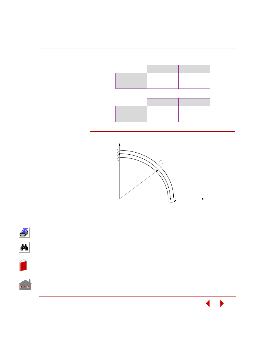
PROBLEM:
Calculate deflections x and y for a curved pipe shown in the figure subjected to:
1.
Moment Mz = 3 x 10
6
lb-in and internal pressure p = 900 psi (S16A).
2.
Internal pressure p = 900 psi (S16B).
GIVEN:
E = 30 x 10
6
psi
ν
=
0.3
R =
72
in
Thickness = 1.031 in
Outer diameter of pipe = 20 in
COMPARISON OF RESULTS:
Blake gives the following results for a 90 curved member. These results do not
include the effects of distortion of the cross-section and internal pressure.
δy = M
z
R
2
/EI = 0.187039 in
δy = M
z
R
2
/EI (P/2-1) = 0.106761 in
The pipe flexibility factor is given by
K
p
= 1.65/h{1 + 6P/Eh) (R/t)
4/3
}, where h = tR/r
2
for p = 900 psi, K
p
= 1.8814761
To obtain the nodal deflections for case l, the deflections calculated by Blake's
formulas must be multiplied by kp and added to the deflections produced by the
internal pressure.
S16A, S16B: Curved Pipe Deflection
In
de
x
In
de
x
COSMOSM Basic FEA System
2-27
Part 2 Verification Problems
S16A
S16B
Figure S16A-1
δ
x
, inch
δ
y
, inch
Theory
0.37035
0.20515
COSMOSM
0.37034
0.20515
δ
x
, inch
δ
y
, inch
Theory
1.84356 x 10
-2
4.2873 x 10
-3
COSMOSM
1.84355 x 10
-2
4.28043 x 10
-3
2
x
M z
1
R
3
y
R = Constant
Problem Sketch and Finite Element Model
1
In
de
x
In
de
x
Chapter 2 Linear Static Analysis
2-28
COSMOSM Basic FEA System
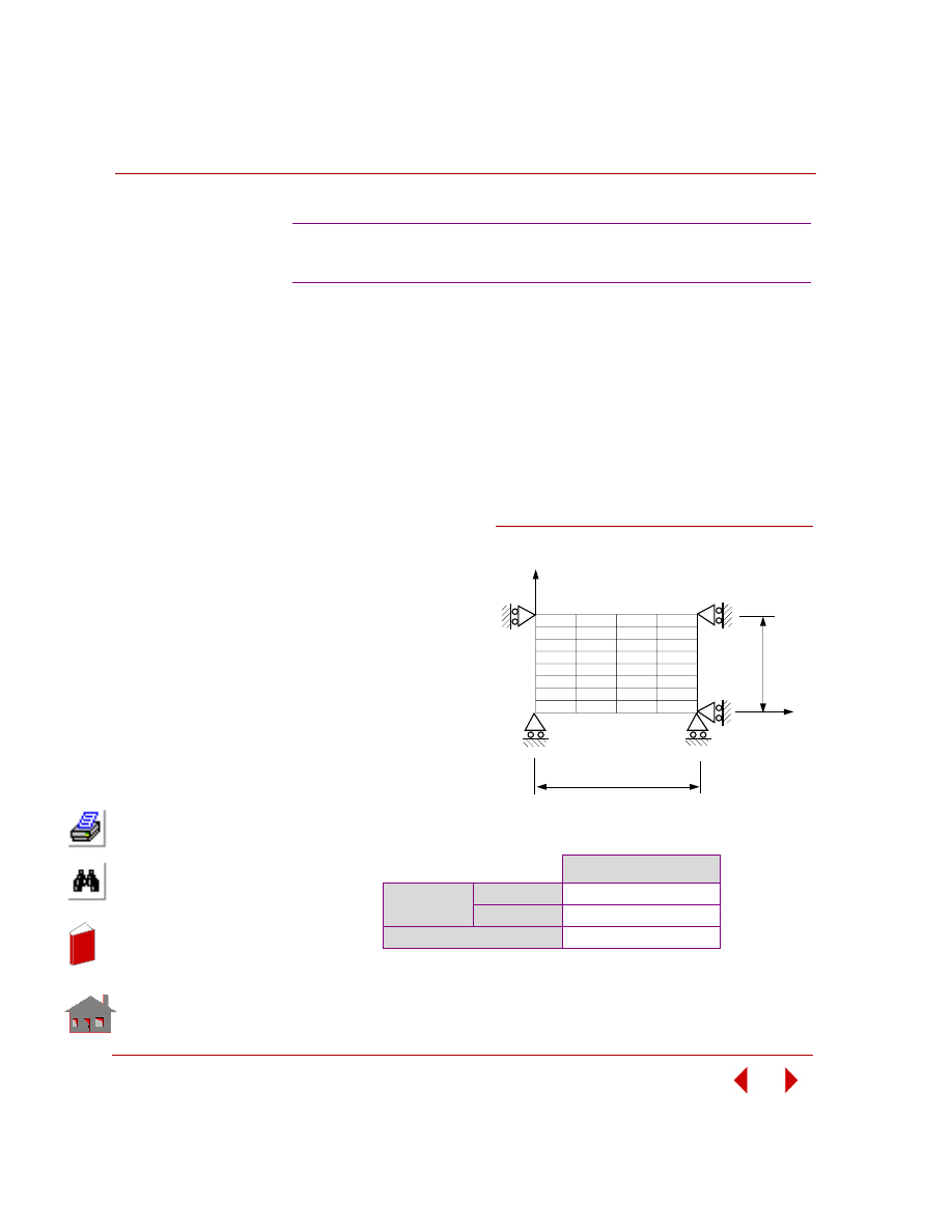
TYPE:
Linear thermal stress analysis, 2D elements (plane stress analysis, PLANE2D).
REFERENCE:
Johns, D. J., “Thermal Stress Analysis,” Pergamon Press, Inc., 1965, pp. 40-47.
PROBLEM:
A finite rectangular plate is subjected to a temperature distribution in only one
direction as shown in figure. Determine the normal stress at point A.
GIVEN:
a
= 15 in
b
= 10 in
T
o
= -100
°F
t
= 1 in
E
= 30 x 10
6
psi
α
c
= 0.65 x 10
-5
in/in/
°F
MODELING HINTS:
Due to the double
symmetry in geometry and
loading, only one quarter
of the plate was analyzed.
COMPARISON OF RESULTS:
S17: Rectangular Plate Under
Triangular Thermal Loading
σ
xx
/ (E
α
T
o
) (Node 45)
Reference
Method 1
0.42
Method 2
0.40
COSMOSM
0.437
Same Boundary Condition
S
a
m
e
B
ounda
ry
C
ondi
ti
on
x
A
y
Figure S17-1
In
de
x
In
de
x
COSMOSM Basic FEA System
2-29
Part 2 Verification Problems
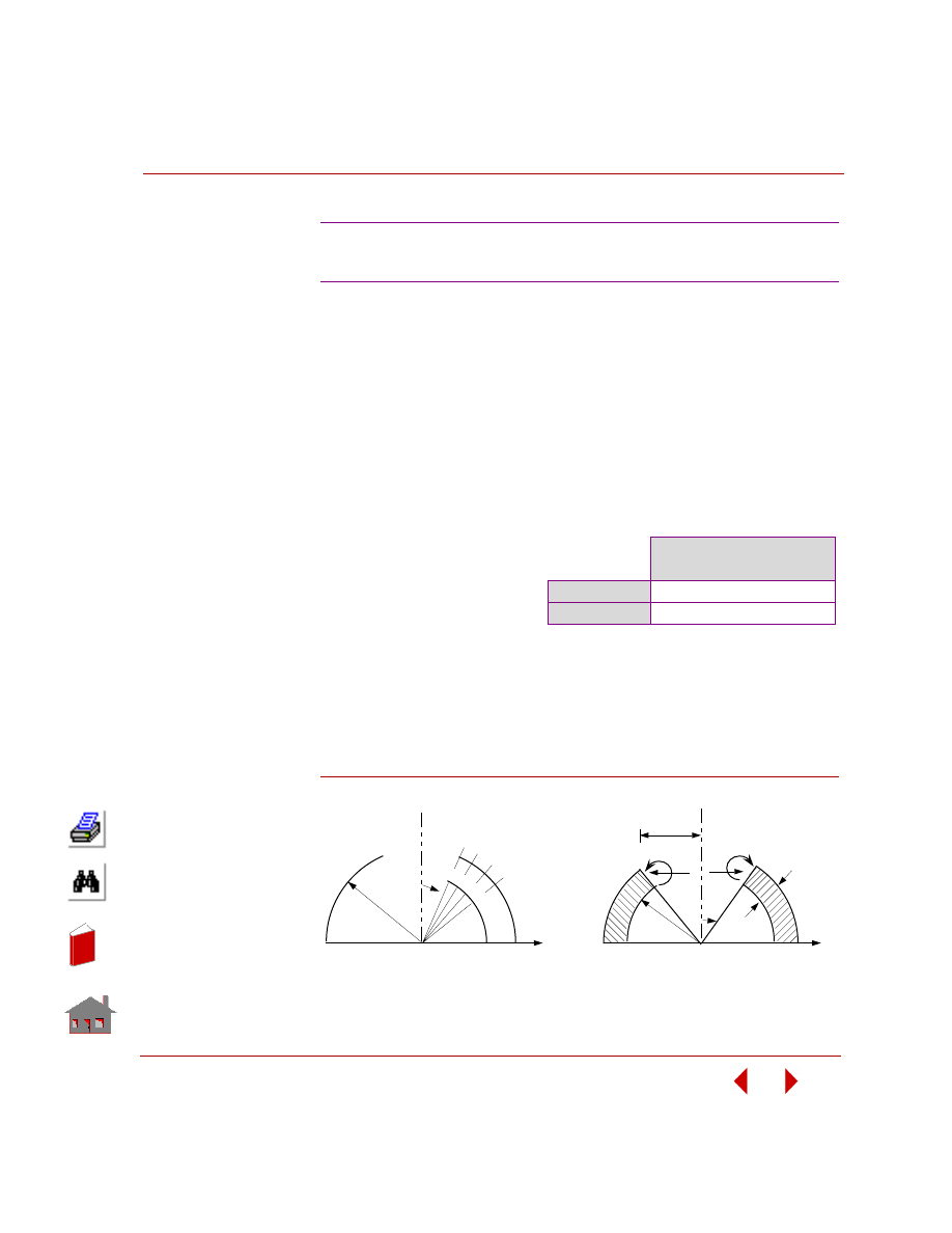
TYPE:
Static linear analysis, axisymmetric shell element (SHELLAX).
REFERENCE:
Zienkiewicz, O. C. “The Finite Element Method,” Third edition, McGraw-Hill Book
Co., New York, 1983, p. 362.
PROBLEM:
Determine the horizontal displacement of a hemispherical shell under uniform unit
moment around the free edge.
MODELING HINTS:
Nodal spacing is shown in the Figure. For convenience, cylindrical coordinate
system is chosen for node generation. It is important to note that nodal load is to be
specified per unit radian which in this case is 50 in lb/rad.
Figure S18-1
S18: Hemispherical Dome Under
Unit Moment Around Free Edge
GIVEN:
R
= 100 in
r
= 50 in
E = 1 x 10
7
psi
ν =
0.33
t =
1
in
M = 1 in lb
COMPARISON OF RESULTS:
Horizontal Displacement
(Node 29) (inch)
Reference
1.580 E-5
COSMOSM
1.589 E-5
θ
Nodal Spacing
14 @ 0.5
°
interval
7 @ 0.5
°
interval
3 @ 2.0
°
interval
4 @ 10.0
°
interval
5
Finite Element Model
y
H
H
R
30
r
Problem Sketch
t
y
x
x
M
M
r
In
de
x
In
de
x
Chapter 2 Linear Static Analysis
2-30
COSMOSM Basic FEA System
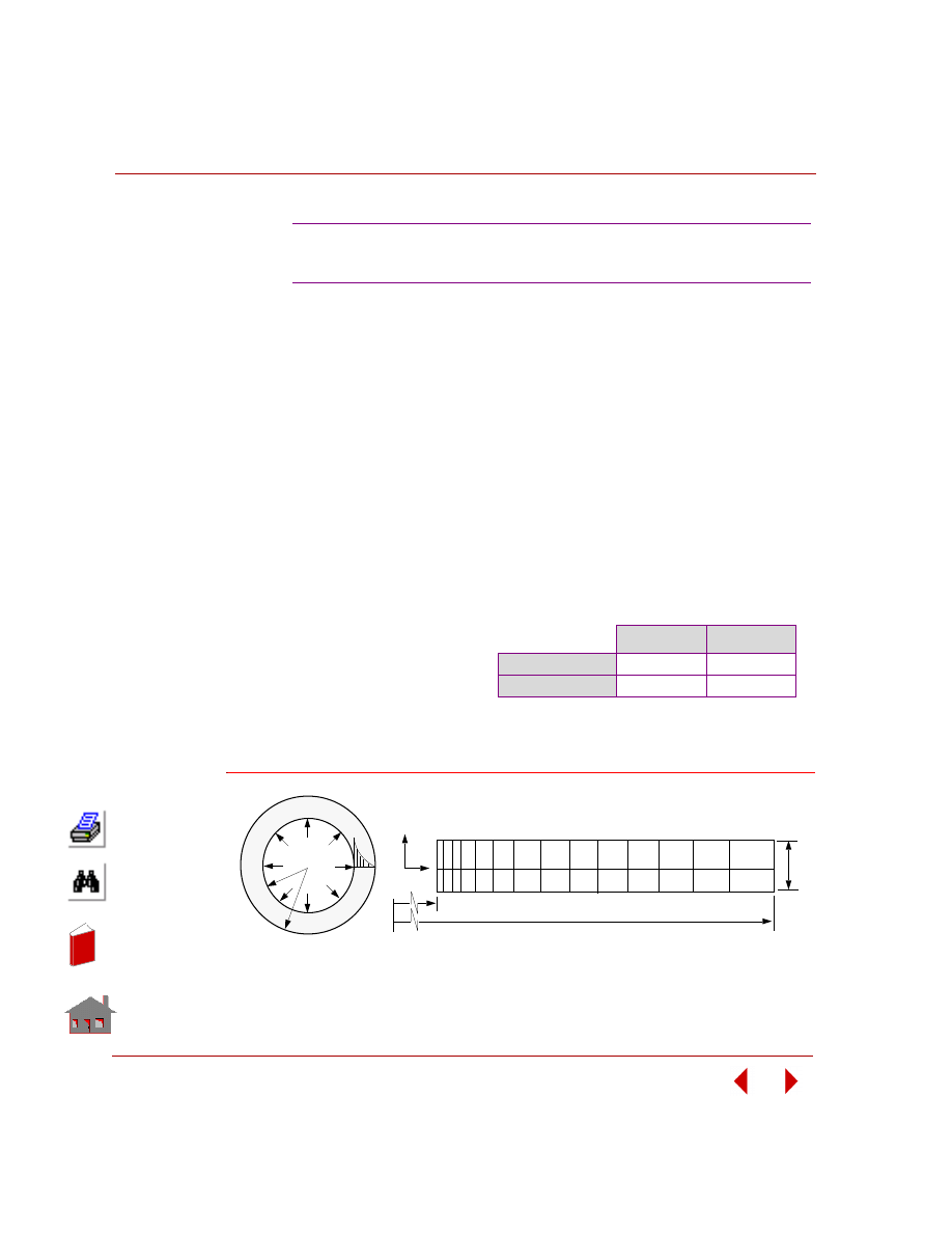
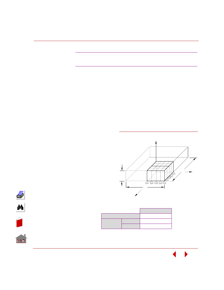
TYPE:
Static analysis, 2D axisymmetric element (PLANE2D).
REFERENCE:
Timoshenko, S. P. and Goodier, “Theory of Elasticity,” McGraw-Hill Book Co.,
New York, 1961, pp. 448-449.
PROBLEM:
The hollow cylinder in plane strain is subjected to two independent load conditions.
1.
An internal pressure.
2.
A steady state axisymmetric temperature distribution given by the equation:
T(r) = (Ta/ln(b/a)) · ln(b/r) where Ta is the temperature of the inner surface
and T(r) is the temperature at any radius.
S19: Hollow Thick-walled Cylinder Subject
to Temperature and Pressure
GIVEN:
E = 30 x 10
6
psi
a
= 1 in
b = 2 in
ν =
0.3
α = 1 x 10
-6
in/(in
°F)
Pa = 100 psi
Ta =
100
°F
COMPARISON OF RESULTS:
At r = 1.2875 in (elements 13, 15)
σ
r
, psi
σ
θ, psi
Theory)
-398.34
-592.47
COSMOSM
-398.15
-596.46
Figure S19-1
a
T(r)
Pa
x
y
b
0.1
Problem Sketch
Finite Element Model
a
b
Ta
In
de
x
In
de
x
COSMOSM Basic FEA System
2-31
Part 2 Verification Problems
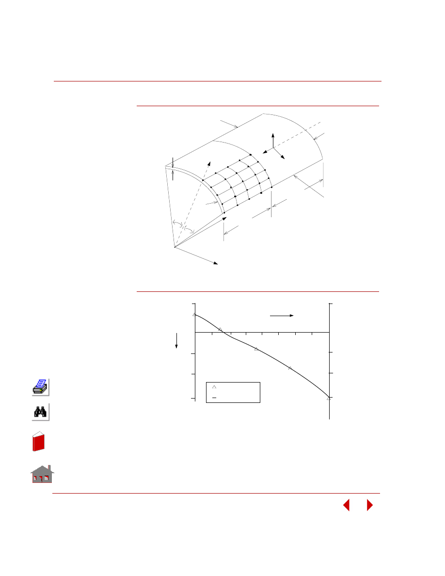
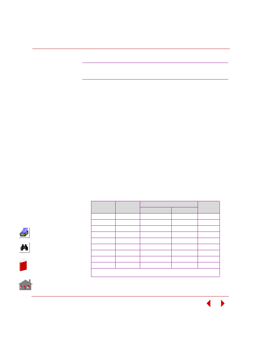
TYPE:
Static analysis, shell element (SHELL4, SHELL6).
REFERENCE:
Pawsley, S. F., “The Analysis of Moderately Thick to Thin Shells by the Finite
Element Method,” Report No. USCEM 70-l2, Dept. of Civil Engineering,
University of California, l970.
PROBLEM:
Determine the vertical deflections across the midspan of a shell roof under its own
weight. Dimensions and boundary conditions are shown in the figure below.
GIVEN:
r =
25
ft
E
= 3 x 10
6
psi
ν =
0
Shell Weight = 90 lbs/sq ft
MODELING HINTS:
Due to symmetry, a quarter of the shell is considered for modeling. The distributed
force (self weight) is lumped at the nodes.
COMPARISON OF RESULTS:
Vertical Deflection at Midspan of free edge (Node 25):
S20A, S20B: Cylindrical Shell Roof
δ
x
, (inch)
Theory
-0.3024
COSMOSM
SHELL4
-0.3036
SHELL6
(Curved)
-0.24580
SHELL6
(Assembled)
-0.29353
In
de
x
In
de
x
Chapter 2 Linear Static Analysis
2-32
COSMOSM Basic FEA System
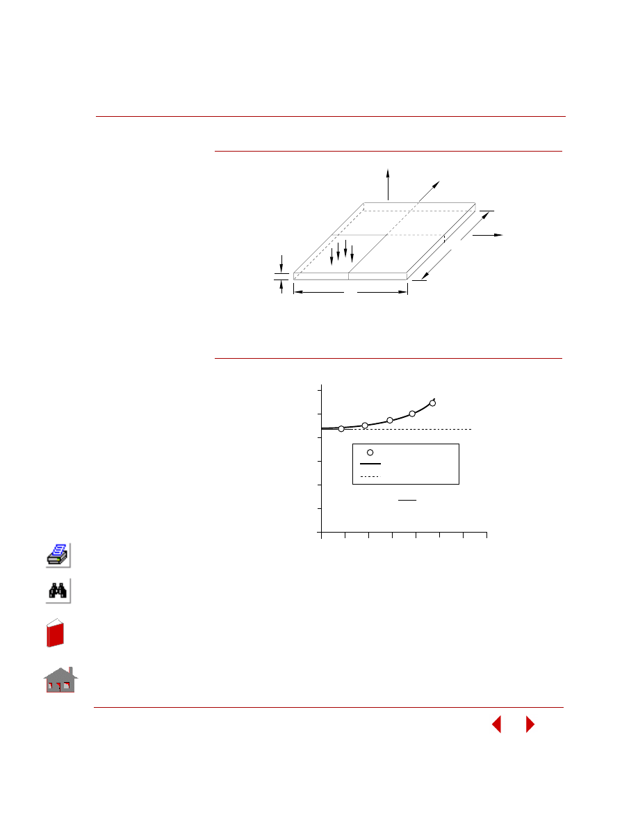
Figure S20-1
Figure S20-2
25 ft
25 ft
Free Edge
Free Edge
v =
w = 0
t = 0.25 ft
v = w = 0
40
°
40
°
Y
Z
U
V
W
1
5
21
25
X
Problem Sketch and Finite
Element Model
r
0.18961
0.30365
-.2
0.07423
0.01335
0.004676
-.1
-.3
.1
.1
-.1
-.2
-.3
W
θ
COSMOS/M
EXACT
0
5
10 15
20
25
30
35
40
In
de
x
In
de
x

COSMOSM Basic FEA System
2-33
Part 2 Verification Problems
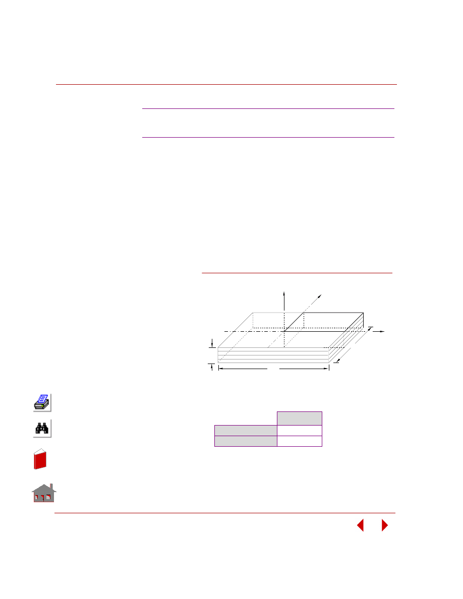
TYPE:
Static analysis, composite shell element (SHELL4L, SHELL9L).
REFERENCE:
Jones, Robert M., “Mechanics of Composite Materials,” McGraw-Hill, New York,
l975, p. 256.
PROBLEM:
Calculate the maximum deflection of a simply supported antisymmetric cross-ply
laminated plate under sinusoidal load. The plate is made up of 6-layers and the
material in each layer is orthotropic.
GIVEN:
a =
l00
in
b =
20
in
h = l in
E
a
= 40E6 psi
E
b
= lE6 psi
ν
ab
= 0.25
G
ab
= G
ac
= G
bc
= 5E5 psi
For each layer, pressure loading = cos
π x/a · cos π y/b
MODELING HINT:
Due to symmetry, a quarter of the plate is considered for modeling.
S21A, S21B: Antisymmetric Cross-Ply
Laminated Plate (SHELL4L)
In
de
x
In
de
x
Chapter 2 Linear Static Analysis
2-34
COSMOSM Basic FEA System
COMPARISON OF RESULTS:
Figure S21-1
Maximum
Deflection (in)
Theory
0.105E-2
COSMOSM
4-nod shell
0.104E-2
9-node shell
0.111E-2
Y
X
h
a
1
5
Problem Sketch and Finite Element Model
b
21
25
Z
In
de
x
In
de
x
COSMOSM Basic FEA System
2-35
Part 2 Verification Problems
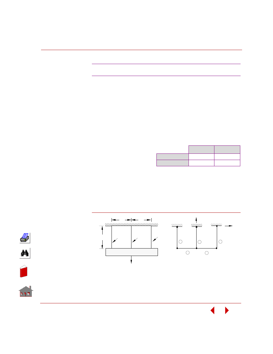
TYPE:
Static, thermal stress analysis, truss and beam elements (TRUSS3D, BEAM3D).
REFERENCE:
Timoshenko, S. P., “Strength of Materials, Part l, Elementary Theory and Problems,”
3rd Ed., D. Van Nostrand Co., Inc., l956, p. 30.
PROBLEM:
Find the stresses in the copper and steel wire structure shown below. The structure
is subjected to a load Q and a temperature rise of l0
° F after assembly.
MODELING HINTS:
Length and spacing between wires are arbitrarily selected. Truss element is used for
elements number (l), (2), and (3), and the beam element for elements (4) and (5).
Beam type and material are arbitrarily selected.
Figure S22-1
S22: Thermally Loaded Support Structure
GIVEN:
Cross-sections area = 0.l in
2
Q = 4000 lb
α
c
= 92 x l0 in/in -
°F
α
s
= 70 x l0 in/in -
°F
E
c
= l6 x l0
6
psi
E
s
= 30 x l0
6
psi
COMPARISON OF RESULTS:
σ
steel
, psi
σ
copper
, psi
Theory
19695.0
10152.0
COSMOSM
19704.2
10147.9
1
2
3
4
5
6
y
x
Q
copper
steel
copper
4
5
1
2
3
Problem Sketch
Finite Element Model
RIGID BEAM
20"
10"
10"
In
de
x
In
de
x
Chapter 2 Linear Static Analysis
2-36
COSMOSM Basic FEA System
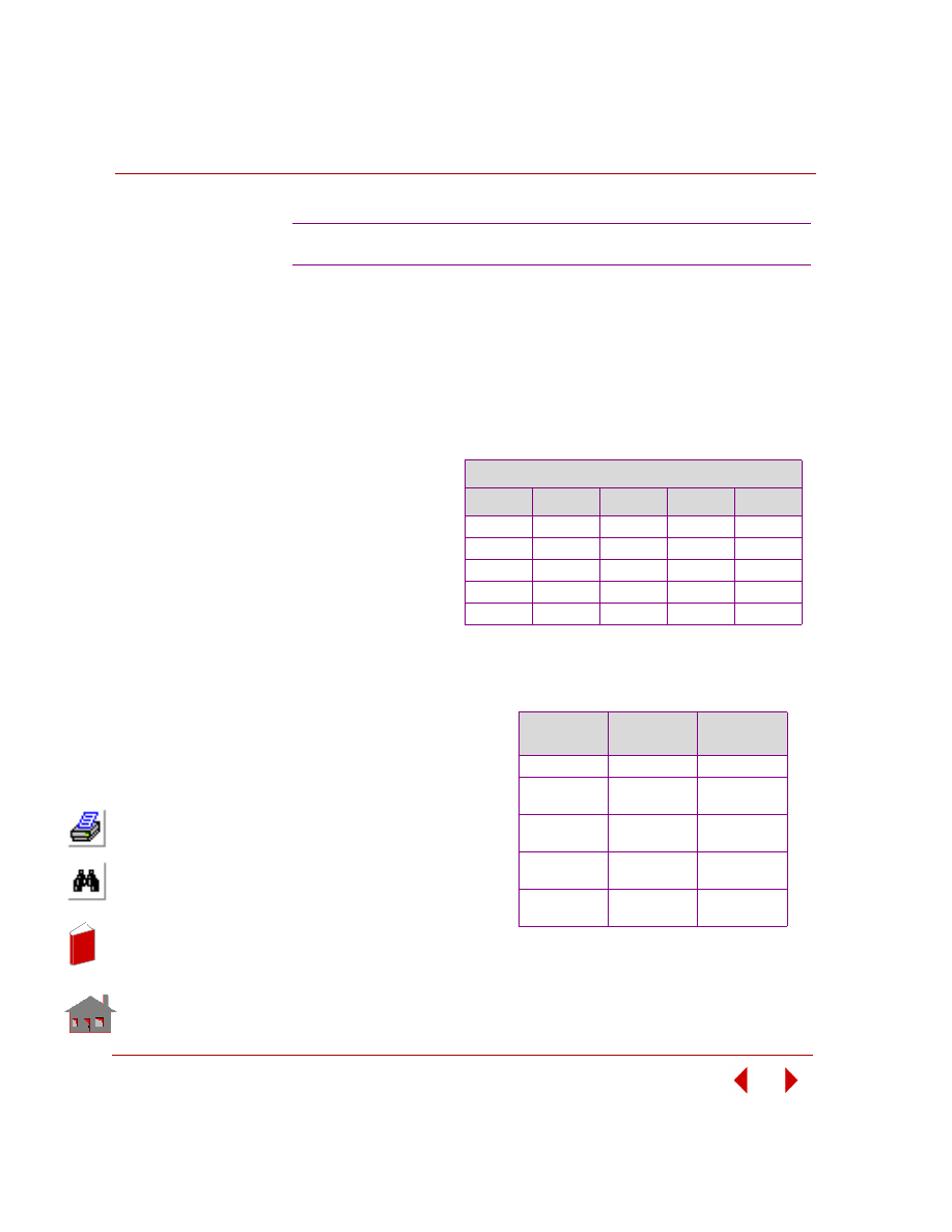
TYPE:
Linear thermal stress analysis, beam elements (BEAM3D).
REFERENCE:
Rygol, J., “Structural Analysis by Direct Moment Distribution,” Gordon and Breach
Science Publishers, New York, l968, pp. 292-294.
PROBLEM:
S23: Thermal Stress Analysis of a Frame
An irregular
frame subjected
to differential
temperature.
Find member
end moments.
Member Specifications
Member
d (ft)
b (ft)
Ar-r (ft)
lt-t (ft)
1
1.5
1.5
2.25
0.422
2
2.25
1.25
2.8125
1.187
3
2.0
1.5
3.0
1.0
4
2.5
1.25
3.125
1.628
5
2.0
1.5
3.0
1.0
GIVEN:
E
= 192857 tons/ft
2
α = 0.0000l ft/ft°C
COMPARISON OF RESULTS:
Moments (lb-in):
Member No.
COSMOSM
Reference
Solution
1
-17.96
-17.96
2
+17.96
-42.87
+17.96
-42.96
3
+38.73
-41.92
+38.64
-41.96
4
+84.79
-82.61
+84.92
-82.61
5
-57.50
+82.61
-57.40
+82.61
In
de
x
In
de
x
COSMOSM Basic FEA System
2-37
Part 2 Verification Problems
Figure S23-1
Figure S23-2
4
2
1
3
5
1
2
3
4
5
6
18'
27'
3'
3'
12'
A
A
B
B
Y
X
40 C
o
80 C
o
10 C
10 C
o
o
Problem Sketch and Finite Element Model
d
b
s
b
t
s
d
Section A-A
Section B-B
t
In
de
x
In
de
x
Chapter 2 Linear Static Analysis
2-38
COSMOSM Basic FEA System
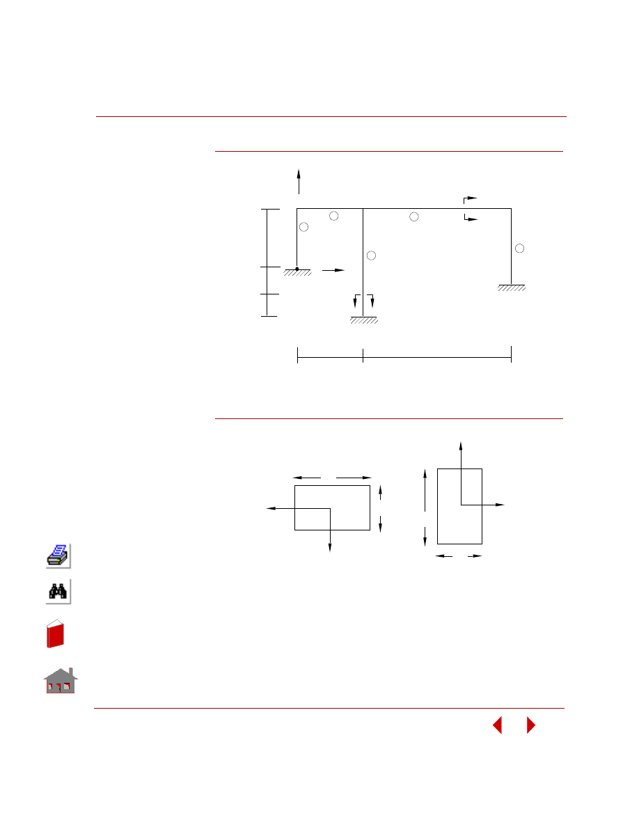
TYPE:
Linear thermal stress analysis, beam elements (BEAM2D).
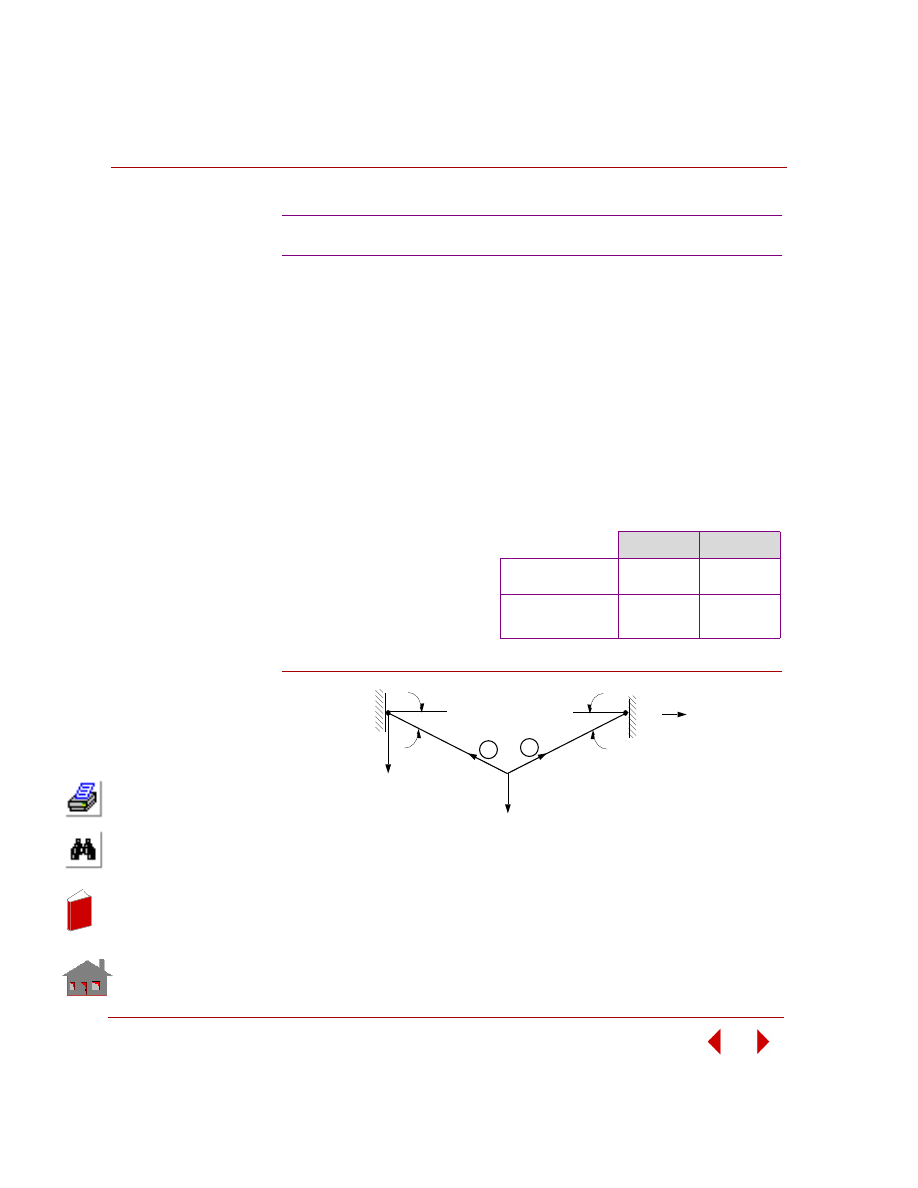
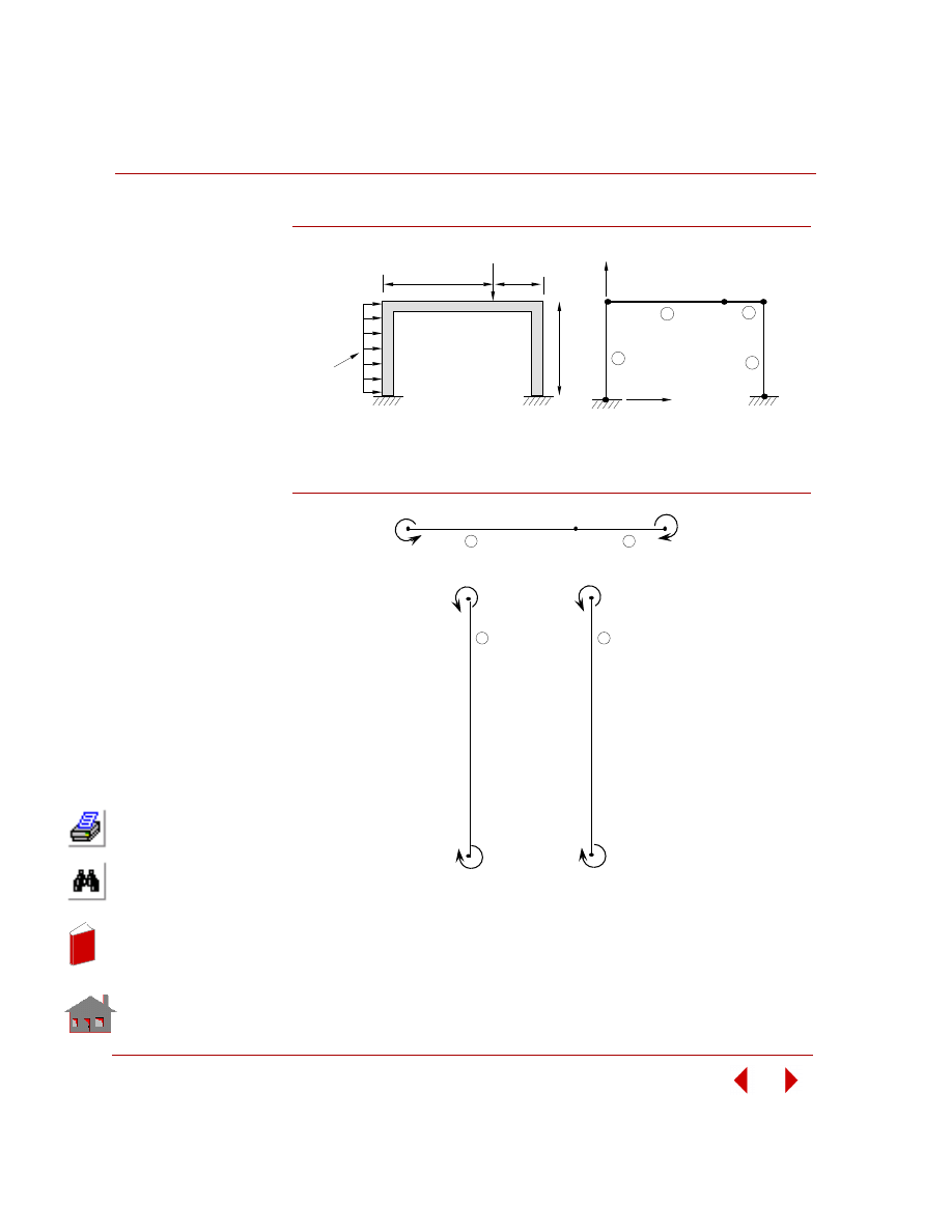
PROBLEM:
Determine displacements and end forces of the frame shown in the figure below due
to temperature rise at the nodes and thermal gradients of members as specified
below.
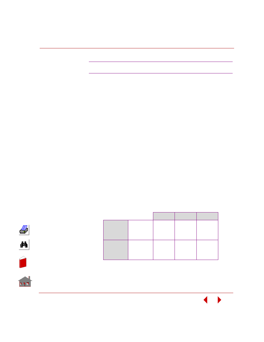
COMPARISON OF RESULTS:
Displacements at node 2 (in):
Figure S24-1
S24: Thermal Stress Analysis of a Simple Frame
GIVEN:
E
= 30,000 kips/in
2
α
= 0.65 x l0 in/in/°F
Element
No.
Difference in Temperature (
°
F)
S-dir
T-dir
1
72 0
2
0
13.5
δ
x
δ
y
Theory
-0.0583
0.1157
COSMOSM
-0.0583
0.1168
2
S
S
S
S
Se
e
e
e
ec
c
c
c
ctttttiiiiio
o
o
o
on
n
n
n
n
50
°
F
100
°
F
50
°
F
A
B
B
A
240"
1
2
x
120"
1
y
Problem Sketch and Finite Element Model
3
width
= 5"
t
depth
s
S
S
S
S
Se
e
e
e
ec
c
c
c
ctttttiiiiio
o
o
o
on
n
n
n
n
(y)
(z)
t (z)
s(y)
width
= 3"
depth
= 6"
In
de
x
In
de
x
COSMOSM Basic FEA System
2-39
Part 2 Verification Problems
TYPE:
Static analysis, shell elements (SHELL4).
REFERENCE:
Timoshenko, S. P., and Goodier, J. N., “Theory of Elasticity,” McGraw-Hill, New
York, 1951, p. 299.
PROBLEM:
Find the shear stress and the angle of twist for the square box beam subjected to a
torsional moment T.
GIVEN:
E
= 7.5 psi
ν
= 0.3
t
= 3 in
a
= 150 in
L
= 1500 in
T = 300 lb in
COMPARISON OF RESULTS:
r
*
θ
is calculated as:
θ =
Sin
-1
(resultant displacemet of node 25/distance from node 25 to the center of the cross
section)
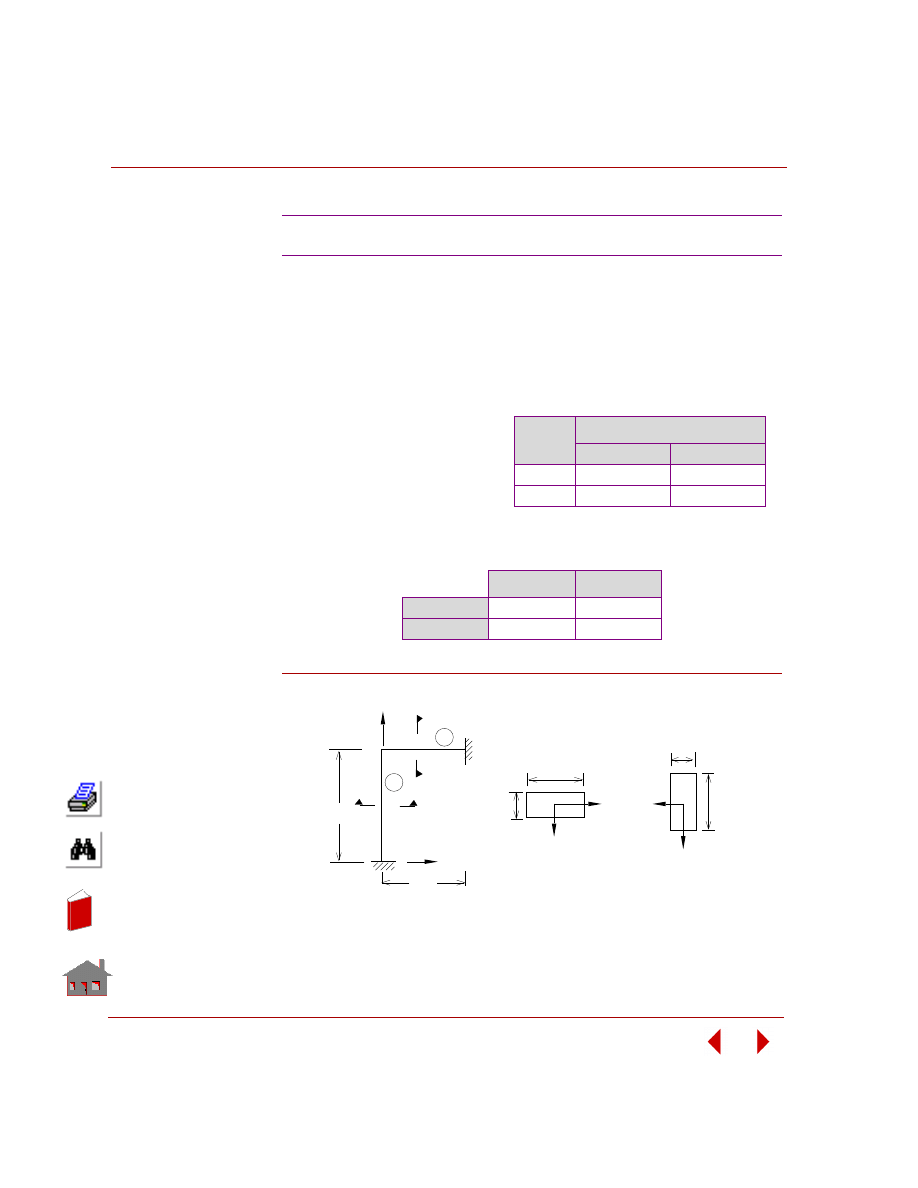
S25: Torsion of a Square Box Beam
Shear Stress
τ
psi
Rotation
θ
*
, rad
Theory
0.00222
0.0154074
COSMOSM
0.0021337 (average)
0.0154035*
In
de
x
In
de
x
Chapter 2 Linear Static Analysis
2-40
COSMOSM Basic FEA System
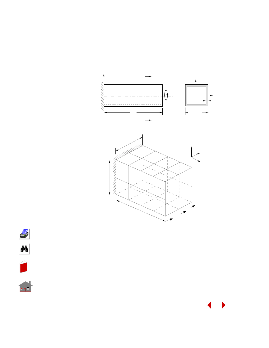
Figure S25-1
a
t
Y
Z
X
L
Z
Problem Sketch
Section
I-I
I
I
y
z
x
150
1500
.25
.5
.25
150
Finite Element Model
T
In
de
x
In
de
x
COSMOSM Basic FEA System
2-41
Part 2 Verification Problems
TYPE:
Static analysis, beam and truss elements (TRUSS3D, BEAM3D).
REFERENCE:
Beaufait, F. W., et. al., “Computer Methods of Structural Analysis,” Prentice-Hall,
Inc., New Jersey, l970, pp. l97-2l0.
PROBLEM:
The final end actions of the members and the reactions of the supports resulting from
the applied loading are to be determined for the structural system described in the
figure below. At the beam-column connection, joint 3, the beam is continuous and
the column is pin-connected to the beam.
GIVEN:
Cross-sectional area of beams
= A
1
= A
2
= 0.125 ft
2
Moment of inertia of beams
= I
1
= I
2
= 0.263 ft
4
Cross-sectional area of column = A
3
= 0.175 ft
2
Moment of inertia of column
= I
3
= 0.193 ft
4
E
= 1.44 x 10
4
kip/ft
2
K (spring stiffness)
= l200 kips/ft
COMPARISON OF RESULTS:
S26: Beam With Elastic Supports and a Hinge
Node 2
Node 4
Node 5
Reference
δ
x
(10
-3
ft)
δ
y
(10
-3
ft)
θ
z
(10
-3
rad)
1.0787
1.7873
0.0992
1.0787
-4.8205
0.3615
1.0787
-0.1803
-0.4443
COSMOSM
δ
x
(10
-3
ft)
δ
y
(10
-3
ft)
θ
z
(10
-3
rad)
1.0794
1.7869
0.0992
1.0794
-4.8205
0.3615
1.0794
-0.1803
-0.4443
In
de
x
In
de
x
Chapter 2 Linear Static Analysis
2-42
COSMOSM Basic FEA System
Figure S26-1
Figure S26-2
3
4
5
7
6
K
K
1
2
7
8
8
4
3
12'
24'
30'
5k
15k
X
5
Y
Problem Sketch and Finite Element Model
2
1
5k
15k
2.1k
(2.144)
2.1k
(2.144)
51.4 ft-k
(51.46)
9.2 k
(9.215)
5.8k
(5.785)
5.8k
(5.785)
11.3k
(11.36)
5k
(5)
5.8k
(5.785)
30.0 ft-k
(30.0)
In
de
x
In
de
x

COSMOSM Basic FEA System
2-43
Part 2 Verification Problems
TYPE:
Static analysis, beam elements (BEAM3D).
REFERENCE:
Laursen, Harold I., “Structural Analysis,” McGraw-Hill Book Co., Inc., New York,
1969, pp. 310-312.
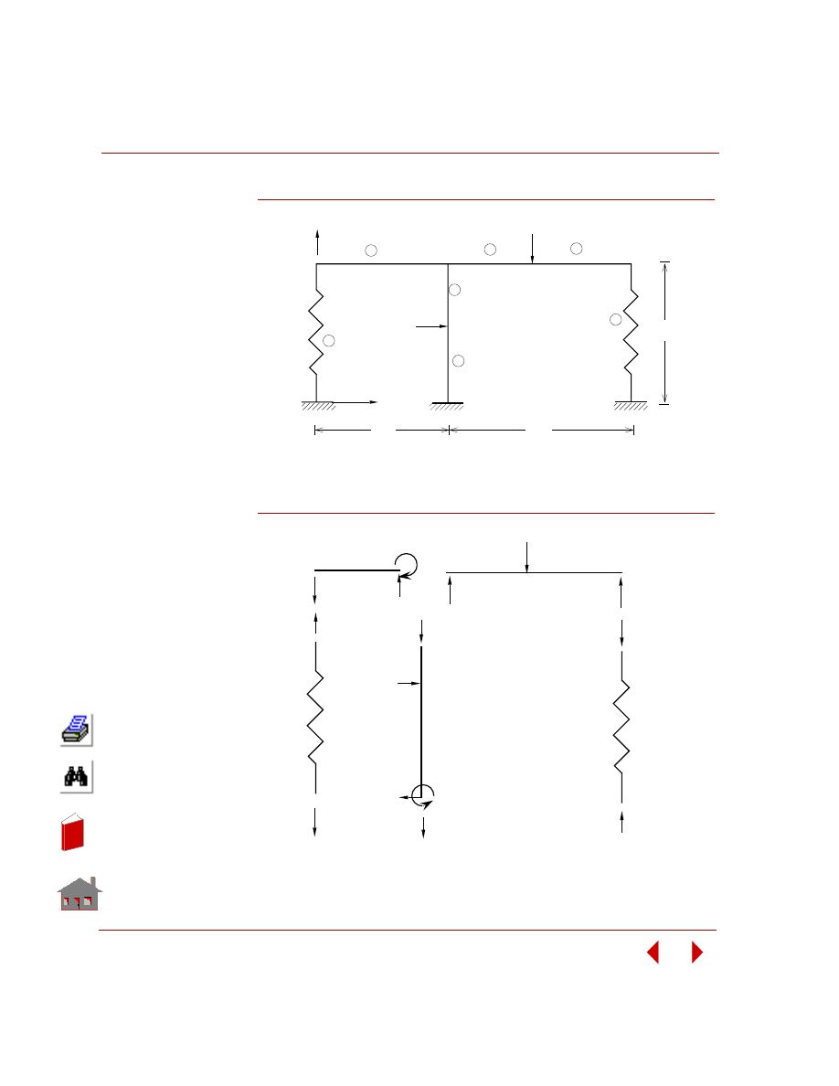
PROBLEM:
Determine the forces in the beam members under the loads shown in the figure.
Consider two separate load cases represented by the uniform pressure and the
concentrated force. Set up the input to solve each one individually and then combine
them together to obtain the final result.
GIVEN:
I
yy
= I
zz
= 0.3215 ft
4
I
= 0.6430 ft
4
A
1
= 3.50 ft
2
A
2,3
= 4.40 ft
3
A
4
= 2.79 ft
2
E
= 432 x 10
4
K/ft
2
Areas of members were made to be larger than the actual area in order to neglect
axial deformation.
COMPARISON OF RESULTS:
The results are shown in the figure below with COSMOSM results shown in
parentheses.
S27: Frame Analysis with Combined Loads
In
de
x
In
de
x
Chapter 2 Linear Static Analysis
2-44
COSMOSM Basic FEA System
Figure S27-1
Figure S27-2
5
4
3
2
1
Y
X
2k
5'
15'
15'
0.5 K/ft
E, I
1
2
3
4
Problem Sketch
Finite Element Model
4
2
3
1
1
2
3
4
5
2
10.547 K ft
(10.51)
6.766K ft
(6.76)
28.256K ft
(28.32)
10.682 K ft
(10.67)
In
de
x
In
de
x
COSMOSM Basic FEA System
2-45
Part 2 Verification Problems
TYPE:
Static analysis, 3D beam element (BEAM3D).
REFERENCE:
Boresi, A. P., Sidebottom, O. M., Seely, F. B., Smith, J. O., “Advanced Mechanics
of Materials,” John Wiley and Son, Third Edition, 1978.
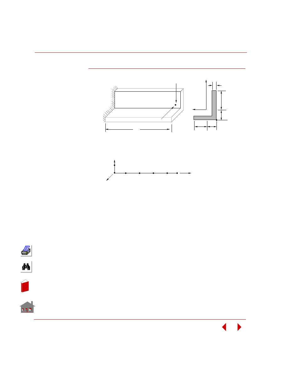
PROBLEM:
An unsymmetric cantilever beam is subjected to a concentrated load at the free end.
Determine the tip displacement of the beam, the end forces and the stress at y = 8,
z = -2 at the clamped end.
GIVEN:
COMPARISON OF RESULTS:
S28: Cantilever Unsymmetric Beam
E
= 2 x 10
7
N/cm
2
Fy = -8 N
h
1
= 4 cm
b
1
= 2 cm
L
= 500 cm
F
z
= -4 N
h
2
= 8 cm
b
2
= 6 cm
A = 19 cm
2
I
yy
= 100.3 cm
4
I
zz
= 278.3 cm
4
I
yz
= 97.3 cm
4
I
xx
= J = 6.333 cm
4
t
= 1 cm
Theory
COSMOSM
Node 6
Translation in Y Dir (cm)
Translation in Z Dir (cm)
Rotation about X Axis (rad)
-0.1347
-0.2140
0
-0.1346
-0.21364
0
Node 1
Moment about Y Axis (N-cm)
Shear in Z Dir (N)
Stress at Y = 8, Z = 2
-2000.0
4.0
155.74 Tension
-2000.0
4.0
155.8 Tension
In
de
x
In
de
x
Chapter 2 Linear Static Analysis
2-46
COSMOSM Basic FEA System
Figure S28-1
S.C.
Unsymmetric Beam Structure
L
Fz
Fy
b
2
1
h
h
t
Y
C.G.
b
Cross Section
Problem Sketch
Z
1
2
3
4
5
6
7
Finite Element Model
X
Y
2
1
In
de
x
In
de
x
COSMOSM Basic FEA System
2-47
Part 2 Verification Problems
TYPE:
Static analysis, composite shell (SHELL9L), and solid element (SOLIDL).
REFERENCE:
Jones, Robert M., “Mechanics of Composite Materials,” McGraw-Hill, N. Y., l975,
p. 258.
PROBLEM:
Calculate the maximum deflection of a simply supported square antisymmetric
angle-ply under SINUSOIDAL loading. The plate is made up of 6 layers, where the
top layer material axis orientation makes 45 degree angle with x-axis. To impose
simply-supported boundary conditions, 2 layers of composite solid elements (each
has 3 layers of different
material orientation)
through the thickness
are required.
GIVEN:
a
= b = 20 in
E
a
=
40E6
psi
h
= 0.01 in
E
b
= lE6 psi
ν =
0.25
G
ab
= G
ac
= G
bc
= 5E5 psi
p
= cos (
π x/a) cos (π y/b)
p
o
= 1E-3
COMPARISON OF RESULTS:
S29A, S29B: Square Angle-Ply Composite
Plate Under Sinusoidal Loading
Max. Deflection
Reference Solution
0.256
COSMOSM
SOLIDL
0.258
SHELL9L
0.258
b
a
Z
X
Y
h
55
5
51
71
21
75
25
Problem Sketch and
Finite Element Model
Figure S29-1
In
de
x
In
de
x
Chapter 2 Linear Static Analysis
2-48
COSMOSM Basic FEA System
S
TYPE:
Static analysis, shell elements (SHELL3).
REFERENCE:
Pryor, Charles W., Jr., and Barker, R. M., “Finite Element Bending Analysis of
Reissner Plates,” Engineering Mechanics Division, ASCE, EM6, December, l970,
pp. 967-983.
PROBLEM:
Find the effect of transverse shear on maximum deflection of an isotropic simply
supported plate subjected to a constant pressure, q.
GIVEN:
MODELING HINTS:
The input data corresponds to h = 0.1008 and the other inputs can be obtained by
changing the thickness in the given input data. Due to symmetry, only one quarter of
the plate is considered.
COMPARISON OF RESULTS:
S30: Effect of Transverse Shear
on Maximum Deflection
a
= b = 24 in
E
= 30E6 psi
H = varies according to
thickness ratio (H/a)
ν
= 0.3
q
= 30 psi
Thickness
Ratio H/a
Thickness H
β
Coefficient
*
Difference
(%)
Reissner Theory
COSMOSM
0.000042
0.001008
0.04436
0.04438
**
0.045
0.00042
0.01008
0.04436
0.04438
**
0.045
0.0042
0.1008
0.04436
0.04438
**
0.045
0.05
1.20
0.044936
0.044772
***
0.36
0.1
2.40
0.046659
0.046510
***
0.32
0.15
3.60
0.049533
0.049405
***
0.26
0.2
4.80
0.053555
0.053458
***
0.180
0.25
6.00
0.058727
0.058669
***
0.10
0.3
7.20
0.065048
0.065038
***
0.02
*
β
= EH
3
W
max
/qa
4
**
Thin Shell (SHELL3)
**
Thick
Shell (SHELL3T)
In
de
x
In
de
x
COSMOSM Basic FEA System
2-49
Part 2 Verification Problems
Figure S30-1
Figure S30-2
b
a
Z
Y
X
H
Problem Sketch
q
6.0
Present Finite Element
Reissner's Theory
Classical Theory
0.0
0.3
0.05
1.0
Thickness Ratio, H/a
Coefficient,
β
x10
2
-
b =
W
max
qa
4
0.0
In
de
x
In
de
x
Chapter 2 Linear Static Analysis
2-50
COSMOSM Basic FEA System
TYPE:
Static analysis, shell element (SHELL4L).
REFERENCE:
Jones, Robert M., “Mechanics of Composite Materials,” McGraw Hill, N. Y., l975,
p. 258.
PROBLEM:
Calculate the maximum deflection of a simply supported square antisymmetric
angle-ply under sinusoidal loading. The plate is made of 4-layers where the top layer
material axis orientation makes l5 degree angle with the X-axis.
GIVEN:
a
= b = 20 in
h
= 1 in
E
a
= 40E6 psi
E
b
= 1E6 psi
ν
= 0.25
G
ab
= G
ac
= G
bc
= 5E5 psi
p
= cos (
π x/a)
cos (
π y/b)
COMPARISON OF RESULTS:
S31: Square Angle-Ply Composite
Plate Under Sinusoidal Loading
W
max
(inch)
Theory
4.24E-4
COSMOSM
4.40E-4
Figure S31-1
Z
Y
X
h
a
1
25
21
5
Problem Sketch and Finite Element Model
b
In
de
x
In
de
x
COSMOSM Basic FEA System
2-51
Part 2 Verification Problems
TYPE:
Static analysis, substructuring using truss elements (TRUSS2D).
PROBLEM:
Determine the deflections of a tower loaded at top, using multi-level substructures.
GIVEN:
COMPARISON OF RESULTS:
S32A, S32B, S32C, S32D, S32M:
Substructure of a Tower
E
= 10 x l0
6
psi
P
= 1000 lb
h
= l00 in
L
= 30 in
Cross-sectional areas of vertical
and horizontal bars = l in
2
Cross-sectional areas of diagonal
bars = 0.707 in
2
Node Number
Deflection (10
-3
inch)
Full
Structure
Sub-
structure
COSMOSM Using
Full Structure
COSMOSM Using
Substructure
X
Y
X
Y
1
1(A)
0
0
0
0
2
5(A)
7.9761
9.1679
7.9761
9.1678
9
5(B)
14.6226
25.3632
14.6226
25.3631
13
5(C)
19.9360
46.8896
19.9359
46.8893
17
5(M)
23.9168
71.9909
23.9167
71.9905
21
3(D)
26.5878
99.3979
26.5877
99.3973
4
4(A)
-2.1815
3.4329
-2.1815
3.4328
6
2(B)
-4.0240
8.9940
-4.0239
8.9940
10
2(C)
-6.7108
25.1829
-6.7108
25.1828
14
2(M)
-8.0642
46.7075
-8.0641
46.7072
18
6(M)
-8.0834
71.7683
-8.0833
71.7678
22
4(D)
-6.7458
98.0790
-6.7457
98.0784
In
de
x
In
de
x
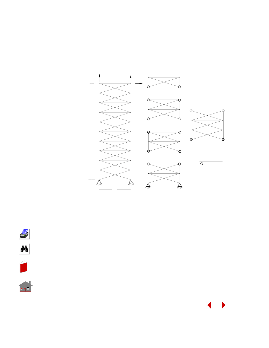
Chapter 2 Linear Static Analysis
2-52
COSMOSM Basic FEA System
Figure S32A-1
1
3
5
9
13
17
21
22
18
14
10
6
2
Problem Sketch
(Full Structure)
h
L
1
4
3
2
(D) Super Element # 4 - Level
1
2
3
4
5
6
(B) Super Element #2 - Level 2
8
2
1
3
4
5
6
7
(M) Main Element
1
2
3
4
5
6
(C) Super Element #3 - Level 1
Finite Element Models
P
P
P
4
7
8
11
12
15
16
19
20
Super Nodes
1
2
3
4
5
6
(A) Super Element #1 - Level 3
In
de
x
In
de
x
COSMOSM Basic FEA System
2-53
Part 2 Verification Problems
TYPE:
Static analysis, substructuring using shell, beam and truss elements (SHELL4,
BEAM3D, TRUSS3D).
PROBLEM:
By using substructure method, determine the deflection of an airplane through the
assembly of the calculations concerning separate parts, of the plane.
COMPARISON OF RESULTS:
Figure S33A-1
S33A, S33M: Substructure of an Airplane (Wing)
Node
Number
Deflection (Z-Direction) (inch)
COSMOSM Using
Full Structure
COSMOSM Using
Substructure
16
10.100
10.178
17
8.0671
8.1024
18
13.800
13.894
19
10.666
10.708
20
8.7693
8.9513
21
12.276
12.958
45
46
47
16'
P
60'
Problem Sketch
(Full Structure)
45
46
47
Note: Nodes
with are
Super Nodes
In
de
x
In
de
x
Chapter 2 Linear Static Analysis
2-54
COSMOSM Basic FEA System
TYPE:
Static analysis, stress stiffening, beam elements (BEAM3D).
REFERENCE:
Timoshenko, S. P., “Strength of Materials, Part II, Advanced Theory and Problems,”
3rd Edition, D. Von Nostrand Co., Inc., New York, l956, p.42.
PROBLEM:
A tie rod subjected to the action of a tensile force S and a uniform lateral load q.
Determine the maximum deflection z, and the slope at the left end. In addition,
determine the same two quantities for the unstiffened tie rod (S = 0).
GIVEN:
L
= 200 in
E
= 30E6 psi
S
= 2l,972.6 lb
q
= l.79253 lb/in
b
= h = 2.5 in
CALCULATED INPUT:
Area = 6.25 in
2
l =
3.2552
in
4
MODELING HINTS:
Due to symmetry, only one-half of the beam is modeled.
S34: Tie Rod with Lateral Loading
In
de
x
In
de
x
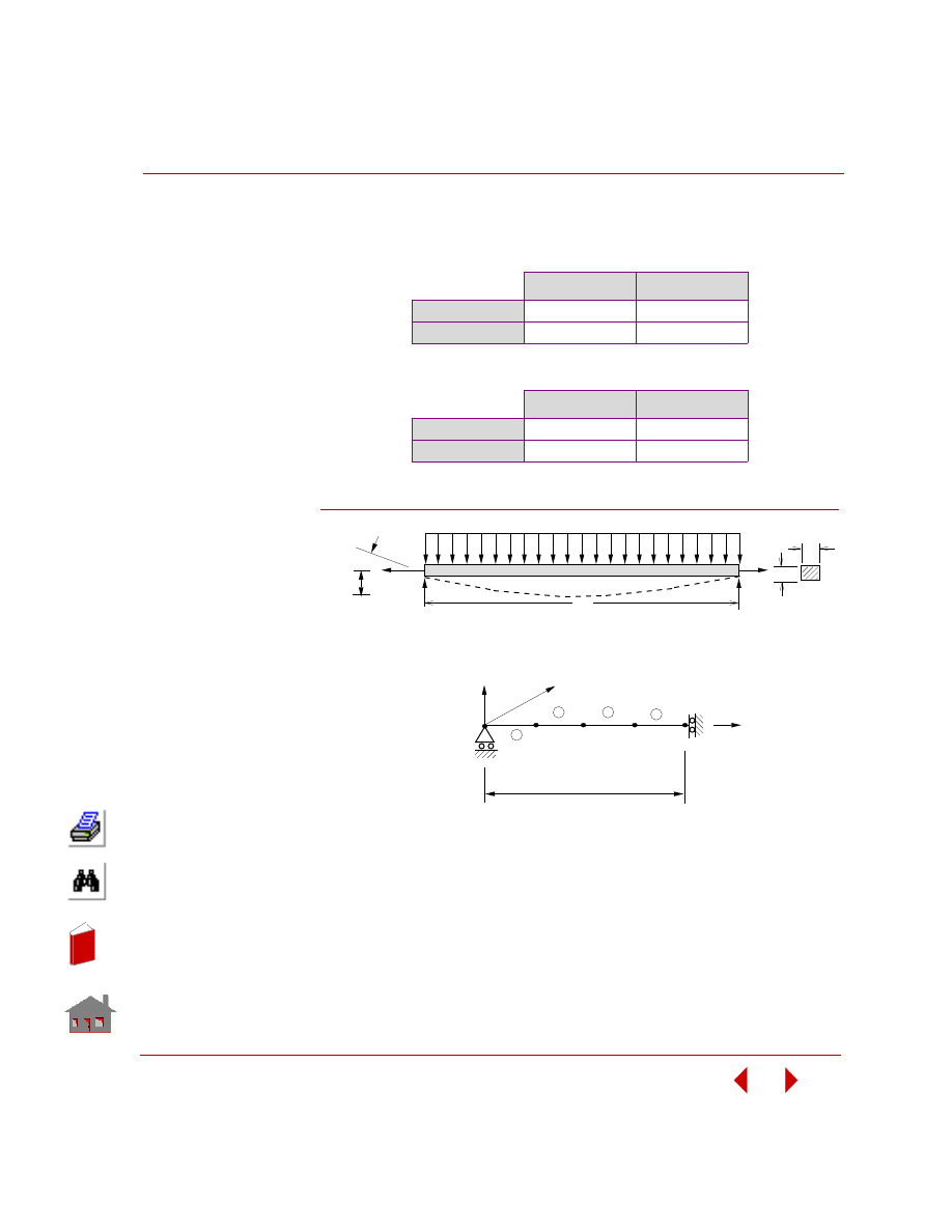
COSMOSM Basic FEA System
2-55
Part 2 Verification Problems
COMPARISON OF RESULTS:
S
≠
0 (Stiffened)
S = 0 (Unstiffened)
Figure S34-1
Z
max
, in
θ
rad
Theory
-0.2
0.0032352
COSMOSM
-0.19701
0.0031776
Z
max
, in
θ
rad
Theory
-0.382406
0.006115
COSMOSM
-0.37763
0.0060229
b
L
h
q
S
Zmax
θ
Problem Sketch
4
3
2
1
Z
Y
L/2
1
2
3
4
5
X
Finite Element Model
S
In
de
x
In
de
x

Chapter 2 Linear Static Analysis
2-56
COSMOSM Basic FEA System
TYPE:
Static analysis, solid and composite solid elements (SOLID, SOLIDL).
REFERENCE:
Reddy, N. J. “Exact Solutions of Moderately Thick Laminated Shells,” J. Eng.
Mech. Div. ASCE, Vol. 110, (1984), pp. 794-809.
PROBLEM:
Calculate the center deflection of a simply supported spherical cap under uniform
pressure (q = 1.) in the direction normal to the cap surface. To impose simply-
supported boundary conditions by solid elements, 2 layers of elements through the
thickness are required.
Two types of material properties are being tested, each by a different solid element.
A. Isotropic material is handled by SOLID element (S35A).
B. Composite material, 4 layers with the orientation 0
°/90°/90°/0°, is analyzed by
SOLIDL element (S35B). The lower layer of element is modeled by 2 layers of
material orientation 0
°/90° and the upper one is by 90°/0°.
To capture the geometry of a curved surface by a bi-linear shape function accurately,
at least 8 elements per side have to be used. The model used below is an 8x8x2 mesh.
GIVEN:
S35A, S35B: Spherical Cap Under
Uniform Pressure (Solid)
Geometry:
R
= 96
h
= 0.32 in
Length of side a =b = c = d = 32 in
Material Properties:
1. S35A: Isotropic
E = 1E7 psi
ν = 0.3
2. S35B: Composite 0
°/90°/90°/0°
E
x
= 25E6 psi
E
y
= E
z
= 1E6 psi
ν
xy
= 0.25
ν
yz
=
ν
xy
= 0
G
yz
= 0.2E6 psi
G
xy
= G
xz
= 0.5E6 psi
In
de
x
In
de
x
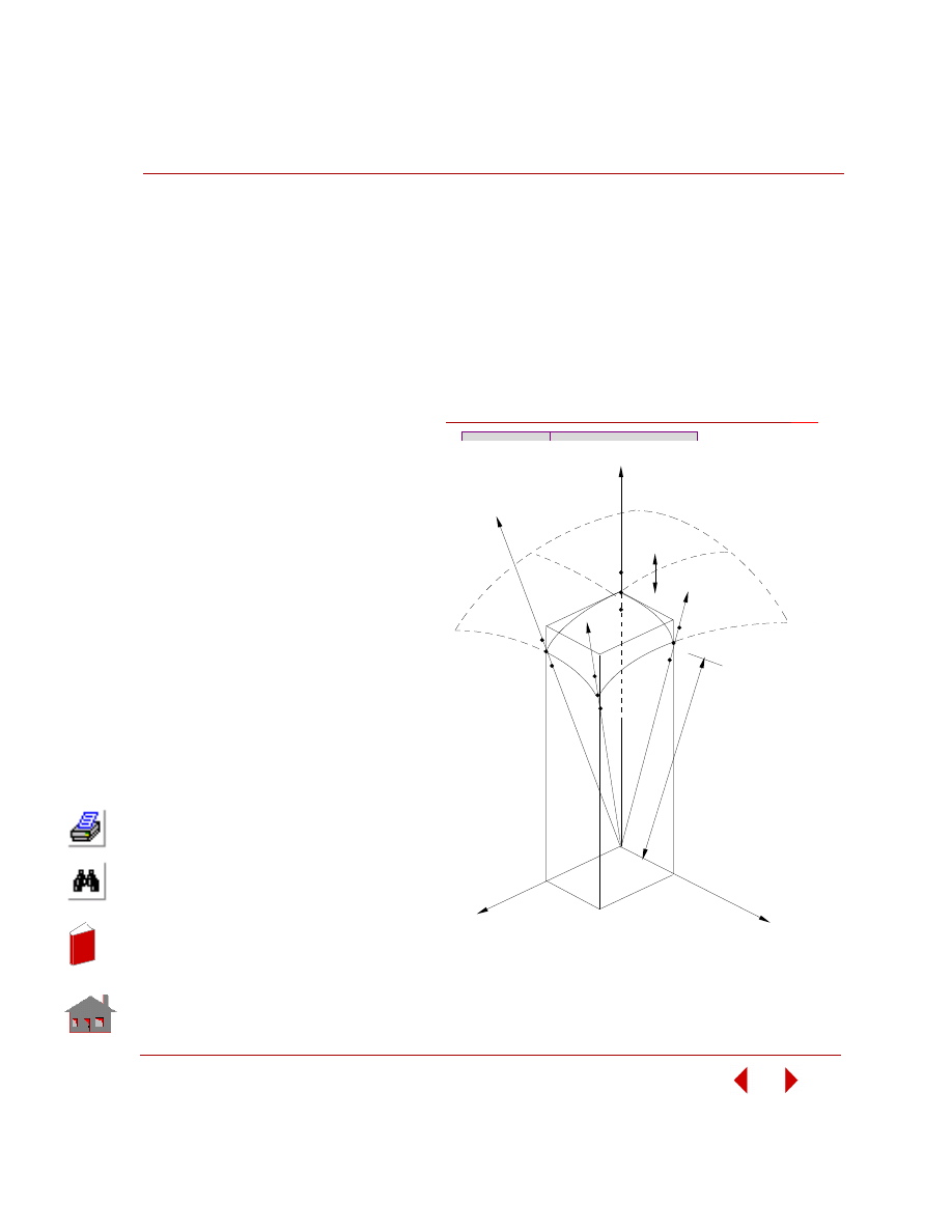
COSMOSM Basic FEA System
2-57
Part 2 Verification Problems
MODELING HINTS:
Boundary Conditions
Due to symmetry:
1. All nodes on plane A, Uy = 0
2. All nodes on plane B, Ux = 0
Simply supported:
1. All nodes on side C, radial displacement
= 0, Disp. on plane C = 0
2. All nodes on side D, radial displacement
= 0, Disp. on plane D = 0
COMPARISON OF RESULTS:
Element
W
max
(inch)
(1) Isotropic
Exact
SOLID
0.3139E-2
0.3232E-2
(2) Composite
Exact
SOLIDL
0.199E-1
0.2007E-1
243
a
c
d
1
sym.
9
162
81
R
PLAN
E C
PLAN
E D
PLAN
E A
X
Y
Z
b
PLAN
E D
PLAN
E C
Problem Sketch and Finite Element Model
PLAN
E B
163
82
h
90
171
sym
.
154
73
235
Figure S35A-1
In
de
x
In
de
x

Chapter 2 Linear Static Analysis
2-58
COSMOSM Basic FEA System
TYPE:
Static analysis, substructuring using plate elements (SHELL4).
REFERENCE:
Timoshenko, S., “Theory of Plates and Shells,” McGraw-Hill, New York, 1940, p.
113-198.
PROBLEM:
Calculate the deflections of a simply supported isotropic plate subjected to uniform
pressure p using the substructuring technique. Nodes 11 through 15 are super nodes
which connect the substructure to the main structure.
GIVEN:
E
= 30 x 10 psi
ν
= 0.3
h
= 0.5 in
p
= 5 psi
a
= 16 in
b
= 10 in
MODELING HINTS:
Due to symmetry, a quarter of a plate is taken for modeling.
COMPARISON OF RESULTS:
Timoshenko gives the expression for deflection w in the z-direction with origin at
the corner of the plate.
S36A, S36M: Substructure of a
Simply Supported Plate
In
de
x
In
de
x
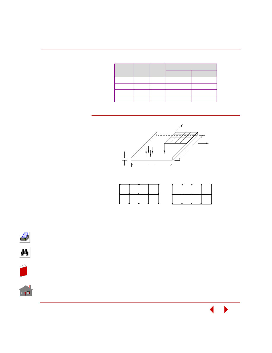
COSMOSM Basic FEA System
2-59
Part 2 Verification Problems
Figure S36A-1
Node No.
X
(inch)
Y
(inch)
W
(inch)
Theory
COSMOSM
1
0
0
0.0012103
0.00121329
2
2
0
0.0011338
0.00113636
3
4
0
0.0009043
0.00090247
4
6
0
0.0005150
0.00051044
16 17 18 19 20
6 7 8 9 10
11 1 2 13 14 15
21 22 23 24 25
Z
Y
X
5
h
1
b
25
a
Problem Sketch
1 2 3 4 5
11 1 2 13 14 15
(A) Main Structure
(B) Substructure
Finite Element Models
21
P
In
de
x
In
de
x
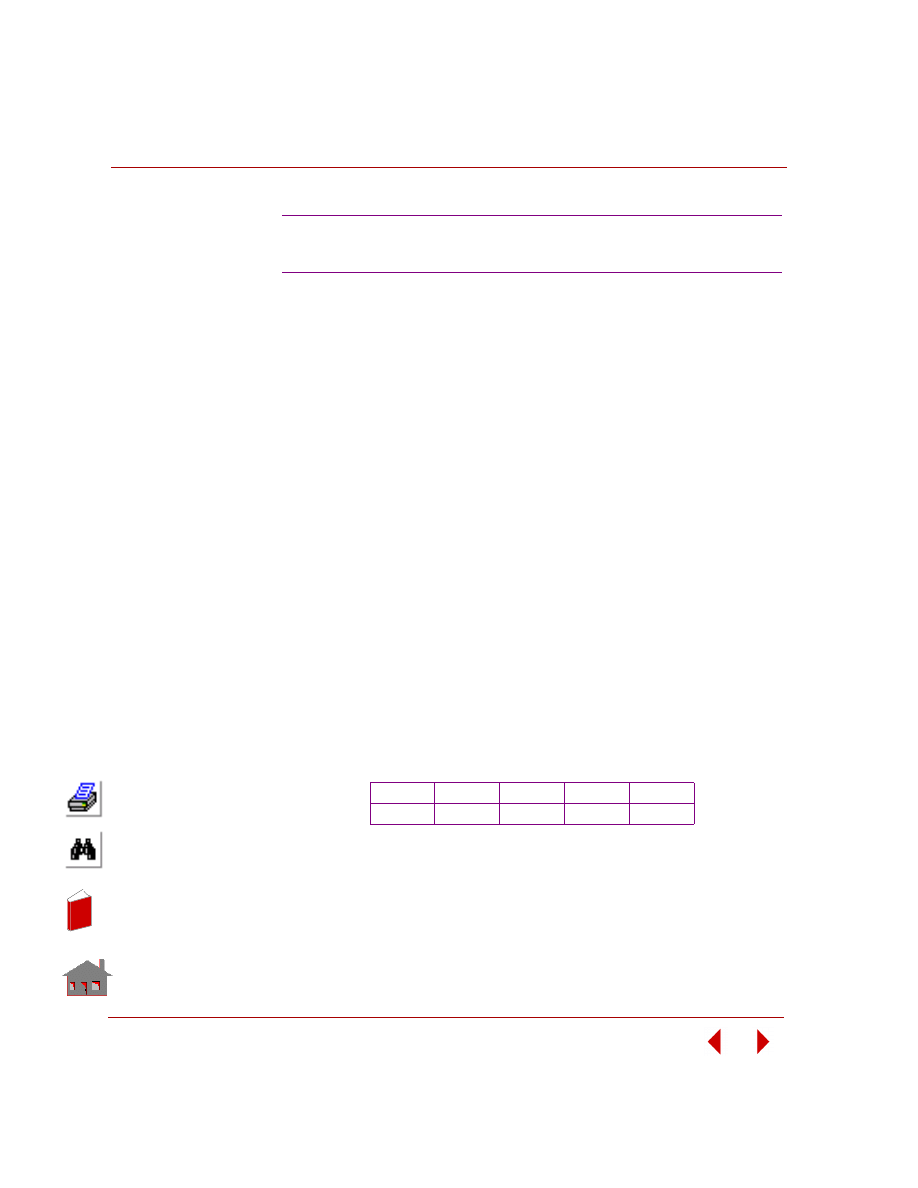
Chapter 2 Linear Static Analysis
2-60
COSMOSM Basic FEA System
TYPE:
Static analysis, axisymmetric shell elements (SHELLAX).
REFERENCE:
William Weaver, Jr., and Paul R. Johnston, “Finite Elements for Structural
Analysis,” Prentice-Hall, Inc., l984, p. 275.
PROBLEM:
Determine the horizontal displacement of a hyperboloidal shell under uniform ring
load around free edge.
GIVEN:
Equation of the hyperboloid:
X
2
= 0.48 (Y - H
0
)
2
+ R
2
MODELING HINTS:
Nodes at the top of the tower are spaced closely because of the concentrated ring
load. Nodal spacing is as follows:
And it is to be noted that the ring load should be input per radian length, since the
radius at the top of the shell is 865.3323 in, the load is 865.33 kip/rad.
S37: Hyperboloidal Shell Under Uniform
Ring Load Around Free Edge
R
0
= 600 in
R
1
= l200 in
H = 2400 in
H
0
= l500 in
t
= 8 in
E
= 3000 kip/sq in
ν
= 0.3
P
= l kip/in
Nodes
1-11
11-21
21-29
29-39
D
y
(in)
10
20
75
150
In
de
x
In
de
x
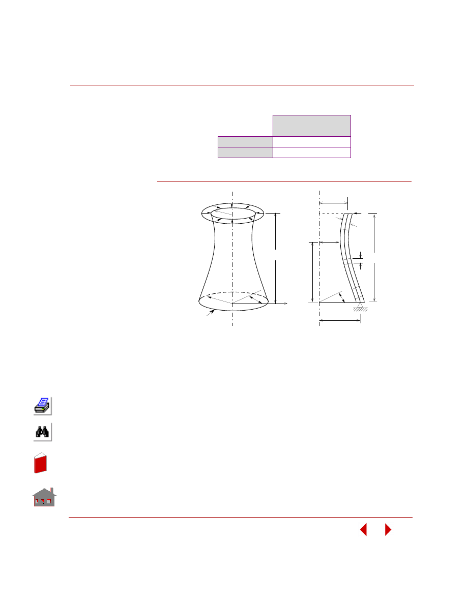
COSMOSM Basic FEA System
2-61
Part 2 Verification Problems
COMPARISON OF RESULTS:
Figure S37-1
Maximum Displacement
at Node 41 (inch)
Theory
-0.904
COSMOSM
-0.89705
Simply
Supported
R2
H
P
r
Problem Sketch
θ
R1
4 1
2 2
2 3
1
H
P
R
R
R
t
o
2
1
∆
θ
H
o
x
Section
In
de
x
In
de
x
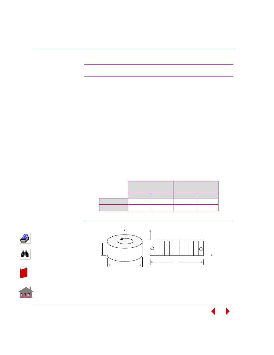
Chapter 2 Linear Static Analysis
2-62
COSMOSM Basic FEA System
TYPE:
Static analysis, axisymmetric (PLANE2D) elements, centrifugal loading.
REFERENCE:
S. P. Timoshenko and J. N. Goodier, “Theory of Elasticity,” McGraw-Hill, New
York, l970, p. 80.
PROBLEM:
A solid disk rotates about center 0 with angular velocity
ω. Determine the stress
distribution in the disk.
GIVEN:
COMPARISON OF RESULTS:
Figure S38-1
S38: Rotating Solid Disk
E
= 30 x l0
6
psi
DENS = 0.02 lb sec
2
/in
4
ν
= 0.3
h
= l in
ω = 25 rad/sec
R
= 9 in
Location
Element 1 (r = 0.5 inch)
Location
Element 9 (r = 8.5 inch)
σ
r
psi
σ
θ psi
σ
r
psi
σ
θ psi
Theory
416.37
416.91
45.12
203.16
COSMOSM
416.82
416.82
46.18
202.03
1
X
R
h
20
Y
2
Y
19
1
9
2R
Problem Sketch and Finite Element Model
ω
In
de
x
In
de
x
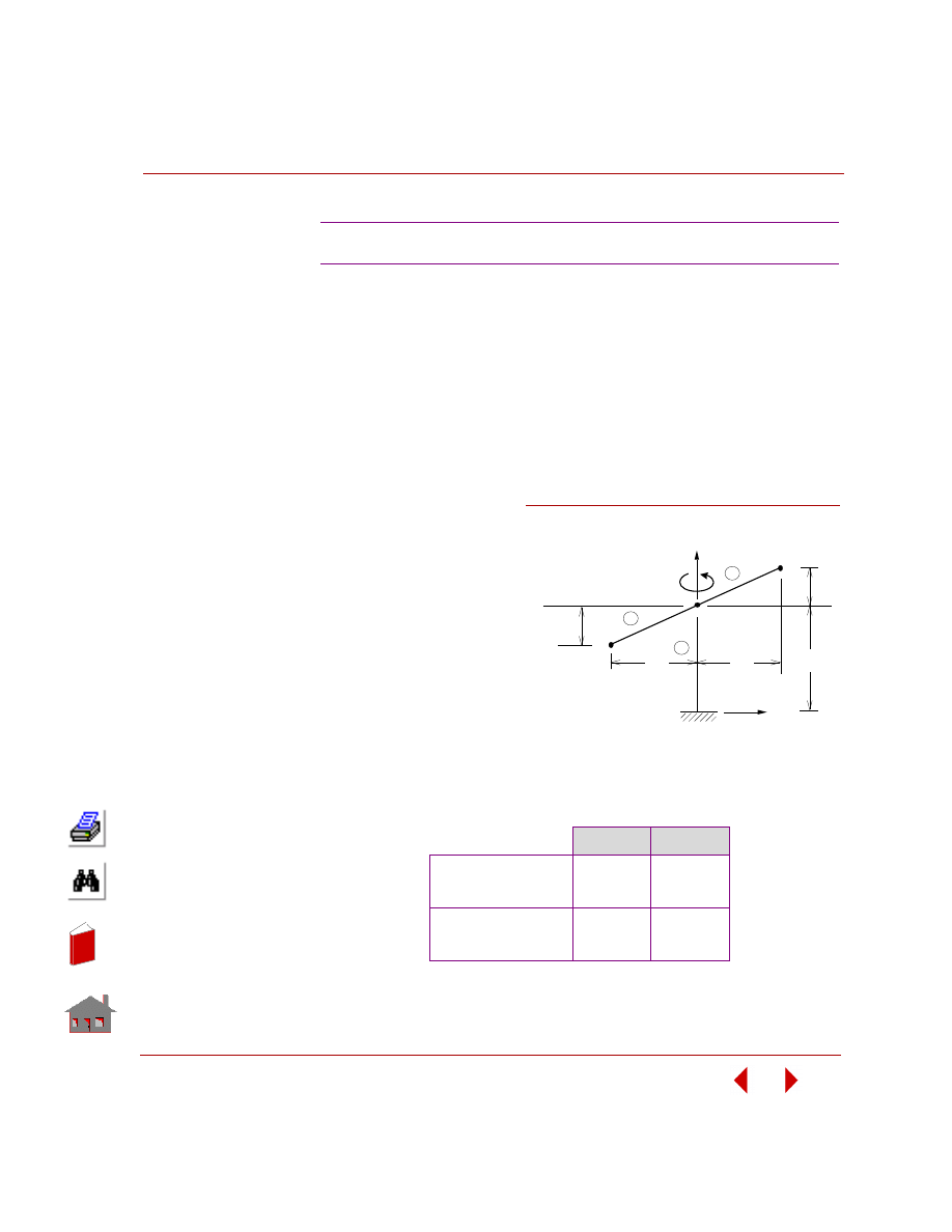
COSMOSM Basic FEA System
2-63
Part 2 Verification Problems
TYPE:
Static analysis, centrifugal loading, beam and mass elements (BEAM3D, MASS).
PROBLEM:
The model shown in the figure is assumed to be rotating about the y-axis at a
constant angular velocity of 25 rad/sec. Determine the axial forces and bending
moments in the supporting beams and columns due to self-weight and rotational
inertia.
GIVEN:
COMPARISON OF RESULTS:
S39: Unbalanced Rotating Flywheel
Element Properties:
A = 100 in
2
Iyy = Izz = l000 in
4
Ixx = 2000 in
4
E
= 30 x l0
6
psi
G = 10 x l0
6
psi
ρ
= 0.0l lb-sec
2
/in
4
Inertial Properties:
m
3
= m
4
= l0
a
y
= -l00 in/sec
2
w = 25 rad/sec
Theory
COSMOSM
Element 2, Node 2
Axial Force
Bending Moment
58,800
412,000
58,800
412,000
Element 3, Node 2
Axial Force
Bending Moment
61,200
388,000
61,200
388,000
Figure S39-1
ω
1
10
6
X
1
3
8
8
Y
6
m
4
m
2
3
2
Problem Sketch and Finite Element Model
In
de
x
In
de
x
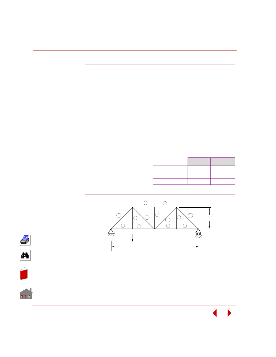
Chapter 2 Linear Static Analysis
2-64
COSMOSM Basic FEA System
TYPE:
Static analysis, truss elements (TRUSS2D).
REFERENCE:
Hsieh, Y. Y., “Elementary Theory of Structures,” Prentice-Hall Inc., l970, pp. l62-
l63.
PROBLEM:
Calculate the reactions and the vertical deflection of joint 2 of the loaded truss
shown below subject to a concentrated load.
Figure S40-1
S40: Truss Structure Subject to a
Concentrated Load
GIVEN:
COMPARISON OF RESULTS:
E
= 30,000 kips/in
2
P
= 64 kips
L (ft)/A(in) = 1 for all members
Theory
COSMOSM
Deflection of Joint 2 0.006733 in
0.006733 in
Reaction at Node 1
48 K
48 K
Reaction at Node 5
16 K
16 K
12
13
11
10
6
5
2
7
3
8
4
9
1
2
3
4
5
6
7
8
P
32 ft
4 at 24 ft = 96 ft
Problem Sketch and Finite Element Model
1
In
de
x
In
de
x
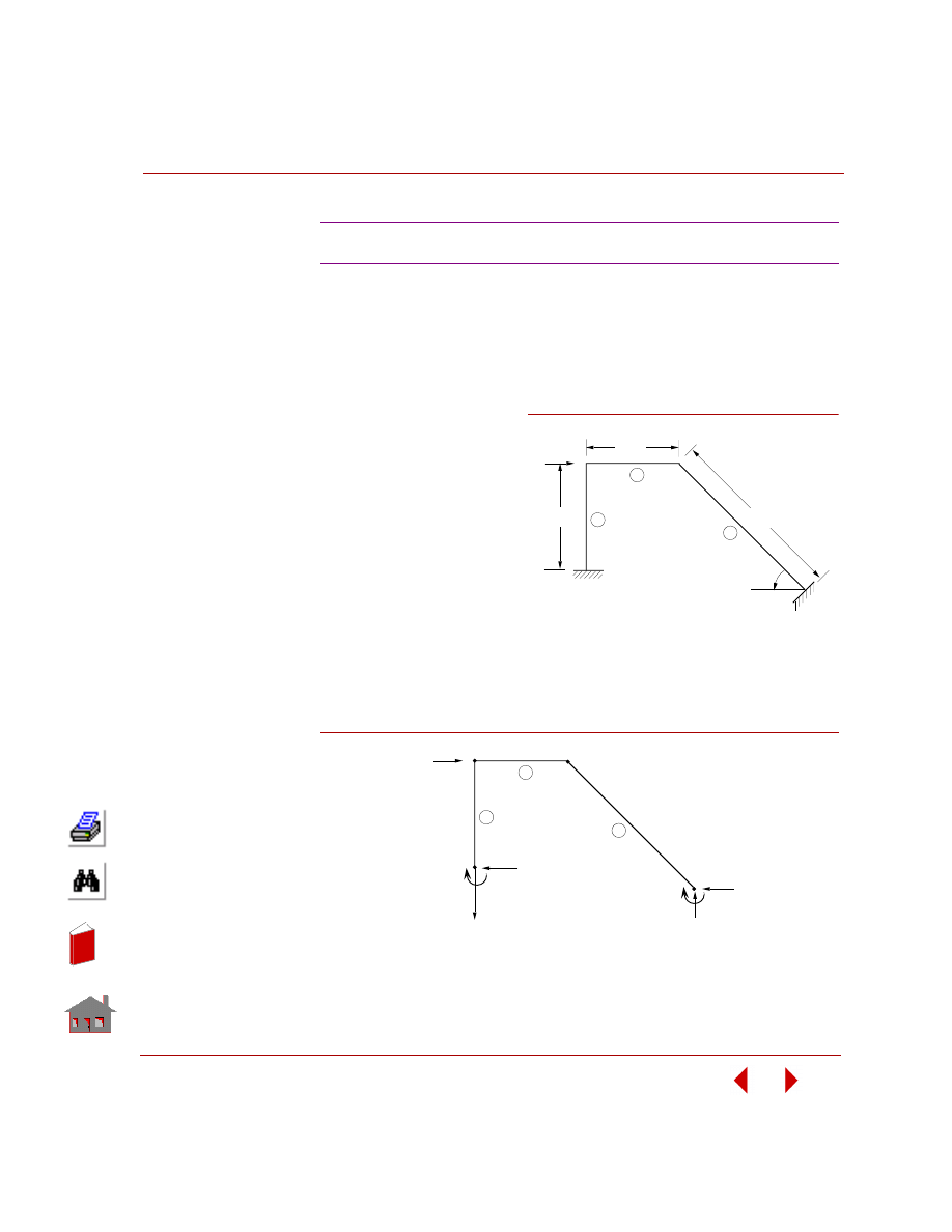
COSMOSM Basic FEA System
2-65
Part 2 Verification Problems
TYPE:
Static analysis, beam element (BEAM2D).
REFERENCE:
Hsieh, Y. Y., “Elementary Theory of Structures,” Prentice-Hall Inc., l970, pp. 258-
259.
PROBLEM:
Determine the reactions for
the frame shown below.
GIVEN:
E
= 30 x 10
6
psi
A = 0.1 in
2
The relative values of 2EI/L:
for element l = l lb-in
for elements 2, 3 = 2 lb-in
COMPARISON OF RESULTS:
The free body diagram for the structural system is given below and COSMOSM
results are given in parentheses.
Figure S41-2
S41: Reactions of a Frame Structure
25 ft.
15 ft.
1
2
3
4
15 ft.
P
1
2
3
Problem Sketch and Finite Element Model
Figure S41-1
64.28
(64.28)
k
100
1
2
3
k
35.72
(35.72)
k
40.71
(40.71)
k
343.0
(342.8)
k-ft
40.71
(40.71)
k
257.2
(257.3)
k-ft
2
3
4
In
de
x
In
de
x
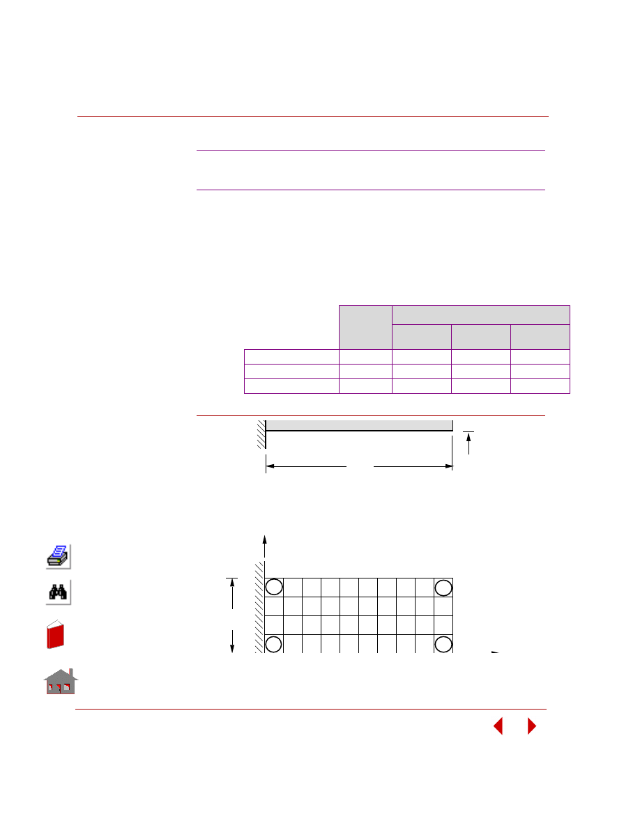
Chapter 2 Linear Static Analysis
2-66
COSMOSM Basic FEA System
TYPE:
Static analysis, shell elements (SHELL4, SHELL6).
PROBLEM:
Calculate reactions and deflections of a cantilever beam subject to a concentrated
load at tip.
Figure S42-1
S42A, S42B: Reactions and
Deflections of a Cantilever Beam
GIVEN:
COMPARISON OF RESULTS:
E
= 30E6 psi
h
= 1 in
L
= 10 in
W = 4 in
P
= 8 lb
Theory
COSMOSM
SHELL4
SHELL6
(Curved)
SHELL6
(Assembled)
Tip Deflection (Node 33) -2.667 x 10
-4
-2.667 x 10
-4
-2.683 x 10
-4
-2.667 x 10
-4
Total Force Reaction
8 lb
8 lb
8 lb
8 lb
Total Moment Reaction
-80 lb-in
-80 lb-in
-80 lb-in
-80 lb-in
L
1
31
40
10
45
55
33
11
W
Problem Sketch
Y
X
h
In
de
x
In
de
x
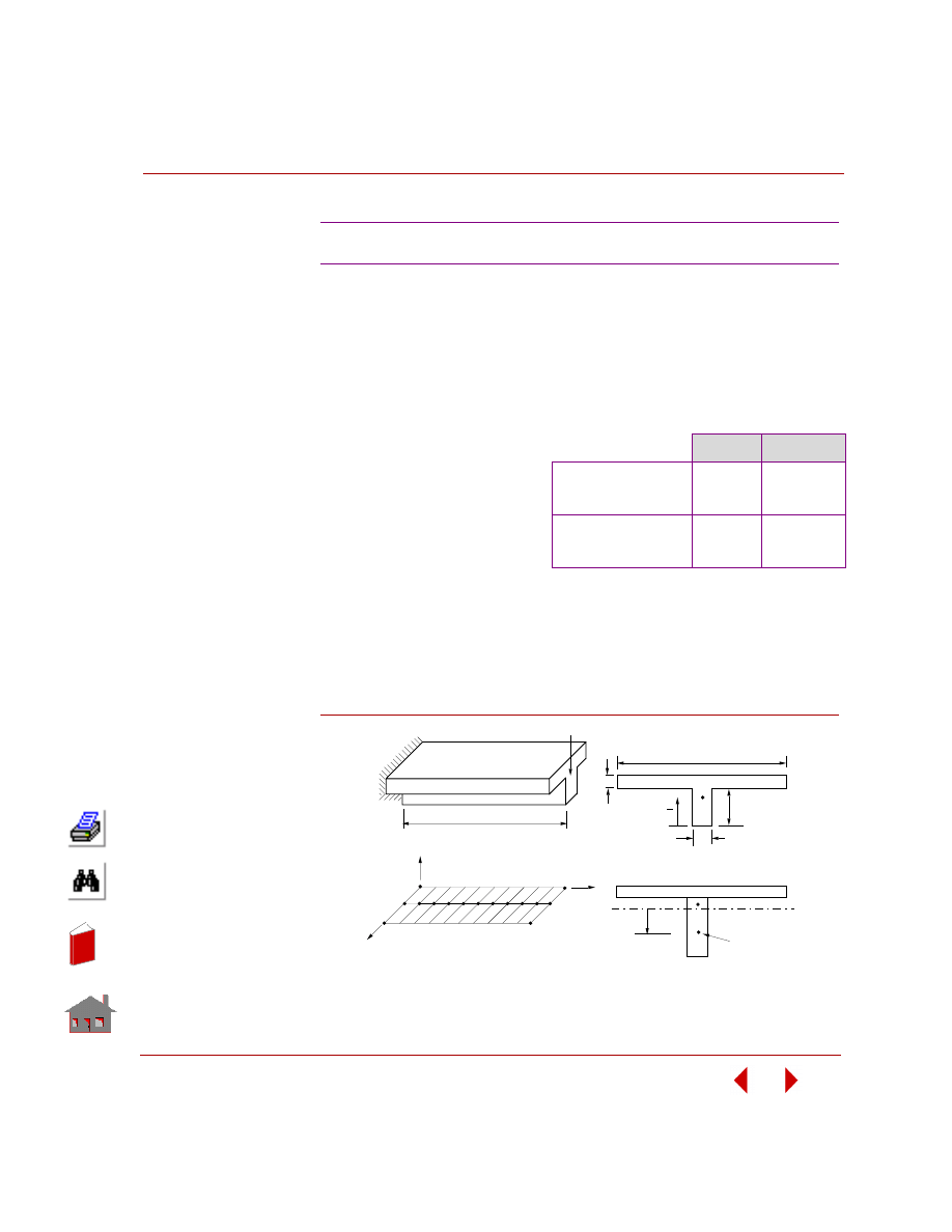
COSMOSM Basic FEA System
2-67
Part 2 Verification Problems
TYPE:
Static analysis, shell element, beam element with offset (SHELL4L, BEAM3D).
PROBLEM:
Calculate the deflections and stresses of a cantilever T beam subjected to a
concentrated load at the free end.
Figure S43-1
S43: Bending of a T Section Beam
GIVEN:
COMPARISON OF RESULTS:
L
= 2000 in
y
= 49 in
I
= 480833.33 in
4
E
= 10E10 psi
Dy = -24 in
Theory
COSMOSM
Free End (at Node 12)
Y-Displacement (in)
θ
z
- Rotation
-5.546E-6
-4.159E-9
-5.588E-6
-4.161E-9
Clamped End
σ
x
top (psi)
σ
x
bottom (psi)
4.57360
20.3813
4.377
21.302
ANALYTICAL SOLUTION:
δ = PL
3
/ 3EI
φ = PL
2
/ 2EI
σ = Mc / I
NOTE:
The maximum stress occurs in the beam. The
point at which stresses are calculated for
unsymmetric beams should be specified in the
real constant set (real constants 25 and 26).
200"
50"
10"
10"
L
P
SHELL4L
I
C.G. of
BEAM 3D
Element
DY
N.A.
y
Y
Z
X
23
12
1
33
Finite Element Model
22
11
Problem Sketch
CG
In
de
x
In
de
x
Chapter 2 Linear Static Analysis
2-68
COSMOSM Basic FEA System
TYPE:
Static analysis, shell elements (SHELL4), coupled points (file S44A) and/or
constraint equations (file S44B).
REFERENCE:
Timoshenko, S., “Strength of Materials, Part II, Advanced Theory and Problems,”
3rd Edition, D. Van Nostrand Co., Inc., New York, l956.
PROBLEM:
A circular plate with a center hole is built-in along the inner edge and unsupported
along the outer edge. The plate is subjected to bending by a moment M applied along
the outer edge. Determine the maximum deflection and the maximum slope of the
plate. In addition, deter-mine the moment M and the corresponding stress at the
center of the first and the last elements.
GIVEN:
CALCULATED INPUT:
M
1a
= 10 in-lb/in = 52.359 in lb/l0
° segment
MODELING HINTS:
Since the problem is axisymmetric, only a small sector of elements is needed. A
small angle
θ is used for approximating the circular boundary with a straight-side
element. A radial grid with nonuniform spacing (3:l) is used. The load is applied
equally to the outer nodes. Coupled nodes (CPDOF) and/or constraint equations
(CEQN) are used to ensure symmetry for S44A and S44B, respectively. Note that all
constraint and load commands are active in the cylindrical coordinate system.
S44A, S44B: Bending of a Circular
Plate with a Center Hole
E
= 30E6 psi
ν
= 0.3
h
= 0.25 in
b
= 10 in
a
= 30 in
M = 10 in lb/in
θ
= 10
°
In
de
x
In
de
x
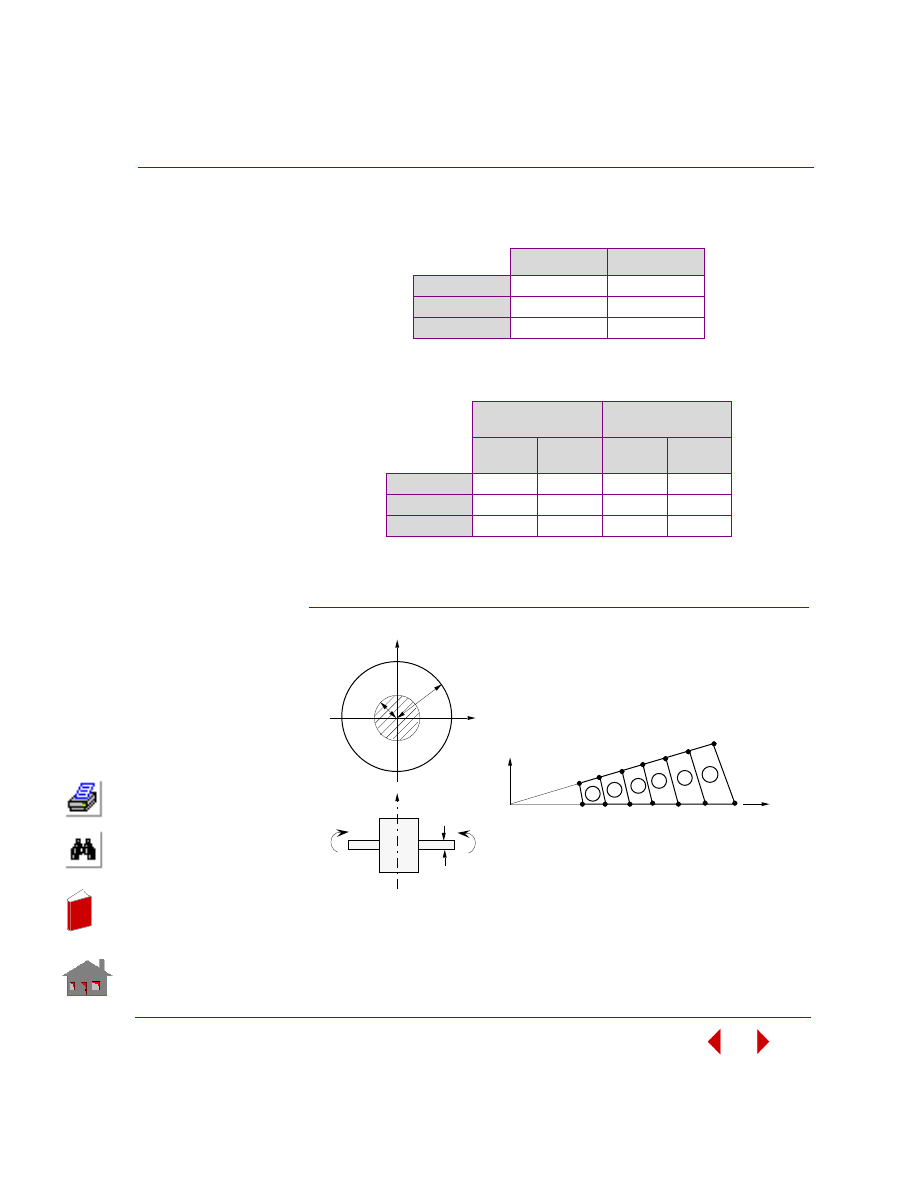
COSMOSM Basic FEA System
2-69
Part 2 Verification Problems
COMPARISON OF RESULTS
*
:
At the outer edge (node 14).
Figure S44-1
δ
z
, inch
θ
y
, rad
Theory
0.0490577
-0.0045089
COSMOSM
0.0492188
-0.0044562
Difference
0.3%
1.17%
*
The above results are tabulated for S44A.
Identical results will be obtained for S44B.
X = 10.86 inch
(First Element)
X = 27.2 inch
(Sixth Element)
Moment
in-lb/in
σ
r
, psi
Moment
in-lb/in
σ
r
, psi
Theory
-13.7
1319
-10.1
971.7
COSMOSM
-13.7
1313
-10.1
972.7
Difference
0%
0.45%
0%
0.10%
*
The above results are tabulated for S44A. Identical
results will be obtained for S44B.
M
M
h
Z
X
Y
a
b
Problem Sketch
8
14
13
12
11
10
9
7
6
5
4
3
2
1
1
2
3
4
5
6
θ
Y
X
Finite Element Model
)
In
de
x
In
de
x
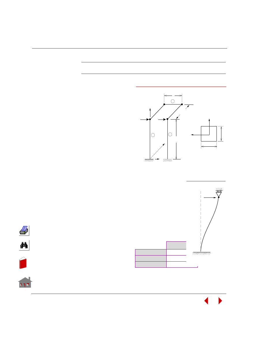
Chapter 2 Linear Static Analysis
2-70
COSMOSM Basic FEA System
TYPE:
Static analysis, beam elements
(BEAM3D) and point-to-point
constraints (CPCNS
command).
REFERENCE:
Laursen H. I., “Structural
Analysis,” McGraw-Hill, l969.
PROBLEM:
Two vertical beams constitute
an eccentric portal frame with
the aid of 3 horizontal rigid
bars. Find the deformations
resulting from the horizontal
forces.
GIVEN:
h
= l in
S
= 2.5
W = l in
E = lE6 psi
L
= l0 in
P
= 1 lb
I
= l/l2 in
4
(about y and z axis)
MODELING HINT:
Point-to-point constraint elements are used (i.e., points 2-
3, 3-4 and 4-5) to ensure the frame 2-3 - 4-5 is rigid when
the horizontal forces are loaded. Each of the beams (l)
and (2) will deform as shown:
COMPARISON OF RESULTS:
S45: Eccentric Frame
Deflection
along X-axis
at points A
and B:
δ
x
(inch)
Theory
1.0000E-3
COSMOSM
1.0104E-3
Difference
1%
x
y
L
w
h
y
x
P
z
1
3
2
L
Cross Section
Problem Sketch and Finite Element Model
s
P
B
A
Figure S45-1
Figure S45-2
P,
δ
Deflected S hape
In
de
x
In
de
x

COSMOSM Basic FEA System
2-71
Part 2 Verification Problems
TYPE:
Static analysis, plane stress elements (PLANE2D), beam elements (BEAM2D),
shell elements (SHELL9) and constraint elements.
PROBLEM:
Calculate the maximum deflection and the maximum rotation of a cantilever beam
loaded by a shear force at the free end.
GIVEN:
MODELING HINTS: Continuum-to-Structure Constraint
Problem 1 (S46):
The plane stress elements are defined by nodes 1 through 12. The beam element is
defined by nodes 13 and 14. Each plane stress element is theoretically equivalent to
a beam element where I = 1/12 in
4
. Node 14 is attached to line 11-12, so displace-
ments and rotations are constrained to be compatible.
Problem 2 (S46A):
Two groups of PLANE2D, plane stress, 8-node elements are coupled together as
shown in Figure S46–2 where the geometry and material properties are the same as
those in Problem 1. The focus of interest in on the continuum-to-continuum
constraint and the location of the primary point which is no longer located at the
middle of the 3-point curve, but at any arbitrary position.
Problem 3 (S46B):
Two groups of SHELL9 elements are coupled together as shown in Figure S46–3
where the geometry and material properties are the same as those in Problem 1 and
2. The primary deformation is located in the x-y plane. This problem is provided to
verify the accuracy of the structure-to-structure constraint.
ANALYTICAL SOLUTION:
δ
y
= -pL
3
/ 3EI
θ
x
= -pL
2
/ 2EI
S46, S46A, S46B: Bending of a Cantilever Beam
h
= 1 in
L
= 10 in
I
= 1/12 in
4
E
= lE6 psi
ν
= 0.3
p
= -1 lb
In
de
x
In
de
x
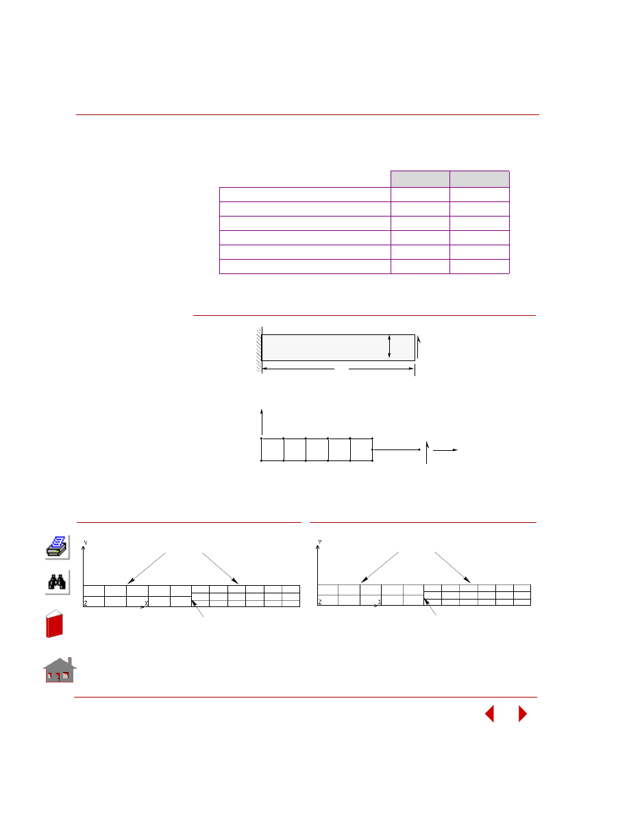
Chapter 2 Linear Static Analysis
2-72
COSMOSM Basic FEA System
COMPARISON OF RESULTS:
At the free end:
Figure S46-1
δ
y
inch
θ
z
rad
Theory
-4.000E-3
-6.000E-4
Beam Element
-4.000E-3
-6.000E-4
Plane Stress Element
-4.006E-3
-6.000E-4
Beam/Plane Stress Element (S46)
-4.008E-3
-6.000E-4
Plane Stress/Plane Stress Element (S46A)
-4.009E-3
-5.985E-4
*
SHELL9/SHELL9 Element (S46B)
-4.014E-3
-5.990E-4
*
*
Computed using displacements at the free end.
P
E,I
L
h
Problem Sketch
1
3
2
4
12
13
11
14
x
P
Y
Finite Element Model
Figure S46-2
Plane Stress (PLANE2D) Elements
Point-to-Line Constraints
Finite Element Model - 2
Shell (SHELL9) elements
Point-to-line Constraints
Finite Element Model - 3
Figure S46-3
In
de
x
In
de
x

COSMOSM Basic FEA System
2-73
Part 2 Verification Problems
TYPE:
Static analysis, SOLID elements, TETRA10 elements, BEAM elements, and point-
to-surface constraint elements (attachment).
PROBLEM:
Calculate the maximum deflection and the maximum rotation 0 of a cantilever beam
loaded by a shear force at the free end.
GIVEN:
MODELING HINTS: Continuum-to-Structure Constraint
Problem 1 (S47):
The solid elements are defined by nodes 1 through 24. The beam element is defined
by nodes 25 and 26. Each solid element is theoretically equivalent to a beam element
where I = 1/12 in
4
about y and z axes. Node 25 is attached to surface 21-22-24-23,
so displacements and rotations are constrained to be compatible.
Problem 2 (S47A):
Two groups of SOLID 20-node elements are coupled together as shown in Figure
S47-2 where the geometry and material properties are the same as those in Problem
1. The focus of interest is on the continuum-to-continuum constraint and the location
of the primary point which is no longer located at the middle of the 8-point surface,
but at any arbitrary position.
Problem 3 (S47B):
Two groups of TETRA10 elements are coupled together as shown in Figure S47-3
where the geometry and material properties are the same as those in Problem 1 and
2. This problem is provided to verify the accuracy of the continuum-to-continuum
constraint with the primary point located at any arbitrary position of a 6-node
surface.
ANALYTICAL SOLUTION:
δ = -PL
3
/ 3EI
θ = -PL
2
/ 2EI
S47, S47A, S47B: Bending of a Cantilever Beam
h
= 1 in
w = 1 in
L
= l0 in
I = 1/12 in
4
(about y and z axes)
E
= 1E6 psi
ν
= 0
p
= 1 lb
In
de
x
In
de
x
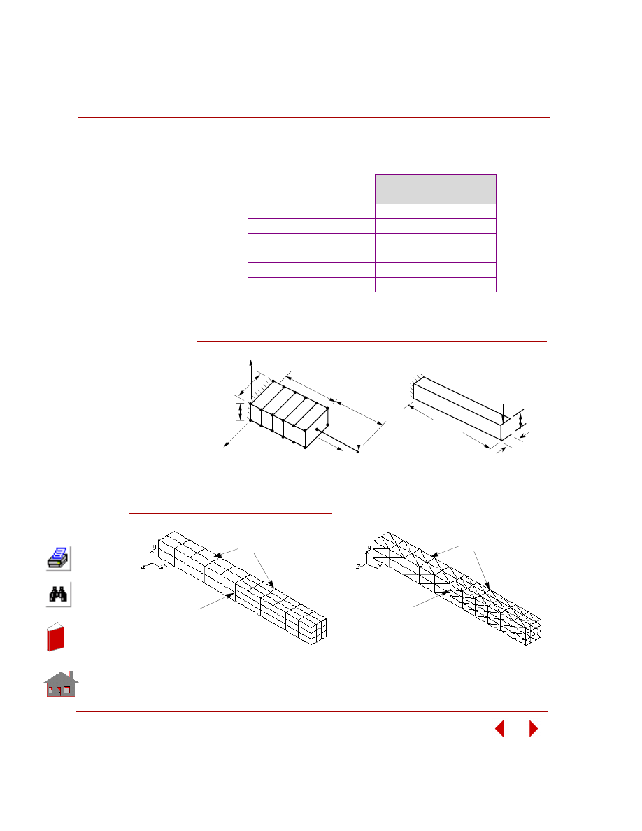
Chapter 2 Linear Static Analysis
2-74
COSMOSM Basic FEA System
COMPARISON OF RESULTS:
At the free end.
Figure S47-1
Deflection
δ
inch
Rotation
θ
rad
Theory
-4.000E-3
-6.000E-4
Beam Element
-4.000E-3
-6.000E-4
Plane Stress Element
-4.010E-3
-6.000E-4
Beam/Solid Element (S47)
-4.005E-3
-6.000E-4
Solid/Solid Element (S47A)
-3.986E-3
-5.962E-4 *
Tetra10/Tetra10 Element (S47B)
-3.969E-3
-5.950E-4 *
*
Computed using displacements at the free end.
21
h
Y
Z
X
P
1
3
23
24
26
22
2
6
25
5
L/2
w
Finite Element Model – 1
L/2
7
1
Problem Sketch
P
w
h
L
Figure S47-2
SOLID Elements
Point-to-surface Constraints
Finite Element Model - 2
Figure S47-3
TETRA10 Elements
Point-to-surface Constraints
Finite Element Model - 3
In
de
x
In
de
x
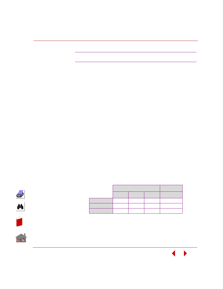
COSMOSM Basic FEA System
2-75
Part 2 Verification Problems
TYPE:
Static analysis, axisymmetric elements (PLANE2D).
REFERENCE:
Brenkert, Jr., K., “Elementary Theoretical Fluid Mechanics,” John Wiley and Sons,
Inc., New York, l960.
PROBLEM:
A large cylindrical tank is partially filled with an incompressible liquid. The tank
rotates at a constant angular velocity about its vertical axis as shown. Determine the
elevation of the liquid surface relative to the center (lowest) elevation for various
radial positions. Also, determine the pressure p in the fluid near the bottom corner
of the tank.
GIVEN:
COMPARISON OF RESULTS:
S48: Rotation of a Tank of Fluid (PLANE2D Fluid)
w = l rad/sec
r =
48
in
h
= 20 in
ρ
= 0.9345E-4 lb-sec
2
/in
4
g
= 386.4 in/sec
2
b
= 30E4 psi
Where:
b
= bulk modulus
g
= acceleration due to gravity
ρ = density
Displacements
*
δ
y
inch
Pressure (psi)
Node 4
Node 7
Node 11
Element 60
Theory
-1.86335
0
+1.86335
-0.74248
COSMOSM
*
-1.8627
0
+1.8627
-0.74250
Difference
0.036%
0%
0.03%
0.003%
*
After subtracting from the displacement at Node 1 (-1.4798 in)
In
de
x
In
de
x
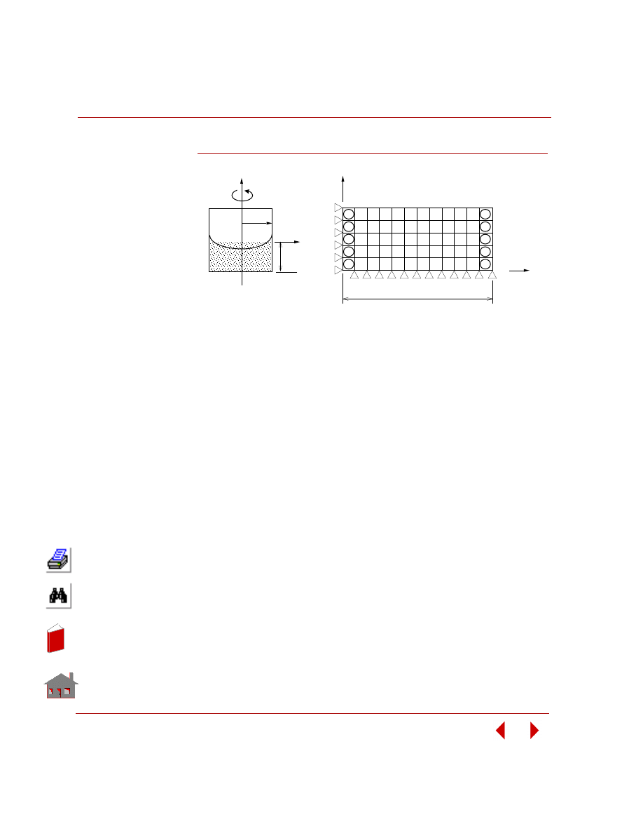
Chapter 2 Linear Static Analysis
2-76
COSMOSM Basic FEA System
Figure S48-1
2
3
4
5
6
7
8
9
10 11 12 13
1
14
27
40
53
66
1
13
25
37
49
12
24
36
48
60
26
39
52
65
78
r
Finite Element Model
Problem
Sketch
h
r
Y
ω
X
Y
X
In
de
x
In
de
x
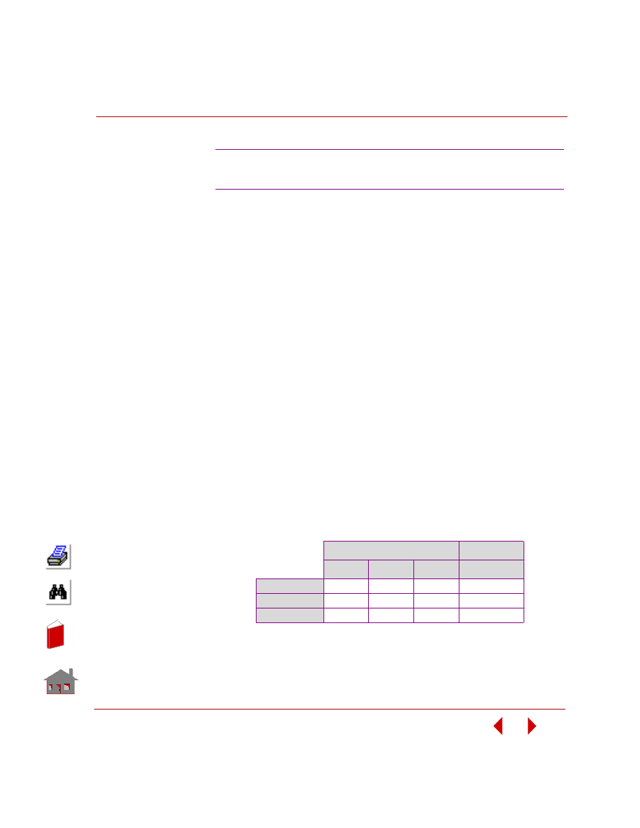
COSMOSM Basic FEA System
2-77
Part 2 Verification Problems
TYPE:
Static analysis plane strain (PLANE2D) or SOLID elements.
REFERENCE:
Brenkert, K., Jr., “
Elementary
Theoretical Fluid Mechanics,” John Wiley and Sons,
Inc., New York, l980.
PROBLEM:
Large rectangular tank is partially filled with an incompressible liquid. The tank has
a constant acceleration to the right, as shown. Determine the elevation of the liquid
surface relative to the zero acceleration elevation for various Y-axis positions. Also,
determine the slope of the surface and the pressure p in the fluid near the bottom
right corner of the tank.
GIVEN:
COMPARISON OF RESULTS:
S49A, S49B: Acceleration of a Tank
of Fluid (PLANE2D Fluid)
a
= 45 in/sec
2
b
= 48 in
h
= 20 in
g
= 386.4 in/sec
2
p
= 30E4 psi
ρ
= 0.9345E-4 lb-sec
2
/in
4
Where:
b
= bulk modulus
g
= acceleration due to gravity
ρ
= density
Displacements
δ
y
inch
Pressure (psi)
Node 3
Node 7
Node 11
Element 60
Theory
-1.86335
0
+1.86335
0.74248
COSMOSM
-1.8627
0
+1.8627
0.7425
Difference
0.036%
0%
0.03%
0.03%
In
de
x
In
de
x
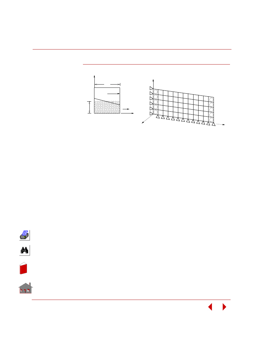
Chapter 2 Linear Static Analysis
2-78
COSMOSM Basic FEA System
Figure S49A-1
Problem Sketch
r
Y
X
Finite Element Model
(Use PLANE2D Elements)
Z
Y
X
b
a
h
α
1
13
25
37
49
12
24
36
48
60
1
14
27
40
53
66
26
39
52
65
78
2
3
4
6
7
8
9 10 11 12
5
13
In
de
x
In
de
x
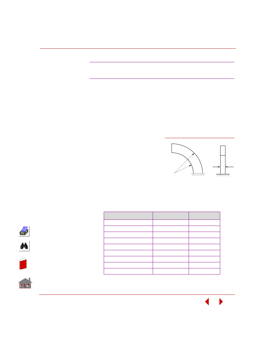
COSMOSM Basic FEA System
2-79
Part 2 Verification Problems
TYPE:
Static analysis, multi-field elements (4-node PLANE2D, 8-node PLANE2D,
SHELL4T, 6-node TRIANG, 8-node SOLID, 20-node SOLID, TETRA4R and
SHELL6 elements).
REFERENCE:
Roark, R. J., “Formulas for Stress and Strain,” 4th Edition, McGraw-Hill Book Co.,
New York, l965, pp. 166.
PROBLEM:
A curved beam is clamped at one
end and subjected to a shear force
P at the other end. Determine the
deflection at the free end.
GIVEN:
COMPARISON OF RESULTS:
Deflections at free end by theoretical solution is equal to 0.08854 in
S50A, S50B, S50C, S50D, S50F, S50G,
S50H, S50I: Deflection of a Curved Beam
E
= 10E6 psi
ν
= 0.25
R
l
= 4.12 in
R
2
= 4.32 in
t
= 0.1 in
p
= 1 lb
Element
COSMOSM
δ
y
in
2
Difference (%)
PLANE2D (4-Node) (S50A)
0.08761
1.05%
PLANE2D (8-Node) (S50B)
0.08850
0%
SHELL4T (S50C)
0.08827
0.26%
TRIANG (6-Node) (S50D)
0.07049
11.6%
TETRA4R (4-Node) (S50H)
0.08785
0.8%
SOLID (8-Node) (S50F)
0.08726
1.45%
SOLID (20-Node) (S50G)
0.08848
0.07%
SHELL6 (Curved) (S50I)
0.07498
15.32%
SHELL6 (Assembled) (S50I)
0.062679
29.2%
Figure S50-3
P
R
R
2
1
t
Problem Sketch
In
de
x
In
de
x
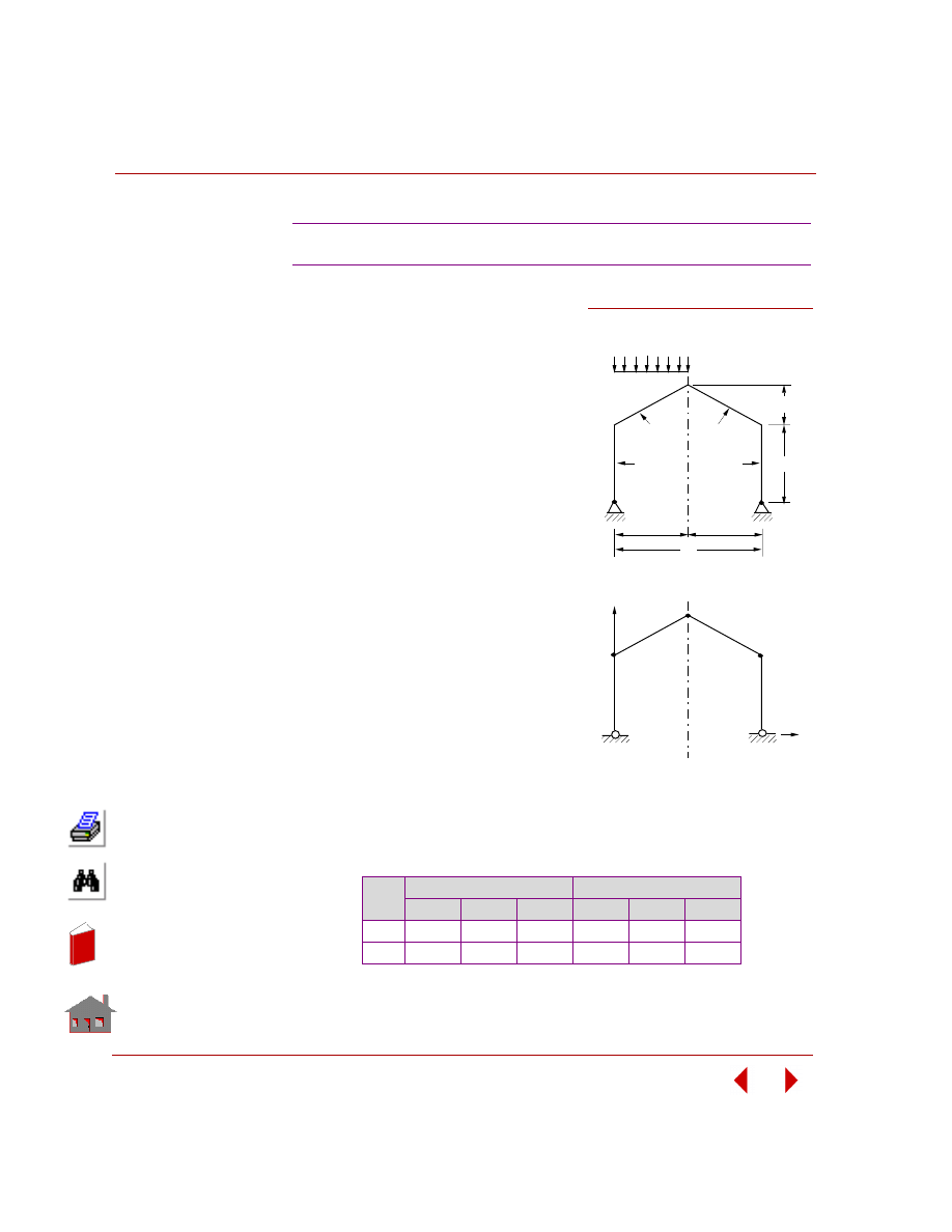
Chapter 2 Linear Static Analysis
2-80
COSMOSM Basic FEA System
TYPE:
Static analysis, beam elements (BEAM2D).
REFERENCE:
Valerian Leontovich, “Frames and Arches,”
McGraw-Hill Book Co., Inc., New York,
l959, pp. 68.
PROBLEM:
Determine the support reactions for frame
shown in the figure.
GIVEN:
L
= 16 ft
h
= 8 ft
E
= 4.32E6 lb/ft
2
f
= 6 ft
q
= 10 lb/ft
I
l2
= I
23
= I
34
= I
45
A
l2
= A
23
= A
34
= A
34
= A
45
Total Load = 4 lbs
MODELING HINTS:
Find load intensity along the frame from
W = (Total load) / q = 4 lb/ft
Then use beam loading commands to solve the problem
COMPARISON OF RESULTS:
Reactions (lb):
S51: Gable Frame with Hinged Supports
Node
No.
Theory
COSMOSM
FX
FY
MZ
FX
FY
MZ
1
4.44
30.00
0
4.40
30.00
0
5
-4.44
10.00
0
-4.40
10.00
0
Figure S51-1
L/2
L/2
Problem Sketch
I 2
I
1
W = q L/2
L
I 2
I
1
X
3
2
1
Finite Element Model
4
5
Y
h
f
In
de
x
In
de
x
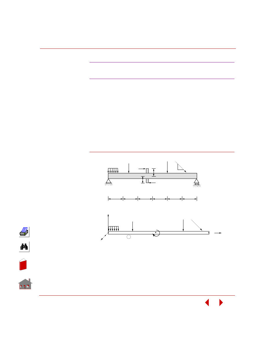
COSMOSM Basic FEA System
2-81
Part 2 Verification Problems
TYPE:
Static analysis, beam elements (BEAM2D).
REFERENCE:
Morris, C. H. and Wilbur, J. B., “Elementary Structural Analysis,” McGraw-Hill
Book Co., Inc., Second Edition, New York, l960, pp. 93-94.
PROBLEM:
Determine the support reactions for the simply supported beam with intermediate
forces and moments.
Figure S52-1
S52: Support Reactions for a Beam with
Intermediate Forces and Moments
75K
4K/ft
4
4
4
4
4
4
6K
2
6K
2
40K
30K
4K/ft
30K
Problem Sketch
40K 75K
1
3
24K ft
2
Finite Element Sketch
X
Z
Y
1
3
4
In
de
x
In
de
x
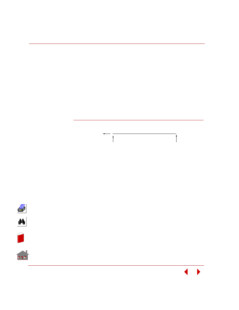
Chapter 2 Linear Static Analysis
2-82
COSMOSM Basic FEA System
GIVEN:
A = 0.3472 ft
2
I
y
= I
z
= 0.02009 ft
4
I
x
= 0.040l9 ft
4
E
= 4320 x l0
3
K/ft
2
NOTE:
The sign convention for the intermediate loads follows the local coordinate system
for the beam (defined by the I, J, K nodes).
COMPARISON OF RESULTS:
Figure S52-2
NOTE:
The results obtained with COSMOSM are compared with those given in reference.
The numbers shown in parenthesis are from COSMOSM.
R =
-45K (-45K)
1x
R = 57 K (57K)
1y
R = 89K (89K)
2y
In
de
x
In
de
x
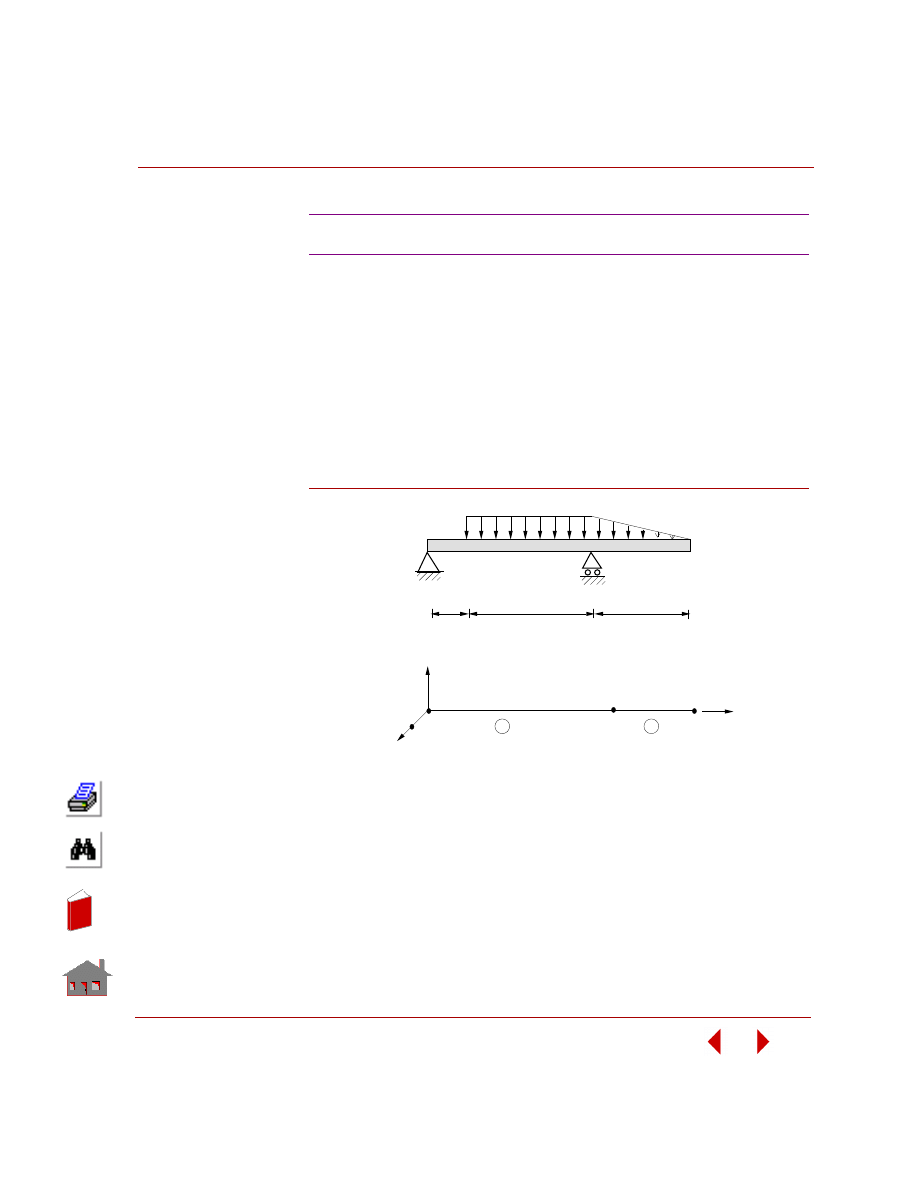
COSMOSM Basic FEA System
2-83
Part 2 Verification Problems
TYPE:
Static analysis, beam elements (BEAM2D).
REFERENCE:
Norris, C. H., and Wilbur, J. B., “Elementary Structural Analysis,” 2nd ed.,
McGraw-Hill Book Co., Inc., l960, pp. 99.
PROBLEM:
Find the reactions in the support and forces and moments in the beam.
Figure S53-1
GIVEN:
I
yy
= I
zz
= l ft
4
I
xx
= 2 ft
4
A = 3.464 ft
2
E
= 432 x l0
4
k/ft
2
S53: Beam Analysis with Intermediate Loads
4
Y
Z
X
1
2
3
Finite Element Model
1
2
2K/ft
4
16
10
Problem Sketch
In
de
x
In
de
x
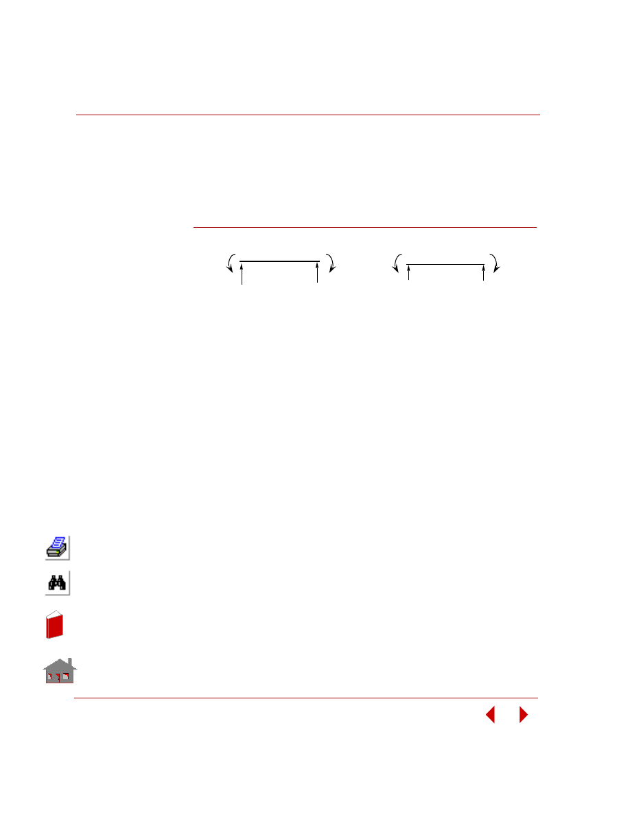
Chapter 2 Linear Static Analysis
2-84
COSMOSM Basic FEA System
NOTE:
The sign convention for intermediate loads, follows the local coordinate system, for
the beam (defined by I, J, K nodes).
COMPARISON OF RESULTS:
Figure S53-2
NOTE:
COSMOSM results are given in parentheses.
0
33.33 K.ft.
11.13 K
(11.13 K)
20.87 K
(20.87 K)
10.0 K
(10.0 K)
0.0 K
(0.0 K)
(-33.33 K.ft.)
(33.33 K.ft)
Node 1
Nod 2
Node 2
Node 3
Element 1
Element 2
Use the BEAMRESLIST (Results, List, Beam End Force)
command to list the results
0
In
de
x
In
de
x
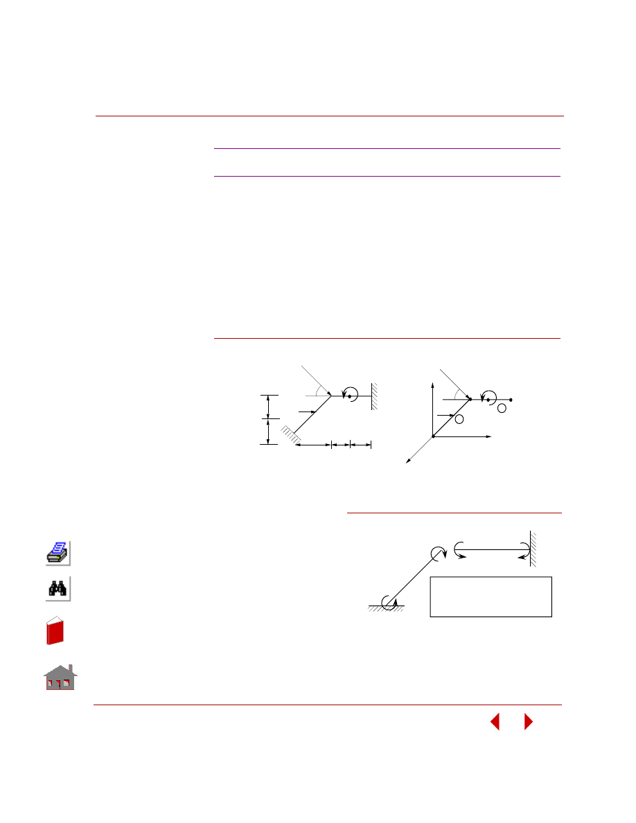
COSMOSM Basic FEA System
2-85
Part 2 Verification Problems
TYPE:
Static analysis, beam elements (BEAM2D).
REFERENCE:
Weaver, Jr., W., and Gere, J. M., “Matrix Analysis of Framed Structures,” 2nd ed.,
D. Van Nostrand Company, New York, l980. pp. 280, 486.
PROBLEM:
Find the deformations and forces in the plane frame subjected to intermediate forces
and moments.
Figure S54-1
GIVEN:
A
x
= 0.04 m
2
I
y
= I
z
= 2 x 10
3
m
4
I
x
= 4 x 10
3
m
4
E
= 200 x 10
6
KN/m
2
L
= 3m
P
1
= 30 x 2
(1/2)
KN
P
2
= 60 KN
M = 180 KN-m
S54: Analysis of a Plane Frame with Beam Loads
2
P
2
L/2
L/2
L/2
L/2
45
o
P
1
X
L
45
o
1
Y
P
1
2
Z
P
M
M
3
Problem Sketch
Finite Element Model
2
1
40.75*
40.75
+
4.747
+
5.44
+
* Results obtained from reference
+ Results obtained from COSMOS/M
Moments are in KNm units
Figure S54-2
In
de
x
In
de
x
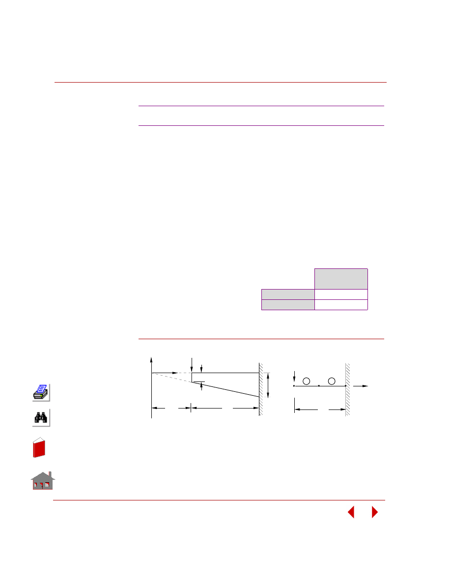
Chapter 2 Linear Static Analysis
2-86
COSMOSM Basic FEA System
TYPE:
Static analysis, beam element (BEAM3D).
REFERENCE:
Crandall, S. H., and Dahl, N. C., “An Introduction to the Mechanics of Solids,”
McGraw-Hill Book Co., Inc., New York, l959, pp. 342.
PROBLEM:
A cantilever beam of width b and length L has a depth which tapers uniformly form
d at the tip to 3d at the wall. It is loaded by a force P at the tip. Find the maximum
bending stress at x = L (midspan).
Figure S55-1
S55: Laterally Loaded Tapered Beam
GIVEN:
P
= 4000 lb
L
= 50 in
d
= 3 in
b
= 2 in
E
= 30E6 psi
COMPARISON OF RESULTS:
σ
x
(psi)
(at node 2)
Theory
8333
COSMOSM
8333
P
3d
d
x
y
L/2
L
Problem Sketch
1
2
3
Finite Element Model
x
P
2
1
L
In
de
x
In
de
x
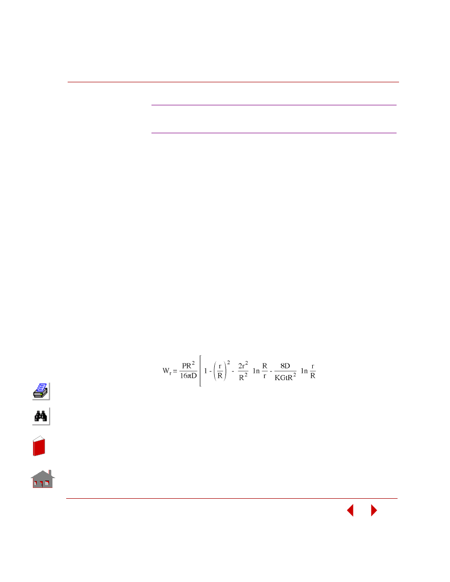
COSMOSM Basic FEA System
2-87
Part 2 Verification Problems
TYPE:
Static analysis, 9-node shell element (SHELL9).
REFERENCE:
Hughes, T. J. R., Taylor, R. L., and Kanoknukulchai, W. A., “Simple and Efficient
Finite Element for Plate Bending,” I.J.N.M.E., 11, 1529-1543, 1977.
PROBLEM:
A circular thick plate clamped at the boundary is subjected to a point load at its
center. (Shown in Figure S56-1).
Determine the transverse displacement along the radius r.
GIVEN:
E
= 1.09E6
ν = 0.3
t
= 2 (thickness) in
P
= 4 lb
R
= 5 in
ANALYTICAL SOLUTION:
Where:
D = Et
3
/ 12(1-
ν
2
)
G = E / 2 (1+
ν)
K = 0.8333 (shear correction factor)
S56: Circular Plate Under a Concentrated
Load (SHELL9 Element)
In
de
x
In
de
x
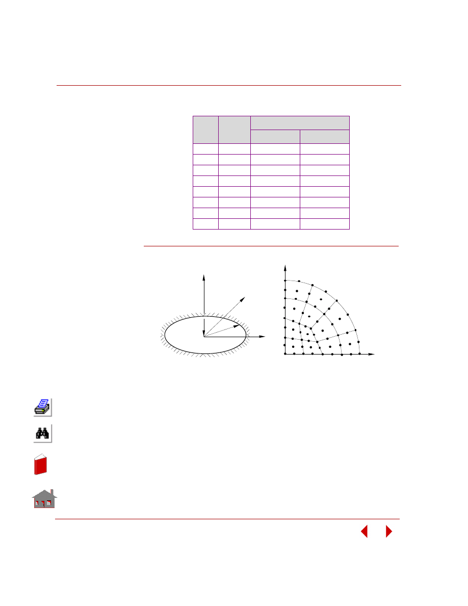
Chapter 2 Linear Static Analysis
2-88
COSMOSM Basic FEA System
COMPARISON OF RESULTS:
Figure S56-1
Node
r (in)
W
max
(in) x 10
-6
Analytical
COSMOSM
1
0.0
—
-6.469
2
.625
4.185
-4.242
3
1.250
3.1670
-3.166
4
1.875
2.3474
-2.349
5
2.500
1.6366
-1.637
6
3.125
1.0316
-1.033
7
3.750
0.5458
-0.5465
8
4.375
0.1962
-0.1968
y
x
1
2
3
4
5
6
7
8
9
Finite Element Model
(12 Elements)
Problem Sketch
P
z
y
x
R
In
de
x
In
de
x
COSMOSM Basic FEA System
2-89
Part 2 Verification Problems
TYPE:
Static analysis, 9-node shell element (SHELL9).
REFERENCE:
Dvorkin, E. N., and Bathe, K. J., “A Continue Mechanics Based Four Node Shell
Element for General Nonlinear Analysis,” Engineering Computations, 1, 77-78,
1984.
PROBLEM:
A cylindrical shell with both ends covered with rigid diaphragms which allow
displacement only in the axial direction of the cylinder is subjected to a concentrated
load on the center (shown in the figure below). Determine the radial deflection of
point P.
MODELING HINTS:
Due to symmetry, only one-eighth of the cylinder is modeled. To simulate the rigid
diaphragm, on the boundary of the cylinder with z = 0, no rotation along the axial
direction (z-axis) is allowed.
S57: Test of a Pinched Cylinder with
Diaphragm (SHELL9 Element)
GIVEN:
R
= 300 in
L
= 600 in
E
= 3E6 psi
ν
= 0.3
h
= 3 (thickness) in
P
= 1 lb
COMPARISON OF RESULTS
δ
x
(inch)
Theory
0.18248E-4
COSMOSM
0.17651E-4
In
de
x
In
de
x
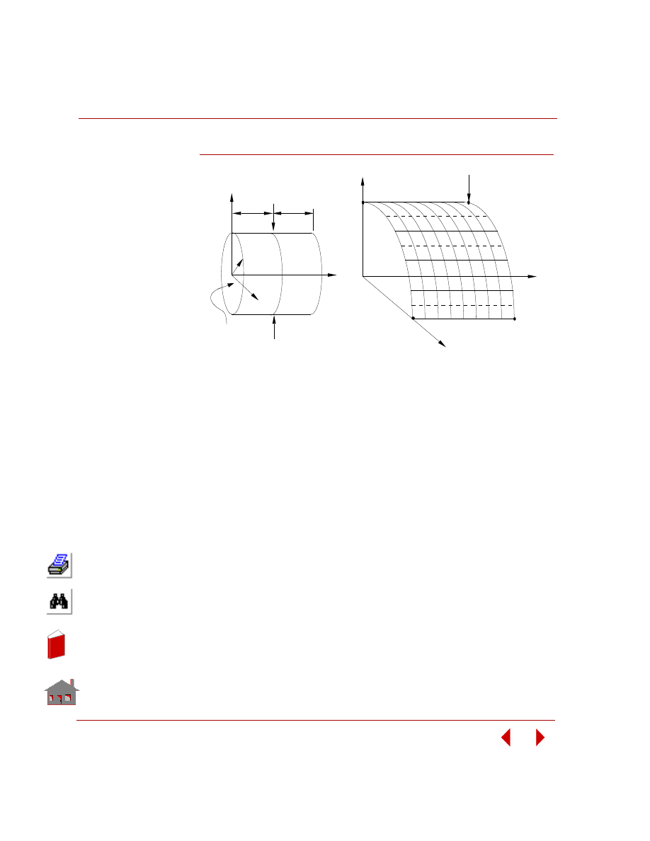
Chapter 2 Linear Static Analysis
2-90
COSMOSM Basic FEA System
Figure S57-1
X
Y
Z
Finite Element Model
(4 x 4)
P/4
73
1
9
81
z
x
y
Diaphragm
R
P
P
Problem Sketch
L/2
L/2
In
de
x
In
de
x
COSMOSM Basic FEA System
2-91
Part 2 Verification Problems
TYPE:
Static analysis, 9-node shell element (SHELL9), 4-node tetrahedral element
(TETRA4R).
REFERENCE:
MacNeal, R. H. and Harder, R. L., “A Proposed Standard Set of Problems to Test
Finite Element Accuracy,” F. E. in Analysis and Design, pp. 3-20, 1986.
PROBLEM:
A twisted beam is subjected to a concentrated load at the tip in the in-plane and out-
of-plane directions (shown in the figure below). Determine the deflections
coincident with the load.
GIVEN:
L
= 12 in
W = 1.1 in
h
= 0.32, 0.0032 (thickness) in
F
= 1 lb for h = 0.32 and 1e-6 lb for h=0.0032
E
= 29E6 psi
ν
= 0.22
COMPARISON OF RESULTS:
S58A, S58B, S58C: Deflection of a Twisted Beam
with Tip Force
Deflection in the direction of the
force
Thickness (in)
Force Direction
Theory
COSMOSM
h = 0.32 in
(S58A: SHELL9)
Force = 1.0 lb
In-Plane (Load case 1)
Out-of-Plane (Load Case 2)
0.5240E-2
0.1754E-2
0.5397E-2
0.1759E-2
h = 0.0032 in
(S58B: SHELL9)
Force=1e-6 lb
In-Plane (Load case 1)
Out-of-Plane (Load Case 2)
0.5256E-2
0.1794E-2
0.4704E-2
0.1255E-2
h = 0.32
(S58C: TETRA4R)
Force = 1.0 lb.
In-Plane (Load case 1)
Out-of-Plane (Load Case 2)
0.5240E-2
0.1754E-2
0.4967E-2
0.1600E-2
In
de
x
In
de
x
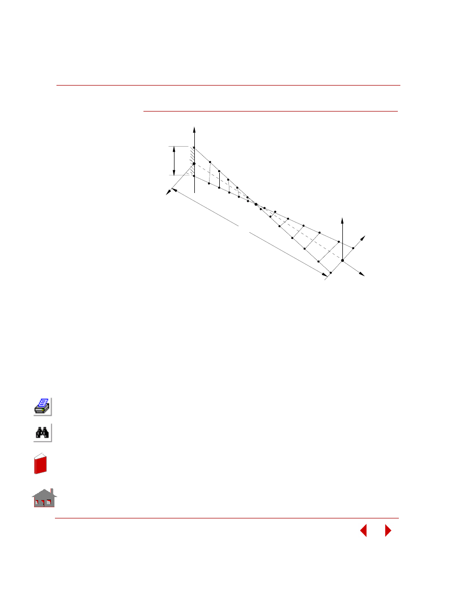
Chapter 2 Linear Static Analysis
2-92
COSMOSM Basic FEA System
Figure S58-1
L
x
y
w
F (out-of-plane)
z
Twist = 90
o
Problem Description and
Finite Element Mesh (1 x 6)
F (in-plane)
x
y
In
de
x
In
de
x
COSMOSM Basic FEA System
2-93
Part 2 Verification Problems
TYPE:
Static analysis, 4- and 9-node composite shell elements (SHELL4L, SHELL9L),
solid composite element (SOLIDL).
REFERENCE:
Chang, T. Y., and Sawamiphakdi, K., “Large Deformation Analysis of Laminated
Shells by Finite Element Method,” Computers and Structures, Vol. 13, pp. 331-340,
1981.
PROBLEM:
A square sandwich plate consisting of two identical facings and an aluminum
honeycomb core is subjected to uniform loading as shown in the figure below.
Determine the central deflection of the plate at point A.
MODELING HINTS:
Due to symmetry, one quarter of the plate is modeled. To ensure computational
stability, a small elastic modulus (E = 1.0E-12) for the core is used.
S59A, S59B, S59C: Sandwich Square Plate
Under Uniform Loading (SHELL9L)
GIVEN:
Facing:
E
= 10.5E6 ksi
ν
= 0.3
hf = 0.015 in (thickness)
Core:
E
= 0 ksi
a
= 25 in
G
xz
= G
yz
= 50 ksi
P
= 9.2311 psi
hc = 1 in (thickness)
COMPARISON OF RESULTS:
W
max
at the Center
Reference
SHELL4L (S59B)
SHELL9L (S59A)
SOLIDL (S59C)
0.846
0.868
0.849
COSMOSM
SHELL4L (S59B)
SHELL9L (S59A)
SOLIDL (S59C)
0.851
0.866
0.849
In
de
x
In
de
x
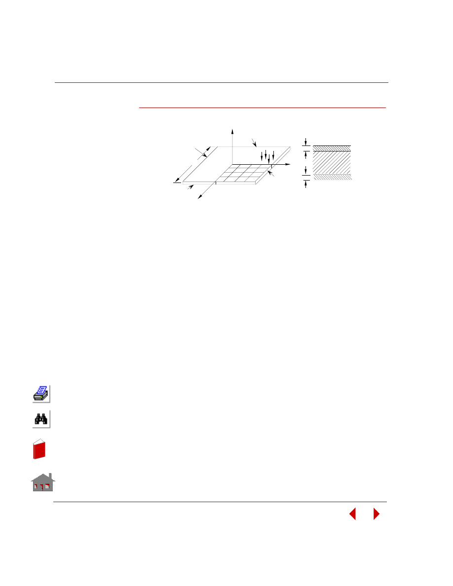
Chapter 2 Linear Static Analysis
2-94
COSMOSM Basic FEA System
Figure S59A-1
z
y
x
clamped
clamped
clamped
clamped
h
h
h
c
f
Problem Sketch and Finite Element Model
Cross Section
P
A
2a = 50
f
In
de
x
In
de
x

COSMOSM Basic FEA System
2-95
Part 2 Verification Problems
TYPE:
Static analysis, 9-node shell element (SHELL9).
REFERENCE:
Timoshenko, S. P. and Woinowsky-Krieger, S., “Theory of Plates and Shells,” 2nd
Ed., McGraw Hill, New York, 1959.
PROBLEM:
Determine the maximum deflection (at point A) of a clamped-clamped plate (shown
in the figure below) with uniform loading and modeled by a skewed mesh. Various
span-to-depth ratios are investigated.
GIVEN:
E
= 1E7 psi
ν
= 0.3
a
= 2 in
q
= 1 psi (0.01 psi is used for thickness 0.002)
t
= thickness = 0.2, 0.02, and 0.002 in
MODELING HINTS:
Due to symmetry, only one quarter of the plate is modeled.
ANALYTICAL SOLUTION:
U
a
= 0.00126 qa
4
/D
Where:
D = Et
3
/ 12(1 -
ν
2
)
S60: Clamped Square Plate Under
Uniform Loading
In
de
x
In
de
x
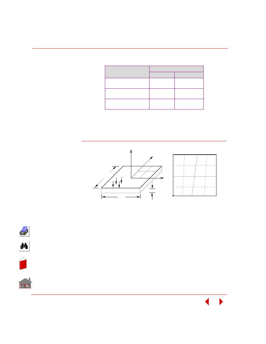
Chapter 2 Linear Static Analysis
2-96
COSMOSM Basic FEA System
COMPARISON OF RESULTS:
Figure S60-1
Span/Thickness Ratio
*
Deflection (inch)
Theory
COSMOSM
10
(q = 1.0 psi)
-2.7518E-6
-3.4758E-6
100
(q = 1.0 psi)
-2.7518E-3
-3.0649E-3
1,000
(q = 0.01 psi)
-2.7518E-2
-2.79259E-2
*
The input file provided (S60.GEO) is for a span/thick-
ness ratio of 10. You need to redefine the thickness for
other ratios using the RCONST command.
Better accuracy can be obtained with a finer mesh.
A
Finite Element Model
(2 x 2 Skew)
z
y
x
a
A
Problem Sketch
a
t
q
In
de
x
In
de
x
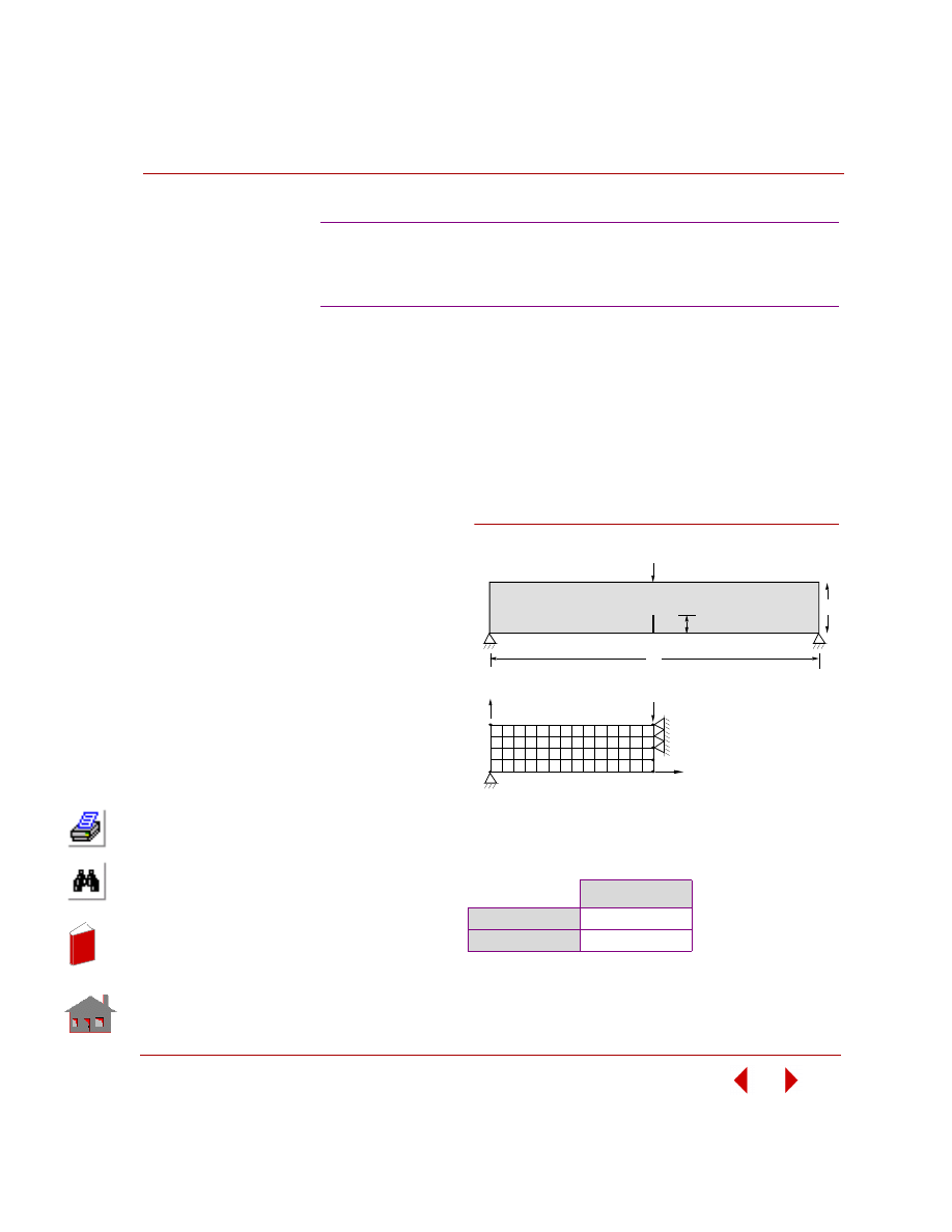
COSMOSM Basic FEA System
2-97
Part 2 Verification Problems
TYPE:
Static analysis, crack element, stress intensity factor, 8-node plane continuum
element (PLANE2D).
REFERENCE:
Brown, W. F.,
Jr., and Srawley, J. E., “Plane Strain Crack Toughness Testing of High
Strength Metallic Materials,” ASTM Special Technical Publication 410,
Philadelphia, PA, 1966.
PROBLEM:
Determine the stress
intensity factor of a
single-edge-cracked
bend specimen using
the crack element.
GIVEN:
E
= 30 x 10
6
psi
ν
= 0.3
Thickness = 1 in
a
= 2 in
b
= 4 in
L
= 32 in
P
= 1 lb
COMPARISON OF RESULTS:
S61: Single-Edge Cracked Bend Specimen,
Evaluation of Stress Intensity Factor
Using Crack Element
K
I
Theory
10.663
COSMOSM
9.855
L
P
a
Problem Sketch
Finite Element Model
Y
x
P/2
b
Figure S61-1
In
de
x
In
de
x
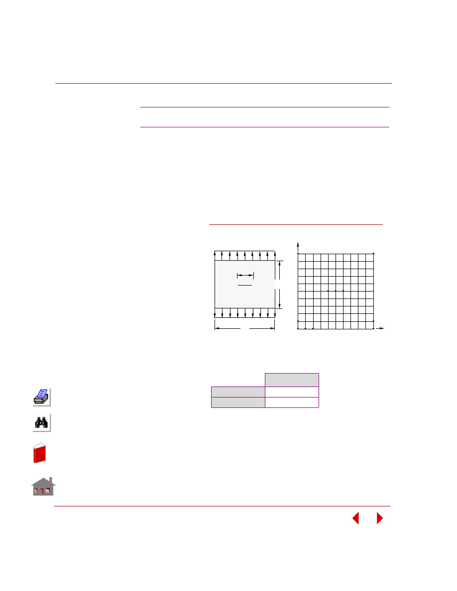
Chapter 2 Linear Static Analysis
2-98
COSMOSM Basic FEA System
TYPE:
Static analysis, crack stress intensity factor, 8-node plane continuum element
(PLANE2D).
REFERENCE:
Cook, Robert D., and Cartwright, D. J., “Compendium of Stress Intensity Factors,”
Her Majesty’s Stationary Office, London, 1976.
PROBLEM:
Determine the
stress intensity
factor of the center-
cracked plate.
GIVEN:
E
= 30x 10
6
psi
ν
= 0.3
Thickness = 1 in
W = 20 in
a
= 2 in
p
= 1 lb/in
COMPARISON OF RESULTS:
S62: Plate with Central Crack
K
I
Theory
2.5703
COSMOSM
2.668
2a
W
Y
X
Problem Sketch
Finite Element Model
p
p
W
Figure S62-1
In
de
x
In
de
x
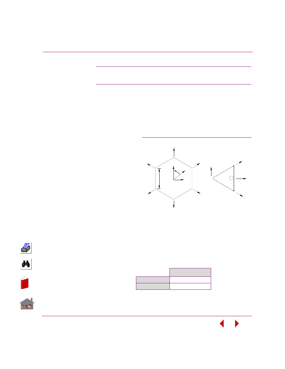
COSMOSM Basic FEA System
2-99
Part 2 Verification Problems
TYPE:
Static analysis, cyclic symmetry, truss elements (TRUSS2D).
REFERENCE:
Cook, Robert D., “Concepts and Applications of Finite Element Analysis.” 2nd
Edition, John Wiley & Sons, New York, 1981.
PROBLEM:
The pin-jointed plane
hexagon is loaded by
equal forces P, each
radial from center 0.
All lines are uniform
and identical. Find the
radial displacement of
a typical node.
GIVEN:
r
= 120 in
L
= l20 in
A = l0 in
2
P
= 3000 lb
E
= 30E6 psi
MODELING HINTS:
Taking advantage of the cyclic symmetry of the model and noting that the model
displaces radically the same amount at all six nodes, only one element is considered
with the radial degree of freedom coupled in the cylindrical coordinate system.
COMPARISON OF RESULTS:
Radial Displacement = 2PL/AE = (3000)(120)/(10)(30E6) = 0.0012 in
S63: Cyclic Symmetry Analysis
of a Hexagonal Frame
Radial Displacement
Theory
0.0012 in
COSMOSM
0.0012 in
P
P
P
P
P
P
Y
x
r
θ
B
D
A
C
O
Geometric Model
L
P
P
1
o
A
B
Finite Element Model
r
1
Y
x
2
Figure S63-1
In
de
x
In
de
x
Chapter 2 Linear Static Analysis
2-100
COSMOSM Basic FEA System
TYPE:
Static analysis, cyclic symmetry, 3-node triangular elements (TRIANG).
REFERENCE:
Cook, Robert D., “Concepts and Applications of Finite Element Analysis.” 2nd
Edition, John Wiley & Sons, New York, 1981.
PROBLEM:
A hexagonal shaped plate is loaded by a set of
radial forces as shown in the figure below.
Calculate the deformation of the structure at the
point where the load is applied. The plate is
considered as a plane stress problem and
modeled with 3-node triangular plane elements.
GIVEN:
R
= l0 in
t
= l in
P
= 3000 lb
E
= 30E6 psi
MODELING HINTS:
This plate is built by combining six sub-structures
at 60 degree angles relative to one another. Taking
advantage of the cyclic sub-structure may be considered for analysis. Note that for
the sub-structure shown, the displacements of nodes along A-A and B-B must be the
same in the radial directions. Therefore, these nodes will be coupled radially in the
cylindrical coordinate system. All degrees of freedom in the circumferential
direction will be fixed.
COMPARISON OF RESULTS:
The problem is solved for both the full structure and the sub-structure with the
displacements coming out identical for the corresponding nodes.
S64A, S64B: Cyclic Symmetry
Displacement at Point A
X-Displacement
Y-Displacement
Full Model (S64A)
-9.445E-5
-1.636E-4
Cyclic Part (S64B)
-9.450E-5
-1.637E-4
P
P
P
P
P
P
A
B
A
B
Full Structure
A
A
B
B
p
Sub-Structure
Figure S64-1
In
de
x
In
de
x
COSMOSM Basic FEA System
2-101
Part 2 Verification Problems
TYPE:
Static analysis, axisymmetric solid (PLANE2D) and fluid (PLANE2D) elements.
REFERENCE:
S. Timoshenko and S. Woinowsky-Kreiger, “Theory of Plates and Shells,” 2nd
Edition, McGraw Hill, New York, 1959, pp. 485-487.
PROBLEM:
A large cylindrical tank is filled with an incompressible liquid. The tank rotates at a
constant velocity about its vertical axis as shown. Determine the deflection of the
tank wall and the bending and shear stresses at the bottom of the tank wall.
S65: Fluid-Structure Interaction,
Rotation of a Tank of Fluid
GIVEN:
r
= 48 in
h
= 20 in
t
= 1 in
Fluid:
ρ
= 0.9345E-4 lb-sec
2
/in
4
b
= 30E4 psi
Tank:
E
= 3E7 psi
ν
= 0.3
ω = 1 rad/sec
g
= 386.4 in/sec
2
Where:
b
= Bulk modulus
g
= Accel. due to gravity
ρ
= Density
E
= Young's modulus
ν
= Poisson’s ratio
COMPARISON OF RESULTS:
Deflection in x-direction (10
-6
in)
Y (in)
Point
Theory
COSMOSM
20
16
12
8
4
0
A
B
C
D
E
F
7.381
19.544
27.805
27.161
13.604
0
8.269
18.854
26.870
26.578
13.700
0
Theory
COSMOSM
σ
yy,
(max), psi
52.24
40.34
Q
0
, lb/in
3.76
3.20
-
Note: Compatibility is imposed along the
direction normal to the interface using the
CPDOF command (LoadsBC, Structural,
Coupling, Define DOF Set).
In
de
x
In
de
x
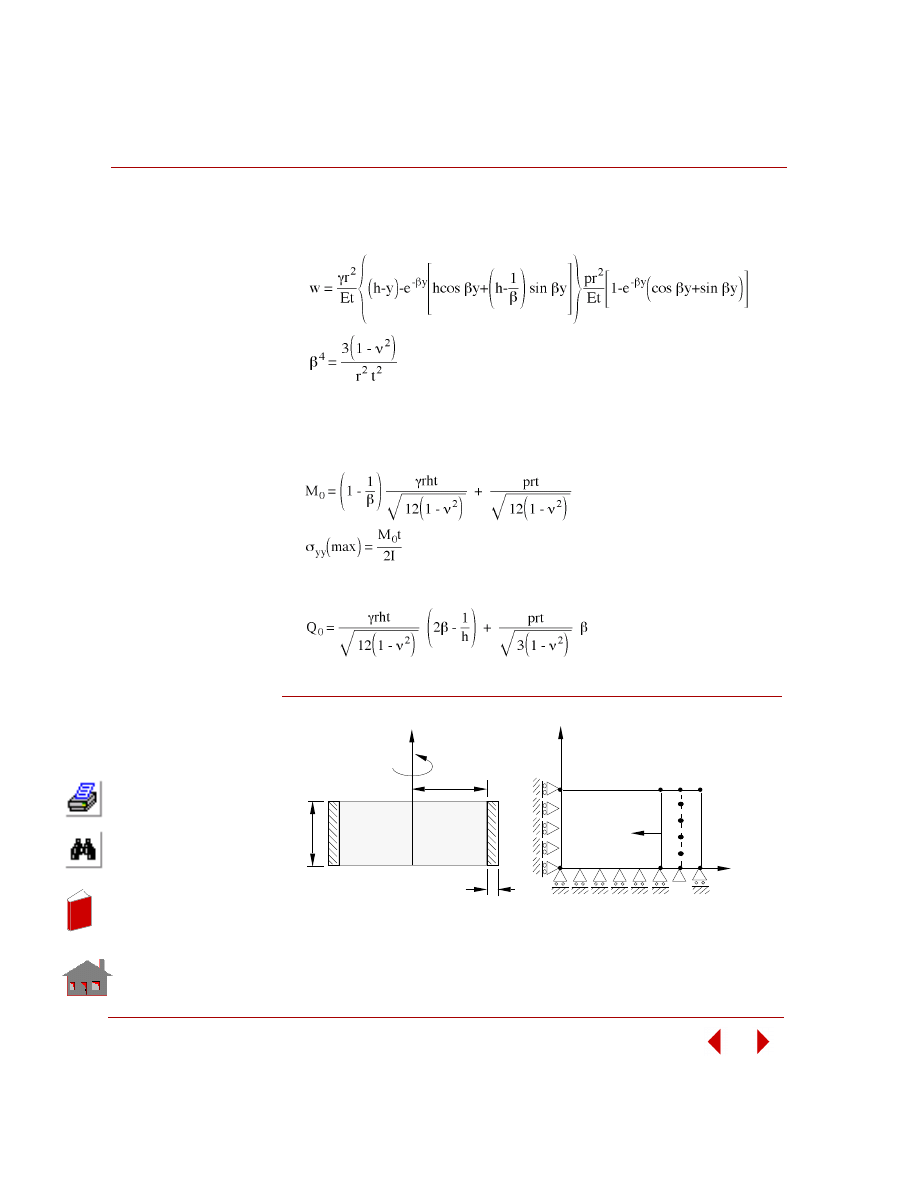
Chapter 2 Linear Static Analysis
2-102
COSMOSM Basic FEA System
ANALYTICAL SOLUTIONS:
1.
Deflection w(y):
λ = ρg
P = pressure applied on the tank wall due to an angular velocity
2.
End Moment M
0
:
3.
End Shear force Q
0
:
Figure S65-1
t
r
h
Liquid
y
ω
Problem Sketch
A
Interface
48 Elements
4 Elements
20
Elements
x
y
Finite Element Model
B
C
D
E
F
In
de
x
In
de
x
COSMOSM Basic FEA System
2-103
Part 2 Verification Problems
TYPE:
Static analysis, plane strain solid (PLANE2D) and plane fluid (PLANE2D)
elements.
REFERENCE:
Timoshenko, S. P., and Gere, James M., “Mechanics of Materials,” McGraw Hill,
New York, 1971, pp. 167-211.
PROBLEM:
A large rectangular tank is filled with an incompressible liquid. The tank has a
constant acceleration to the right, as shown. Determine the deflection of the tank
walls and the bending and shear stresses at the bottom of the right tank wall.
S66: Fluid-Structure Interaction,
Acceleration of a Tank of Fluid
GIVEN:
r = 48 in
h = 20 in
t = 1 in
Fluid:
ρ =
0.9345E-4
lb-sec
2
/in
4
b = 30E4 psi
Tank:
E= 3E7 psi
ν = 0.3
a = 45 in/sec
2
g = 386.4 in/sec
2
Where:
b = Bulk modulus
g = Gravity Accel.
ρ = Density
E= Young's modulus
ν = Poisson’s ratio
COMPARISON OF RESULTS:
Point Y (in)
W
R
(inch)
W
L
(inch)
Theory
COSMOSM
Theory
COSMOSM
A
B
C
D
E
F
20
16
12
8
4
0
2.137E-3
1.591E-3
1.054E-3
5.564E-4
1.662E-4
0
2.150E-3
1.602E-3
1.062E-3
5.619E-4
1.689E-5
0
6.667E-4
5.120E-4
3.552E-4
1.989E-4
6.348E-4
0
6.761E-4
5.193E-4
3.605E-4
2.024E-4
6.512E-5
0
Theory
COSMOSM
σ
yy
, (max), psi (at y = 0)
410.02
386.39
V
0
, lb/in (at y = 0)
9.24
8.84*
*This value is calculated by averaging TXY at the nodes
located at the bottom of the right wall giving half weight
to corner nodes.
-
Note: Compatibility is imposed along the direction
normal to the interface using the CPDOF command
(LoadsBC, Structural, Coupling, Define DOF Set).
In
de
x
In
de
x
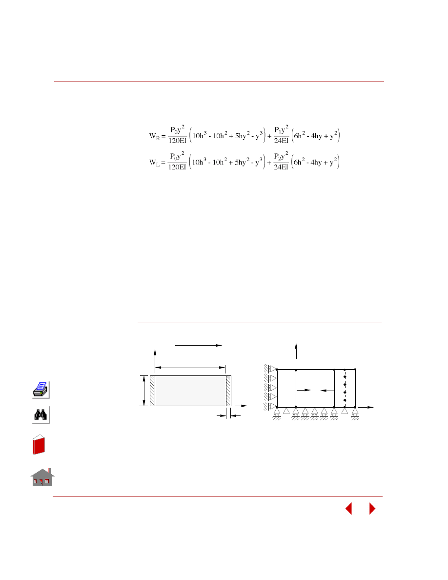
Chapter 2 Linear Static Analysis
2-104
COSMOSM Basic FEA System
ANALYTICAL SOLUTIONS:
1.
Deflections of the right wall W
R
(y) and the left wall W
L
(y):
Where:
p
0
= pgh
p
1
= pressure applied on the right wall due to acceleration
p
2
= pressure applied on the left wall due to acceleration
E
= E/(1-
ν
2
)
2.
End Moment M
0
M
0
= -EI d
2
W / dy
2
3.
End Shear Force V
0
V
0
=
τA
V
0
= -EI d
3
W / dy
3
Figure S66-1
x
b
h
Liquid
Problem Sketch
a = 45 in/sec
2
t
y
Interface
48
Elements
4
Elements
Finite Element Model
4
Elements
1235
1135
105
101
5
y
20
Elements
x
1139
1239
1
A
B
C
E
F
D
In
de
x
In
de
x
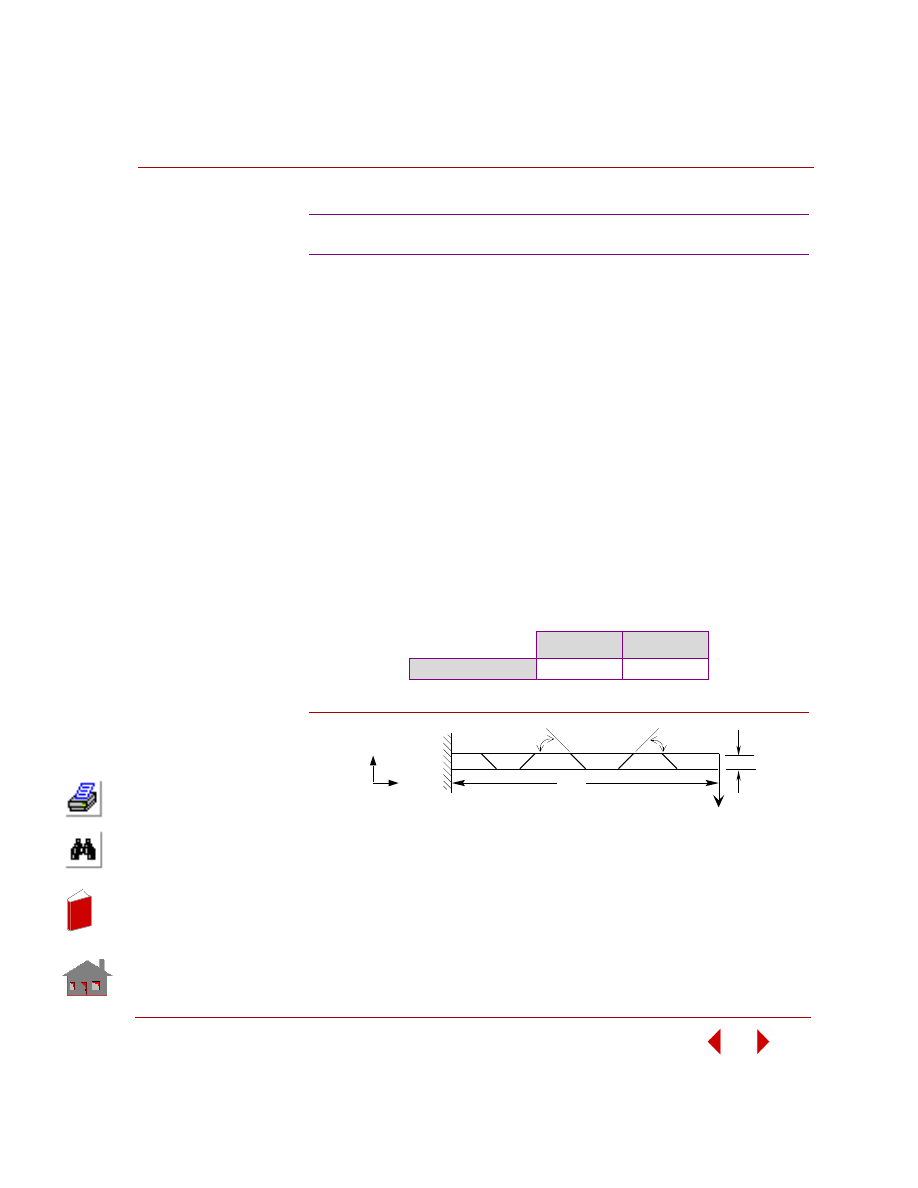
COSMOSM Basic FEA System
2-105
Part 2 Verification Problems
TYPE:
Static analysis, plane stress quadrilateral p-element (8-node PLANE2D) with the
polynomial order of shape functions equal to 5.
PROBLEM:
Calculate the maximum deflection of a cantilever beam loaded by a concentrated
end force.
GIVEN:
COMPARISON OF RESULTS:
Figure S67-1
S67: MacNeal-Harder Test
Geometric Properties:
h
= 0.2 in
t
= 0.1 in
L
= 6 in
I
= 2/3 x 10
-4
in
4
Material Properties:
E
= 1 x 10
7
psi
ν
= 0.3
Loading:
P
= 1 lb
Theory
COSMOSM
Tip Displacement
0.1081 in
0.10807 in
P
h
L
45
°
45
°
x
y
In
de
x
In
de
x
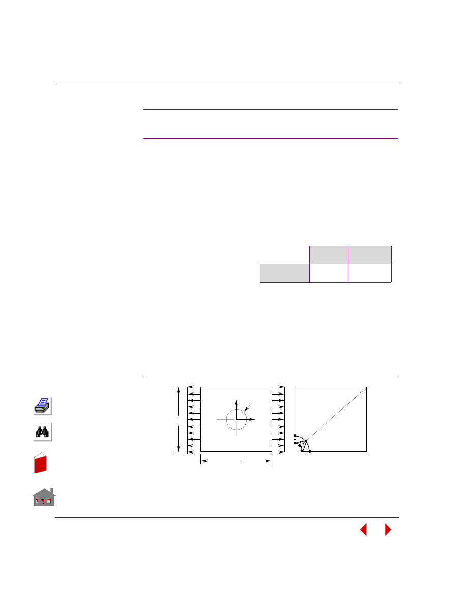
Chapter 2 Linear Static Analysis
2-106
COSMOSM Basic FEA System
TYPE:
Static analysis, plane stress quadrilateral (8-node PLANE2D) and triangular (6-node
TRIANG) p-elements with the polynomial order of shape functions equal to 5.
PROBLEM:
Calculate the maximum stress of a plate with a circular hole under a uniformly
distributed tension load.
Material Properties:
E
= 30 x 10
6
psi
ν
= 0.3
Loading:
p
= 1000 psi
Figure S68-1
S68: P-Method Solution of a Square
Plate with Hole
GIVEN:
COMPARISON OF RESULTS:
Geometric Properties:
L
= 12 in
d
= 1 in
t
= 1 in
Theory
COSMOSM
(PORD = 5)
Max. Stress in
X-Direction
3018
3058 psi
L
Y
X
d
P
P
•
•
•
•
•
•
•
•
L
In
de
x
In
de
x
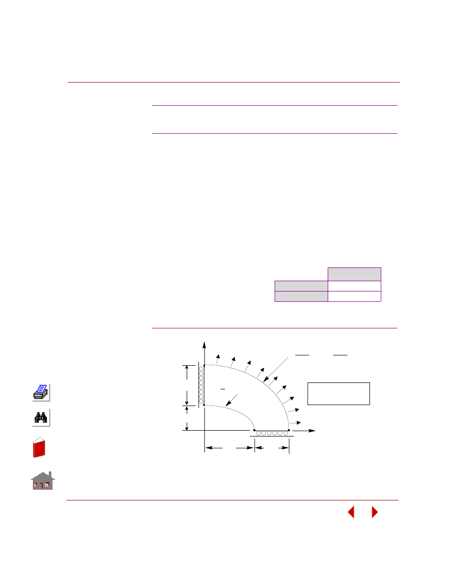
COSMOSM Basic FEA System
2-107
Part 2 Verification Problems
TYPE:
Static analysis, plane stress triangular p-element (6-node TRIANG).
REFERENCE:
Barlow, J., and Davis, G. A. O., “Selected FE Benchmarks in Structural and Thermal
Analysis,” NAFEMS Rept. FEBSTA, Rev. 1, October, 1986, Test No. LG1.
PROBLEM:
Calculate the stresses at point D of an elliptic membrane under a uniform outward
pressure.
Figure S69-1
S69: P-Method Analysis of an Elliptic
Membrane Under Pressure
GIVEN:
COMPARISON OF RESULTS
E = 210 x 10
3
MPa
ν = 0.3
t = 0.1
p = 10 MPa
σ
y
, at Point D
Theory
92.70
COSMOSM
93.72
1.0
1.75
x
y
2.0
1.25
D
2
y
2
x
2
All dimensions in meters
Thickness = 0.1
A
B
x
3.25
2
2
Y
2.75
= 1
C
+ = 1
(
(
(
(
(
)
)
)
)
)
+
+
+
+
+
(
(
(
(
(
)
)
)
)
)
(
(
(
(
(
)
)
)
)
)
In
de
x
In
de
x
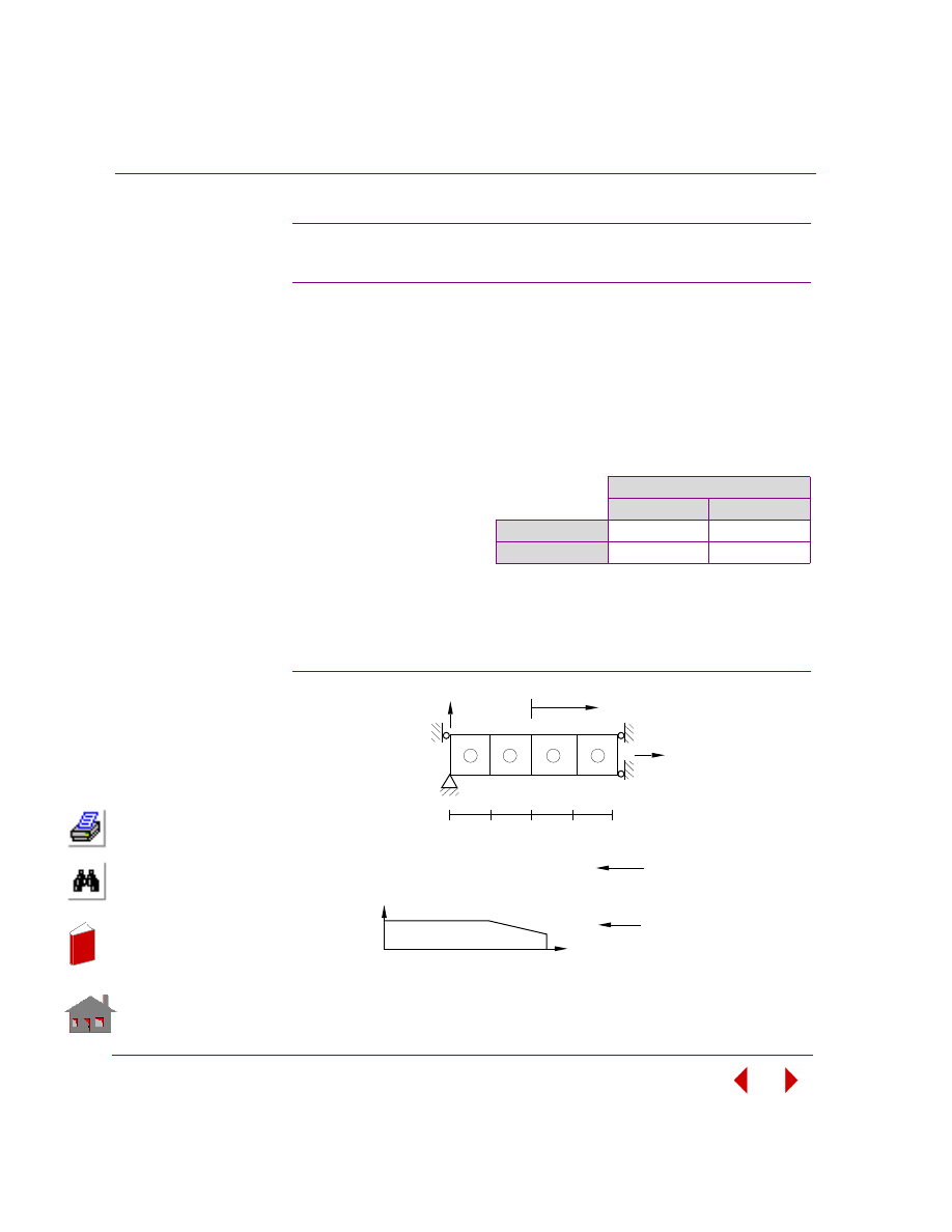
Chapter 2 Linear Static Analysis
2-108
COSMOSM Basic FEA System
TYPE:
Linear thermal stress analysis, plane continuum element (PLANE2D).
PROBLEM:
A flat plate consists of different material properties through its length. Determine the
deflections and thermal stresses in the plate due to uniform changes of temperature
equal to 100
° F and 200° F.
Figure S70-1
S70: Thermal Analysis with Temperature
Dependent Material
GIVEN:
t =
0.1
in
x
= 0.00001 in/in/
°F
ν
= 0
E
= 30,000 ksi
COMPARISON OF RESULTS:
σ
x
for All Elements
T = 100
°
F *
T = 200
°
F
Theory
-30 ksi
-48 ksi
COSMOSM
-30 ksi
-48 ksi
* The temperature in the input file corresponds to T =
200
°
F. You need to delete the applied temperature
using the NTNDEL command and apply tempera-
ture of 100
°
F using the NTND command.
E
(ksi)
30000
20000
150
200
Temperature
Elements 3 & 4
Elements 1 & 2
E = 30E3 ksi (CONSTANT)
Finite Element Model
X
1
2
3
4
5
6
8
9
10
7
Y
u
1"
1"
1"
1"
4
3
2
1
In
de
x
In
de
x
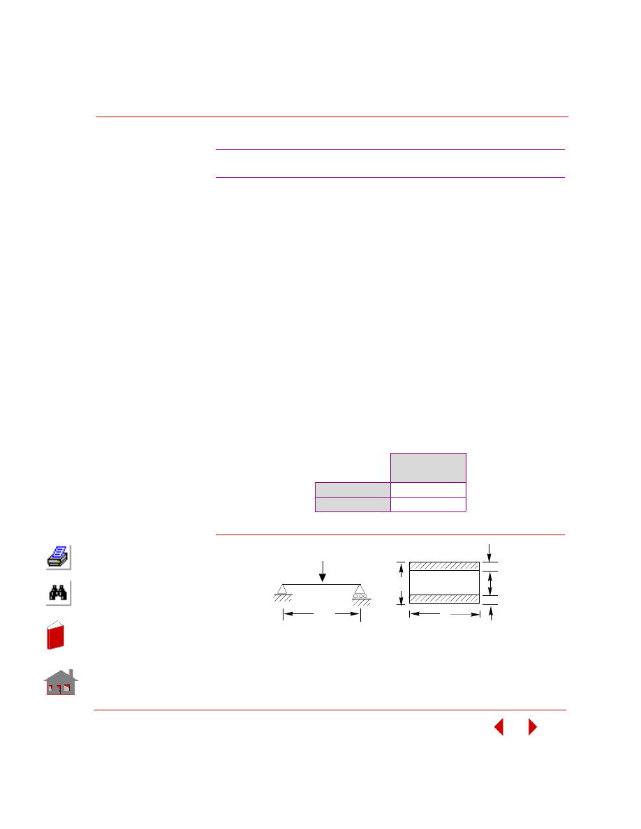
COSMOSM Basic FEA System
2-109
Part 2 Verification Problems
TYPE:
Static analysis, composite shell element (SHELL4L).
PROBLEM:
Determine the total deflection of the sandwich beam subjected to a concentrated
load.
GIVEN:
THEORY:
D = E
T
bt
3
/6 + E
T
btd
2
/2 + E
C
bc
3
/12 = 8.28 X 10
6
N.mm
2
δ = WL
3
/48D + WLc/4bd
2
G = 6.2902 + 3.986 = 10.276 mm
COMPARISON OF RESULTS:
Figure S71-1
S71: Sandwich Beam with Concentrated Load
E
t
= 7000 N/mm
2
t
= 3 mm
L
= 1000 mm
E
c
= 20 N/mm
2
c
= 25 mm
b
= 100 mm
G
c
= 5 N/mm
2
d
= 28 mm
W = 250 N
Midspan
Deflection (mm)
Theory
10.276
COSMOSM
10.323
d
W
b
c
t
t
L
In
de
x
In
de
x
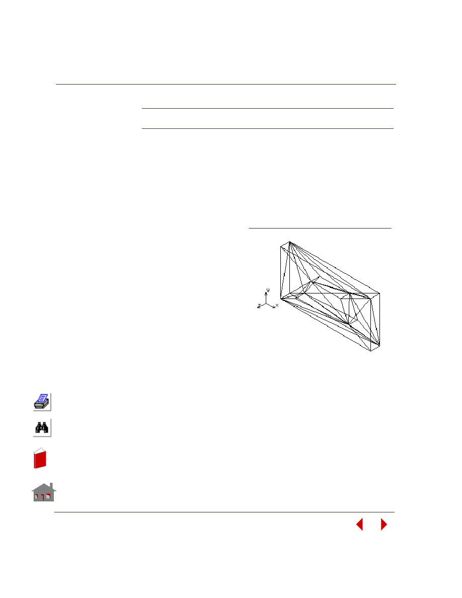
Chapter 2 Linear Static Analysis
2-110
COSMOSM Basic FEA System
TYPE:
Static analysis, tetrahedral elements (TETRA4, TETRA4R).
PROBLEM:
Constraint displacements at one end and prescribed displacements at the other end
of the plate to produce a constant stress state with
σ
x
= 0.1667E5 and
σ
y
=
σ
z
=
τ
xy
=
τ
yz
=
τ
zx
= 0.
Patch test model.
GIVEN:
Ex = 1E8
υ
= 0.25
δx = 0.4E-2
t
= 0.024
a
= 0.12
b =
0.24
RESULTS:
All the above elements pass
the patch test. The nodal
stresses show that
σ
x
=
0.1667E5 and
σ
y
=
σ
z
=
τ
xy
=
τ
yz
=
τ
zx
= 0.
S74: Constant Stress Patch Test (TETRA4R)
Figure S74-1
Finite Element Model for Patch Test
In
de
x
In
de
x
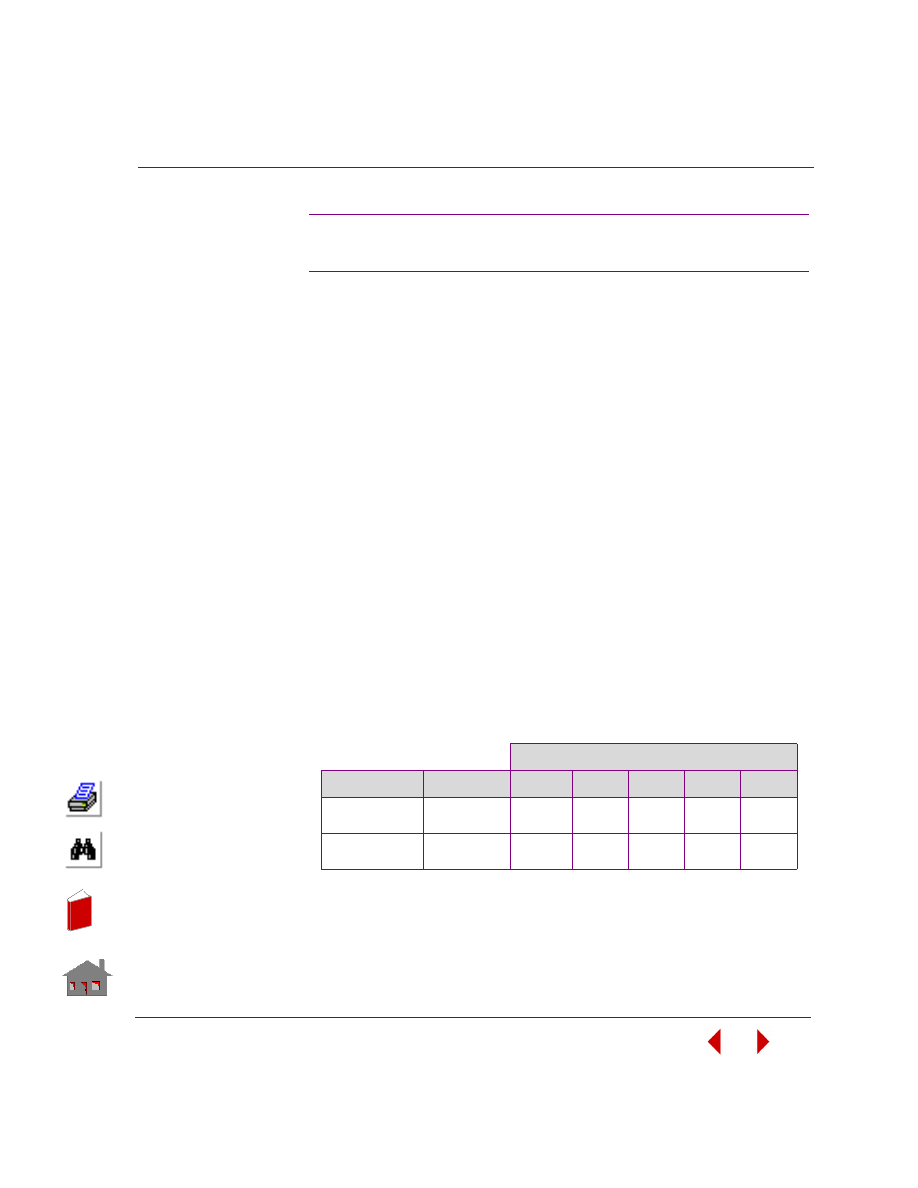
COSMOSM Basic FEA System
2-111
Part 2 Verification Problems
TYPE:
Linear static analysis, beam and gap elements (BEAM2D, GAP).
PROBLEM:
The problem is modeled using BEAM2D elements. Five gap elements with zero gap
distances are used. Two different load cases were selected, and the analysis was
performed.
GIVEN:
E
beam
= 30 x 10
6
psi
b
= 1.2 in
h
= 10 in
L
1
= 100 in
L
2
= 50 in
COMPARISONS OF RESULTS:
The deformation state of gaps for each load case agrees with the beam deformed
shape corresponding to that load case. The results can be compared with the solution
obtained from linear static analysis, where the gaps are removed and the nodes at the
closed gaps are fixed.
OBTAINED RESULTS:
S75: Analysis of a Cantilever Beam with Gaps,
Subject to Different Loading Conditions
Forces in Gap Elements
Applied Forces
Load Case
Gap 1
Gap 2
Gap 3
Gap 4
Gap 5
Fa = -1000
Fc = -2000
1
-361.84
-1197.4
-842.11
0
0
Fa = -1000
Fb = -1000
2
-1206.3
-275.0
0
0
0
In
de
x
In
de
x
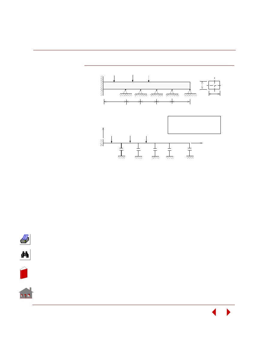
Chapter 2 Linear Static Analysis
2-112
COSMOSM Basic FEA System
Figure S75-1
L
b
h
Problem Sketch
Fa
Fb
Fc
L
1
2
L
2
L
2
L
2
FInite Element Model
16
15
14
13
12
Y
X
11
1
Load Case 1
Fa = - 1000
Fc = - 2000
Load Case 2
Fa = - 1000
Fb = - 1000
Fa
Fb
Fc
In
de
x
In
de
x

COSMOSM Basic FEA System
2-113
Part 2 Verification Problems
TYPE:
Linear static analysis, beam, plane and gap elements (BEAM2D, PLANE2D,
TRUSS2D and GAP).
PROBLEM:
The shape of the piston is simulated through gap distances. In order to avoid
singularities in the structure stiffness, two soft truss elements are used to hold the
piston. The problem is analyzed for two different pressure values.
GIVEN:
Gap Distances:
g
1
= g
7
= 0.027 in
g
2
= g
6
= 0.001 in
g
3
= g
5
= 0.008 in
g
4
= 0 in
h
= 10 in
b
= 1.2 in
k = 1 lb/in
E = 30 x 10
6
psi
Load case 1:
P = 52.5 psi
Load case 2:
P = 90.8 psi
COMPARISON OF RESULTS:
The forces in the gap elementss at a particular of time are in good agreement with
the total force applied to the piston at that time. The deformed shape of the beam for
each load case is comaptible with the forces and location of closed gaps for that load
case.\
S76: Simply Supported Beam Subject to Pressure
from a Rigid Parabolic Shaped Piston
In
de
x
In
de
x
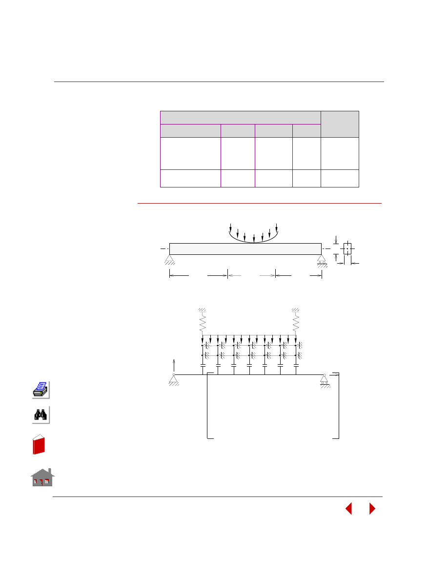
Chapter 2 Linear Static Analysis
2-114
COSMOSM Basic FEA System
Figure S76-1
Forces in Gap Elements (lb)
Total Force
(Theory)
No. of Closed Gaps
Pressure
Gap Forces
Total
4
p = 52.5
-215.5
-215.5
-1668.0
-1668.0
-3767
-3780
2
p = 90.8
-3259.0
-3259.0
-6518
-6540
120 in
120 in
60 in
p
y = (x/100) 3
h
b
Problem Sketch
p
24
25
23
22
9
1
2
3
4
5
6
7
8
g1
g7
10
11
Finite Element Model
Y
X
K
K
In
de
x
In
de
x

COSMOSM Basic FEA System
2-115
Part 2 Verification Problems
TYPE:
Static analysis, direct material property input, hexahedral solid element (SOLID).
REFERENCE:
Roark, R.J. “Formulas for Stress and Strain”, 4th Edition, McGraw-Hill Book Co.,
New York, 1965, pp. 104-106.
PROBLEM:
A beam of length L, width b, and height h is built-in at one end and loaded at the free
end with a shear force F. Determine the deflection at the free end.
GIVEN:
L
= 10 in
E
= 30E6 psi
b
= 1 in
υ =
0.3
h
= 2 in
F
= 300 lb
MODELING HINTS:
Instead of specifying the elastic material properties by E and
υ, the elastic matrix [D]
shown below is provided by direct input of its non-zero terms.
S77: Bending of a Solid Beam Using
Direct Material Matrix Input
[D]
MC11 MC12 MC13 MC14 MC15 MC16
MC22 MC23 MC24 MC25 MC26
MC33 MC34 MC35 MC36
MC44 MC45 MC46
MC55 MC56
Sym.
MC66
In
de
x
In
de
x
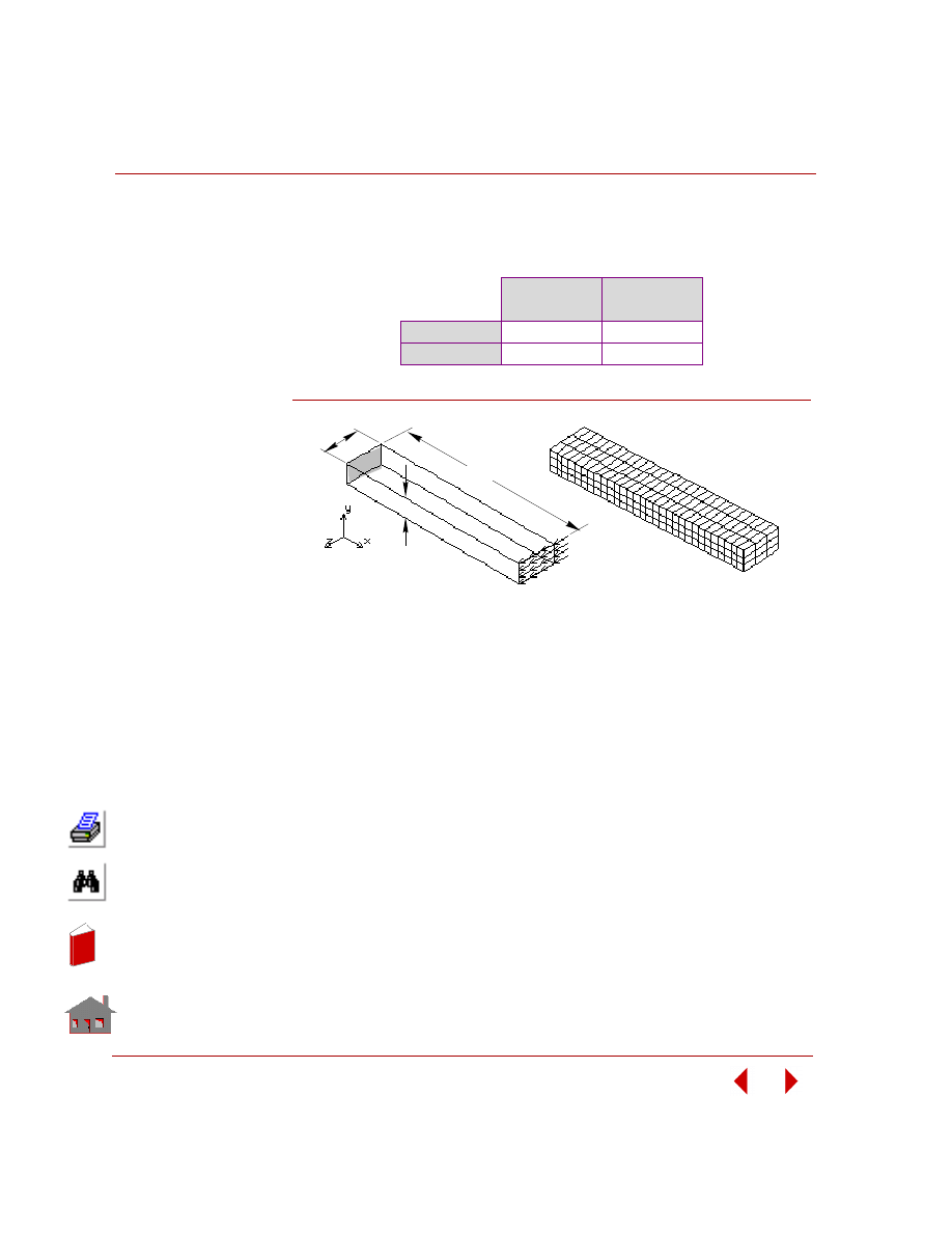
Chapter 2 Linear Static Analysis
2-116
COSMOSM Basic FEA System
RESULTS:
Displacement in Z-direction at the tip using E and
υ, is compared with those
obtained with direct input of elastic coefficients in matrix [D].
Figure S77-1
Using E and
υ
Using Direct
Matrix Input
Theory
0.005
0.005
COSMOSM
0.00496
0.00496
Finite Element
Model
Problem
Geometry
L
b
h
In
de
x
In
de
x
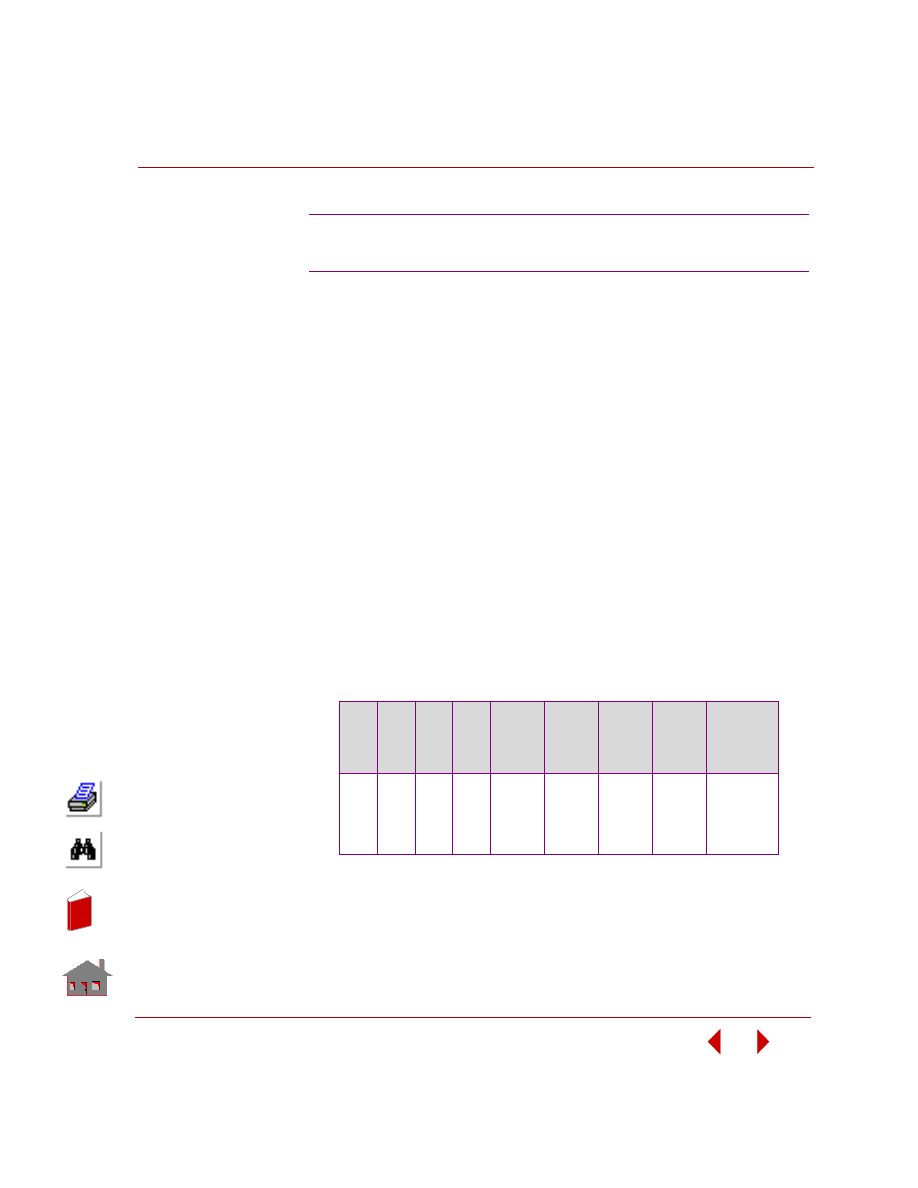
COSMOSM Basic FEA System
2-117
Part 2 Verification Problems
TYPE:
P–adaptive analysis, plane stress triangular p-element (TRIANG).
PROBLEM:
Calculate the maximum stress of a plate with a circular hole under a uniform
distributed tension load.
GIVEN:
Geometric Properties:
L
= 200 in
d
= 20 in
E
= 30 x 10
6
psi
t
= 1 in
Loading:
p
= 1 psi
RESULTS:
Nodes: 33, elements: 12, allowable local displacement error: 5%.
S78: P-Adaptive Analysis of a Square
Plate with a Circular Hole
Iter.
No.
Min
p
Max.
p
d.o.f.
Energy
x 10
-4
Max.
Displ.
x 10
-6
Max.
Stress
Local
Displ.
Error
%
No. of
Sides Not
Converged
1
2
3
4
Ref.
1
2
2
2
4
1
2
3
4
4
16
56
85
100
133
1.692
1.701
1.704
1.704
1.706
3.468
3.480
3.489
3.490
3.502
1.586
2.418
2.692
2.817
2.994
--
29.544
12.844
1.083
--
22
16
8
0
--
In
de
x
In
de
x
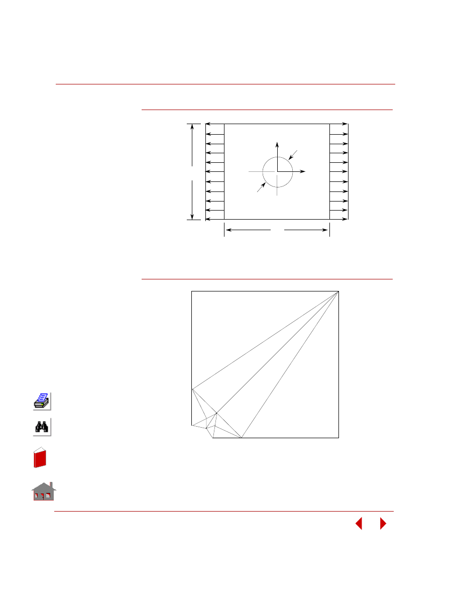
Chapter 2 Linear Static Analysis
2-118
COSMOSM Basic FEA System
Figure S78-1
Figure S78-2
L
Y
X
d
P
P
L
Plate with a Hole
2
3
4
3
4
4
4
4
4
4
3
3
3
3
3
3
2
2
2
2
2
Poly nomial O rder for Each Side at Iteration No. 4
In
de
x
In
de
x
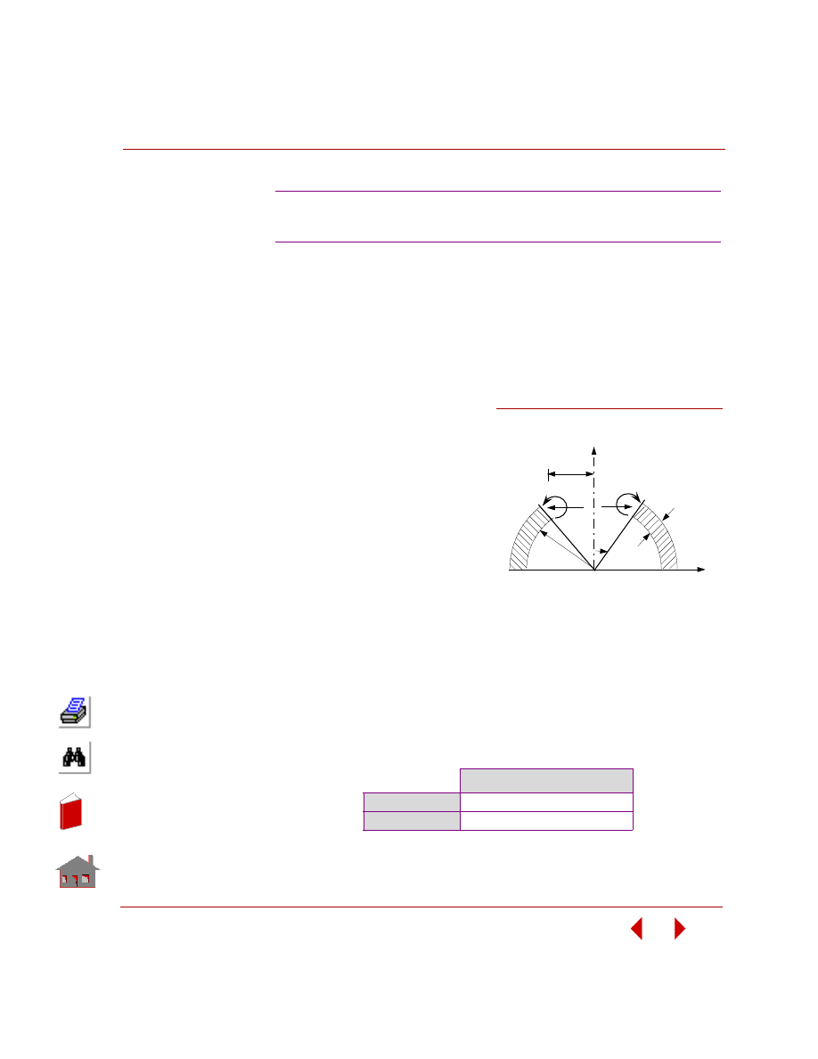
COSMOSM Basic FEA System
2-119
Part 2 Verification Problems
TYPE:
Static linear analysis using the asymmetric loading option (SHELLAX).
REFERENCE:
Zienkiewicz, O. C., “The Finite Element Method,” 3rd Edition, McGraw Hill Book
Co., p 362.
PROBLEM:
Determine the radial displacement
of a hemispherical shell under a
uniform unit moment around the
free edge.
GIVEN:
R
= 100 in
r =
50
in
t
= 2 in
E
= 1E7 psi
M = l in-lb/in
ν (NUXY) = 0.33
MODELING HINTS:
It is important to note that nodal load is to be specified per unit radian which in this
case is 50 in-lb/rad.
[M
t
= Mx Arcx = Mx Rx
Ψ = 1(50) (1) rad = 50]
Where:
Ψ = horizontal angle
COMPARISON OF RESULTS:
S79: Hemispherical Shell Under Unit
Moment Around Free Edge
Radial Displacement at Node 31
Theory
1.58E-5 in
COSMOSM
1.589E-5 in
Figure S79-1
Problem Sketch
y
R
30
H
r
H
t
x
M
M
In
de
x
In
de
x
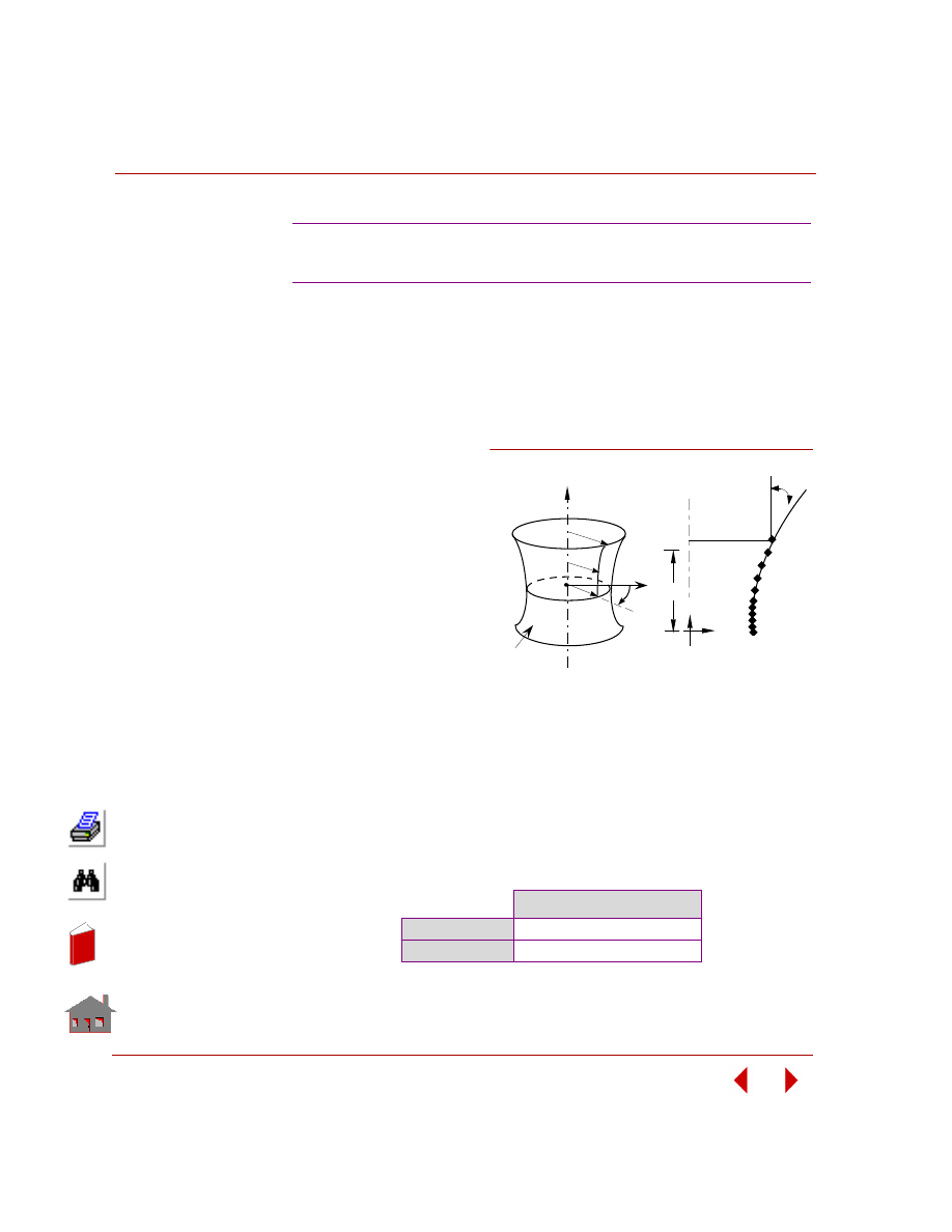
Chapter 2 Linear Static Analysis
2-120
COSMOSM Basic FEA System
TYPE:
Static linear analysis using the asymmetric loading option in SHELLAX.
REFERENCE:
NAFEMS, BranchMark Magazine, November, 1988.
PROBLEM:
Determine the stress of an
axisymmetric Hyberbolic
shell under loading F = cos2
θ
on the outward edge, y = 1.
GIVEN:
R
1
= 1 m
H
= 1 m
tan
φ = 2
(-1/2)
R
2
= 2
(1/2)
m
E =
210E3
MPa
ν (NUXY) = 0.3
Thickness = 0.01
MODELING HINTS:
Due to symmetry only half of the shell will be modeled. The Cosine load at the free
edge will be applied in terms of its x- and y- components, representing the second
term of the even function for a Fourier expansion.
COMPARISON OF RESULTS:
The results in the following table correspond to the NXZ component of stress for
element 1 as recorded in the output file.
S80: Axisymmetric Hyperbolic Shell Under a
Cosine Harmonic Loading on the Free Edge
Shear Stress (y = 0,
θ
= 45
°
)
Theory
-81.65 MPa
COSMOSM
-79.63 MPa
φ
A
11
Y
H
r
B
A
θ
Y = r -1
3
R
r
2
Y
Problem Sketch
x
B
1
R
Finite Element Model
1
Figure S80-1
In
de
x
In
de
x
COSMOSM Basic FEA System
2-121
Part 2 Verification Problems
TYPE:
Static linear analysis using the asymmetric loading option in SHELLAX.
REFERENCE:
SHELL4 elements are used for comparison purposes.
PROBLEM:
A circular plate with inner and outer radii of 3 in and 10 in respectively, is subjected
to a non-axisymmetric load around outer circumference from
θ = -54° to θ = 54°
perpendicular to the plate surface. The load distribution is:
F (
θ) = 5.31 [1 + cos(10
θ
/3)]*10
3
GIVEN:
R
i
= 3 in
R
0
= 10 in
E
= 3E7 psi
t
= 1 in
ν (NUXY) = 0.3
MODELING HINTS:
A total of seven elements are considered in this example. Note that since the load is
symmetric about the x-axis, it will be considered only between
θ
= 0
° and
θ
= 54°
at 3
° intervals, and represented by the even (Cosine) terms of the Fourier expansion.
Only the first six (Cosine) terms will be included.
COMPARISON OF RESULTS:
S81: Circular Plate Under
Non-Axisymmetric Load
Displacement of Outer Edges
(
θ
= 180
°
) in the Axial Direction
SHELLAX
5.80 x 10
-4
in
SHELL4
5.62 x 10
-4
in
In
de
x
In
de
x
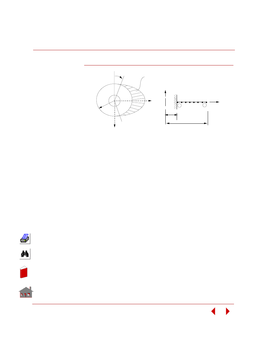
Chapter 2 Linear Static Analysis
2-122
COSMOSM Basic FEA System
Figure S81-1
Problem Sketch
z
R
0
= -54
°
X
= +54
°
Finite Element Model
R
R
0
i
1
Y
1 2 3
X
4 5 6
7
8
7
θ
θ
Load
Distribution
In
de
x
In
de
x
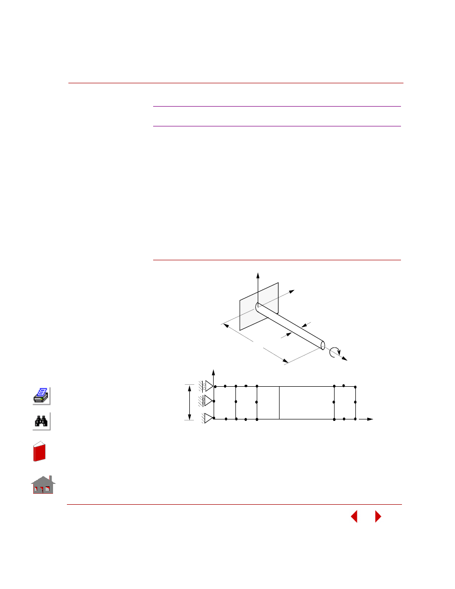
COSMOSM Basic FEA System
2-123
Part 2 Verification Problems
TYPE:
Static analysis, PLANE2D element using asymmetric loading option.
REFERENCE:
Timoshenko, S., “Strength of Materials,” 3rd Edition, D. Van Nostrand Co., Inc.,
New York, 1956.
PROBLEM:
A long solid circular shaft is built-in at one end and subjected to a twisting moment
at the other end. Determine the maximum shear stress,
τ
max, at the wall due to the
moment.
Figure S82-1
S82: Twisting of a Long Solid Shaft
d/2
_ 0 0
0 0
3
5
8
2
7
12
1
4
6
9
11
63
62
61
X
Y
56
57
58
Finite Element Model
60
59
x
Z
d
L
M
y
Problem Sketch
In
de
x
In
de
x
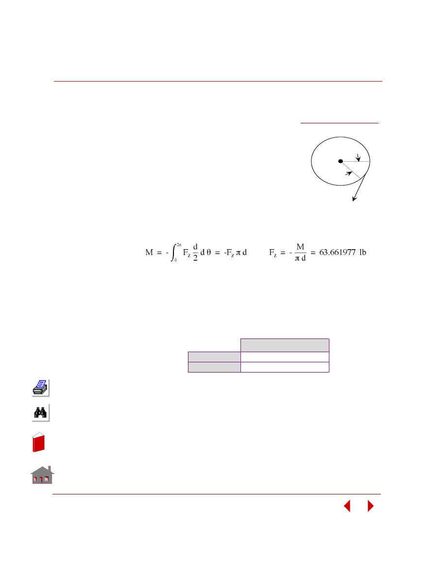
Chapter 2 Linear Static Analysis
2-124
COSMOSM Basic FEA System
GIVEN:
E
= 30E6 psi
L
= 24 in
d
= 1 in
M = -200 in-lb
MODELING HINTS:
Since the geometry is axisymmetric about the y-axis,
the finite element model, shown in the figure above, is
considered for analysis. The effect of the applied
moment is calculated in terms of a tangential force
integrated around the circumference of the circular rod.
ANALYTICAL SOLUTION:
The load is applied at (node 63) in the z-direction (circumferential). Ux (radial)
constraints are not imposed at the wall in order to allow freedom of cross-sectional
deformation which corresponds to the assumptions of “negligible shear” stated in
the reference.
COMPARISON OF RESULTS:
At clamped edge (node 3).
Max Shear Stress (psi)
τ
13
Theory
1018.4
COSMOSM
1018.4
d
θ
Fz
Figure S82-2
In
de
x
In
de
x
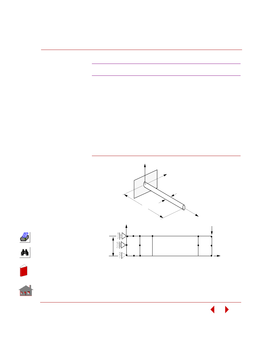
COSMOSM Basic FEA System
2-125
Part 2 Verification Problems
TYPE:
Static analysis, PLANE2D element using the asymmetric loading option.
REFERENCE:
Timoshenko, S., “Strength of Materials,” 3rd Edition, D. Van Nostrand Co., Inc.,
New York, 1956.
PROBLEM:
A long solid circular shaft is built-in at one end and at the other end a vertical force
is applied. Determine the maximum axial stress
σ
y at the wall and at one inch from
the wall due to the force.
Figure S83-1
S83: Bending of a Long Solid Shaft
_ 0 0
0 0
3
5
8
2
7
1
4
6
63
50
61
X
Fx
Y
58
56
Finite Element Model
d/2
x
Z
d
L
y
Problem Sketch
In
de
x
In
de
x
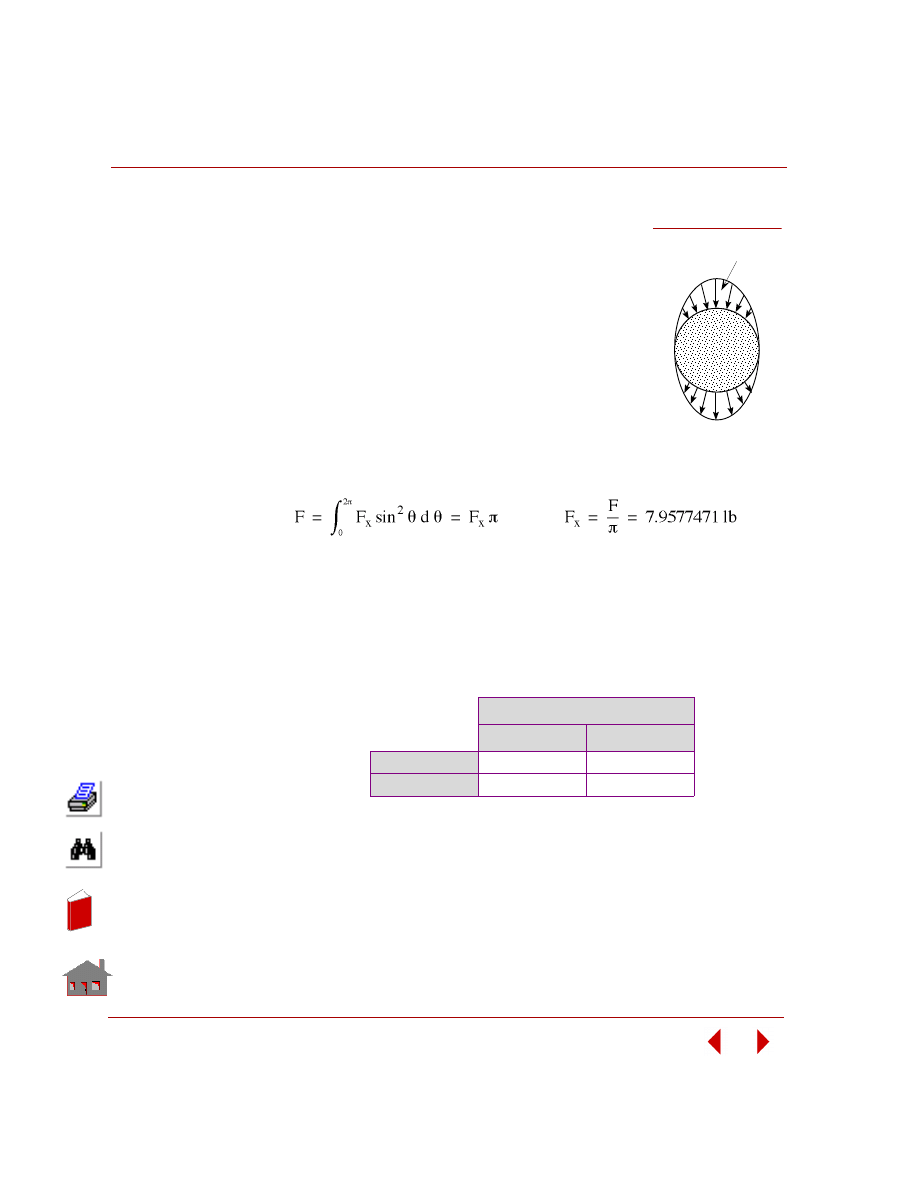
Chapter 2 Linear Static Analysis
2-126
COSMOSM Basic FEA System
GIVEN:
E
= 30E6 psi
L
= 24 in
d
= 1 in
F
= -25 lb
MODELING HINTS:
The finite element model is formed as noted in the figure
considering the axisymmetric nature of the problem. The
force applied at node 63 is calculated based on a Fourier
Sine expansion representing its antisymmetric nature.
ANALYTICAL SOLUTION:
The load is applied at (node 75) in the z-direction (circumferential). Ux (radial)
constraints are not imposed at the wall in order to allow freedom of cross-sectional
deformation which corresponds to the assumptions of “negligible shear” stated in
the reference.
COMPARISON OF RESULTS:
At element 1 and
θ = 90°.
Max Axial Stress (sy psi)
y = 0 (Node 3)
y = 1 in (Node 5)
Theory
6111.6
5856.9
COSMOSM
6115.1
5856.8
Load Distribution
Fr
Figure S83-2
In
de
x
In
de
x
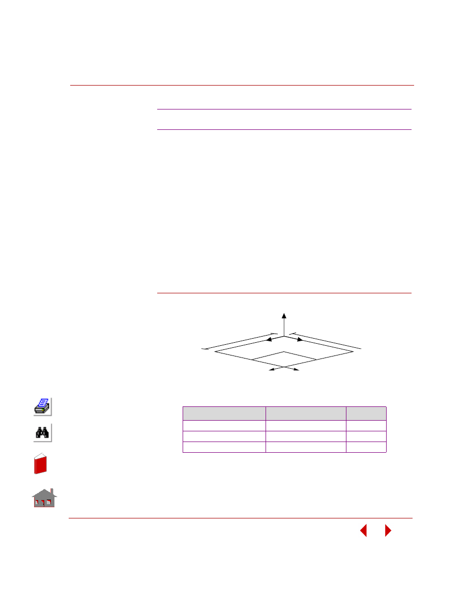
COSMOSM Basic FEA System
2-127
Part 2 Verification Problems
TYPE:
Static analysis TRIANG element using the submodeling option.
PROBLEM:
Calculate the maximum von Mises stress for a square plate under a concentrated
load at one corner. Compare the displacement and stress results from a fine mesh to
the results from an originally coarse mesh improved using submodeling.
GIVEN:
a
= 25 in
E
= 30 E6 psi
b
= 25 in
t
= 0.1 in
Fx = Fy = 1000 lbs
Figure S84-1
COMPARISON OF RESULTS:
S84: Submodeling of a Plate
Mesh Type
Max Deflection at Node 1
Max Stress
Coarse Mesh
-0.00131
3810
Coarse Mesh + Submodeling
-0.00156
7626
Fine Mesh and Theory
-0.00156
7620
Z
X
Y
a
b
submodel
FX=1000
FY=1000
FIXED
EDGE
FIXED
EDGE
FREE ED
GE
FREE ED
GE
In
de
x
In
de
x
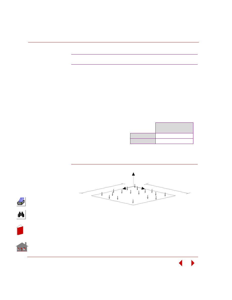
Chapter 2 Linear Static Analysis
2-128
COSMOSM Basic FEA System
TYPE:
Static analysis, SHELL4 plate elements on elastic foundation.
PROBLEM:
A simply supported plate is subjected to uniform pressure P. The full plate is
supported by elastic foundation. For small flexural rigidity, the calculated pressure
applied to the plate from the foundation approaches the applied external pressures.
The flexural rigidity decreases by decreasing the thickness and modulus of elasticity.
Figure S85-1
NOTE:
Foundation pressure is recorded in the output file for each element in the last column
of element stress results.
S85: Plate on Elastic Foundation
GIVEN:
E
= 30 x 10 psi
ν
= 0.3
h
= 0.01 in
a
= 10 in
b
= 10 in
P
= 10 psi
COMPARISON OF RESULTS:
Foundation Pressure
at Element 200
Theory
-10.0
COSMOSM
-10.0
Z
X
Y
a
b
Pressure P
SIMP
LY SU
PPOR
TED
SIMPLY SU
PPOR
TED
In
de
x
In
de
x
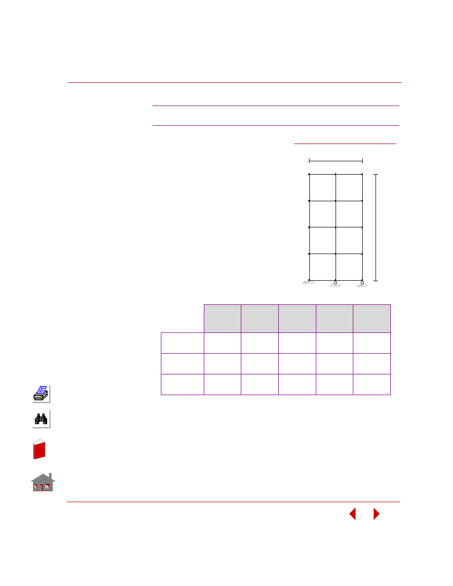
COSMOSM Basic FEA System
2-129
Part 2 Verification Problems
TYPE:
Static analysis, PLANE2D element,
coupled degrees of freedom.
PROBLEM:
Determine displacements for the plate
shown in the figure below such that
translations in the Y-direction are
coupled for nodes 5, 10, and 15.
GIVEN:
EX = 3.0E10, 3.0E09, and 3.0E8 psi
ν
= 0.25
COMPARISON OF RESULTS:
Displacements for the coupled D.O.F.
ANALYTICAL SOLUTION:
U10 = U5 = FL/AE
S86: Plate with Coupled Degrees of Freedom
Young’s
Modulus
U5 (Y-
Translation
at Node 5)
U10 (Y-
Translation
at Node 10)
U15 (Y-
Translation
at Node 15)
U10/U5
Theory
COSMOSM
3.0E10
5.33333E-7
5.33333E-7
5.33333E-7
5.33333E-7
5.33333E-7
5.33333E-7
1.000
1.000
Theory
COSMOSM
3.0E09
5.33333E-6
5.33333E-6
5.33333E-6
5.33333E-6
5.33333E-6
5.33333E-6
1.000
1.000
Theory
COSMOSM
3.0E08
5.33333E-5
5.33333E-5
5.33333E-5
5.33333E-5
5.33333E-5
5.33333E-5
1.000
1.000
Figure S86-1
1
20 in
10 in
2
3
4
5
6
7
8
9
10
11
12
13
14
15
In
de
x
In
de
x
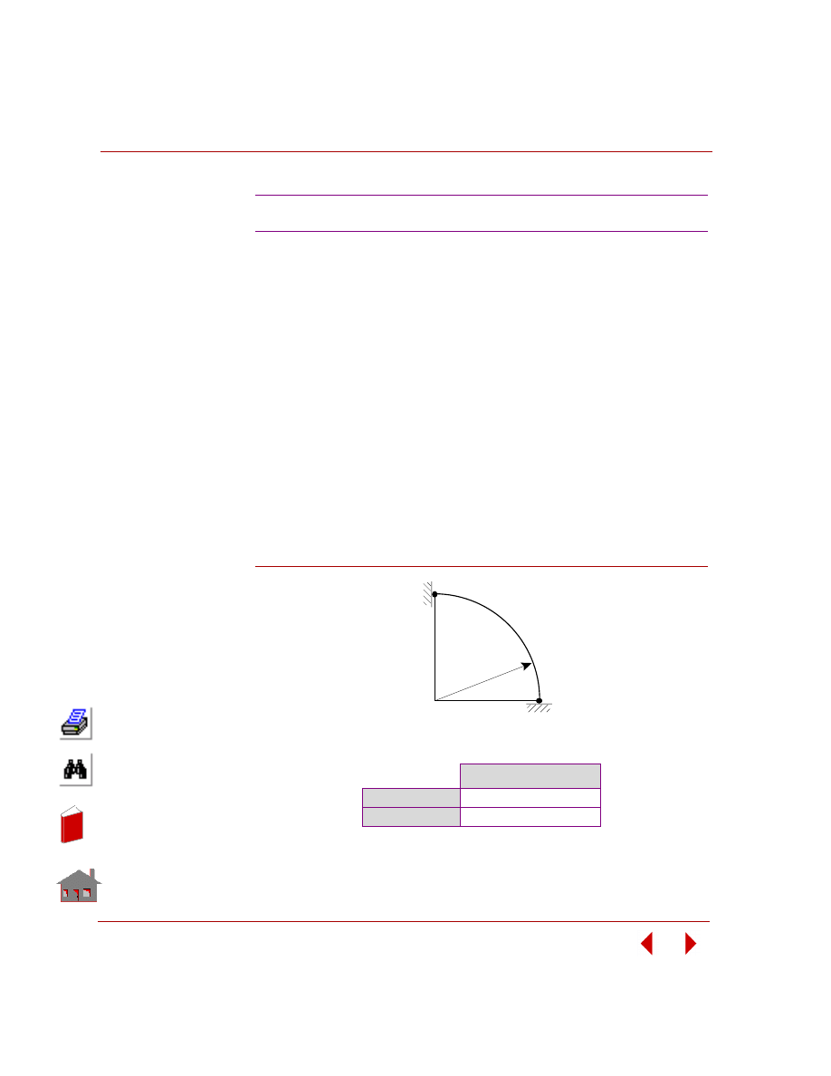
Chapter 2 Linear Static Analysis
2-130
COSMOSM Basic FEA System
TYPE:
Linear static analysis, ELBOW element with pipe cross-section subjected to gravity
loading.
PROBLEM:
Case A:
Reduced gravity loading (fixed-end moments ignored)
Case B:
Consistent gravity loading (fixed-end moments considered)
GIVEN:
g
= -32.2 in/sec
2
EX = 3.0E7 psi
ρ
= 7.82
Elbow wall thickness
= 0.1 in
Elbow outer diameter
= 1.0 in
Elbow radius of curvature
= 10.0 in
Figure S87-1
COMPARISON OF RESULTS:
S87: Gravity Loading of ELBOW Element
Y-Translation at Node 51
Case A
-7.42E-3
Case B
-6.41E-3
Node 51
Node 1
In
de
x
In
de
x
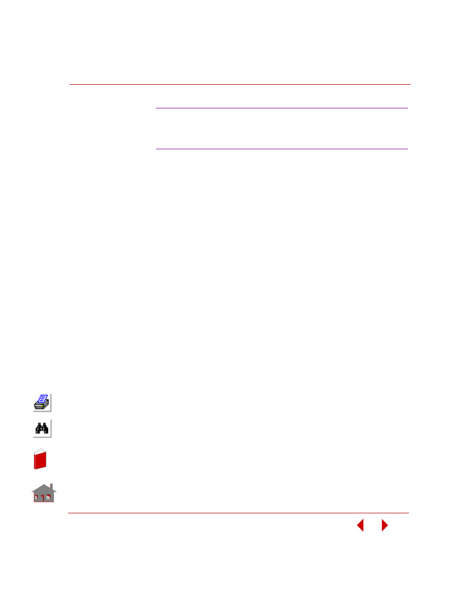
COSMOSM Basic FEA System
2-131
Part 2 Verification Problems
TYPE:
Static analysis, J-integral, stress intensity factor, plane stress conditions.
S88A:
Using 6-node triangular plane element (TRIANG)
S88B:
Using 8-node rectangular plane element (PLANE2D)
REFERENCE:
Brown, W. F., Jr., and Srawley, J. E., “Plane Strain Crack Toughness Testing of High
Strength Metallic Materials,” ASTM Special Technical Publication 410,
Philadelphia, PA, 1966.
PROBLEM:
Determine the stress intensity factor for a single-edge-cracked bend specimen using
the J-integral.
GIVEN:
E
= 30 x 10
6
psi
υ = 0.3
Thickness = 1 in
a
= 2 in
b
= 4 in
L
= 32 in
P = 1 lb
MODELING HINTS:
Three circular J-integral paths centered at the crack tip are considered. Due to
symmetry, only one half of the model is modeled.
S88A, S88B: Single-Edge Cracked Bend
Specimen, Evaluation of Stress Intensity
Factor Using the J-integral
In
de
x
In
de
x
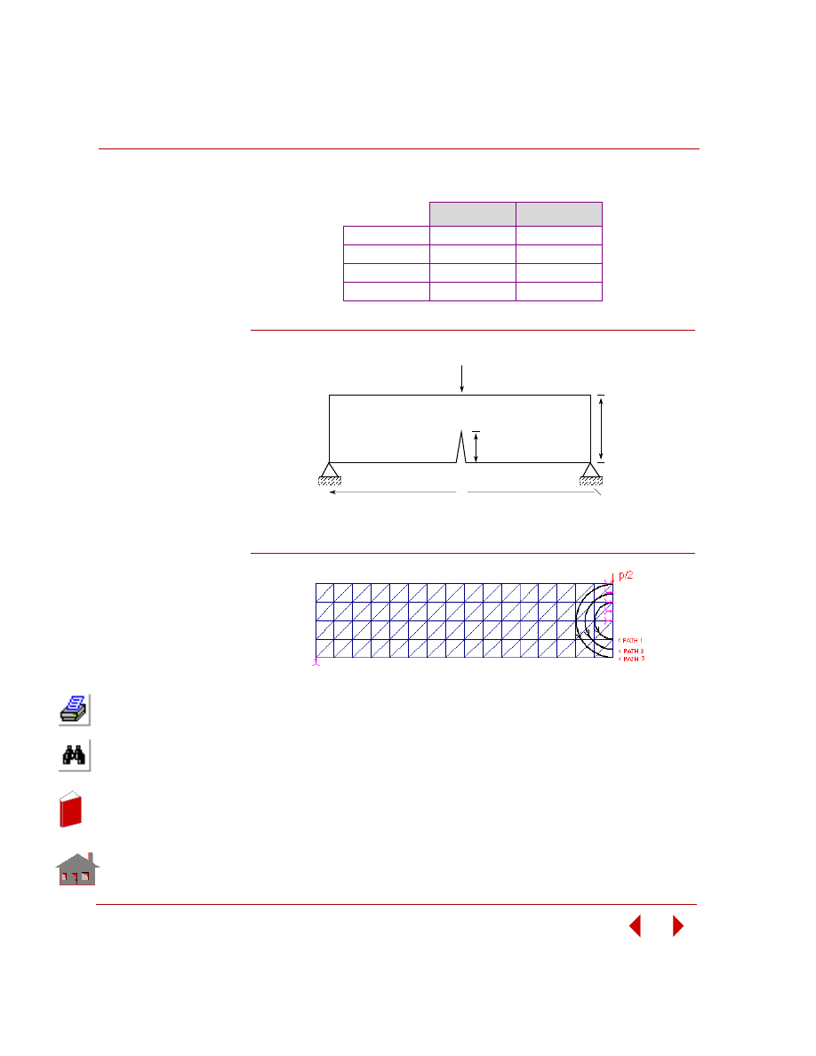
Chapter 2 Linear Static Analysis
2-132
COSMOSM Basic FEA System
COMPARISON OF RESULTS
Figure S88-1
Figure S88-2
K
I
(TRIANG)
K
I
(PLANE2D)
Theory
10.663
10.663
Path 1
9.9544
9.1692
Path 2
10.145
10.974
Path 3
10.240
10.648
b
a
P
L
Full Model
In
de
x
In
de
x

COSMOSM Basic FEA System
2-133
Part 2 Verification Problems
TYPE:
Static analysis, J-integral, stress intensity factors (combined mode crack), plane
strain conditions.
S89A:
Using 6-node triangular plane element (TRIANG)
S89B:
Using 3-node triangular plane element (TRIANG)
S89C:
Using 8-node rectangular plane element (PLANE2D)
S89D:
Using 4-node rectangular plane element (PLANE2D)
REFERENCE:
Bowie, O. L., “Solutions of Plane Crack Problems by Mapping Techniques,” in
Mechanics of Fracture I, Methods of Analysis and Solutions of Crack Problems (Ed
G.C. Shi), pp. 1-55, Noordhoff, Leyden, Netherlands, 1973.
PROBLEM:
Determine the stress intensity factor for both modes of fracture (opening and
shearing) for a rectangular plate with an inclined edge crack subjected to uniform
uniaxial tensile pressure at the two ends.
GIVEN:
σ = 1 psi
h
= 2.5 in
W = 2.5 in
a
= 1 in
E
= 30 x 10
6
psi
υ
= 0.3
Thickness =1 in
φ =
45
°
MODELING HINTS:
The full part has to be modeled since the model is not symmetric with respect to the
crack. There is no restriction in the type of the mesh to be used and the mesh could
S89A, S89B: Slant-Edge Cracked Plate, Evaluation
of Stress Intensity Factors Using the J-integral
In
de
x
In
de
x
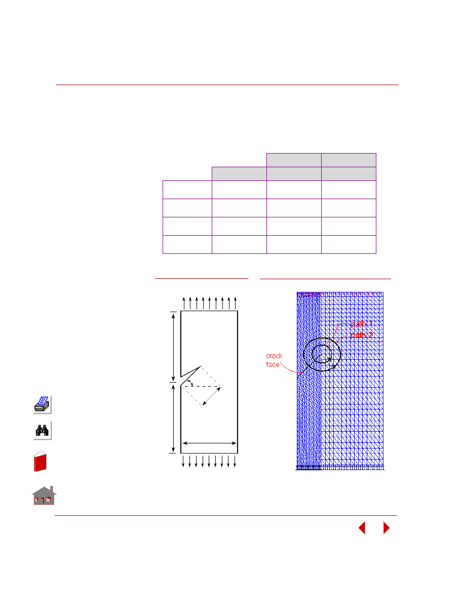
Chapter 2 Linear Static Analysis
2-134
COSMOSM Basic FEA System
be either symmetric or non-symmetric with respect to the crack. However, the nodes
in the two sides of crack should not be merged in order to model the rupture area
properly.
COMPARISON OF RESULTS:
K
I
K
II
Reference
1.85
0.880
6-node element
(S89A.GEO)
Path 1
Path 2
1.82
1.82
0.876
0.877
3-node element
(S89B.GEO)
Path 1
Path 2
1.76
1.77
0.835
0.873
8-node element
(S89C.GEO)
Path 1
Path 2
1.80
1.79
0.872
0.874
4-node element
(S89D.GEO)
Path 1
Path 2
1.73
1.71
0.879
0.845
h
h
w
a
φ
σ
σ
Figure S89-1
Figure S89-2
2
In
de
x
In
de
x

COSMOSM Basic FEA System
2-135
Part 2 Verification Problems
TYPE:
Static analysis, J-integral, stress intensity factor, axisymmetric geometry.
S90A:
Using 8-node rectangular plane element (PLANE2D)
S90B:
Using 6-node triangular plane element (TRIANG)
REFERENCE:
Tada, H. and Irwin, R., “the stress analysis of cracks Handbook,” Paris Productions,
Inc., pp. 27.1, St. Louis, MI, 1985.
PROBLEM:
Determine the stress intensity factor for a circular crack inside a round bar subjected
to uniform axial tensile pressure at the two ends.
GIVEN:
σ = 1 psi
H = 25 in
R = 5 in
a = 2.5 in
E = 30 x 10
6
psi
γ = 0.28
MODELING HINTS:
Since the model is symmetric with respect to the crack, therefore only one-half of
the model (lower half here) is needed for the analysis.
S90A, S90B: Penny-Shaped Crack in Round
Bar, Evaluation of Stress Intensity Factor
Using the J-integral
In
de
x
In
de
x
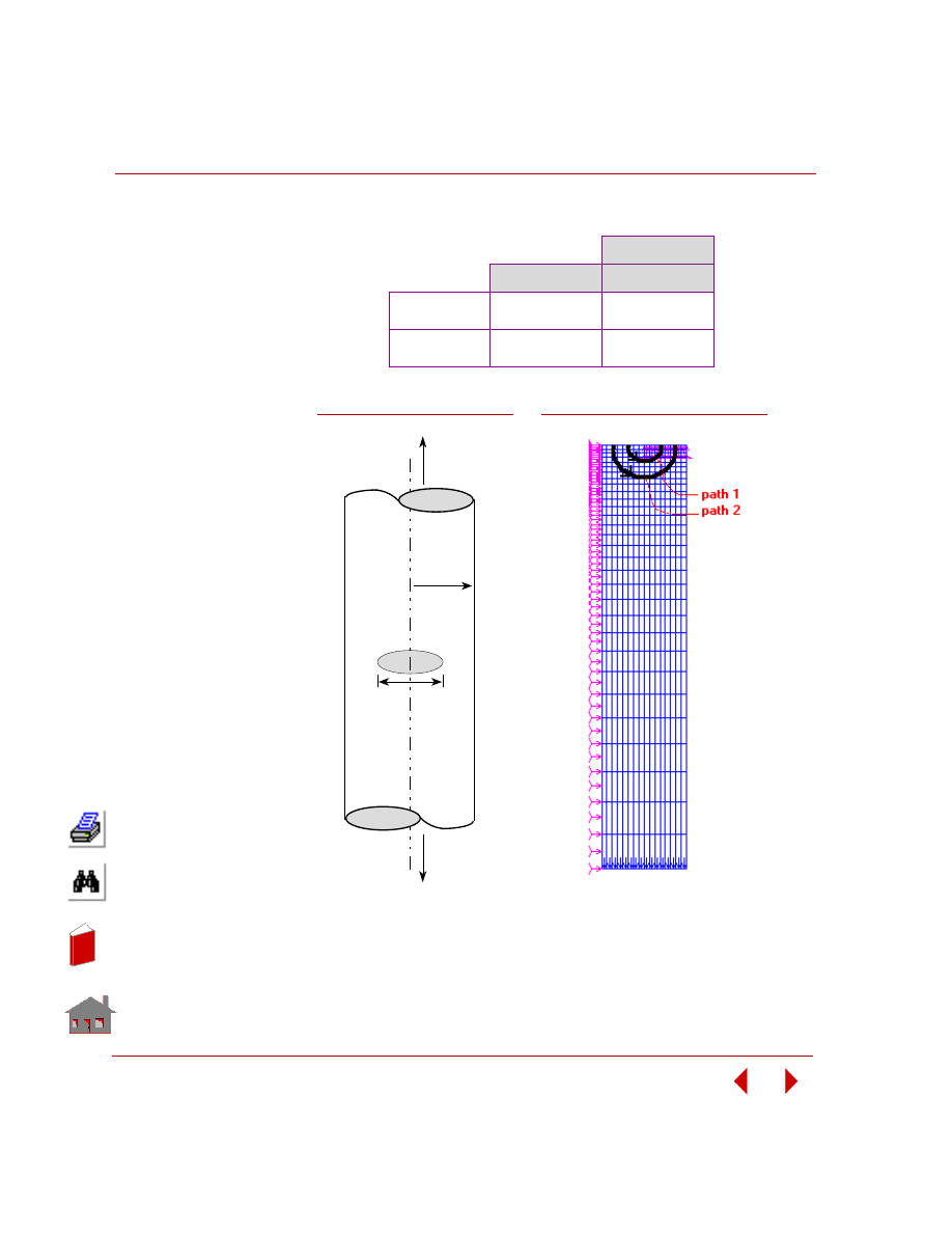
Chapter 2 Linear Static Analysis
2-136
COSMOSM Basic FEA System
COMPARISON OF RESULTS:
K
I
Reference
1.94
8-node element
(S90A.GEO)
Path 1
Path 2
1.90
1.91
6-node element
(S90B.GEO)
Path 1
Path 2
1.89
1.90
σ
σ
2a
R
Figure S90-1
Figure S90-2
2
In
de
x
In
de
x
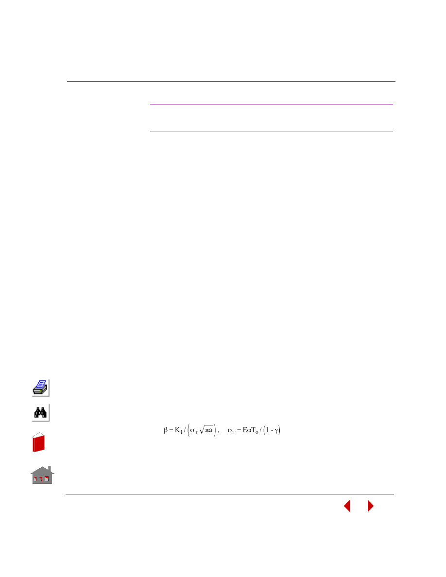
COSMOSM Basic FEA System
2-137
Part 2 Verification Problems
TYPE:
Static analysis, thermal loading, J-integral, stress intensity factor, plane strain
conditions.
REFERENCE:
Wilson, W. K. and Yu, I. W., “The Use of the J-integral in Thermal Stress Crack
Problems,” International Journal of Fracture, Vol. 15, No. 4, August 1979.
PROBLEM:
Determine the stress intensity factor for an edge crack strip subjected to thermal
loading. The strip is subjected to a linearly varying temperature through its thickness
with zero temperature at midthickness and temperature T
o
at the right edge (x=w/2).
The ends are constrained.
GIVEN:
L
= 20 in
w = 10 in
a
= 5 in
E
= 30 x 10
6
psi
γ
= 0.28
α = 7.4 x 10
-6
in/in-
°F
T
o
= 10
°F
MODELING HINTS:
Due to symmetry, only one-half of the geometry is modeled (lower half in this
problem).
COMPARISON OF RESULTS:
where:
β = K
1
/12220.27
S91: Crack Under Thermal Stresses, Evaluation
of Stress Intensity Using the J-integral
In
de
x
In
de
x
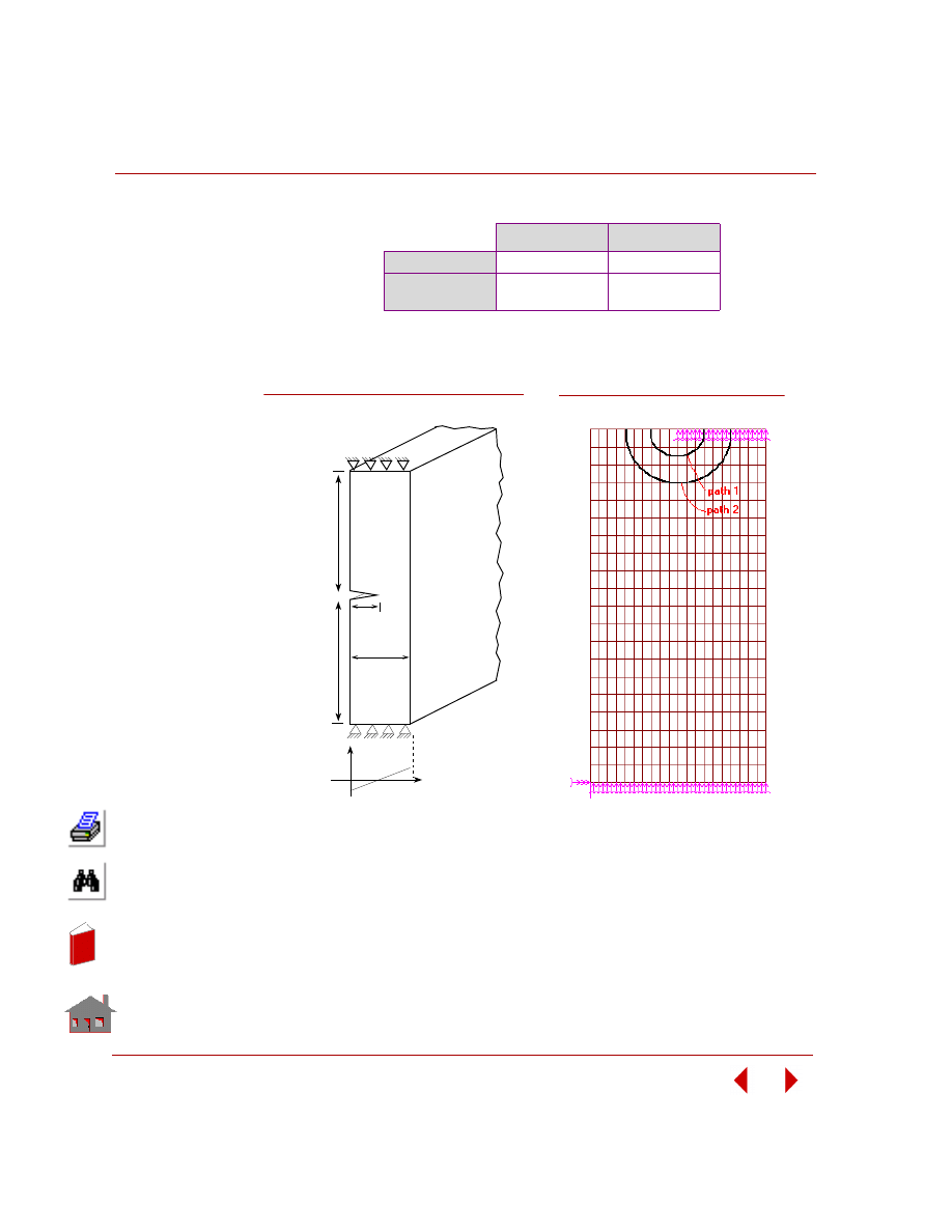
Chapter 2 Linear Static Analysis
2-138
COSMOSM Basic FEA System
K
I
K
I
/
β
Reference
0.5036
*
Path 1
Path 2
6141.4
6176.3
0.5034
0.5054
*
Average value of the five paths in the reference
Figure S91-2
2
Thickness
Temperature
To
-To
L
L
w
a
Figure S91-1
In
de
x
In
de
x
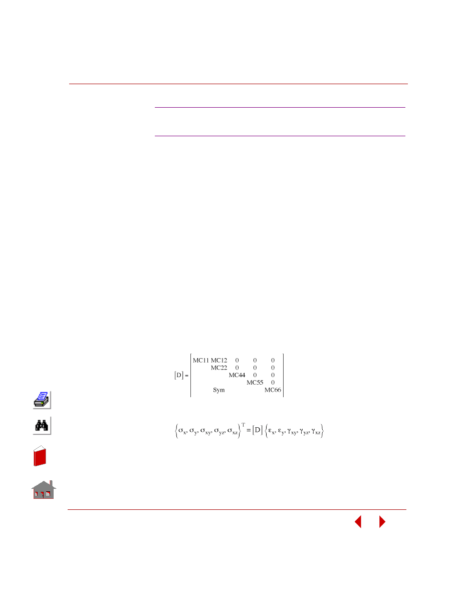
COSMOSM Basic FEA System
2-139
Part 2 Verification Problems
TYPE:
Static analysis, direct material input, SHELL3L element.
REFERENCE:
Timoshenko, S. P. and Woinowsky-Krieger, “Theory of Plates and Shells,”
McGraw-Hill Book Co., 2nd edition, pp. 143-120, 1962.
PROBLEM:
Calculate the deflection and stresses at the center of a simply supported plate
subjected to a concentrated load F.
GIVEN:
MODELING HINTS:
Instead of specifying the elastic properties by E and
ν, the elastic matrix [D] shown
below (in the default element coordinate system) is provided by direct input of its
non-zero terms.
where, [D] relates the element strains to the element stresses according to Hook's
law:
Note that the [D] matrix is reduced to a 5x5 matrix from the general form of 6x6
matrix, by considering the fact that
σ
z
= 0 for shell element, thus eliminating the
third row and column of the general [D] matrix.
S92A, S92B: Simply Supported Rectangular
Plate, Using Direct Material Matrix Input
E
= 30 x 10
6
psi
G
xy
= G
yz
= G
xz
= 11.538 x 10
6
psi
ν
= 0.3
h
= 1 in
a
= b = 40 in
F
= 400 lbs
In
de
x
In
de
x
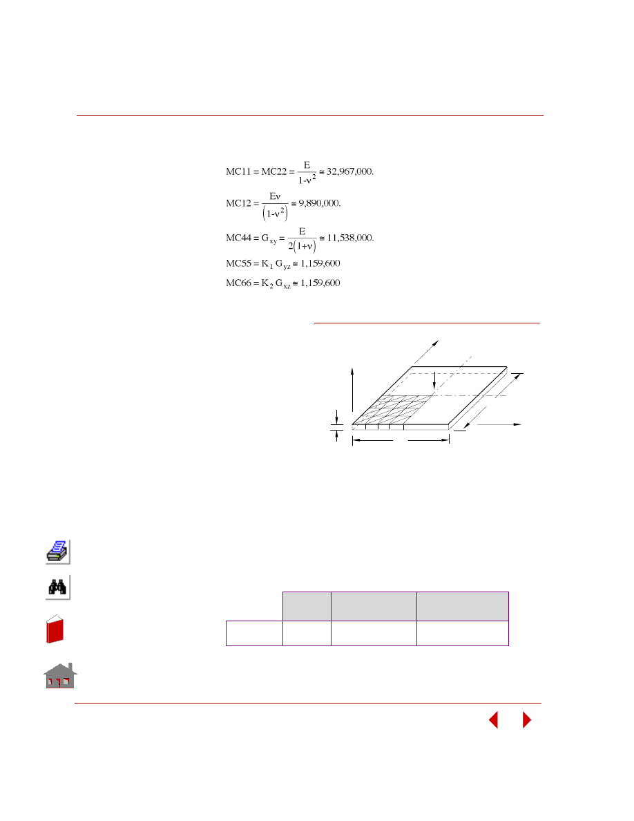
Chapter 2 Linear Static Analysis
2-140
COSMOSM Basic FEA System
Considering an isotropic property, the terms of [D] matrix are:
The terms K
1
and K
2
are
shear correction factors
which are chosen to match
the plate theory with certain
classical solutions and are
functions of thickness and
material properties. When
you input regular material
properties (E,
ν), the shear
factors are evaluated
internally in the program as
K
1
= K
2
= 0.1005 (as in
S92B). For the sake of
consistency, the same values
are used for the evaluation of
MC55 and MC66 in S92A.
Due to symmetry in geometry and load, only a quarter of the plate is modeled.
COMPARISON OF RESULTS:
Maximum displacement (in Z-direction) at the tip of the plate (Node 25) using E and
ν (S92B) is compared with the result obtained from direct input of the elastic
coefficients in matrix [D] (S92A).
Theory
Using Direct Matrix
Input (S92A)
Using E and
ν
(S92B)
Maximum UZ
(in)
-0.0270
-0.02746
-0.02746
Z
Y
X
h
1
b
a
5
21
25
F
Figure S92-1
Problem Sketch and Finite Element Model
In
de
x
In
de
x
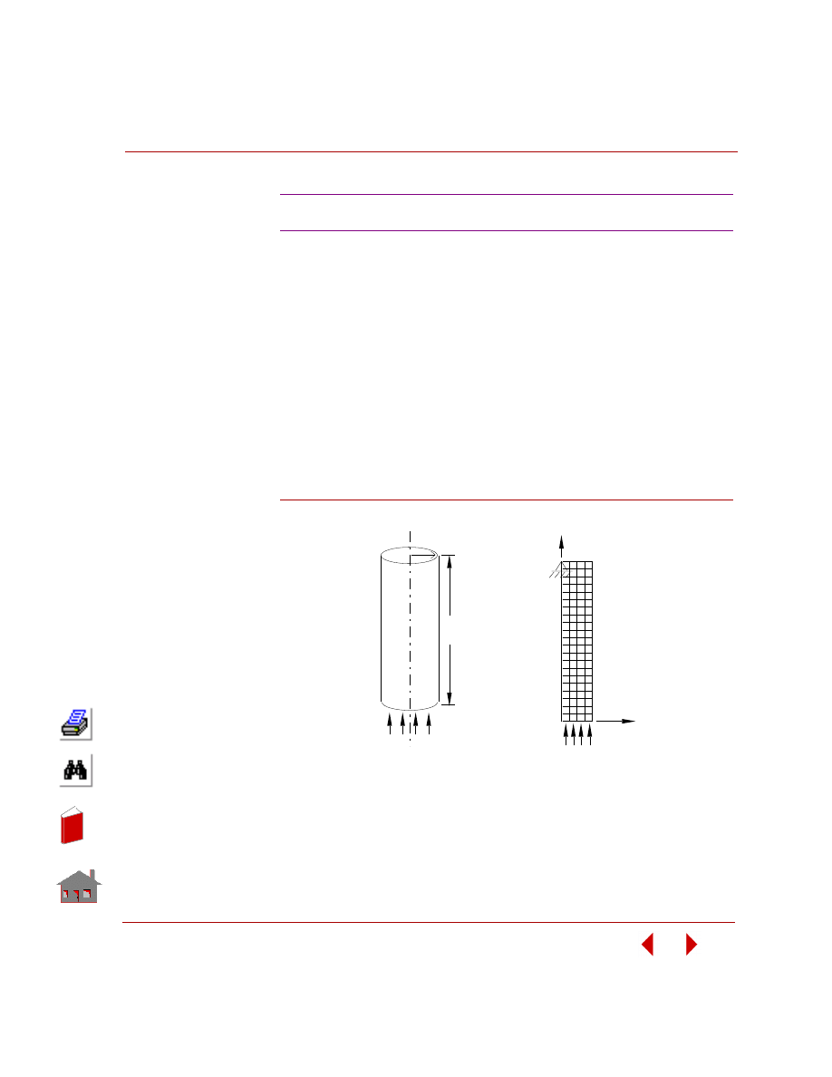
COSMOSM Basic FEA System
2-141
Part 2 Verification Problems
TYPE:
Static analysis, inertia relief, PLANE2D element, (axisymmetric option).
PROBLEM:
A cylinder is accelerating under unbalanced external loads. Find the induced
counter-balance acceleration and the amount by which the cylinder will be
shortened.
GIVEN:
EX = 3.E7 psi
γ
= 0.28 lb sec
2
/in
4
ρ
= 7.3E-4
Figure S93-1
S93: Accelerating Rocket
Actual Model
H = 100 in
P = 100 psi
X
Y
Finite Element Model
R = 10 in
In
de
x
In
de
x
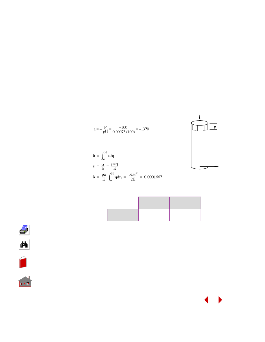
2-142
COSMOSM Basic FEA System
MODELING HINTS:
To avoid instability in FEA solution, one node should be constrained in Y-direction.
A node on the top end of the cylinder is selected for that purpose rather than on the
bottom end. Constraining any node on the surface where the pressure is applied
eliminates the components of the load of that node and hence causes inaccuracy in
the solution.
ANALYTICAL SOLUTION:
a) The induced counter-balance acceleration:
F + Ma = 0
P
π R
2
= -
ρ π R
2
Ha
b) Length shortening
COMPARISON OF RESULTS:
* See output file.
Acceleration
(a)
Displacement u
y
at Node 5
Theory
-1370
0.0001667
COSMOSM
-1370
*
0.0001669
Figure S93-2
X
Y
η
In
de
x
In
de
x
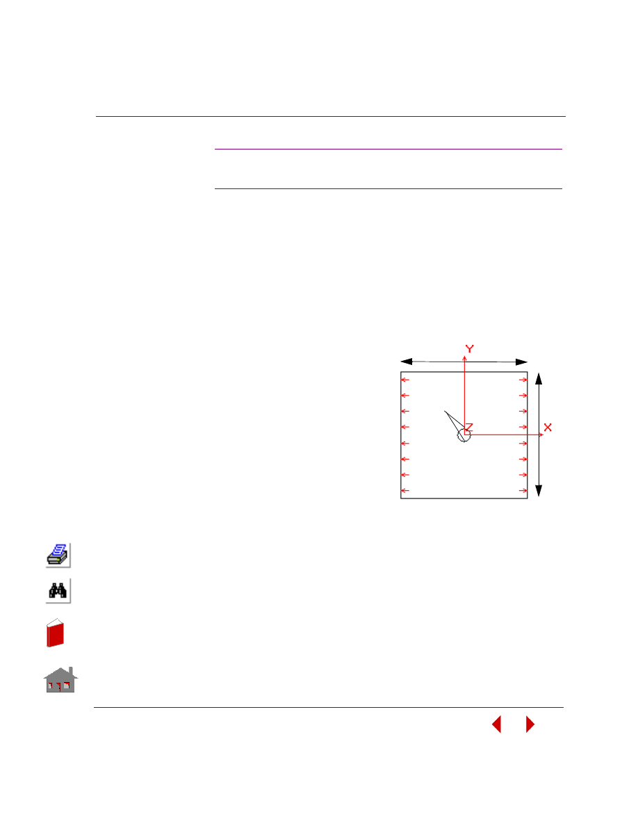
COSMOSM Basic FEA System
2-143
Part 2 Verification Problems
TYPE:
Static analysis using the p-method. S94A: plane stress triangular elements
(TRIANG). S94B: plane stress quadrilateral elements ( PLANE2D). S94C:
Tetrahedral elements (TETRA10).
PROBLEM:
Calculate the maximum stress of a plate with a circular hole under a uniformly
distributed tension load. Use strain energy to adapt the p-order.
GIVEN:
Geometric Properties:
L = side of the plate = 10.00 in
d = diameter of the hole = 1.00 in
t = thickness of the plate = 0.25 in
Material Properties:
E = 3.0E7 psi
ν = 0.3
Loading:
P = 100 psi
-
A coarse mesh is intentionally used to demonstrate the power of the p-method
S94A, S94B, S94C: P-Method Solution of a Square
Plate with a Small Hole
10”
10”
1” diameter
P
r
e
s
s
u
r
e
stress
concentration
Figure S94-1: The Plate with a Hole Model
In
de
x
In
de
x
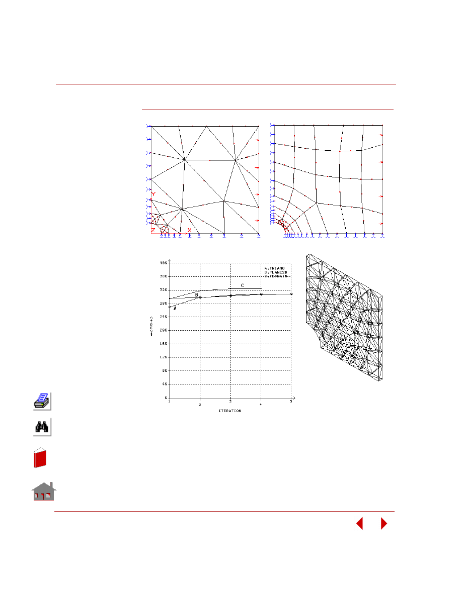
Chapter 2 Linear Static Analysis
2-144
COSMOSM Basic FEA System
Figure S94-2 Meshed Quarter of the Plate.
S94C: TETRA10 Elements
S94A: TRIANG Elements
S94B: PLANE2D elements
Convergence Plots Using Different Element Types
In
de
x
In
de
x
COSMOSM Basic FEA System
2-145
Part 2 Verification Problems
COMPARISON OF RESULTS:
Reference:
Walter D. Pilkey, “Formulas For Stress, Strain, and Structural Matrices,” Wiley-
Interscience Publication, John Wiley & Sons, Inc., 1994, pp. 271.
Theory
COSMOSM
Relative Error
Max. Stress in X-
Direction
(TRIANG)
300 psi
308 psi (p-order = 4)
2.7%
Max. Stress in X-
Direction
(PLANE2D)
300 psi
308 psi (p-order = 3)
2.7%
Max. Stress in X-
Direction
(TETRA10)
300 psi
323 psi (p-order = 5)
7.7%
In
de
x
In
de
x
Chapter 2 Linear Static Analysis
2-146
COSMOSM Basic FEA System
TYPE:
Static analysis, axisymmetric triangular (6-node TRIANG) and quadrilateral (8-
node PLANE2D) p-elements with the polynomial order of shape function equal to 8.
PROBLEM:
Calculate the maximum stress of a circular shaft with a U-shape circumferential
groove under a uniformly distributed tension load. P-order is adapted by checking
strain energy of the system.
GIVEN:
Geometric Properties:
L = 0.9 in
D = 2 in
d = 0.2 in
Material Properties:
E = 3.0E7 psi
ν = 0.3
Loading:
P = 100 psi
S95A, S95B, S95C: P-Method Solution of a U-
Shaped Circumferential Groove in a Circular Shaft
Figure S95-1: The Circular Shaft Model
In
de
x
In
de
x
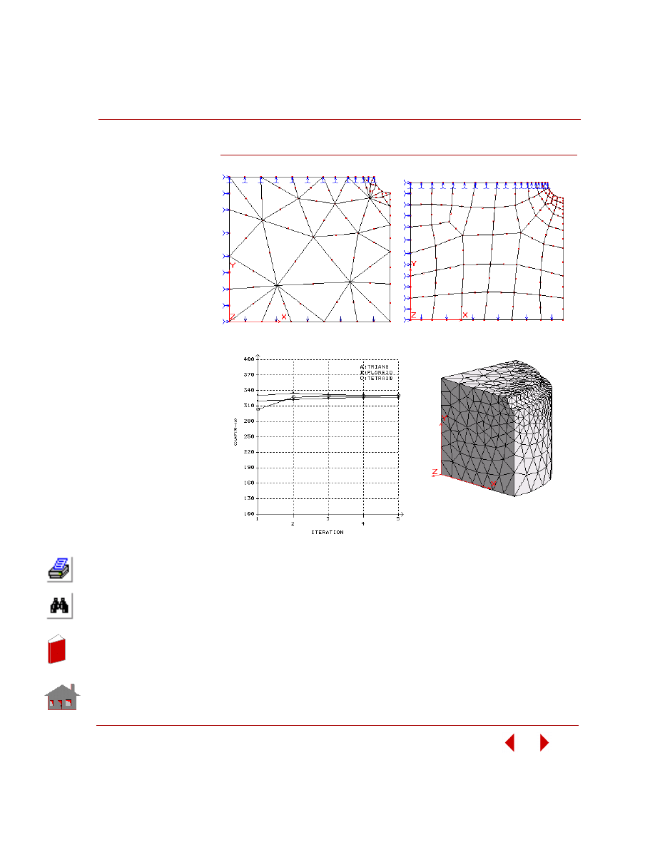
COSMOSM Basic FEA System
2-147
Part 2 Verification Problems
Figure S95-2: Finite Element Model with Different Element Types
S95A: TRIANG elements
S95B: PLANE2D elements
S95C: TETRA10 elements
Convergence Plots Using Different Element Types
In
de
x
In
de
x
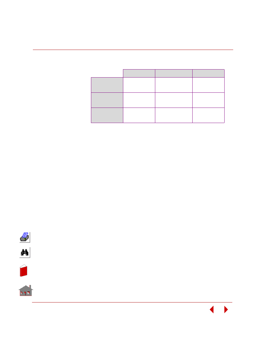
Chapter 2 Linear Static Analysis
2-148
COSMOSM Basic FEA System
COMPARISON OF RESULTS:
REFERENCE:
Walter D. Pilkey, “Formulas For Stress, Strain, and Structural Matrices,” Wiley-
Interscience Publication, JohnWiley & Sons, Inc., 1994, pp. 267.
Theory
COSMOSM
Relative Error
Max. Stress in Y-
Direction
(TRIANG)
305 psi
337 psi (p-order = 4 )
10.5%
Max. Stress in Y-
Direction
(PLANE2D)
305 psi
333 psi (p-order = 8)
9.2%
Max. Stress in Y-
Direction
(TETRA10)
305 psi
339 psi (p-order = 5)
10.5%
In
de
x
In
de
x

COSMOSM Basic FEA System
3-1
3
Modal (Frequency)
Analysis
Introduction
This chapter contains verification problems to demonstrate the accuracy of the
Modal Analysis module DSTAR.
List of Natural Frequency Verification Problems
F1:Natural Frequencies of a Two-Mass Spring System
F2: Frequencies of a Cantilever Beam
F3: Frequency of a Simply Supported Beam
F4: Natural Frequencies of a Cantilever Beam
F5: Frequency of a Cantilever Beam with Lumped Mass
F6: Dynamic Analysis of a 3D Structure
F7A, F7B: Dynamic Analysis of a Simply Supported Plate
F8: Clamped Circular Plate
F9: Frequencies of a Cylindrical Shell
F10: Symmetric Modes and Natural Frequencies of a Ring
F11A, F11B: Eigenvalues of a Triangular Wing
F12: Vibration of an Unsupported Beam
In
de
x
In
de
x
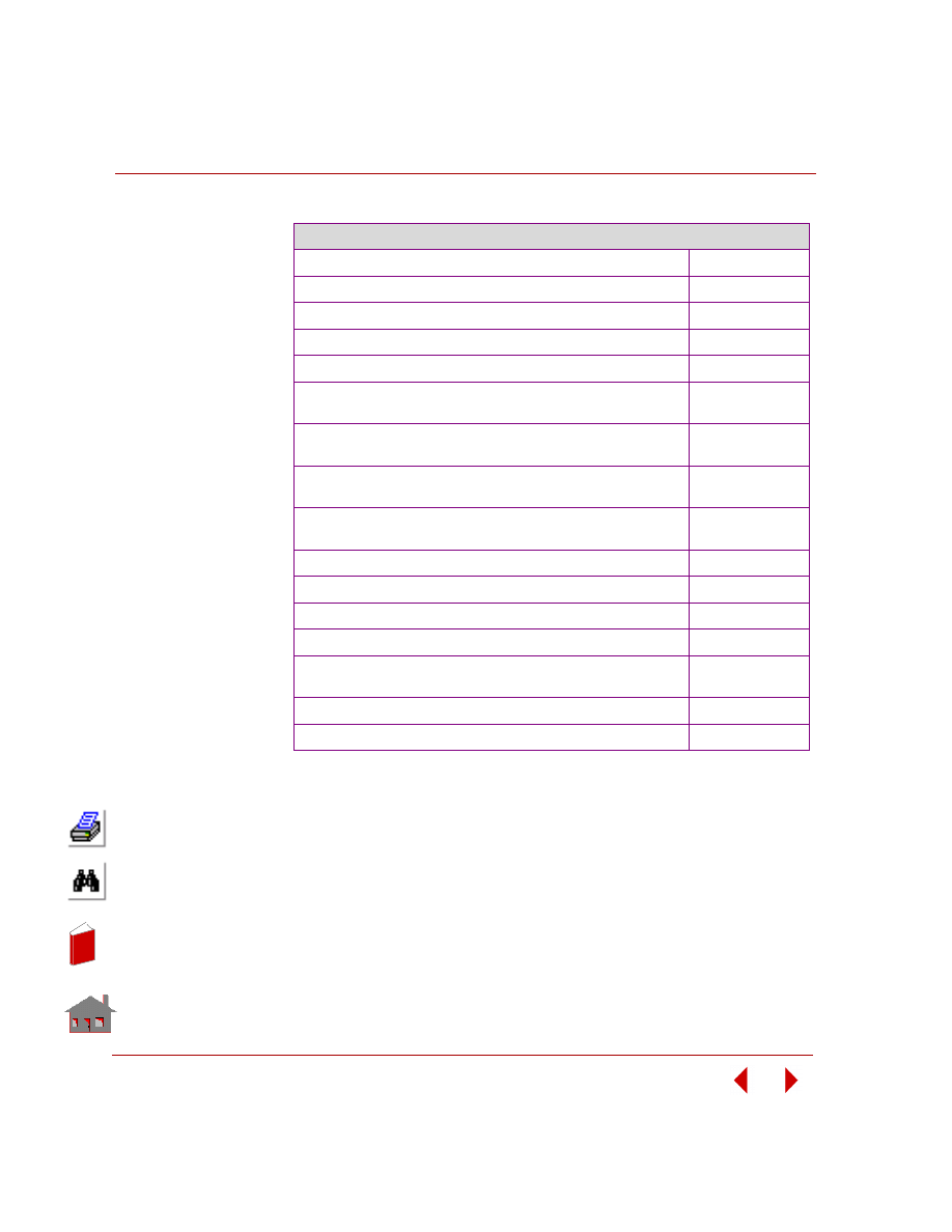
Chapter 3 Modal (Frequency) Analysis
3-2
COSMOSM Basic FEA System
List of Natural Frequency Verification Problems (Concluded)
F13: Frequencies of a Solid Cantilever Beam
F14: Natural Frequency of Fluid
F16A, F16B: Vibration of a Clamped Wedge
F17: Lateral Vibration of an Axially Loaded Bar
F18: Simply Supported Rectangular Plate
F19: Lowest Frequencies of Clamped Cylindrical Shell for
Harmonic No. = 6
F20A, F20B, F20C, F20D, F20E, F20F, F20G, F20H: Dynamic
Analysis of Cantilever Beam
F21: Frequency Analysis of a Right Circular Canal of Fluid
with Variable Depth
F22: Frequency Analysis of a Rectangular Tank of Fluid with
Variable Depth
F23: Natural Frequency of Fluid in a Manometer
F24: Modal Analysis of a Piezoelectric Cantilever
F25: Frequency Analysis of a Stretched Circular Membrane
F26: Frequency Analysis of a Spherical Shell
F27A, F27B: Natural Frequencies of a Simply-Supported
Square Plate
F28: Cylindrical Roof Shell
F29: Frequency Analysis of a Spinning Blade
In
de
x
In
de
x
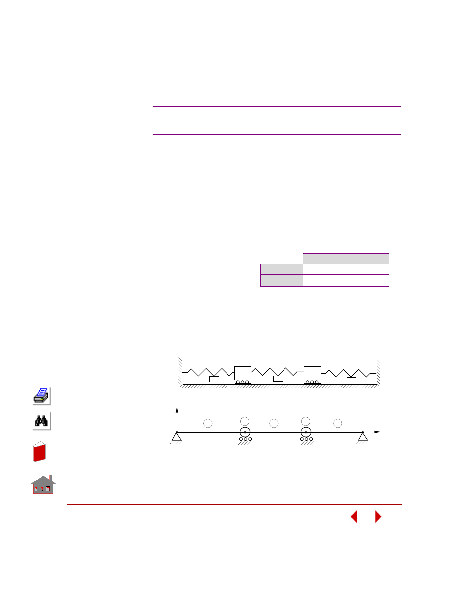
COSMOSM Basic FEA System
3-3
Part 2 Verification Problems
TYPE:
Mode shape and frequency, truss and mass element (TRUSS3D, MASS).
REFERENCES:
Thomson, W. T., “Vibration Theory and Application,” Prentice-Hall, Inc.,
Englewood Cliffs, New Jersey, 2nd printing, 1965, p. 163.
PROBLEM:
Determine the normal modes and natural frequencies of the system shown below for
the values of the masses and the springs given.
MODELING HINTS:
Truss elements with zero density are used as springs. Two dynamic degrees of
freedom are selected at nodes 2 and 3 and masses are input as concentrated masses
at nodes 2 and 3.
Figure F1-1
F1: Natural Frequencies of a
Two-Mass Spring System
GIVEN:
m
2
= 2m
1
= 1 lb-sec
2
/in
k
2
= k
1
= 200 lb/in
k
c
= 4k
1
= 800 lb/in
COMPARISON OF RESULTS:
F
1
, Hz
F
2,
Hz
Theory
2.581
8.326
COSMOSM
2.581
8.326
Problem Sketch
2
k
1
k
c
k
m
1
m
2
1st
D.O.F.
2nd
D.O.F.
X
Finite Element Model
1
2
3
4
1
2
3
Y
5
4
In
de
x
In
de
x
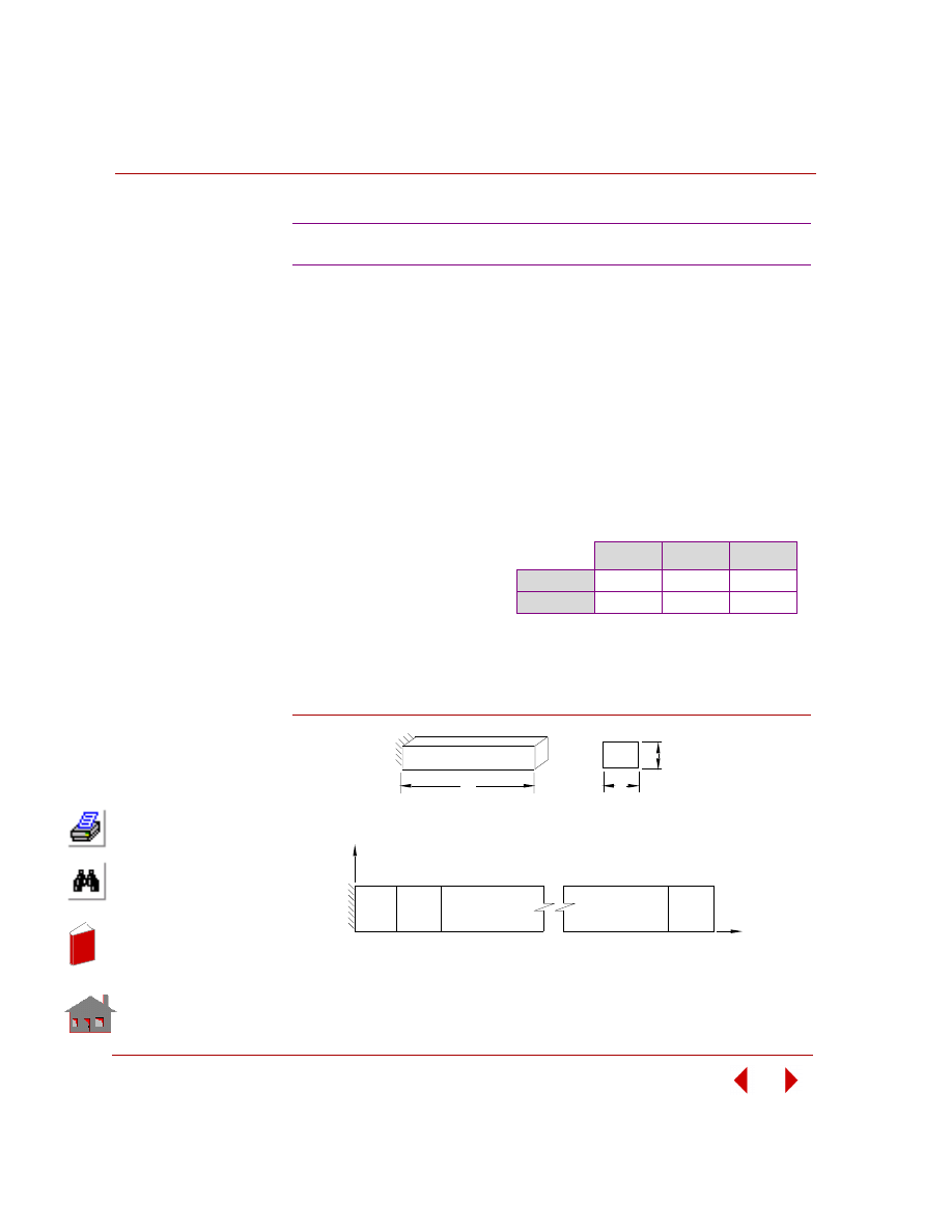
Chapter 3 Modal (Frequency) Analysis
3-4
COSMOSM Basic FEA System
TYPE:
Mode shape and frequency, plane element (PLANE2D).
REFERENCE:
Flugge, W., “Handbook of Engineering Mechanics,” McGraw-Hill Book Co.,
Inc.,
New York, 1962, pp. 61-6, 61-9.
PROBLEM:
Determine the fundamental frequency, f, of the cantilever beam of uniform cross
section A.
Figure F2-1
F2: Frequencies of a Cantilever Beam
GIVEN:
E
= 30 x 10
6
psi
L
= 50 in
h
= 0.9 in
b
= 0.9 in
A
= 0.81 in
2
ν
= 0
ρ
= 0.734E-3 lb sec
2
/in
4
COMPARISON OF RESULTS
F
1
, Hz
F
2
, Hz
F
3
, Hz
Theory
11.79
74.47
208.54
COSMOSM
11.72
73.35
206.68
y
x
Finite Element Model
L
Problem Sketch
Front View
Cross Section
b
h
In
de
x
In
de
x
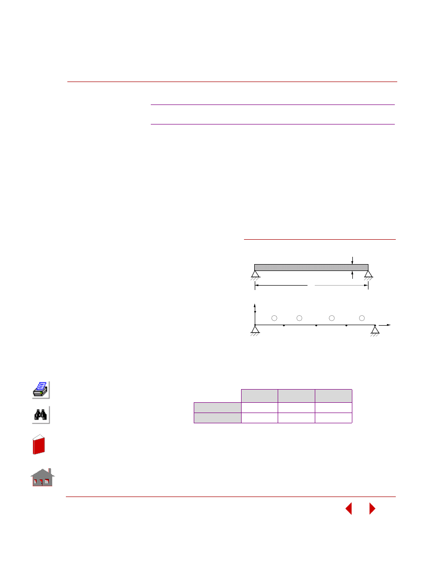
COSMOSM Basic FEA System
3-5
Part 2 Verification Problems
TYPE:
Mode shapes and frequencies, beam element (BEAM3D).
REFERENCE:
Thomson, W. T., “Vibration Theory and Applications,” Prentice-Hall, Inc.,
Englewood Cliffs, New Jersey, 2nd printing, 1965, p. 18.
PROBLEM:
Determine the fundamental frequency, f, of the simply supported beam of uniform
cross section A.
GIVEN:
E
= 30 x 10
6
psi
L
= 80 in
ρ
= 0.7272E-3 lb-sec
2
/in
4
A
= 4 in
2
I
= 1.3333 in
4
h
= 2 in
ANALYTICAL
SOLUTION:
F
i
=
(i
π)
2
(EI/mL
4
)
(1/2)
i
= Number of frequencies
COMPARISON OF RESULTS:
F3: Frequency of a Simply Supported Beam
F
1
, Hz
F
2
, Hz
F
3
, Hz
Theory
28.78
115.12
259.0
COSMOSM
28.78
114.31
242.7
Figure F3-1
2
1
3
4
1
2
3
Y
4
5
X
6
Finite Element Model
L
h
Problem Sketch
In
de
x
In
de
x
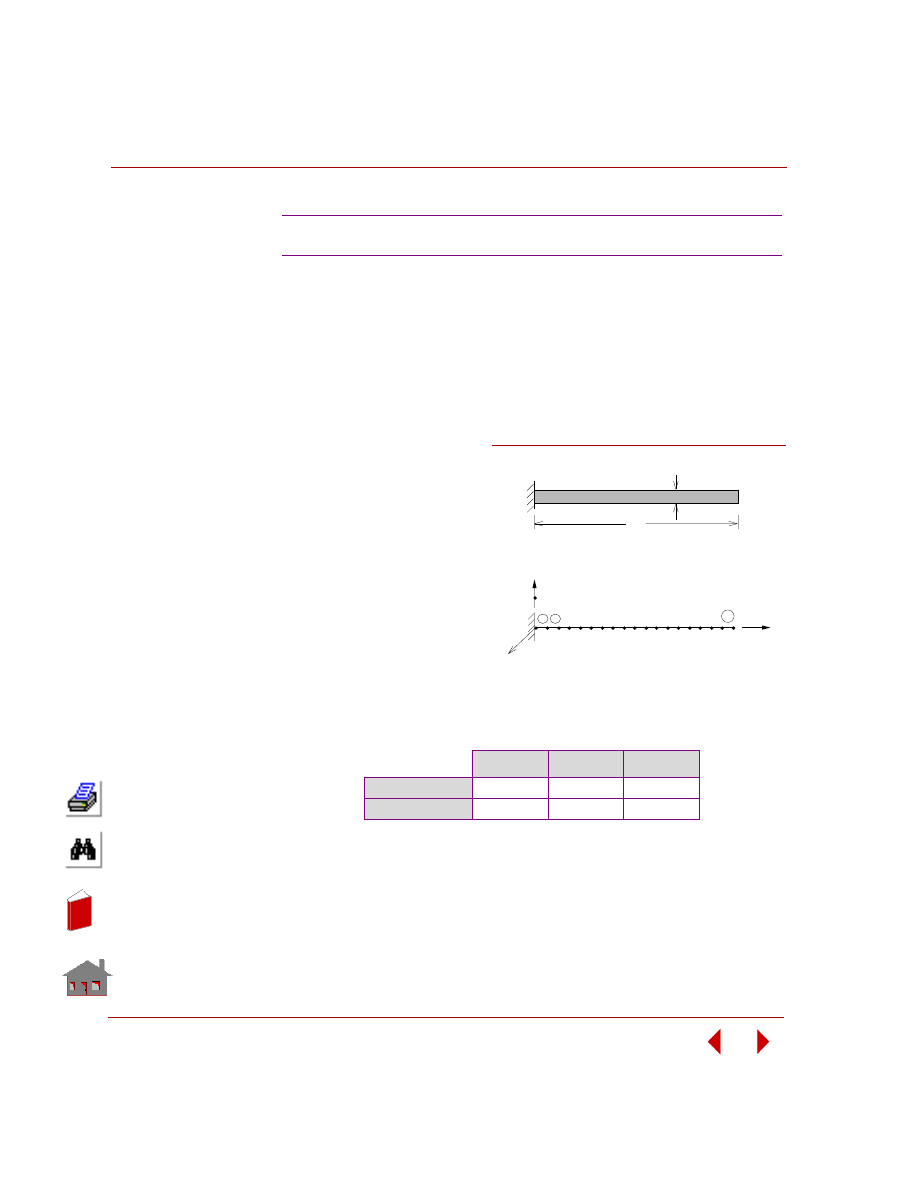
Chapter 3 Modal (Frequency) Analysis
3-6
COSMOSM Basic FEA System
TYPE:
Mode shapes and frequencies, beam element (BEAM3D).
REFERENCE:
Thomson, W. T., “Vibration Theory and Applications,” Prentice-Hall, Inc.,
Englewood Cliffs, New Jersey, 2nd printing, 1965, p. 278, Ex. 8.5-1, and p. 357.
PROBLEM:
Determine the first three
natural frequencies, f, of a
uniform beam clamped at
one end and free at the
other end.
GIVEN:
E
= 30 x 10
6
psi
I =
1.3333
in
4
A
= 4 in
2
h
= 2 in
L
= 80 in
ρ
= 0.72723E-3 lb sec
2
/in
4
COMPARISON OF RESULTS:
F4: Natural Frequencies of a Cantilever Beam
F
1
, Hz
F
2
, Hz
F
3
, Hz
Theory
10.25
64.25
179.9
COSMOSM
10.24
63.95
178.5
L
h
Problem Sketch
1 2 3 4
19
1 2
18
X
Z
Y
20
Finite Element Model
Figure F4-1
In
de
x
In
de
x
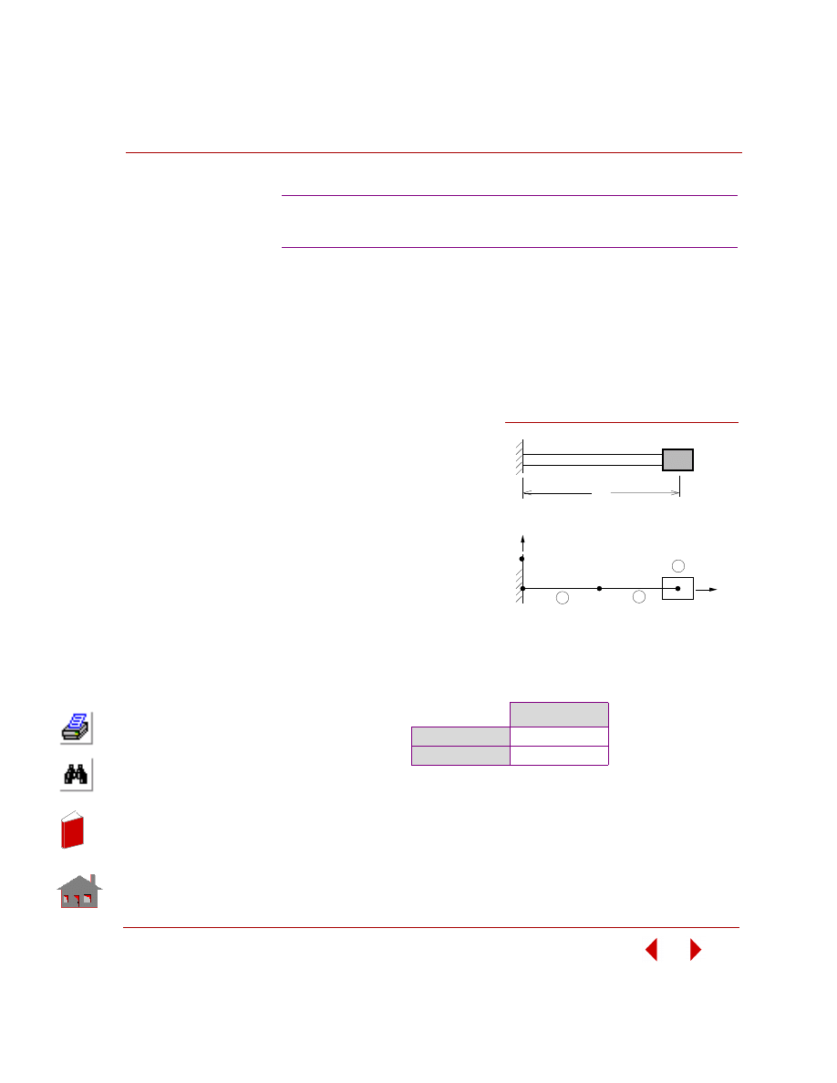
COSMOSM Basic FEA System
3-7
Part 2 Verification Problems
TYPE:
Mode shape and frequency, beam and mass elements (BEAM3D, MASS).
REFERENCE:
William, W. Seto, “Theory and Problems of Mechanical Vibrations,” Schaum’s
Outline Series, McGraw-Hill Book Co., Inc., New York, 1964, p. 7.
PROBLEM:
A steel cantilever beam of
length 10 in has a square cross-
section of 1/4 x 1/4 inch. A
weight of 10 lbs is attached to
the free end of the beam as
shown in the figure. Determine
the natural frequency of the
system if the mass is displaced
slightly and released.
GIVEN:
E
= 30 x 10
6
psi
W = 10 lb
L
= 10 in
COMPARISON OF RESULTS:
F5: Frequency of a Cantilever Beam
with Lumped Mass
F, Hz
Theory
5.355
COSMOSM
5.359
L
W
Problem Sketch
Y
X
1
2
3
1
3
4
2
Finite Element Model
Figure F5-1
In
de
x
In
de
x
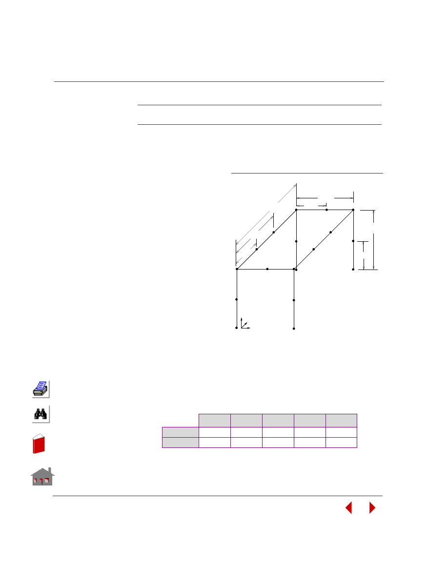
Chapter 3 Modal (Frequency) Analysis
3-8
COSMOSM Basic FEA System
TYPE:
Mode shapes and frequencies, pipe and mass elements (PIPE, MASS).
REFERENCE:
“ASME Pressure Vessel and
Piping 1972 Computer
Programs Verification,” Ed.
by I. S. Tuba and W. B.
Wright, ASME Publication
I-24, Problem 1.
PROBLEM:
Find the natural frequencies
and mode shapes of the 3D
structure given below.
GIVEN:
Each member is a pipe.
Outer diameter = 2.375 in
Thickness = 0.154 in
E
= 27.9 x 10
6
psi
ν
= 0.3
The masses are represented solely by lumped masses as shown in the figure.
M
1
= M
2
= M
4
= M
6
= M
7
= M
8
= M
9
= M
11
= M
13
= M
14
= 0.00894223 lb sec
2
/in
M
3
= M
5
= M
10
= M
12
= 0.0253816 lb sec
2
/in
COMPARISON OF RESULTS:
F6: Dynamic Analysis of a 3D Structure
F
1
, Hz
F
2
, Hz
F
3
, Hz
F
4
, Hz
F
5
, Hz
Theory
111.5
115.9
137.6
218.0
404.2
COSMOSM
111.2
115.8
137.1
215.7
404.2
8.625
8.625
17.25
18.625
10.0
18.625
27.25
x
z
y
Problem Sketch and Finite Element Model
Figure F6-1
In
de
x
In
de
x
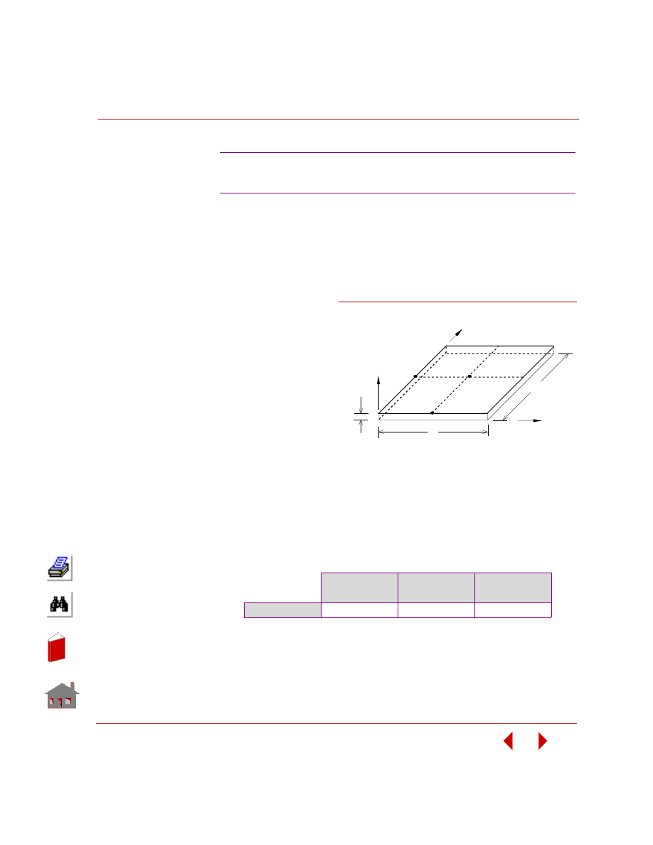
COSMOSM Basic FEA System
3-9
Part 2 Verification Problems
TYPE:
Mode shapes and frequencies, shell elements (SHELL4 and SHELL6).
REFERENCE:
Leissa, A.W. “Vibration of Plates,” NASA, sp-160, p. 44.
PROBLEM:
Obtain the first natural
frequency for a simply
supported plate.
GIVEN:
E
= 30,000 kips
ν
= 0.3
h
= 1 in
a
= b = 40 in
ρ
= 0.003 kips sec
2
/in
4
NOTE:
Due to double symmetry in geometry and the required mode shape, a quarter of the
plate is taken for modeling.
COMPARISON OF RESULTS
The first natural frequency of the plate is 5.94 Hz.
F7A, F7B: Dynamic Analysis of a Simply
Supported Plate
F7A: SHELL4
F7B: SHELL6
(Curved)
F7B: SHELL6
(Assembled)
COSMOSM
5.93 Hz
5.94 Hz
5.93
b
Z
Y
X
h
a
Problem Sketch and Finite Element Model
Figure F7-1
In
de
x
In
de
x
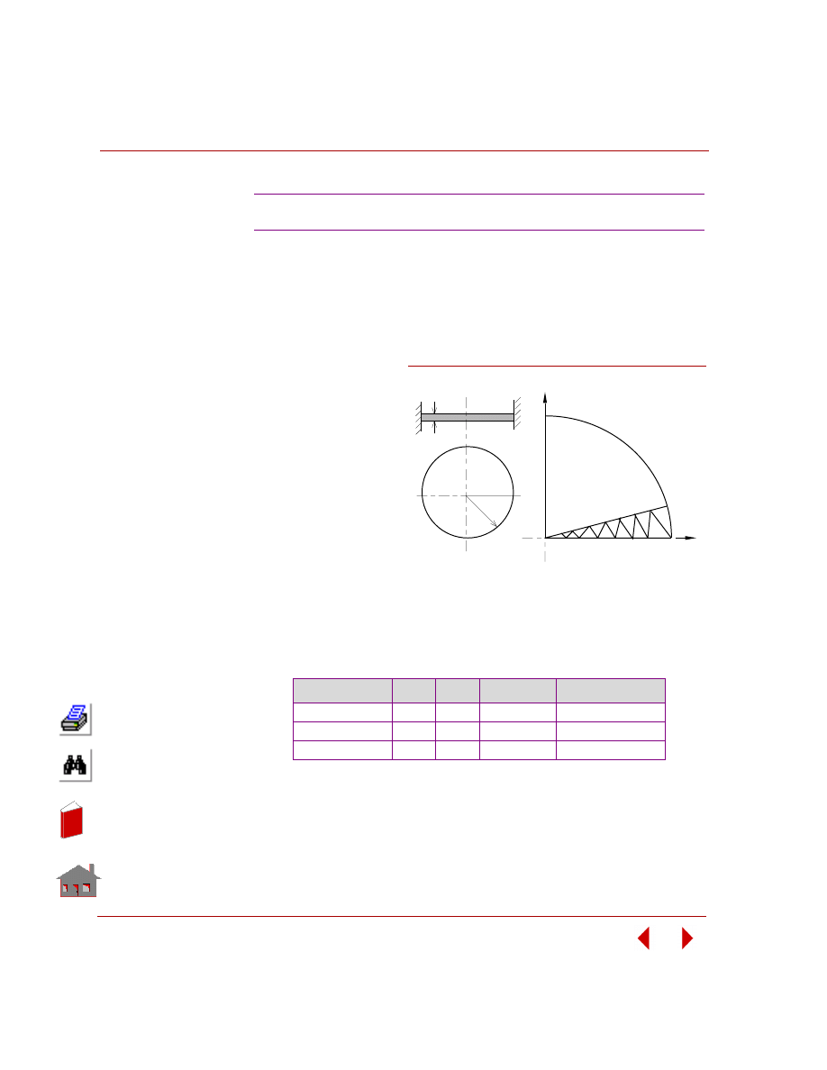
Chapter 3 Modal (Frequency) Analysis
3-10
COSMOSM Basic FEA System
TYPE:
Mode shapes and frequencies, thick shell element (SHELL3T).
REFERENCE:
Leissa A.W., “Vibration of Plates,” NASA sp-160, p. 8.
PROBLEM:
Obtain the first three
natural frequencies.
GIVEN:
E = 30 x 10
6
psi
ν = 0.3
ρ = 0.00073 (lb/in
4
) sec
2
R = 40 in
t = 1 in
NOTE:
Since a quarter of the plate is used for modeling, the second natural frequency is not
symmetric (s = 0, n = 1) and will not be calculated. This is an example to show that
symmetry should be used carefully.
COMPARISON OF RESULTS:
F8: Clamped Circular Plate
Frequency No.
s
*
n
*
Theory (Hz)
COSMOSM (Hz)
1
0
0
62.30
62.40
2
0
2
212.60
212.53
3
1
0
242.75
240.30
s* refers to the number of nodal circles
n* refers to the number of nodal diameters
Finite Element Model
Y
X
R
t
Problem Sketch
C
L
Figure F8-1
In
de
x
In
de
x
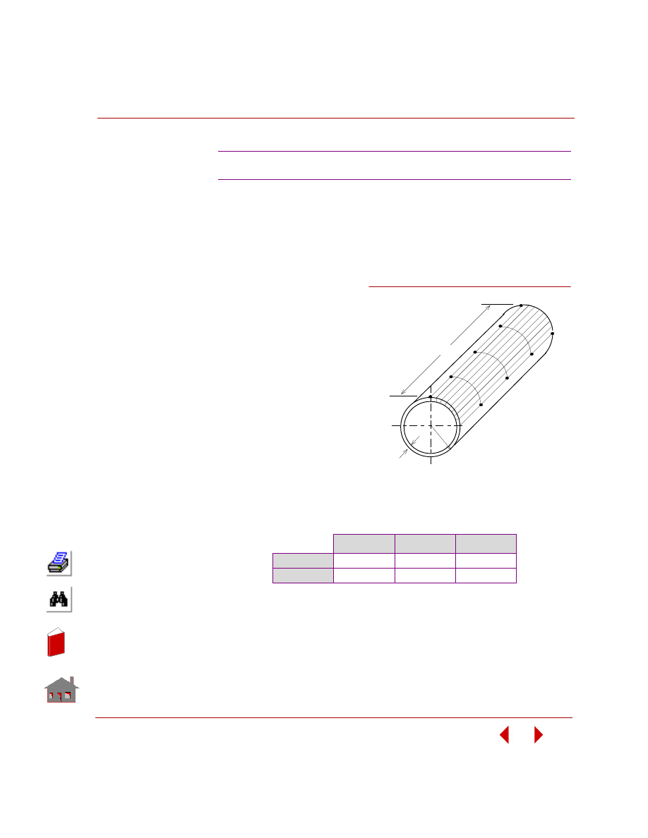
COSMOSM Basic FEA System
3-11
Part 2 Verification Problems
TYPE:
Mode shapes and frequencies, shell element (SHELL4).
REFERENCE:
Kraus, “Thin Elastic Shells,” John Wiley & Sons, Inc., p. 307.
PROBLEM:
Determining the first three
natural frequencies.
GIVEN:
E
= 30 x 10
6
psi
ν
= 0.3
ρ
= 0.00073 (lb-sec
2
)/in
4
L
= 12 in
R
= 3 in
t
= 0.01 in
NOTE:
Due to symmetry in geometry and the mode shapes of the first three natural
frequencies, 1/8 of the cylinder is considered for modeling.
COMPARISON OF RESULTS:
F9: Frequencies of a Cylindrical Shell
F
1
, Hz
F
2
, Hz
F
3
, Hz
Theory
552
736
783
COSMOSM
553.69
718.50
795.60
t
R
Problem Sketch
and Finite Element Model
L
Figure F9-1
In
de
x
In
de
x
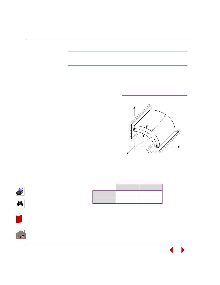
Chapter 3 Modal (Frequency) Analysis
3-12
COSMOSM Basic FEA System
TYPE:
Mode shapes and frequencies, shell element (SHELL4).
REFERENCE:
Flugge, W. “Handbook of
Engineering Mechanics,” First
Edition, McGraw-Hill, New York,
p. 61-19.
PROBLEM:
Determine the first two natural
frequencies of a uniform ring in
symmetric case.
GIVEN:
E
= 30E6 psi
ν
= 0
L
= 4 in
h
= 1 in
R
= 1 in
ρ
= 0.25E-2 (lb sec
2
)/in
4
COMPARISON OF RESULTS:
F10: Symmetric Modes and Natural
Frequencies of a Ring
F
1
, Hz
F
2
, Hz
Theory
135.05
735.14
COSMOSM
134.92
723.94
Z
h
L
Y
X
R
Problem Sketch
Figure F10-1
In
de
x
In
de
x
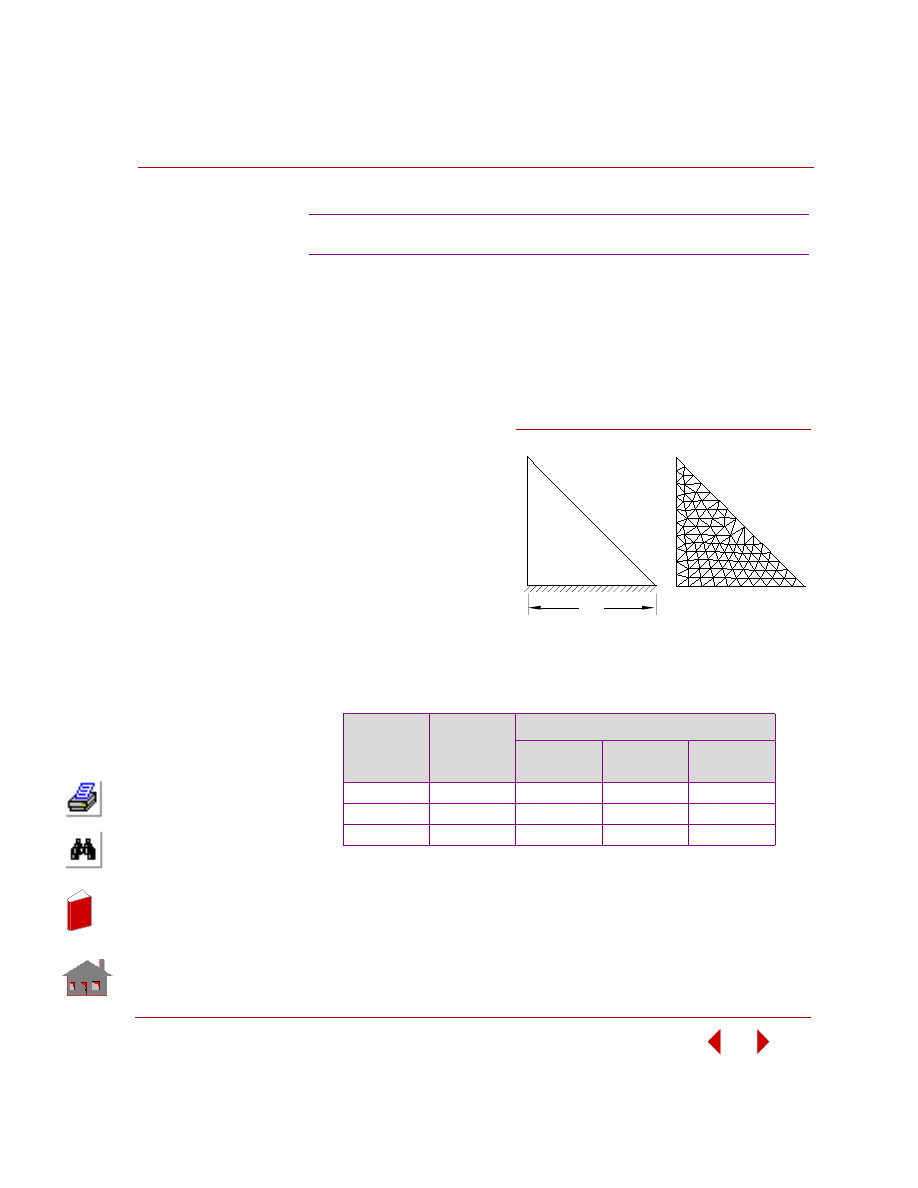
COSMOSM Basic FEA System
3-13
Part 2 Verification Problems
TYPE:
Mode shapes and frequencies, triangular shell elements (SHELL3 and SHELL6).
REFERENCE:
“ASME Pressure Vessel and Piping 1972 Computer Programs Verification,” ed. by
I. S. Tuba and W. B. Wright, ASME Publication I-24, Problem 2.
PROBLEM:
Calculate the natural
frequencies of a triangular
wing as shown in the figure.
GIVEN:
E
= 6.5 x 10
6
psi
ν
= 0.3541
ρ
= 0.166E-3 lb sec
2
/in
4
L
= 6 in
Thickness = 0.034 in
COMPARISON OF RESULTS:
Natural Frequencies (Hz):
F11A, F11B: Eigenvalues of a Triangular Wing
Frequency
No.
Reference
COSMOSM
SHELL3
SHELL6
(Curved)
SHELL6
(Assembled)
1
55.9
55.8
56.137
55.898
2
210.9
206.5
212.708
210.225
3
293.5
285.5
299.303
291.407
Finite Element Model
Problem Geometry
L
Figure F11-1
In
de
x
In
de
x
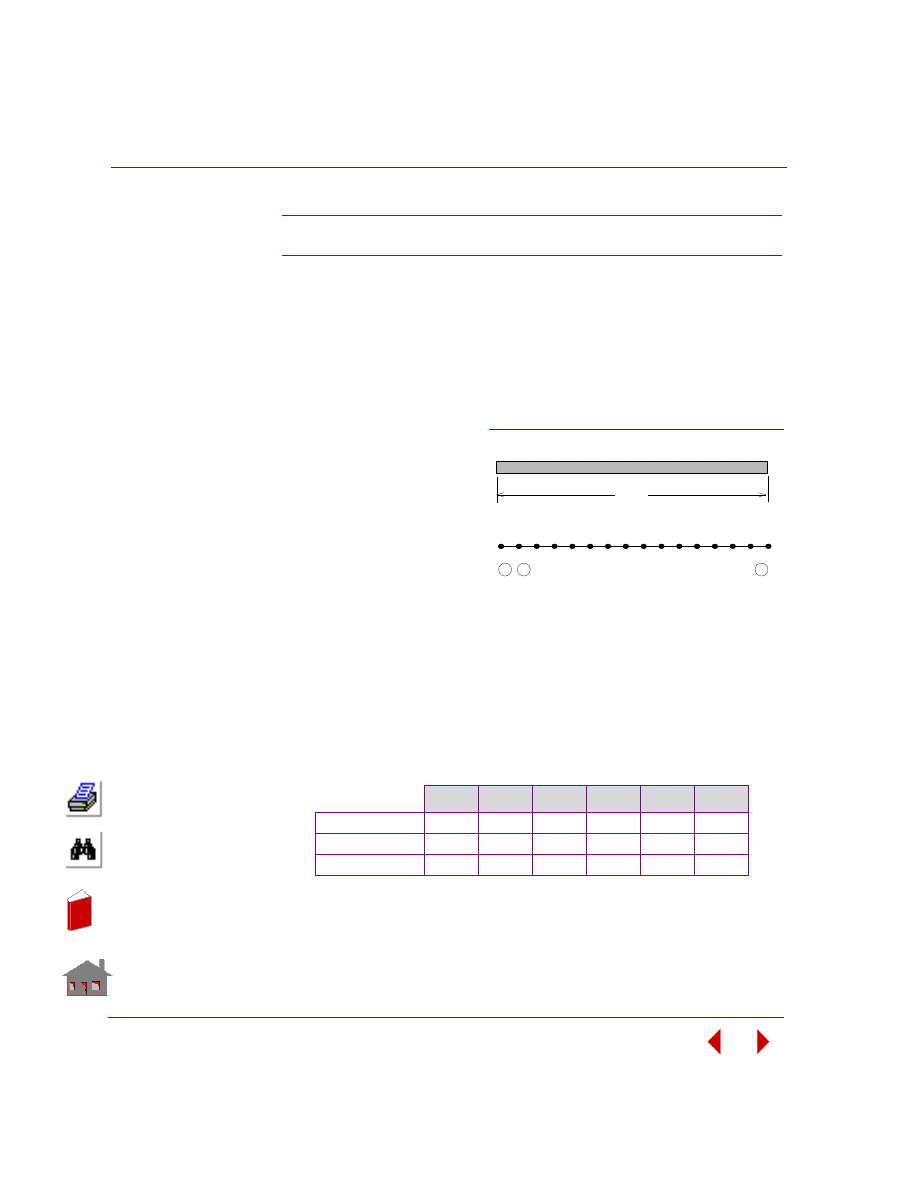
Chapter 3 Modal (Frequency) Analysis
3-14
COSMOSM Basic FEA System
TYPE:
Mode shapes and frequencies, rigid body modes, beam element (BEAM3D).
REFERENCE:
Timoshenko, S. P., Young, O. H., and Weaver, W., “Vibration Problems in
Engineering,” 4th ed., John Wiley and Sons, New York, 1974, pp. 424-425.
PROBLEM:
Determine the elastic and
rigid body modes of vibration
of the unsupported beam
shown below.
GIVEN:
L
= 100 in
E
= 1 x 10
8
psi
r
= 0.1 in
ρ
= 0.2588E-3 lb sec
2
/in
4
ANALYTICAL SOLUTION:
The theoretical solution is given by the roots of the equation Cos KL Cosh KL = 1
and the frequencies are given by:
COMPARISON OF RESULTS:
NOTE:
First two modes are rigid body modes.
F12: Vibration of an Unsupported Beam
f
i
= K
i
2
(EI/
ρA)
(1/2)
/(2
π)
i
= Number of natural frequencies
K
i
= (i + 0.5)
π/L
A
= area of cross-section
ρ
= Mass Density
Mode 1
Mode 2
Mode 3
Mode 4
Mode 5
Mode 6
Theory F, Hz
0
0
11.07
30.51
59.81
98.86
Theory (ki)
(0)
(0)
(4.73)
(7.853)
(10.996) (14.137)
COSMOSM F, Hz
0
0
10.92
29.82
57.94
94.94
Figure F12-1
1
1
2
3
15 16
2
Finite Element Model
15
L
Problem Sketch
In
de
x
In
de
x
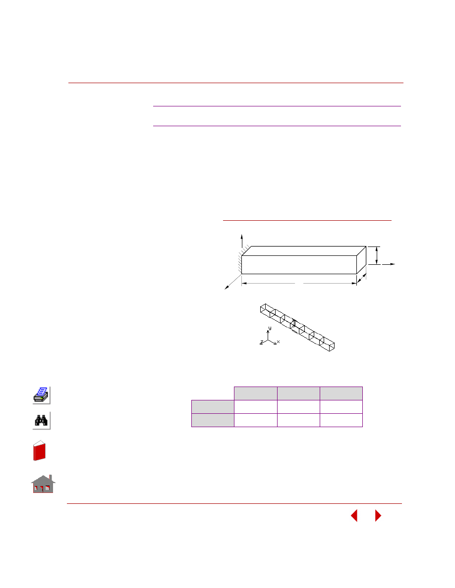
COSMOSM Basic FEA System
3-15
Part 2 Verification Problems
TYPE:
Mode shapes and frequencies, hexahedral solid element (SOLID).
REFERENCE:
Thomson, W. T., “Vibration Theory and Applications,” Prentice-Hall, Inc.,
Englewood Cliffs, N. J., 2nd printing, 1965, p.275, Ex. 8.5-1, and p. 357.
PROBLEM:
Determine the first
three natural
frequencies of a
uniform beam
clamped at one
end and free at
the other end.
GIVEN:
E
= 30 x 10
6
psi
a
= 2 in
b
= 2 in
L
= 80 in
ρ
= 0.00072723
lb-sec
2
/in
4
COMPARISON OF RESULTS:
F13: Frequencies of a Solid Cantilever Beam
F
1
, Hz
F
2
, Hz
F
3
, Hz
Theory
10.25
64.25
179.91
COSMOSM
10.24
63.95
178.38
L
x
y
z
Problem Sketch
b
a
Finite Element
Model
Figure F13-1
In
de
x
In
de
x
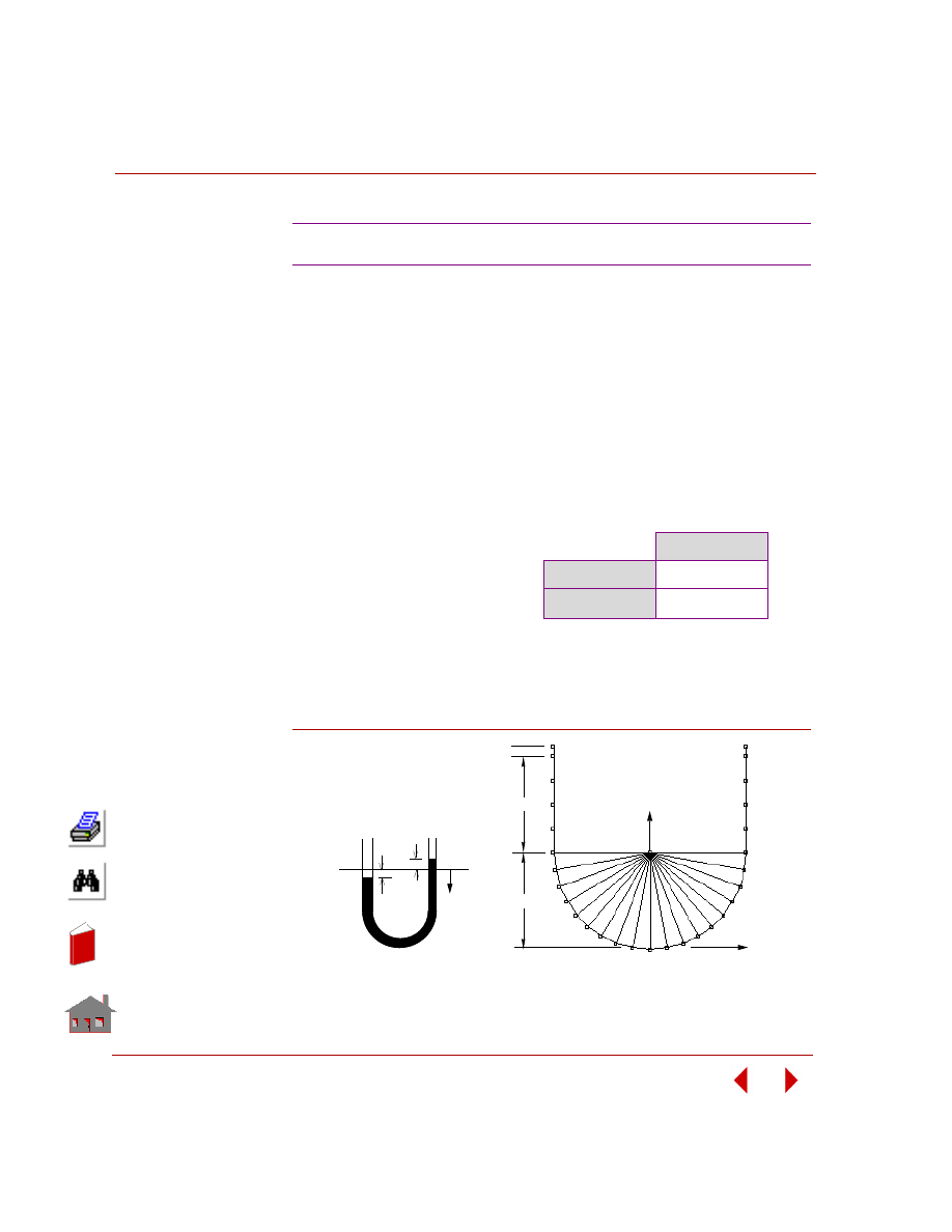
Chapter 3 Modal (Frequency) Analysis
3-16
COSMOSM Basic FEA System
TYPE:
Mode shapes and frequencies, truss elements (TRUSS2D).
REFERENCE:
William,
W.
Seto,
“Theory and Problems of Mechanical
Vibrations,”
Schaum’s
Outline Series, McGraw-Hill Book Co., Inc., New York, 1964, p. 7.
PROBLEM:
A manometer used in a fluid mechanics laboratory has a uniform bore of cross-
section area A. If a column of liquid of length L and weight density
ρ
is set into
motion, as shown in the figure, find the frequency of the resulting motion.
NOTE:
The mass of fluid is lumped at nodes 2 to 28. The boundary elements are applied at
nodes 6 to 24.
Figure F14-1
F14: Natural Frequency of Fluid
GIVEN:
COMPARISON OF RESULTS:
A
= 1 in
2
ρ = 9.614E-5 lb sec
2
/in
4
L
= 51.4159 in
E
= 1E5 psi
F, Hz
Theory
0.617
COSMOSM
0.617
y
y
y
Problem Sketch
Finite Element Model
1.0"
10"
X
Y
10"
In
de
x
In
de
x
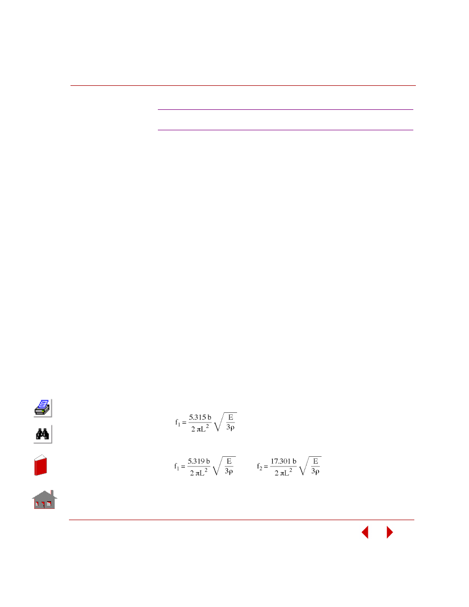
COSMOSM Basic FEA System
3-17
Part 2 Verification Problems
TYPE:
Mode shapes and frequencies, thick shell elements (SHELL3T, SHELL4T).
REFERENCE:
Timoshenko, S., and Young, D. H., “Vibration Problems in Engineering,” 3rd
Edition, D. Van Nostrand Co., Inc., New York, 1955, p. 392.
PROBLEM:
Determine the fundamental frequency of lateral vibration of a wedge shaped plate.
The plate is of uniform thickness t, base 3b, and length L.
GIVEN:
E
= 30 x10
6
psi
ρ
= 7.28E-4 lb sec
2
/in
4
t
= 1 in
b
= 2 in
L
= 16 in
MODELING HINTS:
Only in-plane (in x-y plane) frequencies along y-direction are considered. In order
to find better results, out-of-plane displacements (z-direction) are restricted.
The effect of different elements and meshes is also considered.
ANALYTICAL SOLUTION:
The first in-plane natural frequency calculated by:
Using approximate RITZ method, for first and second natural frequencies:
F16A, F16B: Vibration of a Clamped Wedge
In
de
x
In
de
x
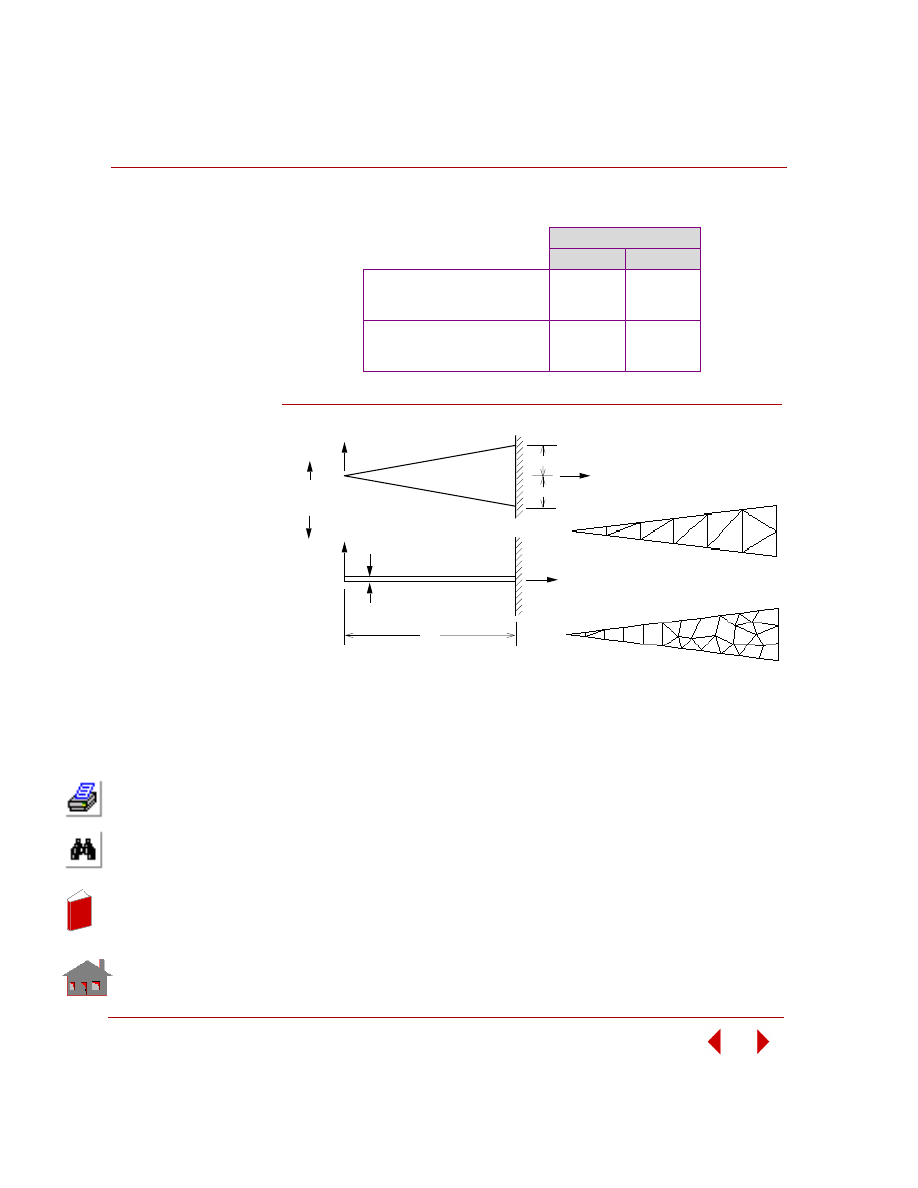
Chapter 3 Modal (Frequency) Analysis
3-18
COSMOSM Basic FEA System
COMPARISON OF RESULTS:
Figure F16A-1
Natural Frequency (Hz)
First
Second
Reference
Exact
Ritz
774.547
775.130
---
2521.265
COSMOSM
SHELL3T (F16A)
SHELL4T (F16B)
813.45
789.12
2280.78
2309.54
b
b
X
Y
Side View
Vibration
Direction
Fine Mesh SHELL4T
Elements
Coarse Mesh SHELL3T
Elements
Problem Sketch
Z
t
X
L
Plan
In
de
x
In
de
x
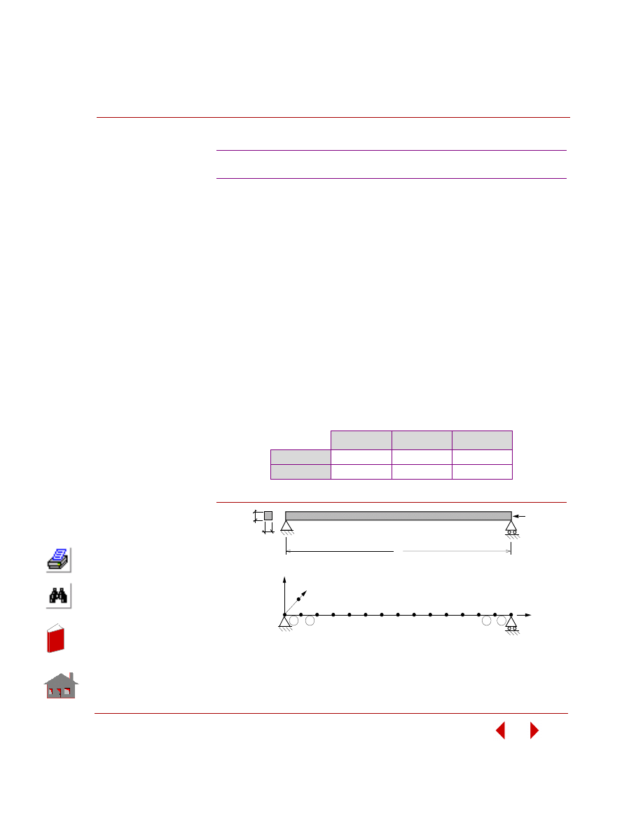
COSMOSM Basic FEA System
3-19
Part 2 Verification Problems
TYPE:
Mode shapes and frequencies, in-plane effects, beam elements (BEAM3D).
REFERENCE:
Timoshenko, S., and Young, D. H., “Vibration Problems in Engineering,” 3rd
Edition, D. Van Nostrand Co., Inc., New York, 1955, p. 374.
PROBLEM:
Determine the fundamental frequency of lateral vibration of a wedge shaped plate.
The plate is of uniform thickness t, base 3b, and length L.
GIVEN:
COMPARISON OF RESULTS:
Figure F17-1
F17: Lateral Vibration of an Axially Loaded Bar
E
= 30E6 psi
ρ
= 7.2792E-4 lb sec
2
/in
4
g
= 386 in/sec
2
b
= h = 2 in
L
= 80 in
P
= 40,000 lb
F
1
, Hz
F
2
, Hz
F
3
, Hz
Theory
17.055
105.32
249.39
COSMOSM
17.055
105.32
249.34
12
L
P
b
h
Problem Sketch
FInite Element Model
Z
1
2
3
14
1
2
13
13
12
X
Y
15
In
de
x
In
de
x
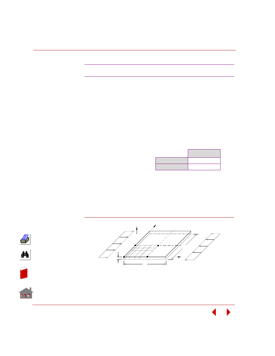
Chapter 3 Modal (Frequency) Analysis
3-20
COSMOSM Basic FEA System
TYPE:
Mode shapes and frequencies, in-plane effects, shell element (SHELL4).
REFERENCE:
Leissa, A.W., “Vibration of Plates,” NASA, p-160, p. 277.
PROBLEM:
Obtain the fundamental frequency of a simply supported plate with the effect of in-
plane forces. Nx = 33.89 lb/in applied at x = 0 and x = a.
NOTE:
Due to double symmetry in geometry, loads and the mode shape, a quarter plate is
taken for modeling.
Figure F18-1
F18: Simply Supported Rectangular Plate
GIVEN:
COMPARISON OF RESULTS:
E
= 30,000 psi
ν = 0.3
h
= 1 in
a
= b = 40 in
ρ
= 0.0003 (lb sec
2
)/in
4
P
= 33.89 psi
F, Hz
Theory
4.20
COSMOSM
4.19
Problem Sketch and Finite Element Model
Z
Y
X
h
b
a
P
P
In
de
x
In
de
x
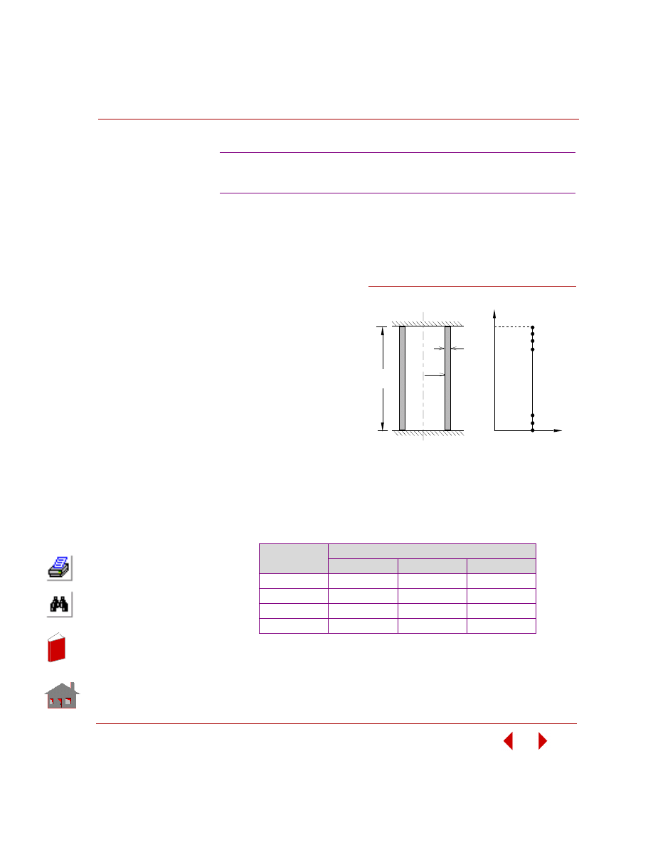
COSMOSM Basic FEA System
3-21
Part 2 Verification Problems
TYPE:
Mode shapes and frequencies, axisymmetric shell elements (SHELLAX).
REFERENCE:
Leissa, A. W., “Vibration of Shells,” NASA sp-288, p. 92-93 (1973).
PROBLEM:
To find the lowest natural
frequency of vibration for the
cylinder fixed at both ends.
GIVEN:
R
= 3 in
L
= 12 in
t
= 0.01 in
E
= 30 x 10
6
psi
ν
= 0.35
ρ
= 0.000730 lb sec
2
/in
4
Range of circumferential
harmonics (n) = 4 to 7
MODELING HINTS:
All the 21 nodes are spaced equally along the meridian of cylinder. The number of
circumferential harmonics (lobes) for each frequency analysis is to be specified and
lowest frequency is sought.
COMPARISON OF RESULTS:
F19: Lowest Frequencies of Clamped
Cylindrical Shell for Harmonic No. = 6
Harmonic No.
(n)
First Frequency (Hz)
Theory
Experiment
COSMOSM
(4) *
926
700
777.45
(5) *
646
522
592.6
(6) *
563
525
549.4
(7) *
606
592
609.7
* You need to re-execute the analysis by specifying these harmonic
numbers under the A_FREQUENCY command. The lowest natural
frequency is 549.6 Hz corresponding to harmonic number = 6.
21
1
Y
X
2
3
Finite Element Model
Problem Sketch
t
L
R
CL
CL
Figure F19-1
In
de
x
In
de
x
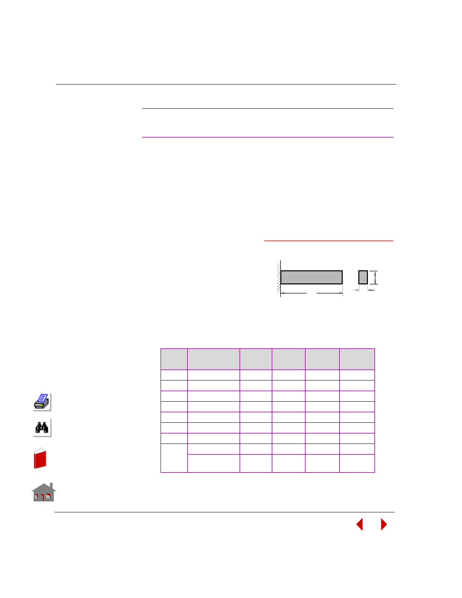
Chapter 3 Modal (Frequency) Analysis
3-22
COSMOSM Basic FEA System
TYPE:
Mode shapes and frequencies, multifield elements, 4- and 8-node PLANE2D,
SHELL4T, 6-node TRIANG, TETRA10, 8- and 20-node SOLID, TETRA4R, and
SHELL6.
PROBLEM:
Compare the first two natural frequencies of a cantilever beam modeled by each of
the above element types.
GIVEN:
E
= 10
7
psi
ρ
= 245 x 10
–3
lb-sec
2
/in
4
b
= 0.1 in
h
= 0.2 in
L
= 6 in
n
= 0.3
COMPARISON OF RESULTS:
The theoretical solutions for the first and second mode are: 181.17 and 1136.29 Hz.
F20A, F20B, F20C, F20D, F20E, F20F, F20G, F20H:
Dynamic Analysis of Cantilever Beam
Input
File
Element
1st Mode
Error (%)
2nd Mode
Error (%)
F20A
PLANE2D 4-node
180.71
0.2
1127.96
0.7
F20B
PLANE2D 8-node
181.15
0.0
1153.52
1.53
F20C
TRIANG 6-node
183.35
1.2
1182.90
4.1
F20D
TETRA10
183.10
1.0
1184.85
4.3
F20E
SOLID 8-node
181.64
0.2
1134.67
0.2
F20F
SOLID 20-node
179.72
0.8
1111.16
2.2
F20G
TETRA4R
190.24
5.1
1182.72
4.1
F20H
SHELL6 (Curved)
183.371
1.2
1182.87
4.1
SHELL6
(Assembled)
183.357
1.2
1182.54
4.1
b
L
h
Problem Sketch
Figure F20-1
In
de
x
In
de
x

COSMOSM Basic FEA System
3-23
Part 2 Verification Problems
TYPE:
Mode shapes and frequencies, fluid sloshing, plane strain elements (PLANE2D).
REFERENCE:
Budiansky, B., “Sloshing of Liquids in Circular Canals and Spherical Tank,” J.
Aerospace Sci, 27, p. 161-173, (1960).
PROBLEM:
A right circular canal with radius R is half-filled by an incompressible liquid (see
Figure F21-1). Determine the first two natural frequencies with mode shapes
antisymmetric about the Y-axis.
GIVEN
R
= 56.4 in
H/R = 0
ρ = 0.9345E-4 lb sec
2
/in
4
EX = 3E5 lb/in
2
Where:
EX = bulk modulus
NOTES:
1.
A small shear modulus SXY = EX is used to prevent numerical instability.
2.
The radial component of displacements (in local cylindrical coordinate system)
is constrained at the curved boundary in order to allow sloshing.
3.
The acceleration due to gravity (ACEL command) in the negative direction.
4.
PLANE2D plane strain elements are used to solve the current problem since the
mode shapes are independent of Z-direction coordinates.
5.
For non rectangular geometries, one can expect to obtain some natural
frequencies with no significant changes in the free surface profile. This situation
is analogous to the rigid modes of a solid structure. Therefore, a negative shift of
ω
2
is recommended to prevent this type of sloshing modes.
F21: Frequency Analysis of a Right Circular
Canal of Fluid with Variable Depth
In
de
x
In
de
x
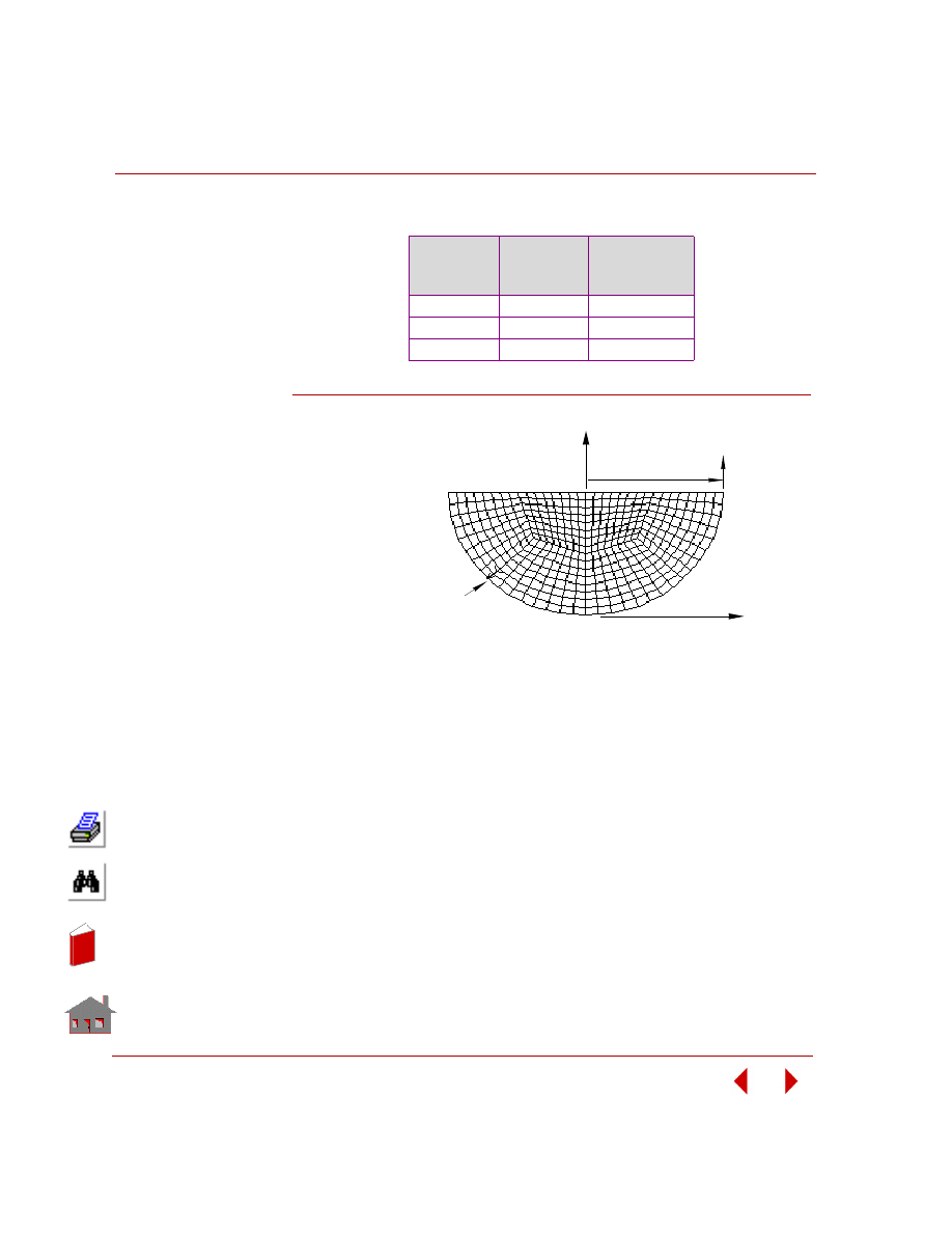
Chapter 3 Modal (Frequency) Analysis
3-24
COSMOSM Basic FEA System
COMPARISON OF RESULTS:
Figure F21-1
Mode
Number
Analytical
Solution
(Hz)
COSMOSM
(Hz)
1
0.4858
0.4875
2
Not Available
0.7269
3
0.9031
0.8976
Y
X
R
Free Surface
Constrain only the radial
component of displacement
to allow sloshing.
Finite Element Model
H
In
de
x
In
de
x
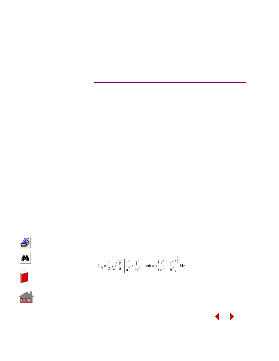
COSMOSM Basic FEA System
3-25
Part 2 Verification Problems
TYPE:
Mode shapes and frequencies, fluid sloshing, hexahedral solid (SOLID).
REFERENCE:
Lamb, H., “Hydrodynamics,” 6th edition, Dover Publications, Inc., New York,
1945.
PROBLEM:
A rectangular tank with dimensions A and B in X- and Z-directions is partially filled
by an incompressible liquid (see Figure F22-1). Determine the first two natural
frequencies.
GIVEN:
A
= 48 in
B
= 48 in
H
= 20 in
ρ
= 0.9345E-4 lb sec
2
/in
4
EX = 3E5 lb/in
2
Where:
EX = bulk modulus
NOTE:
Please refer to notes (1), (2), (3), (4) and (5) in Problem F21.
COMPARISON OF RESULTS:
The analytical solution for natural frequencies is as follows:
where i and j represent the order number in X- and Z-directions respectively.
F22: Frequency Analysis of a Rectangular
Tank of Fluid with Variable Depth
In
de
x
In
de
x
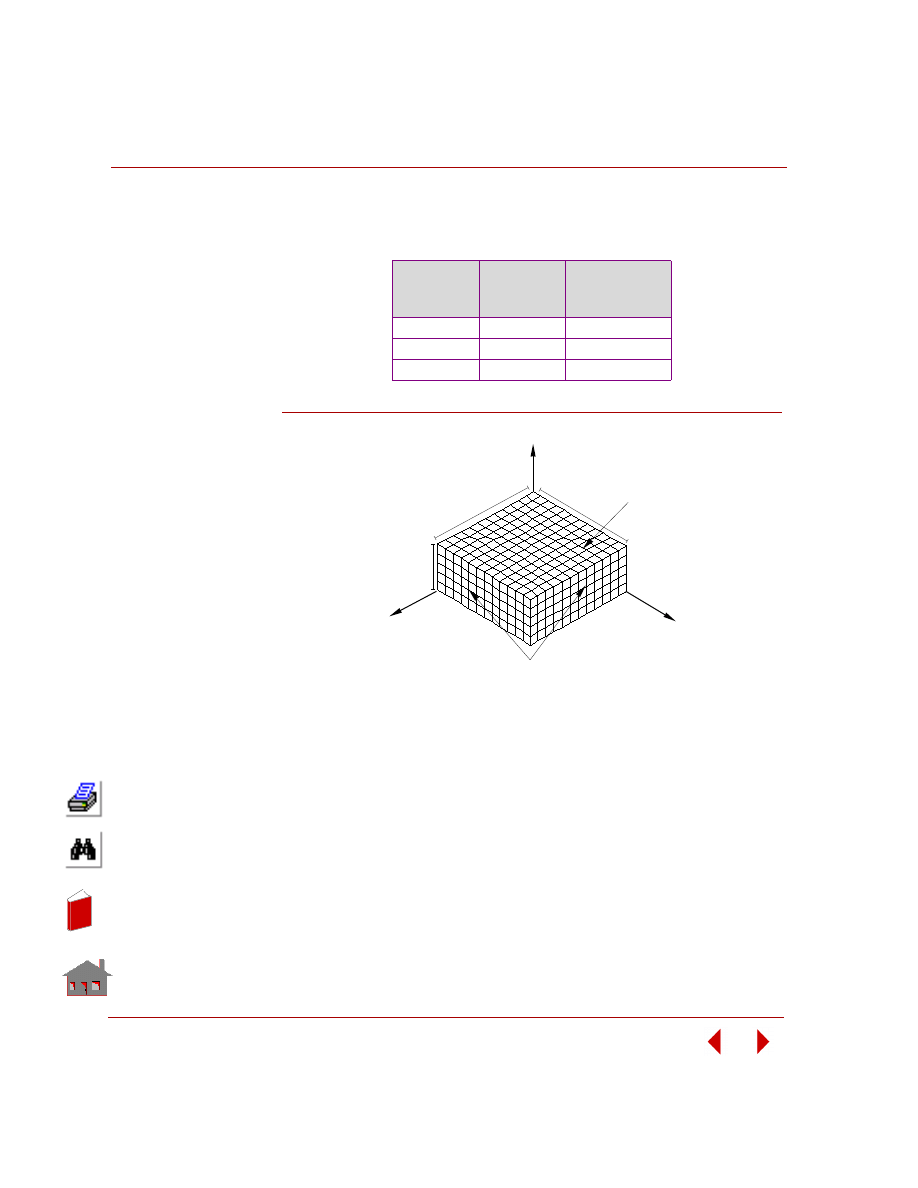
Chapter 3 Modal (Frequency) Analysis
3-26
COSMOSM Basic FEA System
The comparison of analytical solutions with those obtained using COSMOSM for
various values of i and j are tabulated below.
Figure F22-1
Frequency
Number
I / J
Analytical
Solution
(Hz)
COSMOSM
(Hz)
1 / 0
—
—
0 /1
0.7440
0.7422
1 / 2
0.9286
0.9199
X
Y
Z
Free Surface
Constrain the normal component of
displacement to allow sloshing.
A
B
H
Finite Element Model
In
de
x
In
de
x
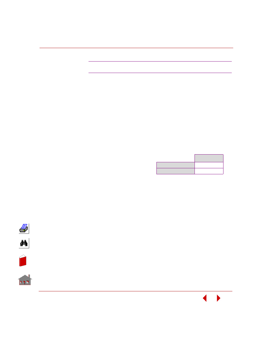
COSMOSM Basic FEA System
3-27
Part 2 Verification Problems
TYPE:
Mode shapes and frequencies, fluid sloshing, plane strain elements (PLANE2D).
REFERENCE:
William, W. Seto, “Theory and Problems of Mechanical Vibrations,” Schaum's
Outline Series, McGraw-Hill Book Co., Inc., New York, 1964, p. 7.
PROBLEM:
A manometer used in a fluid mechanics laboratory has a uniform bore of cross-
sectional area A. If a column of liquid of length L and weight density r is set into
motion as shown in the figures, find the frequency of the resulting motion.
NOTE:
A small shear modulus GXY = EX(1.0E-9) is used to prevent numerical instability.
Global and local constraints are applied normal to the boundary to prevent leaking
of the fluid. Acceleration due to gravity (ACEL command) in the negative y-
direction should be included for problems with free surfaces
F23: Natural Frequency of Fluid in a Manometer
GIVEN:
COMPARISON OF RESULTS:
A
= 0.5 in
2
ρ
= 0.9345E-4 lb sec
2
/in
4
L
= 26.4934 in (length of
fluid in the manometer)
EX = 3E5 lb/in
2
Where:
EX = bulk modulus
F, Hz
Analytical Solution *
0.8596
COSMOSM
0.8623
In
de
x
In
de
x
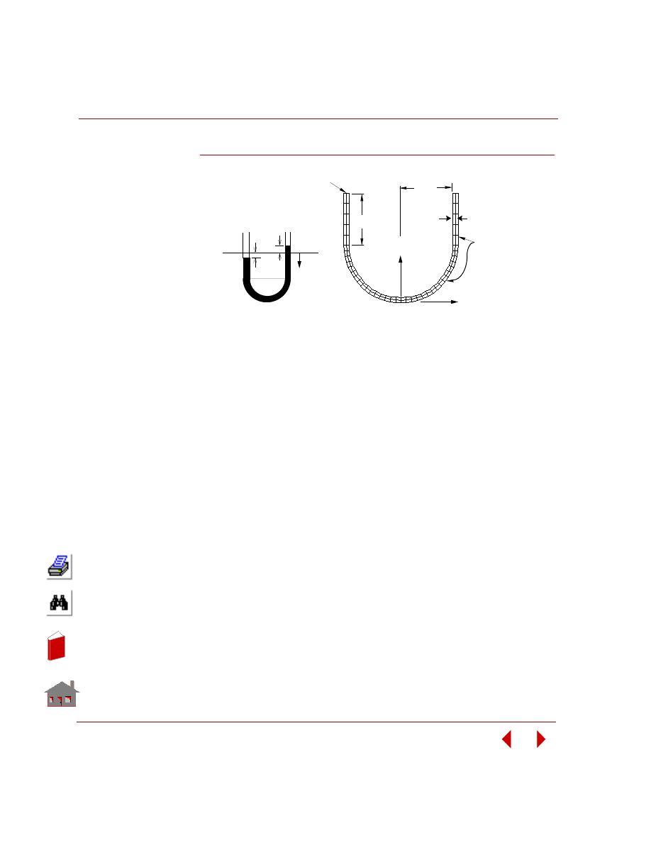
Chapter 3 Modal (Frequency) Analysis
3-28
COSMOSM Basic FEA System
Figure F23-1
y
y
y
Problem Sketch
Finite Element Model
X
Y
Constrain
displacement
components
normal to the
surface to allow
fluid sloshing
5 in
0.5 in
5 in
Free
Surface
In
de
x
In
de
x
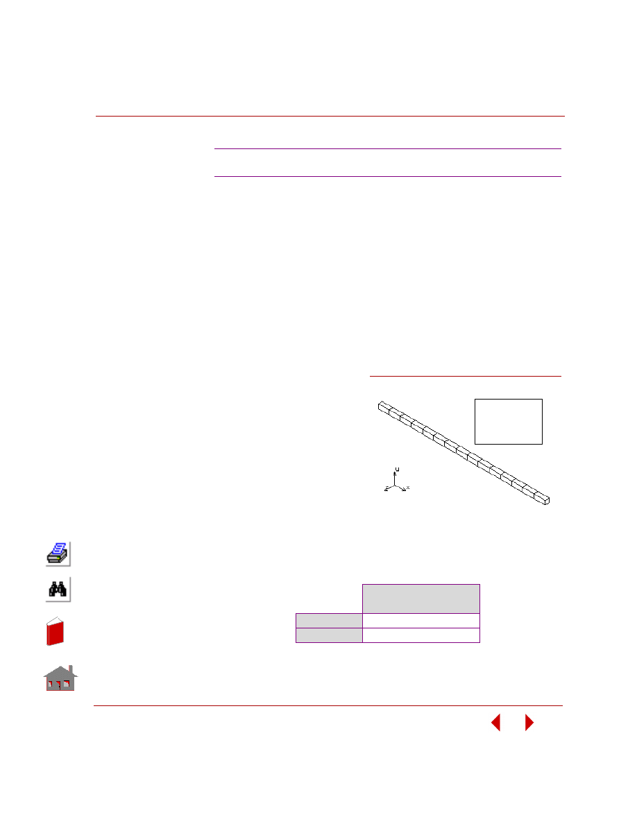
COSMOSM Basic FEA System
3-29
Part 2 Verification Problems
TYPE:
Mode shapes and frequencies using solid piezoelectric element (SOLIDPZ).
REFERENCE:
J. Zelenka, “Piezoelectric Resonators and their Applications”, Elsevier Science
Publishing Co., Inc., New York, 1986.
PROBLEM:
A piezoelectric transducer with a polarization direction along its longitudinal
direction has electrodes at two ends. Both electrodes are grounded to represent a
short-circuit condition. All non-prescribed voltage D.O.F.'s are condensed out after
assemblage of stiffness matrix. In this problem, the longitudinal mode of vibration
is under consideration.
GIVEN:
L
= 80 mm
b
= h = 2 mm
Density
= 727 Kg/m
3
NOTE:
To constrain voltage degrees of
freedom for piezoelectric applica-
tion, use the RX component of
displacement in the applicable constraint commands (DND, DCR, DSF, etc.). There
is no rotational degree of freedom for SOLID elements in COSMOSM.
COMPARISON OF RESULTS:
For the sixth mode of vibration in this problem (longitudinal mode):
F24: Modal Analysis of a Piezoelectric Cantilever
Sixth Mode of Vibration
(Longitudinal Mode)
Theory
690 Hz
COSMOSM
685 Hz
L = 80 mm
b = 2 mm
h = 2 mm
ρ
= 727 kg/cu m
Figure F24-1
In
de
x
In
de
x
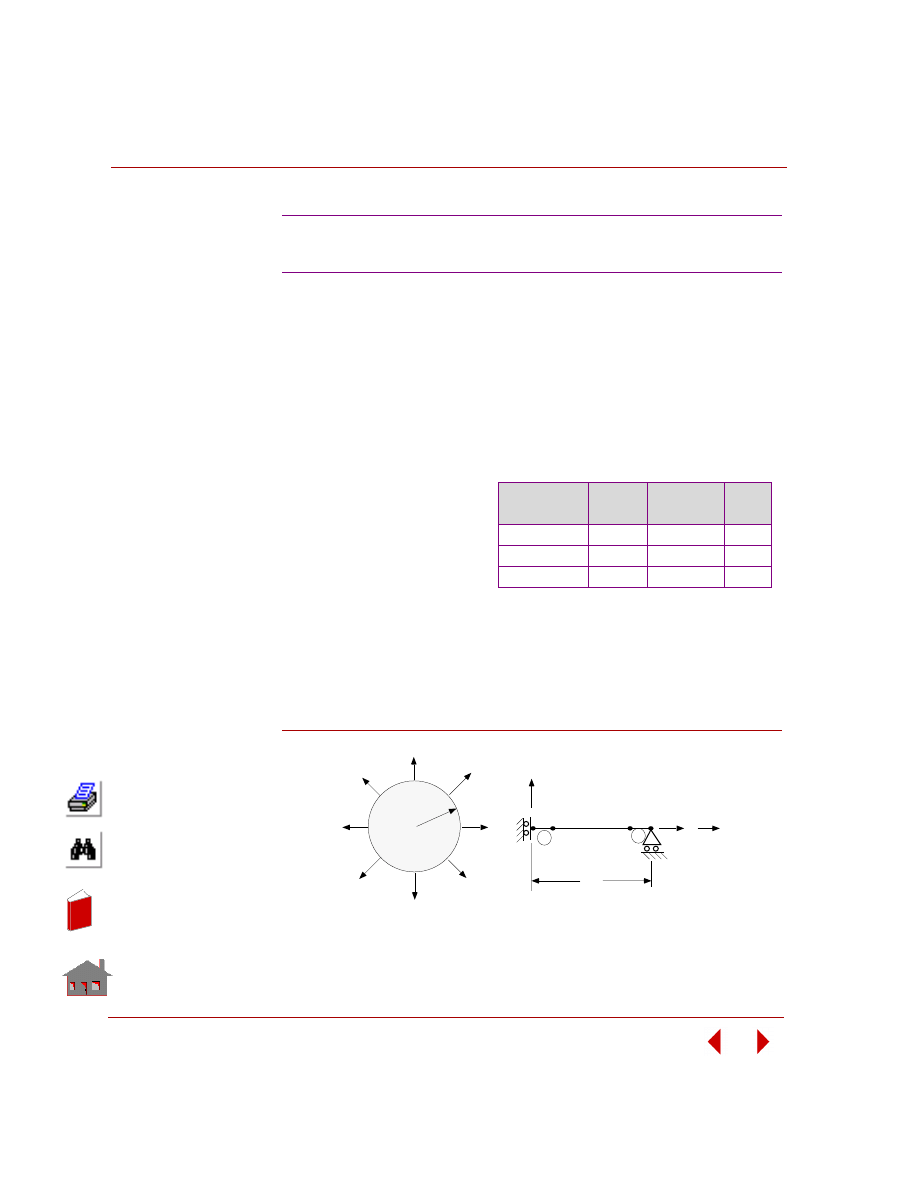
Chapter 3 Modal (Frequency) Analysis
3-30
COSMOSM Basic FEA System
TYPE:
Frequency analysis using the nonaxisymmetric mode shape option (SHELLAX).
REFERENCE:
Leissa, A. W., “Vibration of Shells,” NASA-P-SP-288, 1973.
PROBLEM:
Find the first three frequencies of a stretched circular membrane.
MODELING HINTS:
A total of 9 elements are considered as shown. The stretching load of 1500 lb for a
one radian section of the shell is applied with the inplane loading flag turned on for
frequency calculations. All frequencies are found for circumferential harmonic
number 0.
Figure F25-1
F25: Frequency Analysis of a Stretched
Circular Membrane
GIVEN:
COMPARISON OF RESULTS
R
= 15 in
E
= 30E6 psi
T
= 100 lb/in
t
= 0.01 in (Thickness)
ρ
= 0.0073 lb-sec
2
/in
4
Natural
Frequency No.
Theory
(Hz)
COSMOSM
(Hz)
Error
(%)
1
94.406
93.73
0.72
2
216.77
212.95
1.76
3
339.85
329.76
2.97
Finite Element Model
T
Y
X
1
2
10
1
9
9
R
R
T
T
T
T
Problem Sketch
T
T
T
T
R
X
In
de
x
In
de
x
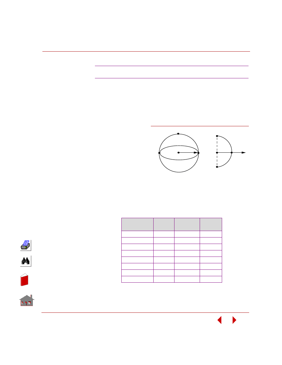
COSMOSM Basic FEA System
3-31
Part 2 Verification Problems
TYPE:
Frequency analysis using the nonaxisymmetric mode shape option (SHELLAX).
REFERENCE:
Krause, H., “Thin Elastic Shells,” John Wiley, Inc., New York, 1967.
PROBLEM:
Find the first eight
frequencies of the
spherical shell shown
here for the
circumferential
harmonic number 2.
GIVEN:
R
= 10 in
E
= 1E7 psi
ρ
= 0.0005208 lb-sec
2
/in
4
ν (NUXY) = 0.3
t (Thickness) = 0.1 in
COMPARISON OF RESULTS:
F26: Frequency Analysis of a Spherical Shell
Natural
Frequency No.
Theory
(Hz)
COSMOSM
(Hz)
Error (%)
1
1620
1622
0.12
2
1919
1923
0.20
3
2035
2044
0.44
4
2093
2110
0.81
5
2125
2153
1.32
6
2145
2188
2.00
7
2159
2224
3.01
8
2168
2262
4.34
Finite Element Model
X
4
3
2
1
Problem Sketch
44
4
R
Figure F26-1
In
de
x
In
de
x
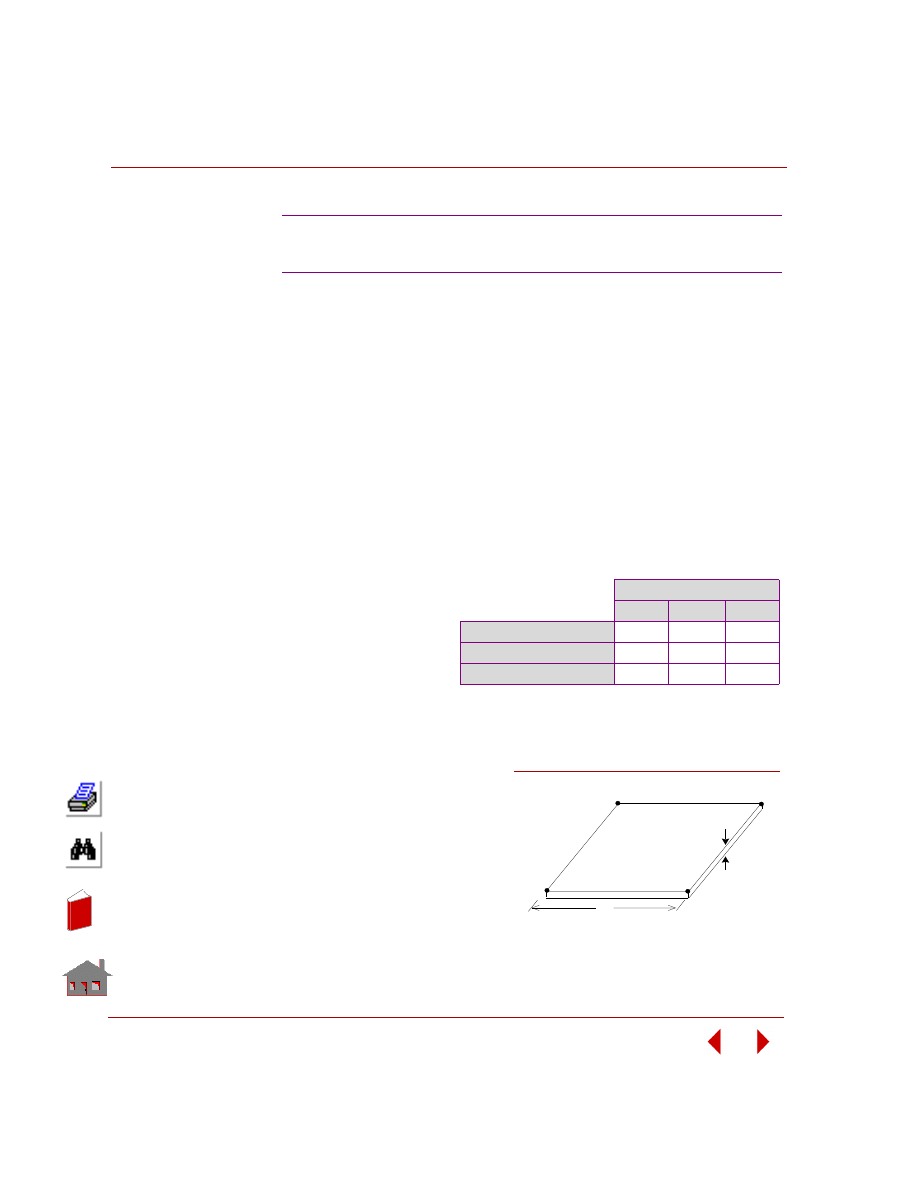
Chapter 3 Modal (Frequency) Analysis
3-32
COSMOSM Basic FEA System
TYPE:
Frequency analysis, Guyan reduction, SHELL4 elements.
Case A:
Guyan Reduction
Case B:
Consistent Mass
PROBLEM:
Natural frequencies of a simply-supported plate are calculated. Utilizing the
symmetry of the model, only one quarter of the plate is modeled and the first three
symmetric modes of vibration are calculated. The mass is lumped uniformly at
master degrees of freedom.
Theoretical results can be
obtained from the equation:
ω
mn
= r
2
D / L
2
U
∗
(m
2
+ n
2
)
Where:
D = Eh
3
/ 12(1 -
ν
2
)
U =
ρh
F27A, F27B: Natural Frequencies of a
Simply-Supported Square Plate
GIVEN:
L
= 30 in
h
= 0.1 in
ρ
= 8.29 x 10
-4
(lb sec
2
)/in
4
ν
= 0.3
E
= 30.E6 psi
ANALYTICAL
SOLUTION:
COMPARISON OF RESULTS:
Normalized mode shape displacements for the nodes
connected by the rigid bar.
Natural Frequency (Hz)
First
Second
Third
Theory
5.02
25.12
25.12
Case A: Guyan Reduction
5.03
25.15
25.20
Case B: Consistent Mass
5.02
25.11
25.11
Total Mass =
ρ
∗
ν
=
8.29
∗
10
-4
∗
0.1
∗
30
∗
30 =.07461
Lumped Mass at Master Nodes = .07461/64 = 1.16E-3
L
Problem Sketch
961
931
1
31
Simply
Supported
Plate
h
Figure F27-1
In
de
x
In
de
x
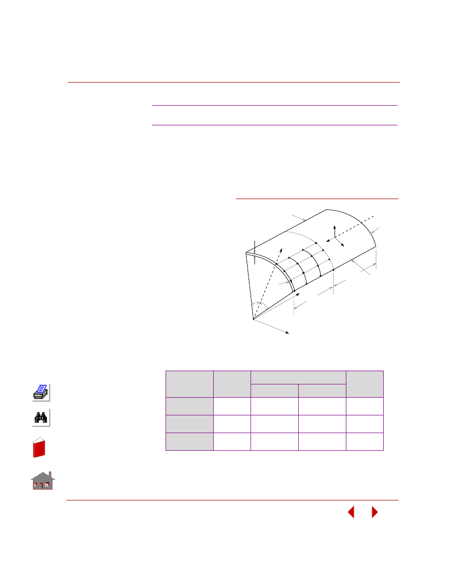
COSMOSM Basic FEA System
3-33
Part 2 Verification Problems
TYPE:
Natural mode shape and frequency, shell and rigid bar elements.
PROBLEM:
Determine the first frequency and mode shape of the shell roof shown below.
GIVEN:
r = 25 ft
E = 4.32E12,
4.32E11, and
4.32E10 psi
ν = 0
MODELING HINTS:
Due to symmetry, a
quarter of the shell roof
is considered in the
modeling. Nodes 8 and
12 are connected by a
rigid bar.
COMPARISON OF RESULTS:
Normalized mode shape displacements for the nodes connected by the rigid bar.
F28: Cylindrical Roof Shell
Method
Young's
Modulus
Z-Rotation
R8 / R12
Node 8 (R8)
Node 12 (R12)
Theory
COSMOSM
4.32E12
-0.5642901E-2
-0.5720E-2
-0.5642901E-2
-0.5720E-2
1.000
1.000
Theory
COSMOSM
4.32E11
-0.5654460E-2
-0.5720E-2
-0.5654460E-2
-0.5720E-2
1.000
1.000
Theory
COSMOSM
4.32E10
-0.5693621E-2
-0.5720E-2
-0.5693621E-2
-0.5720E-2
1.000
1.000
25 ft
25 ft
Free Edge
v =
w = 0
t = 0.25 ft
v = w = 0
40
°
40
°
Y
Z
U
V
W
1
4
13
16
X
Problem Sketch and Finite
Element Model
r
8
12
Free Edge
Figure F28-1
In
de
x
In
de
x
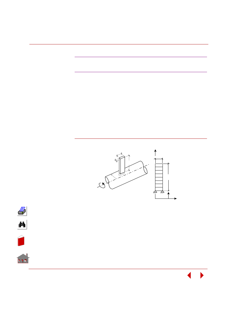
Chapter 3 Modal (Frequency) Analysis
3-34
COSMOSM Basic FEA System
TYPE:
Frequency analysis using the Spin Softening and Stress Stiffening Options.
REFERENCE:
W. Carnegie, “Vibrations of Rotating Cantilever Blade,” J. of Mechanical
Engineering Science, Vol. 1, No. 3, 1959.
PROBLEM:
Find the fundamental frequency of vibration of a blade cantilevered from a rigid
spinning rod.
Figure F29-1
MODELING HINTS:
The blade is cantilevered to a rigid rod. Therefore, the blade may be modeled with a
fixed displacement boundary condition at the connection to the rod. The Stress Stiff-
ening effect due to centrifugal load is considered in this model by activating the cen-
trifugal force option in
A_STATIC
command together with the Inplane Loading Flag
in
A_FREQUENCY
command.
F29A, B, C: Frequency Analysis
of a Spinning Blade
ω
b
t
h
R
Actual Model
Y
b
h
R
Finite Element Model
X
In
de
x
In
de
x
COSMOSM Basic FEA System
3-35
Part 2 Verification Problems
GIVEN:
R
= 150 mm
E = 217 x 10
9
Pa
h
= 328 mm
ρ = 7850 Kg/m
3
b
= 28 mm
γ = 0.3
t
= 3 mm
ω = 314.159 rad/sec
COMPARISON OF RESULTS:
Fundamental
Frequency (Hz)
Error (%)
Theory
52.75
A Stress stiffening with spin softening
51.17
3.0
B Stress stiffening with no spin softening
71.54
36.0
C No stress stiffening and no spin softening
23.80
54.9
In
de
x
In
de
x
3-36
COSMOSM Basic FEA System
In
de
x
In
de
x
COSMOSM Basic FEA System
4-1
4
Buckling Analysis
Introduction
This chapter contains verification problems to demonstrate the accuracy of the
Buckling Analysis module DSTAR.
List of Buckling Verification Problems
B1: Instability of Columns
B2: Instability of Columns
B3: Instability of Columns
B4: Simply Supported Rectangular Plate
B5A, B5B: Instability of a Ring
B6: Buckling Analysis of a Small Frame
B7A, B7B: Instability of Frames
B8: Instability of a Cylinder
B9: Simply Supported Stiffened Plate
B10: Stability of a Rectangular Frame
B11: Buckling of a Stepped Column
B12: Buckling Analysis of a Simply Supported Composite Plate
B13: Buckling of a Tapered Column
B14: Buckling of Clamped Cylindrical Shell Under External Pressure
Using the Nonaxisymmetric Buckling Mode Option
B15A, B15B: Buckling of Simply-Supported Cylindrical Shell Under Axial Load
In
de
x
In
de
x
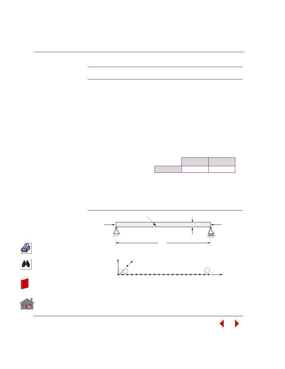
Chapter 4 Buckling Analysis
4-2
COSMOSM Basic FEA System
TYPE:
Buckling analysis, beam element (BEAM3D).
REFERENCE:
Brush, D. O., and Almroth, B. O., “Buckling of Bars, Plates, and Shells,” McGraw-
Hill, Inc., New York, 1975, p. 22.
PROBLEM:
Find the buckling load and deflection mode for a simply supported column.
ANALYTICAL SOLUTION:
P
cr
=
π
2
EI / L
2
= 9869.6 lb
Figure B1-1
B1: Instability of Columns
GIVEN:
E
= 30 x 10
6
psi
h
= 1 in
L
= 50 in
I
= 1/12 in
4
COMPARISON OF RESULTS:
Theory
COSMOSM
P
cr
9869.6 lb
9869.6 lb
Problem Sketch
P
P
L
EI
h
1 2 3
21
22
2
20
Y
Z
X
Finite Element Model
1
In
de
x
In
de
x
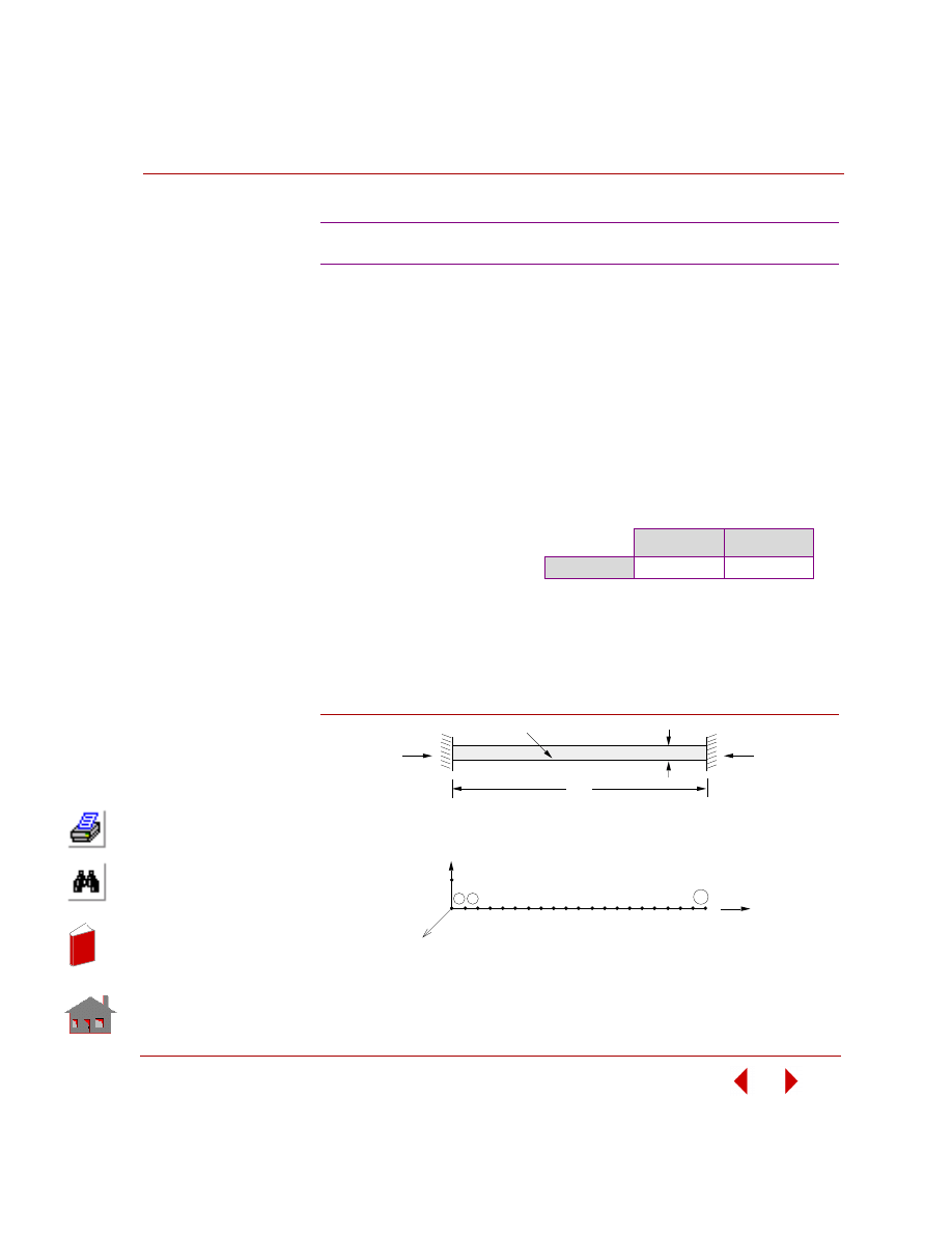
COSMOSM Basic FEA System
4-3
Part 2 Verification Problems
TYPE:
Buckling analysis, beam element (BEAM3D).
REFERENCE:
Brush, D. O., and Almroth, B. O., “Buckling of Bars, Plates, and Shells,” McGraw-
Hill, Inc., New York, 1975, p. 22.
PROBLEM:
Find the buckling load and deflection mode for a clamped-clamped column.
ANALYTICAL SOLUTION:
P
cr
= 4
π
2
EI / L
2
= 39478.4 lb
Figure B2-1
B2: Instability of Columns
GIVEN:
E
= 30 x 10
6
psi
h
= 1 in
L
= 50 in
I
= 1/12 in
4
COMPARISON OF RESULTS:
Theory
COSMOSM
P
cr
39478.4 lb
39478.8 lb
L
EI
h
1 2 3
21
22
1
2
20
Y
X
P
Problem Sketch
Finite Element Model
P
Z
In
de
x
In
de
x
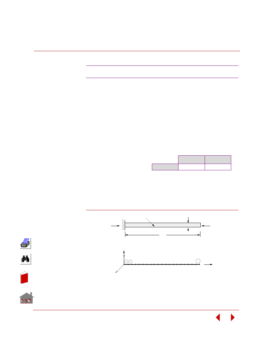
Chapter 4 Buckling Analysis
4-4
COSMOSM Basic FEA System
TYPE:
Buckling analysis, beam element (BEAM3D).
REFERENCE:
Brush, D. O., and Almroth, B. O., “Buckling of Bars, Plates, and Shells,” McGraw-
Hill, Inc., New York, 1975, p. 22.
PROBLEM:
Find the buckling load and deflection mode for a clamped-free column.
ANALYTICAL SOLUTION:
P
cr
=
π
2
EI / (4L
2
) = 2467.4 lb
Figure B3-1
B3: Instability of Columns
GIVEN:
E
= 30 x 10
6
psi
h
= 1 in
L
= 50 in
I
= 1/12 in
4
COMPARISON OF RESULTS:
Theory
COSMOSM
P
cr
2467.4 lb
2467.4 lb
Finite Element Model
1 2 3
21
22
1
2
20
Y
X
Z
Problem Sketch
L
EI
h
P
P
In
de
x
In
de
x
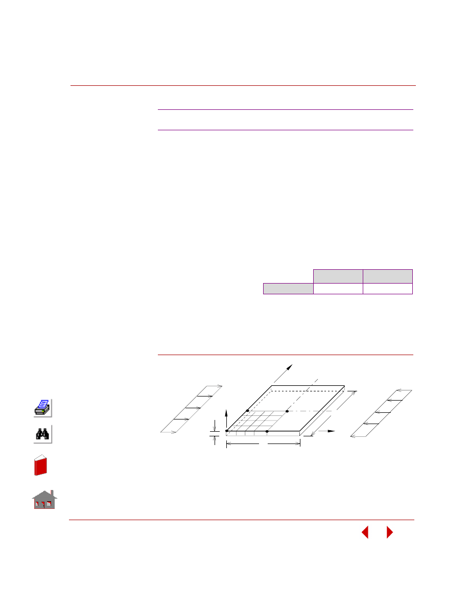
COSMOSM Basic FEA System
4-5
Part 2 Verification Problems
TYPE:
Buckling analysis, shell element (SHELL4).
REFERENCE:
Timoshenko, and Woinosky-Krieger, “Theory of Plates and Shells,” McGraw-Hill
Book Co., New York, 2nd Edition, p. 389.
PROBLEM:
Find the buckling load of a simply supported isotropic plate subjected to inplane
uniform load p applied at x = 0 and x = a.
Figure B4-1
B4: Simply Supported Rectangular Plate
GIVEN:
COMPARISON OF RESULTS:
E
= 30,000 psi
ν
= 0.3
h
= 1 in
a
= b = 40 in
p
= 1 lb/in
Theory
COSMOSM
P
cr
67.78 lb
67.85 lb
NOTE:
Due to double symmetry in geometry and loads,
a quarter of the plate is taken for modeling.
Z
Y
X
h
b
a
P
P
Problem Sketch and Finite Element Model
In
de
x
In
de
x
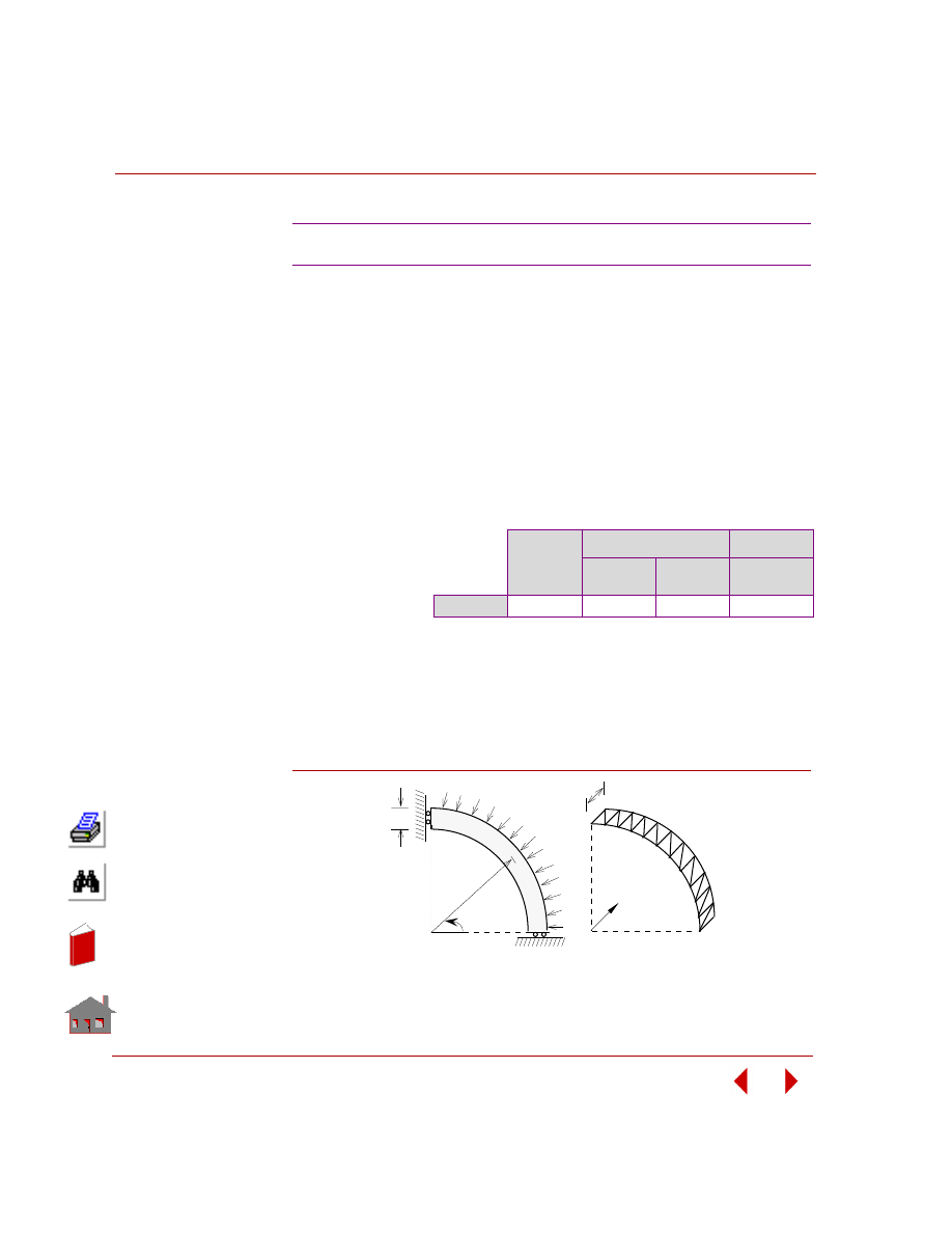
Chapter 4 Buckling Analysis
4-6
COSMOSM Basic FEA System
TYPE:
Buckling analysis, shell element (SHELL3, SHELL6).
REFERENCE:
Brush, D. O., and Almroth, B. O., “Buckling of Bars, Plates, and Shells,” McGraw-
Hill, Inc., New York, 1975, p. 139.
PROBLEM:
Find the buckling load and deflection mode of a ring under pressure loading.
ANALYTICAL SOLUTION:
Using Donnell Approximations.
P
cr
= 4EI / R
3
= 26.667 lb/in
Figure B5-1
B5A, B5B: Instability of a Ring
GIVEN:
E
= 10 x 10
6
psi
R
= 5 in
h
= 0.1 in
b
= 1 in
I
= 0.001/12 in
4
COMPARISON OF RESULTS:
Theory
COSMOSM
SHELL3
SHELL6
(Curved)
SHELL6
(Assembled)
Pcr
26.667 lb
26.674 lb
26.648 lb
-26.660 lb
Problem Sketch
Finite Element Model
z
b
h
R
θ
Pcr
In
de
x
In
de
x
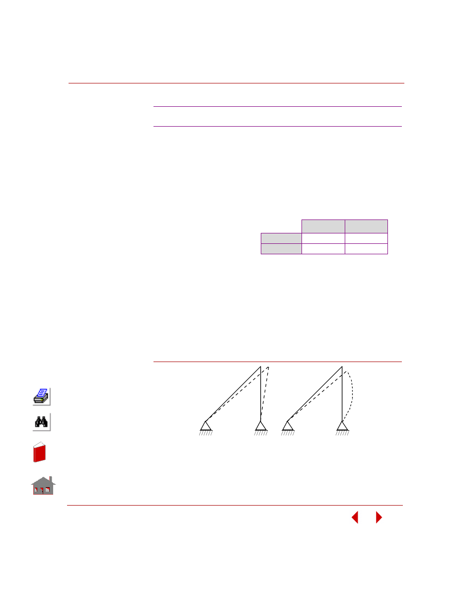
COSMOSM Basic FEA System
4-7
Part 2 Verification Problems
TYPE:
Buckling analysis, truss (TRUSS2D) and beam (BEAM3D) elements.
REFERENCE:
Timoshenko, S. P., and Gere, J. M., “Theory of Elastic Stability,” 2nd ed., McGraw-
Hill Book Co., New York, 1961, p. 45.
ANALYTICAL SOLUTION:
The classical results are obtained from:
P
1cr
= A
T
E Sin
α Cos
2
α / (1 + (A
T
/A
B
) Sin
3
α)
P
2cr
=
π
2
EI
B
/ L
2
MODE SHAPES:
Figure B6-1
B6: Buckling Analysis of a Small Frame
GIVEN:
L
= 20 in
A
B
= 4 in
2
A
T
= 0.1 in
2
E
= E
B
= E
T
= 30E6 psi
I
B
= 2 in
4
COMPARISON OF RESULTS:
Theory
COSMOSM
P
cr
1
1051.392 lb
1051.367 lb
P
cr
2
1480.44 lb
1481.20 lb
Mode Shape 1
Mode Shape 2
In
de
x
In
de
x
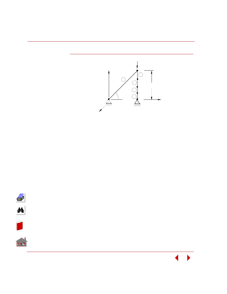
Chapter 4 Buckling Analysis
4-8
COSMOSM Basic FEA System
Figure B6-2
y
z
6
Truss
1
2
3
4
5
1
2
3
4
5
P
α
= 45
x
Problem Sketch and Finite Element Model
L
In
de
x
In
de
x
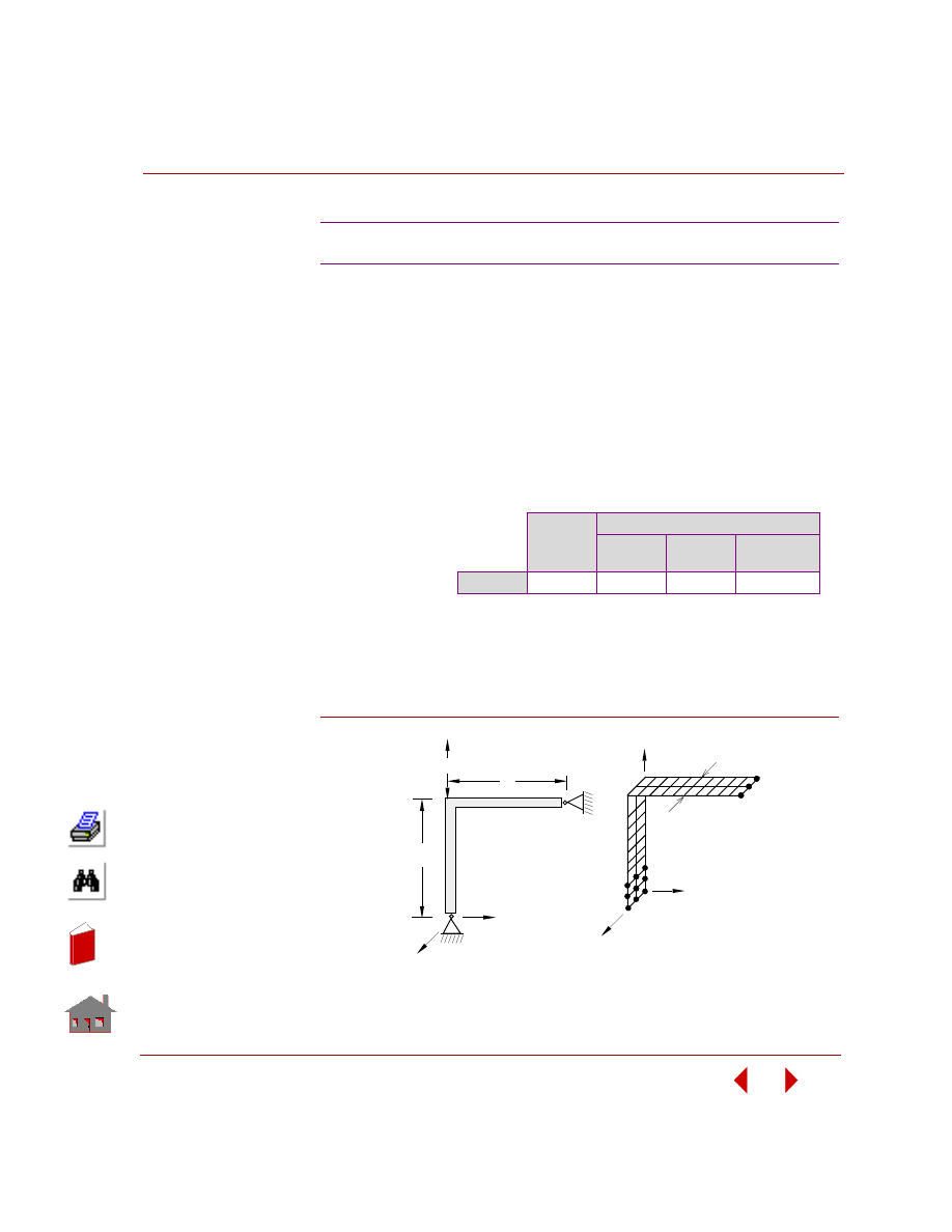
COSMOSM Basic FEA System
4-9
Part 2 Verification Problems
TYPE:
Buckling analysis, shell element (SHELL4 and SHELL6).
REFERENCE:
Brush, D. O., and Almroth, B. O., “Buckling of Bars, Plates, and Shells,” McGraw-
Hill, Inc., New York, 1975, p.29.
PROBLEM:
Find the buckling load and deflection mode for the frame shown below.
ANALYTICAL SOLUTION:
P
cr
= 1.406
π
2
EI / L
2
= 55506.6 lb
Figure B7-1
B7A, B7B: Instability of Frames
GIVEN:
E
= 30 x 10
6
psi
h
= 1 in
L
= 25 in
I
= 1/12 in
4
COMPARISON OF RESULTS:
Theory
COSMOSM
SHELL4
SHELL6
(Curved)
SHELL6
(Assembled)
P
cr
55506.6 lb 56280.8 lb 55364.9 lb
55732.1lb
Finite Element Model
h
Z
X
Y
Problem Sketch
L
L
P
Z
X
Y
In
de
x
In
de
x
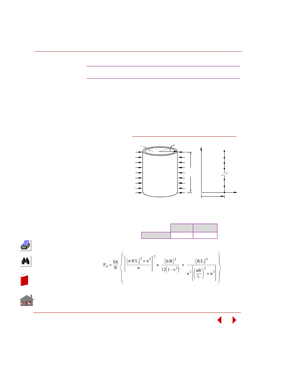
Chapter 4 Buckling Analysis
4-10
COSMOSM Basic FEA System
TYPE:
Buckling analysis, axisymmetric shell element (SHELLAX).
REFERENCE:
Brush, D. O., and Almroth, B. O., “Buckling of Bars, Plates, and Shells,” McGraw-
Hill, Inc., New York, 1975, p. 164.
PROBLEM:
Find the buckling
load and deflection
mode for a cylindrical
shell that is simply
supported at its ends
and subjected to uni-
form lateral pressure.
GIVEN:
E
= 10 x 10
6
psi
h
= 0.2 in
R
= 20 in
L
= 20 in
ν
= 0.3
ANALYTICAL SOLUTION:
B8: Instability of a Cylinder
COMPARISON OF RESULTS:
Theory
COSMOSM
P
cr
106 psi
113.97 psi
Finite Element Model
Y
X
R
Problem Sketch
h
R
L
Figure B8-1
In
de
x
In
de
x
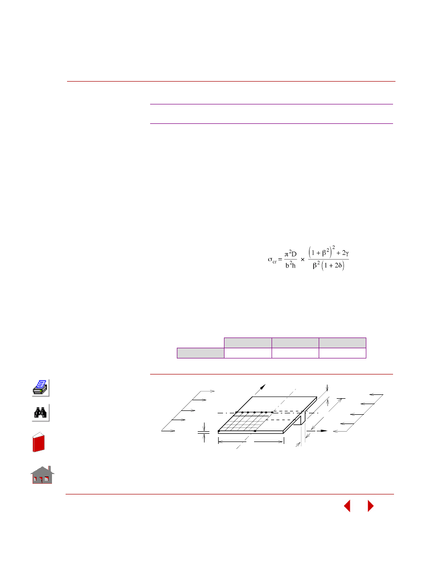
COSMOSM Basic FEA System
4-11
Part 2 Verification Problems
TYPE:
Buckling analysis, shell (SHELL4) and beam (BEAM3D) elements.
REFERENCE:
Timoshenko, S. P., and Gere, J. M., “Theory of Elastic Stability,” 2nd edition,
McGraw-Hill Book Co., Inc., New York, p. 394, Table 9-16.
PROBLEM:
A simply supported rectangular plate is stiffened by a beam of rectangular cross-
section as shown in the figure. The stiffened plate is subjected to inplane pressure at
edges x = 0 and x = a. Determine the buckling pressure load.
COMPARISON OF RESULTS:
Figure B9-1
B9: Simply Supported Stiffened Plate
GIVEN:
ANALYTICAL SOLUTION:
Where:
β = a/b γ = EI
b
/ bD D = E(h
p
)
3
/ 12(1-
ν
2
)
A
b
= b
b
x
h
b
δ = A
b
/ bh
p
E
= 30,000 kip/in
2
ν
= 0
h
p
= 1 in
a
= 45.5 in
b = 42 in
b
b
= 0.42 in
h
b
= 10 in
Theory
COSMOSM
Difference
P
cr
223.80 kip/in
232.53 kip/in
3.9%
Y
X
b
a
P
P
h
b
P
h
Problem Sketch and Finite Element Model
b
b
In
de
x
In
de
x
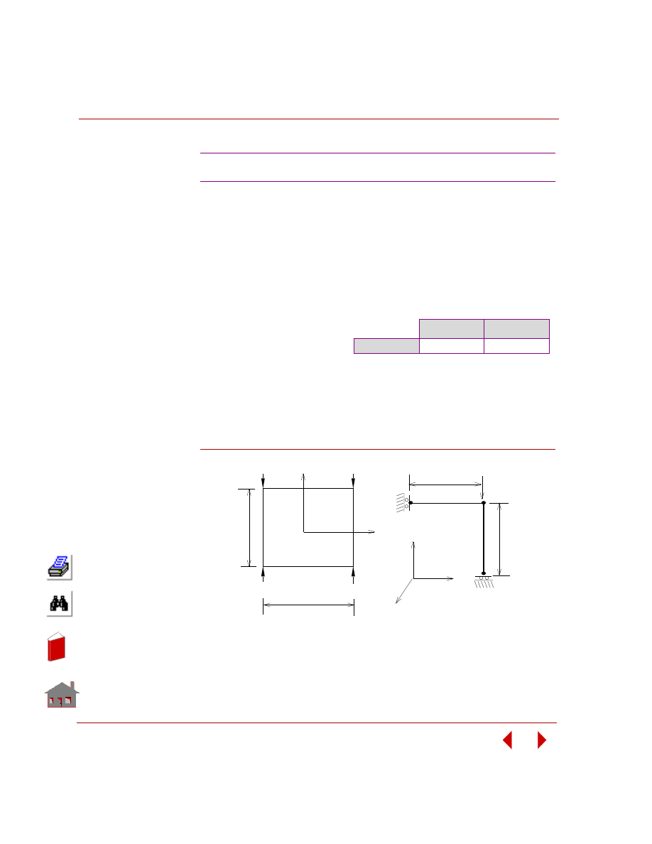
Chapter 4 Buckling Analysis
4-12
COSMOSM Basic FEA System
TYPE:
Buckling analysis, beam elements (BEAM2D).
REFERENCE:
Timoshenko, S. P. and Gere J. M., “Theory of Elastic Stability,” McGraw-Hill Book
Co., New York, 1961.
Figure B10-1
B10: Stability of a Rectangular Frame
GIVEN:
L
= b = l00 in
A
= 1 in
2
h
= 1 in (beam cross section
height)
I
= 0.0833 in
4
E
= 1 x 10
7
psi
P
= 100 lb
COMPARISON OF RESULTS:
Theory
COSMOSM
P
cr
1372.45 lb
1371.95 lb
ANALYTICAL SOLUTION:
P
cr
= 16.47EI/L
2
= 1372.4451 lb
Problem Sketch
P
P
P
P
L
Y
X
b
Finite Element Model
b/2
L/2
21
1
P
X
Y
Z
11
In
de
x
In
de
x
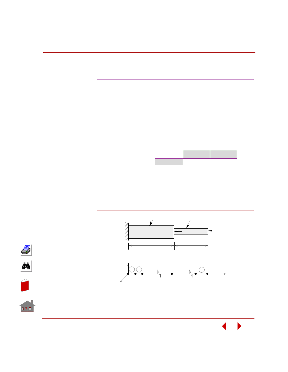
COSMOSM Basic FEA System
4-13
Part 2 Verification Problems
TYPE:
Buckling analysis, beam element (BEAM2D).
RFERENCE:
Roark, R. J. and Young, Y. C., “Formulas for Stress and Strain,” McGraw-Hill, New
York, l975, pp. 534.
PROBLEM:
Find the critical load and mode shape for the stepped column shown below.
Figure B11-1
B11: Buckling of a Stepped Column
GIVEN:
L
= 1000 mm
A
1
= 10,954 mm
2
A
2
= 15,492 mm
2
E
1
= E
2
= 68,950 MPa
ν
1
=
ν
2
= 0.3
I
1
= 1 x 10
7
mm
4
I
2
= 2 x 10
7
mm
4
P
1
/P
2
= 0.5
COMPARISON OF RESULTS:
Theory
COSMOSM
P
cr
554.6 KN
554.51 KN
ANALYTICAL SOLUTION:
P
cr
= 0.326
π
2
E
1
I
1
/ (2L)
2
= 554,600 N
= 554.6 KN
Finite Element Model
1
2
3
11
21
Y
20
20
X
Z
2
1
Problem Sketch
L
P
P
L
1
E , A , I
1
1
1
E , A , I
2
2
2
2
In
de
x
In
de
x
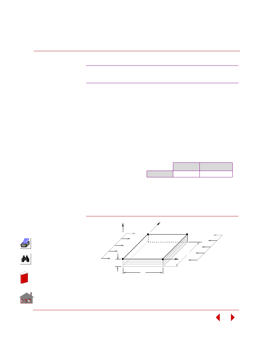
Chapter 4 Buckling Analysis
4-14
COSMOSM Basic FEA System
TYPE:
Buckling analysis, composite shell element (SHELL4L).
REFERENCE:
Jones, “Mechanics of Composite Material,” McGraw-Hill Book Co., New York, p.
269.
PROBLEM:
Find the buckling load for [45,-45,45,-45] antisymmetric angle-ply laminated plate
under uniform axial compression p.
Figure B12-1
B12: Buckling Analysis of a Simply
Supported Composite Plate
GIVEN:
a
= b = 40 in
h
=
Σh
i
= 1 in
E
x
= 400,000 psi
E
y
= 10,000 psi
ν
xy
= 0.25
G
xy
= G
yz
=G
xz
=5,000 psi
p
= 1 lb/in
2
COMPARISON OF RESULTS:
Theory
COSMOSM
P
cr
334.0 lb/in
345.36 lb/in
ANALYTICAL SOLUTION:
Approximate solution is given by graph
5-16 in the reference.
b
Problem Sketch and Finite Element Model
Z
Y
h
P
P
a
X
In
de
x
In
de
x
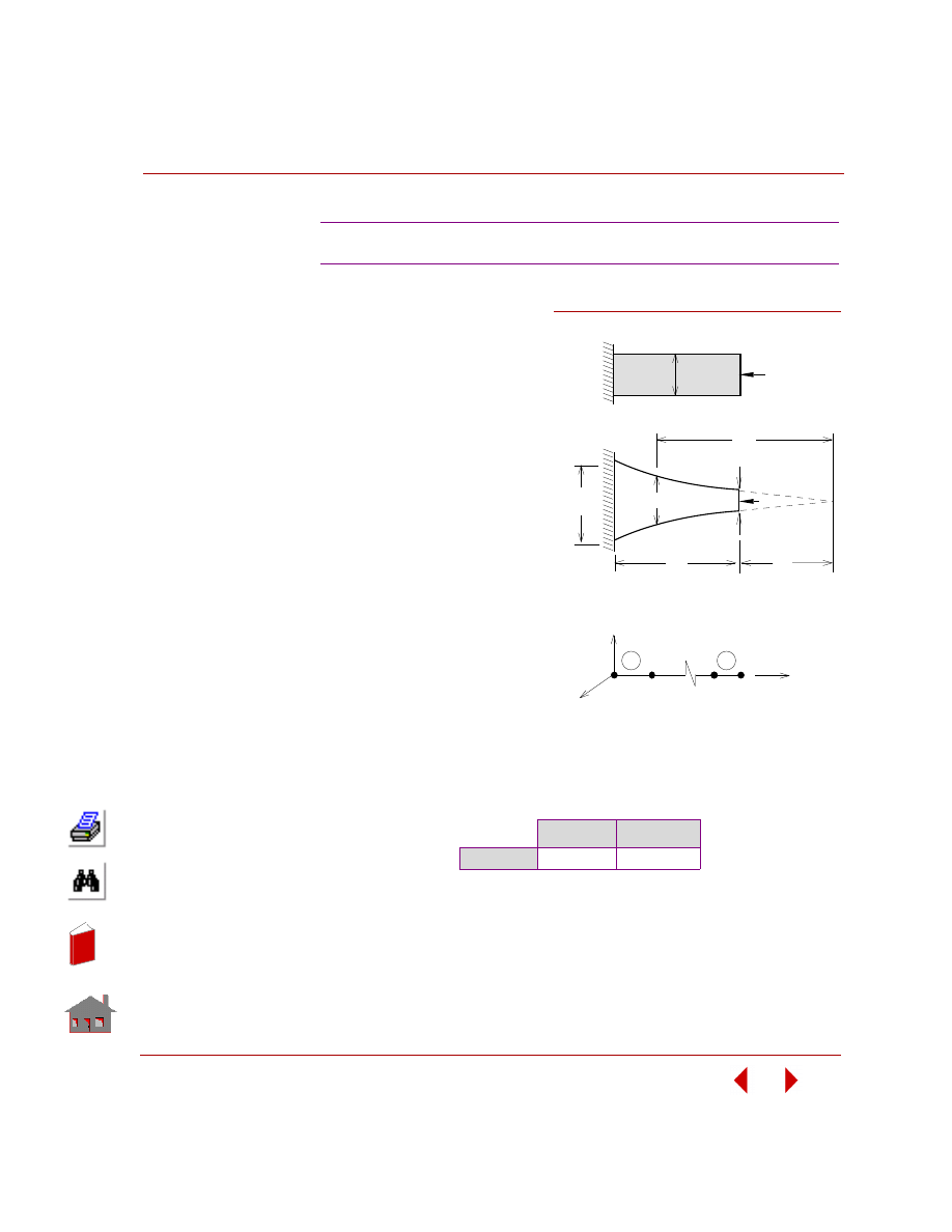
COSMOSM Basic FEA System
4-15
Part 2 Verification Problems
TYPE:
Buckling analysis, beam element (BEAM2D).
REFERENCE:
Timoshenko, S. P., and Gere, J. M., “Theory of Elastic Stability,” McGraw-Hill
Book Co., New York, 1961, pp. 125-128.
GIVEN:
b
1
= 1 in
b
2
= 4 in
b/b
1
= (x/a)
2
I
1
= 1 in
4
I
2
= 4 in
4
I
1
/I
2
= 0.25
L
= 100 in
a
= 100 in
E
= 1 x 10
7
psi
h
= 1 in
ANALYTICAL SOLUTION:
P
cr
= 1.678EI
2
/ L
2
= 6712 lb
COMPARISON OF RESULTS:
The Critical Load:
B13: Buckling of a Tapered Column
Theory
COSMOSM
P
cr
6712 lb
6718 lb
x
Finite Element Model
1
11
y
z
2
1
10
10
P
h
x
L
a
b1
P
b
2
Problem Sketch
SIDE VIEW
PLAN
b x
Figure B13-1
In
de
x
In
de
x
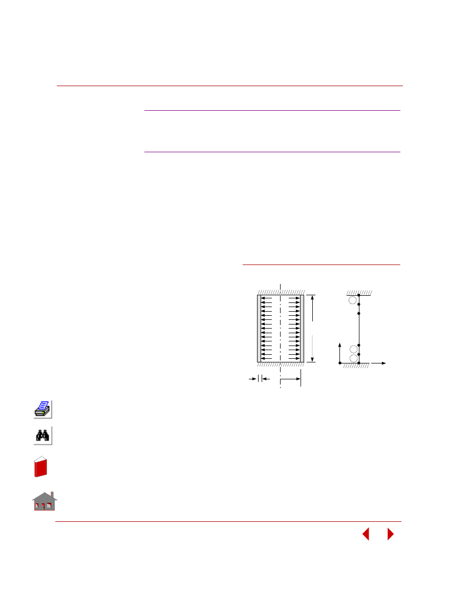
Chapter 4 Buckling Analysis
4-16
COSMOSM Basic FEA System
TYPE:
Linear buckling analysis using the nonaxisymmetric buckling mode option
(SHELLAX).
REFERENCE:
Sobel, L. H., “Effect of Boundary Conditions on the Stability of Cylinders Subject
to Lateral and Axial Pressures,” AIAA Journal, Vol. 2, No. 8, August, 1964, pp
1437-1440.
PROBLEM:
Find the buckling pressure for
the shown axisymmetric
clamped-clamped shell.
GIVEN:
R
= 1 in
ν
= 0.3
L
= 4 in
E
= 10
7
psi
t
= 0.01 in
MODELING HINTS:
The cylindrical shell is
modeled with 20 uniform
elements. The starting harmonic number for which the buckling load is calculated is
set to 2. The minimum buckling load occurs at harmonic number 5 which
corresponds to mode shape 4 since the program started from harmonic 2.
B14: Buckling of Clamped Cylindrical Shell
Under External Pressure Using the
Nonaxisymmetric Buckling Mode Option
Finite Element Model
1
2
3
20
19
21
x
y
2
1
20
R
t
L
CL
Problem Sketch
Figure B14-1
In
de
x
In
de
x
COSMOSM Basic FEA System
4-17
Part 2 Verification Problems
COMPARISON OF RESULTS:
Theory
COSMOSM
Harmonic Number
5
5
Critical Load
33.5 psi
35.0 psi
In
de
x
In
de
x
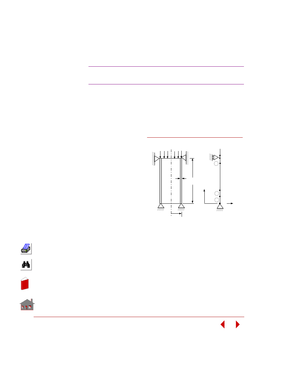
4-18
COSMOSM Basic FEA System
TYPE:
Linear buckling analysis using the nonaxisymmetric buckling mode option
(SHELLAX).
REFERENCE:
Timoshenko, S. P., and Gere, J. M., “Theory of Elastic Stability,” McGraw-Hill
Book Co., 1961.
PROBLEM:
Find the buckling load for
the simply-supported
cylindrical shell shown in
the figure below.
GIVEN:
R
= 10 in
L
= 16 in
ν (NUXY) = 0.3
E
= 10
7
psi
t
= 0.1 in
MODELING HINTS:
The cylindrical shell was modeled with 60 uniform elements. The starting harmonic
number for which the buckling load is calculated was set to 1. The solution stopped
at harmonic number 2 at which the minimum buckling load occurs. The number of
maximum iterations for the eigenvalue calculations was set to 100.
B15A, B15B: Buckling of Simply-Supported
Cylindrical Shell Under Axial Load
Finite Element Model
1
61
x
P
60
3
2
1
2
Y
60
Problem Sketch
L
R
t
CL
Figure B15A and B15B
In
de
x
In
de
x
COSMOSM Basic FEA System
4-19
Part 2 Verification Problems
COMPARISON OF RESULTS:
Harmonic
No.
Critical Load
B15A (SHELLAX) B15B (PLANE2D)
Theory
2
6.05 x 10
4
lb/rad
6.05 x 10
4
lb/rad
COSMOSM
2
6.07x 10
4
lb/rad
6.02x 10
4
lb/rad
In
de
x
In
de
x

Chapter 4 Buckling Analysis
4-20
COSMOSM Basic FEA System
In
de
x
In
de
x
COSMOSM Basic FEA System
I-1
Index
A
axisymmetric 2-7, 2-29, 2-30, 2-
axisymmetric shell 2-29, 2-60, 4-
B
beam 2-16, 2-18, 2-35, 2-36, 2-
38, 2-43, 2-45, 2-53, 2-54, 2-63,
2-65, 2-70, 2-80, 2-81, 2-83, 2-
85, 2-86, 2-111, 2-113, 3-5, 3-6,
3-14, 3-15, 4-7, 4-12
beam and truss 2-41
beam elements 2-14, 2-16, 2-18,
2-35, 2-36, 2-38, 2-43, 2-54, 2-
70, 2-80, 2-81, 2-83, 2-85
2-65, 2-71, 2-80, 2-81, 2-83, 2-
85, 2-111, 2-113, 4-12, 4-13, 4-15
2-41, 2-43, 2-45, 2-53, 2-54, 2-
63, 2-67, 2-70, 2-86, 3-5, 3-6, 3-
7, 3-14, 3-19, 4-2, 4-3, 4-4, 4-7,
4-11
BOUND 1-3
Buckling analysis 1-2, 4-1, 4-2,
4-3, 4-4, 4-5, 4-6, 4-7, 4-9, 4-10,
4-11, 4-12, 4-13, 4-14, 4-15, 4-
16, 4-18
C
centrifugal loading 2-62, 2-63
composite shell 2-33, 2-47
composite solid 2-56
constraint 2-68, 2-70, 2-71, 2-73
constraint elements 2-73
constraint equations 2-68
coupled degrees of freedom 2-
coupled points 2-68
CPCNS 2-70
cross-ply laminated 2-33
cyclic symmetry 2-99, 2-100
E
elastic foundation 2-128
ELBOW 1-3, 2-25, 2-26, 2-130
F
fluid sloshing 3-23, 3-25, 3-27
Frequency (modal) analysis 1-2
frequency analysis 3-21, 3-23, 3-
fundamental frequency 3-4, 3-5,
G
GAP 1-3
gap elements 2-111, 2-113, 2-114
GENSTIF 1-3
gravity loading 2-130
Guyan reduction 3-32
L
linear static analysis 1-2, 2-1, 2-
Linear static stress analysis 1-2
Linearized buckling analysis 1-2
M
MASS 1-3, 2-63, 3-3, 3-7
mass elements 2-63
Modal analysis 1-2
Mode shapes and frequencies 3-
3, 3-4, 3-5, 3-6, 3-7, 3-8, 3-9, 3-
10, 3-11, 3-12, 3-13, 3-14, 3-15,
3-16, 3-17, 3-19, 3-20, 3-21, 3-
22, 3-23, 3-25, 3-27, 3-29
N
natural frequencies 3-3, 3-6, 3-8,
3-9, 3-10, 3-11, 3-12, 3-13, 3-15,
3-17, 3-21, 3-23, 3-25, 3-32
In
de
x
In
de
x
Index
I-2
COSMOSM Basic FEA System
O
P
p-element 2-106, 2-117
Piezoelectric 3-29
piezoelectric 3-29
PIPE 1-3, 3-8
plane strain 2-12, 2-131, 2-133, 2-
plane strain solid 2-103
plane stress 2-13, 2-106, 2-117, 2-
PLANE2D 1-3, 2-7, 2-12, 2-13, 2-
28, 2-30, 2-62, 2-71, 2-75, 2-77,
2-79, 2-97, 2-98, 2-101, 2-103, 2-
105, 2-106, 2-108, 2-113, 2-123,
2-125, 2-129, 2-131, 2-132, 2-
133, 2-135, 2-141, 3-4, 3-22, 3-
23, 3-27
R
RBAR 1-3
rigid bar 3-32, 3-33
rigid body modes 3-14
S
sandwich beam 2-109
shell 2-29, 2-31, 2-39, 2-48, 2-50,
2-53, 2-66, 2-71, 2-89, 2-95, 4-10
shell element 2-29, 2-31, 2-50, 2-
67, 2-87, 2-89, 2-91, 2-95, 3-33
SHELL3 1-3, 2-9, 2-15, 2-48, 3-9,
SHELL3L 1-3
SHELL3T 1-3, 3-10, 3-17
SHELL4 1-3, 2-31, 2-39, 2-53, 2-
58, 2-66, 2-68, 2-121, 2-128, 3-9,
3-11, 3-12, 3-20, 3-32, 4-5, 4-9, 4-
11
SHELL4L 1-3, 2-33, 2-50, 2-67,
SHELL4T 1-4, 2-79, 3-17, 3-22
SHELL6 1-4, 2-13, 2-31, 2-66, 2-
SHELL9 1-4, 2-71, 2-87, 2-89, 2-
SHELL9L 1-4, 2-33, 2-47, 2-93
SHELLAX 1-4, 2-29, 2-60, 2-119,
2-120, 2-121, 3-21, 3-30, 3-31, 4-
10, 4-16, 4-18
SOLID 1-4, 2-19, 2-21, 2-47, 2-
56, 2-73, 2-77, 2-79, 2-115, 3-15,
3-22, 3-23, 3-25
SOLIDL 1-4, 2-47, 2-56, 2-93
SOLIDPZ 1-4, 3-29
SPRING 1-4
Static analysis 2-6, 2-7, 2-9, 2-13,
2-14, 2-15, 2-16, 2-18, 2-19, 2-22,
2-23, 2-24, 2-25, 2-26, 2-30, 2-31,
2-33, 2-39, 2-41, 2-43, 2-45, 2-47,
2-48, 2-50, 2-51, 2-53, 2-54, 2-56,
2-58, 2-60, 2-62, 2-63, 2-64, 2-65,
2-66, 2-67, 2-68, 2-70, 2-71, 2-73,
2-75, 2-77, 2-80, 2-81, 2-83, 2-85,
2-86, 2-87, 2-89, 2-91, 2-93, 2-95,
2-97, 2-98, 2-99, 2-100, 2-101, 2-
103, 2-105, 2-106, 2-107, 2-109,
2-110, 2-115, 2-127, 2-128, 2-
129, 2-131, 2-133, 2-135, 2-137,
2-139, 2-141
stepped column 4-13
stress intensity factor 2-97, 2-98,
stress stiffening 2-54, 3-34
submodeling 2-127
substructuring 2-51, 2-53, 2-58
support reactions 2-80, 2-81
T
TETRA10 1-4, 2-73, 3-22
TETRA4 1-4, 2-110
TETRA4R 1-4, 2-79, 2-91, 2-110,
thermal stress analysis 2-10, 2-12,
2-21, 2-28, 2-35, 2-36, 2-38, 2-
108
Thick Shell 2-48
thick shell 2-15
thin plate 2-9
thin shell 2-48
TRIANG 1-4, 2-79, 2-100, 2-106,
2-107, 2-117, 2-127, 2-131, 2-
132, 2-133, 2-135, 3-22
truss 2-6, 2-10, 2-22, 2-23, 2-24,
2-35, 2-51, 2-53, 2-64, 3-3, 3-16
TRUSS2D 1-4, 2-10, 2-51, 2-64,
TRUSS3D 1-4, 2-6, 2-22, 2-23, 2-
In
de
x
In
de
x
Document Outline
- COSMOSM Basic System (Part 2)
- 1 About the Verification Problems...
- 2 Linear Static Analysis
- Introduction
- S1: Pin Jointed Truss
- S2: Long Thick-Walled Cylinder
- S3A, S3B: Simply Supported Rectangular Plate
- S4: Thermal Stress Analysis of a Truss Structure
- S5: Thermal Stress Analysis of a 2D Structure
- S6A, S6B: Deflection of a Cantilever Beam
- S7: Beam Stresses and Deflections
- S8: Tip Displacements of a Circular Beam
- S9A: Clamped Beam Subject to Imposed Displacement
- S9B: Clamped Beam Subject to Imposed Rotation
- S10A, S10B: Bending of a Solid Beam
- S11: Thermal Stress Analysis of a 3D Structure
- S12: Deflection of a Hinged Support
- S13: Statically Indeterminate Reaction Force Analysis
- S14A, S14B: Space Truss with Vertical Load
- S15: Out-of-Plane Bending of a Curved Bar
- S16A, S16B: Curved Pipe Deflection
- S17: Rectangular Plate Under Triangular Thermal Loading
- S18: Hemispherical Dome Under Unit Moment Around Free Edge
- S19: Hollow Thick-walled Cylinder Subject to Temperature and Pressure
- S20A, S20B: Cylindrical Shell Roof
- S21A, S21B: Antisymmetric Cross-Ply Laminated Plate (SHELL4L)
- S22: Thermally Loaded Support Structure
- S23: Thermal Stress Analysis of a Frame
- S24: Thermal Stress Analysis of a Simple Frame
- S25: Torsion of a Square Box Beam
- S26: Beam With Elastic Supports and a Hinge
- S27: Frame Analysis with Combined Loads
- S28: Cantilever Unsymmetric Beam
- S29A, S29B: Square Angle-Ply Composite Plate Under Sinusoidal Loading
- S30: Effect of Transverse Shear on Maximum Deflection
- S31: Square Angle-Ply Composite Plate Under Sinusoidal Loading
- S32A, S32B, S32C, S32D, S32M: Substructure of a Tower
- S33A, S33M: Substructure of an Airplane (Wing)
- S34: Tie Rod with Lateral Loading
- S35A, S35B: Spherical Cap Under Uniform Pressure (Solid)
- S36A, S36M: Substructure of a Simply Supported Plate
- S37: Hyperboloidal Shell Under Uniform Ring Load Around Free Edge
- S38: Rotating Solid Disk
- S39: Unbalanced Rotating Flywheel
- S40: Truss Structure Subject to a Concentrated Load
- S41: Reactions of a Frame Structure
- S42A, S42B: Reactions and Deflections of a Cantilever Beam
- S43: Bending of a T Section Beam
- S44A, S44B: Bending of a Circular Plate with a Center Hole
- S45: Eccentric Frame
- S46, S46A, S46B: Bending of a Cantilever Beam
- S47, S47A, S47B: Bending of a Cantilever Beam
- S48: Rotation of a Tank of Fluid (PLANE2D Fluid)
- S49A, S49B: Acceleration of a Tank of Fluid (PLANE2D Fluid)
- S50A, S50B, S50C, S50D, S50F, S50G, S50H, S50I: Deflection of a Curved Beam
- S51: Gable Frame with Hinged Supports
- S52: Support Reactions for a Beam with Intermediate Forces and Moments
- S53: Beam Analysis with Intermediate Loads
- S54: Analysis of a Plane Frame with Beam Loads
- S55: Laterally Loaded Tapered Beam
- S56: Circular Plate Under a Concentrated Load (SHELL9 Element)
- S57: Test of a Pinched Cylinder with Diaphragm (SHELL9 Element)
- S58A, S58B, S58C: Deflection of a Twisted Beam with Tip Force
- S59A, S59B, S59C: Sandwich Square Plate Under Uniform Loading (SHELL9L)
- S60: Clamped Square Plate Under Uniform Loading
- S61: Single-Edge Cracked Bend Specimen, Evaluation of Stress Intensity Factor Using Crack Element
- S62: Plate with Central Crack
- S63: Cyclic Symmetry Analysis of a Hexagonal Frame
- S64A, S64B: Cyclic Symmetry
- S65: Fluid-Structure Interaction, Rotation of a Tank of Fluid
- S66: Fluid-Structure Interaction, Acceleration of a Tank of Fluid
- S67: MacNeal-Harder Test
- S68: P-Method Solution of a Square Plate with Hole
- S69: P-Method Analysis of an Elliptic Membrane Under Pressure
- S70: Thermal Analysis with Temperature Dependent Material
- S71: Sandwich Beam with Concentrated Load
- S74: Constant Stress Patch Test (TETRA4R)
- S75: Analysis of a Cantilever Beam with Gaps, Subject to Different Loading Conditions
- S76: Simply Supported Beam Subject to Pressure from a Rigid Parabolic Shaped Piston
- S77: Bending of a Solid Beam Using Direct Material Matrix Input
- S78: P-Adaptive Analysis of a Square Plate with a Circular Hole
- S79: Hemispherical Shell Under Unit Moment Around Free Edge
- S80: Axisymmetric Hyperbolic Shell Under a Cosine Harmonic Loading on the Free Edge
- S81: Circular Plate Under Non-Axisymmetric Load
- S82: Twisting of a Long Solid Shaft
- S83: Bending of a Long Solid Shaft
- S84: Submodeling of a Plate
- S85: Plate on Elastic Foundation
- S86: Plate with Coupled Degrees of Freedom
- S87: Gravity Loading of ELBOW Element
- S88A, S88B: Single-Edge Cracked Bend Specimen, Evaluation of Stress Intensity Factor Using the J-...
- S89A, S89B: Slant-Edge Cracked Plate, Evaluation of Stress Intensity Factors Using the J-integral
- S90A, S90B: Penny-Shaped Crack in Round Bar, Evaluation of Stress Intensity Factor Using the J-in...
- S91: Crack Under Thermal Stresses, Evaluation of Stress Intensity Using the J-integral
- S92A, S92B: Simply Supported Rectangular Plate, Using Direct Material Matrix Input
- S93: Accelerating Rocket
- S94A, S94B, S94C: P-Method Solution of a Square Plate with a Small Hole
- S95A, S95B, S95C: P-Method Solution of a U- Shaped Circumferential Groove in a Circular Shaft
- Introduction
- 3 Modal (Frequency) Analysis
- Introduction
- F1: Natural Frequencies of a Two-Mass Spring System
- F2: Frequencies of a Cantilever Beam
- F3: Frequency of a Simply Supported Beam
- F4: Natural Frequencies of a Cantilever Beam
- F5: Frequency of a Cantilever Beam with Lumped Mass
- F6: Dynamic Analysis of a 3D Structure
- F7A, F7B: Dynamic Analysis of a Simply Supported Plate
- F8: Clamped Circular Plate
- F9: Frequencies of a Cylindrical Shell
- F10: Symmetric Modes and Natural Frequencies of a Ring
- F11A, F11B: Eigenvalues of a Triangular Wing
- F12: Vibration of an Unsupported Beam
- F13: Frequencies of a Solid Cantilever Beam
- F14: Natural Frequency of Fluid
- F16A, F16B: Vibration of a Clamped Wedge
- F17: Lateral Vibration of an Axially Loaded Bar
- F18: Simply Supported Rectangular Plate
- F19: Lowest Frequencies of Clamped Cylindrical Shell for Harmonic No. = 6
- F20A, F20B, F20C, F20D, F20E, F20F, F20G, F20H: Dynamic Analysis of Cantilever Beam
- F21: Frequency Analysis of a Right Circular Canal of Fluid with Variable Depth
- F22: Frequency Analysis of a Rectangular Tank of Fluid with Variable Depth
- F23: Natural Frequency of Fluid in a Manometer
- F24: Modal Analysis of a Piezoelectric Cantilever
- F25: Frequency Analysis of a Stretched Circular Membrane
- F26: Frequency Analysis of a Spherical Shell
- F27A, F27B: Natural Frequencies of a Simply-Supported Square Plate
- F28: Cylindrical Roof Shell
- F29A, B, C: Frequency Analysis of a Spinning Blade
- Introduction
- 4 Buckling Analysis
- Introduction
- B1: Instability of Columns
- B2: Instability of Columns
- B3: Instability of Columns
- B4: Simply Supported Rectangular Plate
- B5A, B5B: Instability of a Ring
- B6: Buckling Analysis of a Small Frame
- B7A, B7B: Instability of Frames
- B8: Instability of a Cylinder
- B9: Simply Supported Stiffened Plate
- B10: Stability of a Rectangular Frame
- B11: Buckling of a Stepped Column
- B12: Buckling Analysis of a Simply Supported Composite Plate
- B13: Buckling of a Tapered Column
- B14: Buckling of Clamped Cylindrical Shell Under External Pressure Using the Nonaxisymmetric Buck...
- B15A, B15B: Buckling of Simply-Supported Cylindrical Shell Under Axial Load
- Introduction
- Index
Wyszukiwarka
Podobne podstrony:
2009 11 17 arduino basics
LV Basics I (2)
Excel VBA Course Notes 1 Macro Basics
CATIA V5 Training Basics
AT2H Basics Hindu Culture Part 2
AT2H Basics Education in Ancient India
Basics I
Basics of Assembler
Basics Of Hacking 2 VAXs
Front End Alignment Basics
Software basics
BASICS
Blot Basics
Basics
Direct3D 9 Basics
Lean Manufacturing Basics Aza Badurdeen [ENG]
Edgecam Manufacturing Basics1
N P Todkar Piping Drawings Basics
AT2H Basics Hindu Music
więcej podobnych podstron