1
Fan Engineering FE-3700
©2006 Twin City Fan Companies, Ltd.
Introduction
Traditionally, fan manufacturers have tested several sizes
of fans out of a product line and used the fan laws to
generate ratings for the complete line. The same air and
sound performance ratings were used for all arrangements
and classes of construction that were offered within the
line. It has always been recognized that these product
variations would affect the performance. However, as long
as the actual performance was within the stated toleranc-
es, the effects of construction variations were ignored.
Several factors have combined in recent years to promote
the need for change:
1. The need to improve building efficiency as promoted
in the LEEDS program and ASHRAE 90.1 has lead to
stronger awareness of “as installed” fan efficiency.
2. Fan customers have been pushed to make tighter and
tighter guarantees on their equipment, thus increasing
the need for tighter accuracy on the fan ratings.
3. The AMCA certified ratings program for fan air perfor-
mance now allows the manufacturer to certify fan effi-
ciency. Compliance with the efficiency tolerances will
require more precise ratings than current methods.
4. A recent article in the November 2005 issue of the
ASHRAE Journal suggests that fan manufacturers should
be testing more samples to establish their ratings.
5. The accuracy of sound power ratings is becoming
increasingly important.
Improvements in Adjusting for Fan
Arrangements
A fan commonly used in air handling units is the airfoil
bladed plenum fan. Its efficiency, combined with compact
size and versatility in duct take-offs, have made it ideal
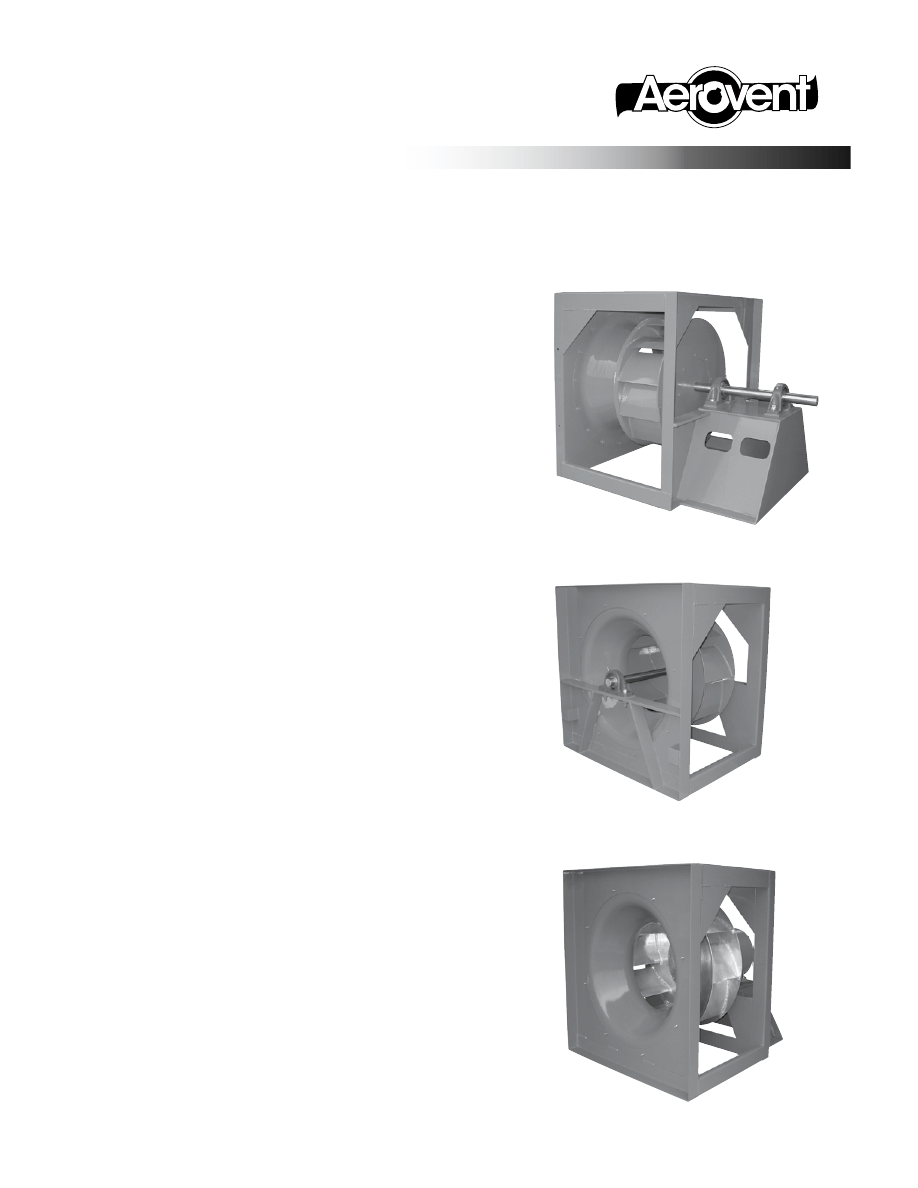
for many applications. There are three common arrange-
ments that manufacturers may offer:
Arrangement 1: This has a pedestal that supports two
bearings. The fan impeller is over-hung
on one side and the fan sheave is
mounted on the opposite end.
Arrangement 3: This arrangement has one bearing
mounted in the inlet side and the
other bearing on the backside of the
fan impeller. The impeller is thus cen-
ter-hung. The fan sheave is normally
mounted on the shaft extension, which
protrudes through the rear bearing.
Arrangement 4: The fan impeller is mounted directly on
the motor shaft. There is no fan shaft
or fan bearings.
Improvements in Fan Performance
Rating Methods for Air and Sound
Arrg. 4
Plenum Fan
Arrg. 3
Plenum Fan
Arrg. 1
Plenum Fan
Information and Recommendations for the Engineer
®
FE-3700
F
AN
E
NGINEERING
2
Fan Engineering FE-3700
ers do not do this. A blade reinforcement ring can also
degrade fan performance substantially, but this may not
be reflected in the performance ratings of some manu-
facturers.
The Impact of Fan Accessories
Just as the accessories installed on a car can affect gas
mileage, fan accessories can affect fan efficiency and
sound. Some common fan accessories are as follows:
1. Inlet screens: These will affect performance and their
loss is normally not accounted for in the ratings.
Some air handling manufacturers avoid inlet screens
by use of electrical interlocks in the doors. These
require the fan power to be cut prior to accessing
the unit interior.
2. Protective Enclosures: These enclose the fan impeller
and have a high percentage of open area to reduce
losses. A good design will have minimal effect on
performance and its effect can be ignored. Welded
heavy wire performs best, but non-flattened expanded
metal also has minimal losses
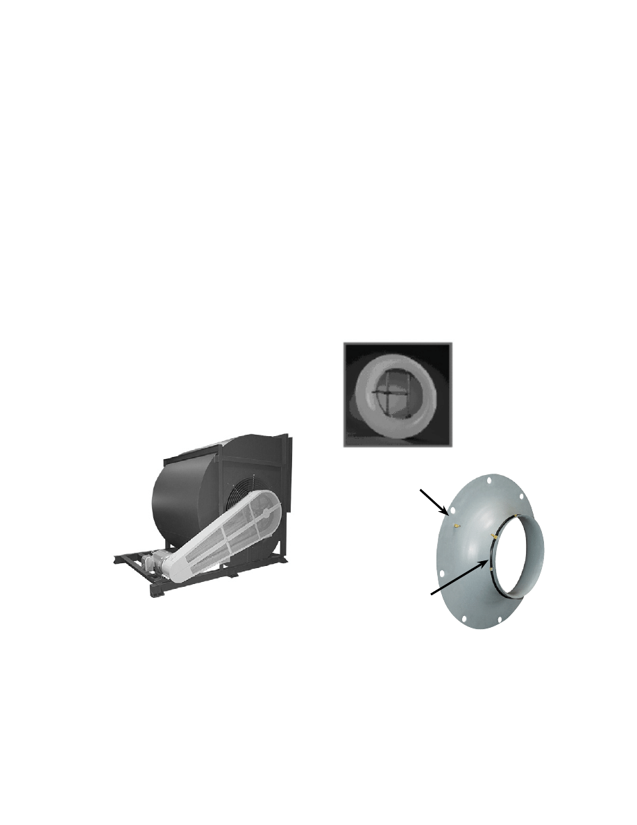
3. Flow Measurement Tubes and Probes: When mount-
ed in the throat of the inlet cone, these can have
dramatic losses. Do not use for optimum efficiency.
Consider the use of the piezometer style flow mea-
surement, which has no loss.
4. V-belt Drives: Plenum fan and airfoil double width
fans do not include V-belt drive losses. Do not over-
specify V-belt drives. Service factors from 1.3 to 1.5
will always provide good life on these types of fan.
Specifying “two-groove minimum” on fans five horse-
power and smaller can be counter-productive to reli-
ability and can waste a large percentage of the power.
AMCA 203: “Field Performance Measurement of Fan
Systems” shows a table for estimating V-belt drive
losses that works well for normal service factors.
The Arrangement 4 has no obstruction in the inlet, and no
bearing drag loss to incorporate and therefore will have
the best efficiency. A close second is the Arrangement 1
fan, which also has the open inlet, but includes the bear-
ing drag losses. The lowest efficiency is the Arrangement
3 fan, which typically has a pillow block bearing as well
as its support structure directly in the high velocity inlet
air. This causes increased aerodynamic losses. It also has
the bearing drag loss.
It was common for fans that were offered both in
Arrangements 1 and 3 to use the Arrangement 1 for rat-
ing purposes. It gave higher efficiencies than Arrangement
3, and if all manufacturers used the same methods, the
results were comparable. However, the Arrangement 3
fan could actually be 5-10 percent lower in efficiency.
This difference has become important when considering
the developments discussed above. Manufacturers can
and are responding to the current situation by having
separate AMCA certified ratings for the fans that have
the bearings in the inlet (Arrg. 3) versus those that do
not (Arrg. 1 and 4). While this increases the time and
expense required to get new products to the market, it
provides more accurate ratings required by air handling
equipment manufacturers who utilize the Arrangement 3
fans. It should be noted that Arrangement 3 has a cost
advantage in that it has a smaller footprint along the
axial direction.
Another common fan used in air handlers are airfoil,
double width fans that use scroll type housings. Since
these are only offered in the Arrangement 3 configuration,
the performance ratings of different manufacturers should
be comparable. The only change anticipated on this fan
line to improve rating accuracy is to test more sizes. This
is to allow for the fact that there are some “size effects”
that the fan laws do not predict.
Considerations of Fan Class of
Construction
The fan class determines the maximum allowable operat-
ing speed of the fan. In the higher classes, the materials
of construction may be changed to stronger, thicker or
more heavily reinforced construction. In very high speed
construction, fan manufacturers can use higher cost, high
strength steels or they may choose to add blade rein-
forcing rings. These may be segmented gussets that are
welded to the blades near the mid-span of the blade, or
they could be a continuous ring.
While it is possible to make airfoil fans to generate high
pressure without reinforcement rings, some manufactur-
Piezometer Ring
Mounted at Throat
of Inlet Cone
Inlet Tap
Mounted on
Face of Inlet
Cone
Arrg. 3
DWDI Fan
Flow tubes in inlet (left)
create large losses,
whereas a piezometer ring
(below) has no loss.

3
Fan Engineering FE-3700
5. Inlet Vanes: The purpose of the inlet vane is to
change the performance in a controlled manner.
However, there are also losses with the vane fully
open that the fan manufacturer can correct for in their
published performance. The popularity of inlet vanes
has declined due to the wide acceptance of inverter
driven motors.
6. Inverter driven motors (VFD): Fan users should be
aware that VFDs induce two types of power losses
that are often overlooked due to sparse data from the
manufacturers. The inverter itself has electrical losses
that result in heating of the inverter. Also, since the
output of the inverter is not sinusoidal, there is a loss
of motor efficiency. Some motor manufacturers state
that a motor with a 1.15 service factor will have a
1.0 service factor when inverter driven. At the time
of this writing, there is no motor industry standard to
allow motor manufacturers to publish these losses in
a uniform manner.
7. Most other accessories will not affect performance
to a significant degree. Up-sized bearings will have
slightly higher bearing drag. Belt guards on plenum
fans have minimal effects if driven from the “back”
(opposite inlet) side.
Recommendations for Fan Users
1. Where an Arrangement 3 fan is being used, specify
that the fan air, inlet and outlet sound ratings must
be AMCA certified from Arrangement 3 tests. Some
manufacturers may provide derate factors, but these
are not likely certified and are of questionable accu-
racy.
2. When comparing ratings between manufacturers, make
sure that all fans are of like construction. Comparing
an Arrangement 3 performance from one manufacturer
to an Arrangement 1 of another will lead to the wrong
conclusions.
3. Specify that no blade rings should be used or make
inquiries to the manufacturer on their use of blade
reinforcing rings, and whether the ratings are adjusted
for the rings.
4. Some air handling manufacturers use a variety of fan
arrangements in their designs. A fan manufacturer
that can provide accurate AMCA certified ratings in
all arrangements will simplify fan selection and assure
design and data integrity.
5. Consider the impact of accessories on fan perfor-
mance and avoid those that cause significant losses.
Additional Observations and
Conclusions
Fan users' requests for better precision in fan ratings are
forcing responsible fan manufacturers to perform a great
deal more testing. A primary impetus of this is to know
more accurately the fan efficiency for all variations of fan
design. A side benefit of this is that all fan samples are
also tested for sound. It has been found that the bear-
ing mounted in the inlet also affects the sound ratings
and these should be rated separately. Unless the fans
are perfectly symmetrical, inlet sound power and outlet
sound power are not equal. Therefore, these should be
rated separately.
Intelligent comparisons of fan ratings involve “digging
into” the details. Users should know the configuration of
the fans used for ratings and whether any blade reinforce-
ment is used that is not accounted for in the ratings.
Finally, be aware that the use of fan accessories can
affect performance. Accessory effects can be minimized
by effective design.
Although it is possible to certify fans for efficiency, at
the time of this writing, no manufacturers had done so.
If this has value to fan users, they should work with the
manufacturers to encourage them to adapt this added
assurance of accurate ratings.

AERovENt | www.AERovENt.com
5959 trenton Lane N | minneapolis, mN 55442 | Phone: 763-551-7500 | Fax: 763-551-7501
®
Wyszukiwarka
Podobne podstrony:
Improvements in Fan Performance Rating Methods for Air and Sound
Numerical Methods for Engineers and Scientists, 2nd Edition
Sobczyński, Marek Borderlands in Africa as an asylum for war and political refugees (2003)
Miller Recent Developments In Slab A Software Based System For Interactive Spatial Sound Synthesis
Canadian Patent 33,317 Improvements in Methods and Apparatus for Converting Alternating into Direct
Canadian Patent 30,172 Improvements in Methods of and Apparatus for Converting and Distributing Elec
British Patent 2,812 Improvements in Methods of and Apparatus for the Generation of Electric Current
Canadian Patent 29,537 Improvements in Methods of and Apparatus for the Electrical Transmission of P
Performance Improvements in an arc welding power supply based on resonant inverters (1)
Method Development in High Performance Liquid Chromatography
British Patent 2,801 Improvements in Reciprocating Engines and Means for Regulating the Period of th
Semi Empirical Method for Estimating the Combustion Wave Transition through the Contact Surface in a
Method for enhancing solubility of the expressed recombinant protein in E coli
Bearden Tech papers Bedini s Method for Forming Negative Resistors in Batteries (www cheniere org)
British Patent 8,575 Improved Methods of and Apparatus for Generating and Utilizing Electric Energy
Review of methods for demonstrating redundancy in DP systems for the offshore industry
Free Energy Bedini Device And Method For Pulse Charging A Battery Patent Info 2004
Finished drawing for air reservoir,pressure tank,calorifer
więcej podobnych podstron