
L8542447
05/2008 rev 2 ENG
CALL
UNIONE NAZIONALE COSTRUTTORI
AUTOMATISMI PER CANCELLI, PORTE
SERRANDE ED AFFINI
F2
F2
F2 115V 0,2AT
F2 230V 0,1AT
F2 24V 0,5AT
N
CH1
PG
CH2
CH3
CH4
L
ANT
SHIELD
ANT
BATT 12Vdc
+
-
U2
RADIO
J4
CH4 N.O.
CH4 N.C.
J3
CH3 N.O.
CH3 N.C.
J2
CH2 N.O.
CH2 N.C.
J1
CH1 N.O.
CH1 N.C.
ADV
N.C.
1
2
3
4
5
6
7
8
9
10
11
12
13
14
F1
T315mA
SIM CARD
DL2 DL3 DL4 DL1
S1
ALARM

CALL
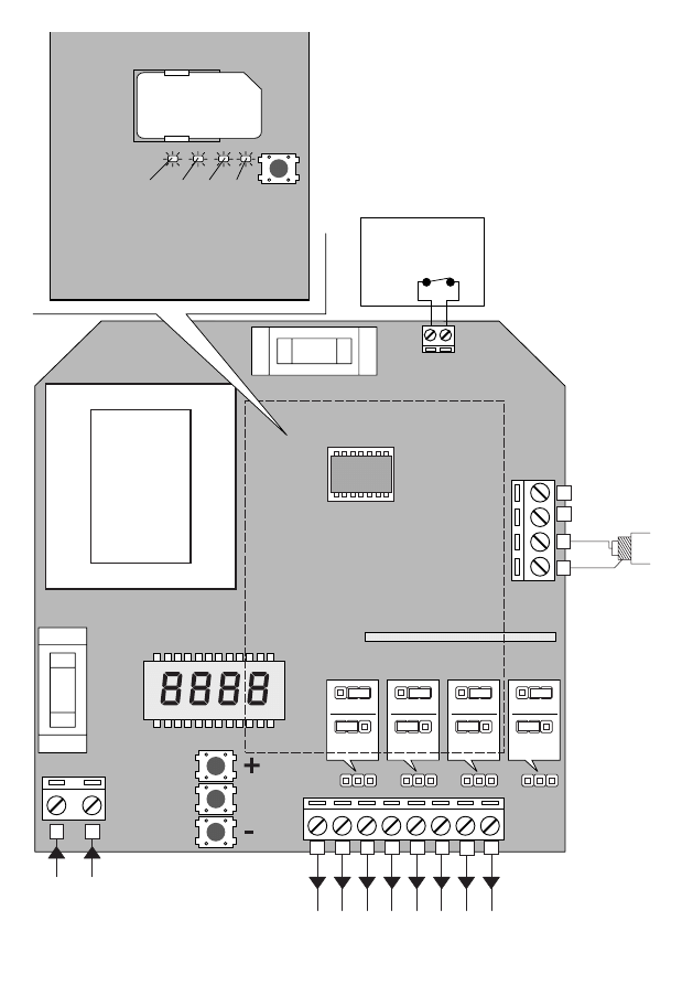
GSM four-channel receiver
GENERAL OPERATION:
The CALL device is composed of a 4-channel receiver and a GSM module assembled together.
This Instruction manual is divided in two parts: the first section describes the operation of the GSM module,
the second section refers to the radio module.
GSM MODULE
The presence of a GSM module allows to interact with the device through the use of a mobile phone.
It is in fact possible to:
- Activate a channel on the receiver through phone call (this is a no cost call as the device cuts the call
after a few rings with no answer);
- Activate one of the four channels through SMS.
Always by sending command signals (containing a safety password) via SMS it is also possible:
- to enter/cancel telephone numbers in/from the SIM memory of the Call device;
- to modify presetting of either number stored in memory;
- to activate/deactivate transmitters (rolling code);
- to modify the safety password;
- to ask the device the status of outcoming calls, the number and what mobile numbers are stored in
memory and their presetting, the number of active tx, whether a certain tx is active or not, the number
of SMS sent by Call;
- to lock/unlock the radio menu of the receiver so that no new transmitter codes are activated through the
receiver, but only through a mobile phone.
Moreover, every command signal requires a password (which can be modified).
Up to 250 telephone numbers can be stored in memory by changing presetting and passwords on channels.
When a mobile phone number is stored in the device, it is preset by default to activate channel 1 with the
vocal key and it is allowed to activate all the 4 channels through SMS.
Moreover, an alarm device (Normally closed device) can be connected to the CAll system. If the alarm is
activated, an alarm message will be sent to mobile phone numbers enabled for this function (the numbers
entered are not enabled by default for this function).
HOW TO CONNECT, SWITCH ON AND INITIALIZE THE SYSTEM:
Introduce a SIM card in the special seat in the device. There are no limits to the network operator. However,
the SIM that is intended for this use must be without PIN code. The SIM card must be in a mobile phone for
which, when switched on, the PIN request function is disabled.
The device can be connected to the 230V power mains (the device can be also connected to a 12V buffer
battery).
When the device is connected to the 230V power supply, the DL1 LED in the receiver is switched off. If the
device is connected to both battery and 230V power mains, the DL1 red LED of the receiver will flash (very)
slowly.
Once the receiver is powered, the yellow LED (DL1) and the green LED (DL4) will switch on. After a couple
of seconds, DL1 switches off, while DL4 stays on for about 15 seconds, and then starts to flash. After about
10 seconds, the latter switches off and the card enters the regular operating mode.
REGULAR OPERATING MODE OF THE GSM MODULE:
- The DL1 and DL2 yellow LED lights (TX and RX of the GSM module) flash alternatively.
- The green LED (DL4) flashes with a certain number of flips, followed by an interval (the number of
flips may vary from 1 to 5 and shows the level of the network signal that the module receives: 1=min,
5=max).
- When the module receives a SMS message, the DL3 red LED switches on with fixed light and then
switches off when the answer is sent (or in any case, when the command signal processing is
completed).
- If the red LED switches on and does not switch off, this means that the module is not able to send a SMS
(probably the credit of the SMS is exhausted).
RESETTING OF THE SIM CARD:
The SIM inserted in the GSM module can be reset.

This operation involves the following: erase message memory, erase address book, reset SMS counters,
new presetting of default password.
To reset the SIM card proceed as follows:
- Cut off power supply
- Press the module key (S1)
- Power the device keeping the key pressed
- The module switches on
- After approximately 15 seconds, the red LED switches on with fixed light (the key can be released)
- The red LED stays on for 2 about minutes. When it switches off, the operation is completed and the
message and address-book memory have been erased. The SMS counters have been reset and the
default password, which is 123456, has been restored.
- At this point, the module enters the normal operating mode.
COMMANDS SUPPORTED BY GSM:
- ASK THE MODULE GENERAL STATUS: status
- MODIFY THE ACCESS PASSWORD: modpsw
- ADD USER/S IN THE LIST OF ENABLED TELEPHONE NUMBERS: addnum
- MODIFY THE PERMITTED ACCESSES OF ONE OR MORE NUMBERS: modnum
- ASK THE STATUS OF PRESETTINGS AND PERMITTED ACCESSES RELATED TO THE NUMBER:
numstatus
- REMOVE USER FROM LIST OF ENABLED TELEPHONE NUMBERS: delnum
- READ LIST OF ENABLED TELEPHONES: readbook
- SET OF MESSAGE TEXT OF OUTPUT COMMAND SIGNAL: setcmdmsg
- RESET OF SENT SMS COUNTER: smsreset
- ADD A TX CODE IN THE RECEIVER CONNECTED TO MODULE: addtx
- DISABLE TX CODE IN THE RECEIVER CONNECTED TO MODULE: distx
- ASK STATUS OF TX CODE IN RECEIVER CONNECTED TO MODULE: testtx
- ACTIVATE TX INSERTION BLOCK THROUGH RECEIVER: setrxpsw
- DEACTIVATE TX INSERTION BLOCK THROUGH RECEIVER: resetrxpsw
- ASK OUTPUT STATUS OF RECEIVER: recstatus
The command signals are sent through a normal SMS message sent from a mobile phone to a number of
the SIM card placed in the CALL device. In its turn, for some commands, the device will reply with a SMS
message. The cost of these messages depends on the tariff and operator used.
The CALL device replies by default to the following:
- commands that require a reply:
status, numstatus, readbook, testtx, recstatus
- command messages:
modpsw, setrxpsw, resetrxpsw
- commands containing errors.
Moreover, the CALL device can send a SMS notice message also for the other command signals sent by
simply adding “?” before the command message.
The replies sent by the device vary according to the SMS sent and are described hereunder in the
description of command messages. The possible error replies, sent by the CALL device, change according
to the type of error made and are as follows:
POSSIBLE REPLIES OF ERROR:
“COMMAND MESSAGE NOT SET”
“PASSWORD NOT SET”
“COMMAND EXECUTION ERROR”
“COMMAND SYNTHAX ERROR”
“PASSWORD ERROR”
“ERRORE NON SUPPORTATO” ERROR NOT SET
“ERROR, MEMORY FULL”
“COMMAND UNKNOWN”
“PHONE NUMBER NOT PRESENT”
“ERROR, NO INTERNATIONAL DIALING CODE”
“UNAVAILABLE TELEPHONE NUMBER”
4
5

HOW TO ACTIVATE THE CHANNELS (with default presetting)
- CHANNEL ACTIVATION THROUGH LOCAL CALL: call the Call device with the mobile phone number
previously stored in memory, after 2 rings the call is cut off automatically and channel 1 is activated (the
channel to be activated with the phone call can be changed through the “modnum” command).
- CHANNEL ACTIVATION THROUGH SMS: through the mobile phone number previously memorised,
send a SMS to the Call device with “ch1” wording. As soon as the device receives the message,
channel 1 will be activated (or send the text ch2, ch3, ch4 according to the channel to be activated). As
described hereunder, the SMS messages to activate the channels can be modified.
N.B.: if a notice SMS is required by the Call device, the message sent shall be: “?ch1”, the answer will be:
“COMMAND OK”
IMPORTANT! The telephone numbers are valid only if preceded by an international dialling code:
+NN 339 123456789, where +NN is the international dialling code.
Use the formula +NN only, and not 00NN, which is not accepted by the system.
e.g.: +39 339 12456789 is a valid number, while 0039 339 123456789 is not valid.
If the international dialing code is not used, the system responds with an error message.
SYNTHAX OF COMMANDS:
1) REQUEST OF GENERAL STATUS OF THE MODULE:
This command signal permits to receive some information on the device:
the number of messages sent, the number of transmitter codes preset in memory, the software and
firmware version of the GSM module, the network operator to which the device is connected, the number
of mobile phones stored in memory.
status 123456
where:
status
command string
123456
access password (this is the default password if it has not modified yet or if
the module has been just initialized)
REPLY:
Sms sent: 0; Tx rec: 0; Sw:1.0.0; Fw:1.0.0.; Op:vodafone; phs:n/250
where:
Sms sent: 0
number of SMS sent from the last time counters have been reset
Tx rec: 0
number of transmitters stored in the receiver
Sw:1.0.0
software version of the GSM board
Fw:1.0.0.
firmware of the GSM module
Op:vodafone
network operator
phs:n/250
phonebook status: number of phone numbers stored in memory / maximum
phone numbers storable in memory
2) CHANGE IN THE ACCESS PASSWORD:
This command permits to modify the password which is entered every time a command is given.
It is possible to return to the default password by resetting the SIM.
modpsw 123456 112233
where:
modpsw command string
123456 default password (or password currently in use which is to be changed)
112233 new password (10 numeric digits max). Once the new password is preset, the old one
is no longer valid
REPLY :
“PASSWORD UPDATED”
3) ADD THE USER IN THE ENABLED PHONES LIST:
This command permits to add mobile phone numbers in the device memory.
New users can be added to the list of enabled mobile phones in two ways:
- Use of a mobile phone:
Remove the SIM card from the GSM module, insert it in a normal mobile phone and store the number
4
5

in memory in the “name” field. In the “number” field, instead, it is possible to choose whether to enter
“0” (in this case, the number will acquire default presetting and permitted access) or the 6-digit string of
presetting (se following section).
- Sending of a command through SMS:
proceed for all the other commands by sending the SMS to the module with the following command:
addnum 112233 +NN3391234567,n°2,n°3,n°4...
where
:
addnum
command string
112233
access password
+NN3391234567
telephone number to be added to the list
n°2,n°3,n°4
if more than one number are to be inserted with one single message, it is
sufficient to divide them with “,”
N.B.:
- When a number is stored in memory via SMS, it acquires the default permitted access and presetting
(see section “operation”). To modify these permitted accesses, see command “modnum”
- To allow for the correct operation of the phone call, the telephone must not have the function “hide
number” activated.
If a reply should be sent by the device, the command must be:
?addnum 112233 +NN3391234567;n°2;n°3;n°4
The reply will be : “USER ADDED”
4) HOW TO MODIFY THE PERMITTED ACCESS OF ONE OR MORE NUMBERS:
This command permits to modify the permitted access and presetting of one or more mobile phone num-
bers, or it permits or denies the possibility to activate some channels, change the combination call/channel
to be activated, call in the event of alarm.
modnum 112233 000000 +NN3391234567,n°2,n°3,n°4...
where
:
modnum
command string
112233
access password
000000
string regarding channel presetting and permitted accesses to channels *
+NN3391234567
enter the number the permitted access of which should be modified
n°2,n°3,n°4
more than one number can be modified by dividing them with “,”
* the string regarding channel presetting and permitted accesses to channels is composed of 6 digits:
Digit 1: alarm presetting:
“0” = the number will not be informed in case of alarm
“1” = the number will be informed in case of alarm
Digit 2: activation with phone call:
“0” = denied access (the phone call activates no channel)
“1” = the phone call activates channel 1
“2” = the phone call activates channel 2
“3” = the phone call activates channel 3
“4” = the phone call activates channel 4
Digit 3: activation of channel 1 by SMS:
“0” = denied access (channel 1 cannot be activated through SMS)
“1” = channel 1 can be activated (through the sending of SMS1)
Digit 4: activation of channel 2 by SMS:
“0” = the phone call activates channel (channel 2 cannot be activated through SMS)
“1” = channel 2 can be activated ( (through the sending of SMS2)
Digit 5: activation of channel 3 by SMS:
“0” = denied access (channel 3 cannot be activated through SMS)
“1” = channel 3 can be activated (through the sending of SMS3)
Digit 6: activation of channel 4 by SMS:
“0” = denied access (channel 4 cannot be activated through SMS)
“1” = channel 4 can be activated (through the sending of SMS4)
6
7

If a number, which was not previously memorised, is entered in among the numbers typed in the odnum
command, this number will be added to the list with presetting and permitted access indicated in the com-
mand.
If a reply should be sent by the device, the command shall be:
?modnum 112233 000000 +NN3391234567,n°2,n°3,n°4
The reply will be : “CONFIGURATION UPDATE OK”
5) STATUS REQUEST OF PRESETTING AND PERMITTED ACCESSES OF A NUMBER:
This command allows to know presetting (presetting of alarm and channel to be activated by phone call)
and permitted accesses (channels which can be activated by SMS) regarding one specific number stored
in memory.
numstatus 112233 +NN3391234567
where:
numstatus
command string
112233
access password
+NN3391234567
telephone number to be added to the list
REPLY:
ALLARM:ON/OFF,CALL:1/2/3/4,ch1:ON/OFF,ch2:ON/OFF,ch3:ON/OFF,ch4:ON/OFF
where:
ALLARM:ON/OFF
notice of activated/deactivated alarm
CALL:1/2/3/4
number showing the channel which can be activated by phone call
ch1:ON/OFF
activation status of channel 1 by SMS
ch2:ON/OFF
activation status of channel 2 by SMS
ch3:ON/OFF
activation status of channel 3 by SMS
ch4:ON/OFF
activation status of channel 4 by SMS
6) REMOVE USER FROM LIST OF ENABLED PHONES:
This command permits to remove one or more numbers from memory.
delnum 112233 +NN3391234567,n°2,n°3,n°4...
where:
delnum
command string
112233
access password
+NN3391234567
telephone number to be removed from list
n°2,n°3,n°4
more than one number can be modified by dividing them with “,”
If a reply should be sent by the device, the command shall be:
?delnum 112233 +NN3391234567;n°2;n°3;n°4
The reply will be: “USER DELETED”
7) READ LIST OF ENABLED PHONES:
This command permits to know the number of memorised phone numbers.
readbook 112233
where:
readbook
command string
112233
access password
REPLY:
n°1;n°2;n°3;
8) RESET OF SENT SMS COUNTER:
This command permits to reset the counter of SMS sent by the CALL device. This counter can be useful to
count the messages sent since the last recharge made in order to estimate the remaining credit.
smsreset 112233
where:
smsreset
command string
112233
access password
6
7

If a reply should be sent by the device, the command shall be:
?smsreset 112233
The reply will be: “COMMAND OK”
9) OUTPUT COMMAND MESSAGE:
This command permits to modify the text of channel activation SMS, so as to be able to combine a specific
output to an ID word of the device to be activated or deactivated.
(example: if the gate is connected to channel 1, the SMS linked to channel 1 can be modified with the word-
ing “GATE”)
setcmdmsg 112233 1 GATE
where:
setcmdmsg
command string
112233
access password
1
SMS to be modified (1-4)
GATE
channel activation string (20 digits max)
N.B.: the text of the 4 SMS is the default text: Ch1, Ch2, Ch3 and Ch4 (words corresponding to SMS1,
SMS2, SMS3, SMS4, respectively)
If a reply should be sent by the device, the command shall be:
?setcmdmsg 112233 1 GATE
The reply will be: “COMMAND MESSAGE SET”
10) ADD TRANSMITTER CODE IN THE RECEIVER CONNECTED TO MODULE:
This command permits to add a transmitter code to the receiver memory without necessarily gain access to
the control unit (the serial number of the transmitter to be entered must be known). Through this command
only 2-channel transmitters can be entered. To enter 4-channel transmitters proceed through the radio
Menu of the receiver (see instructions of RR.4).
addtx 112233 02D762D
where:
addtx
command string
112233
access password
02D762D
string of 7 hexadecimal digits (0 – F) representing the SN of the TX to be
added to the receiver memory
N.B.: the following is added by default to the TX added : key1>channel, key 2>channel 2.
The serial number of remote controls is indicated outside the remote controls in series, or it can be read
through the ADVANTAGE system.
If a reply should be sent by the device, the command shall be:
?addtx 112233 02D762D
The reply will be: “COMMAND OK”
11) HOW TO DISABLE THE TX PRESENT IN THE RECEIVER CONNECTED TO THE MODULO:
This command permits to disable a transmitter. This will remain stored in the receiver memory but it will not
activate any channel (to restore it, use command “addtx”)
distx 112233 02D762D
where:
distx
command string
112233
access password
02D762D
string of 7 hexadecimal digits (0 – F) representing the SN of the TX to be
disabled from the receiver memory
N.B.: To reset a disabled transmitter, enter it again with command “addtx”
If a reply should be sent by the device, the command shall be:
?distx 112233 02D762D
The reply will be: “COMMAND OK”
8
9

12) REQUEST OF TRANSMITTER STATUS IN RECEIVER CONNECTED TO THE MODULE:
This command permits to know whether a specific transmitter is enabled or not
testtx 112233 02D762D
where:
testtx
command string
112233
access password
02D762D
string of 7 hexadecimal digits (0 – F) representing the SN of the TX to
request the status
The reply will be one of the following
“TRANSMITTER ENABLED”
“TRANSMITTER DISABLED”
“TRANSMITTER NOT PRESENT”
13) ACTIVATION OF THE TRANSMITTER ENTER BLOCKTHROUGH RECEIVER:
This command permits to block the access to the radio menu functions of the receiver making it possible to
enter the new transmitters only through mobile phone (command “addtx”).
setrxpsw 112233
where:
setrxpsw
command string
112233
access password
REPLY:
“COMMAND OK”
14) DEACTIVATION OF TRANSMITTER ENTER BLOC THROUGH RECEIVER:
This command permits to reactivate the access to the radio menu functions of the receiver making it possi-
ble to store in memory new transmitters through both the use of a mobile phone and the normal functions
of the receiver.
resetrxpsw 112233
where:
resetrxpsw
command string
112233
access password
RISPOSTA:
“COMMAND OK”
15) STATUS REQUEST OF RECEIVER OUTPUTS:
This command permits to know the status of outputs, in other words whether they are activated or not
(preset outputs in impulsive mode will always how their OFF status).
recstatus 112233
where:
recstatus
command string
112233
access password
REPLY:
As a reply a string containing SMS activating messages regarding channels and showing their ON/OFF
status is sent
Note: To preset the channel operating modes (monostable/bistable/timed) see instructions of the RR 4
receiver.
8
9

ALARM FUNCTION
An alarm device (normally closed device) can be connected between Pin 4 and 5 of the ADV terminal board.
If the alarm triggers (the contact opens) the GSM module sends an alarm message to the mobile phone
numbers enabled for this function.
The message consists in a telephone call to the first number in memory enabled for this function (the order
is determined by the memorisation order in the SIM card). Whoever receives the call will be cable to hang up
and the alarm message will stop. Conversely, the call will stop automatically ad the second enabled number
will be called after 30 seconds, and so on.
Note: in order to be able to stop the alarm by hanging up, the mobile phone must have the telephone sec-
retary function disabled.
The command “modnum” allows for the entering of a phone number to receive the alarm message. In this
case, the number 1 must be typed in the first digit of the presetting string, for example:
modnum 112233 1XXXXX +NN3391234567
the number +NN3391234567 will be called in the event of alarm
modnum 112233 0XXXXX +NN3391234567
the number +NN3391234567 will not be called in the event of alarm
When the alarm triggers, the red LED of the GSM module switches on with fixed light and switches off
when someone cuts the call or when all phones have been called and the search of numbers to be called
completed
WARNINGS
When entering the customized password
(modpsw) and when customising the command strings (setcm-
dmsg), it is important not to leave blank spaces unintentionally.
The system, in fact, considers spaces as actual digits so that password “ABCDEFG ” differs from “ABC-
DEFG” as the first password features a blank at end of string.
For the same reason, when entering the various phone numbers for enable, disable purposes, etc., it is
important not to leave blank spaces between the various numbers, for ex.:
addnum 112233 +NN3391234567,+NN3391234568,+NN33912345679
is correct at the phone numbers are separated by a comma only.
while
addnum 112233 +NN3391234567, +NN3391234568, +NN33912345679
is incorrect and only the first number will be stored in memory.
10
11

RADIO RECEIVER MODULE
In this second part, the four channel radio receiver functions are described such as wire connections, output
configuration, memorising of transmitters, etc..
SPECIFICATIONS
- Four output, independent and freely configurable channels
- Rolling code radio receiver - 433.92MHz frequency
- Programming through built-in LCD display
- Standard memory for 512 transmitters. It can be replaced with MEM2048 module for 2048 transmitters
- Versions with 230VAC, 115VAC or 24VAC/CC power supply are available.
- Input for 12VDC emergency battery, with automatic charge.
INPUT/OUTPUT FUNCTIONS
Input, No.
Function
Description
1-2
Power supply
Input, 230Vac 50Hz (1-Phase/2-Neutral) in the 230V version
Input, 115Vac 60Hz (1-Phase/2-Neutral) in the 115V version
Input, 24 Vac/dc (1+ /2 -) in the 24V version
3-4
Channel 1
Output, channel 1. 230 Vac max 5A.
Normally Open (N.O.) Contact, switchable in Normally Closed (N.C.)
through jumper 1.
5-6
Channel 2
Output, channel 2. 230 Vac max 5A.
N.O. Contact, switchable in N.C. through jumper 2.
7-8
Channel 3
Output, channel 3. 230 Vac max 5A.
N.O. Contact switchable in N.C. through jumper 3.
9-10
Channel 4
Output, channel 4. 230 Vac max 5A.
N.O. Contact, switchable in N.C. through jumper 4.
11-12
Antenna
Antenna connection of the built-in radio module
(11-screen/12-signal).
13-14
Battery
Input for emergency battery, 12Vdc (13:- / 14:+).
It allows the operation of the receiver in case of power failure of the
mains, During the mains operation the battery is recharged.
Recharge time, about 15 hours for a battery 12V/1,2Ah.
Note:
The U2 memory can contain 512 rolling-code, 433.92MHz, transmitters maximum. If necessary, it can be
replaced with item MEM2048 which can contain up to 2048 different codes.
PROGRAMMING
The programming of the various functions of the control unit is carried out by using the LCD display in the
receiver and presetting the desired values in the programming menus described hereunder.
1 - Press the <PG> key, the display shows the first Parameters Menu “PAR”.
2 - By using the keys <+> or <->, select the desired Menu (PAR>>LOG>>RADIO>>....).
3 - Press the <PG> key, the display shows the first function available on the Menu.
4 - By using the keys <+> or <->, select the function to be modified.
5 - Press the <PG> key, the currently preset value for the selected function is displayed.
6 - By using the <+> or <-> keys, select the value to be assigned to the function.
7 - Press the <PG> key, “PRG” is displayed which means the programming has been successful.
Note:
You can return to the upper menu without making changes if you press the <+> and <-> keys simultaneously
in a Function Menu.
If you press the <+> and <-> keys simultaneously when the display is switched off, the card software version
is shown. Press PG to select the desired value. OK is shown to confirm a successful programming.
If either the <+> key or the <-> key are kept pressed, the increase/reduction of numeric values is accelerated
in the Time Menu.
After 60 sec wait, the receiver exits the programming mode and the display switches off.
Each single function, which is available in the control unit, is described in the following tables
10
11

PARAMETERS
MENU
FUNCTION
MCH1
The operating mode of channel 1 is preset.
The descriptions of the single submenus are shown hereunder:
IMp
Monostable. The relay activates for 1 sec when the corresponding key is pressed;
then the relay returns to its original status.
TG
Bistable. When the associated key in the transmitter is pressed, the relay activates.
It remains in its new status until the key is pressed again.
time
Timed. The relay activation time can be preset within a range of 1 to 600 seconds
(10 min).
Select the desired activation time between 1 and 600 seconds, then press OK to
store the val ue into memory.
MCH2
Same operating modes preset for MCH1.
MCH3
Same operating modes preset for MCH1.
MCH4
Same operating modes preset for MCH1.
LOGICS
MENU
FUNCTION
Add
Menu to type in the transmitter codes in memory.
The submenus are described hereunder:
CH1
The key is associated to channel 1. Press, within 5 sec, the transmitter key which is
to be associated to channel 1.
CH2
The key is associated to channel 2. Press, within 5 sec, the transmitter key which is
to be associated to channel 2.
CH3
The key is associated to channel 3. Press, within 5 sec, the transmitter key which is
to be associated to channel 3.
CH4
The key is associated to channel 4. Press, within 5 sec, the transmitter key which is
to be associated to channel 4.
DEL
Menu to erase previously typed in transmitter codes from memory.
The single submenus are described hereunder:
code
The receiver is in a waiting mode, waiting for a memorized transmitter key to be
pressed.
The transmitter is erased from the receiver memory.
indh
Remove a transmitter code for which the position in memory is know, see function
FIND>>Code.
res
The receiver memory is completely erased. All transmitter codes and relevant associations
and channel parameters are cancelled. A confirmation of the operation is being asked.
find
Search Menu for transmitter codes stored in memory.
The single submenus are described hereunder:
Code
The receiver is waiting for a code. Press any key on the transmitter; if this is stored
its position in memory is displayed.
N Tx
The number of transmitter codes stored in the receiver memory is displayed.
�������������������
����������������������������������������������������������������������������������������
Wyszukiwarka
Podobne podstrony:
chrystus jest zyciem mym ENG
Przegląd rozwiązań konstrukcyjnych wtryskarek (ENG)
Assembler ENG
Call option
Frequenzimetro eng 2003
PM [R2] Sylabus ENG
Call Of Cthulhu Dark Ages Bestiary
P000476 D Eng Main dimensions
Eurocode 3 Part 1 11 Pren 1993 1 11 (Eng)
Humulon and lupulon eng
Konwencja w sprawie zapobiegania i karania zbrodni ludobójstwa eng
Curriculum vitae Team III ENG
P000722 A Eng Lower preassembly
P000718 A Eng Vertical shaft assembly
M001882 B Eng Lower assembly
Cornish wordlist (Eng SWF trad)
2 WPT2009 Slovakia Eng Media Market Description
M000411 B Eng Propulsor painting instructions
więcej podobnych podstron