1
INTRODUCTION
GENERAL
This section has the description and repair procedures
for the fixed length container handling attachment.
DESCRIPTION
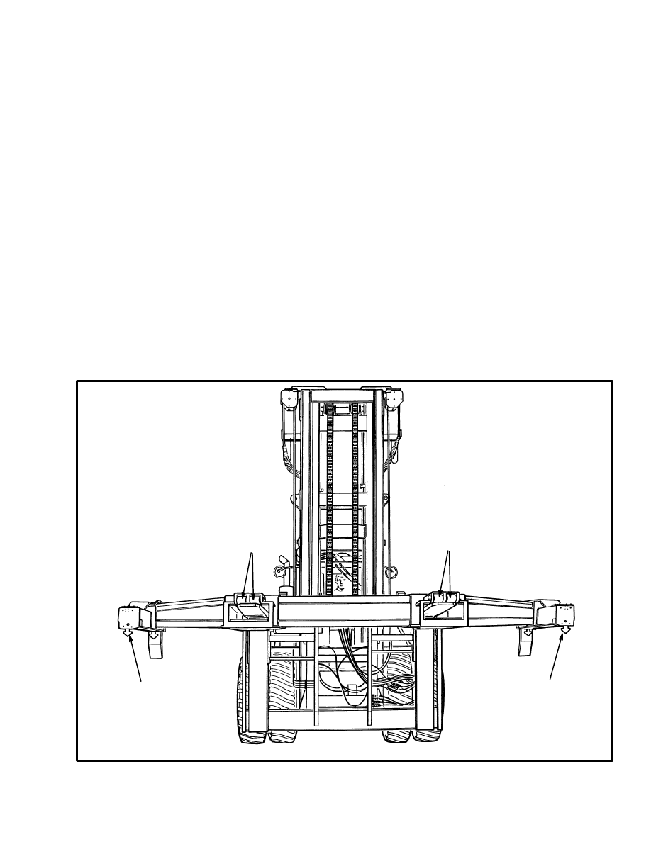
The fixed length container attachment can be either 6.1
m (20 feet) or 12.2 m (40 feet) wide. The attachment fits
on the forks of the lift truck. The slew cylinders or the
connector links connect the attachment to the carriage.
Both attachments operate the same and have the same
hydraulic and electrical circuit components. The hy-
draulic cylinders on the attachment are actuated by hy-
draulic pressure from the attachment control valve or
the selector valve.
OPERATION
The attachment has the following hydraulic compo-
nents: relief valves, slew cylinders, twist lock interlock
valves and twist lock cylinders and slew cylinders.
There are also six electric switches that are actuated by
the twist lock linkage and the interlock valves. The
switches are used to show if the attachment is correctly
attached to a container.
Twist Lock Circuit
Oil from the attachment control valve enters the attach-
ment at the relief valve for the twist lock circuit. When
the attachment is set on a container, the twist lock inter-
lock valves are actuated (opened). Actuation of two of
these valves opens the hydraulic circuit between the re-
lief valve and the twist lock cylinders. Actuation of the
other two interlock valves opens the hydraulic circuit
that connects the twist lock cylinders.
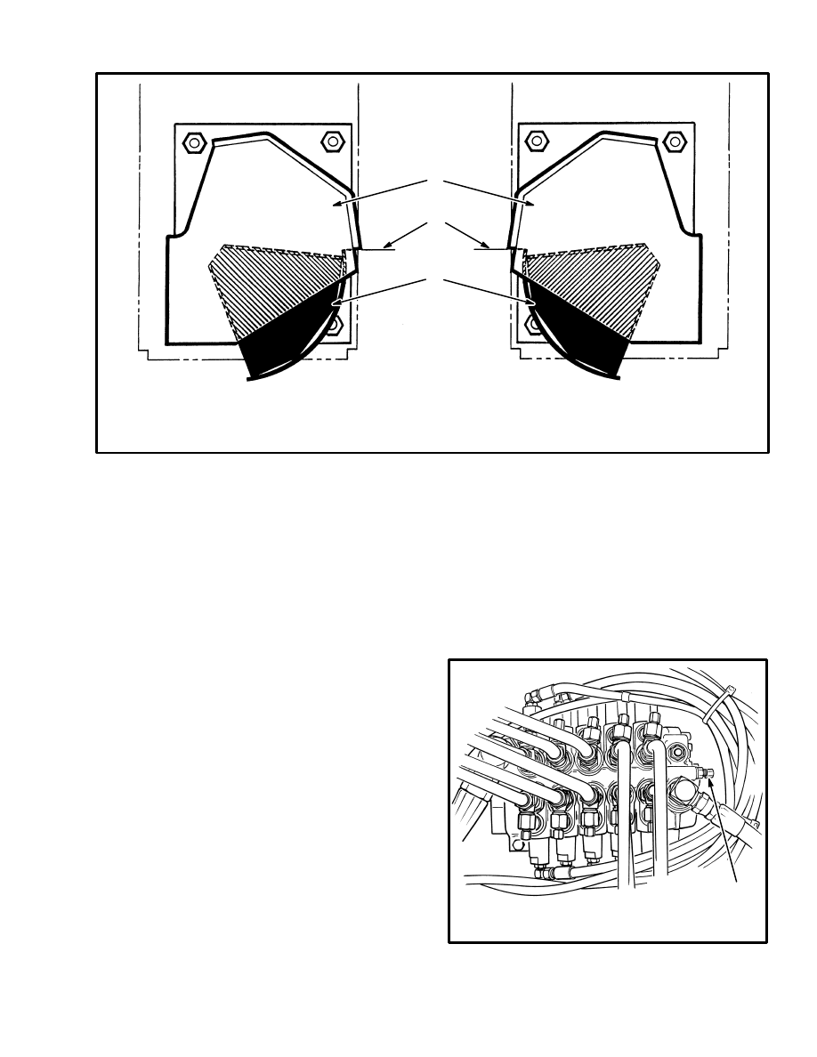
11202
FIGURE 1. FIXED LENGTH ATTACHMENT
1. FORK ROLLERS
2. TWIST LOCK
1
1
2
2
2
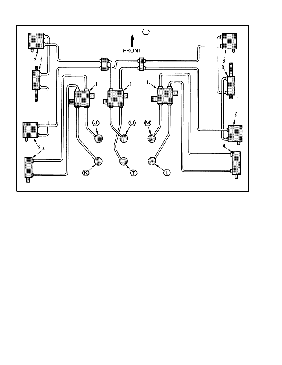
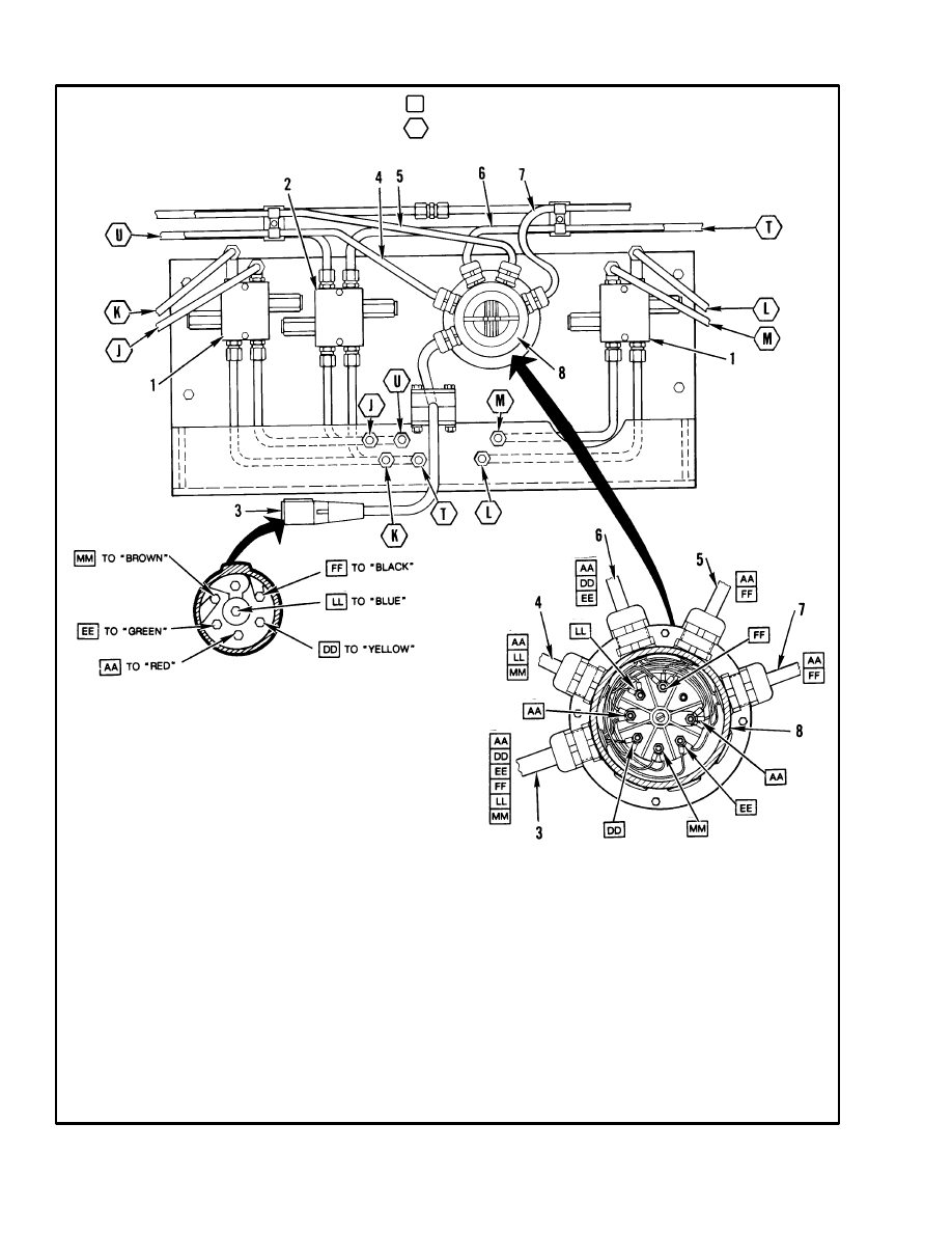
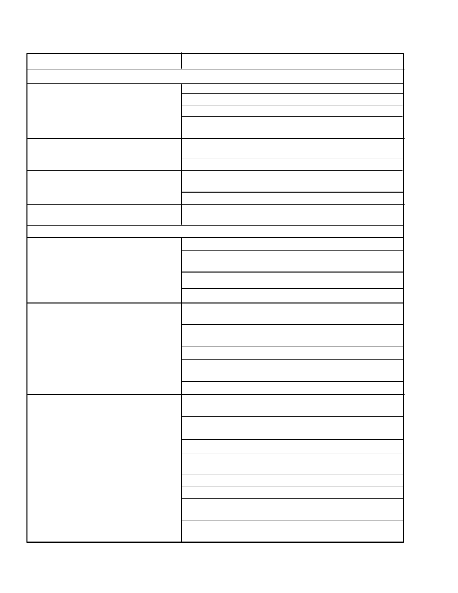
1. RELIEF VALVE
2. INTERLOCK VALVE
3. TWIST LOCK CYLINDER
4. SLEW CYLINDER
= HYDRAULIC LINES CODES
SEE TABLE 1.
FIGURE 2. HYDRAULIC DIAGRAM FOR ATTACHMENT (1 of 2)
10890
The oil flows in series from the interlock valve to the
twist lock cylinder and then to another interlock valve.
When the twist lock cylinders are actuated, they rotate
the twist locks. Each of the ports on the twist lock cylin-
ders have two internal holes; a primary port and an ori-
fice. When oil flows into a port, it will go through both
holes. The oil can also flow out of both holes at the other
end of the cylinder until the piston is completely against
the retainer. When the piston is against the retainer, oil
can continue to flow out of the orifice so that the other
cylinder can complete its stroke. When the attachment
lifts the container, the interlock valves return to the
closed position. With the interlock valves closed, the
twist locks are prevented from rotating.
The relief valve has two relief spools that are set at 8.4
MPa (1200 psi). Whenever the pressure in one side of
the circuit is more than 8.4 MPa (1200 psi) a spool
moves. When the spool moves, the oil under pressure
transfers to the return circuit.
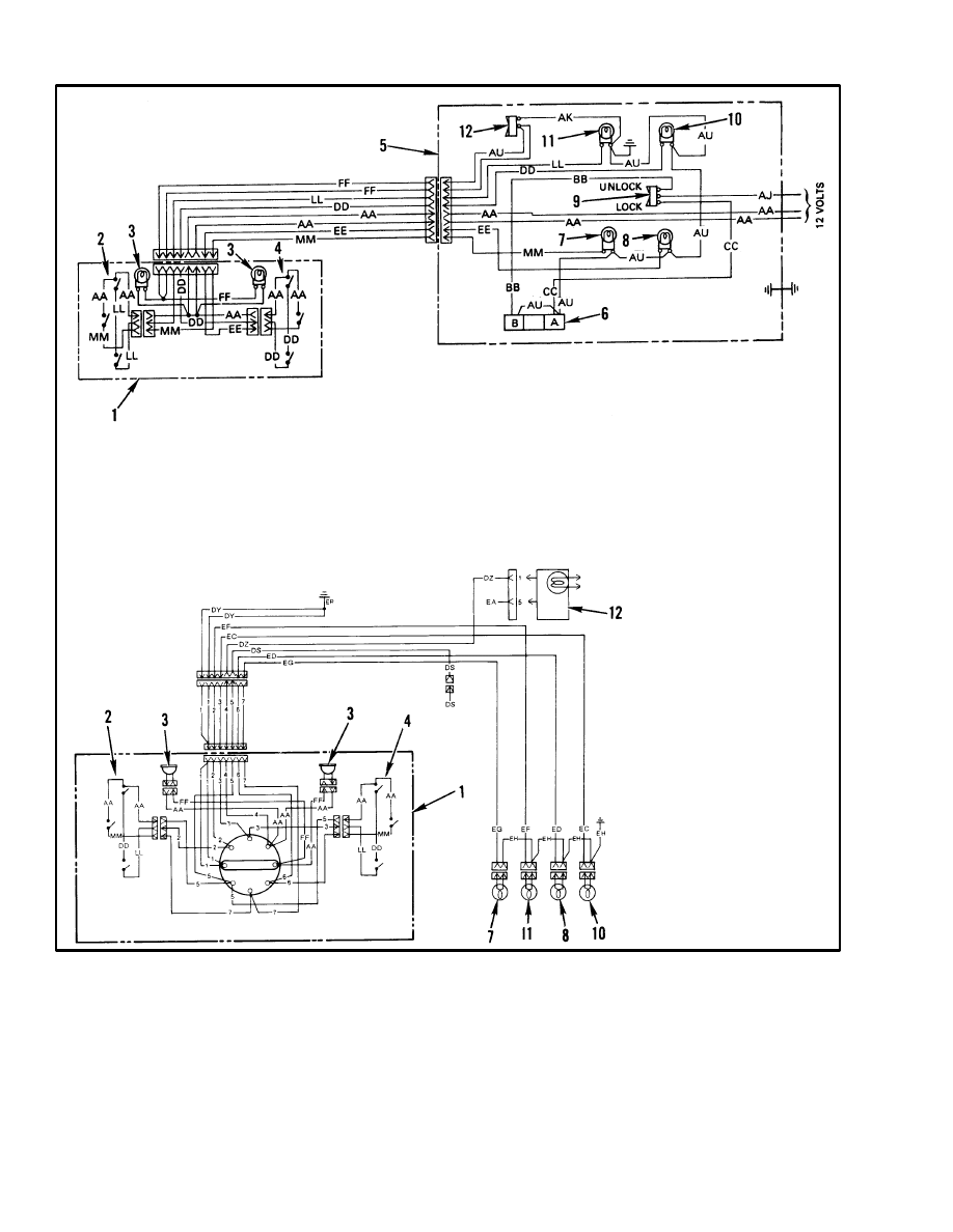
There are six electric switches (see FIGURE 3.) that are
actuated by the twist lock linkage. Four of the switches
are actuated by each of the plungers for the interlock
valves. The other two switches are actuated by the twist
lock cylinders. When the attachment is set on a con-
tainer, the plungers for each of the twist lock interlock
valves actuate the switches. When these switches are ac-
tuated, the two amber lights on the instrument panel will
illuminate indicating that the twist locks can be en-
gaged. (There is one light for each side of the attach-
ment.) When the twist locks are rotated to engage a con-
tainer, the twist lock cylinders actuate the two cylinder
switches. When these switches are actuated, the green
lights on the instrument panel will illuminate indicating
that the attachment is engaged with the container.
(There is one light for each side of the attachment.)
When the container is lifted, the amber lights will go off
and the green lights will stay on.
3
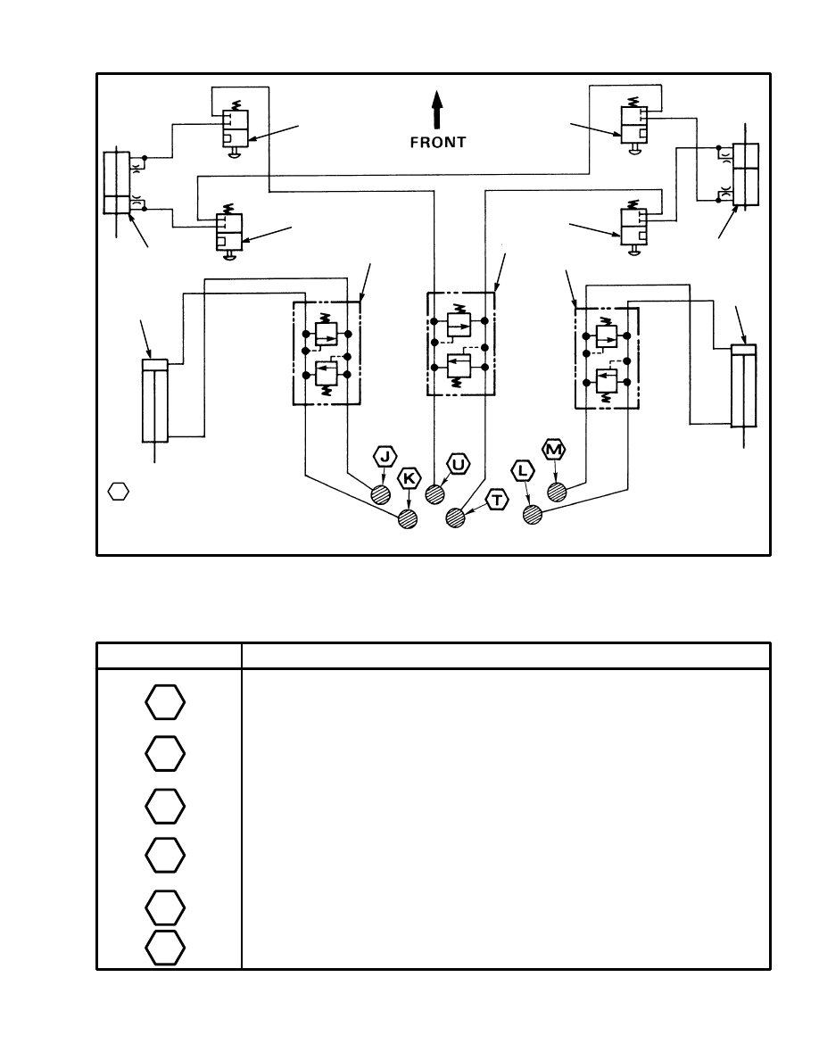
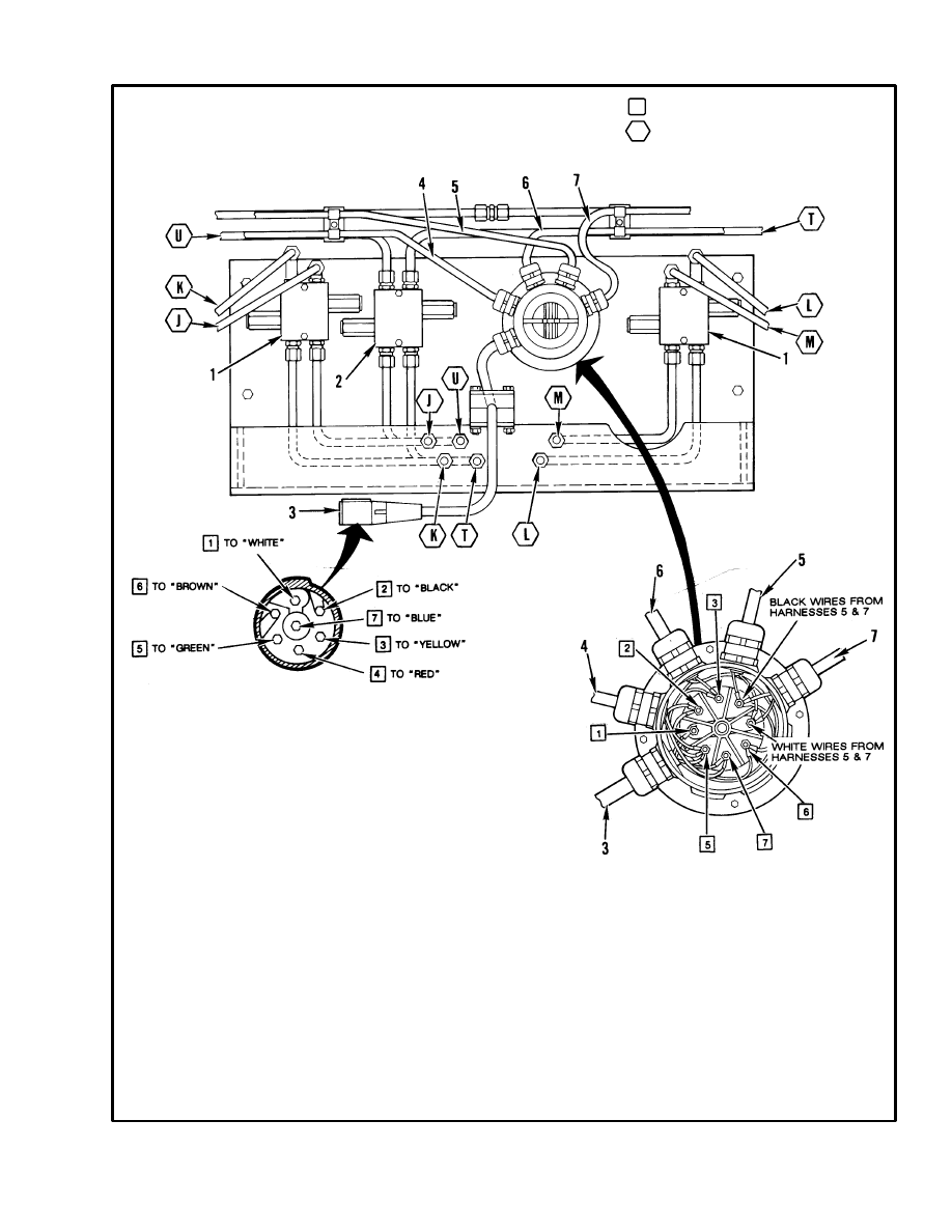
1. RELIEF VALVE
2. INTERLOCK VALVE
3. TWIST LOCK CYLINDER
4. SLEW CYLINDER
= HYDRAULIC LINES CODES
SEE TABLE 1.
FIGURE 2. HYDRAULIC DIAGRAM FOR ATTACHMENT (2 of 2)
10891
1
1
1
2
2
2
2
3
3
4
4
TABLE 1. HYDRAULIC LINE CODES FOR DIAGRAMS
CODE
FUNCTION
LEFT–HAND SLEW CYLINDER (PISTON SIDE) or
LEFT–HAND FORK POSITIONER CYLINDER (PISTON SIDE)
LEFT–HAND SLEW CYLINDER (ROD SIDE) or
LEFT–HAND FORK POSITIONER CYLINDER (ROD SIDE)
RIGHT–HAND SLEW CYLINDER (ROD SIDE) or
RIGHT–HAND FORK POSITIONER CYLINDER (ROD SIDE)
RIGHT–HAND SLEW CYLINDER (PISTON SIDE) or
RIGHT–HAND FORK POSITIONER CYLINDER (PISTON
SIDE)
TWIST LOCK (ENGAGE)
TWIST LOCK (DISENGAGE)
J
K
L
M
T
U
4
1. CONTAINER ATTACHMENT
2. LEFT–HAND TWIST LOCK
3. LIGHTS
4. RIGHT–HAND TWIST LOCK
5. OPERATOR COMPARTMENT
6. TWIST LOCK SOLENOID VALVE
FIGURE 3. ELECTRICAL SCHEMATIC FOR ATTACHMENT
7. GREEN LIGHT (LEFT–HAND)
8. GREEN LIGHT (RIGHT–HAND)
9. TWIST LOCK SWITCH
10. AMBER LIGHT (RIGHT–HAND)
11. AMBER LIGHT (LEFT–HAND)
12. LIGHT SWITCH
*Wire Code AU Is FF On Earlier Units
WIRE CODES
AA
AK
AJ
AU
BB
CC
DD
EE
FF
LL
MM
– RED
– BLACK
– BROWN
– BLACK
– BLUE
– ORANGE
– YELLOW
– GREEN
– BLACK
– BLUE
– WHITE
H17.00–32.00C (H370–700C)
H36.00–44.00B (H700–920B)
H16.00–30.00C (H360–650C)
H36.00–48.00C (H800–1050C)
WIRE CODES
AA
DD
FF
LL
MM
– BLACK
– BLUE
– WHITE
– GREEN
– WHITE
2 – BLACK OR GREEN
3 – BLACK OR GREEN
5 – BLACK
6 – BLACK OR WHITE
7 – BLACK OR WHITE
11125
12487
12488
Slew Circuit
The two slew cylinders can be installed between each
side of the carriage and the attachment. The slew cylin-
ders allow the attachment to pivot on the forks. Oil from
the attachment control valve or selector valve enters the
attachment at the relief valves for the slew cylinders.
When the right of left slew cylinder is actuated, it will
move the attachment. Whenever the pressure in one side
of the circuit for a cylinder is more than 10.5 MPa (1500
psi) a spool in the relief valve moves, the oil under pres-
sure transfers to the return circuit. This action only oc-
curs when the slew cylinders are actuated by the hand
levers.

5
REPAIRS
CONTAINER ATTACHMENT
Removal
Remove the container attachment from the lift truck us-
ing the following procedures.
1. Set the attachment on a loaded container or use a lift-
ing device to support the attachment. The 6.1 m (20 ft)
attachment weighs approximately 1860 kg (4100 lb).
The 12.2 m (40 ft) attachment weighs approximately
4220 kg (9300 lb). Shut off the engine. Put blocks under
the center of the attachment to support the weight of the
attachment.
WARNING
Do not disconnect any hydraulic lines when the en-
gine is running.
2. Disconnect the hydraulic lines to the attachment and
put caps on the open lines. Disconnect the electrical con-
nector at the attachment
3. Disconnect the slew cylinders or attachment connec-
tors from the attachment.
Installation
Install the container attachment on the lift truck using
the following procedures.
1. Move the forks so that they will fit in the fork pockets
of the attachment. Make sure each fork is the same dis-
tance from the outer edge of the carriage.
2. If the attachment is on a container, drive the lift truck
toward the attachment until the forks are completely in
the fork pockets. Shut off the engine. If the attachment is
not on a container, use a lifting device to raise the attach-
ment so that it can be installed. The 6.1 m (20 ft) attach-
ment weighs approximately 1860 kg (4100 lb). The 12.2
m (40 ft) attachment weighs approximately 4220 kg
(9300 lb).
3. Connect the hydraulic lines to the attachment. See
FIGURE 2. and FIGURE 3. for the arrangement of the
hydraulic lines. Connect the electrical connector to the
attachment.
4. Connect the slew cylinders or attachment connectors
between the carriage and the attachment. Use the hy-
draulic controls for the slew cylinders to move them so
that they can be connected.
5. Operate all of the controls for the attachment. Make
sure the controls operate as described in the OPERAT-
ING MANUAL.
HYDRAULIC VALVES
Removal (See FIGURE 4. and FIGURE 5.)
All of the hydraulic valves except the interlock valves
are installed on a plate at the back of the attachment. The
valves and plate can be removed as a unit or the valves
can be removed separately. When removing the valves,
make a note of the location and put identification tags on
the hydraulic lines.
Disassembly (See FIGURE 6.)
1. Disassemble the relief valves. Remove the cap for the
relief valve assembly.
2. Remove the adjustment screw, spring and plunger.
3. Remove the body for the relief valve assembly.
Cleaning and Inspection
Clean all of the parts in solvent. Inspect the parts for
damage.
Assembly (See FIGURE 6.)
1. Assemble the relief valves. Install the body for the re-
lief valve assembly.
2. Install the plunger, spring and adjustment screw.
3. Install the cap for the relief valve.
Installation (See FIGURE 4. and FIGURE 5.)
1. Install the relief valve on the plate. Connect the hy-
draulic lines.
2. Operate the system and check for leaks. Check the re-
lief pressure as described in Checks and Adjustments.
6
H16.00–30.00C (H360–650C) SHOWN.
FIGURE 4. HYDRAULIC VALVES AND ELECTRICAL CONNECTORS
1. INLINE CROSS RELIEF VALVE (SLEW CYLINDERS)
2. INLINE CROSS RELIEF VALVE (TWIST LOCKS)
3. ELECTRICAL PLUG
4. ELECTRICAL HARNESS (LH TWIST LOCK)
5. ELECTRICAL HARNESS (RH TWIST LOCK)
6. ELECTRICAL HARNESS (LH LIGHT)
7. ELECTRICAL HARNESS (RH LIGHT)
8. ELECTRICAL JUNCTION BOX
9. ELECTRICAL HARNESS, FROM LIFT TRUCK
= WIRE NUMBER
= HYDRAULIC LINES CODES
SEE TABLE 1.
H36.00–44.00B (H700–920B)
H17.00–32.00C (H370–700C)
11053
12563
7
H36.00–48.00C (H800–1050C) SHOWN.
FIGURE 5. HYDRAULIC VALVES AND ELECTRICAL CONNECTORS
1. INLINE CROSS RELIEF VALVE (SLEW CYLINDERS)
2. INLINE CROSS RELIEF VALVE (TWIST LOCKS)
3. ELECTRICAL PLUG
4. ELECTRICAL HARNESS (LH TWIST LOCK)
5. ELECTRICAL HARNESS (RH TWIST LOCK)
6. ELECTRICAL HARNESS (LH LIGHT)
7. ELECTRICAL HARNESS (RH LIGHT)
8. ELECTRICAL JUNCTION BOX
9. ELECTRICAL HARNESS, FROM LIFT TRUCK
= WIRE NUMBER
= HYDRAULIC LINES CODES
SEE TABLE 1.
11053
12563
8
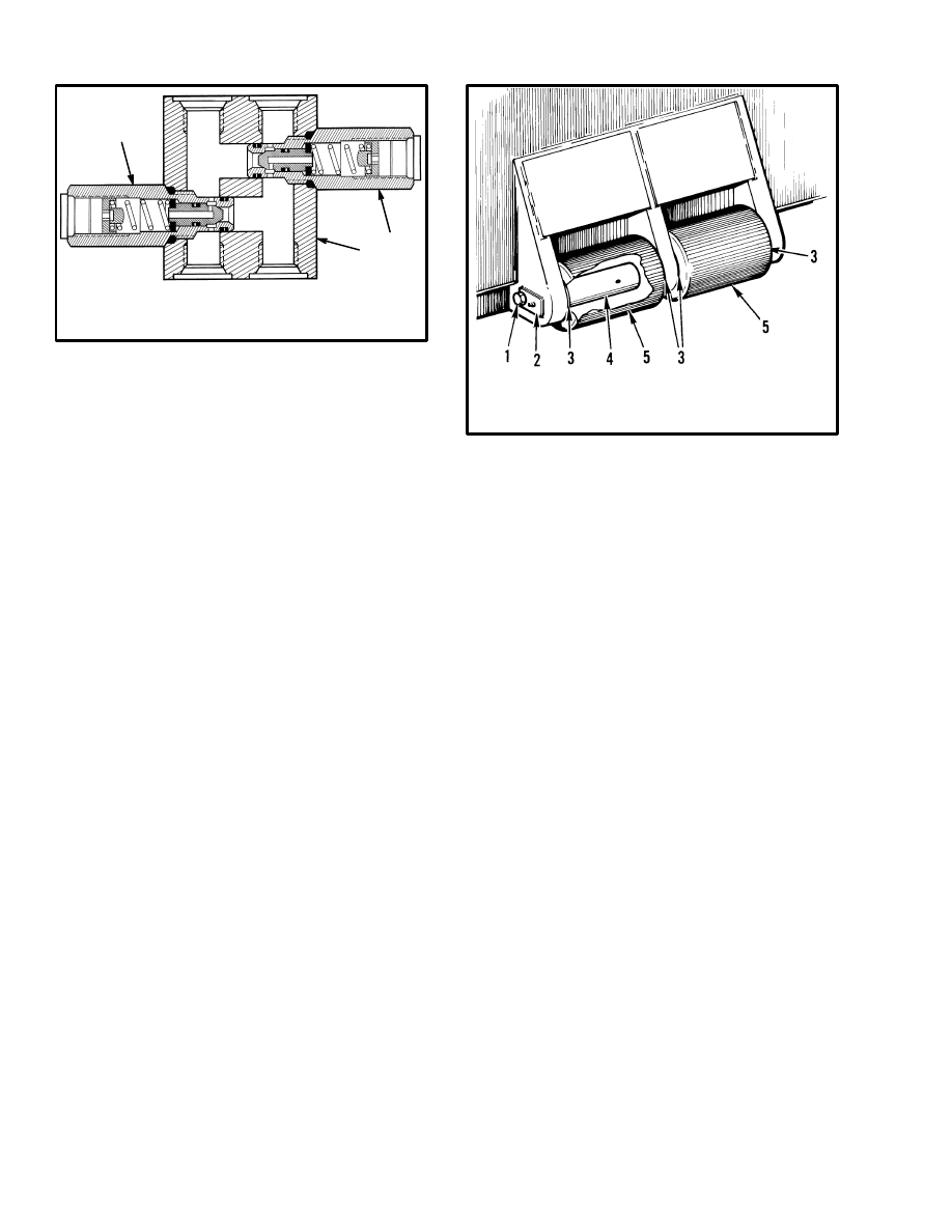
FIGURE 6. RELIEF VALVE
1. VALVE BODY
2. RELIEF CARTRIDGE
11105
1
2
2
FORK ROLLERS (See FIGURE 7.)
NOTE: Fork rollers are not used on container attach-
ments that are installed on dedicated carriages.
Removal and Disassembly
1. Remove the capscrew and keeper for the pin.
2. Push the pin from the frame. Remove the pin and roll-
er(s) and washers.
Cleaning and Inspection
Clean all parts in solvent. Inspect the rollers, bushings
and pins for damage.
Assembly and Installation (See FIGURE 7.)
1. If necessary, install new bushings in the rollers.
2. Lubricate the bushings and pins. Install the roller(s)
and washers in the frame. Install the pin.
3. Install the capscrew and keeper for the pin.
SLEW CYLINDERS
Removal
1. Put tags for identification on the hydraulic lines. Dis-
connect the hydraulic lines at the cylinder.
2. Remove the retainer pins and anchor pins from the
ends of the cylinder.
4. PIN
5. ROLLER
1. CAPSCREW
2. KEEPER
3. WASHER
FIGURE 7. FORK ROLLERS
3645
Disassembly (See FIGURE 8.)
1. Remove the retainer from the cylinder shell. Pull the
rod and piston from the shell.
2. Remove the seals from the retainer and piston.
Assembly (See FIGURE 8.)
1. Install the O–ring in the piston. Install the piston on
the rod. Tighten the nut for the piston to 407 to 441 N.m
(300 to 325 lbf ft).
2. Install the seal ring and wear ring on the piston. Install
the piston and rod in the shell.
3. Install the seal ring and O–ring on the retainer. Install
the rod seal and rod wiper in the retainer.
4. Install the retainer in the shell. Tighten the retainer to
475 to 542 N.m (350 to 400 lbf ft). It can be necessary to
make a special tool to tighten the retainer. See Figure 13
for the dimensions of the retainer.
Installation
1. Put the slew cylinder in position and install the anchor
pins. Install the retainer pins. Make sure the rod end of
the cylinders is connected to the carriage. Tighten the
capscrews for the anchor pins and the capscrews for the
rod end clamps to 77 N.m (57 lbf ft).
2. Connect the hydraulic lines to the cylinder. (See
FIGURE 1.)

9
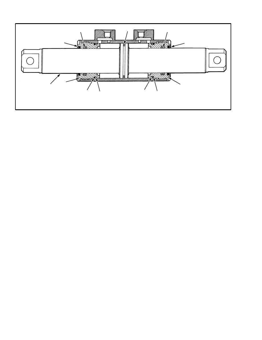
1. ROD
2. RETAINER
3. ROD WIPER
FIGURE 8. SLEW CYLINDER
4. ROD SEAL
5. PISTON
6. PISTON SEAL
7. WEAR RING
8. NUT
9. O–RING
10974
TWIST LOCKS
Disassembly (See FIGURE 9.)
Do the following procedures to disassemble either of the
twist lock assemblies.
1. Remove the twist lock indicators as follows:
a. Remove nuts and indicator flag from the bolt.
b. Remove the collar from the bolt.
c. Remove the nuts and the bracket from the outer
boom. Remove the bearing from the bracket.
2. Remove the covers on the outer boom for the twist
locks.
3. Remove the pins for the links between the twist lock
cylinder and the twist locks. Remove the links.
4. Disconnect the hydraulic lines at the twist lock cylin-
der. Put caps on the openings. Disconnect the wires at
the switch near the cylinder.
5. Remove the capscrews that hold the cylinder mount
plate to the outer boom. Remove the cylinder from the
mount plate. Use the following procedure to disassem-
ble the cylinder (see FIGURE 10.):
a. Remove the retainers from the ends of the cylin-
der shell. Remove the rod and piston from the
shell.
b. Remove the seals from the retainers and piston.
c. Clean the parts in solvent and check for damage.
1. TWIST LOCK
2. RETAINER
3. BUSHING
4. CRANK
5. LINK
6. COVER
FIGURE 9. TWIST LOCK ARRANGEMENT
3483
10
1. ROD
2. RETAINER
3. ROD WIPER
4. ROD SEAL
FIGURE 10. TWIST LOCK CYLINDER
5. PISTON SEAL
6. O–RING
7. BACK–UP RING
10963
1
3
4
4
3
2
5
7
6
6
7
2
6. Remove the crank from the twist lock. Remove the six
capscrews and retainers for the twist lock. Push the twist
lock from the outer boom.
7. Disconnect the hydraulic lines at the twist lock inter-
lock valve. Put identification tags on the lines. Put caps
on the openings. Remove the two cap–screws and the
twist lock interlock valve.
8. Remove the plunger assembly and switch for the in-
terlock valve.
Assembly (See FIGURE 9.)
Use this procedure to assemble any of the twist lock as-
semblies.
1. Install the plunger assembly and the mount for the
switch for the twist lock interlock valve. Install the stud,
spring, bar and nut for the plunger. Use Loctite on the
stud and install to the height shown in FIGURE 11.
Install the assembly as shown in FIGURE 12.
2. Install the twist lock interlock valve. Adjust the clear-
ance as shown in FIGURE 11. or FIGURE 12.
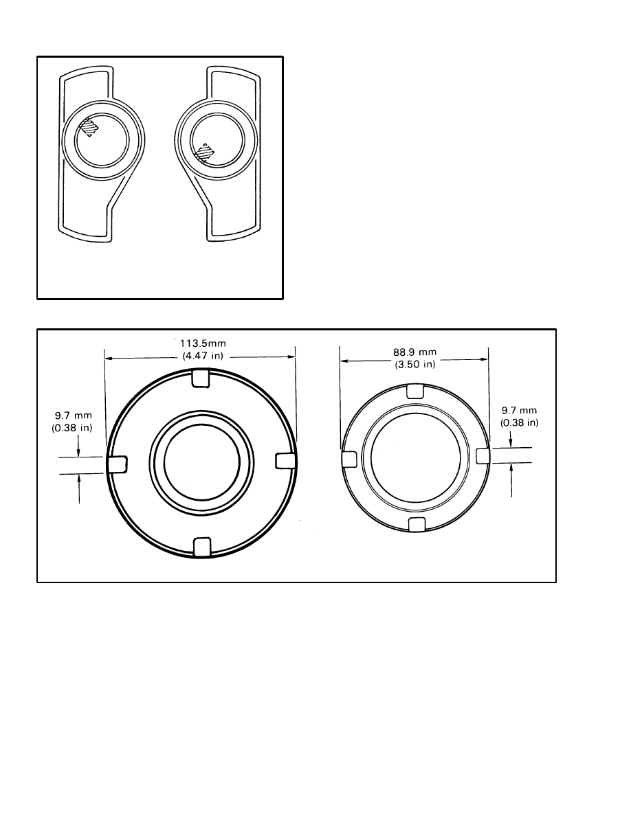
3. Install the twist lock in the boom. If Universal twist
locks are used, make sure they are installed in the correct
locations. See FIGURE 13. when installing the Univer-
sal twist locks. Install the retainers for the twist lock.
Make sure the chamfer on the retainer is toward the top.
Tighten the capscrews for the retainers to 149 N.m (110
lbf ft). Install the crank and key on the twist lock.
Tighten the bolt for the crank to 20 N.m (14 lbf ft).
4. Do the following procedure to assemble the twist lock
cylinder (see FIGURE 10.):
a. Install the seals on the piston.
b. Install the O–ring and back–up ring on the retain-
er. Install the rod seal and rod wiper in the retain-
er.
c. Install the retainers in the cylinder shell. Tighten
the retainers to 407 to 475 N.m (300 to 350 lbf ft).
It can be necessary to make a special tool to
tighten the retainers. The dimensions of the re-
tainers is shown in FIGURE 14.
5. Install the twist lock cylinder on the mount plate. In-
stall the U–bolts and nuts. Make sure the fittings on the
cylinder are straight down.
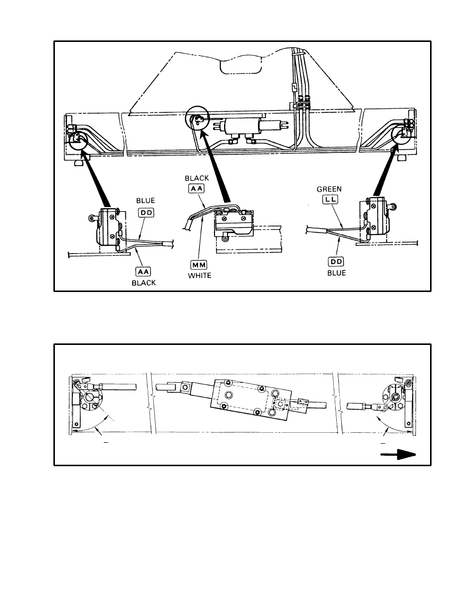
6. Install the mount plate in the outer boom. Install the
switch as follows:
a. Install the switch on the bracket. Connect the
wires to the switch. (See FIGURE 3.)
b. Install the bracket, but leave the capscrew loose.
c. Extend the cylinder rod through its complete
stroke toward the switch.
d. Move the bracket and switch toward the cylinder
until the switch opens. Check that the circuit be-
tween the two terminals is not energized.
e. Tighten the capscrews for the bracket. Operate
the cylinder and check the operation of the
switch.
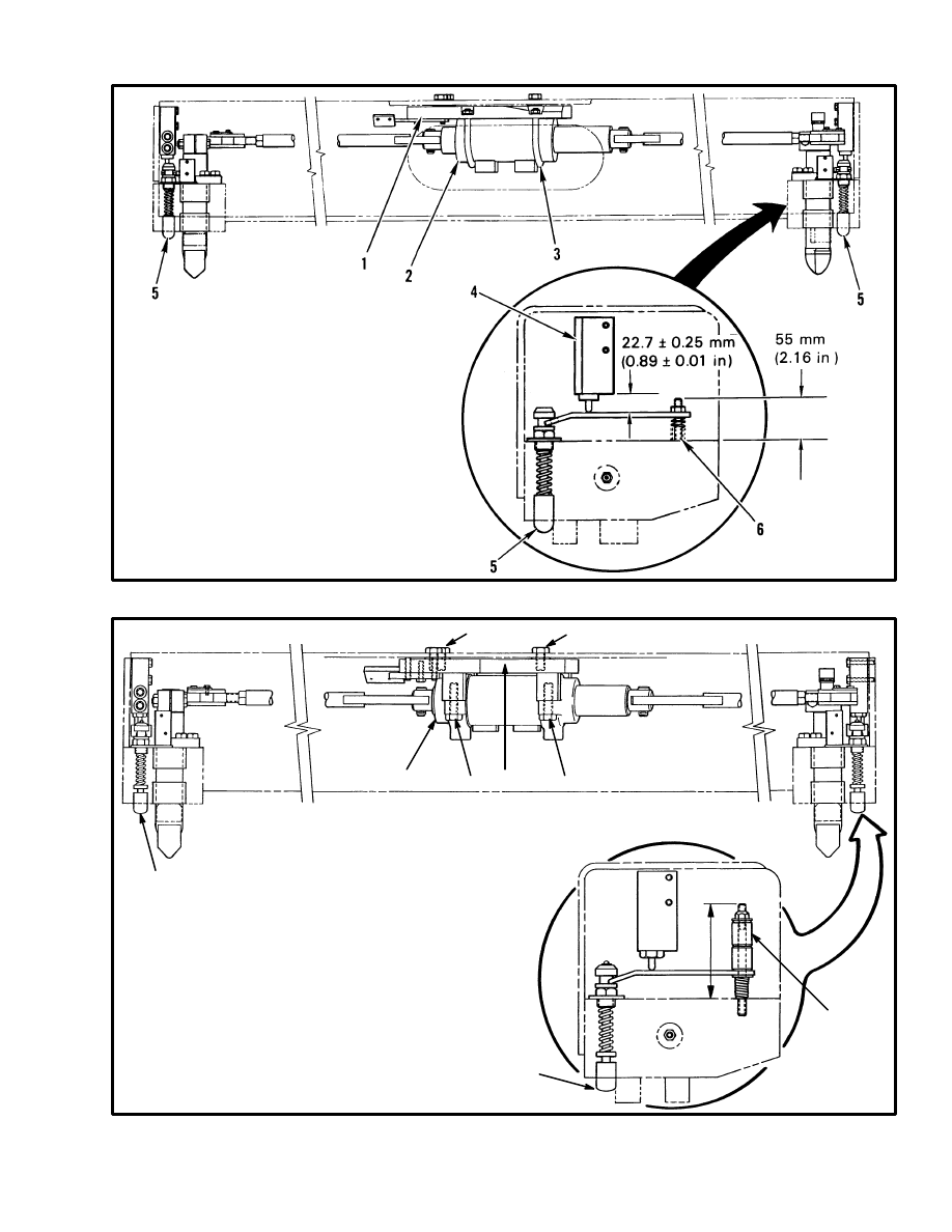
11
FIGURE 11. INSTALLATION OF THE INTERLOCK VALVE (EARLIER PRODUCTION)
1. MOUNT PLATE
2. CYLINDER
3. U–BOLT
4. INTERLOCK VALVE
5. PLUNGER ASSEMBLY
6. STUD
10976
FIGURE 12. INSTALLATION OF THE INTERLOCK VALVE (LATER PRODUCTION)
1. MOUNT PLATE
2. CYLINDER
3. CAPSCREW (4)
[TIGHTEN TO 215 N.m (160 lbf ft)]
4. INTERLOCK VALVE
5. PLUNGER ASSEMBLY
6. LINK ADJUSTMENT
7. CAPSCREW (3)
[TIGHTEN TO 155 N.m (115 lbf ft)]
10976
7
7
1
2
3
3
5
5
120 mm
(4.72 in)
6
12
FIGURE 13. UNIVERSAL TWIST LOCKS
RIGHT FRONT
AND
LEFT REAR
LEFT FRONT
AND
RIGHT REAR
11107
7. Install the links between the twist lock cylinder and
the twist locks. Connect the links to the cylinder and
twist locks using the pins.
8. Connect the hydraulic lines to the interlock valves and
the twist lock cylinder.
9. Adjust the links for the twist locks as follows:
a. Rotate the twist locks to the unlocked position.
Make sure the cylinder rod is extended all the
way in the unlocked position.
b. Adjust each of the rod ends on the links so that the
crank on the twist lock is at 45
degrees
.
c. Also check that each twist lock is aligned with the
guides on the bottom of the outer boom (disen-
gaged position).
FIGURE 14. DIMENSION OF RETAINERS
SLEW CYLINDER
TWIST LOCK CYLINDER
11106
13
FIGURE 15. INSTALLATION OF THE SWITCHES
10979
FIGURE 16. ADJUSTMENT OF THE TWIST LOCK LINKAGE
RIGHT–HAND END SHOWN
IN UNLOCKED POSITION.
45
°
+ 2
°
LIFT TRUCK
45
°
+ 2
°
10975
10. Install the covers for the twist locks.
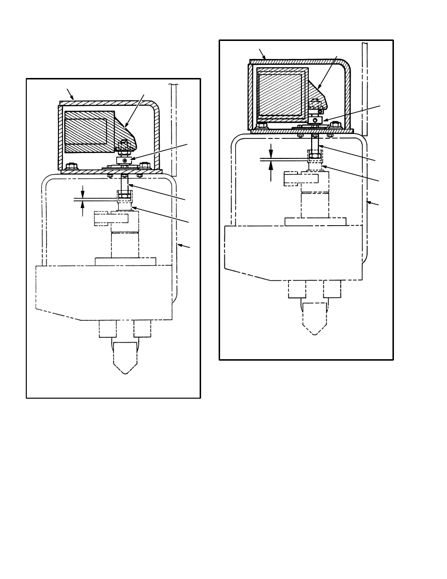
11. Install the twist lock indicators as follows:
a. Install the bolt in the socket on the twist lock.
b. Install the bearing in the bracket. Install the
bracket on the outer boom.
c. Install the collar on the bolt. Rotate the collar un-
til it touches the bearing. Make sure there is ap-
proximately 5.0 mm (0.2 in) between the bolt and
the socket. (See FIGURE 17. or FIGURE 18.)
Tighten the set screw on the collar.
14
d. Install the nuts and indicator on the bolt. Align the
indicator flags as shown in FIGURE 19., then
tighten the nut to 54 N.m (40 lbf ft).
1. BRACKET
2. INDICATOR
3. COLLAR
4. BOLT
5. OUTER BOOM
6. TWIST LOCK
FIGURE 17. ALIGNMENT OF INDICATORS
(EARLIER PRODUCTION)
5.0 mm
(0.2 in)
10977
1
2
3
4
5
6
1. BRACKET
2. INDICATOR
3. COLLAR
4. BOLT
5. OUTER BOOM
6. TWIST LOCK
FIGURE 18. ALIGNMENT OF INDICATORS
(LATER PRODUCTION)
5.0 mm
(0.2 in)
10977
1
2
3
4
5
6
15
FIGURE 19. ALIGNMENT OF THE INDICATOR FLAGS
3490
LEFT–HAND END
RIGHT–HAND END
1. INDICATOR FLAG
2. BRACKET
3. WITH TWIST LOCKS ENGAGED,
ALIGN THE FLAGS WITH
BRACKETS AS SHOWN
1
2
3
CHECKS AND ADJUSTMENTS
CHECK THE PRESSURE OF THE RELIEF
VALVES
NOTE: Check the pressure of the relief valves at the
check port on the attachment control valve. The relief
valves are not adjustable. If the pressure of a valve is not
correct, replace the valve.
1. Connect a 20 MPa (3000 psi) gauge to the check port
on the attachment control valve. (See FIGURE 20.) In-
stall the container handling attachment, making sure the
hydraulic lines are connected correctly.
2. Operate the hydraulic system until the oil is at operat-
ing temperature, [54
°
to 66
°
C (130
°
to 150
°
F)]. Run the
engine at 2500 rpm and operate the control lever for the
circuit being tested. When the cylinder stops moving the
hydraulic pressure will reach the relief setting. Check
the gauge at the check port.
3. The correct pressure settings are as follows:
a. Relief valves for slew cylinders or fork positioner
cylinders: 10.5 MPa (1500 psi).
b. Relief valves for twist lock cylinders: 8.4 MPa
(1200 psi)
1. CHECK PORT
FIGURE 20. LOCATION OF CHECK PORT
11043
1
16
All indicator lights are out.
Amber lights are out.
Green lights are out.
Hydraulic functions do not operate.
Slew cylinder does not operate.
Twist lock cylinders do not
operate, or they operate slowly.
Indicator lights stay on.
Fuses are damaged.
Connector at attachment is disconnected or damaged.
Wiring harness on attachment is damaged.
Wiring harness to operator compartment is disconnected
or damaged.
Switch or switches at interlock valve(s) are damaged or
not adjusted correctly.
Bulbs are damaged. Wires are disconnected.
Switch or switches at twist lock cylinders are damaged or
not adjusted correctly.
Bulbs are damaged. Wires are disconnected.
Switches at twist lock cylinders or interlock valves are dam-
aged or not adjusted correctly.
PROBLEM
CAUSE
ELECTRICAL SYSTEM
HYDRAULIC SYSTEM
No oil flow to the pressure reduction valve.
Relief valve in attachment control valve is not adjusted
correctly.
Pressure reduction valve is not adjusted correctly.
Oil pressure to remote control valve is not correct.
Oil flow from pressure reduction valve to the remote
control valve is not correct.
Pilot oil flow from remote control valve to attachment
control valve is not correct.
Relief valves for slew cylinders do not operate correctly.
Hydraulic lines are not connected, are damaged or have
a restriction.
Slew cylinder has damaged internal parts.
Oil flow from pressure reduction valve to the twist lock so-
lenoid valve is not correct.
Pilot oil flow from twist lock solenoid to attachment control
valve is not correct.
Relief valve for twist lock circuit does not operate correctly.
Hydraulic lines are not connected, are damaged or have
a restriction.
Twist lock cylinder(s) has damaged internal parts.
Twist lock linkage is damaged.
TROUBLESHOOTING
Twist lock interlock valve(s) are damaged or not
adjusted correctly.
The plungers on the interlock valves are not fully
depressed.

17
Document Outline
- INTRODUCTION
- REPAIRS
- CHECKS AND ADJUSTMENTS
- TROUBLESHOOTING
Wyszukiwarka
Podobne podstrony:
897996 5000SRM0668 (05 1997) UK EN
1452929 2200SRM0679 (11 2003) UK EN
1466205 2100SRM0735 (11 2004) UK EN
897986 1600SRM0658 (03 1997) UK EN
897493 1600SRM0512 (11 1995) UK EN
1554636 8000SRM1080 (11 2004) UK EN
1466193 2200SRM0755 (11 2001) UK EN
897116 1200SRM0334 (11 1997) US EN
897497 2000SRM0516 (11 1995) UK EN
910233 1300SRM0061 (02 1997) UK EN
897820 2200SRM0595 (11 1995) UK EN
1475871 1800SRM0785 (11 2003) UK EN
897988 4000SRM0660 (05 1997) UK EN
więcej podobnych podstron