
EUROPEAN STANDARD
NORME EUROPÉENNE
EUROPÄISCHE NORM
FINAL DRAFT
prEN 1991-1-5
May 2003
ICS 91.010.30
Will supersede ENV 1991-2-5:1997
English version
Eurocode 1: Actions on structures - Part 1-5: General actions -
Thermal actions
Eurocode 1: Actions sur les structures - Partie 1-5: Actions
sur les structures
This draft European Standard is submitted to CEN members for formal vote. It has been drawn up by the Technical Committee CEN/TC
250.
If this draft becomes a European Standard, CEN members are bound to comply with the CEN/CENELEC Internal Regulations which
stipulate the conditions for giving this European Standard the status of a national standard without any alteration.
This draft European Standard was established by CEN in three official versions (English, French, German). A version in any other
language made by translation under the responsibility of a CEN member into its own language and notified to the Management Centre has
the same status as the official versions.
CEN members are the national standards bodies of Austria, Belgium, Czech Republic, Denmark, Finland, France, Germany, Greece,
Hungary, Iceland, Ireland, Italy, Luxembourg, Malta, Netherlands, Norway, Portugal, Slovak Republic, Spain, Sweden, Switzerland and
United Kingdom.
Warning : This document is not a European Standard. It is distributed for review and comments. It is subject to change without notice and
shall not be referred to as a European Standard.
EUROPEAN COMMITTEE FOR STANDARDIZATION
C O M I T É E U R O P É E N D E N O R M A L I S A T I O N
E U R O P Ä I S C H E S K O M I T E E F Ü R N O R M U N G
Management Centre: rue de Stassart, 36 B-1050 Brussels
© 2003 CEN
All rights of exploitation in any form and by any means reserved
worldwide for CEN national Members.
Ref. No. prEN 1991-1-5:2003 E

prEN 1991-1-5: 2003 (E)
2
CONTENTS
Page
FOREWORD .............................................................................................................. 4
B
ACKGROUND TO THE
E
UROCODE
P
ROGRAMME
........................................................... 4
S
TATUS AND FIELD OF APPLICATION OF
E
UROCODES
..................................................... 5
N
ATIONAL
S
TANDARDS IMPLEMENTING
E
UROCODES
..................................................... 5
L
INKS BETWEEN
E
UROCODES AND PRODUCT HARMONIZED TECHNICAL SPECIFICATIONS
(EN
S AND
ETA
S
) ....................................................................................................... 6
A
DDITIONAL INFORMATION SPECIFIC TO
EN 1991-1-5 ................................................... 6
N
ATIONAL
A
NNEX FOR
EN 1991-1-5 ........................................................................... 6
SECTION 1 GENERAL............................................................................................. 8
1.1
S
COPE
............................................................................................................. 8
1.2
N
ORMATIVE REFERENCES
.................................................................................. 8
1.3
A
SSUMPTIONS
................................................................................................... 8
1.4
D
ISTINCTION BETWEEN PRINCIPLES AND APPLICATION RULES
................................ 9
1.5
D
EFINITIONS
..................................................................................................... 9
1.6
S
YMBOLS
....................................................................................................... 10
SECTION 2 CLASSIFICATION OF ACTIONS ....................................................... 13
SECTION 3 DESIGN SITUATIONS........................................................................ 14
SECTION 4 REPRESENTATION OF ACTIONS .................................................... 15
SECTION 5 TEMPERATURE CHANGES IN BUILDINGS..................................... 17
5.1 G
ENERAL
.......................................................................................................... 17
5.2 D
ETERMINATION OF TEMPERATURES
.................................................................... 17
5.3 D
ETERMINATION OF TEMPERATURE PROFILES
....................................................... 18
SECTION 6 TEMPERATURE CHANGES IN BRIDGES ........................................ 20
6.1
B
RIDGE DECKS
................................................................................................ 20
6.1.1
Bridge deck types ................................................................................... 20
6.1.2 Consideration of thermal actions ............................................................... 20
6.1.3 Uniform temperature component ............................................................... 20
6.1.4
Temperature difference components ...................................................... 24
6.1.5
Simultaneity of uniform and temperature difference components ........... 30
6.1.6
Differences in the uniform temperature component between different
structural elements ............................................................................................. 31
6.2
B
RIDGE
P
IERS
................................................................................................ 31
6.2.1
Consideration of thermal actions ............................................................ 31
6.2.2
Temperature differences......................................................................... 31
SECTION 7 TEMPERATURE CHANGES IN INDUSTRIAL CHIMNEYS,
PIPELINES, SILOS, TANKS AND COOLING TOWERS......................................... 32
7.1
G
ENERAL
....................................................................................................... 32
7.2
T
EMPERATURE COMPONENTS
........................................................................... 32

prEN 1991-1-5: 2003 (E)
3
7.2.1
Shade air temperature ............................................................................ 32
7.2.2
Flue gas, heated liquids and heated materials temperature ................... 33
7.2.3
Element temperature .............................................................................. 33
7.3
C
ONSIDERATION OF TEMPERATURE COMPONENTS
.............................................. 33
7.4
D
ETERMINATION OF TEMPERATURE COMPONENTS
.............................................. 33
7.5
V
ALUES OF TEMPERATURE COMPONENTS
(
INDICATIVE VALUES
) ........................... 34
7.6
S
IMULTANEITY OF TEMPERATURE COMPONENTS
................................................. 34
ANNEX A (NORMATIVE) ISOTHERMS OF NATIONAL MINIMUM AND MAXIMUM
SHADE AIR TEMPERATURES ............................................................................... 37
A.1
G
ENERAL
....................................................................................................... 37
A.2
M
AXIMUM AND MINIMUM SHADE AIR TEMPERATURE VALUES WITH AN ANNUAL
PROBABILITY OF BEING EXCEEDED
P OTHER THAN
0,02................................................ 37
ANNEX B
............................................................................................................ 40
(NORMATIVE) TEMPERATURE DIFFERENCES FOR VARIOUS SURFACING
DEPTHS
............................................................................................................ 40
ANNEX C
............................................................................................................ 43
(INFORMATIVE) COEFFICIENTS OF LINEAR EXPANSION ................................ 43
ANNEX D
............................................................................................................ 45
(INFORMATIVE) TEMPERATURE PROFILES IN BUILDINGS AND OTHER
CONSTRUCTION WORKS ...................................................................................... 45
BIBLIOGRAPHY ...................................................................................................... 47

prEN 1991-1-5: 2003 (E)
4
Foreword
This document (prEN 1991-1-5) has been prepared by Technical Committee
CEN/TC250 "Structural Eurocodes", the secretariat of which is held by BSI.
This document is currently submitted to the Formal Vote.
Annexes A and B are normative. Annexes C and D are informative.
This European Standard will supersede ENV 1991-2-5:1997.
Background to the Eurocode Programme
In 1975, the Commission of the European Communities decided on an action
programme in the field of construction, based on article 95 of the treaty. The
objective of the programme was the elimination of technical obstacles to trade and
the harmonization of technical specifications.
Within this action programme, the Commission took the initiative to establish a set of
harmonised technical rules for the design of construction works which, in a first
stage, would serve as an alternative to the national rules in force in the Member
States and, ultimately, would replace them.
For fifteen years, the Commission, with the help of a Steering Committee with
Representatives of Member States, conducted the development of the Eurocodes
programme, which led to the first generation of European codes in the 1980's.
In 1989, the Commission and the Member States of the EU and EFTA decided, on
the basis of an agreement between the Commission and CEN, to transfer the
preparation and the publication of the Eurocodes to CEN through a series of
mandates, in order to provide them with a future status of European Standard (EN).
This links
de facto the Eurocode with the provisions of all the Council's Directives
and/or Commission's Decisions dealing with European Standards (e.g. the Council
Directive 89/106/EEC on construction products - CPD - and Council Directives
93/37/EEC, 92/50/EEC and 89/440/EEC on public works and services and equivalent
EFTA Directives initiated in pursuit of settings up the internal market).
The Structural Eurocode programme comprises the following standards generally
consisting of a number of Parts:
EN 1990
Eurocode:
Basis of Structural Design
EN 1991
Eurocode 1: Actions on structures
EN 1992
Eurocode 2: Design of concrete structures
EN 1993
Eurocode 3: Design of steel structures
EN 1994
Eurocode 4: Design of composite steel and concrete structures
EN 1995
Eurocode 5: Design of timber structures
EN 1996
Eurocode 6: Design of masonry structures

prEN 1991-1-5: 2003 (E)
5
EN 1997
Eurocode 7: Geotechnical design
EN 1998
Eurocode 8: Design of structures for earthquake resistance
EN 1999
Eurocode 9: Design of aluminium alloy structures
Eurocode standards recognize the responsibility of regulatory authorities in each
Member State and have safeguarded their right to determine values related to
regulatory safety matters at national level where these continue to vary from State to
State.
Status and field of application of Eurocodes
The Member States of the EU and EFTA recognize that Eurocodes serve as
reference documents for the following purposes:
–
as a means of providing compliance of building and civil engineering works with
the essential requirements of Council Directive 89/106/EEC, particularly Essential
Requirement N
o
1 - Mechanical resistance and stability - and Essential
Requirement N
o
2 - Safety in case of fire;
–
as a basis for specifying contracts for construction works and related engineering
services;
–
as a framework for drawing up harmonized technical specifications for
construction products (ENs and ETAs)
The Eurocodes, as far as they concern the construction works themselves, have a
direct relationship with the Interpretative Documents referred to in Article 12 of the
CPD, although they are of a different nature from harmonized product standards.
Therefore, technical aspects arising from the Eurocodes work need to be adequately
considered by CEN Technical Committees and/or EOTA Working Groups working on
product standards with a view to achieving a full compatibility of these technical
specifications with the Eurocodes.
The Eurocode standards provide common structural design rules for everyday use
for the design of whole structures and component products of both a traditional and
an innovative nature. Unusual forms of construction design conditions are not
specifically covered and additional expert consideration will be required by the
designer in such cases.
National Standards implementing Eurocodes
The National Standards implementing Eurocodes will comprise the full text of the
Eurocode (including any annexes), as published by CEN, which may be preceded by
a National title page and National foreword, and may be followed by a National annex
(informative).

prEN 1991-1-5: 2003 (E)
6
The National annex (informative) may only contain information on those parameters
which are left open in the Eurocode for national choice, known as Nationally
Determined parameters, to be used for the design of buildings and civil engineering
works to be constructed in the country concerned, i.e.:
–
values and/or classes where alternatives are given in the Eurocode,
–
values to be used where a symbol only is given in the Eurocode,
–
country specific data (geographical, climatic, etc.), e.g. snow map,
–
the procedure to be used where alternative procedures are given in the EN
Eurocode.
It may also contain
–
decisions on the application of informative annexes,
–
references to non-contradictory complementary information to assist the user to
apply the Eurocode.
Links between Eurocodes and product harmonized technical specifications
(ENs and ETAs)
There is a need for consistency between the harmonized technical specifications for
construction products and the technical rules for works. Furthermore, all the
information accompanying the CE Marking of the construction products which refer to
Eurocodes should clearly mention which Nationally Determined Parameters have
been taken into account.
Additional information specific to EN 1991-1-5
EN 1991-1-5 gives design guidance for thermal actions arising from climatic and
operational conditions on buildings and civil engineering works.
Information on thermal actions induced by fire is given in EN 1991-1-2.
EN 1991-1-5 is intended for clients, designers, contractors and relevant authorities.
EN 1991-1-5 is intended to be used with EN 1990, the other Parts of EN 1991 and
EN 1992-1999 for the design of structures.
In the case of bridges, the National annexes specify whether the general non-linear
or the simplified linear temperature components should be used in design
calculations.
In the case of chimneys, references should be made to EN 13084-1 for thermal
actions from operating processes.
National annex for EN 1991-1-5
This standard gives alternative procedures, values and recommendations for classes
with notes indicating where national choices may have to be made. Therefore the
National Standard implementing EN
1991-1-5 should have a National annex

prEN 1991-1-5: 2003 (E)
7
containing all Nationally Determined Parameters to be used for the design of
buildings and civil engineering works to be constructed in the relevant country.
National choice is allowed in EN 1991-1-5 through clauses:
- 5.3(2) (Tables 5.1, 5.2 and 5.3)
- 6.1.1 (1)
- 6.1.2(2)
- 6.1.3.1(4)
- 6.1.3.2(1)
- 6.1.3.3(3)
- 6.1.4(2)
- 6.1.4.1(1)
- 6.1.4.2(1)
- 6.1.4.3(1)
- 6.1.4.4(1)
- 6.1.5(1)
- 6.1.6(1)
- 6.2.1(1)P
- 6.2.2(1)
- 6.2.2(2)
- 7.2.1(1)
- 7.5(3)
- 7.5(4)
- A.1(1)
- A.1(3)
- A.2(2)
- B(1) (Tables B.1, B.2 and B.3)

prEN 1991-1-5: 2003 (E)
8
Section 1
General
1.1
Scope
(1) EN 1991-1-5 gives principles and rules for calculating thermal actions on
buildings, bridges and other structures including their structural elements. Principles
needed for cladding and other appendages of buildings are also provided.
(2) This Part describes the changes in the temperature of structural elements.
Characteristic values of thermal actions are presented for use in the design of
structures which are exposed to daily and seasonal climatic changes. Structures not
so exposed may not need to be considered for thermal actions.
(3) Structures in which thermal actions are mainly a function of their use (e.g. cooling
towers, silos, tanks, warm and cold storage facilities, hot and cold services etc) are
treated in Section 7. Chimneys are treated in EN 13084-1.
1.2
Normative references
This European Standard incorporates, by dated or undated reference, provisions
from other publications. These normative references are cited at the appropriate
places in the text and the publications are listed hereafter. For dated references,
subsequent amendments to or revisions of any of these publications apply to this
European Standard only when incorporated in it by amendment or revision. For
undated references the latest edition of the publication referred to applies (including
amendments).
EN 1990:2002
Eurocode: Basis of structural design
pEN 1991-1-6
Eurocode 1: Actions on structures
Part 1.6: General actions - Actions during execution
EN 13084-1
Free-standing industrial chimneys
Part 1: General requirements
ISO 2394 General principles on reliability for structures
ISO 3898 Basis of design of structures - Notations. General symbols
ISO 8930 General principles on reliability for structures. List of equivalent terms
1.3
Assumptions
(1)P The general assumptions of EN 1990 also apply to this Part.

prEN 1991-1-5: 2003 (E)
9
1.4
Distinction between principles and application rules
(1)P The rules in EN 1990:2002, 1.4 also apply to this Part.
1.5
Terms and definitions
For the purposes of this European Standard, the definitions given in EN 1990,
ISO 2394, ISO 3898 and ISO 8930 and the following apply.
1.5.1
thermal actions
thermal actions on a structure or a structural element are those actions that arise
from the changes of temperature fields within a specified time interval
1.5.2
shade air temperature
the shade air temperature is the temperature measured by thermometers placed in a
white painted louvred wooden box known as a “Stevenson screen”
1.5.3
maximum shade air temperature
T
max
value of maximum shade air temperature with an annual probability of being
exceeded of 0,02 (equivalent to a mean return period of 50 years), based on the
maximum hourly values recorded
1.5.4
minimum shade air temperature
T
min
value of minimum shade air temperature with an annual probability of being
exceeded of 0,02 (equivalent to a mean return period of 50 years), based on the
minimum hourly values recorded
1.5.5
initial temperature
T
0
the temperature of a structural element at the relevant stage of its restraint
(completion)
1.5.6
cladding
the part of the building which provides a weatherproof membrane. Generally cladding
will only carry self weight and/or wind actions
1.5.7
uniform temperature component
the temperature, constant over the cross section, which governs the expansion or
contraction of an element or structure (for bridges this is often defined as the
“effective” temperature, but the term “uniform” has been adopted in this part)

prEN 1991-1-5: 2003 (E)
10
1.5.8
temperature difference component
the part of a temperature profile in a structural element representing the temperature
difference between the outer face of the element and any in-depth point
1.6
Symbols
(1) For the purposes of this Part of Eurocode 1, the following symbols apply.
NOTE: The notation used is based on ISO 3898
(2) A basic list of notations is provided in EN 1990, and the additional notations below
are specific to this Part.
Latin upper case letters
R
thermal resistance of structural element
R
in
thermal resistance at the inner surface
R
out
thermal resistance at the outer surface
T
max
maximum shade air temperature with an annual probability of being
exceeded of 0,02 (equivalent to a mean return period of 50 years
T
min
minimum shade air temperature with an annual probability of being
exceeded of 0,02 (equivalent to a mean return period of 50 years
T
max,p
maximum shade air temperature with an annual probability of being
exceeded
p (equivalent to a mean return period of 1/p)
T
min,p
minimum shade air temperature with an annual probability of being
exceeded
p (equivalent to a mean return period of 1/p)
T
e.max
maximum uniform bridge temperature component
T
e.min
minimum uniform bridge temperature component
T
0
initial temperature when structural element is restrained
T
in
air temperature of the inner environment
T
out
temperature of the outer environment
∆
T
1
,
∆
T
2
,
values of heating (cooling) temperature differences
∆
T
3
,
∆
T
4

prEN 1991-1-5: 2003 (E)
11
∆
T
U
uniform temperature component
∆
T
N, exp
maximum expansion range of uniform bridge temperature component
(
T
e.max
≥
T
0
)
∆
T
N, con
maximum contraction range of uniform bridge temperature component
(
T
0
≥
T
e.min
)
∆
T
N
overall range of uniform bridge temperature component
∆
T
M
linear temperature difference component
∆
T
M,heat
linear temperature difference component (heating)
∆
T
M,cool
linear temperature difference component (cooling)
∆
T
E
non-linear part of the temperature difference component
∆
T
sum of linear temperature difference component and non-linear part of
the temperature difference component
∆
T
p
temperature difference between different parts of a structure given by
the difference of average temperatures of these parts
Latin lower case letters
h
height of the cross-section
k
1
,
k
2
coefficients for calculation of maximum (minimum) shade air
k
3
,
k
4
temperature with an annual probability of being exceeded,
p, other than
0,02
k
sur
surfacing factor for linear temperature difference component
p
annual probability of maximum (minimum) shade air temperature being
exceeded (equivalent to a mean return period of 1/
p years)
u,c
mode and scale parameter of annual maximum (minimum)
shade air temperature distribution
Greek lower case letters
α
T
coefficient of linear expansion (1/°C)
λ
thermal conductivity

prEN 1991-1-5: 2003 (E)
12
ω
N
reduction factor of uniform temperature component for combination
with temperature difference component
ω
M
reduction factor of temperature difference component for combination
with uniform temperature component

prEN 1991-1-5: 2003 (E)
13
Section 2
Classification of actions
(1)P Thermal actions shall be classified as variable and indirect actions, see EN
1990:2002, 1.5.3 and 4.1.1.
(2) All values of thermal actions given in this Part are characteristic values unless it is
stated otherwise.
(3) Characteristic values of thermal actions as given in this Part are 50-year return
values, unless stated otherwise, e.g. for transient design situations.
NOTE: For transient design situations, the related values of thermal actions may be derived
using the calculation method given in A.2.

prEN 1991-1-5: 2003 (E)
14
Section 3
Design situations
(1)P Thermal actions shall be determined for each relevant design situation identified
in accordance with EN 1990.
NOTE: Structures not exposed to daily and seasonal climatic and operational temperature
changes may not need to be considered for thermal actions.
(2)P The elements of loadbearing structures shall be checked to ensure that thermal
movement will not cause overstressing of the structure, either by the provision of
movement joints or by including the effects in the design.
prEN 1991-1-5: 2003 (E)
15
Section 4
Representation of actions
(1) Daily and seasonal changes in shade air temperature, solar radiation, re-
radiation, etc., will result in variations of the temperature distribution within individual
elements of a structure.
(2) The magnitude of the thermal effects will be dependent on local climatic
conditions, together with the orientation of the structure, its overall mass, finishes
(e.g. cladding in buildings), and in the case of building structures, heating and
ventilation regimes and thermal insulation.
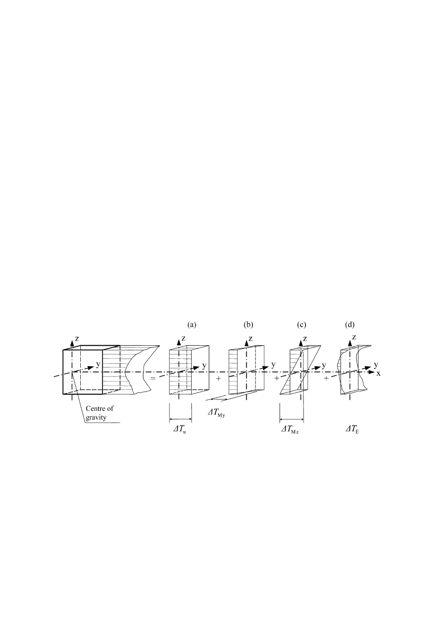
(3) The temperature distribution within an individual structural element may be split
into the following four essential constituent components, as illustrated in Figure 4.1:
a) A uniform temperature component,
∆
T
u
;
b) A linearly varying temperature difference component about the
z-z axis,
∆
T
MY
;
c) A linearly varying temperature difference component about the
y-y axis,
∆
T
MZ
;
d) A non-linear temperature difference component,
∆
T
E
. This results in a system of
self-equilibrated stresses which produce no net load effect on the element.
Figure 4.1: Diagrammatic representation of constituent components of a
temperature profile
(4) The strains and therefore any resulting stresses, are dependent on the geometry
and boundary conditions of the element being considered and on the physical
properties of the material used. When materials with different coefficients of linear
expansion are used compositely the thermal effect should be taken into account.
(5) For the purpose of deriving thermal effects, the coefficient of linear expansion for
a material should be used.

prEN 1991-1-5: 2003 (E)
16
NOTE: The coefficient of linear expansion for a selection of commonly used materials is
given in annex C.

prEN 1991-1-5: 2003 (E)
17
Section 5
Temperature changes in buildings
5.1 General
(1)P Thermal actions on buildings due to climatic and operational temperature
changes shall be considered in the design of buildings where there is a possibility of
the ultimate or serviceability limit states being exceeded due to thermal movement
and/or stresses.
NOTE 1: Volume changes and/or stresses due to temperature changes may also be
influenced by:
a) shading of adjacent buildings,
b) use of different materials with different thermal expansion coefficients and heat transfer,
c) use of different shapes of cross-section with different uniform temperature.
NOTE 2: Moisture and other environmental factors may also affect the volume changes of
elements.
5.2 Determination of temperatures
(1) Thermal actions on buildings due to climatic and operational temperature
changes should be determined in accordance with the principles and rules provided
in this Section taking into account national (regional) data and experience.
(2)P The climatic effects shall be determined by considering the variation of shade air
temperature and solar radiation. Operational effects (due to heating, technological or
industrial processes) shall be considered in accordance with the particular project.
(3)P In accordance with the temperature components given in Section 4, climatic and
operational thermal actions on a structural element shall be specified using the
following basic quantities:
a) A uniform temperature component
∆
T
u
given by the difference between the
average temperature
T of an element and its initial temperature T
0
.
b) A linearly varying temperature component given by the difference
∆
T
M
between
the temperatures on the outer and inner surfaces of a cross section, or on the
surfaces of individual layers.
c) A temperature difference
∆
T
p
of different parts of a structure given by the
difference of average temperatures of these parts.
NOTE: Values of
∆
T
M
and
∆
T
p
may be provided for the particular project.
(4) In addition to
∆
T
u
,
∆
T
M
and
∆
T
p
, local effects of thermal actions should be
considered where relevant (e.g. at supports or fixings of structural and cladding

prEN 1991-1-5: 2003 (E)
18
elements). Adequate representation of thermal actions should be defined taking into
account the location of the building and structural detailing.
(5) The uniform temperature component of a structural element
∆
T
u
is defined as:
∆
T
u
=
T – T
0
(5.1)
where:
T
is an average temperature of a structural element due to climatic temperatures
in winter or summer season and due to operational temperatures.
(6) The quantities
∆
T
u
,
∆
T
M
,
∆
T
p
, and
T should be determined in accordance with the
principles provided in 5.3 using regional data. When regional data are not available,
the rules in 5.3 may be applied.
5.3 Determination of temperature profiles
(1) The temperature
T in Expression (5.1) should be determined as the average
temperature of a structural element in winter or summer using a temperature profile.
In the case of a sandwich element
T is the average temperature of a particular layer.
NOTE 1: Methods of the thermal transmission theory are indicated in annex D.
NOTE 2: When elements of one layer are considered and when the environmental conditions
on both sides are similar,
T may be approximately determined as the average of inner and
outer environment temperature
T
in
and
T
out
.
(2) The temperature of the inner environment,
T
in
, should be determined in
accordance with Table 5.1. The temperature of the outer environment,
T
out
, should
be determined in accordance with:
a) Table 5.2 for parts located above ground level,
b) Table 5.3 for underground parts.
NOTE: The temperatures
T
out
for the summer season as indicated in Table 5.2 are
dependent on the surface absorptivity and its orientation:
–
the maximum is usually reached for surfaces facing the west, south-west or for horizontal
surfaces,
–
the
minimum
(in
0
C about half of the maximum) for surfaces facing the north.

prEN 1991-1-5: 2003 (E)
19
Table 5.1: Indicative temperatures of inner environment
T
in
Season
Temperature
T
in
Summer
T
1
Winter
T
2
NOTE: Values for
T
1
and
T
2
may be specified in the National Annex. When no data are
available the values
T
1
= 20
°
C and
T
2
= 25
°
C are recommended.
Table 5.2: Indicative temperatures
T
out
for buildings above the ground level
Season
Significant factor
Temperature
T
out
in
0
C
0,5
bright light surface
T
max
+
T
3
0,7
light coloured surface
T
max
+
T
4
Summer
Relative
absorptivity
depending on
surface colour
0,9
dark surface
T
max
+
T
5
Winter
T
min
NOTE: Values of the maximum shade air temperature
T
max
, minimum shade air shade
temperature
T
min
, and solar radiation effects
T
3
,
T
4
, and
T
5
may be specified in the National
Annex. If no data are available for regions between latitudes 45
o
N and 55
o
N the values
T
3
= 0
°
C,
T
4
= 2
°
C, and
T
5
= 4
°
C are recommended, , for North-East facing elements and
T
3
= 18
°
C,
T
4
= 30
°
C, and
T
5
= 42
°
C for South-West or horizontal facing elements.
Table 5.3: Indicative temperatures
T
out
for underground parts of buildings
Season
Depth below the ground level
Temperature
T
out
in
0
C
Less than 1 m
T
6
Summer
More than 1 m
T
7
Less than 1 m
T
8
Winter
More than 1 m
T
9
NOTE: Values
T
6
,
T
7
,
T
8
, and T
9
may be specified in the National Annex. If no data are
available for regions between latitudes 45
o
N and 55
o
N the values
T
6
= 8
°
C,
T
7
= 5
°
C,
T
8
= -5
°
C and
T
9
= -3
°
C are recommended.

prEN 1991-1-5: 2003 (E)
20
Section 6
Temperature changes in bridges
6.1
Bridge decks
6.1.1
Bridge deck types
(1) For the purposes of this Part, bridge decks are grouped as follows:
Type 1
Steel deck:
- steel box girder
- steel truss or plate girder
Type 2
Composite deck
Type 3
Concrete deck:
- concrete slab
- concrete beam
- concrete box girder
NOTE 1: See also Figure 6.2.
NOTE 2: The National Annex may specify values of the uniform temperature component and
the temperature difference component for other types of bridges.
6.1.2 Consideration of thermal actions
(1) Representative values of thermal actions should be assessed by the uniform
temperature component (see 6.1.3) and the temperature difference components (see
6.1.4).
(2) The vertical temperature difference component given in 6.1.4 should generally
include the non-linear component, see 4(3). Either Approach 1 (see 6.1.4.1) or
Approach 2 (see 6.1.4.2) should be used.
NOTE: The selection of the approach to be used in a Country may be found in its National
Annex.
(3) Where a horizontal temperature difference needs to be considered a linear
temperature difference component may be assumed in the absence of other
information (see 6.1.4.3).
6.1.3 Uniform temperature component
6.1.3.1 General
(1) The uniform temperature component depends on the minimum and maximum
temperature which a bridge will achieve. This results in a range of uniform

prEN 1991-1-5: 2003 (E)
21
temperature changes which, in an unrestrained structure would result in a change in
element length.
(2) The following effects should be taken into account where relevant:
–
Restraint of associated expansion or contraction due to the type of construction
(e.g. portal frame, arch, elastomeric bearings);
–
Friction at roller or sliding bearings;
–
Non-linear geometric effects (2nd order effects);
–
For railway bridges the interaction effects between the track and the bridge due
to the variation of the temperature of the deck and of the rails may induce
supplementary horizontal forces in the bearings (and supplementary forces in the
rails).
NOTE: For more information, see EN 1991-2.
(3)P Minimum shade air temperature (
T
min
) and maximum shade air temperature
(
T
max
) for the site shall be derived from isotherms in accordance with 6.1.3.2.
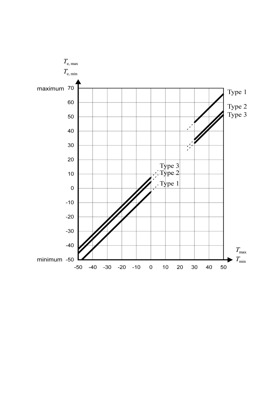
(4) The minimum and maximum uniform bridge temperature components
T
e.min
and
T
e.max
should be determined.
NOTE: The National Annex may specify
T
e.min
and
T
e.max
.
Figure 6.1 below gives
recommended values.
prEN 1991-1-5: 2003 (E)
22
NOTE 1: The values in Figure 6.1 are based on daily temperature ranges of 10
o
C. Such a
range may be considered appropriate for most Member States.
NOTE 2: For steel truss and plate girders the maximum values given for type 1 may be
reduced by 3
o
C.
Figure 6.1: Correlation between minimum/maximum shade air temperature
(T
min
/T
max
) and minimum/maximum uniform bridge temperature component
(T
e.min
/T
e.max
)

prEN 1991-1-5: 2003 (E)
23
6.1.3.2 Shade air temperature
(1)P Characteristic values of minimum and maximum shade air temperatures for the
site location shall be obtained, e.g. from national maps of isotherms.
NOTE: Information (e.g. maps of isotherms) on minimum and maximum shade air
temperatures to be used in a Country may be found in its National Annex.
(2) These characteristic values should represent shade air temperatures for mean
sea level in open country with an annual probability of being exceeded of 0,02. For
other annual probabilities of being exceeded (
p other than 0,02), height above sea
level and local conditions (e.g. frost pockets) the values should be adjusted in
accordance with annex A.
(3) Where an annual probability of being exceeded of 0,02 is deemed inappropriate,
the minimum shade air temperatures and the maximum shade air temperatures
should be modified in accordance with annex A.
6.1.3.3 Range of uniform bridge temperature component
(1)P The values of minimum and maximum uniform bridge temperature components
for restraining forces shall be derived from the minimum (
T
min
) and maximum (
T
max
)
shade air temperatures (see 6.1.3.1(3) and 6.1.3.1(4)).
(2) The initial bridge temperature
T
o
at the time that the structure is restrained may be
taken from annex A for calculating contraction down to the minimum uniform bridge
temperature component and expansion up to the maximum uniform bridge
temperature component.
(3) Thus the characteristic value of the maximum contraction range of the uniform
bridge temperature component,
∆
T
N,con
should be taken as
∆
T
N,con
=
T
0
-
T
e.min
(6.1)
and the characteristic value of the maximum expansion range of the uniform bridge
temperature component,
∆
T
N,exp
should be taken as
∆
T
N,exp
=
T
e .max
-
T
o
(6.2)
NOTE 1: The overall range of the uniform bridge temperature component is
∆
T
N
=
T
e.max
-
T
e.min
NOTE 2: For bearings and expansion joints the National Annex may specify the maximum
expansion range of the uniform bridge temperature component, and the maximum
contraction range of the uniform bridge temperature component, if no other provisions are
required. The recommended values are (
∆
T
N,exp
+ 20)
o
C and (
∆
T
N,con
+ 20)
o
C. If the
temperature at which the bearings and expansion joints are set is specified, then the
recommended values are (
∆
T
N,exp
+ 10)
o
C and (
∆
T
N,con
+ 10)
o
C.

prEN 1991-1-5: 2003 (E)
24
NOTE 3: For the design of bearings and expansion joints, the values of the coefficient of
expansion given in annex C, Table C.1 may be modified if alternative values have been
verified by tests or more detailed studies.
6.1.4
Temperature difference components
(1) Over a prescribed time period heating and cooling of a bridge deck's upper
surface will result in a maximum heating (top surface warmer) and a maximum
cooling (bottom surface warmer) temperature variation.
(2) The vertical temperature difference may produce effects within a structure due to:
–
Restraint of free curvature due to the form of the structure (e.g. portal frame,
continuous beams etc.);
–
Friction at rotational bearings;
–
Non-linear geometric effects (2nd order effects).
(3) In the case of cantilever construction an initial temperature difference may need
to be taken into account at the closure of the cantilever.
NOTE: Values of the initial temperature difference may be specified in the National Annex.
6.1.4.1 Vertical linear component (Approach 1)
(1) The effect of vertical temperature differences should be considered by using an
equivalent linear temperature difference component (see 6.1.2(2))with
∆
T
M,heat
and
∆
T
M,cool
. These values should be applied between the top and the bottom of the bridge
deck.
NOTE: Values of
∆
T
M,heat
and
∆
T
M,cool
to be used in a Country may be found in its National
Annex. Recommended values
for
∆
T
M,heat
and
∆
T
M,cool
are given in Table 6.1.

prEN 1991-1-5: 2003 (E)
25
Table 6.1: Recommended values of linear temperature difference component
for different types of bridge decks for road, foot and railway bridges
Top warmer than bottom
Bottom warmer than top
Type of Deck
∆
T
M,heat
(
o
C)
∆
T
M,cool
(
o
C)
Type 1:
Steel deck
18
13
Type 2:
Composite deck
15
18
Type 3:
Concrete deck:
- concrete box girder
- concrete beam
- concrete slab
10
15
15
5
8
8
NOTE 1: The values given in the table represent upper bound values of the linearly
varying temperature difference component for representative sample of bridge geometries.
NOTE 2: The values given in the table are based on a depth of surfacing of 50 mm for
road and railway bridges. For other depths of surfacing these values should be multiplied
by the factor
k
sur
.
Recommended values for the factor
k
sur
is given in Table 6.2.

prEN 1991-1-5: 2003 (E)
26
Table 6.2: Recommended values of
k
sur
to account for different surfacing
thickness
Road, foot and railway bridges
Type 1
Type 2
Type 3
Surface
Thickness Top warmer
than bottom
Bottom
warmer
than top
Top warmer
than bottom
Bottom
warmer
than top
Top warmer
than bottom
Bottom
warmer
than top
[mm]
k
sur
k
sur
k
sur
k
sur
k
sur
k
sur
unsurfaced
0,7
0,9
0,9
1,0
0,8
1,1
water-
proofed
1)
1,6
0,6
1,1
0,9
1,5
1,0
50
1,0
1,0
1,0
1,0
1,0
1,0
100
0,7
1,2
1,0
1,0
0,7
1,0
150
0,7
1,2
1,0
1,0
0,5
1,0
ballast
(750 mm)
0,6
1,4
0,8
1,2
0,6
1,0
1)
These values represent upper bound values for dark colour
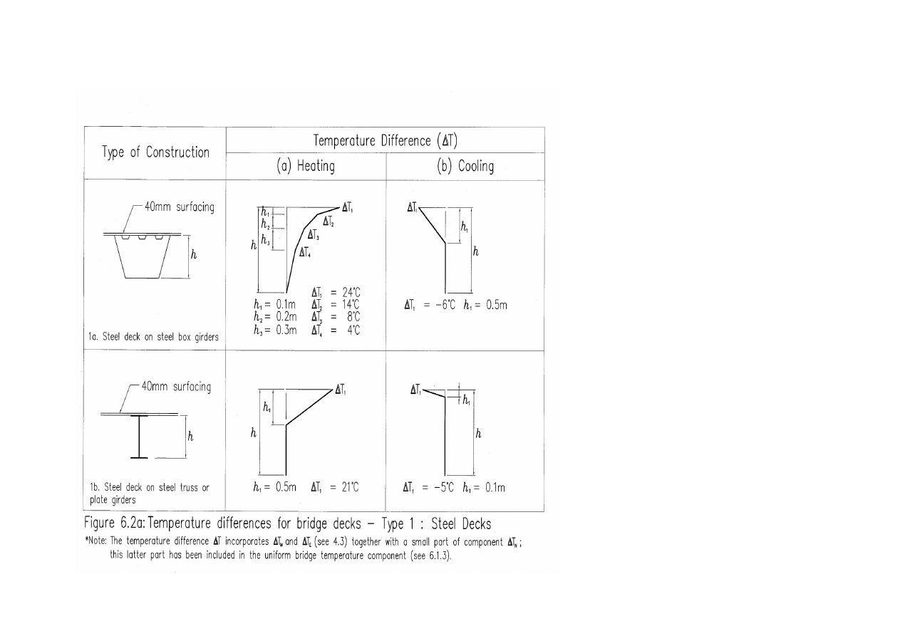
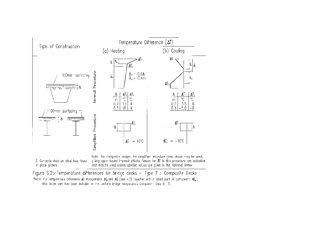
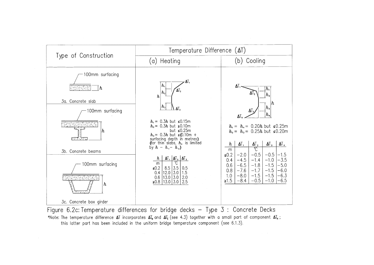
6.1.4.2 Vertical temperature components with non-linear effects (Approach 2)
(1) The effect of the vertical temperature differences should be considered by
including a non-linear temperature difference component (see 6.1.2.2).
NOTE 1: Values of vertical temperature differences for bridge decks to be used in a Country
may be found in its National annex. Recommended values are given in Figures 6.2a - 6.2c.
In these figures “heating” refers to conditions such that solar radiation and other effects
cause a gain in heat through the top surface of the bridge deck. Conversely, “cooling” refers
to conditions such that heat is lost from the top surface of the bridge deck as a result of re-
radiation and other effects.
NOTE 2: The temperature difference
∆
T incorporates
∆
T
M
and
∆
T
E
(see 4(3)) together with a
small part of component
∆
T
N
; this latter part is included in the uniform bridge temperature
component (see 6.1.3).
prEN 1991-1-5: 2003 (E)
27
prEN 1991-1-5: 2003 (E)
28
prEN 1991-1-5: 2003 (E)
29

prEN 1991-1-5: 2003 (E)
30
6.1.4.3 Horizontal components
(1) In general, the temperature difference component need only be considered in the
vertical direction. In particular cases however (for example when the orientation or
configuration of the bridge results in one side being more highly exposed to sunlight
than the other side), a horizontal temperature difference component should be
considered.
NOTE: The National annex may specify numerical values for the temperature difference. If
no other information is available and no indications of higher values exist, 5
o
C may be
recommended as a linear temperature difference between the outer edges of the bridge
independent of the width of the bridge.
6.1.4.4 Temperature difference components within walls of concrete box
girders
(1) Care should be exercised in the design of large concrete box girder bridges
where significant temperature differences can occur between the inner and outer web
walls of such structures.
NOTE: The National annex may specify numerical values for the temperature difference. The
recommended value for a linear temperature difference is 15
0
C.
6.1.5
Simultaneity of uniform and temperature difference components
(1) If it is necessary to take into account both the temperature difference
∆
T
M,heat
(or
∆
T
M,cool
) and the maximum range of uniform bridge temperature component
∆
T
N,exp
(or
∆
T
N,con
) assuming simultaneity (e.g. in case of frame structures) the following
expression may be used (which should be interpreted as load combinations):
∆
T
M,heat
(or
∆
T
M,cool
) +
ω
N
∆
T
N,exp
(or
∆
T
N,con
)
(6.3)
or
ω
M
∆
T
M,heat
(or
∆
T
M,cool
) +
∆
T
N,exp
(or
∆
T
N,con
)
(6.4)
where the most adverse effect should be chosen.
NOTE 1: The National annex may specify numerical values of
ω
N
and
ω
M
. If no other
information is available, the recommended values for
ω
N
and
ω
M
are:
ω
N
=
0,35
ω
M
=
0,75.
NOTE 2: Where both linear and non-linear vertical temperature differences are used (see
6.1.4.2)
∆
T
M
should be replaced by
∆
T which includes
∆
T
M
and
∆
T
E
.

prEN 1991-1-5: 2003 (E)
31
6.1.6
Differences in the uniform temperature component between different
structural elements
(1) In structures where differences in the uniform temperature component between
different element types may cause adverse load effects, these effects should be
taken into account.
NOTE: The National annex may give values for the differences in the uniform temperature
component. Recommended values are:
–
15
o
C between main structural elements (e.g. tie and arch); and
–
10
o
C and 20
o
C for light and dark colour respectively between suspension/stay
cables and deck (or tower).
(2) These effects should be considered in addition to the effects resulting from a
uniform temperature component in all elements, determined from 6.1.3.
6.2
Bridge Piers
6.2.1
Consideration of thermal actions
(1)P Temperature differences between the outer faces of bridge piers, hollow or
solid, shall be considered in the design.
NOTE: The design procedure to be used in a Country may be found in its National annex. If
no procedure is given an equivalent linear temperature difference may be assumed.
(2) Overall temperature effects of piers should be considered, when these can lead to
restraining forces or movements in the surrounding structures.
6.2.2
Temperature differences
(1) For concrete piers (hollow or solid), the linear temperature differences between
opposite outer faces should be taken into account.
NOTE: The National annex may specify values for
linear temperature differences
. In the
absence of detailed information the recommended value is
5
o
C.
(2) For walls the linear temperature differences between the inner and outer faces
should be taken into account.
NOTE 1: The National annex may specify values for
linear temperature differences
. In the
absence of detailed information the recommended value is 1
5
o
C.
NOTE 2: When considering temperature differences for metal columns specialist advice may
need to be obtained.

prEN 1991-1-5: 2003 (E)
32
Section 7
Temperature changes in industrial chimneys, pipelines,
silos, tanks and cooling towers
7.1
General
(1)P Structures which are in contact with gas flow, liquids or material with different
temperatures (e.g. industrial chimneys, pipelines, silos, tanks and cooling towers)
shall be designed where relevant for the following conditions:
–
thermal actions from climatic effects due to the variation of shade air temperature
and solar radiation,
–
temperature distribution for normal and abnormal process conditions,
–
effects arising from interaction between the structure and its contents during
thermal changes (e.g. shrinkage of the structure against stiff solid contents or
expansion of solid contents during heating or cooling).
NOTE 1: Values of the operating process temperature may be obtained from the particular
project.
NOTE 2: For the operating process temperatures of chimneys see EN 13084-1.
NOTE 3: Containment structures may be subjected to thermally induced changes in shape
arising from heating/cooling effects of either the contents or their surrounding external
environment.
NOTE 4: No further guidance on the effect of shrinkage against stiff solid contents is given in
this standard. See EN 1991-4 for this effect in silos.
7.2
Temperature components
7.2.1
Shade air temperature
(1)P Values of minimum and maximum shade air temperatures for the site location
shall be obtained, e.g. from national maps of isotherms.
NOTE: Information (e.g. maps of isotherms) on minimum and maximum shade air
temperatures to be used in a Country may be found in its National annex.
(2) These shade air temperatures should be appropriate to mean sea level in open
country with an annual probability of being exceeded of 0,02. annex A includes
adjustments for other values of probabilities, height above sea level and local
conditions e.g. frost pockets.
(3) For circumstances where an annual probability of being exceeded of 0,02 is
deemed inappropriate, e.g. during execution (see EN1991-1-6 “Actions during

prEN 1991-1-5: 2003 (E)
33
execution”), the values of minimum (or maximum) shade air temperature should be
modified in accordance with annex A.
7.2.2
Flue gas, heated liquids and heated materials temperature
(1) Values of maximum and minimum flue gas, liquids and materials with different
temperatures should be specified for the particular project.
7.2.3
Element temperature
(1) The derivation of values of element temperature will depend on the material
configuration, orientation and location of the element and will be a function of the
maximum and minimum shade air temperature, the external solar radiation, and the
internal operating temperature.
NOTE: General rules for the determination of temperature profiles are given in annex D. See
also 7.5.
7.3
Consideration of temperature components
(1)P Both the uniform temperature component of the temperature distribution (see
Figure 4.1 (a)) and the linearly varying temperature difference component (see
Figure 4.1 (b)) shall be considered for each layer.
(2)P The effect of solar radiation shall be considered in the design.
(3) This effect may be approximated by a step temperature distribution round the
structure’s circumference.
(4)P The uniform temperature component and the linearly varying temperature
difference component due to process temperature shall be considered for each layer.
7.4
Determination of temperature components
(1)P The uniform and linearly varying temperature components shall be determined
taking into account climatic effects and operating conditions.
(2) If specific information on how the element temperature can be correlated with the
solar radiation and shade air temperature is available in order to provide values of
element temperature, such information should be used to provide design values.
(3)P Values of the uniform temperature component from heated gas flow, liquids and
heated materials shall be taken from the project specification. As far as chimneys are
concerned these values shall be obtained from EN 13084-1.
(4)P The linearly varying temperature difference component in the wall or its layers
shall be taken as arising from the difference between the minimum (or maximum)

prEN 1991-1-5: 2003 (E)
34
shade air temperature on the outer face and the value of the liquid or gas
temperature on the inner face, taking into account insulation effects.
NOTE: Temperature profiles may be determined using annex D.
7.5
Values of temperature components (indicative values)
(1) In the absence of any specific information on characteristic values of the element
temperature, the following indicative values may be used.
NOTE: These values may be checked against any available data to ensure that they are
likely to be upper bound values, for the location and the type of element under consideration.
(2) Values of the maximum and minimum uniform temperature component should be
taken as those of the maximum and minimum shade air temperature (see 7.2.1).
(3) For concrete pipelines the linear temperature difference component between the
inner and outer faces of the wall should be considered.
NOTE 1: The National annex may specify the values for the linear temperature difference
component. The recommended value is 15
o
C.
NOTE 2: For chimneys see EN 13084-1.
(4) For concrete pipelines a stepped temperature component round the
circumference (causing both overall and local thermal effects) should be considered
on the basis that one quadrant of its circumference has a mean temperature higher
than that of the remainder of the circumference.
NOTE: The value of the difference of temperature may be given in the National annex. The
recommended value is 15
o
C.
(5) When considering steel pipelines, the linear temperature difference component
and stepped temperature component round the structure’s circumference should be
calculated taking into account the operating conditions as set down in the particular
project.
NOTE: The rules for steel chimneys are given in EN 13084-1.
7.6
Simultaneity of temperature components
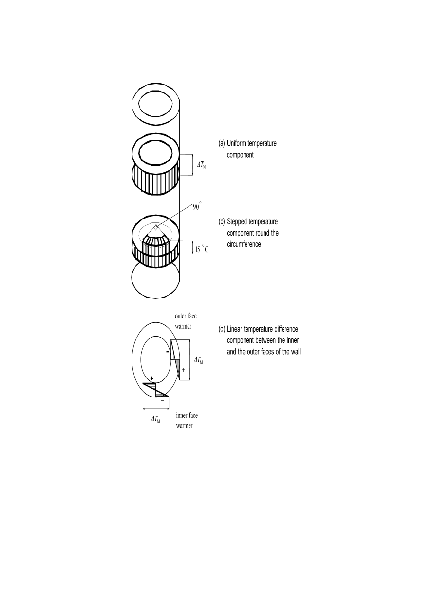
(1) When considering thermal actions due to climatic effects only, the following
components take account of simultaneity:
a) uniform temperature component (see 7.5 (2) and Figure 7.1 (a));
b) stepped temperature component (see 7.5 (4) and Figure 7.1 (b));

prEN 1991-1-5: 2003 (E)
35
c) the linear temperature difference component between the inner and the outer
faces of the wall (see 7.5 (3) and Figure 7.1 (c)).
(2) When considering a combination of thermal actions due to climatic effects with
those due to process effects (heated gas flow, liquids or heated materials) the
following components should be combined:
–
uniform temperature component (see 7.4 (3));
–
linear temperature difference component (see 7.4 (4));
–
stepped component (see 7.5 (4)).
(3) The stepped temperature component should be considered to act simultaneously
with wind.
prEN 1991-1-5: 2003 (E)
36
Key
a
Uniform temperature component
b
Stepped temperature component round the circumference
c
Linear temperature difference component between the inner and the outer faces
of the wall
1 Outer face warmer
2 Inner
face
warmer
Figure 7.1: Relevant temperature components for pipelines, silos, tanks and
cooling towers

prEN 1991-1-5: 2003 (E)
37
Annex A
(Normative)
Isotherms of national minimum and maximum shade air
temperatures
A.1
General
(1) The values of both annual minimum and annual maximum shade air temperature
represent values with an annual probability of being exceeded of 0,02.
NOTE 1: Information (e.g. maps or tables of isotherms) on both annual minimum and annual
maximum shade air temperature to be used in a Country may be found in its National annex.
NOTE 2: These values may need to be adjusted for height above sea level. The adjustment
procedure is given in the National annex. If no information is available the values of shade air
temperature may be adjusted for height above sea level by subtracting 0,5
o
C per 100 m
height for minimum shade air temperatures and 1,0
o
C per 100 m height for maximum shade
air temperatures.
(2) In locations where the minimum values diverge from the values given, such as
frost pockets and sheltered low lying areas where the minimum may be substantially
lower, or in large conurbations and coastal sites, where the minimum may be higher
than that indicated in the relevant figures, these divergences should be taken into
consideration using local meteorological data.
(3) The initial temperature
T
0
should be taken as the temperature of a structural
element at the relevant stage of its restraint (completion). If it is not predictable the
average temperature during the construction period should be taken.
NOTE: The value of T
0
may be specified in the National annex. If no information is available
T
0
may be taken as 10
o
C.
A.2
Maximum and minimum shade air temperature values with an annual
probability of being exceeded
p other than 0,02
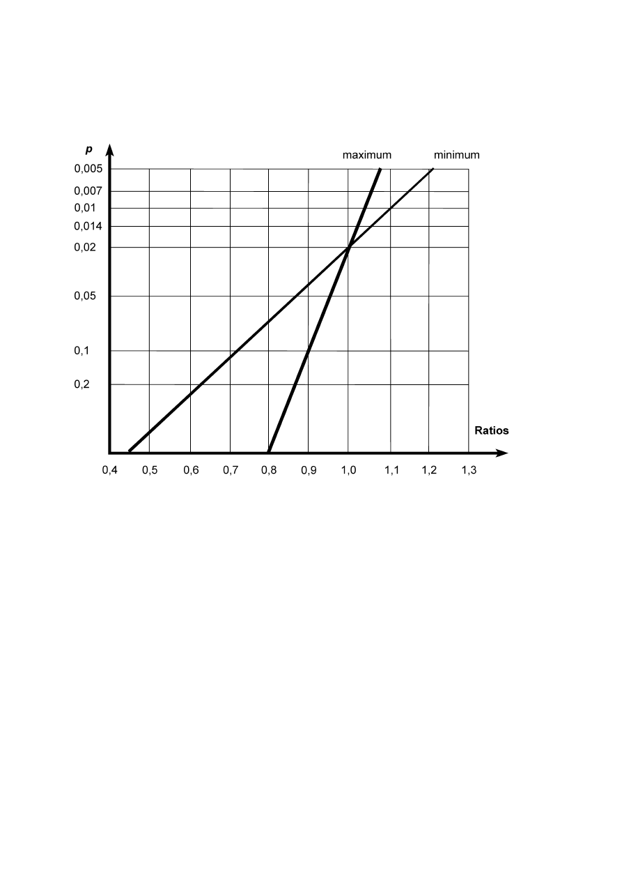
(1) If the value of maximum (or minimum) shade air temperature,
T
max,p
(
T
min,p
), is
based on an annual probability of being exceeded
p other than 0,02, the ratio
T
max,p
/
T
max
(
T
min,p
/
T
min
) may be determined from Figure A.1.
(2) In general
T
max,p
(or
T
min,p
) may be derived from the following expressions based
on a type I extreme value distribution:
- for maximum:
T
max,p
=
T
max
{
k
1
-
k
2
ln [ - ln (1-
p) ] }
(A.1)
- for minimum:
T
min,p
=
T
min
{
k
3
+
k
4
ln [ - ln (1-
p) ] }
(A.2)

prEN 1991-1-5: 2003 (E)
38
where:
T
max
(
T
min
)
is the value of maximum (minimum) shade air temperature with
an annual probability of being exceeded of 0,02;
k
1
= (
u,c) / { (u,c) + 3,902 }
(A.3)
k
2
= 1 / { (
u,c) + 3,902 }
(A.4)
where:
u,c
are the mode and scale parameters of annual maximum shade air
temperature distribution.
k
3
= (
u,c) / { (u,c) - 3,902 }
(A.5)
k
4
= 1 / { (
uc) - 3,902 }
(A.6)
The parameters
u and c are dependent on the mean value m and the standard
deviation
σ
of type I extreme value distribution:
for maximum
u = m - 0,57722 / c
c = 1,2825 /
σ
(A.7)
for minimum
u = m + 0,57722 / c
c = 1,2825 /
σ
(A.8)
The ratios
T
max,p
/
T
max
and
T
min,p
/
T
min
respectively may then be taken from Figure A.1.
NOTE1: The National annex may specify the values of the coefficients
k
1
,
k
2
,
k
3
and
k
4
based
on the values of parameters
u and c. If no other information is available the following values
are recommended:
k
1
= 0,781;
k
2
= 0,056;
k
3
= 0,393;
k
4
= - 0,156.
NOTE 2: Expression (A.2) and Figure A.1 can only be used if
T
min
is negative.
prEN 1991-1-5: 2003 (E)
39
Figure A.1: Ratios
T
max,p
/
T
max
and
T
min,p
/
T
min

prEN 1991-1-5: 2003 (E)
40
Annex B
(Normative)
Temperature differences for various surfacing depths
(1) Temperature difference profiles given in Figures 6.2a - 6.2c are valid for 40 mm
surfacing depths for deck type 1 and 100 mm surfacing depths for types 2 and 3.
NOTE: The National annex may give values for other depths. Recommended values are
given in the following tables:
–
Table B.1 for deck type 1;
–
Table B.2 for deck type 2;
–
Table B.3 for deck type 3.
Table B.1 – Recommended values of
∆
T for deck type 1
Temperature difference
Heating
Cooling
Surfacing
thickness
∆
T
1
∆
T
2
∆
T
3
∆
T
4
∆
T
1
mm
o
C
o
C
o
C
o
C
o
C
unsurfaced
20
40
30
27
24
16
15
14
6
9
8
3
5
4
8
6
6

prEN 1991-1-5: 2003 (E)
41
Table B.2 – Recommended values of
∆
T for deck type 2
Temperature difference
Heating
Cooling
Depth of
slab (
h)
Surfacing
thickness
∆
T
1
∆
T
1
m
mm
o
C
o
C
0,2
0,3
unsurfaced
waterproofed
1)
50
100
150
200
unsurfaced
waterproofed
1)
50
100
150
200
16,5
23,0
18,0
13,0
10,5
8,5
18,5
26,5
20,5
16,0
12,5
10,0
5,9
5,9
4,4
3,5
2,3
1,6
9,0
9,0
6,8
5,0
3,7
2,7
1)
These values represent upper bound values for dark colour

prEN 1991-1-5: 2003 (E)
42
Table B.3 – Recommended values of
∆
T for deck type 3
Temperature difference
Heating
Cooling
Depth of
slab (
h)
Surfacing
thickness
∆
T
1
∆
T
2
∆
T
3
∆
T
1
∆
T
2
∆
T
3
∆
T
4
m
mm
o
C
o
C
o
C
o
C
o
C
o
C
o
C
0,2
unsurfaced
waterproofed
1)
50
100
150
200
12,0
19,5
13,2
8,5
5,6
3,7
5,0
8,5
4,9
3,5
2,5
2,0
0,1
0,0
0,3
0,5
0,2
0,5
4,7
4,7
3,1
2,0
1,1
0,5
1,7
1,7
1,0
0,5
0,3
0,2
0,0
0,0
0,2
0,5
0,7
1,0
0,7
0,7
1,2
1,5
1,7
1,8
0,4
unsurfaced
waterproofed
1)
50
100
150
200
15,2
23,6
17,2
12,0
8,5
6,2
4,4
6,5
4,6
3,0
2,0
1,3
1,2
1,0
1,4
1,5
1,2
1,0
9,0
9,0
6,4
4,5
3,2
2,2
3,5
3,5
2,3
1,4
0,9
0,5
0,4
0,4
0,6
1,0
1,4
1,9
2,9
2,9
3,2
3,5
3,8
4,0
0,6
unsurfaced
waterproofed
1)
50
100
150
200
15,2
23,6
17,6
13,0
9,7
7,2
4,0
6,0
4,0
3,0
2,2
1,5
1,4
1,4
1,8
2,0
1,7
1,5
11,8
11,8
8,7
6,5
4,9
3,6
4,0
4,0
2,7
1,8
1,1
0,6
0,9
0,9
1,2
1,5
1,7
1,9
4,6
4,6
4,9
5,0
5,1
5,1
0,8
unsurfaced
waterproofed
1)
50
100
150
200
15,4
23,6
17,8
13,5
10,0
7,5
4,0
5,0
4,0
3,0
2,5
2,1
2,0
1,4
2,1
2,5
2,0
1,5
12,8
12,8
9,8
7,6
5,8
4,5
3,3
3,3
2,4
1,7
1,3
1,0
0,9
0,9
1,2
1,5
1,7
1,9
5,6
5,6
5,8
6,0
6,2
6,0
1,0
unsurfaced
waterproofed
1)
50
100
150
200
15,4
23,6
17,8
13,5
10,0
7,5
4,0
5,0
4,0
3,0
2,5
2,1
2,0
1,4
2,1
2,5
2,0
1,5
13,4
13,4
10,3
8,0
6,2
4,3
3,0
3,0
2,1
1,5
1,1
0,9
0,9
0,9
1,2
1,5
1,7
1,9
6,4
6,4
6,3
6,3
6,2
5,8
1,5
unsurfaced
waterproofed
1)
50
100
150
200
15,4
23,6
17,8
13,5
10,0
7,5
4,5
5,0
4,0
3,0
2,5
2,1
2,0
1,4
2,1
2,5
2,0
1,5
13,7
13,7
10,6
8,4
6,5
5,0
1,0
1,0
0,7
0,5
0,4
0,3
0,6
0,6
0,8
1,0
1,1
1,2
6,7
6,7
6,6
6,5
6,2
5,6
1)
These values represent upper bound values for dark colour

prEN 1991-1-5: 2003 (E)
43
Annex C
(Informative)
Coefficients of linear expansion
(1) For the determination of action effects due to temperature components, Table C.1
gives values for the coefficient of linear expansion for a selection of commonly used
materials.

prEN 1991-1-5: 2003 (E)
44
Table C.1: Coefficients of linear expansion
Material
α
T
(x10
-6
/°C)
Aluminium, aluminium alloy
24
Stainless steel
16
Structural steel, wrought or cast iron
12 (see Note 6)
Concrete except as under
10
Concrete, lightweight aggregate
7
Masonry
6-10 (see Notes)
Glass
(see Note 4)
Timber, along grain
5
Timber, across grain
30-70 (see Notes)
NOTE 1: For other materials special advice should be sought.
NOTE 2: The values given should be used for the derivation of thermal actions,
unless other values can be verified by tests or more detailed studies.
NOTE 3: Values for masonry will vary depending on the type of brickwork; values
for timber across the grain can vary considerably according to the type of timber.
NOTE 4: For more detailed information see:
EN 572-1:
Glass in Building - Basic soda lime silicate glass - Part 1:
Definitions and general physical and mechanical properties;
prEN 1748-1-1:
Glass in Building - Special basic products - Part 1-1:
Borosilicate glass – Definition and description;
prEN 1748-2-1:
Glass in Building - Special basic products - Part 1-1 : Glass
ceramics – Definition and description;
prEN 14178-1:
Glass in Building – Basic alkaline earth silicate glass products
– Part 1: Float glass
NOTE 5: For some materials such as masonry and timber other parameters (e.g.
moisture content) also need to be considered. See EN 1995 -EN 1996.
NOTE 6 : For composite structures the coefficient of linear expansion of the steel
component may be taken as equal to 10x10
-6
/
o
C to neglect restraining effects from
different
α
T
-values.

prEN 1991-1-5: 2003 (E)
45
Annex D
(Informative)
Temperature profiles in buildings and other construction works
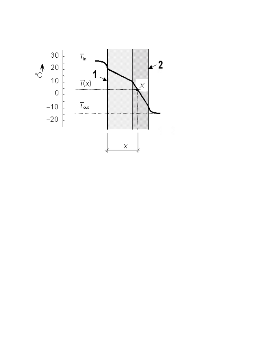
(1) Temperature profiles may be determined using the thermal transmission theory.
In the case of a simple sandwich element (e.g. slab, wall, shell) under the
assumption that local thermal bridges do not exist a temperature
T(x) at a distance x
from the inner surface of the cross section may be determined assuming steady
thermal state as
)
(
)
(
)
(
out
in
tot
in
T
T
R
x
R
T
x
T
−
−
=
(D.1)
where:
T
in
is the air temperature of the inner environment
T
out
is the temperature of the outer environment
R
tot
is the total thermal resistance of the element including resistance of
both surfaces
R(x)
is the thermal resistance at the inner surface and of the element from
the inner surface up to the point
x (see Figure D.1).
(2) The resistance values
R
tot
, and
R(x) [m
2
K/W] may be determined using the
coefficient of heat transfer and coefficients of thermal conductivity given in EN ISO
6946 (1996) and EN ISO 13370 (1998):
out
in
tot
R
h
R
R
i
i
i
+
+
=
∑
λ
(D.2)
where:
R
in
is the thermal resistance at the inner surface [m
2
K/W]
,
R
out
is the thermal resistance at the outer surface [m
2
K/W],
λ
i
is the thermal conductivity and
h
i
[m] is the thickness of the layer
i,
[W/(mK)]
∑
+
=
i
i
i
h
R
x
R
λ
in
)
(
(D.3)
where layers (or part of a layer) from the inner surface up to point
x (see Figure D.1)
are considered only.
NOTE: In buildings the thermal resistance
R
in
= 0,10 to 0,17 [m
2
K/W] (depending on the
orientation of the heat flow), and
R
out
= 0,04 (for all orientations). The thermal conductivity
λ
i
for concrete (of volume weight from 21 to 25 kN/m
3
) varies from
λ
i
= 1,16 to 1,71 [W/(mK)].
prEN 1991-1-5: 2003 (E)
46
Key
1 Inner
surface
2
Outer surface
Figure D.1: Thermal profile of a two-layer element.

prEN 1991-1-5: 2003 (E)
47
Bibliography
EN 1991-2
Eurocode 1: Actions on structures - Part 2: Traffic loads on bridges
EN 1991-4 Eurocode 1: Basis of design and actions on structures - Part 4: Actions in
silos and tanks
Wyszukiwarka
Podobne podstrony:
Eurocode 1 Part 1,3 prEN 1991 1 3 2003
Eurocode 1 Part 1,7 prEN 1991 1 7 2003
Eurocode 1 Part 1,6 prEN 1991 1 6 2004
Eurocode 1 Part 2 prEN 1991 2 2002
Eurocode 1 Part 1,2 prEN 1991 1 2 2002
Eurocode 1 Part 1,1 prEN 1991 1 1 2001
Eurocode 1 Part 3 prEN 1991 3 2002
Eurocode 8 Part 4 prEN 1998 4 2003 (12 2003)
Eurocode 1 Part 1,4 prEN 1991 1 4 2004
Eurocode 3 Part 1,9 PrEN 1993 1 9 2003
Eurocode 3 Part 1,8 prEN 1993 1 8 2003
Eurocode 1 Part 1,6 prEN 1991 1 6 2004
Eurocode 3 Part 1,9 PrEN 1993 1 9 2003
Eurocode 3 Part 1,8 prEN 1993 1 8 2003
Eurocode 8 Part 1 prEN 1998 1 (12 2003)
Eurocode 8 Part 5 prEn 1998 5 (12 2003)
Eurocode 8 Part 3 prEN 1998 3 (07 2003)
Eurocode 8 Part 1 prEN 1998 1 (12 2003)
więcej podobnych podstron