
EUROPEAN STANDARD
NORME EUROPÉENNE
EUROPÄISCHE NORM
FINAL DRAFT
prEN 1993-1-8
December 2003
ICS
Will supersede ENV 1993-1-1:1992
English version
Eurocode 3: Design of steel structures - Part 1-8: Design of
joints
Eurocode 3: Calcul des structures en acier - Partie 1-8:
Calcul des assemblages
Eurocode 3: Bemessung und Konstruktion von Stahlbauten
- Teil 1-8: Bemessung von Anschlüssen
This draft European Standard is submitted to CEN members for formal vote. It has been drawn up by the Technical Committee CEN/TC
250.
If this draft becomes a European Standard, CEN members are bound to comply with the CEN/CENELEC Internal Regulations which
stipulate the conditions for giving this European Standard the status of a national standard without any alteration.
This draft European Standard was established by CEN in three official versions (English, French, German). A version in any other
language made by translation under the responsibility of a CEN member into its own language and notified to the Management Centre has
the same status as the official versions.
CEN members are the national standards bodies of Austria, Belgium, Czech Republic, Denmark, Finland, France, Germany, Greece,
Hungary, Iceland, Ireland, Italy, Luxembourg, Malta, Netherlands, Norway, Portugal, Slovakia, Spain, Sweden, Switzerland and United
Kingdom.
Warning : This document is not a European Standard. It is distributed for review and comments. It is subject to change without notice and
shall not be referred to as a European Standard.
EUROPEAN COMMITTEE FOR STANDARDIZATION
C O M I T É E U R O P É E N D E N O R M A L I S A T I O N
E U R O P Ä I S C H E S K O M I T E E F Ü R N O R M U N G
Management Centre: rue de Stassart, 36 B-1050 Brussels
© 2003 CEN
All rights of exploitation in any form and by any means reserved
worldwide for CEN national Members.
Ref. No. prEN 1993-1-8:2003 E

SU(1(
&RQWHQW
3DJH
,QWURGXFWLRQ
1.1
Scope
6
1.2
Distinction between Principles and Application Rules
6
1.3
Definitions
6
1.4
Symbols
7
%DVLVRIGHVLJQ
2.1
Assumptions
13
2.2
General requirements
13
2.3
Applied forces and moments
13
2.4
Resistance of joints
13
2.5
Design assumptions
14
2.6
Joints loaded in shear subject to impact, vibration and/or load reversal
14
2.7
Eccentricity at intersections
14
2.8
References
15
&RQQHFWLRQVPDGHZLWKEROWVULYHWVRUSLQV
3.1
Bolts, nuts and washers
18
3.1.1
General
18
3.1.2
Preloaded bolts
18
3.2
Rivets
18
3.3
Anchor bolts
18
3.4
Categories of bolted connections
18
3.4.1
Shear connections
18
3.4.2
Tension connections
19
3.5
Positioning of holes for bolts and rivets
20
3.6
Design resistance of individual fasteners
21
3.6.1
Bolts and rivets
21
3.6.2
Injection bolts
25
3.7
Group of fasteners
26
3.8
Long joints
26
3.9
Slip-resistant connections using 8.8 or 10.9 bolts
27
3.9.1
Design Slip resistance
27
3.9.2
Combined tension and shear
28
3.9.3
Hybrid connections
28
3.10
Deductions for fastener holes
28
3.10.1
General
28
3.10.2
Design for block tearing
29
3.10.3
Angles connected by one leg and other unsymmetrically connected members in tension
30
3.10.4
Lug angles
31
3.11
Prying forces
31
3.12
Distribution of forces between fasteners at the ultimate limit state
31
3.13
Connections made with pins
32
3.13.1
General
32
3.13.2
Design of pins
32
:HOGHGFRQQHFWLRQV
4.1
General
35
4.2
Welding consumables
35
4.3
Geometry and dimensions
35
4.3.1
Type of weld
35
4.3.2
Fillet welds
35
4.3.3
Fillet welds all round
36
4.3.4
Butt welds
36
4.3.5
Plug welds
37
4.3.6
Flare groove welds
38

SU(1(
4.4
Welds with packings
38
4.5
Design resistance of a fillet weld
38
4.5.1
Length of welds
38
4.5.2
Effective throat thickness
38
4.5.3
Design Resistance of fillet welds
39
4.6
Design resistance of fillet welds all round
41
4.7
Design resistance of butt welds
41
4.7.1
Full penetration butt welds
41
4.7.2
Partial penetration butt welds
41
4.7.3
T-butt joints
41
4.8
Design resistance of plug welds
42
4.9
Distribution of forces
42
4.10
Connections to unstiffened flanges
43
4.11
Long joints
44
4.12
Eccentrically loaded single fillet or single-sided partial penetration butt welds
44
4.13
Angles connected by one leg
45
4.14
Welding in cold-formed zones
45
$QDO\VLVFODVVLILFDWLRQDQGPRGHOOLQJ
5.1
Global analysis
47
5.1.1
General
47
5.1.2
Elastic global analysis
47
5.1.3
Rigid-plastic global analysis
48
5.1.4
Elastic- plastic global analysis
48
5.1.5
Global analysis of lattice girders
49
5.2
Classification of joints
51
5.2.1
General
51
5.2.2
Classification by stiffness
51
5.2.3
Classification by strength
52
5.3
Modelling of beam-to-column joints
53
6WUXFWXUDOMRLQWVFRQQHFWLQJ+RU,VHFWLRQV
6.1
General
57
6.1.1
Basis
57
6.1.2
Structural properties
57
6.1.3
Basic components of a joint
58
6.2
Design Resistance
62
6.2.1
Internal forces
62
6.2.2
Shear forces
62
6.2.3
Bending moments
63
6.2.4
Equivalent T-stub in tension
64
6.2.5
Equivalent T-stub in compression
67
6.2.6
Design Resistance of basic components
68
6.2.7
Design Moment resistance of beam-to-column joints and splices
81
6.2.8
Design Resistance of column bases with base plates
86
6.3
Rotational stiffness
89
6.3.1
Basic model
89
6.3.2
Stiffness coefficients for basic joint components
91
6.3.3
End-plate connections with two or more bolt-rows in tension
94
6.3.4
Column bases
95
6.4
Rotation capacity
96
6.4.1
General
96
6.4.2
Bolted joints
97
6.4.3
Welded Joints
97

SU(1(
+ROORZVHFWLRQMRLQWV
7.1
General
98
7.1.1
Scope
98
7.1.2
Field of application
98
7.2
Design
100
7.2.1
General
100
7.2.2
Failure modes for hollow section connections
100
7.3
Welds
104
7.3.1
Design resistance
104
7.4
Welded joints between CHS members
105
7.4.1
General
105
7.4.2
Uniplanar joints
105
7.4.3
Multiplanar joints
112
7.5
Welded joints between CHS or RHS brace members and RHS chord members
113
7.5.1
General
113
7.5.2
Uniplanar joints
114
7.5.3
Multiplanar joints
125
7.6
Welded joints between CHS or RHS brace members and I or H section chords
126
7.7
Welded joints between CHS or RHS brace members and channel section chord members
129

SU(1(
)RUHZRUG
This document (prEN 1993-1-8: 2003) has been prepared by Technical Committee CEN/TC 250 "Structural
Eurocodes", the secretariat of which is held be BSI.
This document is currently submitted to the Formal Vote.
This document will supersede ENV 1993-1-1.
1DWLRQDO$QQH[IRU(1
This standard gives alternative procedures, values and recommendations with notes indicating where national
choices may have to be made. The National Standard implementing EN 1993-1-8 should have a National
Annex containing all Nationally Determined Parameters for the design of steel structures to be constructed in
the relevant country.
National choice is allowed in EN 1993-1-8 through:
–
2.2(2)
–
2.8 (Group 6: Rivets)
–
3.4.2(3)
–
6.2.7.2(9)
SU(1(
,QWURGXFWLRQ
6FRSH
(1)
This part of EN 1993 gives design methods for the design of joints subject to predominantly static
loading using steel grades S235, S275, S355 and S460.
'LVWLQFWLRQEHWZHHQ3ULQFLSOHVDQG$SSOLFDWLRQ5XOHV
(1)
The rules in EN 1990 clause 1.4 apply.
7HUPVDQGGHILQLWLRQV
(1)
The following terms and definitions apply:
–
EDVLFFRPSRQHQW(of a joint): Part of a joint that makes a contribution to one or more of its structural
properties.
–
FRQQHFWLRQ: Location at which two or more elements meet. For design purposes it is the assembly of
the basic components required to represent the behaviour during the transfer of the relevant internal
forces and moments at the connection.
–
FRQQHFWHGPHPEHU: Any member that is joined to a supporting member or element.
–
MRLQW: Zone where two or more members are interconnected. For design purposes it is the assembly of
all the basic components required to represent the behaviour during the transfer of the relevant internal
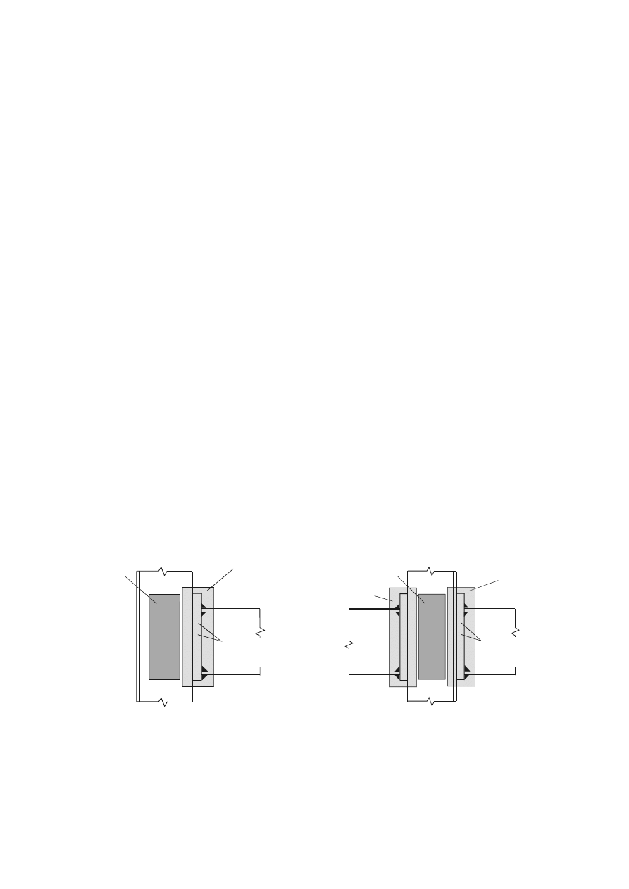
forces and moments between the connected members. A beam-to-column joint consists of a web panel
and either one connection (single sided joint configuration) or two connections (double sided joint
configuration), see Figure 1.1.
–
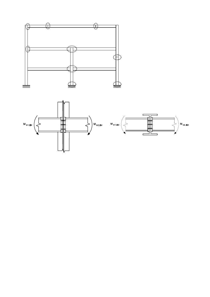
MRLQWFRQILJXUDWLRQ: Type or layout of the joint or joints in a zone within which the axes of two or
more inter-connected members intersect, see Figure 1.2.
–
URWDWLRQDOFDSDFLW\: The angle through which the joint can rotate without failing.
–
URWDWLRQDOVWLIIQHVV: The moment required to produce unit rotation in a joint.
–
VWUXFWXUDO SURSHUWLHV (of a joint): Resistance to internal forces and moments in the connected
members, rotational stiffness and rotation capacity.
–
XQLSODQDUMRLQW: In a lattice structure a uniplanar joint connects members that are situated in a single
plane.
Joint
= web panel in shear + connection
Left joint = web panel in shear + left connection
Right joint = web panel in shear + right connection
a) Single-sided joint configuration
b) Double-sided joint configuration
ZHESDQHOLQVKHDU
FRQQHFWLRQ
FRPSRQHQWVHJEROWVHQGSODWH
)LJXUH3DUWVRIDEHDPWRFROXPQMRLQWFRQILJXUDWLRQ
SU(1(
1
1
2
5
4
5
2
3
3
6LQJOHVLGHGEHDPWRFROXPQMRLQW
FRQILJXUDWLRQ
'RXEOHVLGHGEHDPWRFROXPQ
MRLQWFRQILJXUDWLRQ
%HDPVSOLFH
&ROXPQVSOLFH
&ROXPQEDVH
a) Major-axis joint configurations
Double-sided
beam-to-column
joint
configuration
Double-sided
beam-to-beam
joint
configuration
b) Minor-axis joint configurations (to be used only for balanced moments
0
b1,Ed
=
0
b2,Ed
)
)LJXUH-RLQWFRQILJXUDWLRQV
6\PEROV
(1)
The following symbols are used in this Standard:
d
is
the nominal bolt diameter, the diameter of the pin or the diameter of the fastener;
d
0
is
the hole diameter for a bolt, a rivet or a pin ;
d
o,t
is
the hole size for the tension face, generally the hole diameter, but for horizontally slotted holes
the slot length should be used;
d
o,v
is
the hole size for the shear face, generally the hole diameter, but for vertically slotted holes the slot
length should be used;
d
c
is
the clear depth of the column web;
d
m
is
the mean of the across points and across flats dimensions of the bolt head or the nut, whichever is
smaller;
f
H,Rd
is
the design value of the Hertz pressure;
f
ur
is
the specified ultimate tensile strength of the rivet;

SU(1(
e
1
is
the end distance from the centre of a fastener hole to the adjacent end of any part, measured in the
direction of load transfer, see Figure 3.1;
e
2
is
the edge distance from the centre of a fastener hole to the adjacent edge of any part, measured at
right angles to the direction of load transfer, see Figure 3.1;
e
3
is
the distance from the axis of a slotted hole to the adjacent end or edge of any part, see Figure 3.1;
e
4
is
the distance from the centre of the end radius of a slotted hole to the adjacent end or edge of any
part, see Figure 3.1;
eff
is
the effective length of fillet weld;
n
is
the number of the friction surfaces or the number of fastener holes on the shear face;
p
1
is
the spacing between centres of fasteners in a line in the direction of load transfer, see Figure 3.1;
p
1,0
is the spacing between centres of fasteners in an outer line in the direction of load transfer, see
Figure 3.1;
p
1,i
is the spacing between centres of fasteners in an inner line in the direction of load transfer, see
Figure 3.1;
p
2
is the spacing measured perpendicular to the load transfer direction between adjacent lines of
fasteners, see Figure 3.1;
r
is
the bolt row number;
127(In a bolted connection with more than one bolt-row in tension, the bolt-rows are numbered
starting from the bolt-row furthest from the centre of compression.
V
s
is
the length of stiff bearing.
W
a
is
the thickness of the angle cleat.
W
fc
is
the thickness of the column flange;
W
p
is
the thickness of the plate under the bolt or the nut;
W
w
is
the thickness of the web or bracket;
W
wc
is
the thickness of the column web;
A
is
the gross cross-section area of bolt;
A
0
is
the area of the rivet hole;
A
vc
is
the shear area of the column, see EN 1993-1-1;
A
s
is
the tensile stress area of the bolt or of the anchor bolt;
A
v,eff
is
the effective shear area;
B
p,Rd
is
the design punching shear resistance of the bolt head and the nut
E
is
the elastic modulus;
F
p,Cd
is
the design preload force;
F
t,Ed
is
the design tensile force per bolt for the ultimate limit state;
F
t,Rd
is
the design tension resistance per bolt;
F
T,Rd
is
the tension resistance of an equivalent T-stub flange;
F
v,Rd
is
the design shear resistance per bolt;
F
b,Rd
is
the design bearing resistance per bolt;
F
s,Rd,ser
is the design slip resistance per bolt at the serviceability limit state;
F
s,Rd
is
the design slip resistance per bolt at the ultimate limit state;
F
v,Ed,ser
is the design shear force per bolt for the serviceability limit state;
F
v,Ed
is
the design shear force per bolt for the ultimate limit state;
M
j,Rd
is
the design moment resistance of a joint;
SU(1(
S
j
is
the rotational stiffness of a joint;
S
j,ini
is
the initial rotational stiffness of a joint;
V
wp,Rd
is
the plastic shear resistance of a column web panel;
z is
the
lever
arm;
µ
is
the slip factor;
φ
is
the rotation of a joint.
(2)
The following standard abbreviations are used in section 7:
CHS for “circular hollow section”;
RHS for “rectangular hollow section”, which in this context includes square hollow sections.
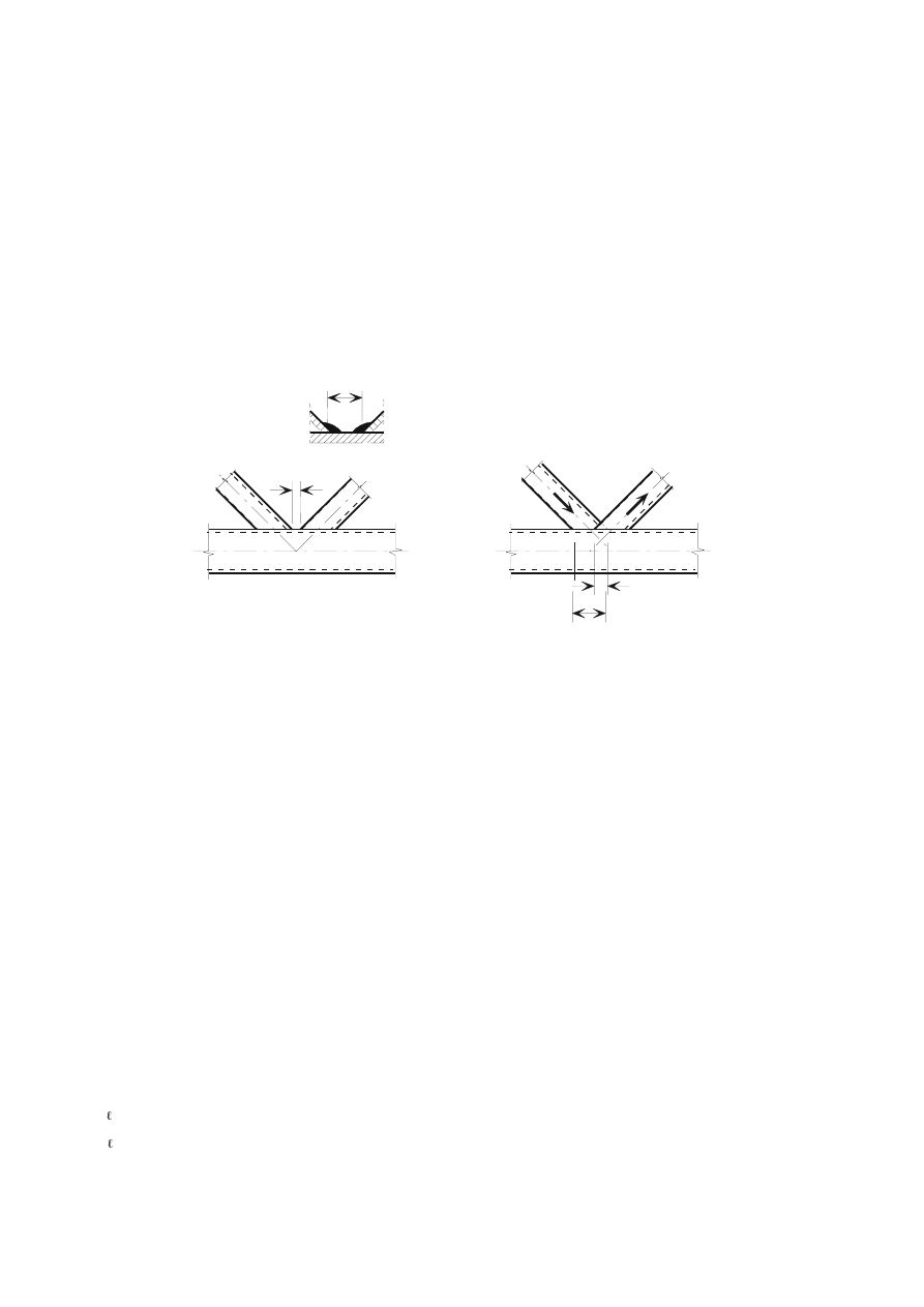
gap g
overlap
λ
ov
= (q/p) x 100 %
g
q
p
g
(a) Definition of gap
(b) Definition of overlap
)LJXUH*DSDQGRYHUODSMRLQWV
(3)
The following symbols are used in section 7:
$
i
is
the cross-sectional area of member
L(L = 0, 1, 2 or 3);
$
v
is
the shear area of the chord;
$
v,eff
is
the effective shear area of the chord;
/
is
the system length of a member;
0
ip,i,Rd
is
the design value of the resistance of the joint, expressed in terms of the in-plane internal moment
in member
L (L = 0, 1, 2 or 3);
0
ip,i,Ed
is the design value of the in-plane internal moment in member
L (L = 0, 1, 2 or 3);
0
op,i,Rd
is the design value of the resistance of the joint, expressed in terms of the out-of-plane internal
moment in member
L (L = 0, 1, 2 or 3);
0
op,i,Ed
is the design value of the out-of-plane internal moment in member
L (L = 0, 1, 2 or 3);
1
i,Rd
is the design value of the resistance of the joint, expressed in terms of the internal axial force in
member
L (L = 0, 1, 2 or 3);
1
i,Ed
is
the design value of the internal axial force in member
L (L= 0, 1, 2 or 3);
:
e
L
is
the elastic section modulus of member
L (L = 0, 1, 2 or 3);
:
p
L
is
the plastic section modulus of member
L (L = 0, 1, 2 or 3);
E
i
is
the overall out-of-plane width of RHS member
L (L = 0, 1, 2 or 3);
E
eff
is
the effective width for a brace member to chord connection;
SU(1(
E
e,ov
is
the effective width for an overlapping brace to overlapped brace connection;
E
e,p
is
the effective width for punching shear;
E
p
is
the width of a plate;
E
w
is
the effective width for the web of the chord;
G
i
is
the overall diameter of CHS member
L (L = 0, 1, 2 or 3);
G
w
is
the depth of the web of an I or H section chord member;
H
is
the eccentricity of a joint;
I
b
is
the buckling strength of the chord side wall;
I
yi
is
the yield strength of member
L (L= 0, 1, 2 or 3);
I
y0
is
the yield strength of a chord member;
J
is
the gap between the brace members in a K or N joint (negative values of
J represent an overlap
T
); the gap
J is measured along the length of the connecting face of the chord, between the toes
of the adjacent brace members, see Figure 1.3(a);
K
i
is
the overall in-plane depth of the cross-section of member
L (L = 0, 1, 2 or 3);
N
is
a factor defined in the relevant table, with subscript g, m, n or p
;
is
the buckling length of a member;
S
is the length of the projected contact area of the overlapping brace member onto the face of the
chord, in the absence of the overlapped brace member, see Figure 1.3(b);
T
is
the length of overlap, measured at the face of the chord, between the brace members in a K or N
joint, see Figure 1.3(b);
U
is
the root radius of an I or H section or the corner radius of a rectangular hollow section;
W
f
is
the flange thickness of an I or H section;
W
i
is
the wall thickness of member
L (L = 0, 1, 2 or 3);
W
p
is
the thickness of a plate;
W
w
is
the web thickness of an I or H section;
is
a factor defined in the relevant table;
i
is
the included angle between brace member
L and the chord (L = 1, 2 or 3);
is
a factor defined where it occurs;
is a factor defined in the relevant table;
is
the angle between the planes in a multiplanar joint.
(4)
The integer subscripts used in section 7 are defined as follows:
L
is
an integer subscript used to designate a member of a joint,
L= 0 denoting a chord and L = 1, 2 or
3 the brace members. In joints with two brace members,
L = 1 normally denotes the
compression brace and
L= 2 the tension brace, see Figure 1.4(b). For a single brace L = 1
whether it is subject to compression or tension, see Figure 1.4(a);
L and Mare integer subscripts used in overlap type joints, L to denote the overlapping brace member and M to
denote the overlapped brace member, see Figure 1.4(c).
(5)
The stress ratios used in section 7 are defined as follows:
Q
is
the ratio (
0,Ed
/
I
y0
)
/
M5
(used for RHS chords);
Q
p
is
the ratio (
p,Ed
/
I
y0
)
/
M5
(used for CHS chords);
0,Ed
is
the maximum compressive stress in the chord at a joint;
p,Ed
is
the value of
0,Ed
excluding the stress due to the components parallel to the chord axis of the
axial forces in the braces at that joint, see Figure 1.4.
SU(1(
(6)
The geometric ratios used in section 7 are defined as follows:
is
the ratio of the mean diameter or width of the brace members, to that of the chord:
-
for T, Y and X joints:
0
1
G
G
;
0
1
E
G
or
0
1
E
E
-
for K and N joints:
0
2
1
2
G
G
G +
;
0
2
1
2
E
G
G +
or
0
2
1
2
1
4
E
K
K
E
E
+
+
+
-
for KT joints:
0
3
2
1
3
G
G
G
G
+
+
;
0
3
2
1
3
E
G
G
G
+
+
or
0
3
2
1
3
2
1
6
E
K
K
K
E
E
E
+
+
+
+
+
p
is
the
ratio
E
i
/
E
p
;
is
the ratio of the chord width or diameter to twice its wall thickness:
0
0
2
W
G
;
0
0
2
W
E
or
I
W
E
2
0
is
the ratio of the brace member depth to the chord diameter or width:
0
G
K
L
or
0
E
K
L
p
is
the
ratio
K
i
/b
p
;
ov
is
the overlap ratio, expressed as a percentage (
ov
= (q/p) x 100%)
as shown in figure 1.3(b).
(7)
Other symbols are specified in appropriate clauses when they are used.
127(Symbols for circular sections are given in Table 7.2.
SU(1(
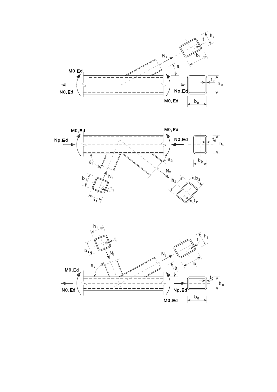
a) Joint with single brace member
b) Gap joint with two brace members
c) Overlap joint with two brace members
)LJXUH'LPHQVLRQVDQGRWKHUSDUDPHWHUVDWDKROORZVHFWLRQODWWLFHJLUGHU
MRLQW
SU(1(
%DVLVRIGHVLJQ
$VVXPSWLRQV
(1)
The design methods given in this part of EN 1993 assume that the standard of construction is as
specified in the execution standards given in 2.8 and that the construction materials and products used
are those specified in EN 1993 or in the relevant material and product specifications.
*HQHUDOUHTXLUHPHQWV
(1)
All joints shall have a design resistance such that the structure is capable of satisfying all the basic
design requirements given in this Standard and in EN 1993-1-1.
(2)
The partial safety factors
M
for joints are given in Table 2.1.
7DEOH3DUWLDOVDIHW\IDFWRUVIRUMRLQWV
Resistance of members and cross-sections
M0
,
M1
and
M2
see EN 1993-1-1
Resistance of bolts
Resistance of rivets
Resistance of pins
M2
Resistance of welds
Resistance of plates in bearing
Slip resistance
- for hybrid connections or connections under fatigue loading
- for other design situations
M3
M3
Bearing resistance of an injection bolt
M4
Resistance of joints in hollow section lattice girder
M5
Resistance of pins at serviceability limit state
M6,ser
Preload of high strength bolts
M7
Resistance of concrete
c
see EN 1992
127(Numerical values for
M
may be defined in the National Annex. Recommended values are as
follows:
M2
= 1,25 ;
M3
= 1,25 for hybrid connections or connections under fatigue loading and
M3
= 1,1 for other design situations;
M4
= 1,0 ;
M5
= 1,0 ;
M6,ser
= 1,0 ;
M7
= 1,1 .
(3)
Joints subject to fatigue should also satisfy the principles given in EN 1993-1-9.
$SSOLHGIRUFHVDQGPRPHQWV
(1)
The forces and moments applied to joints at the ultimate limit state shall be determined according to
the principles in EN 1993-1-1.
5HVLVWDQFHRIMRLQWV
(1)
The resistance of a joint shall be determined on the basis of the resistances of its basic components.
(2)
Linear-elastic or elastic-plastic analysis may be used in the design of joints.

SU(1(
(3)
Where fasteners with different stiffenesses are used to carry a shear load the fasteners with the highest
stiffness should be designed to carry the design load. An exception to this design method is given in
3.9.3.
'HVLJQDVVXPSWLRQV
(1)
Joints shall be designed on the basis of a realistic assumption of the distribution of internal forces and
moments. The following assumptions should be used to determine the distribution of forces:
(a)
the internal forces and moments assumed in the analysis are in equilibrium with the forces and
moments applied to the joints,
(b)
each element in the joint is capable of resisting the internal forces and moments,
(c)
the deformations implied by this distribution do not exceed the deformation capacity of the
fasteners or welds and the connected parts,
(d)
the assumed distribution of internal forces shall be realistic with regard to relative stiffnesses
within the joint,
(e)
the deformations assumed in any design model based on elastic-plastic analysis are based on
rigid body rotations and/or in-plane deformations which are physically possible, and
(f)
any model used is in compliance with the evaluation of test results (see EN 1990).
(2)
The application rules given in this part satisfy 2.5(1).
-RLQWVORDGHGLQVKHDUVXEMHFWWRLPSDFWYLEUDWLRQDQGRUORDGUHYHUVDO
(1)
Where a joint loaded in shear is subject to impact or significant vibration one of the following jointing
methods should be used:
–
welding
–
bolts with locking devices
–
preloaded bolts
–
injection bolts
–
other types of bolt which effectively prevent movement of the connected parts
–
rivets.
(2)
Where slip is not acceptable in a joint (because it is subject to reversal of shear load or for any other
reason), preloaded bolts in a Category B or C connection (see 3.4), fit bolts (see 3.6.1), rivets or
welding should be used.
(3)
For wind and/or stability bracings, bolts in Category A connections (see 3.4) may be used.
(FFHQWULFLW\DWLQWHUVHFWLRQV
(1) Where there is eccentricity at intersections, the joints and members should be designed for the
resulting moments and forces, except in the case of particular types of structures where it has been
demonstrated that it is not necessary, see 5.1.5.
(2)
In the case of joints of angles or tees attached by either a single line of bolts or two lines of bolts any
possible eccentricity should be taken into account in accordance with 2.7(1). In-plane and out-of-plane
eccentricities should be determined by considering the relative positions of the centroidal axis of the
member and of the setting out line in the plane of the connection (see Figure 2.1). For a single angle in
tension connected by bolts on one leg the simplified design method given in 3.10.3 may be used.
127(The effect of eccentricity on angles used as web members in compression is given in
EN 1993-1-1, Annex BB 1.2.
SU(1(
&HQWURLGDOD[HV
)DVWHQHUV
1
2
2
3
3
6HWWLQJRXWOLQHV
)LJXUH6HWWLQJRXWOLQHV
5HIHUHQFHV
This European Standard incorporates by dated or undated reference, provisions from other publications.
These normative references are cited at the appropriate places in the text and the publications are listed
hereafter. For dated references, subsequent amendments to or revisions of any of these publications apply to
this European Standard, only when incorporated in it by amendment or revision. For undated references the
latest edition of the publication referred to applies (including amendments).
5HIHUHQFH6WDQGDUGV*URXS:HOGDEOHVWUXFWXUDOVWHHOV
prEN 10025:2001
Hot rolled products of non-alloy structural steels - Technical delivery conditions
5HIHUHQFH 6WDQGDUGV *URXS 7ROHUDQFHV GLPHQVLRQV DQG WHFKQLFDO
GHOLYHU\FRQGLWLRQV
EN 10029:1991
Hot rolled steel plates 3 mm thick or above - Tolerances on dimensions, shape and
mass
EN 10034:1993
Structural steel I- and H-sections - Tolerances on shape and dimensions
EN 10051:1991
Continuously hot-rolled uncoated plate, sheet and strip of non-alloy and alloy steels -
Tolerances on dimensions and shape
EN 10055:1995
Hot rolled steel equal flange tees with radiused root and toes - Dimensions and
tolerances on shape and dimensions
EN 10056-1:1995
Structural steel equal and unequal leg angles - Part 1: Dimensions
EN 10056-2:1993
Structural steel equal and unequal leg angles - Part 2: Tolerances on shape and
dimensions
EN 10164:1993
Steel products with improved deformation properties perpendicular to the surface of
the product - Technical delivery conditions
5HIHUHQFH6WDQGDUGV*URXS6WUXFWXUDOKROORZVHFWLRQV
EN 10219-1:1997
Cold formed welded structural hollow sections of non-alloy and fine grain steels - Part
1: Technical delivery requirements
EN 10219-2:1997
Cold formed welded structural hollow sections of non-alloy and fine grain steels - Part
2: Tolerances, dimensions and sectional properties
EN 10210-1:1994
Hot finished structural hollow sections of non-alloy and fine grain structural steels -
Part 1: Technical delivery requirements
EN 10210-2:1997
Hot finished structural hollow sections of non-alloy and fine grain structural steels -
Part 2: Tolerances, dimensions and sectional properties

SU(1(
5HIHUHQFH6WDQGDUGV*URXS%ROWVQXWVDQGZDVKHUV
EN 14399-1:2002
High strength structural bolting for preloading - Part 1 : General Requirements
EN 14399-2:2002
High strength structural bolting for preloading - Part 2 : Suitability Test for preloading
EN 14399-3:2002
High strength structural bolting for preloading - Part 3 : System HR -Hexagon bolt and
nut assemblies
EN 14399-4:2002
High strength structural bolting for preloading - Part 4 : System HV -Hexagon bolt
and nut assemblies
EN 14399-5:2002
High strength structural bolting for preloading - Part 5 : Plain washers for system HR
EN 14399-6:2002
High strength structural bolting for preloading - Part 6 : Plain chamfered washers for
systems HR and HV
EN ISO 898-1:1999 Mechanical properties of fasteners made of carbon steel and alloy steel - Part 1: Bolts,
screws and studs (ISO 898-1:1999)
EN 20898-2:1993
Mechanical properties of fasteners - Part 2: Nuts with special proof load values -
Coarse thread (ISO 898-2:1992)
EN ISO 2320:1997
Prevailing torque type steel hexagon nuts - Mechanical and performance requirements
(ISO 2320:1997)
EN ISO 4014:2001
Hexagon head bolts - Product grades A and B (ISO 4014:1999)
EN ISO 4016:2001
Hexagon head bolts - Product grade C (ISO 4016:1999)
EN ISO 4017:2001
Hexagon head screws - Product grades A and B (ISO 4017:1999)
EN ISO 4018:2001
Hexagon head screws - Product grade C (ISO 4018:1999)
EN ISO 4032:2001
Hexagon nuts, style 1 - Product grades A and B (ISO 4032:1999)
EN ISO 4033:2001
Hexagon nuts, style 2 - Product grades A and B (ISO 4033:1999)
EN ISO 4034:2001
Hexagon nuts - Product grade C (ISO 4034:1999)
EN ISO 7040:1997
Prevailing torque hexagon nuts (with non-metallic insert), style 1 - Property classes 5,
8 and 10
EN ISO 7042:1997
Prevailing torque all-metal hexagon nuts, style 2 - Property classes 5, 8, 10 and 12
EN ISO 7719:1997
Prevailing torque type all-metal hexagon nuts, style 1 - Property classes 5, 8 and 10
ISO 286- 2:1988
ISO system of limits and fits - Part 2: Tables of standard tolerance grades and limit
deviations for hole and shafts
ISO 1891:1979
Bolts, screws, nuts and accessories - Terminology and nomenclature - Trilingual
edition
EN ISO 7089:2000
Plain washers- Nominal series- Product grade A
EN ISO 7090:2000
Plain washers, chamfered - Normal series - Product grade A
EN ISO 7091:2000
Plain washers - Normal series - Product grade C
EN ISO 10511:1997 Prevailing torque type hexagon thin nuts (with non-metallic insert)
EN ISO 10512:1997 Prevailing torque type hexagon nuts thin nuts, style 1, with metric fine pitch thread -
Property classes 6, 8 and 10
EN ISO 10513:1997 Prevailing torque type all-metal hexagon nuts, style 2, with metric fine pitch thread -
Property classes 8, 10 and 12
5HIHUHQFH6WDQGDUGV*URXS:HOGLQJFRQVXPDEOHDQGZHOGLQJ
EN 12345:1998
Welding-Multilingual terms for welded joints with illustrations. September 1998.
EN ISO 14555:1995 Welding-Arc stud welding of metallic materials. May 1995
Pr EN ISO 13918:1997 Welding-Studs for arc stud welding-January 1997

SU(1(
EN 288-3:1992
Specification and approval of welding procedures for metallic materials. Part 3:
Welding procedure tests for arc welding of steels. 1992
Pr EN ISO 5817:2000 Arc-welded joints in steel - Guidance for quality levels for imperfections
5HIHUHQFH6WDQGDUGV*URXS5LYHWV
127(Reference should be given in the National Annex.
5HIHUHQFH6WDQGDUG*URXS([HFXWLRQRIVWHHOVWUXFWXUHV
EN 1090
Requirements for the execution of steel structures

SU(1(
&RQQHFWLRQVPDGHZLWKEROWVULYHWVRUSLQV
%ROWVQXWVDQGZDVKHUV
*HQHUDO
(1)
All bolts, nuts and washers should comply with 2.8 Reference Standards: Group 4.
(2)
The rules in this Standard are valid for the bolt classes given in Table 3.1.
(3)
The yield strength
I
yb
and the ultimate tensile strength
I
ub
for bolt classes 4.6, 5.6, 6.8, 8.8 and 10.9 are
given in Table 3.1. These values should be adopted as characteristic values in design calculations.
7DEOH1RPLQDOYDOXHVRIWKH\LHOGVWUHQJWKI
\E
DQGWKHXOWLPDWHWHQVLOH
VWUHQJWKI
XE
IRUEROWV
Bolt class
4.6
5.6
6.8
8.8
10.9
I
yb
(N/mm
2
)
240
300
480
640
900
I
ub
(N/mm
2
)
400
500
600
800
1000
3UHORDGHGEROWV
(1)
Only bolt assemblies of classes 8.8 and 10.9 conforming to the requirements given in 2.8 Reference
Standards: Group 4 for High Strength Structural Bolting with controlled tightening in accordance with
the requirements in 2.8 Reference Standards: Group 7 may be used as preloaded bolts.
5LYHWV
(1)
The material properties, dimensions and tolerances of steel rivets should comply with the requirements
given in 2.8 Reference Standards: Group 6.
$QFKRUEROWV
(1)
The following materials may be used for anchor bolts:
–
Steel grades conforming to 2.8 Reference Standards: Group 1;
–
Steel grades conforming to 2.8 Reference Standards: Group 4;
–
Steel grades used for reinforcing bars conforming to EN 10080,
provided that the nominal yield strength does not exceed 640 N/mm
2
when the anchor bolts are
required to act in shear and not more than 900 N/mm
2
otherwise.
&DWHJRULHVRIEROWHGFRQQHFWLRQV
6KHDUFRQQHFWLRQV
(1)
Bolted connections loaded in shear should be designed as one of the following:
a)
&DWHJRU\$%HDULQJW\SH
In this category bolts from class 4.6 up to and including class 10.9 should be used. No preloading and
special provisions for contact surfaces are required. The design ultimate shear load should not exceed
the design shear resistance, obtained from 3.6, nor the design bearing resistance, obtained from 3.6 and
3.7.

SU(1(
b)
&DWHJRU\%6OLSUHVLVWDQWDWVHUYLFHDELOLW\OLPLWVWDWH
In this category preloaded bolts in accordance with 3.1.2(1) should be used. Slip should not occur at
the serviceability limit state. The design serviceability shear load should not exceed the design slip
resistance, obtained from 3.9. The design ultimate shear load should not exceed the design shear
resistance, obtained from 3.6, nor the design bearing resistance, obtained from 3.6 and 3.7.
c)
&DWHJRU\&6OLSUHVLVWDQWDWXOWLPDWHOLPLWVWDWH
In this category preloaded bolts in accordance with 3.1.2(1) should be used. Slip should not occur at
the ultimate limit state. The design ultimate shear load should not exceed the design slip resistance,
obtained from 3.9, nor the design bearing resistance, obtained from 3.6 and 3.7. In addition for a
connection in tension, the design plastic resistance of the net cross-section at bolt holes
1
net,Rd
, (see 6.2
of EN 1993-1-1), should be checked, at the ultimate limit state.
The design checks for these connections are summarised in Table 3.2.
7HQVLRQFRQQHFWLRQV
(1)
Bolted connection loaded in tension should be designed as one of the following:
a)
&DWHJRU\'QRQSUHORDGHG
In this category bolts from class 4.6 up to and including class 10.9 should be used. No preloading is
required. This category should not be used where the connections are frequently subjected to
variations of tensile loading. However, they may be used in connections designed to resist normal
wind loads.
b)
&DWHJRU\(SUHORDGHG
In this category preloaded 8.8 and 10.9 bolts with controlled tightening in conformity with 2.8
Reference Standards: Group 7 should be used.
The design checks for these connections are summarised in Table 3.2.
7DEOH&DWHJRULHVRIEROWHGFRQQHFWLRQV
Category
Criteria
Remarks
6KHDUFRQQHFWLRQV
A
bearing type
)
v,Ed
)
v,Rd
)
v,Ed
)
b,Rd
No preloading required.
Bolt classes from 4.6 to 10.9 may be used.
B
slip-resistant at serviceability
)
v,Ed.ser
)
s,Rd,ser
)
v,Ed
)
v,Rd
)
v,Ed
)
b,Rd
Preloaded 8.8 or 10.9 bolts should be used.
For slip resistance at serviceability see 3.9.
C
slip-resistant at ultimate
)
v,Ed
)
s,Rd
)
v,Ed
)
b,Rd
)
v,Ed
1
net,Rd
Preloaded 8.8 or 10.9 bolts should be used.
For slip resistance at ultimate see 3.9.
1
net,Rd
see EN 1993-1-1
7HQVLRQFRQQHFWLRQV
D
non-preloaded
)
t,Ed
)
t,Rd
)
t,Ed
%
p,Rd
No preloading required.
Bolt classes from 4.6 to 10.9 may be used.
%
p,Rd
see Table 3.4.
E
preloaded
)
t,Ed
)
t,Rd
)
t,Ed
%
p,Rd
Preloaded 8.8 or 10.9 bolts should be used.
%
p,Rd
see Table 3.4.
The design tensile force
)
t,Ed
should include any force due to prying action, see 3.11. Bolts subjected to
both shear force and tensile force should also satisfy the criteria given in Table 3.4.

SU(1(
127( When the preload is not explicitly used in the design calculations for shear resistances but is
required for execution purposes or as a quality measure (e.g. fordurability) then the level of preload
can be specified in the National Annex.
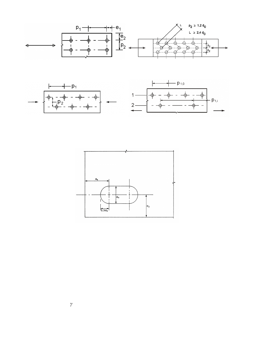
3RVLWLRQLQJRIKROHVIRUEROWVDQGULYHWV
(1)
Minimum and maximum spacing and end and edge distances for bolts and rivets are given in Table
3.3.
(2)
Minimum and maximum spacing, end and edge distances for structures subjected to fatigue, see EN
1993-1-9.
7DEOH0LQLPXPDQGPD[LPXPVSDFLQJHQGDQGHGJHGLVWDQFHV
Minimum
Maximum
1) 2) 3)
Structures made from steels conforming to
EN 10025 except steels conforming to
EN 10025-5
Structures made from
steels conforming to
EN 10025-5
Distances and
spacings,
see Figure 3.1
Steel exposed to the
weather or other
corrosive influences
Steel not exposed to
the weather or other
corrosive influences
Steel used
unprotected
End distance
H
1
1,2
G
0
4
W + 40 mm
The larger of
8
W or 125 mm
Edge distance
H
2
1,2
G
0
4
W + 40 mm
The larger of
8
W or 125 mm
Distance
H
3
in slotted holes
1,5
G
0
4)
Distance
H
4
in slotted holes
1,5
G
0
4)
Spacing
S
1
2,2
G
0
The smaller of
14
W or 200 mm
The smaller of
14
W or 200 mm
The smaller of
14
W
min
or 175 mm
Spacing
S
1,0
The smaller of
14
W or 200 mm
Spacing
S
1,i
The smaller of
28
W or 400 mm
Spacing
S
2
5)
2,4
G
0
The smaller of
14
W or 200 mm
The smaller of
14
W or 200 mm
The smaller of
14
W
min
or 175 mm
1)
Maximum values for spacings, edge and end distances are unlimited, except in the following cases:
–
for compression members in order to avoid local buckling and to prevent corrosion in exposed
members and;
–
for exposed tension members to prevent corrosion.
2)
The local buckling resistance of the plate in compression between the fasteners should be calculated
according to EN 1993-1-1 using 0,6
S
i
as buckling length. Local buckling between the fasteners
need not to be checked if
S
1
/
W is smaller than 9 . The edge distance should not exceed the local
buckling requirements for an outstand element in the compression members, see EN 1993-1-1. The
end distance is not affected by this requirement.
3)
W is the thickness of the thinner outer connected part.
4)
The dimensional limits for slotted holes are given in 2.8 Reference Standards: Group 7.
5)
For staggered rows of fasteners a minimum line spacing of
S
2
= 1,2
G
0
may be used, provided that the
minimum distance, L, between any two fasteners is greater than 2,4
G
0
, see Figure 3.1b).
SU(1(
6WDJJHUHG5RZVRIIDVWHQHUV
a) Symbols for spacing of fasteners
b) Symbols for staggered spacing
p
1
≤ 14 t and ≤ 200 mm
p
2
≤ 14 t and ≤ 200 mm
p
1,0
≤ 14 t and ≤ 200 mm p
1,i
≤ 28 t and ≤ 400 mm
RXWHUURZ
LQQHUURZ
c) Staggered spacing – compression
d) Spacing in tension members
e) End and edge distances for slotted holes
)LJXUH6\PEROVIRUHQGDQGHGJHGLVWDQFHVDQGVSDFLQJRIIDVWHQHUV
'HVLJQUHVLVWDQFHRILQGLYLGXDOIDVWHQHUV
%ROWVDQGULYHWV
(1)
The design resistance for an individual fastener subjected to shear and/or tension is given in Table 3.4.
(2) For preloaded bolts in accordance with 3.1.2(1) the design preload,
)
p,Cd
,to be used in design
calculations should be taken as:
)
p,Cd
= 0,7
I
ub
$
s
/
M7
...
(3.1)
127(Where the preload is not used in design calculations the guidance given in the note to Table
3.2 should be followed.
SU(1(
(3)
The design resistances for tension and for shear through the threaded portion of a bolt given in Table
3.4 should only be used for bolts manufactured in conformity with 2.8 Reference Standard: Group 4.
For bolts with cut threads, such as anchor bolts or tie rods fabricated from round steel bars where the
threads comply with EN1090, the relevant values from Table 3.4 should be used. For bolts with cut
threads where the threads do not comply with EN1090 the relevant values from Table 3.4 should be
multiplied by a factor of 0,85.
(4)
The design shear resistance
)
v,Rd
given in Table 3.4 should only be used where the bolts are used in
holes with nominal clearances not exceeding those for normal holes as specified in 2.8 Reference
Standards: Group 7.
(5)
M12 and M14 bolts may also be used in 2 mm clearance holes provided that the design resistance of
the bolt group based on bearing is greater or equal to the design resistance of the bolt group based on
bolt shear. In addition for class 4.8, 5.8, 6.8, 8.8 and 10.9 bolts the design shear resistance
)
v,Rd
should
be taken as 0,85 times the value given in Table 3.4.
(6)
Fit bolts should be designed using the method for bolts in normal holes.
(7)
The thread of a fit bolt should not be included in the shear plane.
(8)
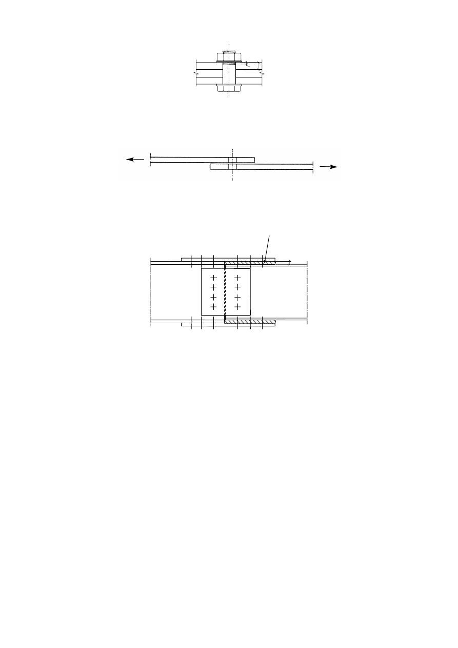
The length of the threaded portion of a fit bolt included in the bearing length should not exceed 1/3 of
the thickness of the plate, see Figure 3.2.
(9)
The hole tolerance used for fit bolts should be in accordance with 2.8 Reference Standards: Group 7.
(10) In single lap joints with only one bolt row, see Figure 3.3, the bolts should be provided with washers
under both the head and the nut. The design bearing resistance
)
b,Rd
for each bolt should be limited to:
)
b,Rd
I
u
GW /
M2
...
(3.2)
127(Single rivets should not be used in single lap joints.
(11) In the case of class 8.8 or 10.9 bolts, hardened washers should be used for single lap joints with only
one bolt or one row of bolts.
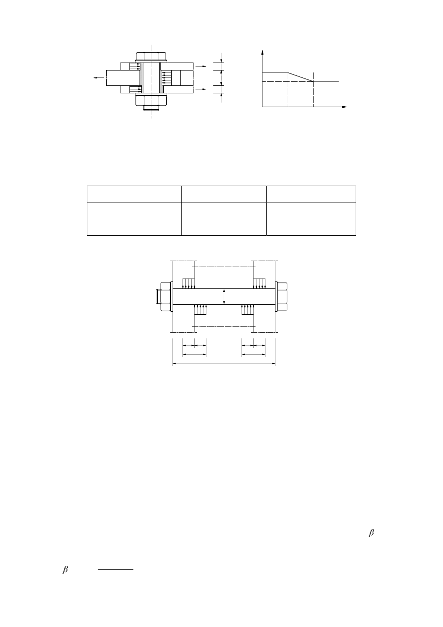
(12) Where bolts or rivets transmitting load in shear and bearing pass through packing of total thickness
W
p
greater than one-third of the nominal diameter
G, see Figure 3.4, the design shear resistance )
v,Rd
calculated as specified in Table 3.4, should be multiplying by a reduction factor
p
given by:
p
=
S
W
G
G
3
8
9
+
but
p
...
(3.3)
(13) For double shear connections with packing on both sides of the splice,
W
p
should be taken as the
thickness of the thicker packing.
(14) Riveted connections should be designed to transfer shear forces. If tension is present the design tensile
force
)
t.Ed
should not exceed the design tension resistance
)
t,Rd
given in Table 3.4.
(15) For grade S 235 steel the "as driven" value of
I
ur
may be taken as 400 N/mm
2
.
(16) As a general rule, the grip length of a rivet should not exceed 4,5
G for hammer riveting and 6,5G for
press riveting.
SU(1(
t
<t/3
)LJXUH7KUHDGHGSRUWLRQRIWKHVKDQNLQWKHEHDULQJOHQJWKIRUILWEROWV
)LJXUH6LQJOHODSMRLQWZLWKRQHURZRIEROWV
3DFNLQJSODWHV
t
p
)LJXUH)DVWHQHUVWKURXJKSDFNLQJV
SU(1(
7DEOH'HVLJQUHVLVWDQFHIRULQGLYLGXDOIDVWHQHUVVXEMHFWHGWRVKHDUDQGRU
WHQVLRQ
Failure mode
Bolts
Rivets
Shear resistance per shear
plane
)
v,Rd
=
2
0
XE
Y
$
I
γ
α
- where the shear plane passes through the
threaded portion of the bolt (
$ is the tensile stress
area of the bolt
$
s
):
- for classes 4.6, 5.6 and 8.8:
v
= 0,6
- for classes 4.8, 5.8, 6.8 and 10.9:
v
= 0,5
- where the shear plane passes through the
unthreaded portion of the bolt (
$ is the gross cross
VHFWLRQRIWKHEROW
v
= 0,6
)
v,Rd
=
2
0
6
,
0
0
XU
$
I
γ
Bearing resistance
1), 2), 3)
)
b,Rd
=
2
1
0
X
E
W
G
I
D
N
γ
ZKHUH
b
LVWKHVPDOOHVWRI
d
;
X
XE
I
I
or 1,0;
in the direction of load transfer:
- for end bolts:
d
=
0
1
3
G
H
; for inner bolts:
d
=
4
1
3
0
1
−
G
S
perpendicular to the direction of load transfer:
- for edge bolts:
N
1
is the smallest of
7
,
1
8
,
2
0
2
−
G
H
or 2,5
- for inner bolts:
N
1
is the smallest of
7
,
1
4
,
1
0
2
−
G
S
or 2,5
Tension resistance
2)
)
t,Rd
=
2
2
0
V
XE
$
I
N
γ
where
N
2
= 0,63 for countersunk bolt,
otherwise
N
2
= 0,9.
)
t,Rd
=
2
0
6
,
0
0
XU
$
I
γ
Punching shear resistance
%
p,Rd
=
0,6
G
m
W
p
I
u
/
M2
No check needed
Combined shear and
tension
0
,
1
4
,
1
,
,
,
,
≤
+
5G
W
(G
W
5G
Y
(G
Y
)
)
)
)
1)
The bearing resistance
)
b,Rd
for bolts
–
in oversized holes is 0,8 times the bearing resistance for bolts in normal holes.
–
in slotted holes, where the longitudinal axis of the slotted hole is perpendicular to the direction of
the force transfer, is 0,6 times the bearing resistance for bolts in round, normal holes.
2)
For countersunk bolt:
–
the bearing resistance
)
b,Rd
should be based on a plate thickness
W equal to the thickness of the
connected plate minus half the depth of the countersinking.
–
for the determination of the tension resistance
)
t,Rd
the angle and depth of countersinking should
conform with 2.8 Reference Standards: Group 4, otherwise the tension resistance
)
t,Rd
should be
adjusted accordingly.
3)
When the load on a bolt is not parallel to the edge, the bearing resistance may be verified separately
for the bolt load components parallel and normal to the end.

SU(1(
,QMHFWLRQEROWV
*HQHUDO
(1)
Injection bolts may be used as an alternative to ordinary bolts and rivets for category A, B and C
connections specified in 3.4.
(2)
Fabrication and erection details for injection bolts are given in 2.8 Reference Standards: Group 7.
'HVLJQUHVLVWDQFH
(1)
The design method given in 3.6.2.2(2) to 3.6.2.2(6) should be used for connections with injection bolts
of class 8.8 or 10.9. Bolt assemblies should conform with the requirements given in 2.8 Reference
Standards: Group 4, but see 3.6.2.2(3) for when preloaded bolts are used.
(2)
The design ultimate shear load of any bolt in a Category A connection shall not exceed the smaller of
the following: the design shear resistance of the bolt as obtained from 3.6 and 3.7; the design bearing
resistance of the resin as obtained from 3.6.2.2(5).
(3)
Preloaded injection bolts should be used for category B and C connections, for which preloaded bolt
assemblies in accordance with 3.1.2(1) should be used.
(4)
The design serviceability shear load of any bolt in a category B connection and the design ultimate
shear load of any bolt in a category C connection shall not exceed the design slip resistance of the bolt
as obtained from 3.9 at the relevant limit state plus the design bearing resistance of the resin as
obtained from 3.6.2.2(5) at the relevant limit state. In addition the design ultimate shear load of a bolt
in a category B or C connection shall not exceed either the design shear resistance of the bolt as
obtained from 3.6, nor the design bearing resistance of the bolt as obtained from 3.6 and 3.7.
(5)
The design bearing resistance of the resin, F
b,Rd.resin
, may be determined according to the following
equation:
)
b,Rd,resin
=
4
sin
,
sin
,
0
UH
E
UH
E
V
W
I
W
G
N
N
γ
β
...
(3.4)
where:
)
b,Rd,resin
is the bearing strength of an injection bolt
is a coefficient depending of the thickness ratio of the connected plates as given in Table 3.5
and Figure 3.5
I
b,resin
is the bearing strength of the resin to be determined according to the 2.8 Reference Standards:
Group 7.
W
b, resin
is the effective bearing thickness of the resin, given in Table 3.5
N
t
is 1,0 for serviceability limit state (long duration)
is
1,2
for
ultimate
limit
state
N
s
is taken as 1,0 for holes with normal clearances or (1,0 - 0,1 m), for oversized holes
P
is the difference (in mm) between the normal and oversized hole dimensions. In the case of
short slotted holes as specified in 2.8 Reference Standards: Group 7,
P = 0.5 x (the difference
(in mm) between the hole length and width).
(6)
When calculating the bearing resistance of a bolt with a clamping length exceeding 3
G, a value of not
more than 3
G should be taken to determine the effective bearing thickness W
b,resin
(see Figure 3.6).
SU(1(
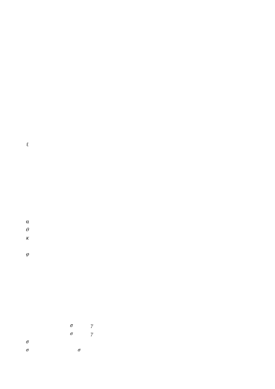
σ
σ
σ
σ
σ
σ
1
1
1
2
2
2
1
2
2
1
2
t
t
t
t
1.0
1,0
1,33
2.0
/
β
t
)LJXUH)DFWRUDVDIXQFWLRQRIWKHWKLFNQHVVUDWLRRIWKHFRQQHFWHGSODWHV
7DEOH9DOXHVRI
DQG
W
EUHVLQ
W
l
/
W
2
W
b,resin
1,0 <
W
l
/
W
2
< 2,0
1,0
1,66 - 0,33 (
W
1
/
W
2
)
1,33
2
W
2
G
W
1
G
W
1
G
d
1 . 5 d
1 . 5 d
5
)LJXUH/LPLWLQJHIIHFWLYHOHQJWKIRUORQJLQMHFWLRQEROWV
*URXSRIIDVWHQHUV
(1)
The design resistance of a group of fasteners may be taken as the sum of the design bearing resistances
)
b,Rd
of the individual fasteners provided that the design shear resistance
)
v,Rd
of each individual
fastener is greater than or equal to the design bearing resistance
)
b,Rd
. Otherwise the design resistance
of a group of fasteners should be taken as the number of fasteners multiplied by the smallest design
resistance of any of the individual fasteners.
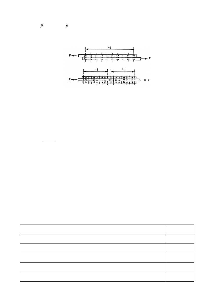
/RQJMRLQWV
(1)
Where the distance
/
j
between the centres of the end fasteners in a joint, measured in the direction of
force transfer (see Figure 3.7), is more than 15 d, the design shear resistance
)
v,Rd
of all the fasteners
calculated according to Table 3.4 should be reduced by multiplying it by a reduction factor
Lf
, given
by:
Lf
=
G
G
/
M
200
15
1
−
−
... (3.5)
SU(1(
but
Lf
DQG
Lf
(2)
The provision in 3.8(1) does not apply where there is a uniform distribution of force transfer over the
length of the joint, e.g. the transfer of shear force between the web and the flange of a section.
)LJXUH/RQJMRLQWV
6OLSUHVLVWDQWFRQQHFWLRQVXVLQJRUEROWV
'HVLJQ6OLSUHVLVWDQFH
(1)
The design slip resistance of a preloaded class 8.8 or 10.9 bolt should be taken as:
)
s,Rd
=
3
0
V
Q
N
γ
µ
)
p,C
...
(3.6)
where:
N
s
is
given in Table 3.6
Q is the number of the friction surfaces
is the slip factor obtained either by specific tests for the friction surface in accordance with 2.8
Reference Standards: Group 7 or when relevant as given in Table 3.7.
(2)
For class 8.8 and 10.9 bolts conforming with 2.8 Reference Standards: Group 4, with controlled
tightening in conformity with 2.8 Reference Standards: Group 7, the preloading force
)
p,C
to be used
in equation (3.6) should be taken as:
)
p,C
= 0,7
I
ub
$
s
... (3.7)
7DEOH9DOXHVRIN
V
Description
N
s
Bolts in normal holes.
1,0
Bolts in either oversized holes or short slotted holes with the axis of the slot
perpendicular to the direction of load transfer.
0,85
Bolts in long slotted holes with the axis of the slot perpendicular to the direction of load
transfer.
0,7
Bolts in short slotted holes with the axis of the slot parallel to the direction of load
transfer.
0,76
Bolts in long slotted holes with the axis of the slot parallel to the direction of load
transfer.
0,63

SU(1(
7DEOH6OLSIDFWRUIRUSUHORDGHGEROWV
Class of friction surfaces (see 2.8 Reference
Standard: Group 7)
Slip factor
A
0,5
B
0,4
C
0,3
D
0,2
127( The requirements for testing and inspection are given in 2.8 Reference Standards:
Group 7.
127( The classification of any other surface treatment should be based on test specimens
representative of the surfaces used in the structure using the procedure set out in 2.8 Reference
Standards: Group 7.
127( The definitions of the class of friction surface are given in 2.8 Reference Standards:
Group 7.
127( With painted surface treatments account should made for any loss of pre-load which
occur over time.
&RPELQHGWHQVLRQDQGVKHDU
(1)
If a slip-resistant connection is subjected to an applied tensile force,
)
t,Ed
or
)
t,Ed,serv
, in addition to the
shear force,
)
v,Ed
or
)
v,Ed,serv
, tending to produce slip, the design slip resistance per bolt should be taken
as follows:
for a category B connection:
)
s,Rd,serv
=
3
,
,
,
)
8
,
0
(
0
VHUY
(G
W
&
S
V
)
)
Q
N
γ
µ
−
... (3.8a)
for a category C connection:
)
s,Rd
=
3
,
,
)
8
,
0
(
0
(G
W
&
S
V
)
)
Q
N
γ
µ
−
... (3.8b)
(2)
If, in a moment connection, a contact force on the compression side counterbalances the applied
tensile force no reduction in slip resistance is required.
+\EULGFRQQHFWLRQV
(1)
As an exception to 2.4(3) , preloaded class 8.8 and 10.9 bolts in connections designed as slip-resistant
at the ultimate limit state (Category C in 3.4) may be assumed to share load with welds, provided that
the final tightening of the bolts is carried out after the welding is complete.
'HGXFWLRQVIRUIDVWHQHUKROHV
*HQHUDO
(1)
Deduction for holes in the member design should be made according to EN 1993-1-1.
SU(1(
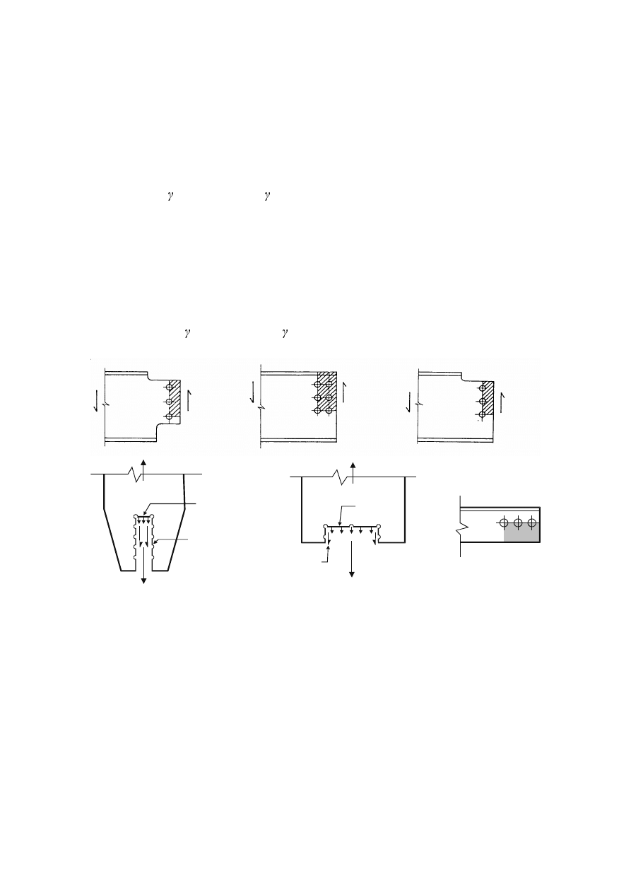
'HVLJQIRUEORFNWHDULQJ
(1)
Block tearing consists of failure in shear at the row of bolts along the shear face of the hole group
accompanied by tensile rupture along the line of bolt holes on the tension face of the bolt group.
Figure 3.8 shows block tearing.
(2)
For a symmetric bolt group subject to concentric loading the design block tearing resistance,
9
eff,1,Rd
is
given by:
9
eff,1,Rd
= f
u
A
nt
/
M2
+ (1 /
¥I
y
A
nv
/
M0
...
(3.9)
where:
$
nt
is net area subjected to tension;
$
nv
is net area subjected to shear.
(3)
For a bolt group subject to eccentric loading the design block shear tearing resistance
9
eff,2,Rd
is given
by:
9
eff,2,Rd
= 0,5 f
u
A
nt
/
M2
+ (1 /
¥I
y
A
nv
/
M0
...
(3.10)
1
6G
1
6G
1
6G
1
6G
VPDOOWHQVLRQIRUFH
ODUJHVKHDUIRUFH
VPDOOVKHDUIRUFH
ODUJHWHQVLRQIRUFH
)LJXUH%ORFNWHDULQJ
SU(1(
$QJOHVFRQQHFWHGE\RQHOHJDQGRWKHUXQV\PPHWULFDOO\FRQQHFWHGPHPEHUVLQWHQVLRQ
(1)
The eccentricity in joints, see 2.7(1), and the effects of the spacing and edge distances of the bolts,
shall be taken into account in determining the design resistance of:
–
unsymmetrical members;
–
symmetrical members that are connected unsymmetrically, such as angles connected by one leg.
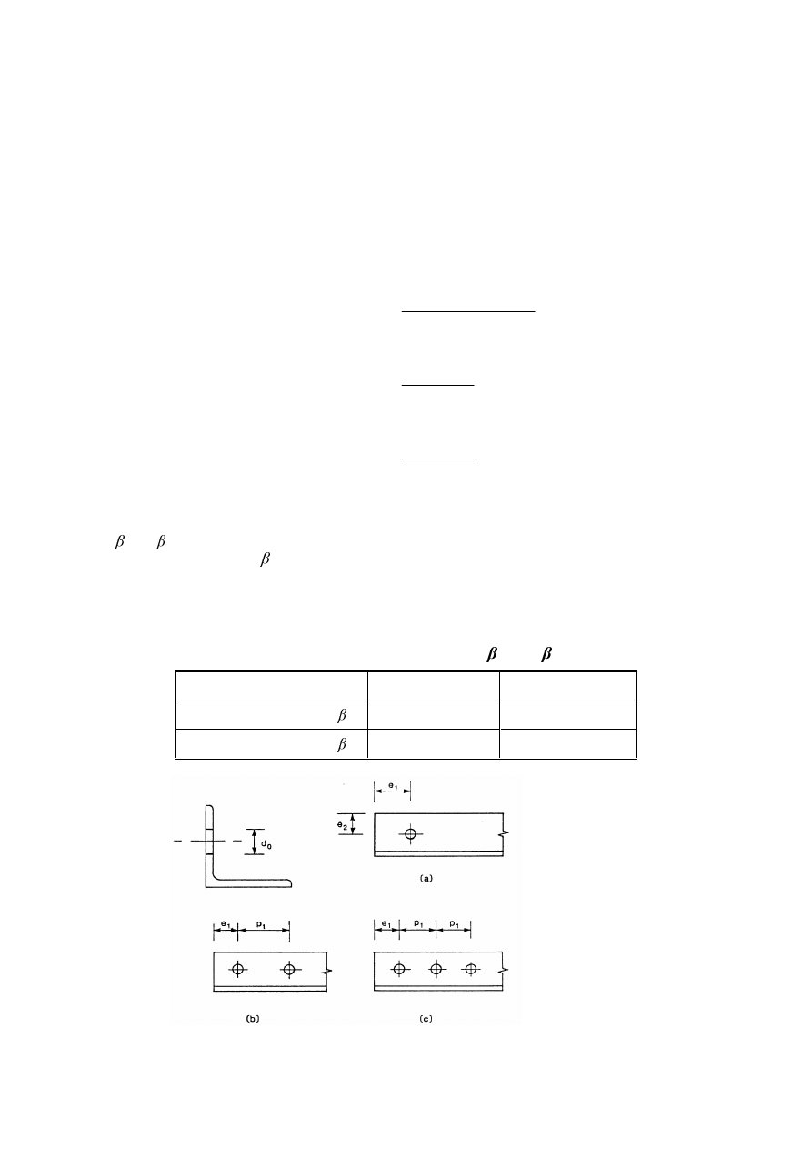
(2)
A single angle in tension connected by a single row of bolts in one leg, see Figure 3.9, may be treated
as concentrically loaded over an effective net section for which the design ultimate resistance should
be determined as follows:
with
1
bolt:
1
u,Rd
=
2
0
2
)
5
,
0
(
0
,
2
0
X
I
W
G
H
γ
−
...
(3.11)
with
2
bolts:
1
u,Rd
=
2
2
0
X
QHW
I
$
γ
β
...
(3.12)
with 3 or more bolts:
1
u,Rd
=
2
3
0
X
QHW
I
$
γ
β
...
(3.13)
where:
2
and
3
are reduction factors dependent on the pitch p
1
as given in Table 3.8. For intermediate values
of p
1
the value of may be determined by linear interpolation;
A
net
is the net area of the angle. For an unequal-leg angle connected by its smaller leg, A
net
should
be taken as equal to the net section area of an equivalent equal-leg angle of leg size equal to that
of the smaller leg.
7DEOH5HGXFWLRQIDFWRUV
DQG
Pitch p
1
G
o
G
o
2 bolts
2
0,4
0,7
3 bolts or more
3
0,5
0,7
a) 1 bolt
b) 2 bolts
c) 3 bolts
)LJXUH$QJOHVFRQQHFWHGE\RQHOHJ
SU(1(
/XJDQJOHV
(1)
The Lug angle shown in Figure 3.10 connects angle members and their fasteners to a gusset or other
supporting part and should be designed to transmit a force 1,2 times the force in the outstand of the
angle connected.
(2)
The fasteners connecting the lug angle to the outstand of the angle member should be designed to
transmit a force 1,4 times the force in the outstand of the angle member.
(3)
Lug angles connecting a channel or a similar member should be designed to transmit a force 1,1 times
the force in the channel flanges to which they are attached.
(4)
The fasteners connecting the lug angle to the channel or similar member should be designed to
transmit a force 1,2 times the force in the channel flange which they connect.
(5)
In no case should less than two bolts or rivets be used to attach a lug angle to a gusset or other
supporting part.
(6)
The connection of a lug angle to a gusset plate or other supporting part should terminate at the end of
the member connected. The connection of the lug angle to the member should run from the end of the
member to a point beyond the direct connection of the member to the gusset or other supporting part.
)LJXUH/XJDQJOHV
3U\LQJIRUFHV
(1)
Where fasteners are required to carry an applied tensile force, they should be designed to resist the
additional force due to prying action, where this can occur.
127(The rules given in 6.2.4 implicitly account for prying forces.
'LVWULEXWLRQRIIRUFHVEHWZHHQIDVWHQHUVDWWKHXOWLPDWHOLPLWVWDWH
(1)
When a moment is applied to a joint, the distribution of internal forces may be either linear (i.e.
proportional to the distance from the centre of rotation) or plastic, (i.e. any distribution that is in
equilibrium is acceptable provided that the resistances of the components are not exceeded and the
ductility of the components is sufficient).
(2)
The elastic linear distribution of internal forces should be used for the following:
–
when bolts are used creating a category C slip-resistant connection,
–
in shear connections where the design shear resistance
)
v,Rd
of a fastener is less than the design
bearing resistance
)
b,Rd
,
–
where connections are subjected to impact, vibration or load reversal (except wind loads).
(3) When a joint is loaded by a concentric shear only, the load may be assumed to be uniformly
distributed amongst the fasteners, provided that the size and the class of fasteners is the same.
SU(1(
&RQQHFWLRQVPDGHZLWKSLQV
*HQHUDO
(1)
Wherever there is a risk of pins becoming loose, they should be secured.
(2)
Pin connections in which no rotation is required may be designed as single bolted connections,
provided that the length of the pin is less than 3 times the diameter of the pin, see 3.6.1. For all other
cases the method given in 3.13.2 should be followed.
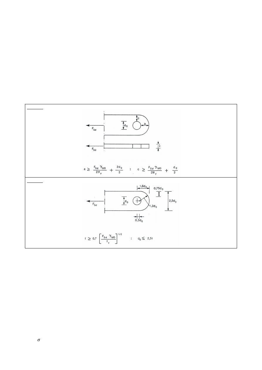
(3)
In pin-connected members the geometry of the unstiffnened element that contains a hole for the pin
should satisfy the dimensional requirements given in Table 3.9.
7DEOH*HRPHWULFDOUHTXLUHPHQWVIRUSLQHQGHGPHPEHUV
Type A:
Given thickness t
Type B:
Given geometry
(4)
Pin connected members should be arranged such to avoid eccentricity and should be of sufficient size
to distribute the load from the area of the member with the pin hole into the member away from the
pin.
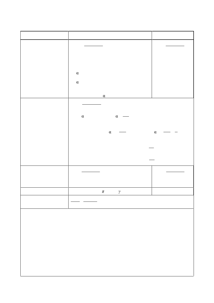
'HVLJQRISLQV
(1)
The design requirements for solid circular pins are given in Table 3.10.
(2)
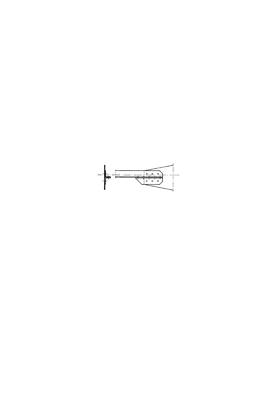
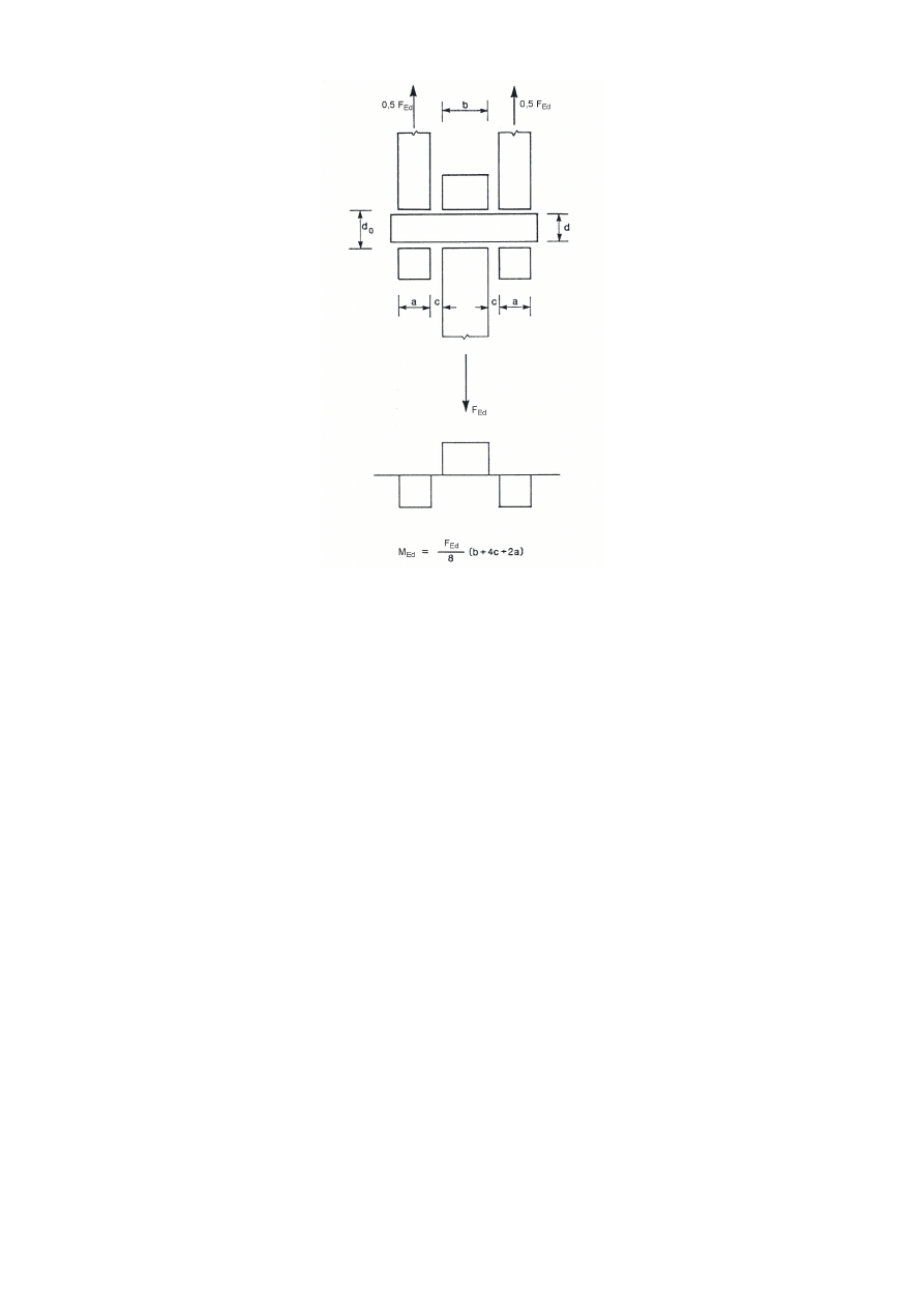
The moments in a pin should be calculated on the basis that the connected parts form simple supports.
It should be generally assumed that the reactions between the pin and the connected parts are
uniformly distributed along the length in contact on each part as indicated in Figure 3.11.
(3)
If the pin is intended to be replaceable, in addition to the provisions given in 3.13.1 to 3.13.2, the
contact bearing stress should satisfy:
h,Ed
I
h,Rd
... (3.14)
SU(1(
where:
h,Ed
=
W
G
G
G
)
(
VHU
(G
2
0
,
)
(
591
,
0
−
...
(3.15)
f
h,Ed
= 2,5
f
y
/
M6,ser
... (3.16)
where:
d
is the diameter of the pin;
d
0
is the diameter of the pin hole;
F
Ed,ser
is the design value of the force to be transferred in bearing, under the characteristic load
combination for serviceability limit states.
7DEOH'HVLJQFULWHULDIRUSLQFRQQHFWLRQV
Failure mode
Design requirements
Shear resistance of the pin
)
v,Rd
= 0,6
$ I
up
/
M2
)
v,Ed
Bearing resistance of the plate and the pin
If the pin is intended to be replaceable this
requirement should also be satisfied.
)
b,Rd
= 1,5
W G I
y
/
M0
)
b,Ed
)
b,Rd,ser
=
0,6
W G I
y
/
M6,ser
)
b,Ed,ser
Bending resistance of the pin
If the pin is intended to be replaceable this
requirement should also be satisfied.
0
Rd
= 1,5 W
e
f
yp
/
M0
0
Ed
0
Rd,ser
= 0,8 W
e
f
yp
/
M6,ser
0
Ed,ser
Combined shear and bending resistance of the pin
2
,
,
2
+
5G
Y
(G
Y
5G
(G
)
)
0
0
G
is
the diameter of the pin;
I
y
is
the lower of the design strengths of the pin and the connected part;
I
up
is
the ultimate tensile strength of the pin;
I
yp
is
the yield strength of the pin;
W
is
the thickness of the connected part;
$
is
the cross-sectional area of a pin.
SU(1(
)LJXUHBending moment in a SLQ

SU(1(
:HOGHGFRQQHFWLRQV
*HQHUDO
(1)
The provisions in this section apply to weldable structural steels conforming to EN 1993-1-1 and to
material thicknesses of 4 mm and over. The provisions also apply to joints in which the mechanical
properties of the weld metal are compatible with those of the parent metal, see 4.2.
For welds in thinner material reference should be made to EN 1993 part 1.3 and for welds in structural
hollow sections in material thicknesses of 2,5 mm and over guidance is given section 7 of this
Standard.
For stud welding reference should be made to EN 1994-1-1.
127(Further guidance on stud welding can be found in EN ISO 14555 and EN ISO 13918.
(2)
Welds subject to fatigue shall also satisfy the principles given in EN 1993-1-9.
(3)
Quality level C according to EN ISO 25817 is usually required, if not otherwise specified. The
frequency of inspection of welds should be specified in accordance with the rules in 2.8 Reference
Standards: Group 7. The quality level of welds should be chosen according to EN ISO 25817. For the
quality level of welds used in fatigue loaded structures, see EN 1993-1-9.
(4)
Lamellar tearing shall be avoided.
(5)
Guidance on lamellar tearing is given in EN 1993-1-10.
:HOGLQJFRQVXPDEOHV
(1) All welding consumables should conform to the relevant standards specified in 2.8 Reference
Standards; Group 5.
(2)
The specified yield strength, ultimate tensile strength, elongation at failure and minimum Charpy
V-notch energy value of the filler metal, should be equivalent to, or better than that specified for the
parent material.
127( Generally it is safe to use electrodes that are overmatched with regard to the steel grades
being used.
*HRPHWU\DQGGLPHQVLRQV
7\SHRIZHOG
(1)
This Standard covers the design of fillet welds, fillet welds all round, butt welds, plug welds and flare
groove welds. Butt welds may be either full penetration butt welds or partial penetration butt welds.
Both fillet welds all round and plug welds may be either in circular holes or in elongated holes.
(2)
The most common types of joints and welds are illustrated in EN 12345.
)LOOHWZHOGV
*HQHUDO
(1)
Fillet welds may be used for connecting parts where the fusion faces form an angle of between 60° and
120°.

SU(1(
(2)
Angles smaller than 60° are also permitted. However, in such cases the weld should be considered to
be a partial penetration butt weld.
(3) For angles greater than 120° the resistance of fillet welds should be determined by testing in
accordance with EN 1990 Annex D: Design by testing.
(4)
Fillet welds finishing at the ends or sides of parts should be returned continuously, full size, around the
corner for a distance of at least twice the leg length of the weld, unless access or the configuration of
the joint renders this impracticable.
127( In the case of intermittent welds this rule applies only to the last intermittent fillet weld at
corners.
(5)
End returns should be indicated on the drawings.
(6)
For eccentricity of single-sided fillet welds, see 4.12.
,QWHUPLWWHQWILOOHWZHOGV
(1)
Intermittent fillet welds shall not be used in corrosive conditions.
(2)
In an intermittent fillet weld, the gaps (
/
1
or
/
2
) between the ends of each length of weld
/
w
should
fulfil the requirement given in Figure 4.1.
(3)
In an intermittent fillet weld, the gap (
/
1
or
/
2
) should be taken as the smaller of the distances between
the ends of the welds on opposite sides and the distance between the ends of the welds on the same
side.
(4)
In any run of intermittent fillet weld there should always be a length of weld at each end of the part
connected.
(5)
In a built-up member in which plates are connected by means of intermittent fillet welds, a continuous
fillet weld should be provided on each side of the plate for a length at each end equal to at least
three-quarters of the width of the narrower plate concerned (see Figure 4.1).
)LOOHWZHOGVDOOURXQG
(1)
Fillet welds all round, comprising fillet welds in circular or elongated holes, may be used only to
transmit shear or to prevent the buckling or separation of lapped parts.
(2)
The diameter of a circular hole, or width of an elongated hole, for a fillet weld all round should not be
less than four times the thickness of the part containing it.
(3)
The ends of elongated holes should be semi-circular, except for those ends which extend to the edge of
the part concerned.
(4)
The centre to centre spacing of fillet welds all round should not exceed the value necessary to prevent
local buckling, see Table 3.3.
%XWWZHOGV
(1)
A full penetration butt weld is defined as a weld that has complete penetration and fusion of weld and
parent metal throughout the thickness of the joint.
(2)
A partial penetration butt weld is defined as a weld that has joint penetration which is less than the full
thickness of the parent material.
(3)
Intermittent butt welds should not be used.
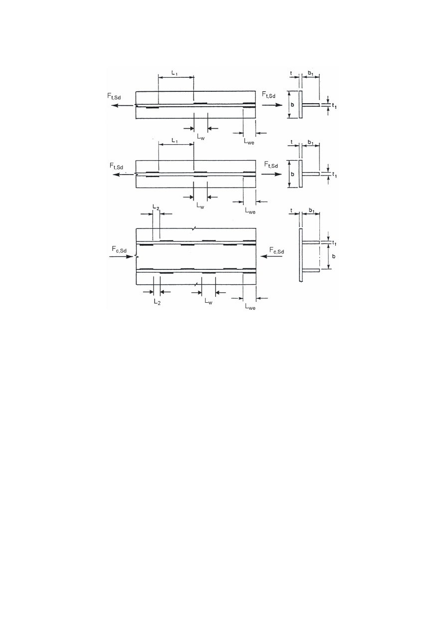
SU(1(
(4)
For eccentricity in single-sided partial penetration butt welds, see 4.12.
The larger of
/
we
0,75
E
and 0,75
E
1
For build-up members in tension:
The smallest of
/
1
16
W
and
16
W
1
and
200
mm
For build-up members in compression or shear:
The smallest of
/
2
12
W
and
12
W
1
and
0,25
E
and
200 mm
)LJXUH,QWHUPLWWHQWILOOHWZHOGV
3OXJZHOGV
(1)
Plug welds may be used:
–
to transmit shear,
–
to prevent the buckling or separation of lapped parts, and
–
to inter-connect the components of built-up members
but should not be used to resist externally applied tension.
(2)
The diameter of a circular hole, or width of an elongated hole, for a plug weld should be at least 8 mm
more than the thickness of the part containing it.
(3)
The ends of elongated holes should either be semi-circular or else should have corners which are
rounded to a radius of not less than the thickness of the part containing the slot, except for those ends
which extend to the edge of the part concerned.
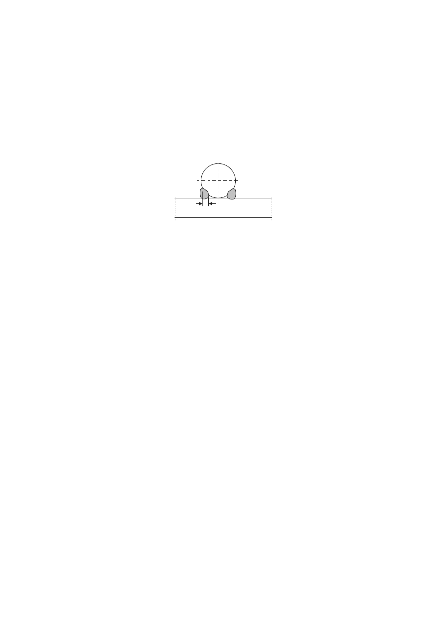
SU(1(
(4)
The thickness of a plug weld in parent material up to 16 mm thick should be equal to the thickness of
the parent material. The thickness of a plug weld in parent material over 16 mm thick should be at
least half the thickness of the parent material and not less than 16 mm.
(5)
The centre to centre spacing of plug welds should not exceed the value necessary to prevent local
buckling, see Table 3.3.
)ODUHJURRYHZHOGV
(1)
For solid bars the design throat thickness of flare groove welds, when fitted flush to the surface of the
solid section of the bars, is defined in Figure 4.2. The definition of the design throat thickness of flare
groove welds in rectangular hollow sections is given in 7.3.1(7).
a
)LJXUH(IIHFWLYHWKURDWWKLFNQHVVRIIODUHJURRYHZHOGVLQVROLGVHFWLRQV
:HOGVZLWKSDFNLQJV
(1)
In the case of welds with packing, the packing should be trimmed flush with the edge of the part that is
to be welded.
(2)
Where two parts connected by welding are separated by packing having a thickness less than the leg
length of weld necessary to transmit the force, the required leg length should be increased by the
thickness of the packing.
(3)
Where two parts connected by welding are separated by packing having a thickness equal to, or
greater than, the leg length of weld necessary to transmit the force, each of the parts should be
connected to the packing by a weld capable of transmitting the design force.
'HVLJQUHVLVWDQFHRIDILOOHWZHOG
/HQJWKRIZHOGV
(1)
The effective length of a fillet weld
O should be taken as the length over which the fillet is full-size.
This maybe taken as the overall length of the weld reduced by twice the effective throat thickness a.
Provided that the weld is full size throughout its length including starts and terminations, no reduction
in effective length need be made for either the start or the termination of the weld.
(2)
A fillet weld with an effective length less than 30 mm or less than 6 times its throat thickness,
whichever is larger, should not be designed to carry load.
(IIHFWLYHWKURDWWKLFNQHVV
(1)
The effective throat thickness, a, of a fillet weld should be taken as the height of the largest triangle
(with equal or unequal legs) that can be inscribed within the fusion faces and the weld surface,
measured perpendicular to the outer side of this triangle, see Figure 4.3.
(2)
The effective throat thickness of a fillet weld should not be less than 3 mm.
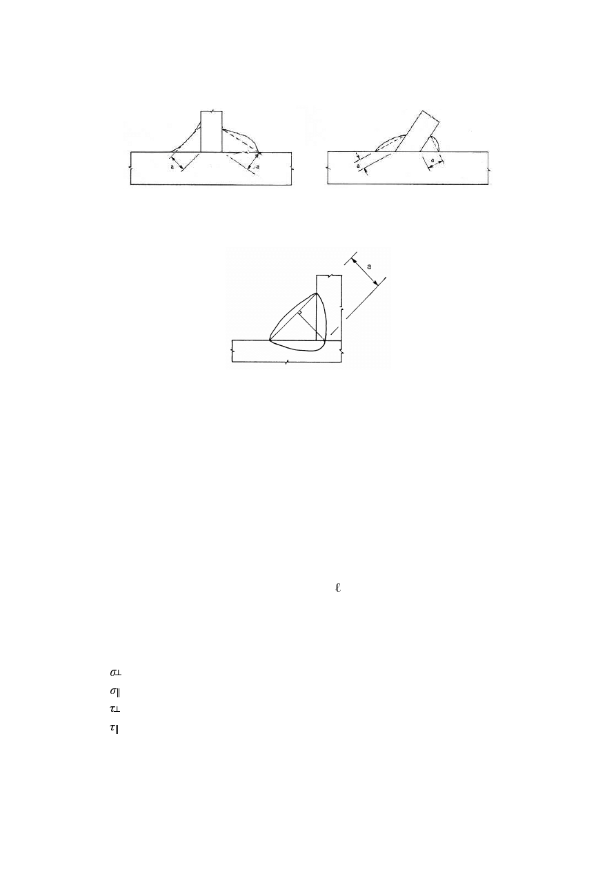
SU(1(
(3)
In determining the design resistance of a deep penetration fillet weld, account may be taken of its
additional throat thickness, see Figure 4.4, provided that preliminary tests show that the required
penetration can consistently be achieved.
)LJXUH7KURDWWKLFNQHVVRIDILOOHWZHOG
)LJXUH7KURDWWKLFNQHVVRIDGHHSSHQHWUDWLRQILOOHWZHOG
'HVLJQ5HVLVWDQFHRIILOOHWZHOGV
*HQHUDO
(1)
The design resistance of a fillet weld should be determined using either the Directional method given
in 4.5.3.2 or the Simplified method given in 4.5.3.3.
'LUHFWLRQDOPHWKRG
(1)
In this method, the forces transmitted by a unit length of weld are resolved into components parallel
and transverse to the longitudinal axis of the weld and normal and transverse to the plane of its throat.
(2)
The design throat area
$
w
should be taken as
$
w
=
D
eff
.
(3)
The location of the design throat area should be assumed to be concentrated in the root.
(4)
A uniform distribution of stress is assumed on the throat section of the weld, leading to the normal
stresses and shear stresses shown in Figure 4.5, as follows:
–
is the normal stress perpendicular to the throat
–
is the normal stress parallel to the axis of the weld
–
is the shear stress (in the plane of the throat) perpendicular to the axis of the weld
–
is the shear stress (in the plane of the throat) parallel to the axis of the weld.
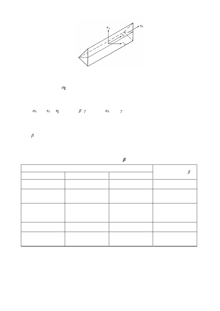
SU(1(
)LJXUH6WUHVVHVRQWKHWKURDWVHFWLRQRIDILOOHWZHOG
(5)
The normal stress
parallel to the axis is not considered when verifying the design resistance of the
weld.
(6)
The design resistance of the fillet weld will be sufficient if the following are both satisfied:
[
2
+ 3 (
2
+
2
)]
0,5
I
u
/ (
w
M2
) and
I
u
/
M2
...
(4.1)
where:
I
u
is
the nominal ultimate tensile strength of the weaker part joined;
w
is
the appropriate correlation factor taken from Table 4.1.
(7)
Welds between parts with different material strength grades should be designed using the properties of
the material with the lower strength grade.
7DEOH&RUUHODWLRQIDFWRU
w
IRUILOOHWZHOGV
Standard and steel grade
(1
(1
(1
Correlation factor
w
S 235
S 235 W
S 235 H
S 235 H
0,8
S 275
S 275 N/NL
S 275 M/ML
S 275 H
S 275 NH/NLH
S 275 H
S 275 NH/NLH
S 275 MH/MLH
0,85
S 355
S 355 N/NL
S 355 M/ML
S 355 W
S 355 H
S 355 NH/NLH
S 355 H
S 355 NH/NLH
S 355 MH/MLH
0,9
S 420 N/NL
S 420 M/ML
S 420 MH/MLH
1,0
S 460 N/NL
S 460 M/ML
S 460 Q/QL/QL1
S 460 NH/NLH
S 460 NH/NLH
S 460 MH/MLH
1,0
6LPSOLILHGPHWKRGIRUGHVLJQUHVLVWDQFHRIILOOHWZHOG
(1)
Alternatively to 4.5.3.2 the design resistance of a fillet weld may be assumed to be adequate if, at
every point along its length, the resultant of all the forces per unit length transmitted by the weld
satisfy the following criterion:
)
w,Ed
)
w,Rd
... (4.2)
SU(1(
where:
)
w,Ed
is the design value of the weld force per unit length;
)
w,
5d
is the design weld resistance per unit length.
(2)
Independent of the orientation of the weld throat plane to the applied force, the design resistance per
unit length F
w,Rd
should be determined from:
)
w,Rd
=
I
vw.d
a
... (4.3)
where:
I
vw.d
is the design shear strength of the weld.
(3)
The design shear strength
I
vw.d
of the weld should be determined from:
I
vw.d
=
2
3
/
0
Z
X
I
γ
β
...
(4.4)
where:
I
u
and
w
are defined in 4.5.3(7).
'HVLJQUHVLVWDQFHRIILOOHWZHOGVDOOURXQG
(1)
The design resistance of a fillet weld all round should be determined using one of the methods given in
4.5.
'HVLJQUHVLVWDQFHRIEXWWZHOGV
)XOOSHQHWUDWLRQEXWWZHOGV
(1)
The design resistance of a full penetration butt weld should be taken as equal to the design resistance
of the weaker of the parts connected, provided that the weld is made with a suitable consumable which
will produce all-weld tensile specimens having both a minimum yield strength and a minimum tensile
strength not less than those specified for the parent metal.
3DUWLDOSHQHWUDWLRQEXWWZHOGV
(1)
The design resistance of a partial penetration butt weld should be determined using the method for a
deep penetration fillet weld given in 4.5.2(3).
(2) The throat thickness of a partial penetration butt weld should not be greater than the depth of
penetration that can be consistently achieved, see 4.5.2(3).
7EXWWMRLQWV
(1)
The design resistance of a T-butt joint, consisting of a pair of partial penetration butt welds reinforced
by superimposed fillet welds, may be determined as for a full penetration butt weld (see 4.7.1) if the
total nominal throat thickness, exclusive of the unwelded gap, is not less than the thickness t of the
part forming the stem of the tee joint, provided that the unwelded gap is not more than (
W / 5) or 3 mm,
whichever is less, see Figure 4.6(a).
(2)
The design resistance of a T-butt joint which does not meet the requirements given in 4.7.3(1) should
be determined using the method for a fillet weld or a deep penetration fillet weld given in 4.5
depending on the amount of penetration. The throat thickness should be determined in conformity with
the provisions for both fillet welds (see 4.5.2) and partial penetration butt welds (see 4.7.2).
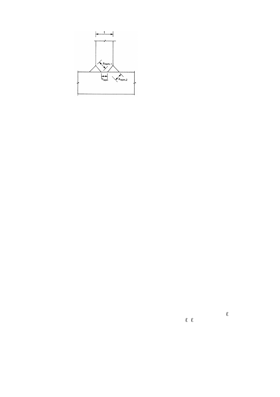
SU(1(
D
nom,1
+
D
nom,2
W
The smaller of
F
nom
W
/5 and 3 mm
)LJXUH(IIHFWLYHIXOOSHQHWUDWLRQRI7EXWWZHOGV
'HVLJQUHVLVWDQFHRISOXJZHOGV
(1)
The design resistance
)
w,Rd
of a plug weld (see 4.3.5) should be taken as:
)
w,Rd
= f
vw,d
A
w
,
... (4.5)
where
f
vw.d
is the design shear strength of a weld given in 4.5.3.3(4).
A
w
is the design throat area and should be taken as the area of the hole.
'LVWULEXWLRQRIIRUFHV
(1)
The distribution of forces in a welded connection may be calculated on the assumption of either elastic
or plastic behaviour in conformity with 2.4 and 2.5.
(2)
It is acceptable to assume a simplified load distribution within the welds.
(3)
Residual stresses and stresses not subjected to transfer of load need not be included when checking the
resistance of a weld. This applies specifically to the normal stress parallel to the axis of a weld.
(4)
Welded joints should be designed to have adequate deformation capacity. However, ductility of the
welds should not be relied upon.
(5)
In joints where plastic hinges may form, the welds should be designed to provide at least the same
design resistance as the weakest of the connected parts.
(6)
In other joints where deformation capacity for joint rotation is required due to the possibility of
excessive straining, the welds require sufficient strength not to rupture before general yielding in the
adjacent parent material.
(7)
If the design resistance of an intermittent weld is determined by using the total length
tot
, the weld
shear force per unit length
)
w,Ed
should be multiplied by the factor (
H+ VHHFigure 4.7.
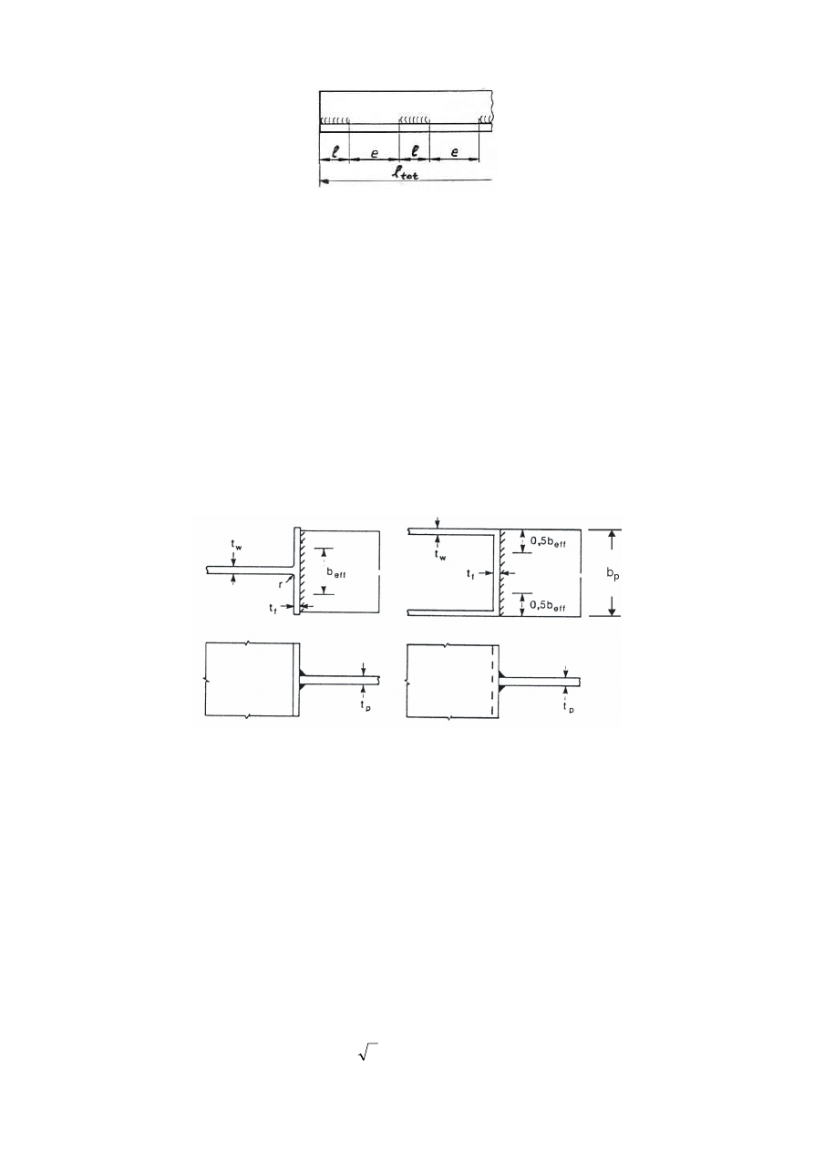
SU(1(
)LJXUH&DOFXODWLRQRIZHOGIRUFHVIRULQWHUPLWWHQWZHOGV
&RQQHFWLRQVWRXQVWLIIHQHGIODQJHV
(1)
Where a transverse plate (or beam flange) is welded to a supporting unstiffened flange of an I, H or
other section, see Figure 4.8, and provided that the condition given in 4.10(3) is met, the applied force
perpendicular to the unstiffened flange should not exceed any of the relevant design resistances as
follows:
–
that of the web of the supporting member of I or H sections as given in 6.2.6.2 or 6.2.6.3 as
appropriate,
–
those for a transverse plate on a RHS member as given in Table 7.13,
–
that of the supporting flange as given by formula (6.20) in 6.2.6.4.3(1) calculated assuming the
applied force is concentrated over an effective width,
E
eff
, of the flange as given in 4.10(2) or
4.10(4) as relevant.”
)LJXUH(IIHFWLYHZLGWKRIDQXQVWLIIHQHG7MRLQW
(2)
For an unstiffened I or H section the effective width
E
eff
should be obtained from:
E
eff
=
I
Z
NW
V
W
7
2
+
+
... (4.6a)
where:
N =
)
/
(
)
/
(
,
,
S
\
I
\
S
I
I
I
W
W
but
N ...
(4.6b)
I
y,f
is
the yield strength of the flange of the I or H section;
I
y,p
is
the yield strength of the plate welded to the I or H section.
The dimension
V should be obtained from:
–
for a rolled I or H section:
V= U
...
(4.6c)
–
for a welded I or H section:
V=
D
2
...
(4.6d)
SU(1(
(3)
For an unstiffened flange of an I or H section , the following criterion should be satisfied:
E
eff
S
S
X
S
\
E
I
I
)
/
(
,
,
...
(4.7)
where:
I
u,p
is
the ultimate strength of the plate welded to the I or H section.
b
p
is
the width of the plate welded to the I or H section.
Otherwise the joint should be stiffened.
(4)
For other sections such as box sections or channel sections where the width of the connected plate is
similar to the width of the flange, the effective width
E
eff
should be obtained from:
E
eff
= 2
W
w
+ 5
W
f
but
E
eff
W
w
+ 5
NW
f
...
(4.8)
127(For hollow sections, see Table 7.13.
(5)
Even if
E
eff
E
p
, the welds connecting the plate to the flange need to be designed to transmit the
design resistance of the plate
E
P
W
P
I
y,P
M0
assuming a uniform stress distribution.
/RQJMRLQWV
(1)
In lap joints the design resistance of a fillet weld should be reduced by multiplying it by a reduction
factor
Lw
to allow for the effects of non-uniform distribution of stress along its length.
(2)
The provisions given in 4.11 do not apply when the stress distribution along the weld corresponds to
the stress distribution in the adjacent base metal, as, for example, in the case of a weld connecting the
flange and the web of a plate girder.
(3)
Generally in lap joints longer than 150
D the reduction factor
Lw
should be taken as
Lw.1
given by:
Lw.1
= 1,2
í/
j
/(150
D) but
Lw.1
... (4.9)
where:
/
j
is
the overall length of the lap in the direction of the force transfer.
(4) For fillet welds longer than 1,7 metres connecting transverse stiffeners in plated members, the
reduction factor
Lw
may be taken as
Lw.2
given by:
Lw.2
= 1,1
í/
w
/17 but
Lw.2
DQG
Lw.2
...
(4.10)
where:
/
w
is
the length of the weld (in metres).
(FFHQWULFDOO\ORDGHGVLQJOHILOOHWRUVLQJOHVLGHGSDUWLDOSHQHWUDWLRQEXWWZHOGV
(1)
Local eccentricity should be avoided whenever it is possible.
(2)
Local eccentricity (relative to the line of action of the force to be resisted) should be taken into account
in the following cases:
–
Where a bending moment transmitted about the longitudinal axis of the weld produces tension at
the root of the weld, see Figure 4.9(a);
–
Where a tensile force transmitted perpendicular to the longitudinal axis of the weld produces a
bending moment, resulting in a tension force at the root of the weld, see Figure 4.9(b).
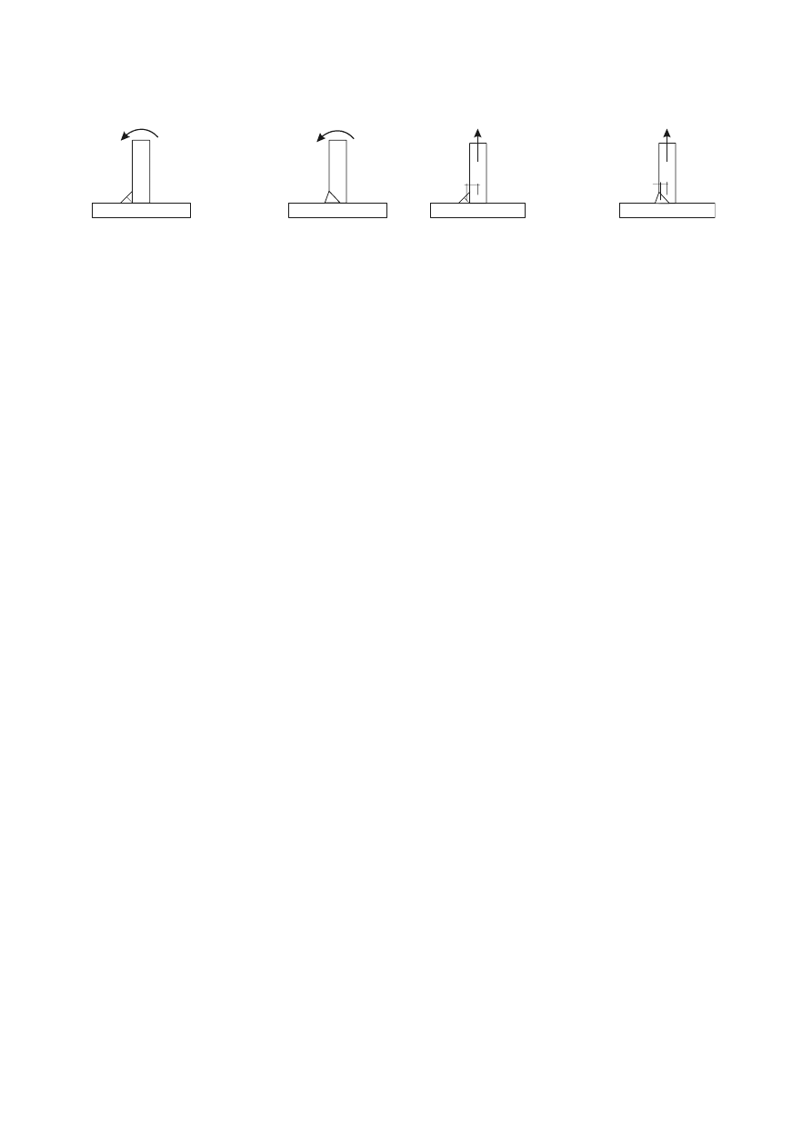
SU(1(
(3)
Local eccentricity need not be taken into account if a weld is used as part of a weld group around the
perimeter of a structural hollow section.
e
e
(a)
Bending moment produces tension at the
root of the weld
(b)
Tensile force produces tension at the root of
the weld
)LJXUH6LQJOHILOOHWZHOGVDQGVLQJOHVLGHGSDUWLDOSHQHWUDWLRQEXWWZHOGV
$QJOHVFRQQHFWHGE\RQHOHJ
(1)
In angles connected by one leg, the eccentricity of welded lap joint end connections may be allowed
for by adopting an effective cross-sectional area and then treating the member as concentrically
loaded.
(2)
For an equal-leg angle, or an unequal-leg angle connected by its larger leg, the effective area may be
taken as equal to the gross area.
(3)
For an unequal-leg angle connected by its smaller leg, the effective area should be taken as equal to
the gross cross-sectional area of an equivalent equal-leg angle of leg size equal to that of the smaller
leg, when determining the design resistance of the cross-section, see EN 1993-1-1. However when
determining the design buckling resistance of a compression member, see EN 1993-1-1, the actual
gross cross-sectional area should be used.
:HOGLQJLQFROGIRUPHG]RQHV
(1)
Welding may be carried out within a length 5t either side of a cold-formed zone, see Table 4.2,
provided that one of the following conditions is fulfilled:
–
the cold-formed zones are normalized after cold-forming but before welding;
–
the
U/W-ratio satisfy the relevant value obtained from Table 4.2.
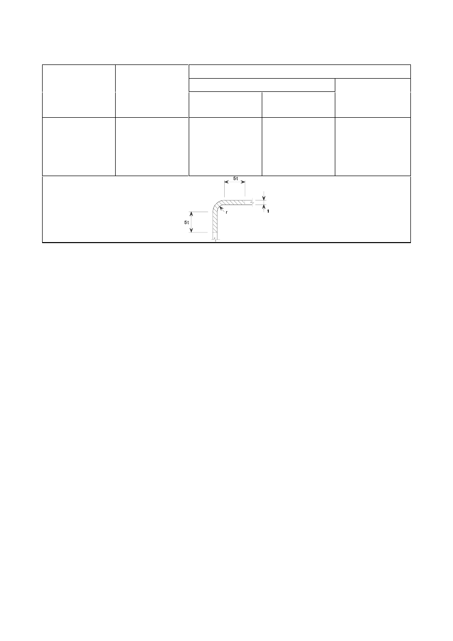
SU(1(
7DEOH&RQGLWLRQVIRUZHOGLQJFROGIRUPHG]RQHVDQGDGMDFHQWPDWHULDO
Maximum thickness (mm)
Generally
r/t
Strain due to cold
forming (%)
Predominantly
static loading
Where fatigue
predominates
Fully killed
Aluminium-killed
steel
(Al
any
any
24
12
8
4
any
16
12
10
8
4
any
any
24
12
10
6

SU(1(
$QDO\VLVFODVVLILFDWLRQDQGPRGHOOLQJ
*OREDODQDO\VLV
*HQHUDO
(1)
The effects of the behaviour of the joints on the distribution of internal forces and moments within a
structure, and on the overall deformations of the structure, should generally be taken into account, but
where these effects are sufficiently small they may be neglected.
(2)
To identify whether the effects of joint behaviour on the analysis need be taken into account, a
distinction may be made between three simplified joint models as follows:
–
simple, in which the joint may be assumed not to transmit bending moments;
–
continuous, in which the behaviour of the joint may be assumed to have no effect on the analysis;
–
semi-continuous, in which the behaviour of the joint needs to be taken into account in the
analysis.
(3) The appropriate type of joint model should be determined from Table 5.1, depending on the
classification of the joint and on the chosen method of analysis.
(4) The design moment-rotation characteristic of a joint used in the analysis may be simplified by
adopting any appropriate curve, including a linearised approximation (e.g. bi-linear or tri-linear),
provided that the approximate curve lies wholly below the design moment-rotation characteristic.
7DEOH7\SHRIMRLQWPRGHO
Method of global
analysis
Classification of joint
Elastic
Nominally pinned
Rigid
Semi-rigid
Rigid-Plastic
Nominally pinned
Full-strength
Partial-strength
Elastic-Plastic
Nominally pinned
Rigid and full-strength
Semi-rigid and partial-strength
Semi-rigid and full-strength
Rigid and partial-strength
Type of
joint model
Simple
Continuous
Semi-continuous
(ODVWLFJOREDODQDO\VLV
(1)
The joints should be classified according to their rotational stiffness, see 5.2.2.
(2)
The joints shall have sufficient strength to transmit the forces and moments acting at the joints
resulting from the analysis.
(3)
In the case of a semi-rigid joint, the rotational stiffness
6
j
corresponding to the bending moment
0
j,Ed
should generally be used in the analysis. If
0
j,Ed
does not exceed 2/3
0
j,Rd
the initial rotational
stiffness
6
j,ini
may be taken in the global analysis, see Figure 5.1(a).
(4)
As a simplification to 5.1.2(3), the rotational stiffness may be taken as
6
j,ini
/ in the analysis, for all
values of the moment
0
j,Ed
, as shown in Figure 5.1(b), where is the stiffness modification
coefficient from Table 5.2.
(5)
For joints connecting H or I sections
6
j
is given in 6.3.1.
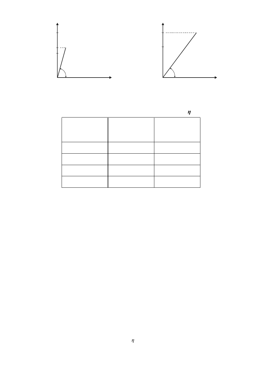
SU(1(
M
j
φ
M
j,Ed
M
j,Rd
2/3 M
j,Rd
S
j,ini
M
j
φ
M
j,Ed
M
j,Rd
S
j,ini
/
η
a)
0
j,Ed
2/3
0
j,Rd
b)
0
j,Ed
0
j,Rd
)LJXUH5RWDWLRQDOVWLIIQHVVWREHXVHGLQHODVWLFJOREDODQDO\VLV
7DEOH6WLIIQHVVPRGLILFDWLRQFRHIILFLHQW
Type of connection
Beam-to-column
joints
Other types of joints
(beam-to-beam
joints, beam splices,
column base joints)
Welded
2
3
Bolted end-plate
2
3
Bolted flange cleats
2
3,5
Base plates
-
3
5LJLGSODVWLFJOREDODQDO\VLV
(1)
The joints should be classified according to their strength, see 5.2.3.
(2)
For joints connecting H or I sections
0
j,Rd
is given in 6.2.
(3)
For joints connecting hollow sections the method given in section 7 may be used.
(4)
The rotation capacity of a joint shall be sufficient to accommodate the rotations resulting from the
analysis.
(5)
For joints connecting H or I sections the rotation capacity should be checked according to 6.4.
(ODVWLFSODVWLFJOREDODQDO\VLV
(1)
The joints should be classified according to both stiffness (see 5.2.2) and strength (see 5.2.3).
(2)
For joints connecting H or I sections
0
j,Rd
is given in 6.2,
6
j
is given in 6.3.1 and
φ
Cd
is given in 6.4.
(3)
For joints connecting hollow sections the method given in section 7 may be used.
(4)
The moment rotation characteristic of the joints should be used to determine the distribution of
internal forces and moments.
(5)
As a simplification, the bi-linear design moment-rotation characteristic shown in Figure 5.2 may be
adopted. The stiffness modification coefficient should be obtained from Table 5.2.
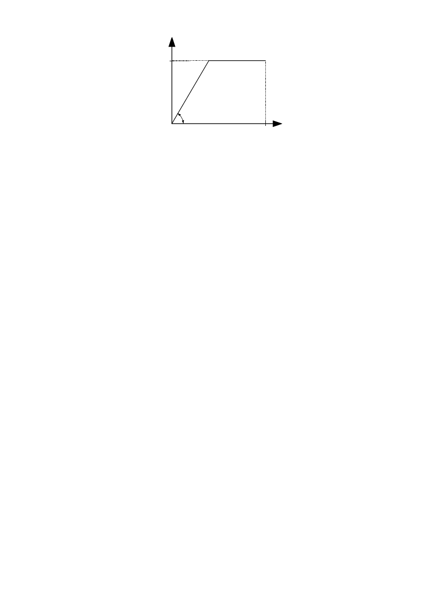
SU(1(
S /
j,ini
M
j
M
j,Rd
1
Cd
)LJXUH6LPSOLILHGELOLQHDUGHVLJQPRPHQWURWDWLRQFKDUDFWHULVWLF
*OREDODQDO\VLVRIODWWLFHJLUGHUV
(1)
The provisions given in 5.1.5 apply only to structures whose joints are verified according to section 7.
(2)
The distribution of axial forces in a lattice girder may be determined on the assumption that the
members are connected by pinned joints (see also 2.7).
(3)
Secondary moments at the joints, caused by the rotational stiffnesses of the joints, may be neglected
both in the design of the members and in the design of the joints, provided that both of the following
conditions are satisfied:
–
the joint geometry is within the range of validity specified in Table 7.1, Table 7.8, Table 7.9 or
Table 7.20 as appropriate;
–
the ratio of the system length to the depth of the member in the plane of the lattice girder is not
less than the appropriate minimum value. For building structures, the appropriate minimum value
may be assumed to be 6. Larger values may apply in other parts of EN 1993.
(4)
The moments resulting from transverse loads (whether in-plane or out-of-plane) that are applied
between panel points, should be taken into account in the design of the members to which they are
applied. Provided that the conditions given in 5.1.5(3) are satisfied:
–
the brace members may be considered as pin-connected to the chords, so moments resulting from
transverse loads applied to chord members need not be distributed into brace members, and vice
versa;
–
the chords may be considered as continuous beams, with simple supports at panel points.
(5)
Moments resulting from eccentricities may be neglected in the design of tension chord members and
brace members. They may also be neglected in the design of connections if the eccentricities are
within the following limits:
–
íG
0
H G
0
...
(5.1a)
–
íK
0
H K
0
...
(5.1b)
where:
H is the eccentricity defined in Figure 5.3;
G
0
is
the diameter of the chord;
K
0
is
the depth of the chord, in the plane of the lattice girder.
(6) When the eccentricities are within the limits given in 5.1.5(5), the moments resulting from the
eccentricities should be taken into account in the design of compression chord members. In this case
the moments produced by the eccentricity should be distributed between the compression chord
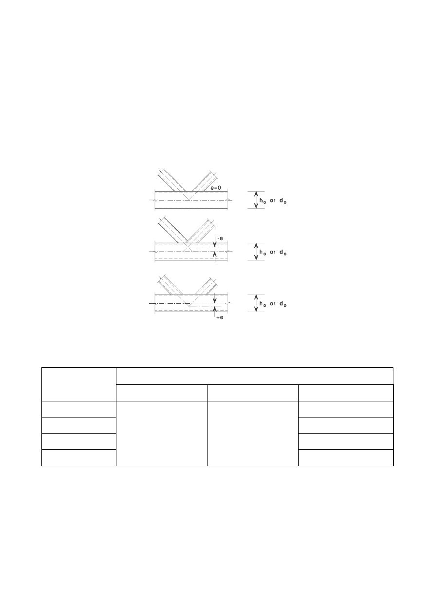
SU(1(
members on each side of the joint, on the basis of their relative stiffness coefficients
,/
, where
/ is
the system length of the member, measured between panel points.
(7)
When the eccentricities are outside the limits given in 5.1.5(5), the moments resulting from the
eccentricities should be taken into account in the design of the connections and the compression chord
members. In this case the moments produced by the eccentricity should be distributed between all the
members meeting at the joint, on the basis of their relative stiffness coefficients
,/
.
(8)
The stresses in a chord resulting from moments taken into account in the design of the chord, should
also be taken into account in determining the factors
N
m
,
N
n
and
N
p
used in the design of the
connections, see Table 7.2 to Table 7.5, Table 7.10 and Table 7.12 to Table 7.14.
(9)
The cases where moments should be taken into account are summarized in Table 5.3.
)LJXUH(FFHQWULFLW\RIMRLQWV
7DEOH $OORZDQFHIRUEHQGLQJPRPHQWV
Source of the bending moment
Type of component
Secondary effects
Transverse loading
Eccentricity
Compression chord
Yes
Tension chord
No
Brace member
No
Connection
Not if 5.1.5(3)
is satisfied
Yes
Not if 5.1.5(5) is satisfied

SU(1(
&ODVVLILFDWLRQRIMRLQWV
*HQHUDO
(1)
The details of all joints shall fulfil the assumptions made in the relevant design method, without
adversely affecting any other part of the structure.
(2)
Joints may be classified by their stiffness (see 5.2.2) and by their strength (see 5.2.3).
&ODVVLILFDWLRQE\VWLIIQHVV
*HQHUDO
(1)
A joint may be classified as rigid, nominally pinned or semi-rigid according to its rotational stiffness,
by comparing its initial rotational stiffness
6
j,ini
with the classification boundaries given in 5.2.2.5.
127(Rules for the determination of 6
j,ini
for joints connecting H or I sections are given in 6.3.1.
Rules for the determination of
6
j,ini
for joints connecting hollow sections are not given in this
Standard.
(2)
A joint may be classified on the basis of experimental evidence, experience of previous satisfactory
performance in similar cases or by calculations based on test evidence.
1RPLQDOO\SLQQHGMRLQWV
(1)
A nominally pinned joint shall be capable of transmitting the internal forces, without developing
significant moments which might adversely affect the members or the structure as a whole.
(2)
A nominally pinned joint shall be capable of accepting the resulting rotations under the design loads.
5LJLGMRLQWV
(1)
Joints classified as rigid may be assumed to have sufficient rotational stiffness to justify analysis based
on full continuity.
6HPLULJLGMRLQWV
(1)
A joint which does not meet the criteria for a rigid joint or a nominally pinned joint should be
classified as a semi-rigid joint.
127(Semi-rigid joints provide a predictable degree of interaction between members, based on the
design moment-rotation characteristics of the joints.
(2)
Semi-rigid joints should be capable of transmitting the internal forces and moments.
&ODVVLILFDWLRQERXQGDULHV
(1)
Classification boundaries for joints other than column bases are given in 5.2.2.1(1) and Figure 5.4.
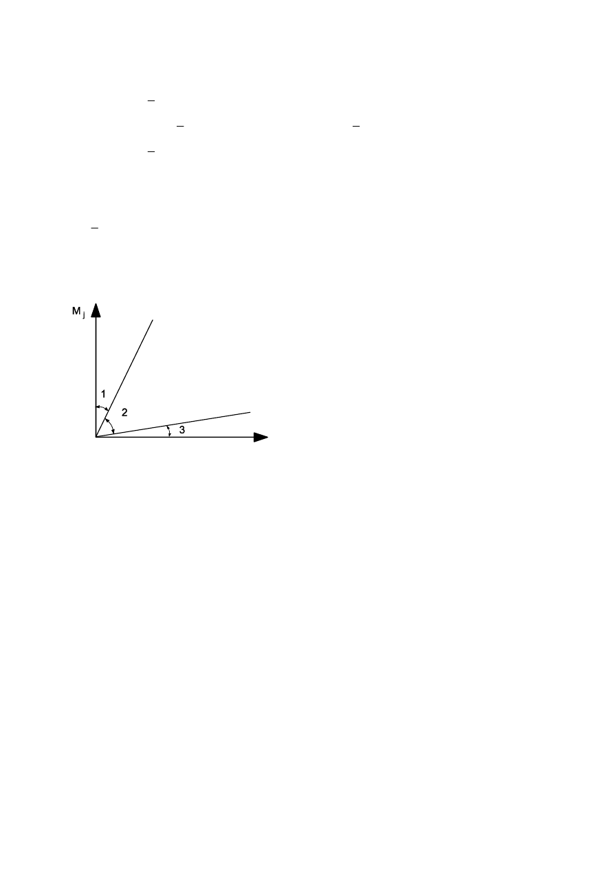
SU(1(
(2)
Column bases may be classified as rigid provided the following conditions are satisfied:
–
in frames where the bracing system reduces the horizontal displacement by at least 80 % and
where the effects of deformation may be neglected
–
if
0
λ
...
(5.2a)
–
if 0,5 <
0
λ
< 3,93
and
6
j,ini
0
λ
- 1 )
(,
c
/
/
c
; ...
(5.2b)
–
if
0
λ
and
6
j,ini
(,
c
/
/
c
. ...
(5.2c)
–
otherwise if
6
j,ini
(,
c
/
/
c
. ...
(5.2d)
where:
0
λ
is the slenderness of a column in which both ends are assumed to be pinned;
,
c
,
/
c
are as given in Figure 5.4.
φ
Zone 1: rigid, if
6
j,ini
N
b
(,
b
/
/
b
where
N
b
= 8 for frames where the bracing system
reduces the horizontal displacement by
at least 80 %
N
b
= 25 for other frames,
provided that in every
storey
.
b
/
.
c
0,1
*)
Zone 2: semi-rigid
All joints in zone 2 should be classified as
semi-rigid. Joints in zones 1 or 3 may
optionally also be treated as semi-rigid.
Zone 3: nominally pinned, if
6
j,ini
(,
b
/
/
b
*)
For frames where
.
b
/
.
c
< 0,1 the joints
should be classified as semi-rigid.
Key:
.
b
is the mean value of
,
b
/
/
b
for all the beams at the top of that storey;
.
c
is the mean value of
,
c
/
/
c
for all the columns in that storey;
,
b
is the second moment of area of a beam;
,
c
is the second moment of area of a column;
/
b
is the span of a beam (centre-to-centre of columns);
/
c
is the storey height of a column.
)LJXUH&ODVVLILFDWLRQRIMRLQWVE\VWLIIQHVV
&ODVVLILFDWLRQE\VWUHQJWK
*HQHUDO
(1)
A joint may be classified as full-strength, nominally pinned or partial strength by comparing its design
moment resistance
0
j,Rd
with the design moment resistances of the members that it connects. When
classifying joints, the design resistance of a member should be taken as that member adjacent to the
joint.
1RPLQDOO\SLQQHGMRLQWV
(1)
A nominally pinned joint shall be capable of transmitting the internal forces, without developing
significant moments which might adversely affect the members or the structure as a whole.
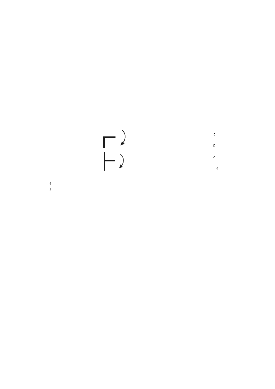
SU(1(
(2)
A nominally pinned joint shall be capable of accepting the resulting rotations under the design loads.
(3)
A joint may be classified as nominally pinned if its design moment resistance
0
j,Rd
is not greater than
0,25 times the design moment resistance required for a full-strength joint, provided that it also has
sufficient rotation capacity.
)XOOVWUHQJWKMRLQWV
(1)
The design resistance of a full strength joint shall be not less than that of the connected members.
(2)
A joint may be classified as full-strength if it meets the criteria given in Figure 5.5.
3DUWLDOVWUHQJWKMRLQWV
(1)
A joint which does not meet the criteria for a full-strength joint or a nominally pinned joint should be
classified as a partial-strength joint.
a) Top of column
M
j,Sd
Either
0
j,Rd
0
b,p
5G
or
0
j,Rd
0
c,p
5G
b) Within column height
M
j,Sd
Either
0
j,Rd
0
b,p
5G
or
0
j,Rd
0
c,p
5G
Key:
0
b,p
5G
is the design plastic moment resistance of a beam;
0
c,p
5G
is the design plastic moment resistance of a column.
)LJXUH)XOOVWUHQJWKMRLQWV
0RGHOOLQJRIEHDPWRFROXPQMRLQWV
(1)
To model the deformational behaviour of a joint, account should be taken of the shear deformation of
the web panel and the rotational deformation of the connections.
(2)
Joint configurations should be designed to resist the internal bending moments
0
b1,Ed
and
0
b2,Ed
,
normal forces
1
b1,Ed
and
1
b2,Ed
and shear forces
9
b1,Ed
and
9
b2,Ed
applied to the connections by the
connected members, see Figure 5.6.
(3)
The resulting shear force
9
wp,Ed
in the web panel should be obtained using:
9
wp,Ed
= (
0
b1,Ed
í0
b2,Ed
)/z
í9
c1,Ed
í9
c2,Ed
)/2 ...
(5.3)
where:
] is the lever arm, see 6.2.7.
(4)
To model a joint in a way that closely reproduces the expected behaviour, the web panel in shear and
each of the connections should be modelled separately, taking account of the internal moments and
forces in the members, acting at the periphery of the web panel, see Figure 5.6(a) and Figure 5.7.
(5)
As a simplified alternative to 5.3(4), a single-sided joint configuration may be modelled as a single
joint, and a double-sided joint configuration may be modelled as two separate but inter-acting joints,
one on each side. As a consequence a double-sided beam-to-column joint configuration has two
moment-rotation characteristics, one for the right-hand joint and another for the left-hand joint.
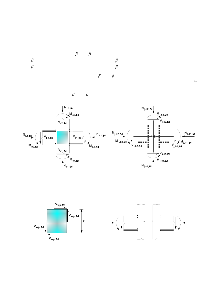
SU(1(
(6)
In a double-sided, beam-to-column joint each joint should be modelled as a separate rotational spring,
as shown in Figure 5.8, in which each spring has a moment-rotation characteristic that takes into
account the behaviour of the web panel in shear as well as the influence of the relevant connection.
(7)
When determining the design moment resistance and rotational stiffness for each of the joints, the
possible influence of the web panel in shear should be taken into account by means of the
transformation parameters
1
and
2
, where:
1
is
the value of the transformation parameter for the right-hand side joint;
2
is
the value of the transformation parameter for the left-hand side joint.
127(The transformation parameters
1
and
2
are used directly in 6.2.7.2(7) and 6.3.2(1). They
are also used in 6.2.6.2(4) and 6.2.6.3(4) in connection with Table 6.3 to obtain the reduction factor
for shear.
(8)
Approximate values for
1
and
2
based on the values of the beam moments
0
b1,Ed
and
0
b2,Ed
at
the periphery of the web panel, see Figure 5.6(a), may be obtained from Table 5.4.
a) Values at periphery of web panel
b) Values at intersection of member centrelines
Direction of forces and moments are considered as positive in relation to equations (5.3) and (5.4)
)LJXUH)RUFHVDQGPRPHQWVDFWLQJRQWKHMRLQW
M
b2,Ed
N
b2,Ed
V
b2,Ed
V
b1,Ed
M
b1,Ed
N
b1,Ed
a) Shear forces in web panel
b) Connections, with forces and moments in beams
)LJXUH)RUFHVDQGPRPHQWVDFWLQJRQWKHZHESDQHODWWKHFRQQHFWLRQV
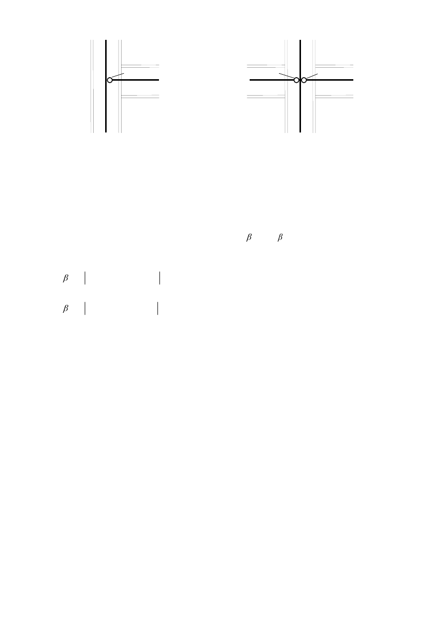
SU(1(
[ [
[
3
2
1
Single-sided joint configuration
Double-sided joint configuration
-RLQW
-RLQWOHIWVLGH
-RLQWULJKWVLGH
)LJXUH0RGHOOLQJWKHMRLQW
(9)
As an alternative to 5.3(8), more accurate values of
1
and
2
based on the values of the beam
moments
0
j,b1,Ed
and
0
j,b2,Ed
at the intersection of the member centrelines, may be determined from
the simplified model shown in Figure 5.6(b) as follows:
1
=
(G
E
M
(G
E
M
0
0
,
1
,
,
2
,
/
1
−
...
(5.4a)
2
=
(G
E
M
(G
E
M
0
0
,
2
,
,
1
,
/
1
−
...
(5.4b)
where:
0
j,b1,Ed
is the moment at the intersection from the right hand beam;
0
j,b2,Ed
is the moment at the intersection from the left hand beam.
(10) In the case of an unstiffened double-sided beam-to-column joint configuration in which the depths of
the two beams are not equal, the actual distribution of shear stresses in the column web panel should
be taken into account when determining the design moment resistance.
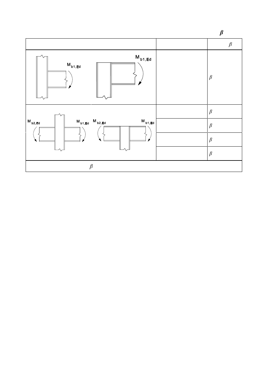
SU(1(
7DEOH$SSUR[LPDWHYDOXHVIRUWKHWUDQVIRUPDWLRQSDUDPHWHU
Type of joint configuration
Action
Value of
0
b1,Ed
§
0
b1,Ed
=
0
b2,Ed
= 0 *)
0
b1,Ed
/
0
b2,Ed
> 0
§
0
b1,Ed
/
0
b2,Ed
< 0
§
0
b1,Ed
+
0
b2,Ed
= 0
§
*
)
In this case the value of is the exact value rather than an approximation.

SU(1(
6WUXFWXUDOMRLQWVFRQQHFWLQJ+RU,VHFWLRQV
*HQHUDO
%DVLV
(1)
This section contains design methods to determine the structural properties of joints in frames of any
type. To apply these methods, a joint should be modelled as an assembly of basic components, see
1.3(1).
(2)
The basic components used in this Standard are identified in Table 6.1 and their properties should be
determined in accordance with the provisions given in this Standard. Other basic components may be
used provided their properties are based on tests or analytical and numerical methods supported by
tests, see EN 1990.
127(The design methods for basic joint components given in this Standard are of general
application and can also be applied to similar components in other joint configurations. However the
specific design methods given for determining the design moment resistance, rotational stiffness and
rotation capacity of a joint are based on an assumed distribution of internal forces for joint
configurations indicated in Figure 1.2. For other joint configurations, design methods for determining
the design moment resistance, rotational stiffness and rotation capacity should be based on appropriate
assumptions for the distribution of internal forces.
6WUXFWXUDOSURSHUWLHV
'HVLJQPRPHQWURWDWLRQFKDUDFWHULVWLF
(1)
A joint may be represented by a rotational spring connecting the centre lines of the connected
members at the point of intersection, as indicated in Figure 6.1(a) and (b) for a single-sided beam-to-
column joint configuration. The properties of the spring can be expressed in the form of a design
moment-rotation characteristic that describes the relationship between the bending moment
0
j,Ed
applied to a joint and the corresponding rotation
φ
Ed
between the connected members. Generally the
design moment-rotation characteristic is non-linear as indicated in Figure 6.1(c).
(2)
A design moment-rotation characteristic, see Figure 6.1(c) should define the following three main
structural properties:
–
moment resistance;
–
rotational stiffness;
–
rotation capacity.
127(In certain cases the actual moment-rotation behaviour of a joint includes some rotation due to
such effects as bolt slip, lack of fit and, in the case of column bases, foundation-soil interactions. This
can result in a significant amount of initial hinge rotation that may need to be included in the design
moment-rotation characteristic.
(3)
The design moment-rotation characteristics of a beam-to-column joint shall be consistent with the
assumptions made in the global analysis of the structure and with the assumptions made in the design
of the members, see EN 1993-1-1.
(4)
The design moment-rotation characteristic for joints and column bases of I and H sections as obtained
from 6.3.1(4) may be assumed to satisfy the requirements of 5.1.1(4) for simplifying this characteristic
for global analysis purposes.
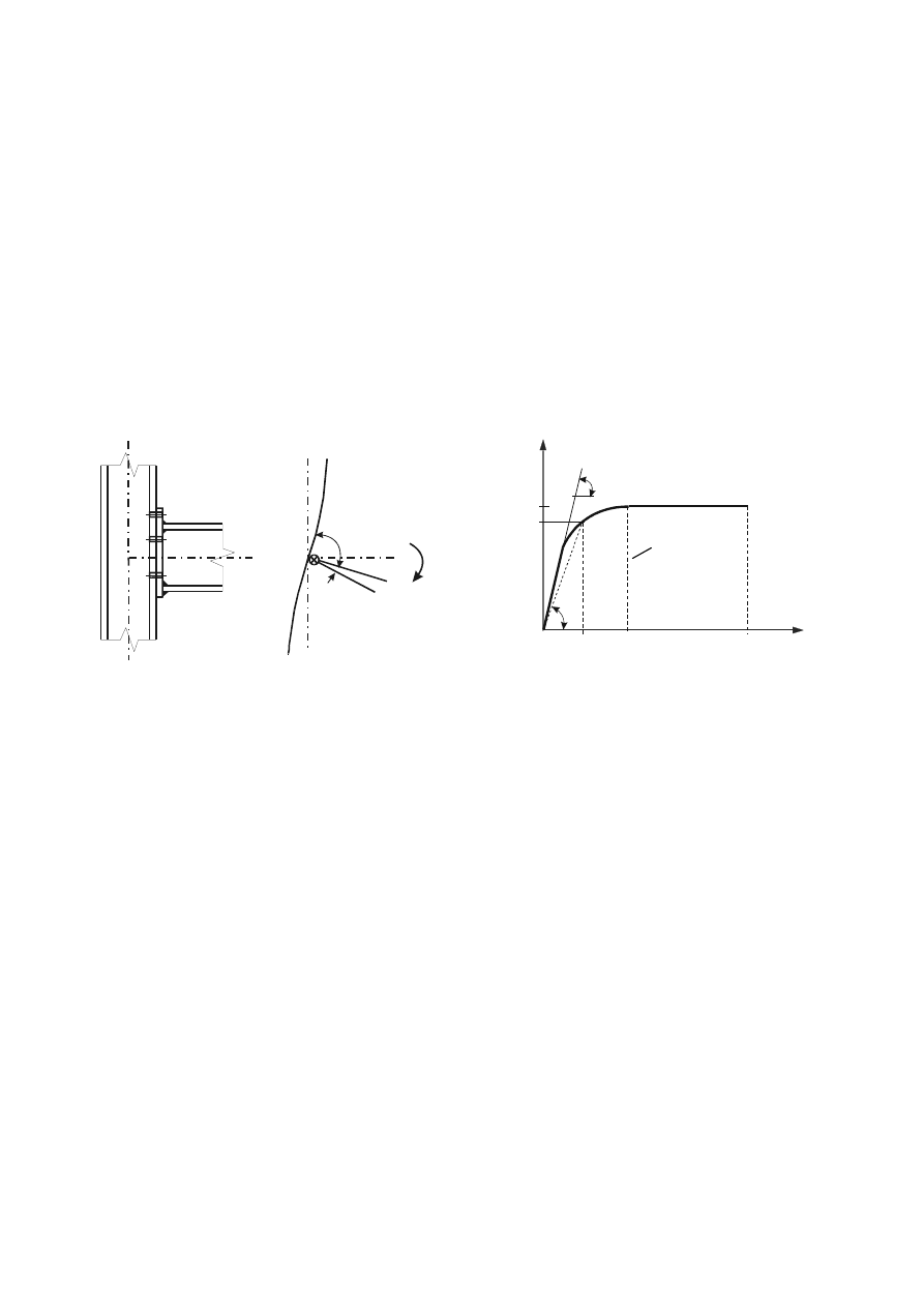
SU(1(
'HVLJQ0RPHQWUHVLVWDQFH
(1) The design moment resistance
0
j,Rd
, which is equal to the maximum moment of the design
moment-rotation characteristic, see Figure 6.1(c), should be taken as that given by 6.1.3(4)
5RWDWLRQDOVWLIIQHVV
(1)
The rotational stiffness S
j
, which is the secant stiffness as indicated in Figure 6.1(c), should be taken as
that given by 5.1.1(4). For a design moment-rotation characteristic this definition of
6
j
applies up to
the rotation
φ
Xd
at which
0
j,Ed
first reaches
0
j,Rd
, but not for larger rotations, see Figure 6.1(c). The
initial rotational stiffness
6
j,ini
, which is the slope of the elastic range of the design moment-rotation
characteristic, should be taken as that given by 6.1.3(4).
5RWDWLRQFDSDFLW\
(1)
The design rotation capacity
φ
Cd
of a joint, which is equal to the maximum rotation of the design
moment-rotation characteristic, see Figure 6.1(c), should be taken as that given by 6.1.3(4).
M
φ
j,Ed
Ed
90°
1
M
M
M
S
S
j
j,Rd
J,Ed
j,ini
j
φ
φ
φ
φ
Ed
Xd
Cd
/LPLWIRU6
M
a) Joint
b) Model
c) Design moment-rotation characteristic
)LJXUH'HVLJQPRPHQWURWDWLRQFKDUDFWHULVWLFIRUDMRLQW
%DVLFFRPSRQHQWVRIDMRLQW
(1)
The design moment-rotation characteristic of a joint should depend on the properties of its basic
components, which should be among those identified in 6.1.3(2).
(2)
The basic joint components should be those identified in Table 6.1, together with the reference to the
application rules which should be used for the evaluation of their structural properties.
(3)
Certain joint components may be reinforced. Details of the different methods of reinforcement are
given in 6.2.4.3 and 6.2.6.
(4) The relationships between the properties of the basic components of a joint and the structural
properties of the joint should be those given in the following clauses:
–
for moment resistance in 6.2.7 and 6.2.8;
–
for rotational stiffness in 6.3.1;
–
for rotation capacity in 6.4.
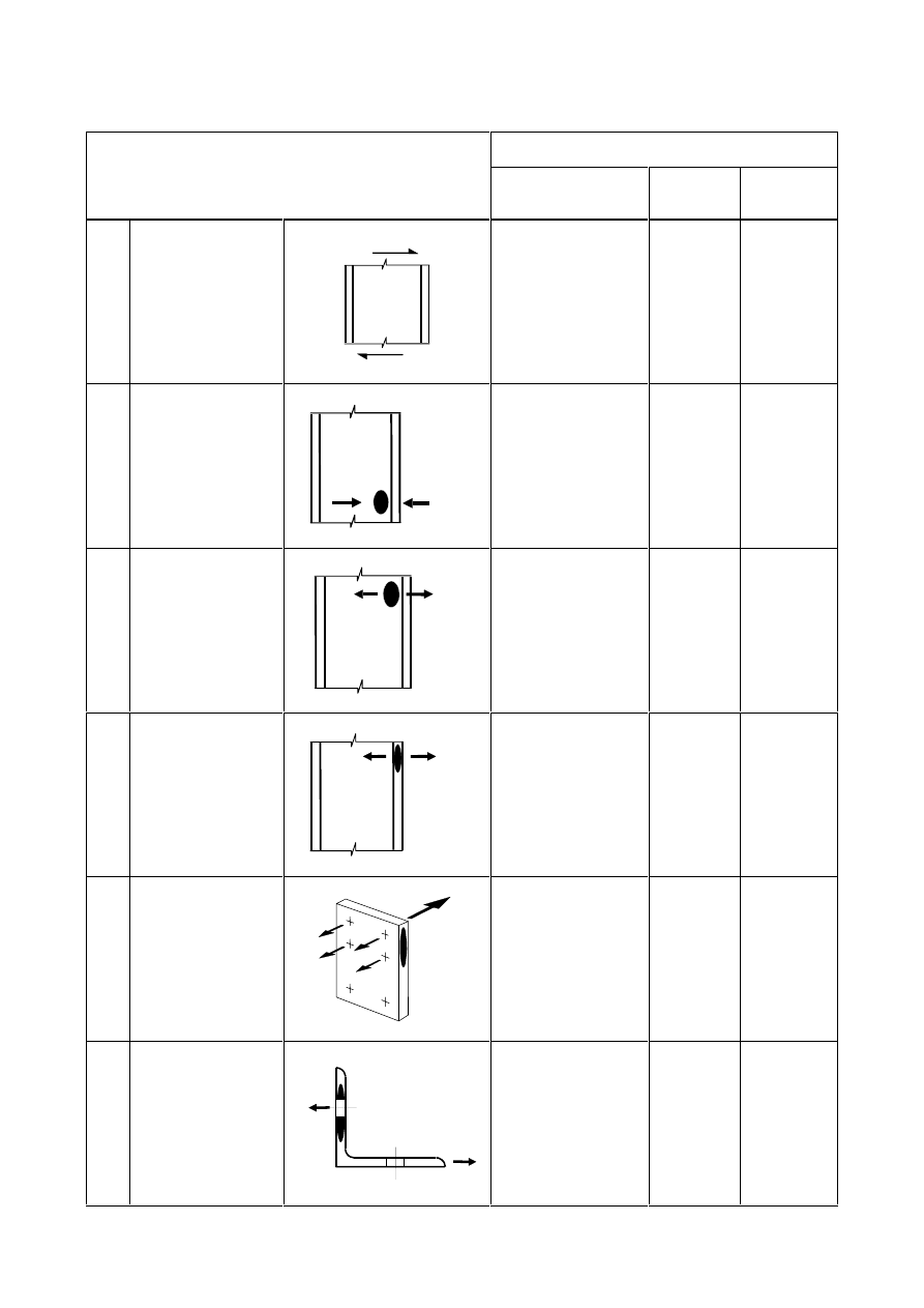
SU(1(
7DEOH%DVLFMRLQWFRPSRQHQWV
Reference to application rules
Component
Design
Resistance
Stiffness
coefficient
Rotation
capacity
1
Column web panel
in shear
9
(G
9
(G
6.2.6.1 6.3.2
6.4(4)
2
Column web
In transverse
compression
)
F(G
6.2.6.2 6.3.2
6.4(5)
and
6.4(6)
3
Column web
in transverse
tension
)
W(G
6.2.6.3 6.3.2
6.4(5)
4
Column flange
in bending
)
W(G
6.2.6.4 6.3.2
6.4(7)
5
End-plate
in bending
)
W(G
6.2.6.5 6.3.2
6.4(7)
6
Flange cleat
in bending
)
W(G
6.2.6.6 6.3.2
6.4(7)
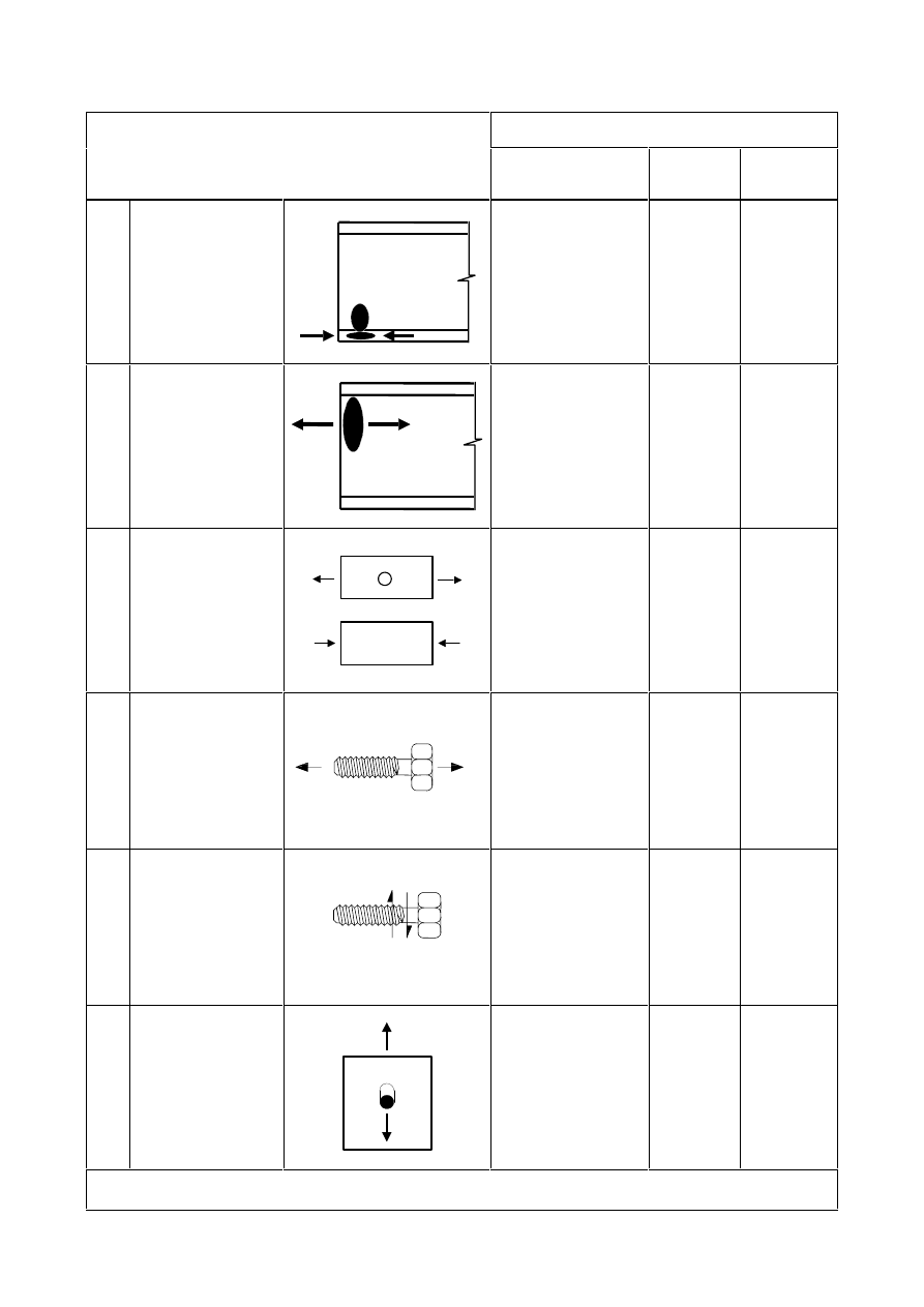
SU(1(
Reference to application rules
Component
Design
Resistance
Stiffness
coefficient
Rotation
capacity
7
Beam or column
flange and web
in compression
)
F(G
6.2.6.7 6.3.2
*)
8
Beam web
in tension
)
W(G
6.2.6.8 6.3.2
*)
9
Plate
in tension or
compression
)
F(G
)
F(G
)
W(G
)
W(G
in tension:
- EN 1993-1-1
in compression:
- EN 1993-1-1
6.3.2 *)
10
Bolts
in tension
)
W(G
With column flange:
- 6.2.6.4
with end-plate:
- 6.2.6.5
with flange cleat:
- 6.2.6.6
6.3.2 6.4(7)
11
Bolts
in shear
)
Y(G
3.6 6.3.2
6.4(2)
12
Bolts
in bearing
(on beam flange,
column flange,
end-plate or cleat)
)
E(G
)
E(G
3.6 6.3.2
*)
*)
No information available in this part.
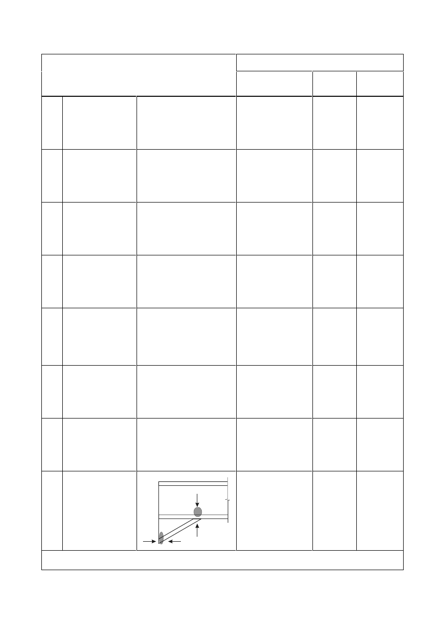
SU(1(
Reference to application rules
Component
Design
Resistance
Stiffness
coefficient
Rotation
capacity
13
Concrete
in compression
including grout
6.2.6.9
6.3.2
*)
14
Base plate
in bending under
compression
6.2.6.10
6.3.2
*)
15
Base plate in
bending under
tension
6.2.6.11
6.3.2
*)
16
Anchor bolts
in tension
6.2.6.12
6.3.2
*)
17
Anchor bolts
in shear
6.2.2
*)
*)
18
Anchor bolts
in bearing
6.2.2
*)
*)
19 Welds
4
6.3.2
*)
20 Haunched
beam
6.2.6.7 6.3.2
*)
*)
No information available in this part.

SU(1(
'HVLJQ5HVLVWDQFH
,QWHUQDOIRUFHV
(1)
The stresses due to the internal forces and moments in a member may be assumed not to affect the
design resistances of the basic components of a joint, except as specified in 6.2.1(2) and 6.2.1(3).
(2) The longitudinal stress in a column should be taken into account when determining the design
resistance of the column web in compression, see 6.2.6.2(2).
(3)
The shear in a column web panel should be taken into account when determining the design resistance
of the following basic components:
–
column web in transverse compression, see 6.2.6.2;
–
column web in transverse tension, see 6.2.6.3.
6KHDUIRUFHV
(1)
In welded connections, and in bolted connections with end-plates, the welds connecting the beam web
should be designed to transfer the shear force from the connected beam to the joint, without any
assistance from the welds connecting the beam flanges.
(2)
In bolted connections with end-plates, the design resistance of each bolt-row to combined shear and
tension should be verified using the criterion given in Table 3.4, taking into account the total tensile
force in the bolt, including any force due to prying action.
127(As a simplification, bolts required to resist in tension may be assumed to provide their full
design resistance in tension when it can be shown that the design shear force does not exceed the sum
of:
a)
the total design shear resistance of those bolts that are not required to resist tension and;
b)
(0,4/1,4) times the total design shear resistance of those bolts that are also required to resist
tension.
(3)
In bolted connections with angle flange cleats, the cleat connecting the compression flange of the
beam may be assumed to transfer the shear force in the beam to the column, provided that:
–
the gap
J between the end of the beam and the face of the column does not exceed the thickness
W
a
of the angle cleat;
–
the force does not exceed the design shear resistance of the bolts connecting the cleat to the
column;
–
the web of the beam satisfies the requirement given in EN 1993-1-5, section 6.
(4)
The design shear resistance of a joint may be derived from the distribution of internal forces within
that joint, and the design resistances of its basic components to these forces, see Table 6.1.
(5)
In base plates if no special elements for resisting shear are provided, such as block or bar shear
connectors, it should be demonstrated that either the design friction resistance of the base plate, see
6.2.2(6), or, in cases where the bolt holes are not oversized, the design shear resistance of the anchor
bolts, see 6.2.2(7), is sufficient to transfer the design shear force. The design bearing resistance of the
block or bar shear connectors with respect to the concrete should be checked according to EN 1992.
(6)
In a column base the design friction resistance
)
f,Rd
between base plate and grout should be derived
as follows:
)
f,Rd
=
&
f,d
1
c,Ed
...
(6.1)
where:

SU(1(
&
f,d
is the coefficient of friction between base plate and grout layer. The following values may be
used:
–
for
sand-cement
mortar
&
f,d
= 0,20
–
for other types of grout the coefficient of friction
&
f,d
should be determined by testing in
accordance with EN 1990, Annex D;
1
c,Ed
is the design value of the normal compressive force in the column.
127(If the column is loaded by a tensile normal force, )
f,Rd
= 0.
(7)
In a column base the design shear resistance of an anchor bolt
)
vb,Rd
should be taken as the smaller of
)
1,vb,Rd
and
)
2,vb,Rd
where
–
)
1,vb,Rd
is the design bearing resistance of the anchor bolt, see 3.6.1
–
)
2,vb,Rd
=
0E
V
XE
E
$
I
γ
α
...
(6.2)
where:
b
= 0,44 - 0,0003
I
yb
I
yb
is
the yield strength of the anchor bolt, where 235 N/mm
2
I
yb
1PP
2
(8)
The design shear resistance
)
v,Rd
of a column base plate should be derived as follows:
)
v,Rd
=
)
f,Rd
+
Q)
vb,Rd
...
(6.3)
where:
Q is the number of anchor bolts in the base plate.
(9)
The concrete and reinforcement used in the base should be designed in accordance with EN 1992.
%HQGLQJPRPHQWV
(1)
The design moment resistance of any joint may be derived from the distribution of internal forces
within that joint and the design resistances of its basic components to these forces, see Table 6.1.
(2)
Provided that the axial force
1
Ed
in the connected member does not exceed 5% of the design
resistance
1
p
5G
of its cross-section, the design moment resistance
0
j,Rd
of a beam-to column joint
or beam splice may be determined using the method given in 6.2.7.
(3)
The design moment resistance
0
j,Rd
of a column base may be determined using the method given in
6.2.8.
(4)
In all joints, the sizes of the welds should be such that the design moment resistance of the joint
0
j,Rd
is always limited by the design resistance of its other basic components, and not by the design
resistance of the welds.
(5)
In a beam-to-column joint or beam splice in which a plastic hinge is required to form and rotate under
any relevant load case, the welds should be designed to resist the effects of a moment equal to the
smaller of:
–
the design plastic moment resistance of the connected member
0
p
5G
–
WLPHVWKHGHVLJQPRPHQWUHVLVWDQFHRIWKHMRLQW0
j,Rd
where
= 1,4 - for frames in which the bracing system satisfies the criterion (5.1) in EN1993-1-1 clause
5.2.1(3) with respect to sway;
= 1,7 - for all other cases.
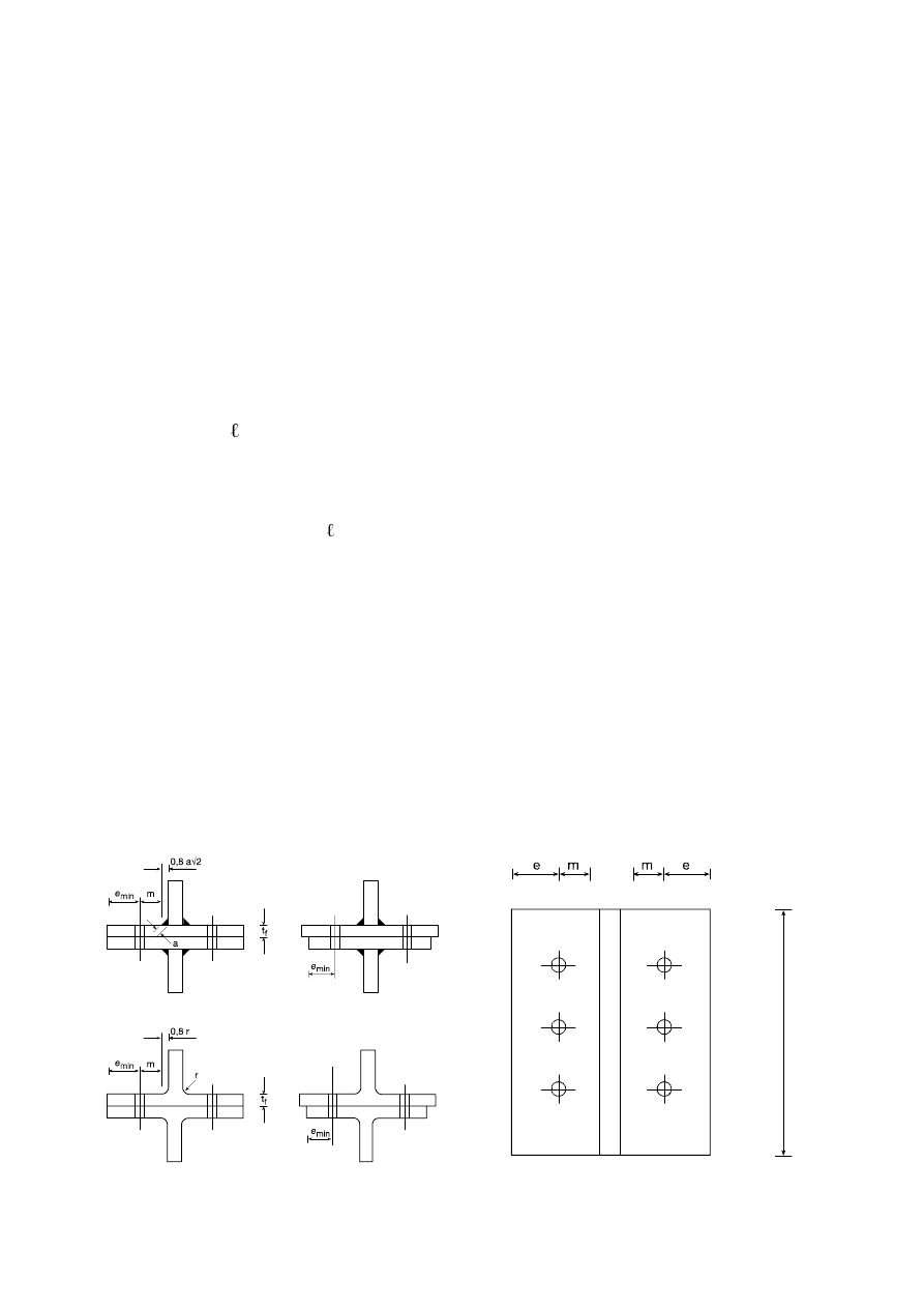
SU(1(
(6)
In a bolted connection with more than one bolt-row in tension, as a simplification the contribution of
any bolt-row may be neglected, provided that the contributions of all other bolt-rows closer to the
centre of compression are also neglected.
(TXLYDOHQW7VWXELQWHQVLRQ
*HQHUDO
(1)
In bolted connections an equivalent T-stub in tension may be used to model the design resistance of
the following basic components:
–
column flange in bending;
–
end-plate in bending;
–
flange cleat in bending;
–
base plate in bending under tension.
(2)
Methods for modelling these basic components as equivalent T-stub flanges, including the values to be
used for
H
min
,
eff
and
P
, are given in 6.2.6.
(3)
The possible modes of failure of the flange of an equivalent T-stub may be assumed to be similar to
those expected to occur in the basic component that it represents.
(4)
The total effective length
eff
of an equivalent T-stub, see Figure 6.2, should be such that the design
resistance of its flange is equivalent to that of the basic joint component that it represents.
127(The effective length of an equivalent T-stub is a notional length and does not necessarily
correspond to the physical length of the basic joint component that it represents.
(5)
The design tension resistance of a T-stub flange should be determined from Table 6.2.
127(Prying effects are implicitly taken into account when determining the design tension
resistance according to Table 6.2.
(6)
In cases where prying forces may develop, see Table 6.2, the design tension resistance of a T-stub
flange
)
T,Rd
should be taken as the smallest value for the three possible failure modes 1, 2 and 3.
(7)
In cases where prying forces may not develop, see Table 6.2, the design tension resistance of a T-stub
flange
)
T,Rd
should be taken as the smallest value for the two possible failure modes 1-2 and 3.
eff
(5
)LJXUH'LPHQVLRQVRIDQHTXLYDOHQW7VWXEIODQJH
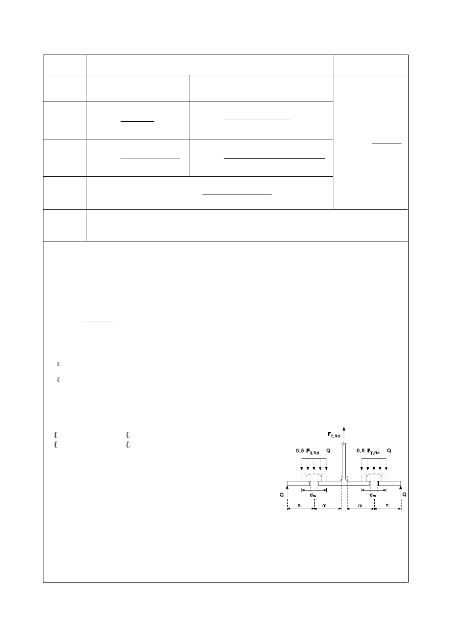
SU(1(
7DEOH'HVLJQ5HVLVWDQFHRID7VWXEIODQJH
Prying forces may develop, i.e.
/
b
/
b
*
No prying forces
0RGH
Method 1
Method 2 (alternative method)
without
backing
plates
)
T,1,Rd
=
P
0
5G
S ,
1
(,
4
)
T,1,Rd
=
)
(
2
)
2
8
(
,
1
(,
Q
P
H
PQ
0
H
Q
Z
5G
S
Z
+
−
−
with
backing
plates
)
T,1,Rd
=
P
0
0
5G
ES
5G
S
,
,
1
(,
2
4
+
)
T,1,Rd
=
)
(
2
4
)
2
8
(
,
,
1
(,
Q
P
H
PQ
Q0
0
H
Q
Z
5G
ES
5G
S
Z
+
−
+
−
0RGH
)
T,2,Rd
=
Q
P
)
Q
0
5G
W
5G
S
+
Σ
+
,
,
2
(,
2
)
T,1-2,Rd
=
P
0
5G
S ,
1
(
2
0RGH
)
T,3,Rd
=
5G
W
)
,
Σ
Mode 1: Complete yielding of the flange
Mode 2: Bolt failure with yielding of the flange
Mode 3: Bolt failure
/
b
is - the bolt elongation length, taken equal to the grip length (total thickness of material and
washers), plus half the sum of the height of the bolt head and the height of the nut or
- the anchor bolt elongation length, taken equal to the sum of 8 times the nominal bolt diameter,
the grout layer, the plate thickness, the washer and half the height of the nut
/
b
*
=
3
1
,
3
8
,
8
I
HII
V
W
$
P
"
Σ
)
T,Rd
is the design tension resistance of a T-stub flange
Q
is the prying force
0
p
5G
=
0
2
1
,
/
25
,
0
0
\
I
HII
I
W
γ
"
Σ
0
p
5G
=
0
2
2
,
/
25
,
0
0
\
I
HII
I
W
γ
"
Σ
0
bp,Rd
=
0
,
2
1
,
/
25
,
0
0
ES
\
ES
HII
I
W
γ
"
Σ
Q =
H
min
but
Q1,25P
)
t,Rd
is the design tension resistance of a bolt, see Table 3.4;
)
t,Rd
is the total value of
)
t,Rd
for all the bolts in the T-stub;
eff,1
is the value of
eff
for mode 1;
eff,2
is the value of
eff
for mode 2;
H
min
,
P and W
f
are as indicated in Figure 6.2.
I
y,bp
is the yield strength of the backing plates;
W
bp
is the thickness of the backing plates;
H
w
=
G
w
/
4;
G
w
is the diameter of the washer, or the width across points of
the bolt head or nut, as relevant.
127(In bolted beam-to-column joints or beam splices it may be assumed that prying forces
will develop.
127( In method 2, the force applied to the T-stub flange by a bolt is assumed to be uniformly
distributed under the washer, the bolt head or the nut, as appropriate, see figure, instead of
concentrated at the centre-line of the bolt. This assumption leads to a higher value for mode 1, but
leaves the values for
)
T,1-2,Rd
and modes 2 and 3 unchanged.
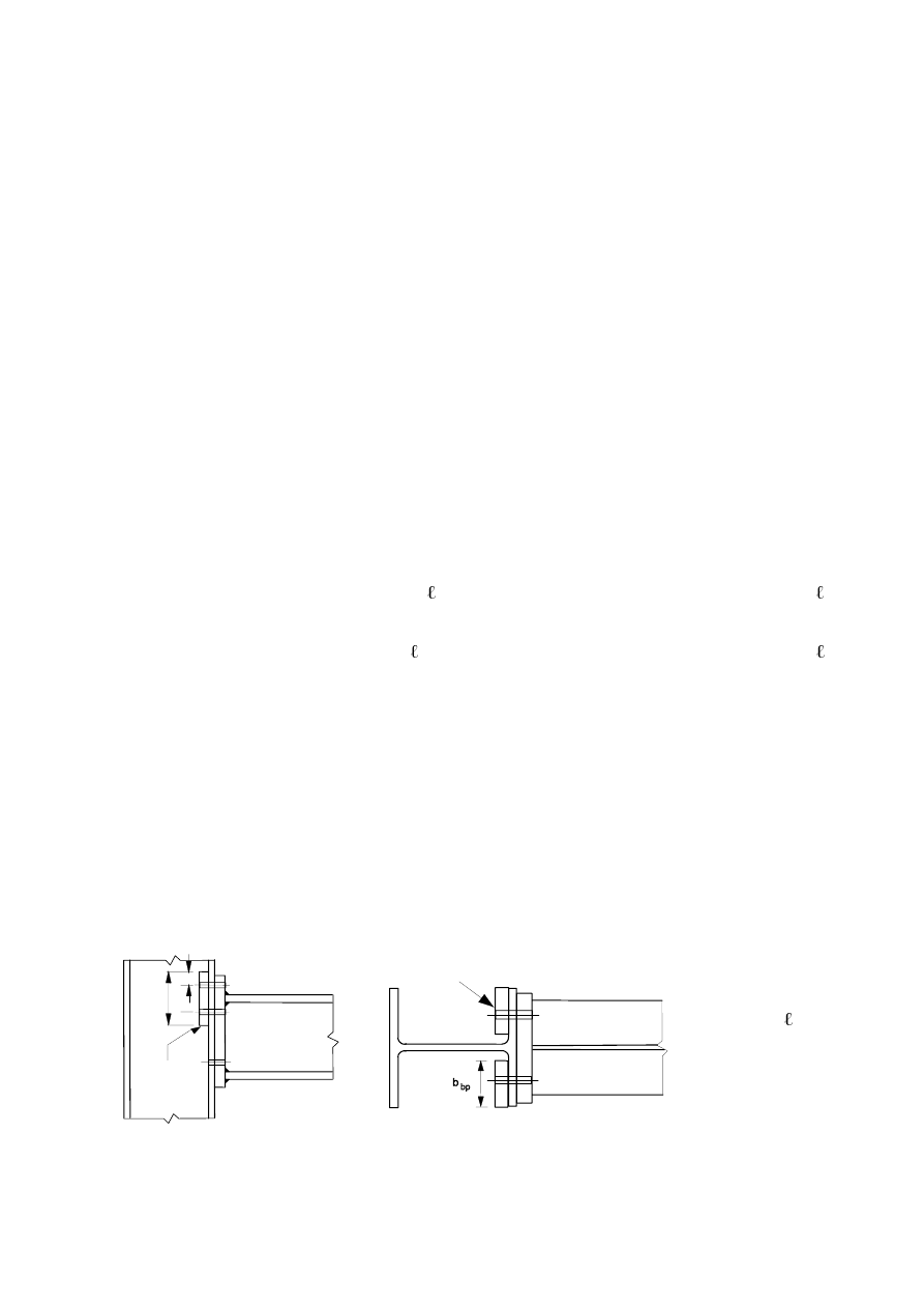
SU(1(
,QGLYLGXDOEROWURZVEROWJURXSVDQGJURXSVRIEROWURZV
(1) Although in an actual T-stub flange the forces at each bolt-row are generally equal, when an
equivalent T-stub flange is used to model a basic component listed in 6.2.4.1(1), allowance should be
made for the different in forces at each bolt-row.
(2)
When using the equivalent T-stub approach to model a group of bolt rows it may be necessary to
divide the group in to separate bolt-rows and use an equivalent T-stub to model each separate bolt-
row.
(3)
When using the T-stub approach to model a group of bolt rows the following conditions should be
satisfied:
a)
the force at each bolt-row should not exceed the design resistance determined considering only
that individual bolt-row;
b)
the total force on each group of bolt-rows, comprising two or more adjacent bolt-rows within
the same bolt-group, should not exceed the design resistance of that group of bolt-rows.
(4)
When determining the design tension resistance of a basic component represented by an equivalent
T-stub flange, the following parameters should be calculated:
a)
the maximum design resistance of an individual bolt-row, determined considering only that
bolt-row;
b)
the contribution of each bolt-row to the maximum design resistance of two or more adjacent
bolt-rows within a bolt-group, determined considering only those bolt-rows.
(5)
In the case of an individual bolt-row
eff
should be taken as equal to the effective length
eff
tabulated in 6.2.6 for that bolt-row taken as an individual bolt-row.
(6)
In the case of a group of bolt-rows
eff
should be taken as the sum of the effective lengths
eff
tabulated in 6.2.6 for each relevant bolt-row taken as part of a bolt-group.
%DFNLQJSODWHV
(1)
Backing plates may be used to reinforce a column flange in bending as indicated in Figure 6.3.
(2)
Each backing plate should extend at least to the edge of the column flange, and to within 3
mm of the
toe of the root radius or of the weld.
(3)
The backing plate should extend beyond the furthermost bolt rows active in tension as defined in
Figure 6.3.
(4)
Where backing plates are used, the design resistance of the T-stub
)
T,Rd
should be determined using
the method given in Table 6.2.
K
ES
H
ES
H
ES
1
1
K
bp
eff,1
H
bp
G
%DFNLQJSODWH
)LJXUH&ROXPQIODQJHZLWKEDFNLQJSODWHV
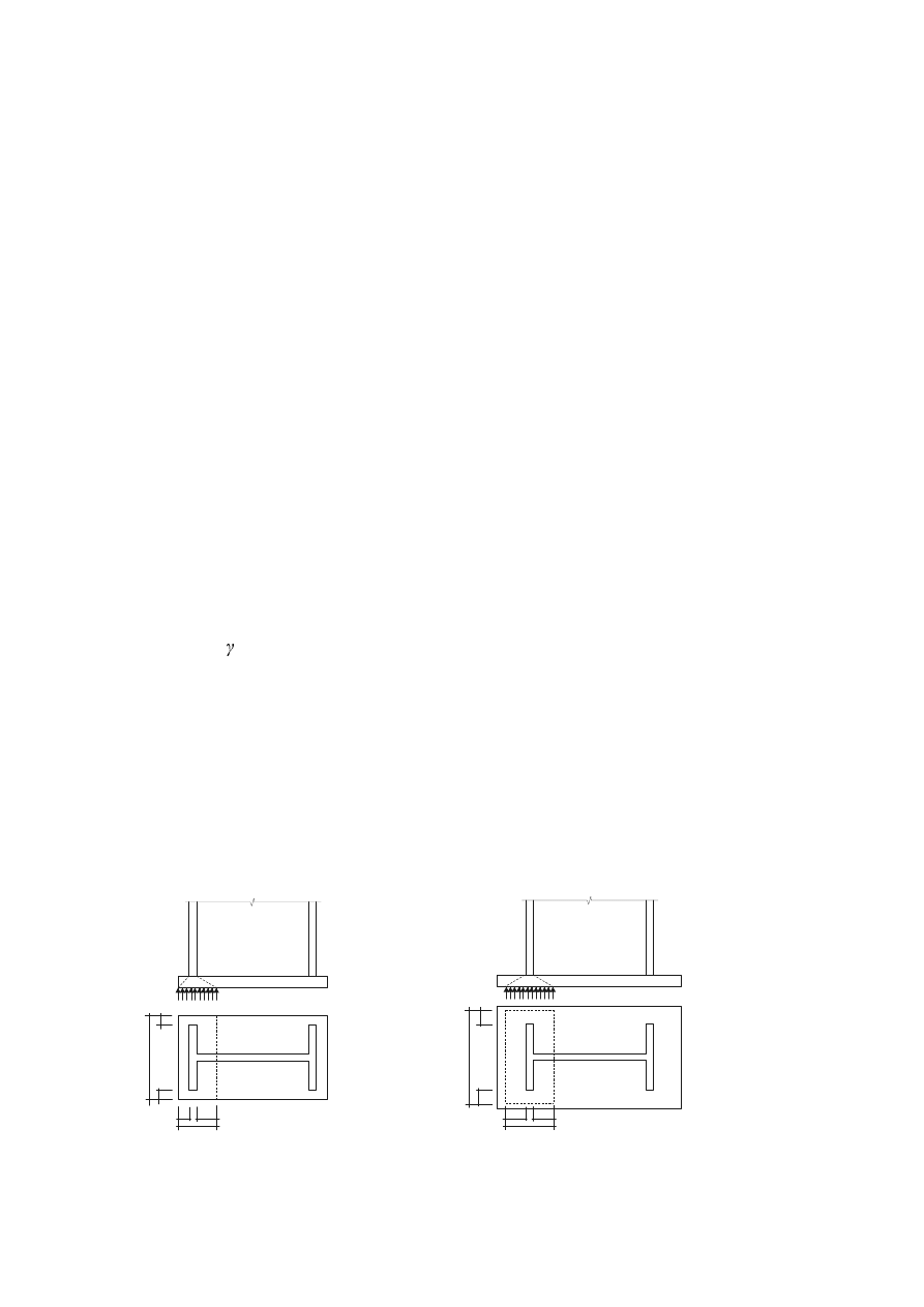
SU(1(
(TXLYDOHQW7VWXELQFRPSUHVVLRQ
(1)
In steel- to-concrete joints, the flange of an equivalent T-stub in compression may be used to model
the design resistances for the combination of the following basic components:
–
the steel base plate in bending under the bearing pressure on the foundation,
–
the concrete and/or grout joint material in bearing.
(2) The
total
length
O
eff
and the total width
E
eff
of an equivalent T-stub should be such that the design
compression resistance of the T-stub is equivalent to that of the basic joint component it represents.
127(The effective length and the effective width of an equivalent T-stub are notional lengths and
may be smaller than or equal to the physical dimensions of the basic joint component it represents.
(3)
The design compression resistance of a T-stub flange
)
C,Rd
should be determined as follows:
)
C,Rd
=
I
jd
E
eff
O
eff
...
(6.4)
where:
E
eff
is
the effective width of the T-stub flange, see 6.2.5(5) and 6.2.5(6)
O
eff
is
the effective length of the T-stub flange, see 6.2.5(5) and 6.2.5(6)
I
jd
is
the design bearing strength of the joint, see 6.2.5(7)
(4)
The forces transferred through a T-stub should be assumed to spread uniformly as shown in Figure
6.4(a) and (b). The pressure on the resulting bearing area should not exceed the design bearing
strength
I
j
and the additional bearing width, c, should not exceed:
F = W [I
y
/ (3
I
j
M0
)]
0.5
...
(6.5)
where:
W
is
the thickness of the T-stub flange;
I
y
is
the yield strength of the T-stub flange.
(5)
Where the projection of the physical length of the basic joint component represented by the T-stub is
less than
F, the effective area should be taken as indicated in Figure 6.4(a)
(6)
Where the projection of the physical length of the basic joint component represented by the T-stub
exceeds
F on any side, the part of the additional projection beyond the width F should be neglected, see
Figure 6.4(b).
O
eff
E
eff
F
≤
F
≤
F
≤
F
O
eff
E
eff
F
F
F
F
(a) Short projection
(b) Large projection
)LJXUH$UHDRIHTXLYDOHQW76WXELQFRPSUHVVLRQ
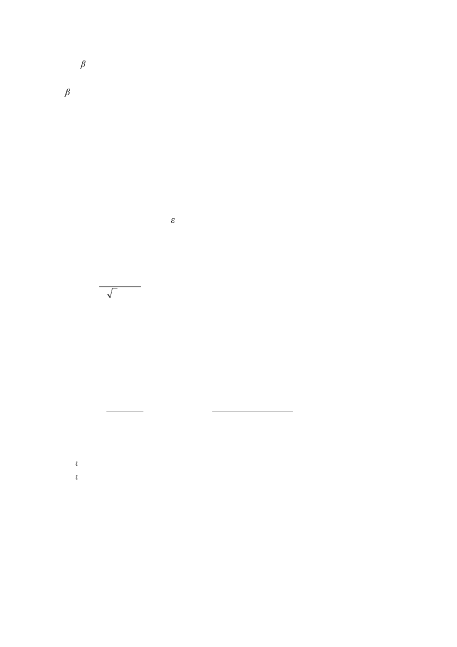
SU(1(
(7)
The design bearing strength of the joint
I
jd
should be determined from:
I
jd
=
j
)
Rdu
/ (
E
eff
O
eff
) ...
(6.6)
where:
j
is the foundation joint material coefficient, which may be taken as 2/3 provided that the
characteristic strength of the grout is not less than 0,2 times the characteristic strength of the
concrete foundation and the thickness of the grout is not greater than 0,2 times the smallest width
of the steel base plate. In cases where the thickness of the grout is more than 50 mm, the
characteristic strength of the grout should be at least the same as that of the concrete foundation.
)
Rdu
is
the concentrated design resistance force given in EN 1992, where
$
c0
is to be taken as (
E
eff
O
eff
).
'HVLJQ5HVLVWDQFHRIEDVLFFRPSRQHQWV
&ROXPQZHESDQHOLQVKHDU
(1)
The design methods given in 6.2.6.1(2) to 6.2.6.1(14) are valid provided the column web slenderness
satisfies the condition
G/W
w
.
(2)
For a single-sided joint, or for a double-sided joint in which the beam depths are similar, the design
shear resistance
9
wp,Rd
of an unstiffened column web panel, subject to a design shear force
9
wp,Ed
, see
5.3(3), should be obtained using:
9
wp,Rd
=
0
,
3
9
,
0
0
YF
ZF
\
$
I
γ
...
(6.7)
where:
$
vc
is
the shear area of the column, see EN 1993-1-1.
(3)
The design shear resistance may be increased by the use of stiffeners or supplementary web plates.
(4)
Where transverse web stiffeners are used in both the compression zone and the tension zone, the
design plastic shear resistance of the column web panel
9
wp,Rd
may be increased by
9
wp,add,Rd
given
by:
9
wp,add,Rd
=
V
5G
IF
S
G
0
,
(,
4
but
9
wp,add,Rd
V
5G
VW
S
5G
IF
S
G
0
0
,
(,
,
(,
2
2
+
... (6.8)
where:
G
s
is the distance between the centrelines of the stiffeners;
0
p
IF5G
is the design plastic moment resistance of a column flange
0
p
VW5G
is the design plastic moment resistance of a stiffener.
127(In welded joints, the transverse stiffeners should be aligned with the corresponding beam
flange.
(5)
When diagonal web stiffeners are used the design shear resistance of a column web should be
determined according to EN 1993-1-1.
127( In double-sided beam-to-column joint configurations without diagonal stiffeners on the
column webs, the two beams are assumed to have similar depths.
(6)
Where a column web is reinforced by adding a supplementary web plate, see Figure 6.5, the shear area
$
vc
may be increased by
E
s
W
wc
. If a further supplementary web plate is added on the other side of the
web, no further increase of the shear area should be made.
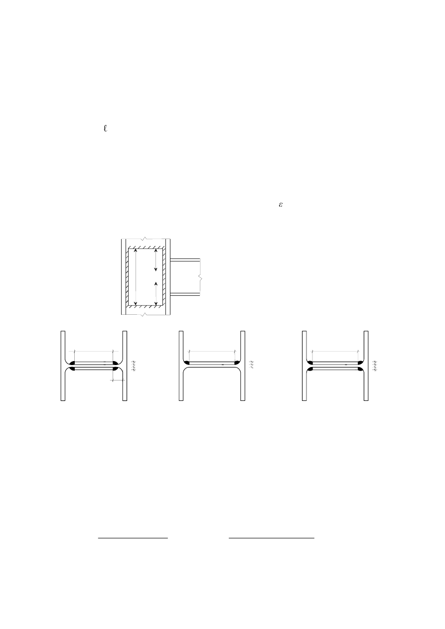
SU(1(
(7)
Supplementary web plates may also be used to increase the rotational stiffness of a joint by increasing
the stiffness of the column web in shear, compression or tension, see 6.3.2(1).
(8)
The steel grade of the supplementary web plate should be similar to that of the column.
(9)
The width
E
s
should be such that the supplementary web plate extends at least to the toe of the root
radius.
(10) The
length
s
should be such that the supplementary web plate extends throughout the effective width
of the web in tension and compression, see Figure 6.5.
(11) The
thickness
W
s
of the supplementary web plate should be not less than the column web thickness
W
wc
.
(12) The welds between the supplementary web plate and profile should be designed to resist the applied
design forces.
(13) The
width
E
s
of a supplementary web plate should be less than 40
W
s
.
(14) Discontinuous welds may be used in non corrosive environments.
b
eff,c
s
b
eff,t
O
a) Layout
t
t
t
w c
s
s
b
S
r+t
S
t t
t t
t
w c
w c
s s
s
b
S
b
S
127(
Weldability at the corner should be taken into account.
b) Examples of cross-section with longitudinal welds
)LJXUH([DPSOHVRIVXSSOHPHQWDU\ZHESODWHV
&ROXPQZHELQWUDQVYHUVHFRPSUHVVLRQ
(1)
The design resistance of an unstiffened column web subject to transverse compression should be
determined from:
)
c,wc,Rd
=
0
,
,
,
0
ZF
\
ZF
ZF
F
HII
ZF
I
W
E
N
γ
ω
but
)
c,wc,Rd
1
,
,
,
0
ZF
\
ZF
ZF
F
HII
ZF
I
W
E
N
γ
ρ
ω
...
(6.9)
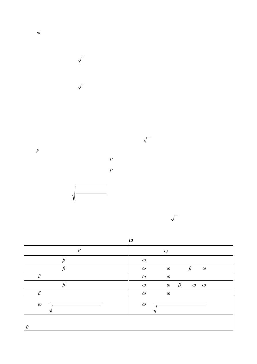
SU(1(
where:
is a reduction factor to allow for the possible effects of interaction with shear in the column
web panel according to Table 6.3;
E
eff,c,wc
is the effective width of column web in compression
–
for a welded connection:
E
eff,c,wc
=
)
(
5
2
2
V
W
D
W
IF
E
IE
+
+
+
...
(6.10)
D
c
,
U
c
and
D
b
are as indicated in Figure 6.6.
–
for bolted end-plate connection:
E
eff,c,wc
=
S
IF
S
IE
V
V
W
D
W
+
+
+
+
)
(
5
2
2
...
(6.11)
V
p
is the length obtained by dispersion at 45° through the end-plate (at least
W
p
and, provided that
the length of end-plate below the flange is sufficient, up to 2
W
p
).
–
for bolted connection with angle flange cleats:
E
eff,c,wc
=
)
(
5
6
,
0
2
V
W
U
W
IF
D
D
+
+
+
...
(6.12)
–
for a rolled I or H section column:
V U
c
–
for a welded I or H section column:
V =
F
D
2
is the reduction factor for plate buckling:
–
if
S
λ
+
= 1,0
... (6.13a)
–
if
S
λ
+
> 0,72:
= (
S
λ
+
í
/
S
λ
+
2
...
(6.13b)
S
λ
+
is the plate slenderness:
S
λ
+
=
2
,
,
,
932
,
0
ZF
ZF
\
ZF
ZF
F
HII
(W
I
G
E
...
(6.13c)
–
for a rolled I or H section column:
G
wc
=
K
c
í 2
(
W
fc
+
U
c
)
–
for a welded I or H section column:
G
wc
=
K
c
í
(
W
fc
+
D
2
)
N
wc
is a reduction factor and is given in 6.2.6.2(2).
7DEOH5HGXFWLRQIDFWRU IRULQWHUDFWLRQZLWKVKHDU
Transformation parameter
Reduction factor
0
0,5
= 1
0,5
< < 1
=
1
+ 2
(1
í )
(1
í
1
)
= 1
=
1
1
< < 2
=
1
+ (
í
(
2
í
1
)
= 2
=
2
1
=
2
,
,
)
/
(
3
,
1
1
1
YF
ZF
ZF
F
HII
$
W
E
+
2
=
2
,
,
)
/
(
2
,
5
1
1
YF
ZF
ZF
F
HII
$
W
E
+
$
vc
is
the shear area of the column, see 6.2.6.1;
is
the transformation parameter, see 5.3(7).
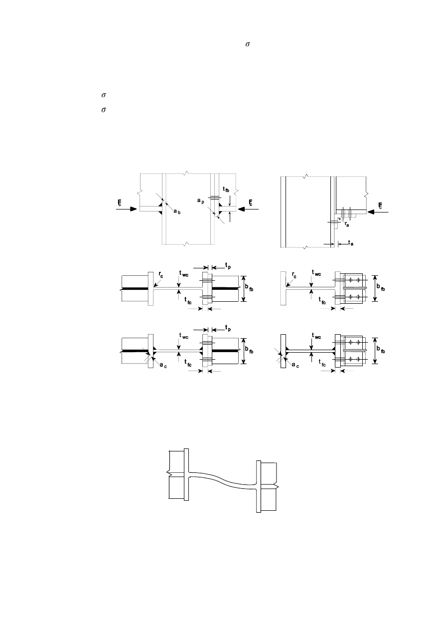
SU(1(
(2)
Where the maximum longitudinal compressive stress
com,Ed
due to axial force and bending moment
in the column exceeds 0,7
I
y,wc
in the web (adjacent to the root radius for a rolled section or the toe of
the weld for a welded section), its effect on the design resistance of the column web in compression
should be allowed for by multiplying the value of
)
c,wc,Rd
given by expression (6.9) by a reduction
factor
N
wc
as follows:
–
when
com,Ed
I
y,wc
:
N
wc
= 1
–
when
com,Ed
> 0,7
I
y,wc
:
N
wc
=
ZF
\
(G
FRP
I
,
,
/
7
,
1
σ
−
...
(6.14)
127(Generally the reduction factor N
wc
is 1,0 and no reduction is necessary. It can therefore be
omitted in preliminary calculations when the longitudinal stress is unknown and checked later.
Welded joint
Joint with end-plate
Joint with angle flange cleats
a) Elevation
b) Rolled column
c) Welded column
)LJXUH7UDQVYHUVHFRPSUHVVLRQRQDQXQVWLIIHQHGFROXPQ
(3) The
‘column-sway' buckling mode of an unstiffened column web in compression illustrated in Figure
6.7 should normally be prevented by constructional restraints.
)LJXUHµ&ROXPQVZD\¶EXFNOLQJPRGHRIDQXQVWLIIHQHGZHE
(4)
Stiffeners or supplementary web plates may be used to increase the design resistance of a column web
in transverse compression.
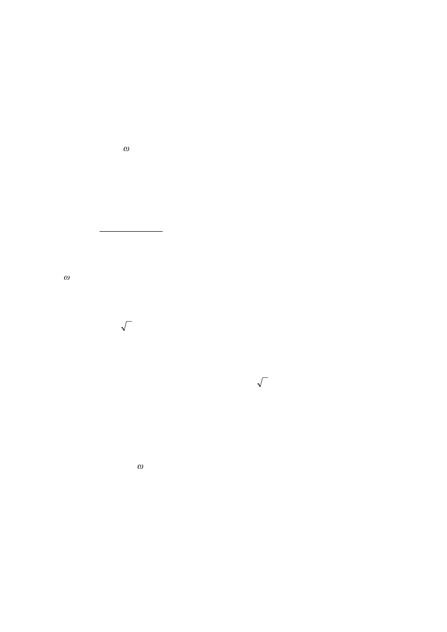
SU(1(
(5)
Transverse stiffeners or appropriate arrangements of diagonal stiffeners may be used in association
with or as an alternative to, transverse stiffeners in order to increase the design resistance of the
column web in compression.
127(In welded joints, the transverse stiffeners should be aligned with the corresponding beam
flange. In bolted joints, the stiffener in the compression zone should be aligned with the centre of
compression as defined Figure 6.15.
(6)
Where an unstiffened column web is reinforced by adding a supplementary web plate conforming with
6.2.6.1, the effective thickness of the web may be taken as 1,5
W
wc
if one supplementary web plate is
added, or 2,0
W
wc
if supplementary web plates are added to both sides of the web. In calculating the
reduction factor for the possible effects of shear stress, the shear area
$
vc
of the web may be
increased only to the extent permitted when determining its design shear resistance, see 6.2.6.1(6).
&ROXPQZHELQWUDQVYHUVHWHQVLRQ
(1)
The design resistance of an unstiffened column web subject to transverse tension should be determined
from:
)
t,wc,Rd
=
0
,
wc
,
,
t
0
ZF
\
ZF
W
HII
I
E
γ
ω
...
(6.15)
where:
is
a reduction factor to allow for the interaction with shear in the column web panel.
(2)
For a welded connection, the effective width
E
eff,t,wc
of a column web in tension should be obtained
using:
E
eff,t,wc
=
)
(
5
2
2
V
W
D
W
IF
E
IE
+
+
+
...
(6.16)
where:
–
for a rolled I or H section column:
V = U
c
–
for a welded I or H section column:
V =
F
D
2
where:
D
c
and
U
c
are as indicated in Figure 6.8 and
D
b
is as indicated in Figure 6.6.
(3)
For a bolted connection, the effective width
E
eff,t,wc
of column web in tension should be taken as equal
to the effective length of equivalent T-stub representing the column flange, see 6.2.6.4.
(4)
The reduction factor to allow for the possible effects of shear in the column web panel should be
determined from Table 6.3, using the value of
E
eff,t,wc
given in 6.2.6.3(2) or 6.2.6.3(3) as appropriate.
(5)
Stiffeners or supplementary web plates may be used to increase the design tension resistance of a
column web.
(6)
Transverse stiffeners and/or appropriate arrangements of diagonal stiffeners may be used to increase
the design resistance of the column web in tension.
127(In welded joints, the transverse stiffeners should be aligned with the corresponding beam
flange. In bolted joints, the stiffener in the compression zone should be aligned with the centre of
compression as defined in Figure 6.15.

SU(1(
(7)
The welds connecting diagonal stiffeners to the column flange should be fill-in welds with a sealing
run providing a combined throat thickness equal to the thickness of the stiffeners.
(8)
Where an unstiffened column web is reinforced by adding supplementary web plates conforming with
6.2.6.1, the design tension resistance depends on the throat thickness of the longitudinal welds
connecting the supplementary web plates. The effective thickness of the web
W
w,eff
should be taken as
follows:
–
when the longitudinal welds are full penetration butt welds with a throat thickness
D W
s
then:
–
for one supplementary web plate:
W
w,eff
= 1,5
W
wc
...
(6.17)
–
for supplementary web plates both sides:
W
w,eff
= 2,0
W
wc
...
(6.18)
–
when the longitudinal welds are fillet welds with a throat thickness
D
2
/
V
W
then for either
one or two supplementary web plates:
–
for steel grades S
235, S
275 or S
355:
W
w,eff
= 1,4
W
wc
... (6.19a)
–
for steel grades S
420 or S
460:
W
w,eff
= 1,3
W
wc
...
(6.19b)
(9)
In calculating the reduction factor for the possible effects of shear stress, the shear area
$
vc
of a
column web reinforced by adding supplementary web plates may be increased only to the extent
permitted when determining its design shear resistance, see 6.2.6.1(6).
&ROXPQIODQJHLQWUDQYHUVHEHQGLQJ
6.2.6.4.1 Unstiffened column flange, bolted connection
(1)
The design resistance and failure mode of an unstiffened column flange in tranverse bending, together
with the associated bolts in tension, should be taken as similar to those of an equivalent T-stub flange,
see 6.2.4, for both:
–
each individual bolt-row required to resist tension;
–
each group of bolt-rows required to resist tension.
(2)
The dimensions
H
min
and
P for use in 6.2.4 should be determined from Figure 6.8.
(3)
The effective length of equivalent T-stub flange should be determined for the individual bolt-rows and
the bolt-group in accordance with 6.2.4.2 from the values given for each bolt-row in Table 6.4.
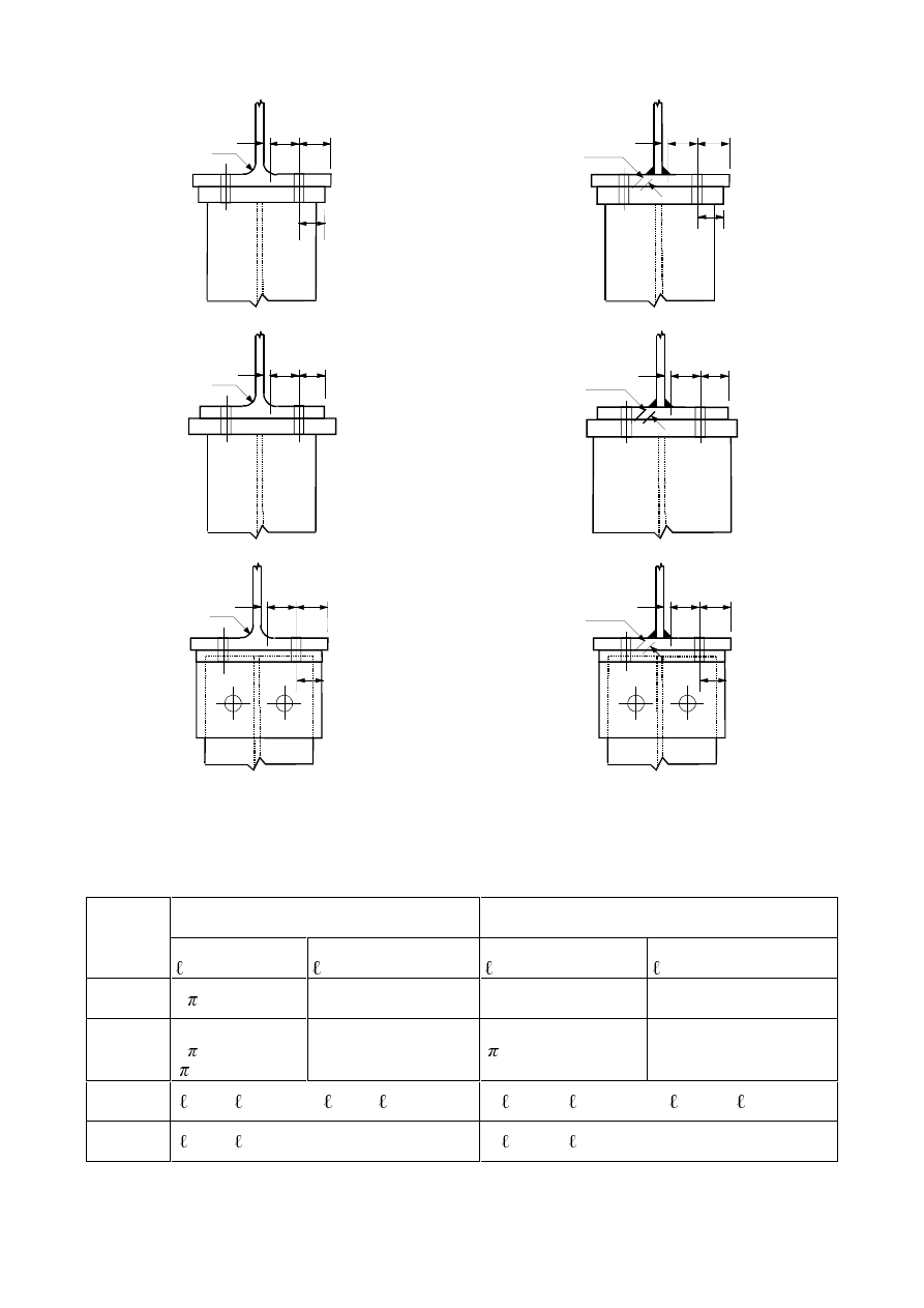
SU(1(
m
r
c
0,8 r
c
e
e
min
m
e
e
min
0,8 a
2
c
a
c
a) Welded end-plate narrower than column flange.
m
r
c
0,8 r
c
e
min
m
0,8 a
2
c
a
c
e
min
b) Welded end-plate wider than column flange.
m
r
c
0,8 r
c
e
e
min
m
e
e
min
0,8 a
2
c
a
c
c) Angle flange cleats.
)LJXUH'HILQLWLRQVRIHH
PLQ
U
F
DQGP
7DEOH(IIHFWLYHOHQJWKVIRUDQXQVWLIIHQHGFROXPQIODQJH
Bolt-row considered
individually
Bolt-row considered as
part of a group of bolt-rows
Bolt-row
Location
Circular patterns
eff,cp
Non-circular patterns
eff,nc
Circular patterns
eff,cp
Non-circular patterns
eff,nc
Inner
bolt-row
2
P
4
P + 1,25H
2
S
S
End
bolt-row
The smaller of:
2
P
P + 2H
1
The smaller of:
4
P + 1,25H
2
P + 0,625H + H
1
The smaller of:
P + S
2
H
1
+
S
The smaller of:
2
P + 0,625H + 0,5S
H
1
+ 0,5
S
Mode 1:
eff,1
=
eff,nc
but
eff,1
eff,cp
eff,1
=
eff,nc
but
eff,1
eff,cp
Mode 2:
eff,2
=
eff,nc
eff,2
=
eff,nc
SU(1(
6.2.6.4.2 Stiffened column flange, joint with bolted end-plate or flange cleats
(1)
Transverse stiffeners and/or appropriate arrangements of diagonal stiffeners may be used to increase
the design resistance of the column flange in bending.
(2)
The design resistance and failure mode of a stiffened column flange in transverse bending, together
with the associated bolts in tension, should be taken as similar to those of an equivalent T-stub flange,
see 6.2.4, for both:
–
each individual bolt-row required to resist tension;
–
each group of bolt-rows required to resist tension.
(3)
The groups of bolt-rows either side of a stiffener should be modelled as separate equivalent T-stub
flanges, see Figure 6.9. The design resistance and failure mode should be determined separately for
each equivalent T-stub.
(QGEROWURZDGMDFHQWWRDVWLIIHQHU
(QGEROWURZ
,QQHUEROWURZ
%ROWURZDGMDFHQWWRDVWLIIHQHU
)LJXUH0RGHOOLQJDVWLIIHQHGFROXPQIODQJHDVVHSDUDWH7VWXEV
(4)
The dimensions
H
min
and
P for use in 6.2.4 should be determined from Figure 6.8.
(5)
The effective lengths of an equivalent T-stub flange
eff
should be determined in accordance with
6.2.4.2 using the values for each bolt-row given in Table 6.5
7KHYDOXHRI IRUXVHLQTable 6.5
should be obtained from Figure 6.11.
(6)
The stiffeners should meet the requirements specified in 6.2.6.1.
SU(1(
7DEOH(IIHFWLYHOHQJWKVIRUDVWLIIHQHGFROXPQIODQJH
Bolt-row considered
individually
Bolt-row considered as
part of a group of bolt-rows
Bolt-row
Location
Circular patterns
eff,cp
Non-circular
patterns
eff,nc
Circular patterns
eff,cp
Non-circular patterns
eff,nc
Bolt-row adjacent
to a stiffener
2
P
P
P + S
0,5
S + P
íP + 0,625H)
Other inner
bolt-row
2
P
4
P + 1,25H
2
S
S
Other end
bolt-row
The smaller of:
2
P
P + 2H
1
The smaller of:
4
P + 1,25H
2
P + 0,625H + H
1
The smaller of:
P + S
2
H
1
+
S
The smaller of:
2
P + 0,625H + 0,5S
H
1
+ 0,5
S
End bolt-row
adjacent to a
stiffener
The smaller of:
2
P
P + 2H
1
H
1
+
P
íP + 0,625H)
not relevant
not relevant
For Mode 1:
eff,1
=
eff,nc
but
eff,1
eff,cp
eff,1
=
eff,nc
but
eff,1
eff,cp
For Mode 2:
eff,2
=
eff,nc
eff,2
=
eff,nc
VKRXOGEHREWDLQHGIURPFigure 6.11.
6.2.6.4.3 Unstiffened column flange, welded connection
(1)
In a welded joint, the design resistance
)
fc,Rd
of an unstiffened column flange in bending, due to
tension or compression from a beam flange, should be obtained using:
)
fc,Rd
=
0
,
,
,
/
0
IE
IE
IF
E
HII
I
W
E
γ
γ
...
(6.20)
where:
E
eff,b,fc
is the effective breath
E
eff
defined in 4.10 where the beam flange is considered as a plate.
127(The requirements specified in 4.10(4) and 4.10(6) should be satisfied.
(QGSODWHLQEHQGLQJ
(1)
The design resistance and failure mode of an end-plate in bending, together with the associated bolts
in tension, should be taken as similar to those of an equivalent T-stub flange, see 6.2.4 for both:
–
each individual bolt-row required to resist tension;
–
each group of bolt-rows required to resist tension.
(2)
The groups of bolt-rows either side of any stiffener connected to the end-plate should be treated as
separate equivalent T-stubs. In extended end-plates, the bolt-row in the extended part should also be
treated as a separate equivalent T-stub, see Figure 6.10. The design resistance and failure mode should
be determined separately for each equivalent T-stub.
(3) The
dimension
H
min
required for use in 6.2.4 should be obtained from Figure 6.8 for that part of the
end-plate located between the beam flanges. For the end-plate extension
H
min
should be taken as
equal to
H
x
, see Figure 6.10.
(4)
The effective length of an equivalent T-stub flange
eff
should be determined in accordance with
6.2.4.2 using the values for each bolt-row given in Table 6.6.
SU(1(
(5)
The values of
P and P
x
for use in Table 6.6 should be obtained from Figure 6.10.
b
p
w
e
x
m
x
5
eff
5
eff
5
eff
p
e
e
The extension of the end-plate and the portion
between the beam flanges are modelled as two
separate equivalent T-stub flanges.
For the end-plate extension, use
H
x
and
P
x
in
place of
H
and
P
when determining the design
resistance of the equivalent T-stub flange.
)LJXUH0RGHOOLQJDQH[WHQGHGHQGSODWHDVVHSDUDWH7VWXEV
7DEOH(IIHFWLYHOHQJWKVIRUDQHQGSODWH
Bolt-row considered
individually
Bolt-row considered as
part of a group of bolt-rows
Bolt-row
location
Circular patterns
eff,cp
Non-circular patterns
eff,nc
Circular patterns
eff,cp
Non-circular
patterns
eff,nc
Bolt-row outside
tension flange
of beam
Smallest of:
2
P
x
P
x
+
Z
P
x
+ 2
H
Smallest of:
4
P
x
+ 1,25
H
x
H+2P
x
+0,625
H
x
0,5
E
p
0,5
Z+2P
x
+0,625
H
x
—
—
First bolt-row
below tension
flange of beam
2
P
P
P + p
0,5
S + P
íP + 0,625H)
Other inner
bolt-row
2
P
4
P + 1,25 H
2
S
S
Other end
bolt-row
2
P
4
P + 1,25 H
P + S
2
P+0,625H+0,5S
Mode 1:
eff,1
=
eff,nc
but
eff,1
eff,cp
eff,1
=
eff,nc
but
eff,1
eff,cp
Mode 2:
eff,2
=
eff,nc
eff,2
=
eff,nc
VKRXOGEHREWDLQHGIURPFigure 6.11.
SU(1(
)LJXUH9DOXHVRI IRUVWLIIHQHGFROXPQIODQJHVDQGHQGSODWHV
)ODQJHFOHDWLQEHQGLQJ
(1)
The design resistance and failure mode of a bolted angle flange cleat in bending, together with the
associated bolts in tension, should be taken as similar to those of an equivalent T-stub flange, see
6.2.4.
(2)
The effective length
eff
of the equivalent T-stub flange should be taken as 0,5
E
a
where
E
a
is the
length of the angle cleat, see Figure 6.12.
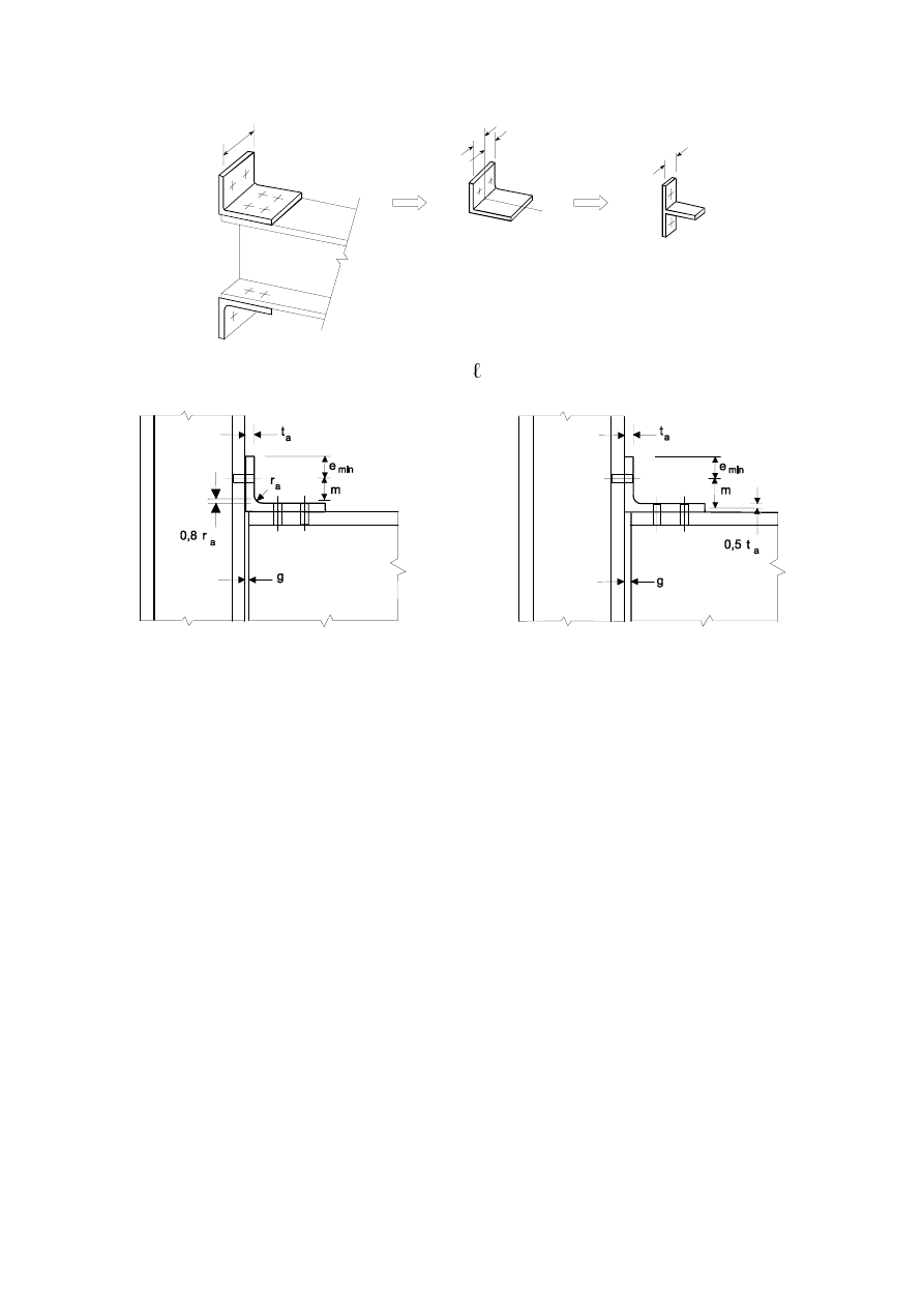
SU(1(
(3)
The dimensions
H
min
and
P for use in 6.2.4 should be determined from Figure 6.13.
5
eff
5
eff
b
a
5
eff
)LJXUH(IIHFWLYHOHQJWK
HII
RIDQDQJOHIODQJHFOHDW
a)
Gap
J
W
a
b) Gap
J
> 0,4
W
a
Notes:
-
The number of bolt-rows connecting the cleat to the column flange is limited to one;
-
The number of bolt-rows connecting the cleat to the beam flange is not limited;
-
The length
E
a
of the cleat may be different from both the width of the beam flange and the width
of the column flange.
)LJXUH'LPHQVLRQVH
PLQ
DQGPIRUDEROWHGDQJOHFOHDW
%HDPIODQJHDQGZHELQFRPSUHVVLRQ
(1)
The design compression resistance of a beam flange and the adjacent compression zone of the beam
web, may be assumed to act at the level of the centre of compression, see 6.2.7. The design
compression resistance of the combined beam flange and web is given by the following expression:
)
c,fb,Rd
=
0
c,Rd
/
(
K íW
fb
) ...
(6.21)
where:
K
is the depth of the connected beam;
0
c,Rd
is the design moment resistance of the beam cross-section, reduced if necessary to allow for
shear, see EN 1993-1-1. For a haunched beam
0
c,Rd
may be calculated neglecting the
intermediate flange.
W
fb
is the flange thickness of the connected beam.

SU(1(
If the height of the beam including the haunch exceeds 600 mm the contribution of the beam web to
the design compression resistance should be limited to 20%.
(2)
If a beam is reinforced with haunches they should be arranged such that:
–
the steel grade of the haunch should match that of the member;
–
the flange size and the web thickness of the haunch should not be less than that of the member;
–
the angle of the haunch flange to the flange of the member should not be greater than 45°;
–
the length of stiff bearing
V
s
should be taken as equal to the thickness of the haunch flange parallel
to the beam.
(3)
If a beam is reinforced with haunches, the design resistance of beam web in compression should be
determined according to 6.2.6.2.
%HDPZHELQWHQVLRQ
(1)
In a bolted end-plate connection, the design tension resistance of the beam web should be obtained
from:
)
t,wb,Rd
=
0
,
,
,
/
0
ZE
\
ZE
ZE
W
HII
I
W
E
γ
...
(6.22)
(2)
The effective width
E
eff,t,wb
of the beam web in tension should be taken as equal to the effective length
of the equivalent T-stub representing the end-plate in bending, obtained from 6.2.6.5 for an individual
bolt-row or a bolt-group.
&RQFUHWHLQFRPSUHVVLRQLQFOXGLQJJURXW
(1)
The design bearing strength of the joint between the base plate and its concrete support should be
determined taking account of the material properties and dimensions of both the grout and the concrete
support. The concrete support should be designed according to EN 1992.
(2)
The design resistance of concrete in compression, including grout, together with the associated base
plate in bending
)
c,pl,Rd
, should be taken as similar to those of an equivalent T-stub, see 6.2.5.
%DVHSODWHLQEHQGLQJXQGHUFRPSUHVVLRQ
(1)
The design resistance of a base plate in bending under compression, together with concrete slab on
which the column base is placed
)
c,pl,Rd
, should be taken as similar to those of an equivalent T-stub,
see 6.2.5.
%DVHSODWHLQEHQGLQJXQGHUWHQVLRQ
(1)
The design resistance and failure mode of a base plate in bending under tension, together with the
associated anchor bolts in tension
)
t,pl,Rd
, may be determined using the rules given in 6.2.6.5.
(2)
In the case of base plates prying forces which may develop should not be taken into consideration.
$QFKRUEROWLQWHQVLRQ
(1)
Anchor bolts should be designed to resist the effects of the design loads. They should provide design
resistance to tension due to uplift forces and bending moments where appropriate.
(2)
When calculating the tension forces in the anchor bolts due to bending moments, the lever arm should
not be taken as more than the distance between the centroid of the bearing area on the compression
side and the centroid of the bolt group on the tension side.
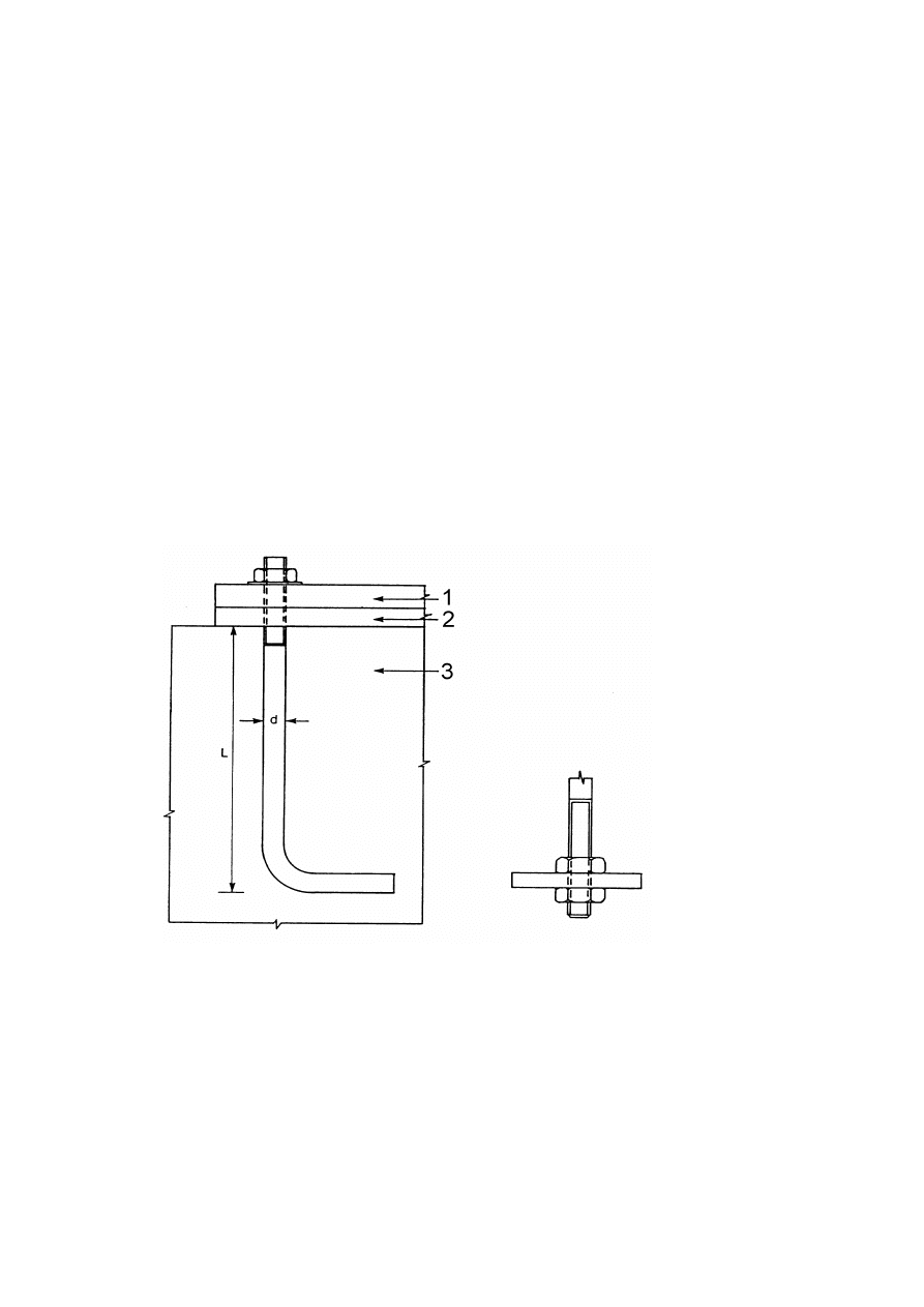
SU(1(
127(Tolerances on the positions of the anchor bolts should be taken into account if the influence
of tolerances is significant.
(3)
The design resistance of the anchor bolts should be taken as the smaller of the design tension
resistance of the anchor bolt, see 3.6, and the design bond resistance of the concrete on the anchor bolt
according to EN 1992-1-1.
(4)
One of the following methods should be used to secure anchor bolts into the foundation:
–
a hook (Figure 6.14(a)),
–
a washer plate (Figure 6.14(b)),
–
some other appropriate load distributing member embedded in the concrete,
–
some other fixing which has been adequately tested and approved.
(5)
When the bolts are provided with a hook, the anchorage length should be such as to prevent bond
failure before yielding of the bolt. The anchorage length should be calculated in accordance with
EN 1992-1-1. This type of anchorage should not be used for bolts with a yield strength
I
yb
higher than
300 N/mm
2
.
(6)
When the anchor bolts are provided with a washer plate or other load distributing member, no account
should be taken of the contribution of bond. The whole of the force should be transferred through the
load distributing device.
%DVHSODWH
*URXW
&RQFUHWHIRXQGDWLRQ
(a) Hook
(b) Washer plate
)LJXUH)L[LQJRIDQFKRUEROWV
'HVLJQ0RPHQWUHVLVWDQFHRIEHDPWRFROXPQMRLQWVDQGVSOLFHV
*HQHUDO
(1)
The applied design moment
0
j,Ed
shall satisfy:

SU(1(
5G
M
(G
M
0
0
,
,
... (6.23)
(2)
The methods given in 6.2.7 for determining the design moment resistance of a joint
0
j,Rd
do not take
account of any co-existing axial force
1
Ed
in the connected member. They should not be used if the
axial force in the connected member exceeds 5% of the design plastic resistance
1
p
5G
of its cross-
section.
(3)
If the axial force
1
Ed
in the connected beam exceeds 5% of the design resistance,
1
pl,Rd
, the following
conservative method may be used:
5G
M
(G
M
5G
M
(G
M
1
1
0
0
,
,
,
,
+
...
(6.24)
where:
0
j.Rd
is the design moment resistance of the joint, assuming no axial force;
1
j.Rd
is the axial design resistance of the joint, assuming no applied moment.
(4)
The design moment resistance of a welded joint should be determined as indicated in Figure 6.15(a).
(5)
The design moment resistance of a bolted joint with a flush end-plate that has only one bolt-row in
tension (or in which only one bolt-row in tension is considered, see 6.2.3(6)) should be determined as
indicated in Figure 6.15(b).
(6)
The design moment resistance of a bolted joint with angle flange cleats should be determined as
indicated in Figure 6.15(c).
(7)
The design moment resistance of a bolted end-plate joint with more than one row of bolts in tension
should generally be determined as specified in 6.2.7.2.
(8)
As a conservative simplification, the design moment resistance of an extended end-plate joint with
only two rows of bolts in tension may be approximated as indicated in Figure 6.16, provided that the
total design resistance
)
Rd
does not exceed 3,8
)
t,Rd
, where
)
t,Rd
is given in Table 6.2. In this case
the whole tension region of the end-plate may be treated as a single basic component. Provided that
the two bolt-rows are approximately equidistant either side of the beam flange, this part of the end-
plate may be treated as a T-stub to determine the bolt-row force
)
1,Rd
. The value of
)
2,Rd
may then
be assumed to be equal to
)
1,Rd
, and so
)
Rd
may be taken as equal to 2
)
1,Rd
.
(9)
The centre of compression should be taken as the centre of the stress block of the compression forces.
As a simplification the centre of compression may be taken as given in Figure 6.15.
(10) A splice in a member or part subject to tension shall be designed to transmit all the moments and
forces to which the member or part is subjected at that point.
(11) Splices shall be designed to hold the connected members in place. Friction forces between contact
surfaces may not be relied upon to hold connected members in place in a bearing splice.
(12) Wherever practicable the members should be arranged so that the centroidal axis of any splice material
coincides with the centroidal axis of the member. If eccentricity is present then the resulting forces
should be taken into account.
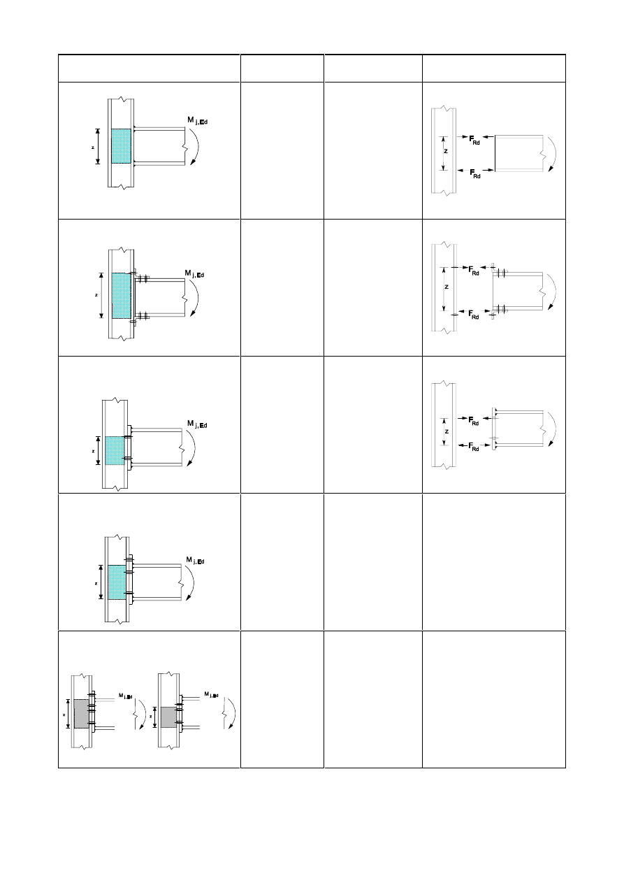
SU(1(
Type of connection
Centre of
compression
Lever arm
Force distributions
a) Welded
connection
In line with the
mid thickness
of the
compression
flange
] = K - W
fb
K is the depth of
the connected
beam
W
fb
is the thickness
of the beam
flange
b)
Bolted connection with angle
flange cleats
In line with the
mid-thickness
of the leg of the
angle cleat on
the
compression
flange
Distance from the
centre of
compression to the
bolt-row in tension
c)
Bolted end-plate connection
with only one bolt-row active in
tension
In line with the
mid-thickness
of the
compression
flange
Distance from the
centre of
compression to the
bolt-row in tension
d)
Bolted extended end-plate
connection with only two bolt-rows
active in tension
In line with the
mid-thickness
of the
compression
flange
Conservatively z
may be taken as
the distance from
the centre of
compression to a
point midway
between these two
bolt-rows
e)
Other bolted end-plate
connections with two or more bolt-
rows in tension
In line with the
mid-thickness
of the
compression
flange
An approximate
value may be
obtained by taking
the distance from
the centre of
compression to a
point midway
between the
farthest two bolt-
rows in tension
A more accurate value may
be determined by taking the
lever arm
] as equal to ]
eq
obtained using the method
given in 6.3.3.1.
)LJXUH&HQWUHRIFRPSUHVVLRQOHYHUDUP]DQGIRUFHGLVWULEXWLRQVIRU
GHULYLQJWKHGHVLJQPRPHQWUHVLVWDQFH0
M5G
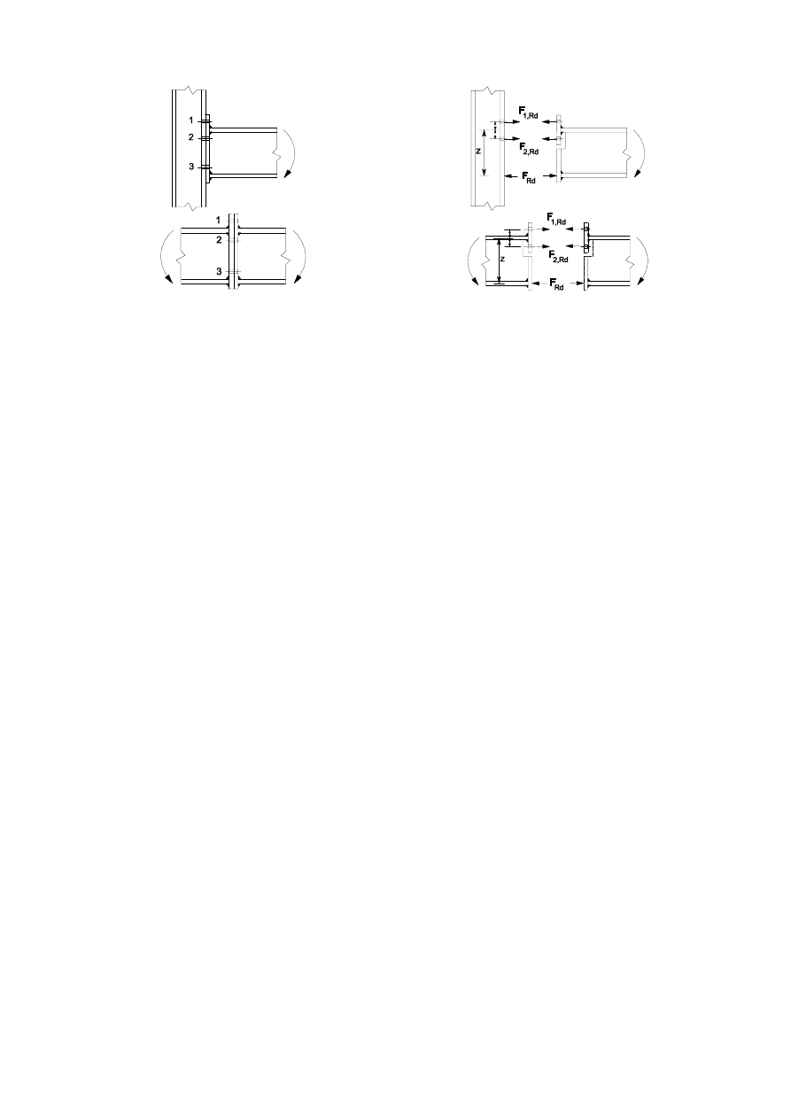
SU(1(
)LJXUH6LPSOLILHGPRGHOVIRUEROWHGMRLQWVZLWKH[WHQGHGHQGSODWHV
(13) Where the members are not prepared for full contact in bearing, splice material should be provided to
transmit the internal forces and moments in the member at the spliced section, including the moments
due to applied eccentricity, initial imperfections and second-order deformations. The internal forces
and moments should be taken as not less than a moment equal to 25% of the moment capacity of the
weaker section about both axes and a shear force equal to 2.5% of the normal force capacity of the
weaker section in the directions of both axes.
(14) Where the members are prepared for full contact in bearing, splice material should be provided to
transmit 25% of the maximum compressive force in the column.
(15) The alignment of the abutting ends of members subjected to compression should be maintained by
cover plates or other means. The splice material and its fastenings should be proportioned to carry
forces at the abutting ends, acting in any direction perpendicular to the axis of the member. In the
design of splices the second order effects should also be taken into account.
(16) Splices in flexural members should comply with the following:
a)
Compression flanges should be treated as compression members;
b) Tension flanges should be treated as tension members;
c)
Parts subjected to shear should be designed to transmit the following effects acting together:
–
the shear force at the splice;
–
the moment resulting from the eccentricity, if any, of the centroids of the groups of fasteners
on each side of the splice;
–
the proportion of moment, deformation or rotations carried by the web or part, irrespective of
any shedding of stresses into adjoining parts assumed in the design of the member or part.
%HDPWRFROXPQMRLQWVZLWKEROWHGHQGSODWHFRQQHFWLRQV
(1)
The design moment resistance
0
j,Rd
of a beam-to-column joint with a bolted end-plate connection
may be determined from:
0
j,Rd
=
5G
WU
U
U
)
K
,
Σ
...
(6.25)
where:
)
t
U,Rd
is the effective design tension resistance of bolt-row
U ;
K
U
is the distance from bolt-row
U to the centre of compression;
U
is the bolt-row number.

SU(1(
127(In a bolted connection with more than one bolt-row in tension, the bolt-rows are numbered
starting from the bolt-row farthest from the centre of compression.
(2)
For bolted end-plate connections, the centre of compression should be assumed to be in line with the
centre of the compression flange of the connected member.
(3)
The effective design tension resistance
)
tr,Rd
for each bolt-row should be determined in sequence,
starting from bolt-row 1, the bolt-row farthest from the centre of compression, then progressing to
bolt-row 2, etc.
(4)
When determining the value of
)
t
U,Rd
for bolt-row
U the effective design tension resistance of all
other bolt-rows closer to the centre of compression should be ignored.
(5)
The effective design tension resistance
)
t
U,Rd
of bolt-row
U should be taken as its design tension
resistance
)
t,Rd
as an individual bolt-row determined from 6.2.7.2(6), reduced if necessary to satisfy
the conditions specified in 6.2.7.2(7), (8) and (9).
(6)
The effective design tension resistance
)
tr,Rd
of bolt-row
U ,taken as an individual bolt-row, should
be taken as the smallest value of the design tension resistance for an individual bolt-row of the
following basic components:
–
the column web in tension
)
t,wc,Rd
- see
6.2.6.3;
–
the column flange in bending
)
t,fc,Rd
- see
6.2.6.4;
–
the end-plate in bending
)
t,ep,Rd
- see
6.2.6.5;
–
the beam web in tension
)
t,wb,Rd
- see
6.2.6.8.
(7)
The effective design tension resistance
)
t
U,Rd
of bolt-row
U should, if necessary, be reduced below
the value of
)
t,Rd
given by 6.2.7.2(6) to ensure that, when account is taken of all bolt-rows up to and
including bolt-row
U
the following conditions are satisfied:
–
the total design resistance
)
t,Rd
9
wp,Rd
/ - with from 5.3(7)
-
see 6.2.6.1;
–
the total design resistance
)
t,Rd
does not exceed the smaller of:
–
the design resistance of the column web in compression
)
c,wc,Rd
- see
6.2.6.2;
–
the design resistance of the beam flange and web in compression
)
c,
fb,Rd
-
see 6.2.6.7.
(8)
The effective design tension resistance
)
t
U,Rd
of bolt-row
U should, if necessary, be reduced below
the value of
)
t,Rd
given by 6.2.7.2(6), to ensure that the sum of the design resistances taken for the
bolt-rows up to and including bolt-row
U that form part of the same group of bolt-rows, does not
exceed the design resistance of that group as a whole. This should be checked for the following basic
components:
–
the column web in tension
)
t,wc,Rd
- see
6.2.6.3;
–
the column flange in bending
)
t,fc,Rd
- see
6.2.6.4;
–
the end-plate in bending
)
t,ep,Rd
- see
6.2.6.5;
–
the beam web in tension
)
t,wb,Rd
- see
6.2.6.8.
(9)
Where the effective design tension resistance
)
tx,Rd
of one of the previous bolt-rows
[ is greater than
1,9
)
t,Rd
, then the effective design tension resistance
)
t
U,Rd
for bolt-row
U should be reduced, if
necessary, in order to ensure that:
)
tr,Rd
)
tx,Rd
K
r
/
K
x
...
(6.26)
where:
K
x
is
the distance from bolt-row
[ to the centre of compression;
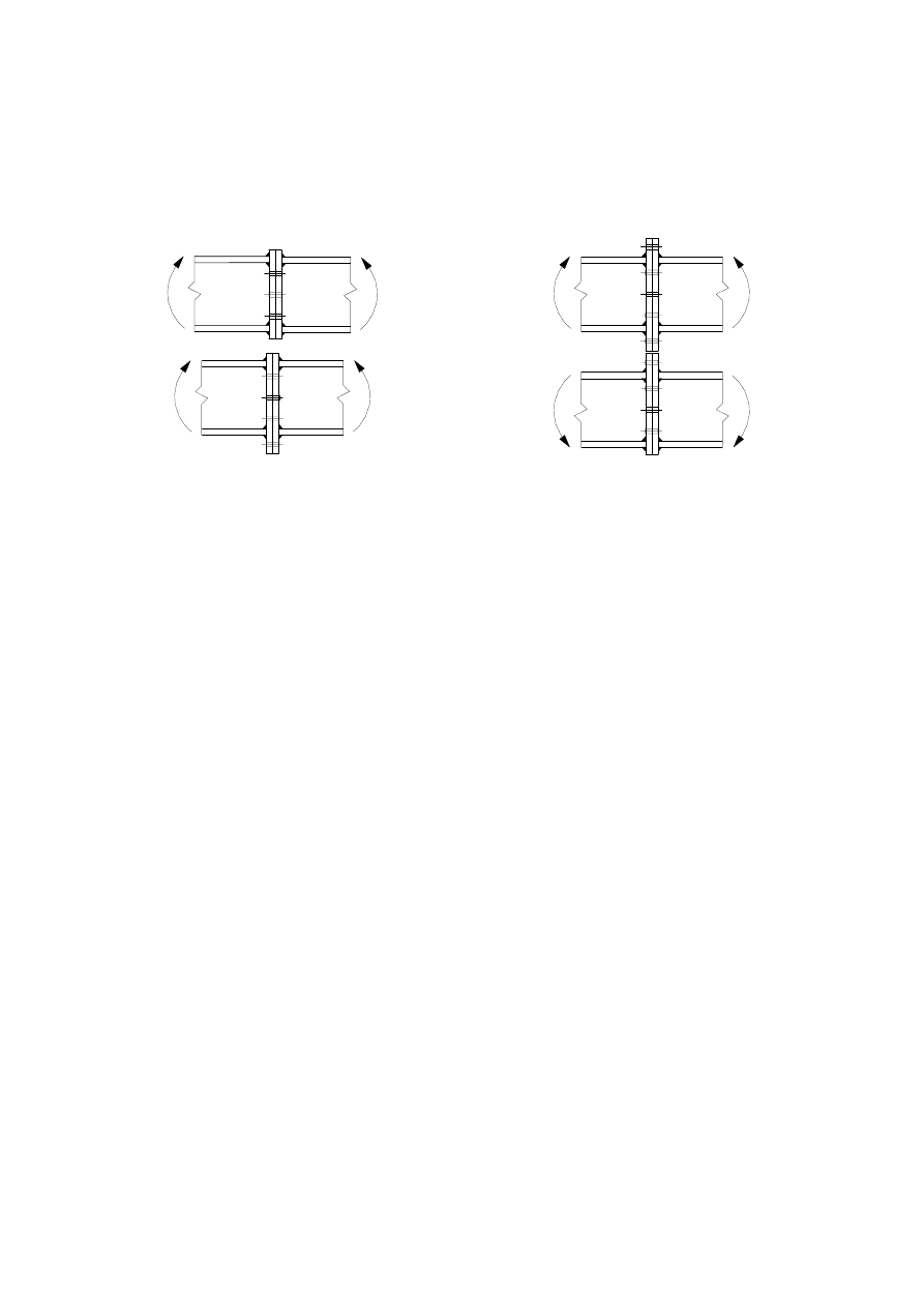
SU(1(
[ is the bolt-row farthest from the centre of compression that has a design tension resistance
greater than 1,9
)
t,Rd
.
127( The National Annex may give other situations where equation (6.26) is relevant.
(10) The method described in 6.2.7.2(1) to 6.2.7.2(9) may be applied to a bolted beam splice with welded
end-plates, see Figure 6.17, by omitting the items relating to the column.
)LJXUH%ROWHGEHDPVSOLFHVZLWKZHOGHGHQGSODWHV
'HVLJQ5HVLVWDQFHRIFROXPQEDVHVZLWKEDVHSODWHV
*HQHUDO
(1)
Column bases should be of sufficient size, stiffness and strength to transmit the axial forces, bending
moments and shear forces in columns to their foundations or other supports without exceeding the
load carrying capacity of these supports.
(2)
The design bearing strength between the base plate and its support may be determined on the basis of a
uniform distribution of compressive force over the bearing area. For concrete foundations the bearing
strength should not exceed the design bearing strength,
I
jd ,
given in 6.2.5(7).
(3)
For a column base subject to combined axial force and bending the forces between the base plate and
its support can take one of the following distribution depending on the relative magnitude of the
applied axial force and bending moment:
–
In the case of a dominant compressive axial force, full compression may develop under both
column flanges as shown in Figure 6.18(a).
–
In the case of a dominant tensile force, full tension may develop under both flanges as shown in
Figure 6.18(b).
–
In the case of a dominant bending moment compression may develop under one column flange
and tension under the other as shown in Figure 6.18(c) and Figure 6.18(d).
(4)
Base plates should be designed using the appropriate methods given in 6.2.8.2 and 6.2.8.3.
(5)
One of the following methods should be used to resist the shear force between the base plate and its
support:
–
Frictional design resistance at the joint between the base plate and its support.
–
The design shear resistance of the anchor bolts.
–
The design shear resistance of the surrounding part of the foundation.
If anchor bolts are used to resist the shear forces between the base plate and its support, rupture of the
concrete in bearing should also be checked, according to EN 1992.
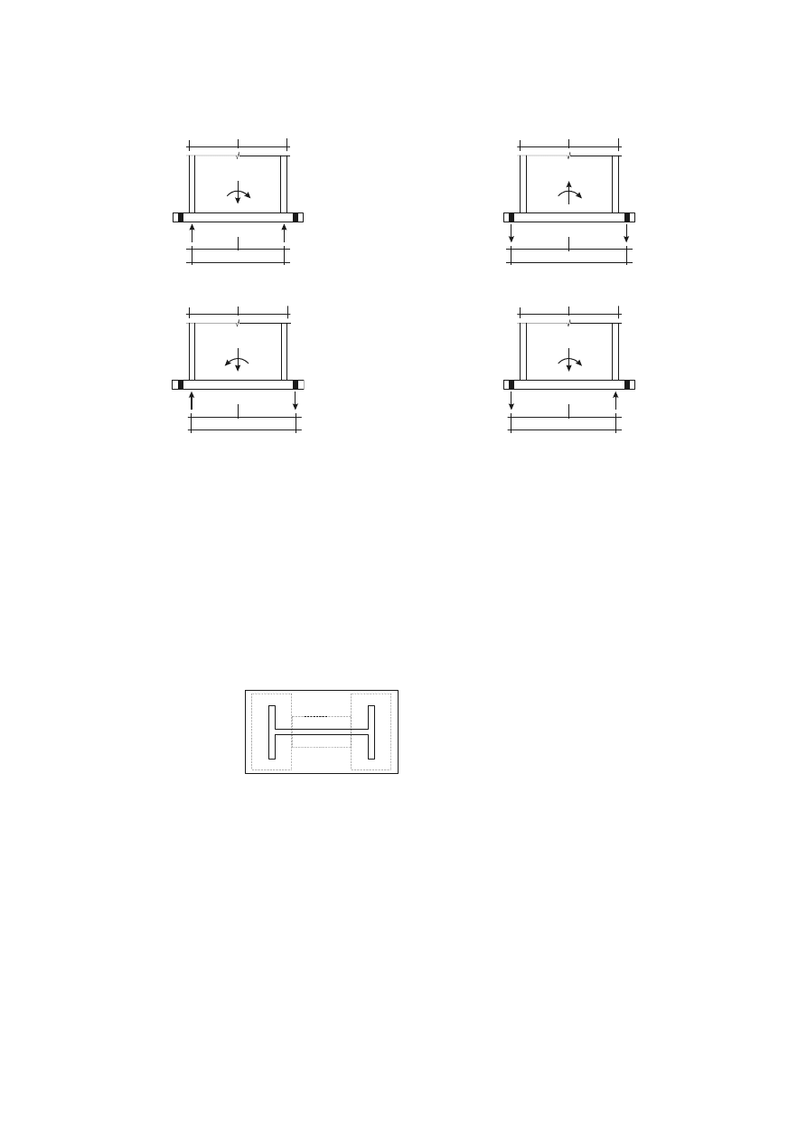
SU(1(
Where the above methods are inadequate special elements such as blocks or bar shear connectors
should be used to transfer the shear forces between the base plate and its support.
M
Ed
]
C,l
]
]
C,r
N
Ed
M
Ed
]
T,l
]
]
T,r
N
Ed
a) Column base connection in case of a
dominant compressive normal force
b) Column base connection in case of a
dominant tensile normal force
M
Ed
]
C,l
]
]
T,r
N
Ed
M
Ed
]
T,l
]
]
C,r
N
Ed
c) Column base connection in case of a
dominant bending moment
d) Column base connection in case of a
dominant bending moment
)LJXUH'HWHUPLQDWLRQRIWKHOHYHUDUP]IRUFROXPQEDVHFRQQHFWLRQV
&ROXPQEDVHVRQO\VXEMHFWHGWRD[LDOIRUFHV
(1)
The design resistance,
1
j,Rd ,
of a symmetric column base plate subject to an axial compressive force
applied concentrically may be determined by adding together the individual design resistance
)
C,Rd
of
the three T-stubs shown in Figure 6.19 (Two T-stubs under the column flanges and one T-stub under
the column web.) The three T-stubs should not be overlapping, see Figure 6.19. The design resistance
of each of these T-stubs should be calculated using the method given in 6.2.5.
1
3
2
7VWXE
7VWXE
7VWXE
)LJXUH1RQRYHUODSSLQJ7VWXEV
&ROXPQEDVHVVXEMHFWHGWRD[LDOIRUFHVDQGEHQGLQJPRPHQWV
(1)
The design moment resistance
0
j,Rd
of a column base subject to combined axial force and moment
should be determined using the method given in Table 6.7 where the contribution of the concrete
portion just under the column web (T-stub 2 of Figure 6.19) to the compressive capacity is omitted.
The following parameters are used in this method:
–
)
T,l,Rd
is the design tension resistance of the left hand side of the joint -
see 6.2.8.3(2)
–
)
T,r,Rd
is the design tension resistance of the right hand side of the joint -
see 6.2.8.3(3)
–
)
C,l,Rd
is the design compressive resistance of the left hand side of the joint
-
see 6.2.8.3(4)
–
)
C,r,Rd
is the design compressive resistance of the right hand side of the joint -
see 6.2.8.3(5)

SU(1(
(2)
The design tension resistance
)
T,l,Rd
of the left side of the joint should be taken as the smallest values
of the design resistance of following basic components:
–
the column web in tension under the left column flange
)
t,wc,Rd
-
see
6.2.6.3;
–
the base plate in bending under the left column flange
)
t,pl,Rd
-
see 6.2.6.11.
(3)
The design tension resistance
)
T,r,Rd
of the right side of the joint should be taken as the smallest values
of the design resistance of following basic components:
–
the column web in tension under the right column flange
)
t,wc,Rd
- see
6.2.6.3;
–
the base plate in bending under the right column flange
)
t,pl,Rd
-
see 6.2.6.11.
(4)
The design compressive resistance
)
C,l,Rd
of the left side of the joint should be taken as the smallest
values of the design resistance of following basic components:
–
the concrete in compression under the left column flange
)
c,pl,Rd
-
see 6.2.6.9;
–
the left column flange and web in compression
)
c,fc,Rd
-
see 6.2.6.7.
(5)
The design compressive resistance
)
C,r,Rd
of the right side of the joint should be taken as the smallest
values of the design resistance of following basic components:
–
the concrete in compression under the right column flange
)
c,pl,Rd
-
see 6.2.6.9;
–
the right column flange and web in compression
)
c,fc,Rd
-
see 6.2.6.7.
(6)
For the calculation of
]
T,l
,
]
C,l
,
]
T,r
,
]
C,r
see 6.2.8.1.
7DEOH'HVLJQPRPHQWUHVLVWDQFH0
M5G
RIFROXPQEDVHV
Loading
Lever arm
]
Design moment resistance
0
j,Rd
]= ]
T,l
+ ]
C,r
1
Ed
> 0 and
H > ]
T,l
1
Ed
and
H -]
C,r
Left side in tension
Right side in compression
The smaller of
1
/
,
,
1
,
+
H
]
]
)
U
&
5G
7
and
1
/
1
,
,
,
−
−
H
]
]
)
7
5G
U
&
]= ]
T,l
+ ]
T,r
1
Ed
> 0 and
0 <
H < ]
T,l
1
Ed
> 0 and
-
]
T,r
<
H
Left side in tension
Right side in tension
The smaller of
1
/
,
,
1
,
+
H
]
]
)
U
7
5G
7
and
1
/
1
,
,
,
−
H
]
]
)
7
5G
U
7
The smaller of
1
/
,
,
1
,
+
H
]
]
)
U
7
5G
7
and
1
/
1
,
,
1
,
−
H
]
]
)
7
5G
7
]= ]
C,l
+ ]
T,r
1
Ed
> 0 and
H -]
T,r
1
Ed
and
H > ]
C,l
Left side in compression
Right side in tension
The smaller of
1
/
,
,
1
,
+
−
H
]
]
)
U
7
5G
&
and
1
/
1
,
,
,
−
H
]
]
)
&
5G
U
7
]= ]
C,l
+ ]
C,r
1
Ed
and
0 <
H < ]
C,l
1
Ed
and
-
]
C,r
<
H
Left side in compression
Right side in compression
The smaller of
1
/
,
,
1
,
+
−
H
]
]
)
U
&
5G
&
and
1
/
1
,
,
,
−
−
H
]
]
)
&
5G
U
&
The smaller of
1
/
,
,
1
,
+
−
H
]
]
)
U
&
5G
&
and
1
/
1
,
,
,
−
−
H
]
]
)
&
5G
U
&
0
Ed
> 0 is clockwise,
1
Ed
> 0 is tension
H =
(G
(G
1
0
=
5G
5G
1
0

SU(1(
5RWDWLRQDOVWLIIQHVV
%DVLFPRGHO
(1)
The rotational stiffness of a joint should be determined from the flexibilities of its basic components,
each represented by an elastic stiffness coefficient
N
L
obtained from 6.3.2.
127(These elastic stiffness coefficients are for general application.
(2)
For bolted end-plate connections with more than one row of bolts in tension, the stiffness coefficients
N
L
for the related basic components should be combined. For beam-to-column joints and beam splices
a method is given in 6.3.3 and for column bases a method is given in 6.3.4.
(3)
In a bolted connection with more than one bolt-row in tension, as a simplification the contribution of
any bolt-row may be neglected, provided that the contributions of all other bolt-rows closer to the
centre of compression are also neglected. The number of bolt-rows retained need not necessarily be
the same as for the determination of the design moment resistance.
(4)
Provided that the axial force
1
Ed
in the connected member does not exceed 5% of the design
resistance
1
p
5G
of its cross-section, the rotational stiffness
6
j
of a beam-to-column joint or beam
splice, for a moment
0
j,Ed
less than the design moment resistance
0
j,Rd
of the joint, may be obtained
with sufficient accuracy from:
6
j
=
∑
L
L
N
(]
1
2
µ
...
(6.27)
where:
N
L
is
the stiffness coefficient for basic joint component
L
;
] is the lever arm, see 6.2.7;
is the stiffness ratio 6
j,ini
/
6
j
, see 6.3.1(6);
127(The initial rotational stiffness 6
j,ini
of the joint is given by expression (6.27) with
= 1,0.
(5)
The rotational stiffness
6
j
of a column base, for a moment
0
j,Ed
less than the design moment
resistance
0
j,Rd
of the joint, may be obtained with sufficient accuracy from 6.3.4.
(6)
The stiffness ratio
should be determined from the following:
–
if
0
j,Ed
0
j,Rd
:
= 1
... (6.28a)
–
if 2/3
0
j,Rd
<
0
j,Ed
0
j,Rd
:
=
Ψ
)
/
5
,
1
(
,
,
5G
M
(G
M
0
0
...
(6.28b)
in which the coefficient is obtained from Table 6.8.
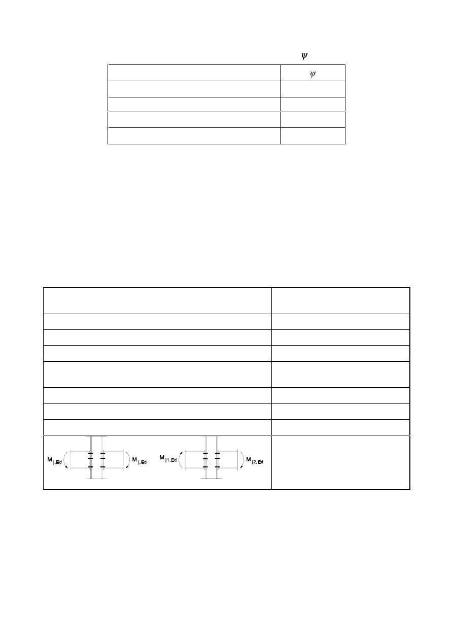
SU(1(
7DEOH9DOXHRIWKHFRHIILFLHQW
Type of connection
Welded
2,7
Bolted end-plate
2,7
Bolted angle flange cleats
3,1
Base plate connections
2,7
(7)
The basic components that should be taken into account when calculating the stiffness of a welded
beam-to-column connection and a bolted angle flange cleat are given in Table 6.9. Similarly, the basic
components for a bolted end-plate connection and a base plate are given in Table 6.10. In both of these
tables the stiffness coefficients,
N
L
,for the basic components are defined in Table 6.11.
(8)
For beam-to-column end plate joints the following procedure should be used for obtaining the joint
stiffness. The equivalent stiffness coefficient,
N
HT
, and the equivalent lever arm,
]
HT
, of the connection
should be obtained from 6.3.3. The stiffness of the joint should then be obtained from 6.3.1(4) based
on the stiffness coefficients,
N
HT
(for the connection),
N
(for the column web in shear),
and with the
lever arm,
], taken equal to the equivalent lever arm of the connection, ]
HT
.
7DEOH-RLQWVZLWKZHOGHGFRQQHFWLRQVRUEROWHGDQJOHIODQJHFOHDW
FRQQHFWLRQV
Beam-to-column joint with
welded connections
Stiffness coefficients
N
L
to be taken
into account
Single-sided
N
1
;
N
2
;
N
3
Double-sided – Moments equal and opposite
N
2
;
N
3
Double-sided – Moments unequal
N
1
;
N
2
;
N
3
Beam-to-column joint with
Bolted angle flange cleat connections
Stiffness coefficients
N
L
to be taken
into account
Single-sided
N
1
;
N
2
;
N
3
;
N
4
;
N
6
;
N
10
;
N
11
*
)
;
N
12
**
)
Double-sided – Moments equal and opposite
N
2
;
N
3
;
N
4
;
N
6
;
N
10
;
N
11
*
)
;
N
12
**
)
Double-sided – Moments unequal
N
1
;
N
2
;
N
3
;
N
4
;
N
6
;
N
10
;
N
11
*
)
;
N
12
**
)
Moments equal and opposite
Moments unequal
*)
Two
N
11
coefficients, one for
each flange;
**)
Four
N
12
coefficients, one for
each flange and one for each
cleat.

SU(1(
7DEOH-RLQWVZLWKEROWHGHQGSODWHFRQQHFWLRQVDQGEDVHSODWHFRQQHFWLRQV
Beam-to-column joint with
bolted end-plate connections
Number of bolt-rows in
tension
Stiffness coefficients
N
L
to
be taken into account
One
N
1
;
N
2
;
N
3
;
N
4
;
N
5
;
N
10
Single-sided
Two or more
N
1
;
N
2
;
N
eq
One
N
2
;
N
3
;
N
4
;
N
5
;
N
10
Double sided – Moments equal and opposite
Two or more
N
2
;
N
eq
One
N
1
;
N
2
;
N
3
;
N
4
;
N
5
;
N
10
Double sided – Moments unequal
Two or more
N
1
;
N
2
;
N
eq
Beam splice with bolted end-plates
Number of bolt-rows in
tension
Stiffness coefficients
N
L
to
be taken into account
One
N
5
[left];
N
5
[right];
N
10
Double sided - Moments equal and opposite
Two or more
N
eq
Base plate connections
Number of bolt-rows in
tension
Stiffness coefficients
N
L
to
be taken into account
One
N
13
;
N
15
;
N
16
Base plate connections
Two or more
N
13
;
N
15
and
N
16
for each bolt
row
6WLIIQHVVFRHIILFLHQWVIRUEDVLFMRLQWFRPSRQHQWV
(1)
The stiffness coefficients for basic joint component should be determined using the expressions given
in Table 6.11.
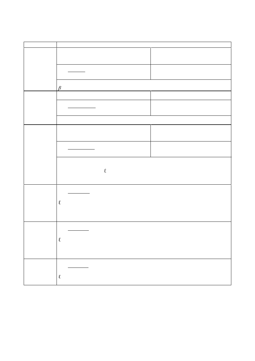
SU(1(
7DEOH6WLIIQHVVFRHIILFLHQWVIRUEDVLFMRLQWFRPSRQHQWV
Component Stiffness
coefficient
N
i
Unstiffened,
single-sided joint, or a double-sided joint in
which the beam depths are similar
stiffened
N
1
=
]
$
9&
β
38
,
0
N
1
=
&ROXPQZHE
SDQHOLQVKHDU
]
is
the lever arm from Figure 6.15;
is
the transformation parameter from 5.3(7).
unstiffened stiffened
N
2
=
F
ZF
ZF
F
HII
G
W
E
,
,
7
,
0
N
2
=
&ROXPQZHELQ
FRPSUHVVLRQ
E
eff,c,wc
is the effective width from 6.2.6.2
stiffened or unstiffened bolted connection with
a single bolt-row in tension or unstiffened
welded connection
stiffened welded connection
N
3
=
F
ZF
ZF
W
HII
G
W
E
,
,
7
,
0
N
3
=
&ROXPQZHELQ
WHQVLRQ
E
eff,t,wc
is the effective width of the column web in tension from 6.2.6.3. For a joint with a
single bolt-row in tension,
E
eff,t,wc
should be taken as equal to the smallest of the
effective lengths
eff
(individually or as part of a group of bolt-rows) given for this
bolt-row in Table 6.4 (for an unstiffened column flange) or Table 6.5 (for a
stiffened column flange).
&ROXPQIODQJH
LQEHQGLQJ
(for a single
bolt-row in
tension)
N
4
=
3
3
9
,
0
P
W
IF
HII
"
eff
is the smallest of the effective lengths (individually or as part of a bolt group) for
this bolt-row given in Table 6.4 for an unstiffened column flange or Table 6.5 for a
stiffened column flange;
P
is as defined in Figure 6.8;
(QGSODWHLQ
EHQGLQJ
(for a single
bolt-row in
tension)
N
5
=
3
3
9
,
0
P
W
S
HII
"
eff
is the smallest of the effective lengths (individually or as part of a group of bolt-
rows) given for this bolt-row in Table 6.6;
P
is generally as defined in Figure 6.11, but for a bolt-row located in the extended part
of an extended end-plate
P = P
x
, where
P
x
is as defined in Figure 6.10.
)ODQJHFOHDWLQ
EHQGLQJ
N
6
=
3
3
9
,
0
P
W
D
HII
"
eff
is the effective length of the flange cleat from Figure 6.12;
P
is as defined in Figure 6.13.

SU(1(
Component Stiffness
coefficient
N
i
%ROWVLQWHQVLRQ
(for a single
bolt-row)
N
10
=
E
V
/
$ /
6
,
1
preloaded
or
non-preloaded
/
b
is the bolt elongation length, taken as equal to the grip length (total thickness of
material and washers), plus half the sum of the height of the bolt head and the
height of the nut.
non-preloaded preloaded
*)
N
11
(or
N
17
) =
16
2
16
0
XE
E
(G
I
G
Q
N
11
=
%ROWVLQVKHDU
G
M16
is the nominal diameter of an M16 bolt;
Q
b
is the number of bolt-rows in shear.
non-preloaded preloaded
*)
N
12
(or
N
18
) =
(
I
G
N
N
Q
X
W
E
E
24
N
12
=
%ROWVLQ
EHDULQJ
(for each
component
M
on which the
bolts bear)
N
b
=
N
b1
but
N
b
N
b2
N
b1
= 0,25
H
b
/
G + 0,5
but
N
b1
N
b2
= 0,25
S
b
/
G + 0,375
but
N
b2
N
t
= 1,5
W
j
/
G
M16
but
N
t
H
b
is the distance from the bolt-row to the free
edge of the plate in the direction of load
transfer;
I
u
is the ultimate tensile strength of the steel on
which the bolt bears;
S
b
is the spacing of the bolt-rows in the direction
of load transfer;
W
j
is the thickness of that component.
&RQFUHWHLQ
FRPSUHVVLRQ
(including
grout)
N
13
=
(
O
E
(
HII
HII
F
275
,
1
E
eff
is the effective width of the T-stub flange, see 6.2.5(3);
O
eff
is the effective length of the T-stub flange, see 6.2.5(3).
3ODWHLQ
EHQGLQJXQGHU
FRPSUHVVLRQ
N
14
=
This coefficient is already taken into consideration in the calculation of the stiffness
coefficient k
13
with prying forces
**)
without prying forces
**)
N
15
=
3
3
85
,
0
P
W
S
HII
"
N
15
=
3
3
425
,
0
P
W
S
HII
"
%DVHSODWHLQ
EHQGLQJXQGHU
WHQVLRQ
(for a single
bolt row in
tension)
O
eff
is the effective length of the T-stub flange, see 6.2.5(3);
W
p
is the thickness of the base plate;
P
is the distance according to Figure 6.8.
with prying forces
**)
without prying forces
**)
N
16
=
E
V
/
$ /
6
,
1
N
16
=
E
V
/
$ /
0
,
2
$QFKRUEROWVLQ
WHQVLRQ
L
b
is the anchor bolt elongation length, taken as equal to the sum of 8 times the
nominal bolt diameter, the grout layer, the plate thickness, the washer and half of
the height of the nut.
*)
provided that the bolts have been designed not to slip into bearing at the load level concerned
**)
prying forces may develop, if
/
b
3
3
8
,
8
W
O
$
P
HII
V

SU(1(
127( When calculating E
eff
and
O
eff
the distance
F should be taken as 1,25 times the base plate
thickness.
127(Backing plates should be assumed not to affect the rotational stiffness 6
j
of the joint.
127(For ZHOGV (N
19
) the stiffness coefficient should be taken as equal to infinity. This
component need not be taken into account when calculating the rotational stiffness
6
j
.
127(For EHDPIODQJHDQGZHELQFRPSUHVVLRQ (N
7
),
EHDPZHELQWHQVLRQ (N
8
),
SODWHLQWHQVLRQ
RU FRPSUHVVLRQ (N
9
),
KDXQFKHG EHDPV (N
20
), the stiffness coefficients should be taken as equal to
infinity. These components need not be taken into account when calculating the rotational stiffness
6
j
.
127(Where a VXSSOHPHQWDU\ZHESODWH is used, the stiffness coefficients for the relevant basic
joint components
N
1
to
N
3
should be increased as follows:
–
N
1
for the column web panel in shear should be based on the increased shear area
$
vc
from
6.2.6.1(6);
–
N
2
for the column web in compression should be based on the effective thickness of the web
from 6.2.6.2(6);
–
N
3
for the column web in tension, should be based on the effective thickness of the web from
6.2.6.3(8).
(QGSODWHFRQQHFWLRQVZLWKWZRRUPRUHEROWURZVLQWHQVLRQ
*HQHUDOPHWKRG
(1)
For end-plate connections with two or more bolt-rows in tension, the basic components related to all
of these bolt-rows should be represented by a single equivalent stiffness coefficient
N
eq
determined
from:
N
eq
=
HT
U
U
U
HII
]
K
N
∑
,
... (6.29)
where:
K
U
is
the distance between bolt-row
U and the centre of compression;
N
eff,
U
is
the effective stiffness coefficient for bolt-row
U taking into account the stiffness coefficients
N
L
for the basic components listed in 6.3.3.1(4) or 6.3.3.1(5) as appropriate;
]
eq
is
the equivalent lever arm, see 6.3.3.1(3).
(2)
The effective stiffness coefficient
N
eff,
U
for bolt-row
U should be determined from:
N
eff,
U
=
∑
L
U
L
N
,
1
1
...
(6.30)
where:
N
LU
is
the stiffness coefficient representing component
L relative to bolt-row U
.
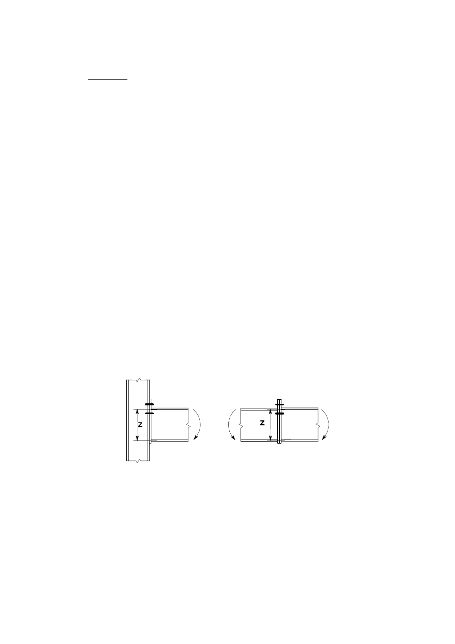
SU(1(
(3)
The equivalent lever arm
]
eq
should be determined from:
]
eq
=
∑
∑
U
U
U
HII
U
U
U
HII
K
N
K
N
,
2
,
...
(6.31)
(4)
In the case of a beam-to-column joint with an end-plate connection,
N
eq
should be based upon (and
replace) the stiffness coefficients
N
L
for:
–
the column web in tension (
N
3
);
–
the column flange in bending (
N
4
);
–
the end-plate in bending (
N
5
);
–
the bolts in tension (
N
10
).
(5)
In the case of a beam splice with bolted end-plates,
N
eq
should be based upon (and replace) the
stiffness coefficients
N
L
for:
–
the end-plates in bending (
N
5
);
–
the bolts in tension (
N
10
).
6LPSOLILHGPHWKRGIRUH[WHQGHGHQGSODWHVZLWKWZREROWURZVLQWHQVLRQ
(1)
For extended end-plate connections with two bolt-rows in tension, (one in the extended part of the
end-plate and one between the flanges of the beam, see Figure 6.20), a set of modified values may be
used for the stiffness coefficients of the related basic components to allow for the combined
contribution of both bolt-rows. Each of these modified values should be taken as twice the
corresponding value for a single bolt-row in the extended part of the end-plate.
127(This approximation leads to a slightly lower estimate of the rotational stiffness.
(2)
When using this simplified method, the lever arm
] should be taken as equal to the distance from the
centre of compression to a point midway between the two bolt-rows in tension, see Figure 6.20.
)LJXUH/HYHUDUP]IRUVLPSOLILHGPHWKRG
&ROXPQEDVHV
(1)
The rotational stiffness,
6
j
, of a column base subject to combined axial force and bending moment
should be calculated using the method given in Table 6.12. This method uses the following stiffness
coefficients:
N
T,l
is
the tension stiffness coefficient of the left hand side of the joint and should be taken as equal
to the sum of the stiffness coefficients
N
15
and
N
16
(given in Table 6.11) acting on the left hand
side of the joint.

SU(1(
N
T,r
is the tension stiffness coefficient of the right hand side of the joint and should be taken as
equal to the sum of the stiffness coefficients
N
15
and
N
16
(given in Table 6.11) acting on the right
hand side of the joint.
N
C,l
is
the compression stiffness coefficient of the left hand side of the joint and should be taken as
equal to the stiffness coefficient
N
13
(given in Table 6.11) acting on the left hand side of the joint.
N
C,r
is
the compression stiffness coefficient of the right hand side of the joint and should be taken as
equal to the stiffness coefficient
N
13
(given in Table 6.11) acting on the right hand side of the joint.
(2)
For the calculation of z
T,l
, z
C,l,
z
T,r,
z
C,r
see 6.2.8.1.
7DEOH5RWDWLRQDOVWLIIQHVV6
M
RIFROXPQEDVHV
Loading
Lever arm
] Rotational
stiffness
6
j,ini
]= ]
T,l
+ ]
C,r
1
Ed
> 0 and
H > ]
T,l
1
Ed
and
H -]
C,r
Left side in tension
Right side in compression
N
U
&
7
H
H
H
N
N
]
(
+
+
)
/
1
/
1
(
,
1
,
2
µ
where
H
k
=
U
&
7
7
7
U
&
U
&
N
N
N
]
N
]
,
1
,
1
,
1
,
,
,
+
−
]= ]
T,l
+ ]
T,r
1
Ed
> 0 and
0 <
H < ]
T,l
1
Ed
> 0 and
-
]
T,r
<
H
Left side in tension
Right side in tension
N
U
7
7
H
H
H
N
N
(]
+
+
)
/
1
/
1
(
,
1
,
2
µ
where
H
k
=
U
7
7
7
7
U
7
U
7
N
N
N
]
N
]
,
1
,
1
,
1
,
,
,
+
−
]= ]
C,l
+ ]
T,r
1
Ed
> 0 and
H -]
T,r
1
Ed
and
H > ]
C,l
Left side in compression
Right side in tension
N
U
7
&
H
H
H
N
N
(]
+
+
)
/
1
/
1
(
,
1
,
2
µ
where
H
k
=
U
7
&
&
&
U
7
U
7
N
N
N
]
N
]
,
1
,
1
,
1
,
,
,
+
−
]= ]
C,l
+ ]
C,r
1
Ed
and
0 <
H < ]
C,l
1
Ed
and
-
]
C,r
<
H
Left side in compression
Right side in compression
U
&
&
H
H
H
N
N
(]
+
+
)
/
1
/
1
(
,
1
,
2
µ
where
H
k
=
U
&
&
&
&
U
&
U
&
N
N
N
]
N
]
,
1
,
1
,
1
,
,
,
+
−
0
Ed
> 0 is clockwise,
1
Ed
> 0 is tension,
see 6.3.1(6).
H =
(G
(G
1
0
=
5G
5G
1
0
5RWDWLRQFDSDFLW\
*HQHUDO
(1)
In the case of rigid plastic global analysis, a joint at a plastic hinge location should have sufficient
rotation capacity.
(2)
The rotation capacity of a bolted or welded joint should be determined using the provisions given in
6.4.2 or 6.4.3. The design methods given in these clauses are only valid for S235, S275 and S355 steel
grades and for joints in which the axial force
1
Ed
in the connected member does not exceed 5% of the
design plastic resistance
1
p
5G
of its cross-section.
(3)
As an alternative to 6.4.2 and 6.4.3 the rotation capacity of a joint need not be checked provided that
the design moment resistance
0
j,Rd
of the joint is at least 1.2 times the design plastic moment
resistance
0
pl,Rd
of the connected member.

SU(1(
(4) In cases not covered by 6.4.2 and 6.4.3 the rotation capacity may be determined by testing in
accordance with EN 1990, Annex D. Alternatively, appropriate calculation models may be used,
provided that they are based on the results of tests in accordance with EN1990.
%ROWHGMRLQWV
(1)
A beam-to-column joint in which the design moment resistance of the joint
0
j,Rd
is governed by the
design resistance of the column web panel in shear, may be assumed to have adequate rotation
capacity for plastic global analysis, provided that
G/W
w
.
(2)
A joint with either a bolted end-plate or angle flange cleat connection may be assumed to have
sufficient rotation capacity for plastic analysis, provided that both of the following conditions are
satisfied:
a) the design moment resistance of the joint is governed by the design resistance of either:
–
the column flange in bending or
–
the beam end-plate or tension flange cleat in bending.
b) the
thickness
W of either the column flange or the beam end-plate or tension flange cleat (not
necessarily the same basic component as in (a)) satisfies:
W
\
XE
I
I
G
/
36
,
0
...
(6.32)
where:
I
y
is
the yield strength of the relevant basic component.
(3) A joint with a bolted connection in which the design moment resistance
0
j,Rd
is governed by the
design resistance of its bolts in shear, should not be assumed to have sufficient rotation capacity for
plastic global analysis.
:HOGHG-RLQWV
(1) The
rotation
capacity
φ
Cd
of a welded beam-to-column connection may be assumed to be not less that
the value given by the following expression provided that its column web is stiffened in compression
but unstiffened in tension, and its design moment resistance is not governed by the design shear
resistance of the column web panel, see 6.4.2(1):
φ
Cd
= 0,025
K
c
/
K
b
... (6.33)
where:
K
b
is
the depth of the beam;
K
c
is
the depth of the column.
(2)
An unstiffened welded beam-to-column joint designed in conformity with the provisions of this
section, may be assumed to have a rotation capacity
φ
Cd
of at least 0,015 radians.

SU(1(
+ROORZVHFWLRQMRLQWV
*HQHUDO
6FRSH
(1)
This section gives detailed application rules to determine the static design resistances of uniplanar and
multiplanar joints in lattice structures composed of circular, square or rectangular hollow sections, and
of uniplanar joints in lattice structures composed of combinations of hollow sections with open
sections.
(2)
The static design resistances of the joints are expressed in terms of maximum design axial and/or
moment resistances for the brace members.
(3)
These application rules are valid both for hot finished hollow sections to EN 10210 and for cold
formed hollow sections to EN 10219, if the dimensions of the structural hollow sections fulfil the
requirements of this section.
(4)
For hot finished hollow sections and cold formed hollow sections the nominal yield strength of the end
product should not exceed 460 N/mm
2
. For end products with a nominal yield strength higher than 355
N/mm
2
, the static design resistances given in this section should be reduced by a factor 0,9.
(5)
The nominal wall thickness of hollow sections should not be less than 2,5 mm.
(6)
The nominal wall thickness of a hollow section chord should not be greater than 25 mm unless special
measures have been taken to ensure that the through thickness properties of the material will be
adequate.
(7)
For fatigue assessment see EN 1993-1-9.
(8)
The types of joints covered are indicated in Figure 7.1.
)LHOGRIDSSOLFDWLRQ
(1)
The application rules for hollow section joints may be used only where all of the conditions given in
7.1.2(2) to 7.1.2(8) are satisfied.
(2)
The compression elements of the members should satisfy the requirements for Class 1 or Class 2 given
in EN 1993-1-1 for the condition of pure bending.
(3) The
angles
i
between the chords and the brace members, and between adjacent brace members,
should satisfy:
i
(4)
The ends of members that meet at a joint should be prepared in such a way that their cross-sectional
shape is not modified. Flattened end connections and cropped end connections are not covered in this
section.
(5)
In gap type joints, in order to ensure that the clearance is adequate for forming satisfactory welds, the
gap between the brace members should not be less than (
W
1
+
W
2
).
(6)
In overlap type joints, the overlap should be large enough to ensure that the interconnection of the
brace members is sufficient for adequate shear transfer from one brace to the other. In any case the
overlap should be at least 25%.
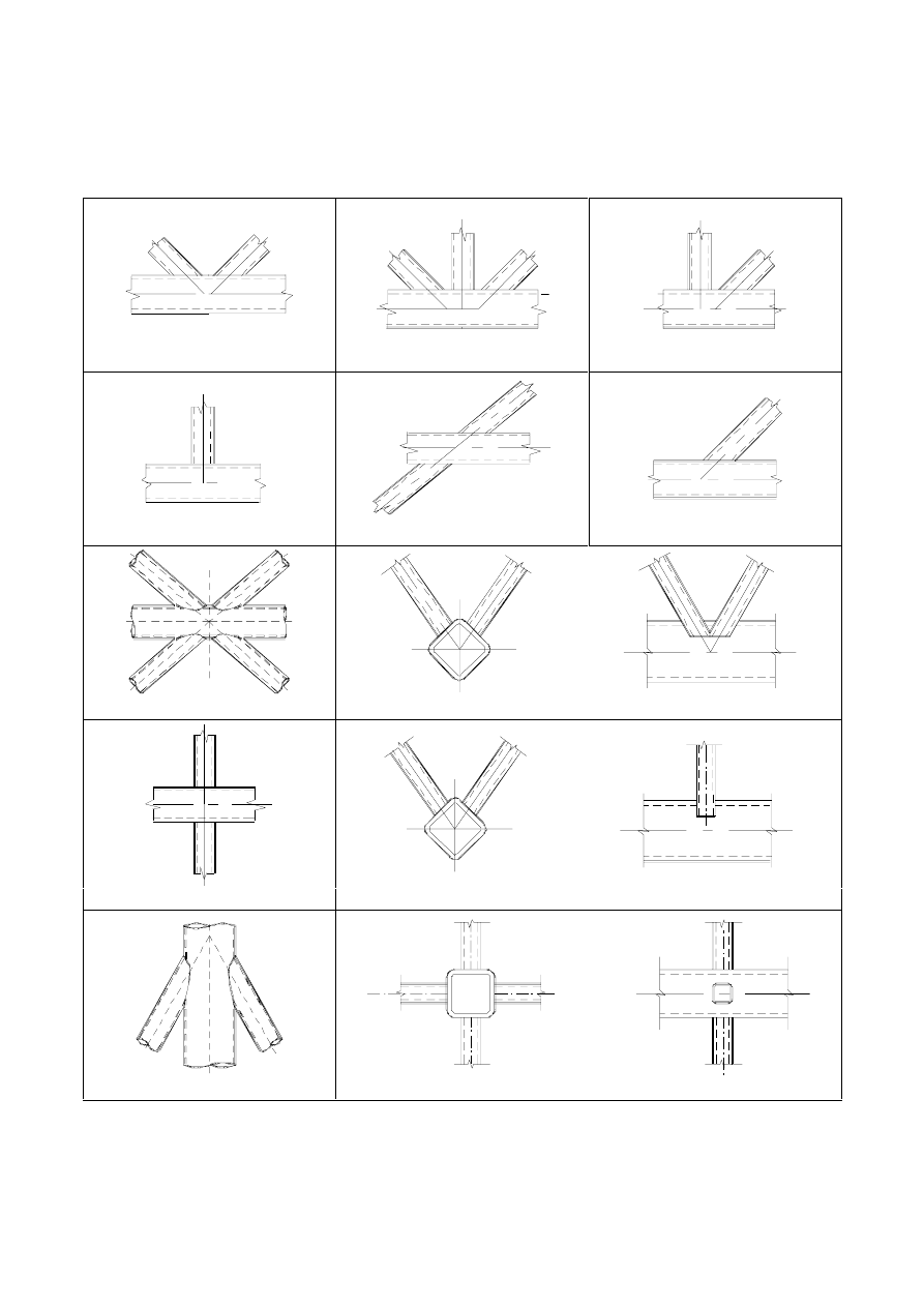
SU(1(
(7)
Where overlapping brace members have different thicknesses and/or different strength grades, the
member with the lowest
W
i
I
yi
value should overlap the other member.
(8)
Where overlapping brace members are of different widths, the narrower member should overlap the
wider one.
K joint
KT joint
N joint
T joint
X joint
Y joint
DK joint
KK joint
X joint
TT joint
DY joint
XX joint
)LJXUH7\SHVRIMRLQWVLQKROORZVHFWLRQODWWLFHJLUGHUV

SU(1(
'HVLJQ
*HQHUDO
(1)
The design values of the internal axial forces both in the brace members and in the chords at the
ultimate limit state should not exceed the design resistances of the members determined from
EN 1993-1-1.
(2)
The design values of the internal axial forces in the brace members at the ultimate limit state should
also not exceed the design resistances of the joints given in 7.4, 7.5 or 7.6 as appropriate.
(3)
The stresses
0,Ed
or
p,Ed
in the chord at a joint should be determined from:
0,Ed
=
0
(,
,
0
0
,
0
H
(G
(G
:
0
$
1
+
...
(7.1)
p,Ed
=
0
(,
,
0
0
,
H
(G
(G
S
:
0
$
1
+
...
(7.2)
where:
1
p,Ed
=
∑
>
−
0
,
,
0
cos
L
L
(G
L
(G
1
1
θ
)DLOXUHPRGHVIRUKROORZVHFWLRQFRQQHFWLRQV
(1)
The design joint resistances of connections between hollow sections and of connections between
hollow sections and open sections, should be based on the following failure modes as applicable:
a)
&KRUGIDFHIDLOXUH (plastic failure of the chord face) or chord plastification (plastic failure of
the chord cross-section);
b)
&KRUGVLGHZDOOIDLOXUH (or FKRUGZHEIDLOXUH) by yielding, crushing or instability (crippling
or buckling of the chord side wall or chord web) under the compression brace member;
c)
&KRUGVKHDUIDLOXUH;
d)
3XQFKLQJVKHDU failure of a hollow section chord wall (crack initiation leading to rupture of the
brace members from the chord member);
e)
%UDFHIDLOXUH with reduced effective width (cracking in the welds or in the brace members);
f)
/RFDO EXFNOLQJ failure of a brace member or of a hollow section chord member at the joint
location.
127(The phrases printed in boldface type in this list are used to describe the various failure modes
in the tables of design resistances given in 7.4 to 7.6.
(2)
Figure 7.2 illustrates failure modes (a) to (f) for joints between CHS brace and chord members.
(3)
Figure 7.3 illustrates failure modes (a) to (f) for joints between RHS brace and chord members.
(4)
Figure 7.4 illustrates failure modes (a) to (f) for joints between CHS or RHS brace members and I or H
section chord members.
(5)
Although the resistance of a joint with properly formed welds is generally higher under tension than
under compression, the design resistance of the joint is generally based on the resistance of the brace
in compression to avoid the possible excessive local deformation or reduced rotation capacity or
deformation capacity which might otherwise occur.
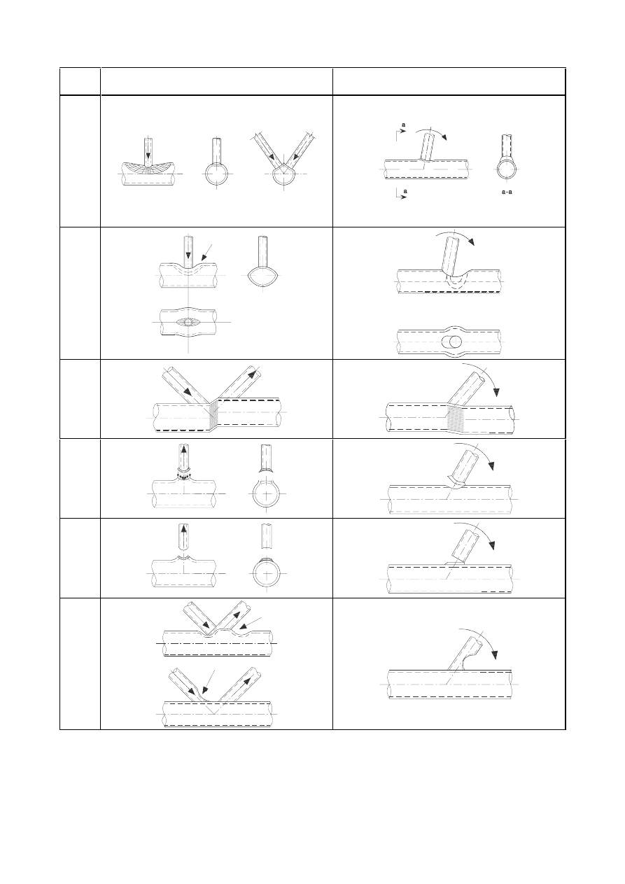
SU(1(
Mode
Axial loading
Bending moment
a
b
c
d
e
f
)LJXUH)DLOXUHPRGHVIRUMRLQWVEHWZHHQ&+6PHPEHUV
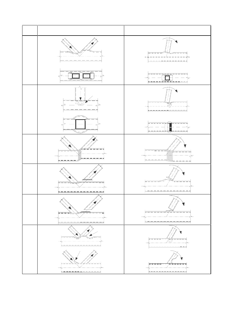
SU(1(
Mode
Axial loading
Bending moment
a
b
c
d
e
f
)LJXUH)DLOXUHPRGHVIRUMRLQWVEHWZHHQ5+6EUDFHPHPEHUVDQG5+6FKRUG
PHPEHUV
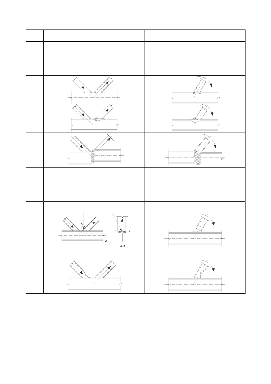
SU(1(
Mode
Axial loading
Bending moment
a
–
–
b
c
d
–
–
e
f
)LJXUH)DLOXUHPRGHVIRUMRLQWVEHWZHHQ&+6RU5+6EUDFHPHPEHUVDQG,
RU+VHFWLRQFKRUGPHPEHUV
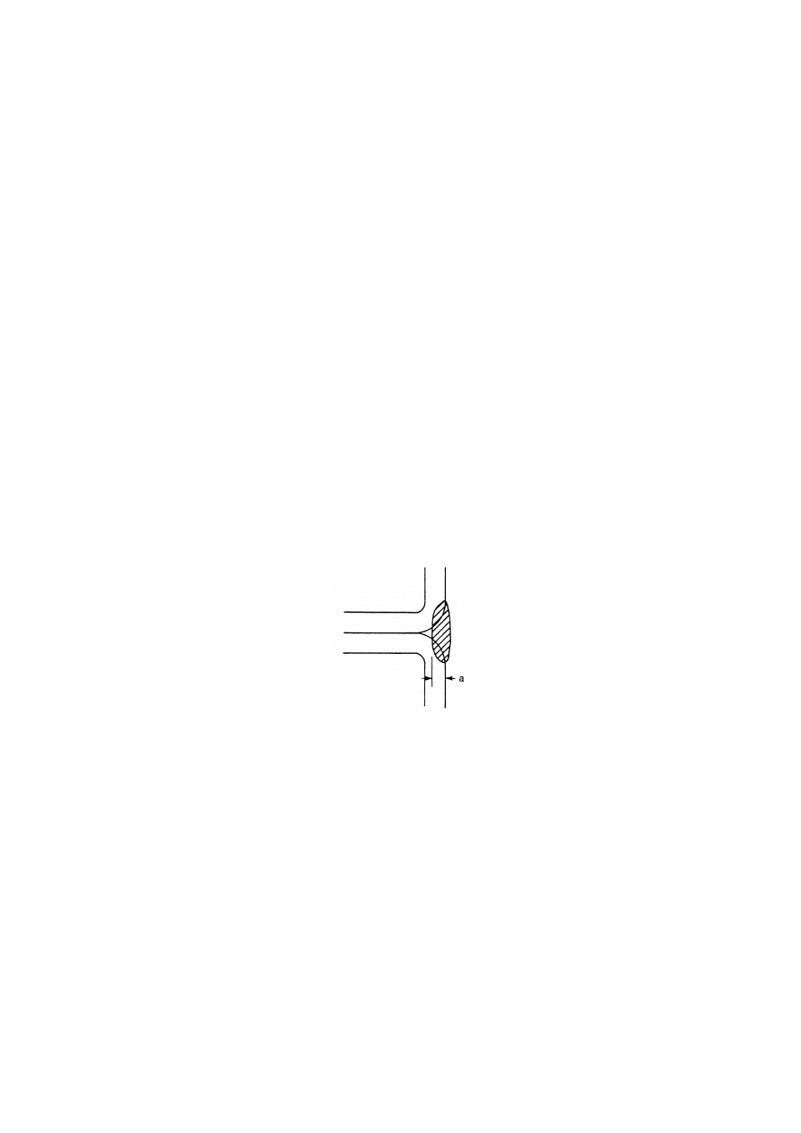
SU(1(
:HOGV
'HVLJQUHVLVWDQFH
(1) The welds connecting the brace members to the chords should be designed to have sufficient
resistance to allow for non-uniform stress-distributions and sufficient deformation capacity to allow
for redistribution of bending moments.
(2)
In welded joints, the connection should normally be formed around the entire perimeter of the hollow
section by means of a butt weld, a fillet weld, or combinations of the two. However in partially
overlapping joints the hidden part of the connection need not be welded, provided that the axial forces
in the brace members are such that their components perpendicular to the axis of the chord do not
differ by more than 20%.
(3)
Typical weld details are indicated in 2.8 Reference Standards: Group 7.
(4)
The design resistance of the weld, per unit length of perimeter of a brace member, should not normally
be less than the design resistance of the cross-section of that member per unit length of perimeter.
(5)
The required throat thickness should be determined from section 4.
(6)
The criterion given in 7.3.1(4) may be waived where a smaller weld size can be justified both with
regard to resistance and with regard to deformation capacity and rotation capacity, taking account of
the possibility that only part of its length is effective.
(7)
For rectangular structural hollow sections the design throat thickness of flare groove welds is defined
in Figure 7.5.
)LJXUH'HVLJQWKURDWWKLFNQHVVRIIODUHJURRYHZHOGVLQUHFWDQJXODU
VWUXFWXUDOKROORZVHFWLRQ
(8)
For welding in cold-formed zones, see 4.14.

SU(1(
:HOGHGMRLQWVEHWZHHQ&+6PHPEHUV
*HQHUDO
(1)
Provided that the geometry of the joints is within the range of validity given in Table 7.1, the design
resistances of welded joints between circular hollow section members should be determined using
7.4.2 and 7.4.3.
(2)
For joints within the range of validity given in Table 7.1, only chord face failure and punching shear
need be considered. The design resistance of a connection should be taken as the minimum value for
these two criteria.
(3)
For joints outside the range of validity given in Table 7.1, all the criteria given in 7.2.2 should be
considered. In addition, the secondary moments in the joints caused by their rotational stiffness
should be taken into account.
7DEOH5DQJHRIYDOLGLW\IRUZHOGHGMRLQWVEHWZHHQ&+6EUDFHPHPEHUVDQG
&+6FKRUGV
0,2
G
i
/
G
0
1,0
Class 2 and
10
G
0
/
W
0
50 generally
but
10
G
0
/
W
0
40
for X joints
Class 2 and
10
G
i
/
W
i
50
ov
25%
J
W
1
+
W
2
8QLSODQDUMRLQWV
(1)
In brace member connections subject only to axial forces, the design internal axial force
1
i,Ed
should
not exceed the design axial resistance of the welded joint
1
i,Rd
obtained from Table 7.2, Table 7.3 or
Table 7.4 as appropriate.
(2)
Brace member connections subject to combined bending and axial force should satisfy:
5G
L
RS
(G
L
RS
5G
L
LS
(G
L
LS
5G
L
(G
L
0
0
0
0
1
1
,
,
,
,
2
,
,
,
,
,
,
+
+
...
(7.3)
where:
0
ip,i,Rd
is the design in-plane moment resistance;
0
ip,i,Ed
is the design in-plane internal moment;
0
op,i,Rd
is the design out-of-plane moment resistance;
0
op,i,Ed
is the design out-of-plane internal moment.
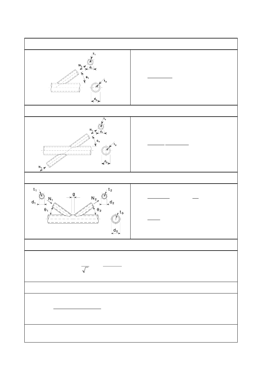
SU(1(
7DEOH'HVLJQD[LDOUHVLVWDQFHVRIZHOGHGMRLQWVEHWZHHQ&+6EUDFH
PHPEHUVDQG&+6FKRUGV
Chord face failure -
T and Y joints
1
1,Rd
=
5
2
1
2
0
0
2
,
0
/
)
2
,
14
8
,
2
(
sin
0
\
S
W
I
N
γ
β
θ
γ
+
Chord face failure -
X joints
1
1,Rd
=
5
1
2
0
0
/
)
81
,
0
1
(
2
,
5
sin
0
\
S
W
I
N
γ
β
θ
−
Chord face failure -
K and N gap or overlap joints
1
1,Rd
=
5
0
1
1
2
0
0
/
2
,
10
8
,
1
sin
0
\
S
J
G
G
W
I
N
N
γ
θ
+
1
2,Rd
=
5G
1
,
1
2
1
sin
sin
θ
θ
Punching shear failure - K, N and KT gap joints and all T, Y and X joints
[
L = 1, 2 or 3]
When
G
i
G
0
íW
0
:
1
i,Rd
=
5
2
0
0
/
sin
2
sin
1
3
0
L
L
L
\
G
W
I
γ
θ
θ
π
+
Factors
N
g
and
N
p
N
g
=
(
)
−
+
+
33
,
1
/
5
,
0
exp
1
024
,
0
1
0
2
,
1
2
,
0
W
J
γ
γ
(see
Figure
7.6)
For
Q
p
> 0 (compression):
N
p
= 1
íQ
p
(1 +
Q
p
)
but
N
p
For
Q
p
WHQVLRQ
N
p
= 1,0

SU(1(
7DEOH'HVLJQUHVLVWDQFHVRIZHOGHGMRLQWVFRQQHFWLQJJXVVHWSODWHVWR&+6
PHPEHUV
Chord face failure
1
i,Rd
=
5
2
2
0
0
/
)
20
4
(
0
\
S
W
I
N
γ
β
+
0
ip,i,Rd
= 0
0
op,i,Rd
= 0,5
E
i
1
i,Rd
1
i,Rd
=
5
2
0
0
/
81
,
0
1
5
0
\
S
W
I
N
γ
β
−
0
ip,i,Rd
= 0
0
op,i,Rd
= 0,5
E
i
1
i,Rd
1
i,Rd
=
(
)
5
2
0
0
/
25
,
0
1
5
0
\
S
W
I
N
γ
η
+
0
ip,i,Rd
=
K
i
1
i,Rd
0
op,i,Rd
= 0
1
i,Rd
=
(
)
5
2
0
0
/
25
,
0
1
5
0
\
S
W
I
N
γ
η
+
0
ip,i,Rd
=
K
i
1
i,Rd
0
op,i,Rd
= 0
Punching shear failure
L
W
max
σ
=
L
HO
(G
(G
W
:
0
$
1
)
/
/
(
+
5
0
0
/
)
3
/
(
2
0
\
I
W
γ
Range of validity
Factor
N
p
In addition to the limits given in Table 7.1:
and
where
=
E
i
/
G
0
and
=
K
i
/
G
0
For
Q
p
> 0 (compression):
N
p
= 1
íQ
p
(1 +
Q
p
) but
N
p
For
Q
p
WHQVLRQ
N
p
= 1,0
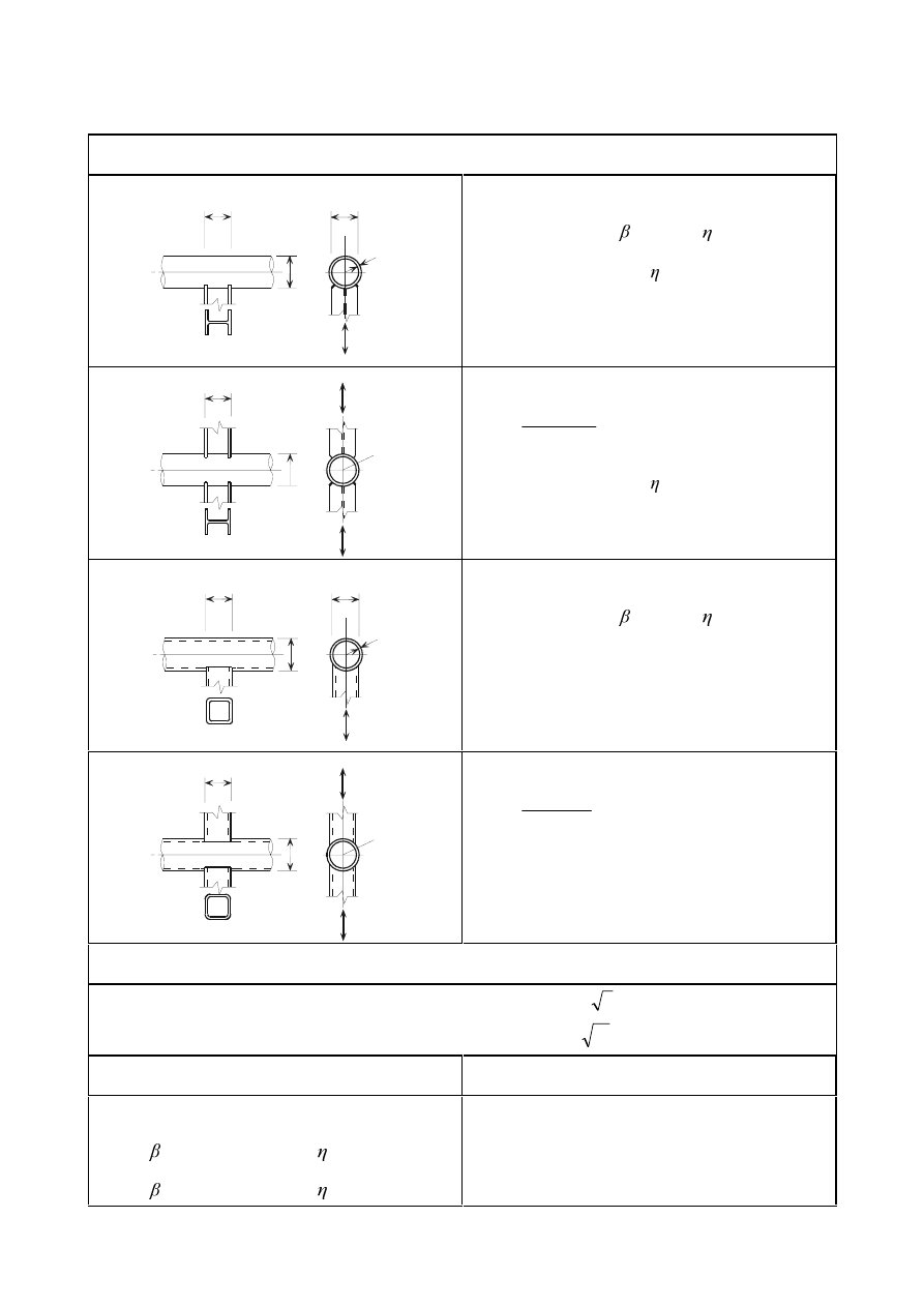
SU(1(
7DEOH'HVLJQUHVLVWDQFHVRIZHOGHGMRLQWVFRQQHFWLQJ,+RU5+6VHFWLRQVWR
&+6PHPEHUV
Chord face failure
1
h
d
1
N
0
1
b
t
0
1
1,Rd
=
N
p
I
y0
W
0
2
(4 + 20
2
)(1 + 0,25 ) /
γ
M5
0
ip,1,Rd
=
K
1
1
1,Rd
/(1 + 0,25 )
0
op,1,Rd
= 0,5
E
1
1
1,Rd
1
N
1
N
1
h
d
0
t
0
1
1,Rd
=
(
)
5
2
0
0
/
25
,
0
1
81
,
0
1
5
0
\
S
W
I
N
γ
η
β
+
−
0
ip,1,Rd
=
K
1
1
1,Rd
/(1 + 0,25 )
0
op,1,Rd
= 0,5
E
1
1
1,Rd
1
N
1
h
d
0
1
b
t
0
1
1,Rd
=
N
p
I
y0
W
0
2
(4 + 20
2
)(1 + 0,25 )/
γ
M5
0
ip,1,Rd
=
K
1
1
1,Rd
0
op,1,Rd
= 0,5
E
1
1
1,Rd
1
N
1
N
1
h
d
0
t
0
1
1,Rd
=
(
)
5
2
0
0
/
25
,
0
1
81
,
0
1
5
0
\
S
W
I
N
γ
η
β
+
−
0
ip,1,Rd
=
K
1
1
1,Rd
0
op,1,Rd
= 0,5
E
1
1
1,Rd
Punching shear failure
I or H sections:
1
max
W
σ
=
(
)
1
(
/
/
W
:
0
$
1
H
(G
(G
+
5
0
0
/
)
3
/
(
2
0
\
I
W
γ
RHS sections:
1
max
W
σ
=
(
)
1
(
/
/
W
:
0
$
1
H
(G
(G
+
5
0
0
/
)
3
/
(
0
\
I
W
γ
Range of validity
Factor
N
p
In addition to the limits given in Table 7.1:
and
where
=
E
1
/ d
0
and =
K
1
/
G
0
For
Q
p
> 0 (compression):
N
p
= 1
íQ
p
(1 +
Q
p
) but
N
p
For
Q
p
Wension):
N
p
= 1,0
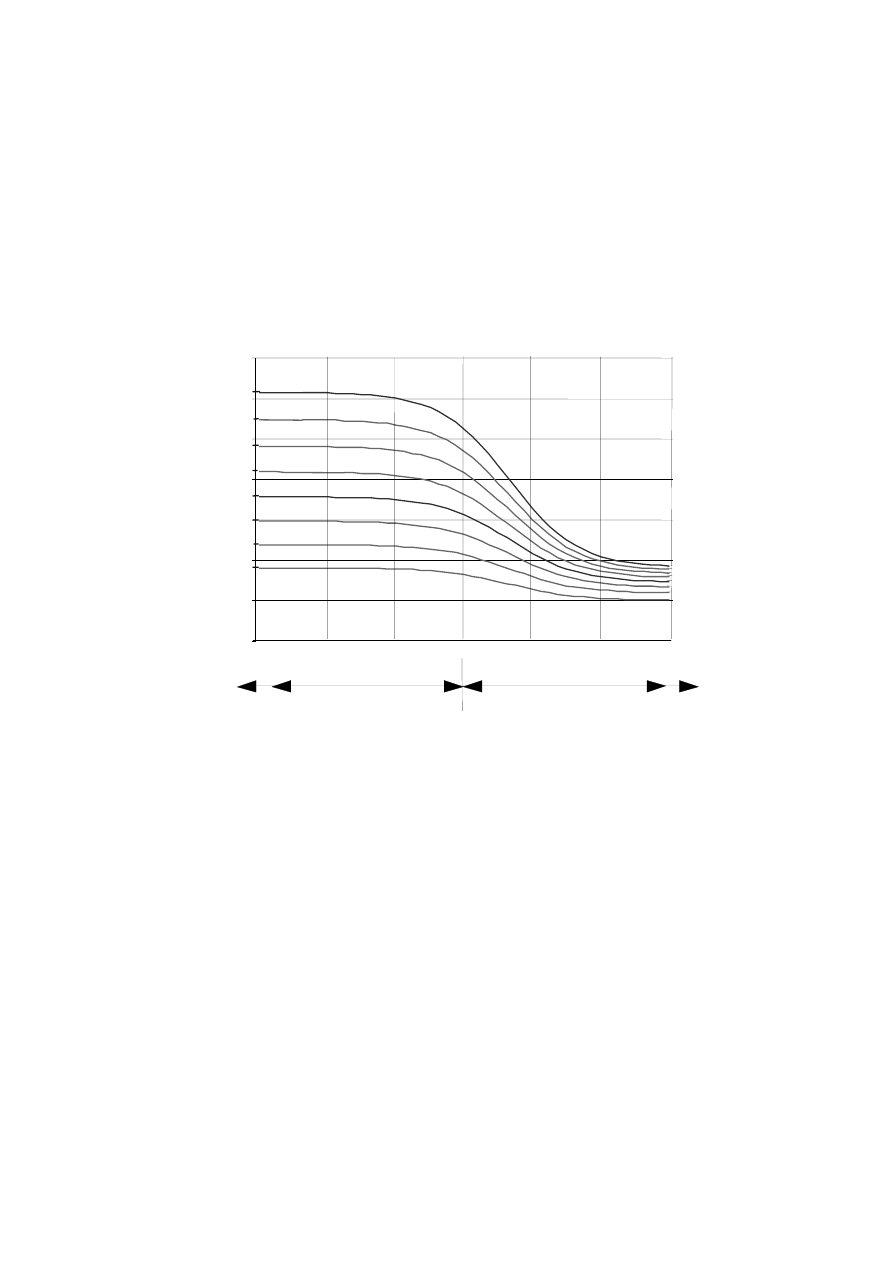
SU(1(
(3)
The design internal moment
0
i,Ed
may be taken as the value at the point where the centreline of the
brace member meets the face of the chord member.
(4)
The design in-plane moment resistance and the design out-of-plane moment resistance
0
i,Rd
should
be obtained from Table 7.3, Table 7.4 or Table 7.5 as appropriate.
(5)
The special types of welded joints indicated in Table 7.6 should satisfy the appropriate design criteria
specified for each type in that table.
(6)
Values of the factor
N
g
which is used in Table 7.2 for K, N and KT joints are given in Figure 7.6. The
factor
N
g
is used to cover both gap type and overlap type joints by adopting
J for both the gap and
the overlap and using negative values of
J to represent the overlap T as defined in Figure 1.3(b).
1.0
1.5
2.0
2.5
3.0
3.5
4.0
4.5
-12
-8
-4
0
4
8
12
,
,
,
,
,
,
,
,
k
g / t
0
g
γ
= 7,5
γ
= 10
γ
= 12,5
γ
= 15
γ
= 17,5
γ
= 20
γ
= 22,5
γ
= 25
2YHUODSW\SHMRLQWV
T J
*DSW\SHMRLQWV
)LJXUH9DOXHVRIWKHIDFWRUN
J
IRUXVHLQ7DEOH
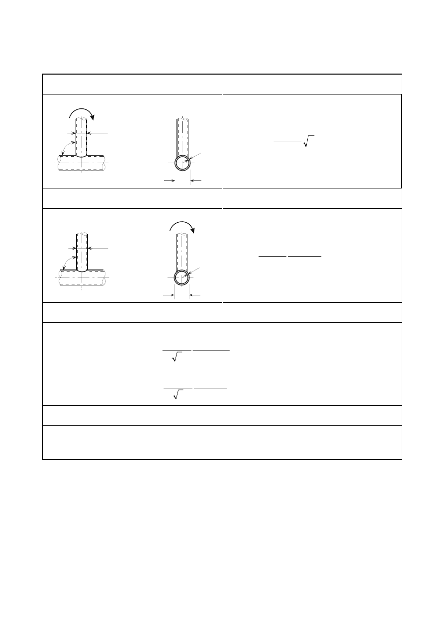
SU(1(
7DEOH'HVLJQUHVLVWDQFHPRPHQWVRIZHOGHGMRLQWVEHWZHHQ&+6EUDFH
PHPEHUVDQG&+6FKRUGV
Chord face failure -
T, X, and Y joints
d
M
1
1
d
t
0
0
ip,1
θ
0
ip,1,Rd
=
5
1
1
2
0
0
/
sin
85
,
4
0
S
\
N
G
W
I
γ
β
γ
θ
Chord face failure -
K, N, T, X and Y joints
d
1
1
d
t
0
0
M
op,1
θ
0
op,1,Rd
=
5
1
1
2
0
0
/
81
,
0
1
7
,
2
sin
0
S
\
N
G
W
I
γ
β
θ
−
Punching shear failure - K and N gap joints and all T, X and Y joints
When
G
1
G
0
íW
0
:
0
ip,1,Rd
=
5
1
2
1
2
1
0
0
/
sin
4
sin
3
1
3
0
\
G
W
I
γ
θ
θ
+
0
op,1,Rd
=
5
1
2
1
2
1
0
0
/
sin
4
sin
3
3
0
\
G
W
I
γ
θ
θ
+
Factor
N
p
For
Q
p
> 0 (compression):
N
p
= 1
íQ
p
(1 +
Q
p
) but
N
p
For
Q
p
WHQVLRQ
N
p
= 1,0
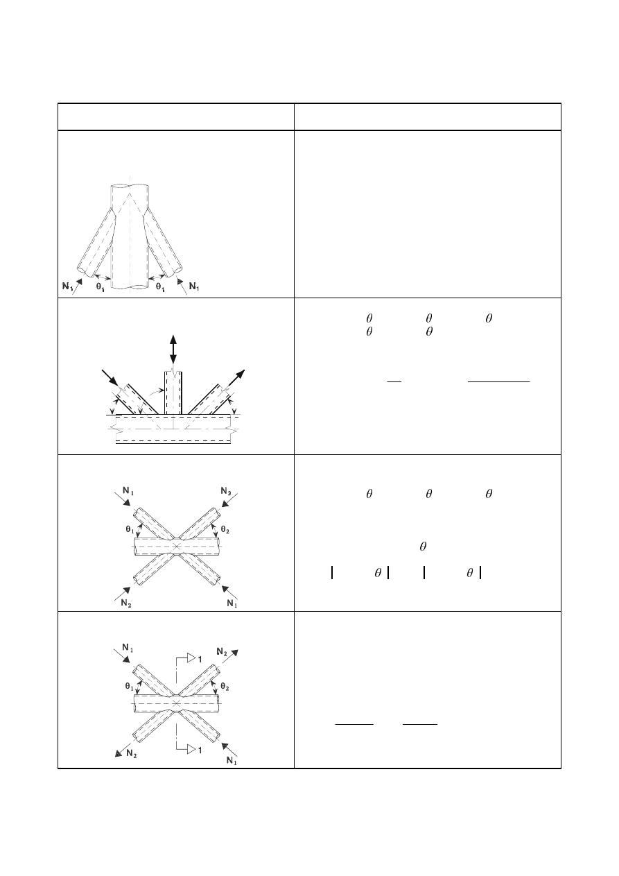
SU(1(
7DEOH'HVLJQFULWHULDIRUVSHFLDOW\SHVRIZHOGHGMRLQWVEHWZHHQ&+6EUDFH
PHPEHUVDQG&+6FKRUGV
Type of joint
Design criteria
The forces may be either tension or compression
but shall act in the same direction for both
members.
1
1,Ed
1
1,Rd
where
1
1,Rd
is the value of
1
1,Rd
for an X joint from
Table 7.2.
Member 1 is always in compression and
member 2 is always in tension.
N
3
N
N
1
2
3
1
2
θ
θ
θ
1
1,Ed
sin
1
+
1
3,Ed
sin
3
1
1,Rd
sin
1
1
2,Ed
sin
2
1
1,Rd
sin
1
where
1
1,Rd
is the value of
1
1,Rd
for a K joint from
Table 7.2 but with
0
1
G
G
replaced by:
0
3
2
1
3
G
G
G
G
+
+
All bracing members shall always be in either
compression or tension.
1
1,Ed
sin
1
+
1
2,Ed
sin
2
1
x,Rd
sin
x
where
1
x,Rd
is the value of
1
x,Rd
for an X joint from
Table 7.2, where
1
x,Rd
sin
x
is the larger of:
1
1,Rd
sin
1
DQG 1
2,Rd
sin
2
Member 1 is always in compression and member
2 is always in tension.
1
i,Ed
1
i,Rd
where
1
i,Rd
is the value of
1
i,Rd
for a K joint from
Table 7.2, provided that, in a gap-type joint, at section
1-1 the chord satisfies:
2
(,
,
0
,
0
2
(,
,
0
,
0
+
5G
S
(G
5G
S
(G
9
9
1
1
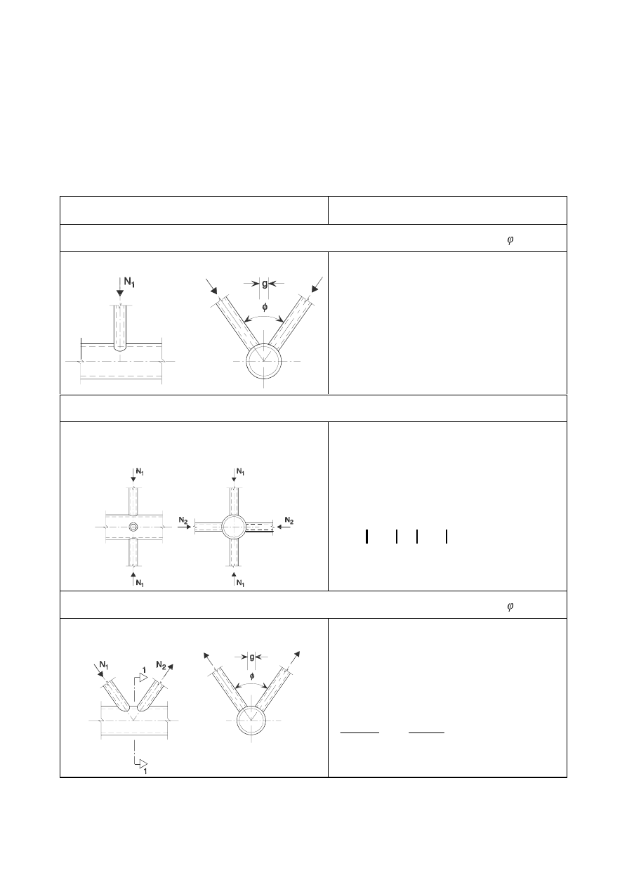
SU(1(
0XOWLSODQDUMRLQWV
(1)
In each relevant plane of a multiplanar joint, the design criteria given in 7.4.2 should be satisfied using
the reduced design resistances obtained from 7.4.3(2).
(2)
The design resistances for each relevant plane of a multiplanar joint should be determined by applying
the appropriate reduction factor
given in Table 7.7 to the resistance of the corresponding uniplanar
joint calculated according to 7.4.2 by using the appropriate chord force for
N
p
.
7DEOH5HGXFWLRQIDFWRUVIRUPXOWLSODQDUMRLQWV
Type of joint
Reduction factor
TT joint
60°
Member 1 may be either tension or compression.
= 1,0
XX joint
Members 1 and 2 can be either in compression or
tension.
1
2,Ed
/
1
1,Ed
is negative if one member is in
tension and one in compression.
=
(G
(G
1
1
,
1
,
2
/
33
,
0
1
+
taking account of the sign of
1
1,Ed
and
1
2,Ed
where
1
2,Ed
1
1,Ed
KK joint
60°
Member 1 is always in compression and member 2 is
always in tension.
= 0,9
provided that, in a gap-type joint, at section 1-1
the chord satisfies:
2
,
0
(,
,
0
2
,
0
(,
,
0
+
5G
S
(G
5G
S
(G
9
9
1
1
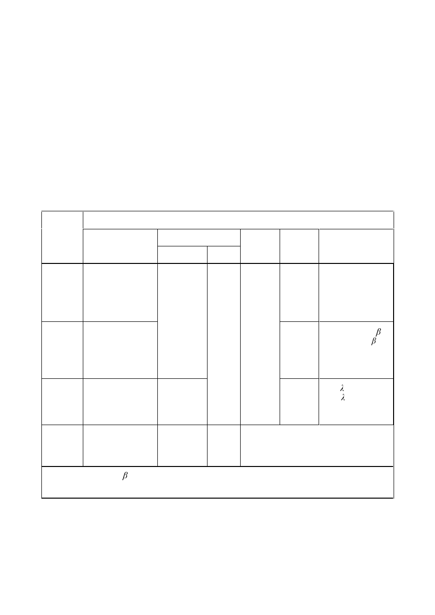
SU(1(
:HOGHGMRLQWVEHWZHHQ&+6RU5+6EUDFHPHPEHUVDQG5+6FKRUGPHPEHUV
*HQHUDO
(1)
Provided that the geometry of the joints is within the range of validity given in Table 7.8, the design
resistances of welded joints between hollow section brace members and rectangular or square hollow
section chord members may be determined using 7.5.2 and 7.5.3.
(2)
For joints within the range of validity given in Table 7.8, only the design criteria covered in the
appropriate table need be considered. The design resistance of a connection should be taken as the
minimum value for all applicable criteria.
(3)
For joints outside the range of validity given in Table 7.8, all the criteria given in 7.2.2 should be
considered. In addition, the secondary moments in the joints caused by their rotational stiffness should
be taken into account.
7DEOH5DQJHRIYDOLGLW\IRUZHOGHGMRLQWVEHWZHHQ&+6RU5+6EUDFH
PHPEHUVDQG5+6FKRUGPHPEHUV
Joint parameters [
L= 1 or 2, M= overlapped brace ]
E
i
/
W
i
and
K
i
/
W
i
or
G
i
/
W
i
Type of
joint
E
i
/
E
0
or
G
i
/
E
0
Compression
Tension
K
0
/
E
0
and
K
i
/
E
i
E
0
/
W
0
and
K
0
/
W
0
Gap or overlap
E
i
/
E
j
T, Y or X
E
i
/
E
0
and
Class 2
–
K gap
N gap
E
i
/
E
0
and
01
E
0
/
W
0
E
i
/
W
i
and
K
i
/
W
i
and
Class 2
and
Class 2
J
/
E
0
í )
but
í )
1)
and as a minimum
J W
1
+
W
2
K overlap
N overlap
E
i
/
E
0
Class 1
E
i
/
W
i
and
K
i
/
W
i
but
Class 2
ov
but
ov
2)
and
E
i
/
E
j
Circular
brace
member
G
i
/
E
0
but
Class 1
G
i
/
W
i
As above but with
G
i
replacing
E
i
and
G
j
replacing
E
j
.
1)
If
J
/
E
0
> 1,5(1
í ) and J
/
E
0
>
W
1
+
W
2
treat the joint as two separate T or Y joints.
2)
The overlap may be increased to enable the toe of the overlapped brace to be welded to the chord.

SU(1(
8QLSODQDUMRLQWV
8QUHLQIRUFHGMRLQWV
(1)
In brace member connections subject only to axial forces, the design internal axial force
1
i,Ed
should
not exceed the design axial resistance of the welded joint
1
i,Rd
, determined from 7.5.2.1(2) or
7.5.2.1(4) as appropriate.
(2)
For welded joints between square or circular hollow section brace members and square hollow section
chord members only, where the geometry of the joints is within the range of validity given in Table
7.8 and also satisfies the additional conditions given in Table 7.9, the design axial resistances may be
determined from the expressions given in Table 7.10.
(3)
For joints within the range of validity of Table 7.9, the only design criteria that need be considered are
chord face failure and brace failure with reduced effective width. The design axial resistance should be
taken as the minimum value for these two criteria.
127(The design axial resistances for joints of hollow section brace members to square hollow
section chords given in Table 7.10 have been simplified by omitting design criteria that are never
critical within the range of validity of Table 7.9.
(4)
The design axial resistances of any unreinforced welded joint between CHS or RHS brace members
and RHS chords, within the range of validity of Table 7.8, may be determined using the expressions
given in Table 7.11, Table 7.12 or Table 7.13 as appropriate. For reinforced joints see 7.5.2.2.
7DEOH$GGLWLRQDOFRQGLWLRQVIRUWKHXVHRI7DEOH
Type of brace
Type of joint
Joint parameters
T, Y or X
E
i
/
E
0
E
0
/
W
0
Square hollow section
K gap or N gap
0,6
1
2
1
2
E
E
E +
E
0
/
W
0
T, Y or X
E
0
/
W
0
Circular hollow section
K gap or N gap
0,6
1
2
1
2
G
G
G +
E
0
/
W
0
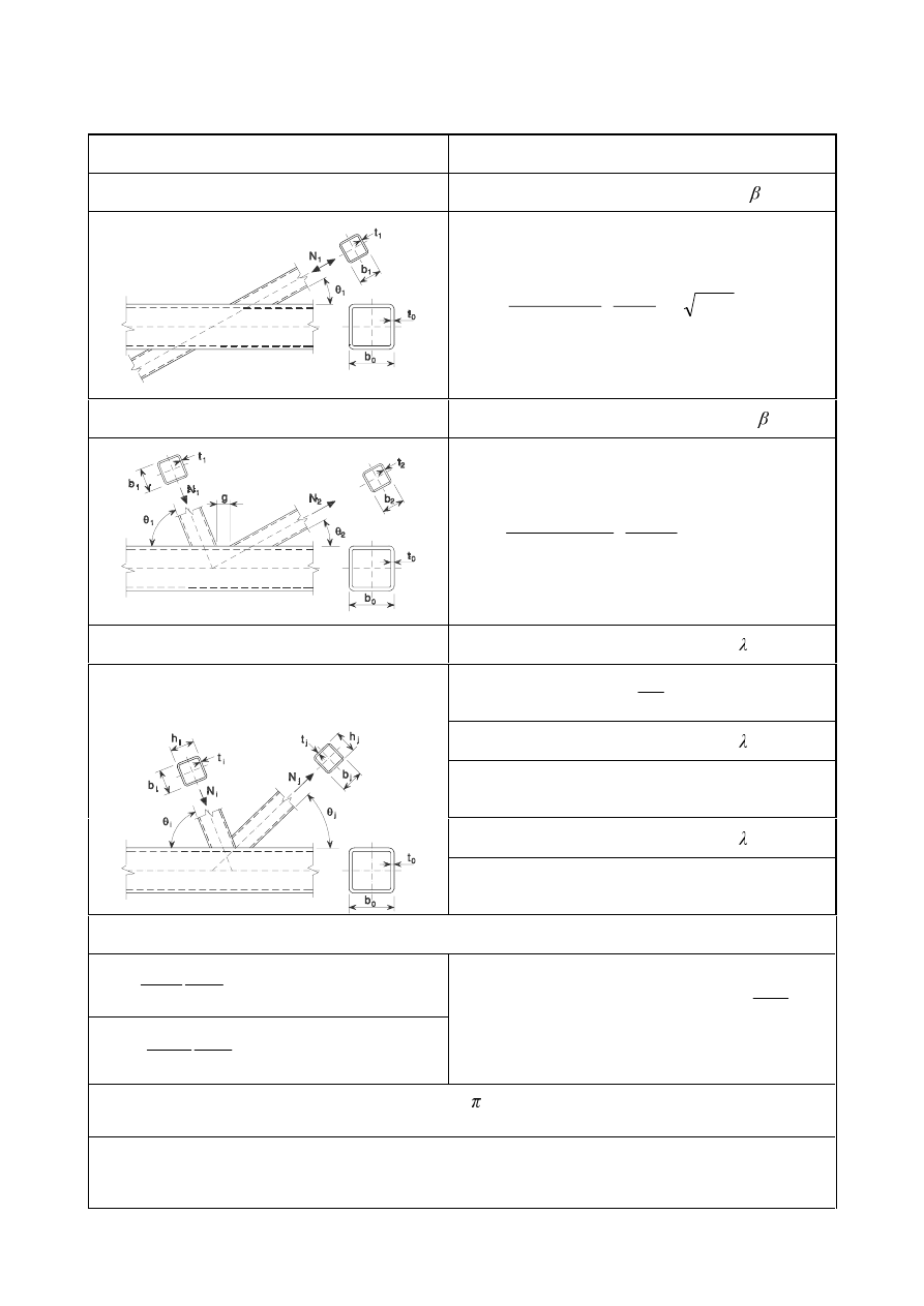
SU(1(
7DEOH'HVLJQD[LDOUHVLVWDQFHVRIZHOGHGMRLQWVEHWZHHQVTXDUHRUFLUFXODU
KROORZVHFWLRQ
Type of joint
Design resistance [
L = 1 or 2, M = overlapped brace]
T, Y and X joints
Chord face failure
1
1,Rd
=
(
)
5
1
1
2
0
0
/
1
4
sin
2
sin
1
0
\
Q
W
I
N
γ
β
θ
β
θ
β
−
+
−
K and N gap joints
Chord face failure
1
i,Rd
=
5
0
2
1
2
0
0
5
,
0
/
2
sin
9
,
8
0
L
\
Q
E
E
E
W
I
N
γ
θ
γ
+
K and N overlap joints *
)
Brace failure
25%
ov
< 50%
1
i,Rd
=
(
)
5
,
/
4
2
50
0
L
L
RY
RY
H
HII
L
\L
W
K
E
E
W
I
γ
λ
−
+
+
Brace failure
50%
ov
< 80%
1
i,Rd
=
[
]
5
,
/
4
2
0
L
L
RY
H
HII
L
\L
W
K
E
E
W
I
γ
−
+
+
Brace failure
ov
Member i or member j may be either tension or
compression but one shall be tension and the other
compression.
1
i,Rd
=
[
]
5
,
/
4
2
0
L
L
RY
H
L
L
\L
W
K
E
E
W
I
γ
−
+
+
Parameters
E
eff
,
E
e,ov
and
N
n
E
eff
=
L
L
\L
\
E
W
I
W
I
W
E
0
0
0
0
/
10
but
E
eff
E
i
E
e,ov
=
L
L
ML
M
\M
M
M
E
W
I
W
I
W
E /
10
but
E
e,ov
E
i
For
Q > 0 (compression):
N
n
=
β
Q
4
,
0
3
,
1
−
but
N
n
For
Q WHQVLRQ
N
n
= 1,0
For circular braces, multiply the above resistances by /4, replace
E
1
and
K
1
by
G
1
and replace
E
2
and
K
2
by
G
2
.
*
)
Only the overlapping brace member
Lneed be checked. The brace member efficiency (i.e. the design
resistance of the joint divided by the design plastic resistance of the brace member) of the
overlapped brace member
M should be taken as equal to that of the overlapping brace member.
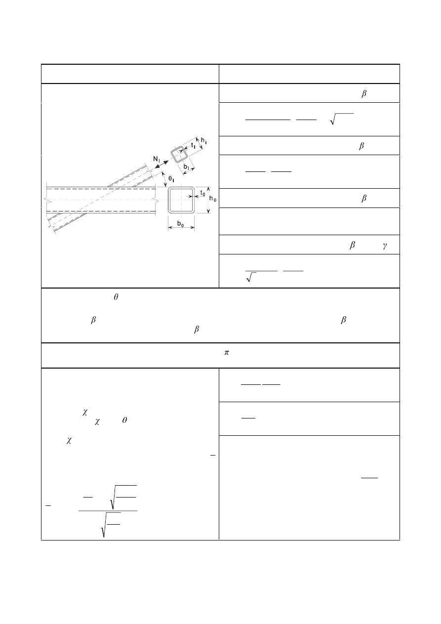
SU(1(
7DEOH'HVLJQD[LDOUHVLVWDQFHVRIZHOGHG7;DQG<MRLQWVEHWZHHQ5+6RU
&+6EUDFHVDQG5+6FKRUGV
Type of joint
Design resistance [
L = 1]
Chord face failure
1
i,Rd
=
5
1
1
2
0
0
/
1
4
sin
2
sin
)
1
(
0
\
Q
W
I
N
γ
β
θ
η
θ
β
−
+
−
Chord side wall buckling
1)
= 1,0
2)
1
i,Rd
=
5
0
1
0
/
10
sin
2
sin
0
L
L
E
W
K
W
I
γ
θ
θ
+
Brace failure
1
i,Rd
=
5
/
)
2
4
2
(
0
HII
L
L
L
\L
E
W
K
W
I
γ
+
−
Punching shear
0,85
- 1/ )
1
i,Rd
=
5
,
1
1
0
0
/
2
sin
2
sin
3
0
S
H
L
\
E
K
W
I
γ
θ
θ
+
1)
For X joints with < 90° use the smaller of this value and the design shear resistance of the chord side
walls given for K and N gap joints in Table 7.12.
2)
For 0,85
XVHOLQHDULQWHUSRODWLRQEHWZHHQWKHYDOXHIRU chord face failure at = 0,85 and the
governing value for chord side wall failure at = 1,0 (side wall buckling or chord shear).
For circular braces, multiply the above resistances by /4, replace
E
1
and
K
1
by
G
1
and replace
E
2
and
K
2
by
G
2
.
E
eff
=
L
L
\L
\
E
W
I
W
I
W
E
0
0
0
0
/
10
but
E
eff
E
i
E
e,p
=
L
E
W
E
0
0
10
but
E
e.p
E
i
For tension:
I
b
=
I
y0
For compression:
I
b
=
I
y0
(T
and
Y
joints)
I
b
= 0,8
I
y0
sin
i
(X joints)
where is the reduction factor for flexural buckling
obtained from EN 1993-1-1 using the relevant
buckling curve and a normalized slenderness
λ
determined from:
λ
=
0
0
0
sin
1
2
46
,
3
\
L
I
(
W
K
π
θ
−
For
Q > 0 (compression):
N
n
=
β
Q
4
,
0
3
,
1
−
but
N
n
,0
For
Q WHQVLRQ
N
n
= 1,0
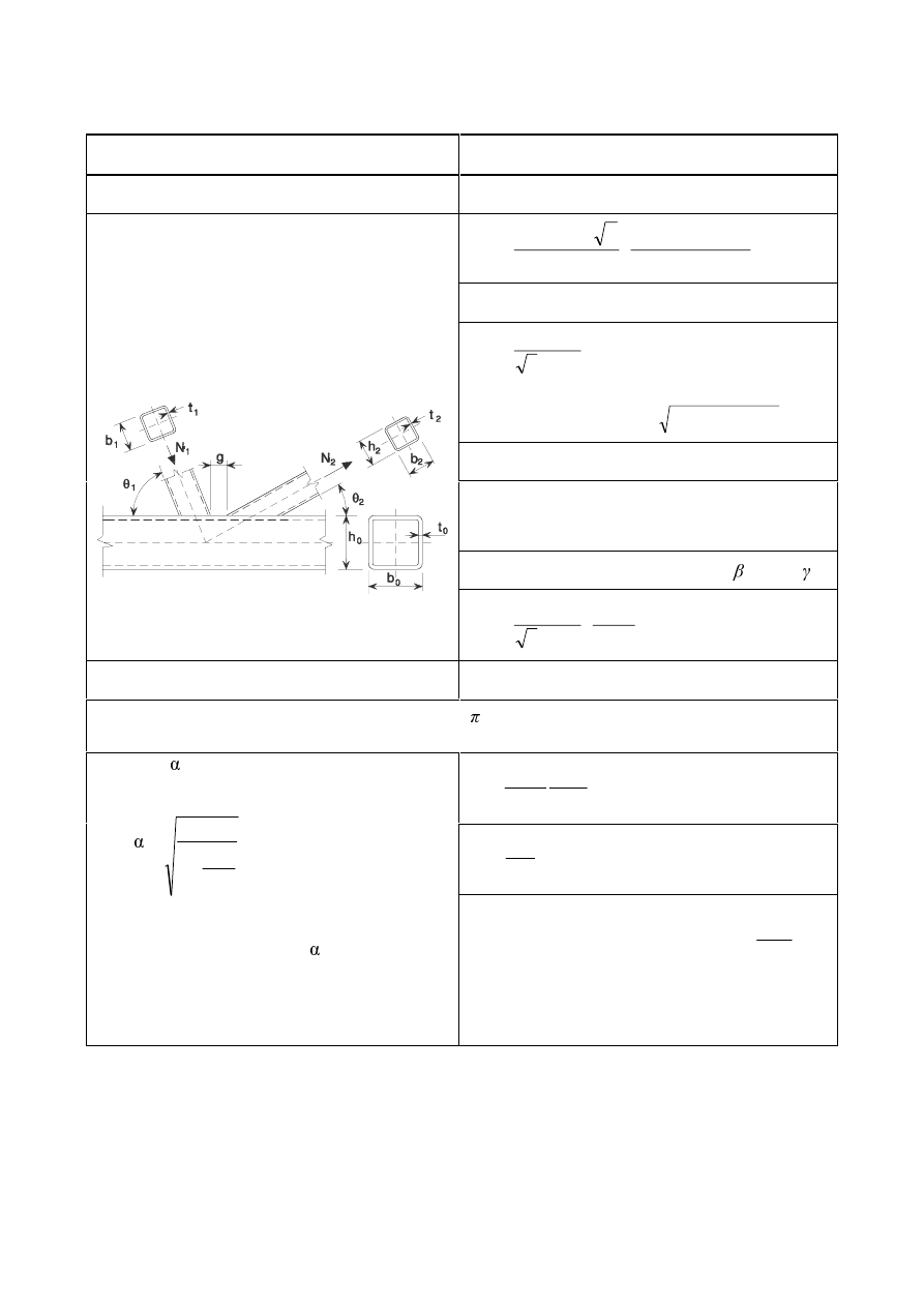
SU(1(
7DEOH'HVLJQD[LDOUHVLVWDQFHVRIZHOGHG.DQG1MRLQWVEHWZHHQ5+6RU
&+6EUDFHVDQG5+6FKRUGV
Type of joint
Design resistance [
L = 1 or 2]
K and N gap joints
Chord face failure
1
i,Rd
=
5
0
2
1
2
1
2
0
0
/
4
sin
9
,
8
0
L
\
Q
E
K
K
E
E
W
I
N
γ
θ
γ
+
+
+
Chord shear
1
i,Rd
=
5
0
/
sin
3
0
L
Y
\
$
I
γ
θ
1
0,Rd
=
(
)
(
)
5
2
,
0
0
0
/
/
1
0
5G
SO
6G
\
Y
\
Y
9
9
I
$
I
$
$
γ
−
+
−
Brace failure
1
i,Rd
=
(
)
5
/
4
2
0
HII
L
L
L
L
\L
E
E
W
K
W
I
γ
+
+
−
Punching shear
- 1/ )
1
i,Rd
=
5
,
0
0
/
sin
2
sin
3
0
S
H
L
L
L
L
\
E
E
K
W
I
γ
θ
θ
+
+
K and N overlap joints
As in Table 7.10.
For circular braces, multiply the above resistances by /4, replace
E
1
and
K
1
by
G
1
and replace
E
2
and
K
2
by
G
2
.
E
eff
=
L
L
\L
\
E
W
I
W
I
W
E
0
0
0
0
/
10
but
E
eff
E
i
E
e,p
=
L
E
W
E
0
0
10
but
E
e.p
E
i
$
v
= (2
K
0
E
0
)
W
0
For a square or rectangular brace member:
=
2
0
2
3
4
1
1
W
J
+
where
J is the gap, see Figure 1.3(a).
For a circular brace member:
For
Q > 0 (compression):
N
n
=
β
Q
4
,
0
3
,
1
−
but
N
n
For
Q WHQVLRQ
N
n
= 1,0
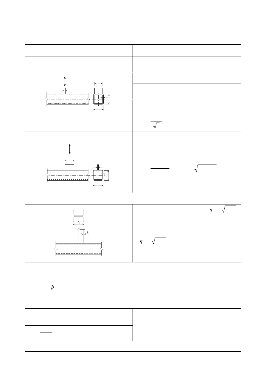
SU(1(
7DEOH'HVLJQUHVLVWDQFHVRIZHOGHGMRLQWVFRQQHFWLQJJXVVHWSODWHVRU,RU
+VHFWLRQVWR5+6PHPEHUV
Transverse plate
Brace failure [
L = 1]
1
1,Rd
=
5
1
1
/
0
HII
\
E
W
I
γ
*
)
Chord side wall crushing
when
E
1
E
0
íW
0
1
1,Rd
=
5
0
1
0
0
/
)
10
2
(
0
\
W
W
W
I
γ
+
Punching shear
when
E
1
E
0
íW
0
0
t
i
b
i
t
b
0
h
1
N
0
1
1,Rd
=
(
)
5
,
1
0
0
/
2
2
3
0
S
H
\
E
W
W
I
γ
+
Longitudinal plate
Chord face failure
0
t
0
h
b
0
t
i
i
h
1
N
W
1
/
E
0
1
1,Rd
=
(
)
5
0
1
0
1
0
1
2
0
0
/
/
1
4
/
2
/
1
0
\
P
E
W
E
K
E
W
W
I
N
γ
−
+
−
I or H section
As a conservative approximation, if
β
−
1
,
1
1,Rd
for an I or H section may be assumed to be
equal to the design resistance of two transverse
plates of similar dimensions to the flanges of the I
or H section, determined as specified above.
If < 2
β
−
1
, a linear interpolation between one
and two plates should be made.
0
ip,1,Rd
=
1
1,Rd
(
K
1
íW
1
)
Range of validity
In addition to the limits given in Table 7.8:
0,5
E
0
/
W
0
Parameters
E
eff
,
E
e,p
and
N
m
E
eff
=
1
1
1
0
0
0
0
/
10
E
W
I
W
I
W
E
\
\
but
E
eff
E
i
E
e,p
=
1
0
0
/
10 E
W
E
but
E
e.p
E
i
For
Q > 0 (compression):
N
m
=
)
1
(
3
,
1
Q
−
but
N
m
For
Q WHQVLRQ
N
m
= 1,0
*
)
Fillet welded connections should be designed in accordance with 4.10.

SU(1(
(5)
Brace member connections subjected to combined bending and axial force should satisfy the following
requirement:
5G
L
RS
(G
L
RS
5G
L
LS
(G
L
LS
5G
L
(G
L
0
0
0
0
1
1
,
,
,
,
,
,
,
,
,
,
+
+
...
(7.4)
where:
0
ip,i,Rd
is the design in-plane moment resistance
0
ip,i,Ed
is the design in-plane internal moment
0
op,i,Rd
is the design out-of-plane moment resistance
0
op,i,Ed
is the design out-of-plane internal moment
(6)
The design internal moment
0
i,Ed
may be taken as the value at the point where the centreline of the
brace member meets the face of the chord member.
(7) For unreinforced joints, the design in-plane moment resistance and design out-of-plane moment
resistance
0
i,Rd
should be obtained from Table 7.13 or Table 7.14 as appropriate. For reinforced
joints see 7.5.2.2.
(8) The special types of welded joints indicated in Table 7.15 and Table 7.16 should satisfy the
appropriate design criteria specified for each type in that table.
5HLQIRUFHGMRLQWV
(1)
Various types of joint reinforcement may be used. The appropriate type depends upon the failure mode
that, in the absence of reinforcement, governs the design resistance of the joint.
(2)
Flange reinforcing plates may be used to increase the resistance of the joint to chord face failure,
punching shear failure or brace failure with reduced effective width.
(3)
A pair of side plates may be used to reinforce a joint against chord side wall failure or chord shear
failure.
(4)
In order to avoid partial overlapping of brace members in a K or N joint, the brace members may be
welded to a vertical stiffener.
(5)
Any combinations of these types of joint reinforcement may also be used.
(6)
The grade of steel used for the reinforcement should not be lower than that of the chord member.
(7)
The design resistances of reinforced joints should be determined using Table 7.17 and Table 7.18.
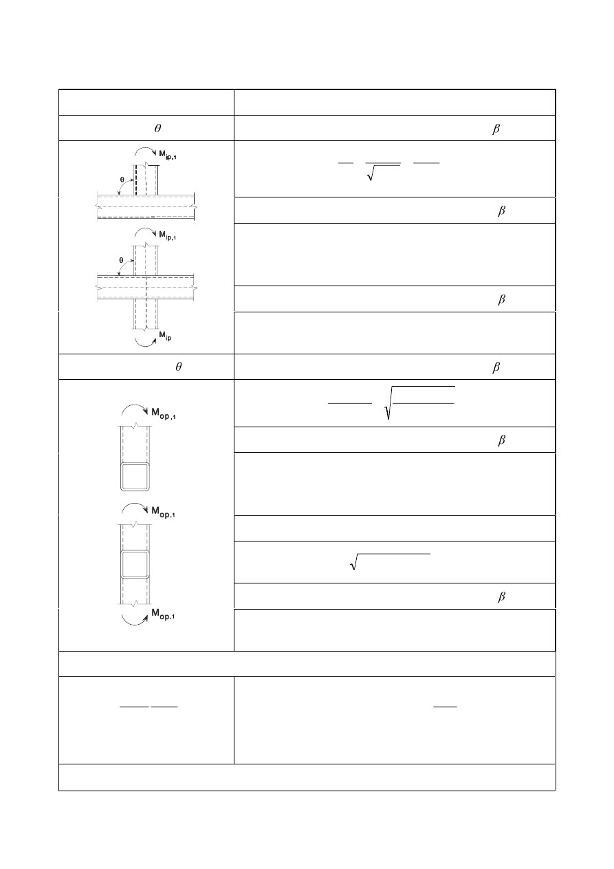
SU(1(
7DEOH'HVLJQUHVLVWDQFHPRPHQWVRIZHOGHGMRLQWVEHWZHHQ5+6EUDFH
PHPEHUVDQG5+6FKRUGV
T and X joints
Design resistance
In-plane moments ( = 90°)
Chord face failure
0
ip,1,Rd
=
5
1
2
0
0
/
1
1
2
2
1
0
\
Q
K
W
I
N
γ
β
η
β
η
−
+
−
+
Chord side wall crushing
0,85
0
ip,1,Rd
=
(
)
5
2
0
1
0
/
5
5
,
0
0
\N
W
K
W
I
γ
+
I
yk
=
I
y0
for T joints
I
yk
= 0,8
I
y0
for X joints
Brace failure
0,85
0
ip,1,Rd
=
(
)
(
)
5
1
1
1
1
1
(,
1
/
/
1
0
HII
S
\
W
K
E
E
E
:
I
γ
−
−
Out-of-plane moments ( = 90°)
Chord face failure
0
op,1,Rd
=
(
)
(
)
5
1
0
1
2
0
0
/
1
)
1
(
2
1
2
1
0
\
Q
E
E
K
W
I
N
γ
β
β
β
β
−
+
+
−
+
Chord side wall crushing
0,85
0
op,1,Rd
=
(
)
5
0
1
0
0
0
/
5
)
(
0
\N
W
K
W
E
W
I
γ
+
−
I
yk
=
I
y0
for T joints
I
yk
= 0,8
I
y0
for X joints
Chord distortional failure (T joints only) *)
0
op,1,Rd
=
(
)
(
)
5
0
0
0
0
0
0
1
0
0
/
2
0
\
K
E
W
K
E
W
K
W
I
γ
+
+
Brace failure
0,85
0
op,1,Rd
=
(
)
(
)
5
1
2
1
2
1
1
(,
1
/
/
1
5
,
0
0
HII
S
\
W
E
E
E
:
I
γ
−
−
Parameters
E
eff
and
N
n
E
eff
=
1
1
1
0
0
0
0
/
10
E
W
I
W
I
W
E
\
\
but
E
eff
E
1
For
Q > 0 (compression):
N
n
=
β
Q
4
,
0
3
,
1
−
but
N
n
For
Q WHQVLRQ
N
n
= 1,0
*)
This criterion does not apply where chord distortional failure is prevented by other means.
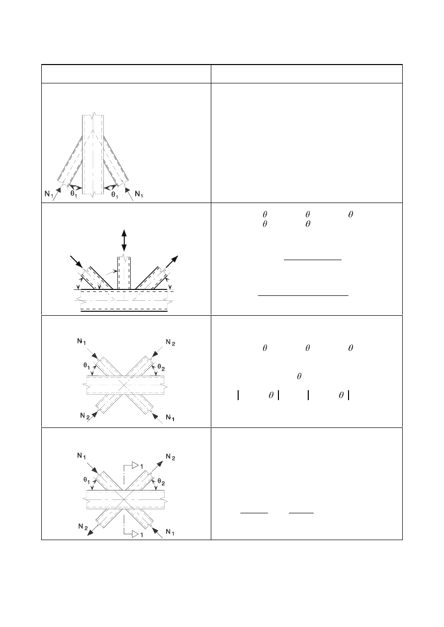
SU(1(
7DEOH'HVLJQFULWHULDIRUVSHFLDOW\SHVRIZHOGHGMRLQWVEHWZHHQ5+6EUDFH
PHPEHUVDQG5+6FKRUGV
Type of joint
Design criteria
The members may be in either tension or
compression and shall act as in the same
direction for both members.
1
1,Ed
1
1,Rd
where
1
1,Rd
is the value of
1
1,Rd
for an X joint from
Table 7.11.
The member 1 is always in compression and
member 2 is always in tension.
N
3
N
N
1
2
3
1
2
θ
θ
θ
1
1,Ed
sin
1
+
1
3,Ed
sin
3
1
1,Rd
sin
1
1
2,Ed
sin
2
1
1,Rd
sin
1
where
1
1,Rd
is the value of
1
1,Rd
for a K joint from
Table 7.12, but with
0
2
1
2
1
4
E
K
K
E
E
+
+
+
replaced by:
0
3
2
1
3
2
1
6
E
K
K
K
E
E
E
+
+
+
+
+
All bracing members shall be either compression
or tension.
1
1,Ed
sin
1
+
1
2,Ed
sin
2
1
x,Rd
sin
x
where
1
x,Rd
is the value of
1
x,Rd
for an X joint from
Table 7.11, and
1
x,Rd
sin
x
is the larger of:
1
1,Rd
sin
1
DQG 1
2,Rd
sin
2
Member 1 is always in compression and
member 2 is always in tension.
1
i,Ed
1
i,Rd
where
1
i,Rd
is the value of
1
i,Rd
for a K joint from
Table 7.12, provided that, in a gap-type joint, at section
1-1 the chord satisfies:
2
(,
,
0
,
0
2
(,
,
0
,
0
+
5G
S
(G
5G
S
(G
9
9
1
1
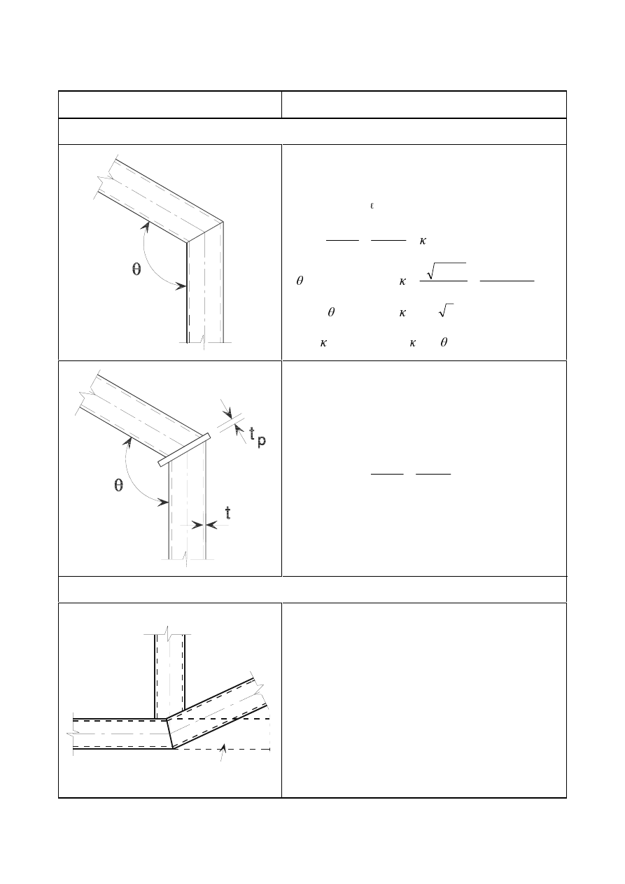
SU(1(
7DEOH'HVLJQFULWHULDIRUZHOGHGNQHHMRLQWVDQGFUDQNHGFKRUGMRLQWVLQ
5+6PHPEHUV
Type of joint
Criteria
Welded knee joints
The cross-section should be Class 1 for pure bending, see
EN 1993-1-1.
1
Ed
1
p
5G
and
5G
S
(G
5G
S
(G
0
0
1
1
(,
(,
+
If
=
[
]
0
0
8
,
0
0
0
0
0
/
2
1
1
/
/
3
K
E
W
E
K
E
+
+
If 90° <
=
(
)
(
)
90
1
)
2
/
cos(
2
1
κ
θ
−
−
where
90
is the value of for = 90°.
W
p
W and PP
5G
S
(G
5G
S
(G
0
0
1
1
(,
(,
+
Cranked-chord
i
j
Imaginary extension of chord
1
i,Ed
1
i,Rd
where
1
i,Rd
is the value of
1
i,Rd
for a K or N overlap joint
from Table 7.12.
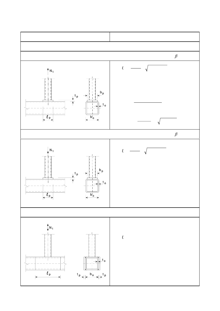
SU(1(
7DEOH'HVLJQUHVLVWDQFHVRIUHLQIRUFHGZHOGHG7<DQG;MRLQWVEHWZHHQ
5+6RU&+6EUDFHPHPEHUVDQG5+6FKRUGV
Type of joint
Design resistance [
L = 1 ]
Reinforced with flange plates to avoid chord face failure, brace failure or punching shear.
Tension loading
p
p
(
)
L
S
S
L
L
E
E
E
K
−
+
θ
sin
L
L
K
θ
sin
/
5
,
1
and
E
p
E
0
íW
0
1
i,Rd
=
(
)
[
E
E
W
I
L
S
L
S
\S
θ
sin
/
1
2
−
5
/
/
1
4
sin
/
2
0
S
L
L
S
L
E
E
E
K
[
γ
θ
−
+
Compression loading
p
p
(
)
L
S
S
L
L
E
E
E
K
−
+
θ
sin
L
L
K
θ
sin
/
5
,
1
and
E
p
E
0
íW
0
Take
1
i,Rd
as the value of
1
i,Rd
for a T, X or Y
joint from Table 7.11, but with
N
n
= 1,0 and
W
0
replaced by
W
p
for chord face failure, brace failure
and punching shear only.
Reinforced with side plates to avoid chord side wall buckling or chord side wall shear.
p
L
L
K
θ
sin
/
5
,
1
Take
1
i,Rd
as the value of
1
i,Rd
for a T, X or Y
joint from Table 7.11, but with
W
0
replaced by (
W
0
+
W
p
) for chord side wall buckling failure and chord
side wall shear failure only.
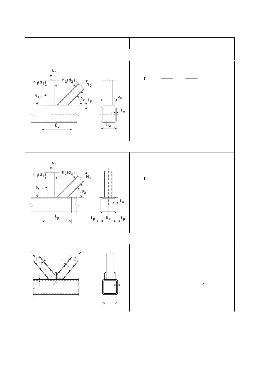
SU(1(
7DEOH'HVLJQUHVLVWDQFHVRIUHLQIRUFHGZHOGHG.DQG1MRLQWVEHWZHHQ5+6
RU&+6EUDFHPHPEHUVDQG5+6FKRUGV
Type of joint
Design resistance [
L = 1 or 2]
Reinforced with flange plates to avoid chord face failure, brace failure or punching shear.
p
+
+
2
2
1
1
sin
sin
5
,
1
θ
θ
K
J
K
E
p
E
0
í
W
0
W
p
W
1
and 2
W
2
Take
1
i,Rd
as the value of
1
i,Rd
for a K or N joint
from Table 7.12, but with
W
0
replaced by
W
p
for
chord face failure, brace failure and punching shear
only.
Reinforced with a pair of side plates to avoid chord shear failure.
p
+
+
2
2
1
1
sin
sin
5
,
1
θ
θ
K
J
K
Take N
i,Rd
as the value of
1
i,Rd
for a K or N joint
from Table 7.12, but with
W
0
replaced by (
W
0
+
W
p
)
for chord shear failure only.
Reinforced by a division plate between the brace members because of insufficient overlap.
t
o
b
o
t
o
t
t
1
2
N
2
N
1
W
p
W
1
and 2
W
2
Take
1
i,Rd
as the value of
1
i,Rd
for a K or N
overlap joint from Table 7.12 with
ov
< 80%, but
with
E
j
,
W
j
and
I
yj
replaced by
E
p
,
W
p
and
I
yp
in the
expression for
E
e,ov
given in Table 7.10.
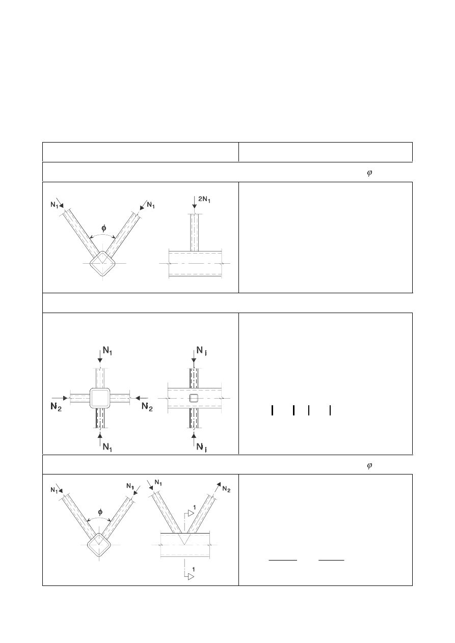
SU(1(
0XOWLSODQDUMRLQWV
(1)
In each relevant plane of a multiplanar joint, the design criteria given in 7.5.2 should be satisfied using
the reduced design resistances obtained from 7.5.3(2).
(2)
The design resistances for each relevant plane of a multiplanar joint should be determined by applying
the appropriate reduction factor
given in Table 7.19 to the resistance of the corresponding uniplanar
joint calculated according to 7.5.2 with the appropriate chord load in the multiplanar situation.
7DEOH5HGXFWLRQIDFWRUVIRUPXOWLSODQDUMRLQWV
Type of joint
Reduction factor
TT joint
60°
Member 1 may be either tension or compression.
= 0,9
XX joint
Members 1 and 2 can be either in compression or
tension.
1
2,Ed
/
1
1,Ed
is negative if one member is in
tension and one in compression.
=
(
)
(G
(G
1
1
,
1
,
2
/
33
,
0
1
9
,
0
+
taking account of the sign of
1
1,Ed
and
1
2,Ed
where
1
2,Ed
1
1,Ed
KK joint
60°
µ = 0,9
provided that, in a gap-type joint, at section 1-1
the chord satisfies:
2
,
0
(,
,
0
2
,
0
(,
,
0
+
5G
S
(G
5G
S
(G
9
9
1
1
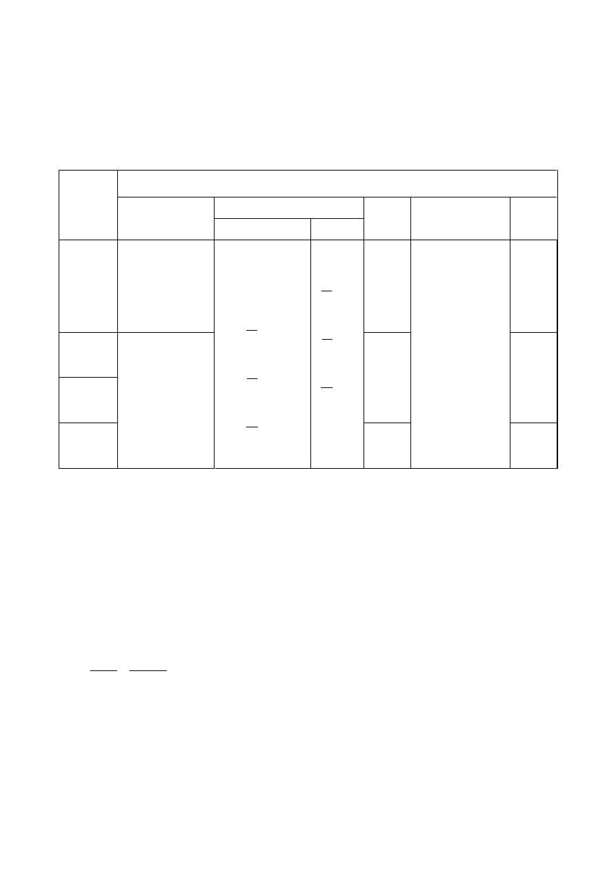
SU(1(
:HOGHGMRLQWVEHWZHHQ&+6RU5+6EUDFHPHPEHUVDQG,RU+VHFWLRQFKRUGV
(1)
Provided that the geometry of the joints is within the range of validity given in Table 7.20, the design
resistances of the joints should be determined using the expressions given in Table 7.21 or Table 7.22
as appropriate.
7DEOH5DQJHRIYDOLGLW\IRUZHOGHGMRLQWVEHWZHHQ&+6RU5+6EUDFH
PHPEHUVDQG,RU+VHFWLRQFKRUGPHPEHUV
Joint parameter [
L = 1 or 2, M= overlapped brace ]
E
i
/
W
i
and
K
i
/
W
i
or
G
i
/
W
i
Type of
joint
G
w
/
W
w
Compression
Tension
K
i
/
E
i
E
0
/
W
f
b
i
/b
j
X
Class 1
and
G
w
mm
but
–
T or Y
K gap
N gap
1,0
–
K overlap
N overlap
Class 2
and
G
w
mm
Class 1
and
L
L
W
K
L
L
W
E
L
L
W
G
L
L
W
K
L
L
W
E
L
L
W
G
but
Class 2
(2)
For joints within the range of validity given in Table 7.20, only the design criteria covered in the
appropriate table need be considered. The design resistance of a connection should be taken as the
minimum value for all applicable criteria.
(3)
For joints outside the range of validity given in Table 7.20, all the criteria given in 7.2.2 should be
considered. In addition, the secondary moments in the joints caused by their rotational stiffness should
be taken into account.
(4)
In brace member connections subjected only to axial forces, the design axial force
1
i,Ed
should not
exceed the design axial resistance of the welded joint
1
i,Rd
, determined from Table 7.21.
(5)
Brace member connections subject to combined bending and axial force should satisfy:
5G
L
LS
(G
L
LS
5G
L
(G
L
0
0
1
1
,
,
,
,
,
,
+
...
(7.5)
where:
0
ip,i,Rd
is the design in-plane moment resistance;
0
ip,i,Ed
is the design in-plane internal moment.
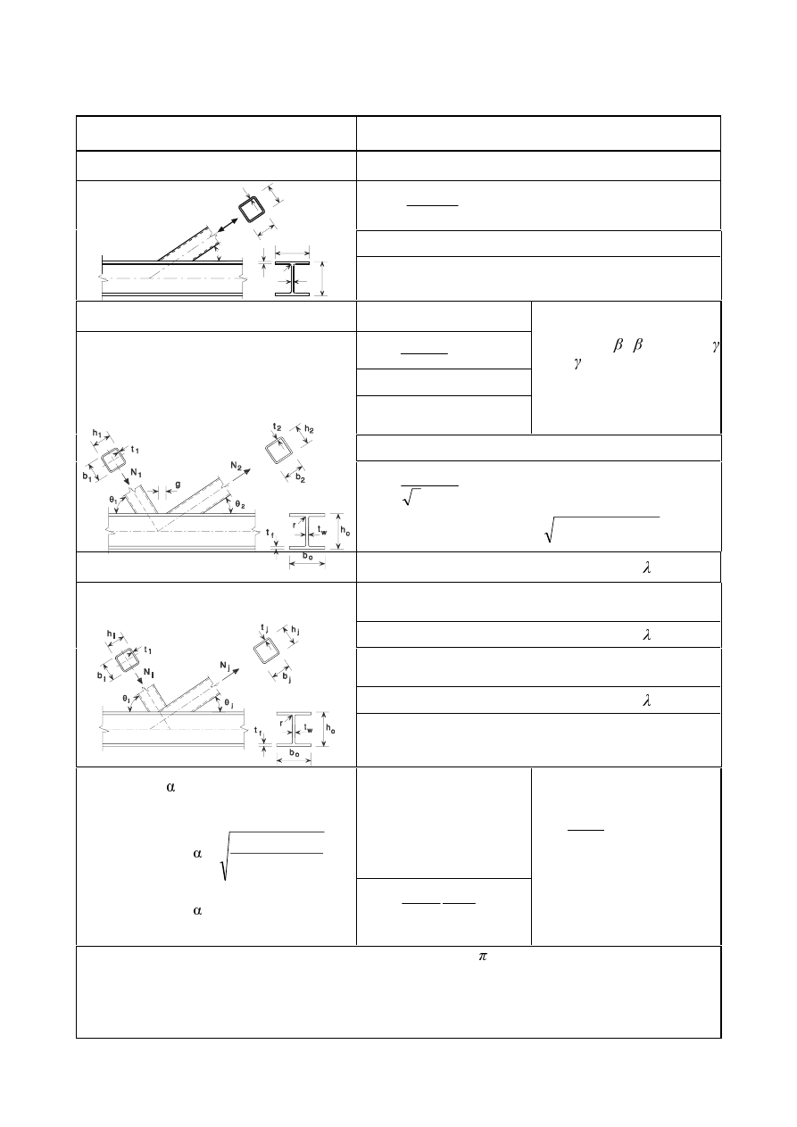
SU(1(
7DEOH'HVLJQUHVLVWDQFHVRIZHOGHGMRLQWVEHWZHHQ5+6RU&+6EUDFH
PHPEHUVDQG,RU+VHFWLRQFKRUGV
Type of joint
Design resistance [
L = 1 or 2, M= overlapped brace ]
T, Y and X joints
Chord web yielding
1
1,Rd
=
5
1
0
/
sin
0
Z
Z
\
E
W
I
γ
θ
Brace failure
1
b
o
t
w
o
h
t
f
N
1
b
1
h
1
1
t
r
θ
1
1,Rd
=
5
1
1
/
2
0
HII
\
S
W
I
γ
K and N gap joints
[
L = 1 or 2]
Chord web stability
1
i,Rd
=
5
0
/
0
Z
Z
\
E
W
I
γ
θ
Brace failure
1
i,Rd
=
5
/
2
0
HII
L
\L
S
W
I
γ
Brace failure need not be
checked if:
J/W
f
í í
where =
E
0
/2
W
f
and for CHS:
0,75
G
1
/
G
2
or for RHS:
0,75
E /E
Chord shear
1
i,Rd
=
5
0
/
sin
3
0
L
Y
\
$
I
γ
θ
1
0,Rd
=
(
)
(
)
5
2
,
1
0
0
0
/
/
1
0
5G
S
(G
\
Y
\
Y
9
9
I
$
I
$
$
γ
−
+
−
K and N overlap joints
*)
[
L = 1 or 2]
Brace failure
25%
ov
< 50%
1
i,Rd
=
(
)
5
,
/
50
/
)
2
(
0
RY
L
L
RY
H
HII
L
\L
W
K
E
S
W
I
γ
λ
−
+
+
Brace failure
50%
ov
< 80%
1
i,Rd
=
(
)
5
,
/
2
0
L
L
RY
H
HII
L
\L
W
K
E
S
W
I
γ
−
+
+
Brace failure
ov
Members i and j may be in either tension or
compression.
1
i,Rd
=
(
)
5
,
/
4
2
0
L
L
RY
H
L
L
\L
W
K
E
E
W
I
γ
−
+
+
S
eff
=
\L
\
I
Z
I
I
W
U
W
/
7
2
0
+
+
but
S
eff
E
i
+
K
i
-2
W
i
for T, Y, X joints and K and
N gap joints and
E
eff
E
i
+
K
i
-2
W
i
for K and N overlap joints.
$
v
=
$
0
íí ) E
0
W
f
+ (
W
w
+ 2
U) W
f
For RHS brace:
=
(
)
2
2
3
/
4
1
1
I
W
J
+
For CHS brace:
E
e,ov
=
L
L
\L
M
\M
M
M
E
W
I
W
I
W
E /
10
but
E
e,ov
E
i
E
w
=
(
)
U
W
K
I
L
L
+
+ 5
sin
θ
but
E
w
W
i
+ 10 (
W
f
+
U)
For CHS braces multiply the above resistances for brace failure by /4 and replace both b
1
and h
1
by d
1
and
both b
2
and h
2
by d
2
.
*)
Only the overlapping brace member
L need be checked. The efficiency (i.e. the design resistance of
the joint divided by the design plastic resistance of the brace member) of the overlapped brace
member
M should be taken as equal to that of the overlapping brace member.
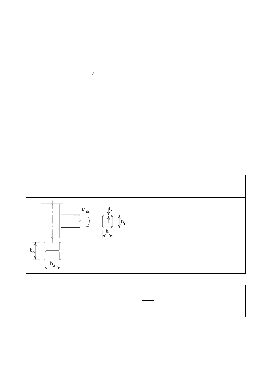
SU(1(
(6)
The design internal moment
0
i,Ed
may be taken as the value at the point where the centreline of the
brace member meets the face of the chord member.
(7)
The design in-plane moment resistance
0
ip,1,Rd
should be obtained from Table 7.22.
(8)
If stiffeners in the chord (see Figure 7.7) are used, then the design bracing failure resistance
1
i,Rd
for
T-, X-, Y-, K-gap and N-gap joints (Table 7.22) is determined as follows:
1
i,Rd
= 2
I
yi
W
i
(
E
eff
+
E
eff,s
) /
M5
...
(7.6)
where:
E
eff
=
W
w
+ 2
U + 7 W
f
I
y0
/
I
yi
but
E
i
+
K
i
- 2
W
i
E
eff,s
=
W
s
+ 2
D + 7 W
f
I
y0
/
I
yi
but
E
i
+
K
i
- 2
W
i
E
eff
+
E
eff,s
E
i
+
K
i
- 2
W
i
where:
D is stiffener weld throat thickness, ’2D’ becomes ’D’ if single sided fillet welds are used;
V refers to the stiffener.
(9)
The stiffeners should be at least as thick as the I-section web.
7DEOH'HVLJQPRPHQWUHVLVWDQFHVRIZHOGHGMRLQWVEHWZHHQUHFWDQJXODU
KROORZVHFWLRQEUDFHPHPEHUVDQG,RU+VHFWLRQFKRUGV
Type of joint
Design resistance [
L = 1 or 2, M = overlapped brace]
T and Y joints
Chord web yielding
0
ip,1,Rd
=
5
1
0
/
5
,
0
0
Z
Z
\
K
E
W
I
γ
Brace failure
0
ip,1,Rd
=
5
1
1
1
1
/
)
(
0
HII
\
W
K
E
W
I
γ
−
Parameters
E
eff
and
E
w
E
eff
=
1
0
/
7
2
\
\
I
Z
I
I
W
U
W
+
+
but
E
eff
E
i
E
w
=
( )
U
W
K
I
+
+ 5
sin
1
1
θ
but
E
w
(
)
U
W
W
I
+
+10
2
1
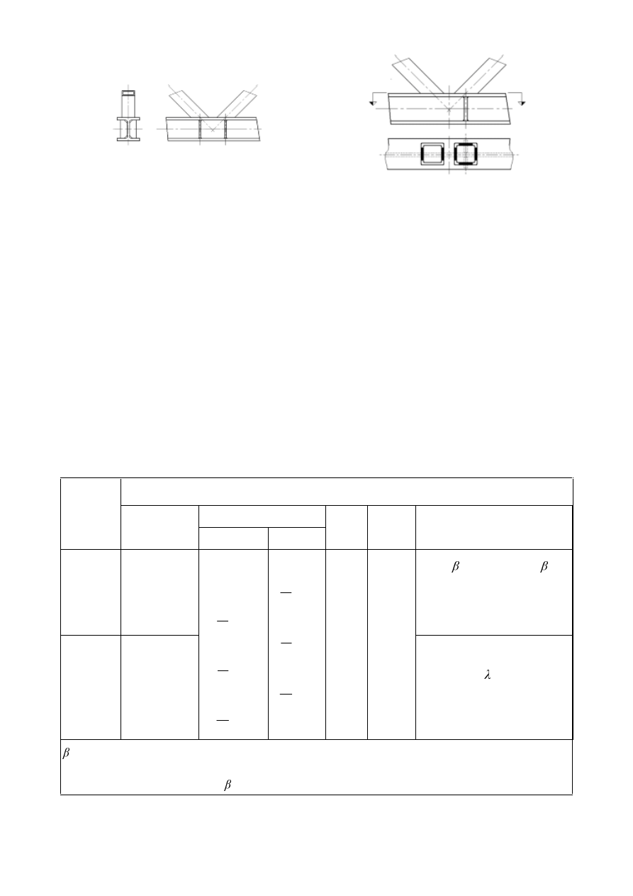
SU(1(
Bracing effective perimeter, without (left) and
with (right) stiffeners
)LJXUH6WLIIHQHUVIRU,VHFWLRQFKRUGV
:HOGHG MRLQWV EHWZHHQ &+6 RU 5+6 EUDFH PHPEHUV DQG FKDQQHO VHFWLRQ
FKRUGPHPEHUV
(1)
Provided that the geometry of the joints is within the range of validity given in Table 7.23, the design
resistances of welded joints between hollow section brace members and channel section chord
members may be determined using Table 7.24.
(2)
The secondary moments in the joints caused by their bending stiffness should be taken into account.
(3)
In a gap type joint, the design axial resistance of the chord cross-section
1
0,Rd
should be determined
allowing for the shear force transferred between the brace members by the chord, neglecting the
associated secondary moment. Verification should be made according to EN 1993-1-1.
7DEOH5DQJHRIYDOLGLW\IRUZHOGHGMRLQWVEHWZHHQ&+6RU5+6EUDFH
PHPEHUVDQGFKDQQHOVHFWLRQFKRUG
Joint parameter [
L = 1 or 2, M= overlapped brace ]
E
i
/
W
i
and
K
i
/
W
i
or
G
i
/
W
i
Type of
joint
E
i
/
E
0
Compression
Tension
K
i
/
E
i
E
0
/
W
0
Gap or overlap
b
i
/b
j
K gap
N gap
and
E
0
mm
0,5(1-
*
)
JE
0
*
-
*
)
1)
and
g
W
1
+ t
2
K overlap
N overlap
and
E
0
mm
Class 1
and
L
L
W
K
L
L
W
E
L
L
W
G
L
L
W
K
L
L
W
E
L
L
W
G
but
Class 2
25%
ov
< 100%
E
i
/
E
j
*
=
E
1
/b
0
*
E
0
*
=
E
0
- 2 (
W
w
+
U
0
)
1)
This condition only apply when
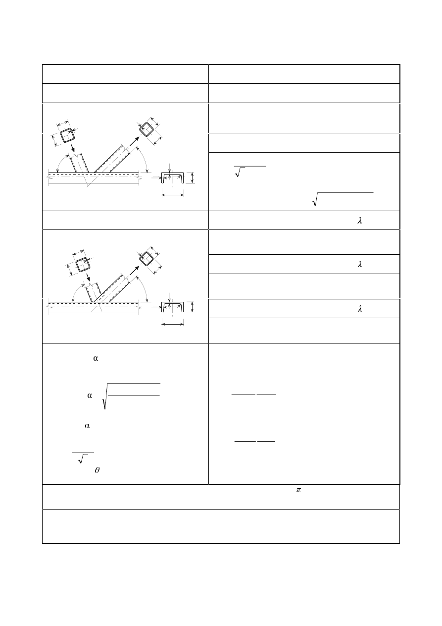
SU(1(
7DEOH'HVLJQUHVLVWDQFHRIZHOGHGMRLQWVEHWZHHQ5+6RU&+6EUDFH
PHPEHUVDQGFKDQQHOVHFWLRQFKRUGV
Type of joint
Design resistance [
L = 1 or 2, M = overlapped brace]
K and N gap joints
Brace failure
1
i,Rd
=
(
)
5
/
4
2
0
L
L
HII
L
L
\L
W
K
E
E
W
I
γ
−
+
+
Chord failure
t
t
r
b
h
w
0
0
0
0
N
b
j
j
h
t
j
j
j
θ
t
b
N
h
i
i
i
i
i
θ
1
i,Rd
=
5
0
/
sin
3
0
L
Y
\
$
I
γ
θ
1
0,Rd
=
(
)
(
)
5
2
,
0
0
0
/
/
1
0
5G
SO
(G
\
Y
\
Y
9
9
I
$
I
$
$
γ
−
+
−
K and N overlap joints *
)
Brace
failure 25%
ov
< 50%
1
i,Rd
=
(
)
(
)
5
,
/
50
/
4
2
0
RY
L
L
RY
H
HII
L
\L
W
K
E
E
W
I
γ
λ
−
+
+
Brace failure
50%
ov
< 80%
1
i,Rd
=
(
)
5
,
/
4
2
0
L
L
RY
H
HII
L
\L
W
K
E
E
W
I
γ
−
+
+
Brace failure
ov
t
t
b
h
w
0
0
0
N
b
j
j
h
t
j
j
j
θ
t
b
N
h
i
i
i
i
i
θ
r
0
1
i,Rd
=
(
)
5
,
/
4
2
0
L
L
RY
H
L
L
\L
W
K
E
E
W
I
γ
−
+
+
$
v
=
$
0
íí ) E
0
*
W
0
E
0
*
=
E
0
- 2 (
W
w
+
U
0
)
For RHS:
=
(
)
2
2
3
/
4
1
1
I
W
J
+
)RU&+6
9
pl,Rd
=
5
0
/
3
0
Y
\
$
I
γ
9
Ed
= (
1
i,Ed
sin
i
)
max
E
eff
=
L
L
\L
\
E
W
I
W
I
W
E
0
0
0
*
0
/
10
but
E
eff
E
i
E
e,ov
=
L
L
\L
M
\M
M
M
E
W
I
W
I
W
E /
10
but
E
e,ov
E
i
For CHS braces except the chord failure, multiply the above resistances by /4 and replace both
E
1
and
K
1
by
G
1
as well as
E
2
and
K
2
by
G
2
.
*
)
Only the overlapping brace member
L needs to be checked. The efficiency (i.e. the design resistance
of the joint divided by the design plastic resistance of the brace member) of the overlapped brace
member
M should be taken as equal to that of the overlapping brace member.
Wyszukiwarka
Podobne podstrony:
Eurocode 3 Part 1,9 PrEN 1993 1 9 2003
Eurocode 3 Part 1,8 prEN 1993 1 8 2003
Eurocode 3 Part 1,9 PrEN 1993 1 9 2003
Eurocode 1 Part 1,3 prEN 1991 1 3 2003
Eurocode 3 Part 2 (prEN 1993 2 March 2004)
Eurocode 8 Part 4 prEN 1998 4 2003 (12 2003)
Eurocode 1 Part 1,5 prEN 1991 1 5 2003
Eurocode 3 Part 1,5 prEN 1993 1 5 2004 (Juin 2004)
Eurocode 3 Part 3 prEN 1993 3 2001
Eurocode 1 Part 1,7 prEN 1991 1 7 2003
Eurocode 3 Part 5 prEN 1993 5 (2004 Jul)
Eurocode 3 Part 5 prEN 1993 5 (2004 Jul)
Eurocode 3 Part 3 prEN 1993 3 2001
Eurocode 8 Part 1 prEN 1998 1 (12 2003)
Eurocode 8 Part 5 prEn 1998 5 (12 2003)
Eurocode 8 Part 3 prEN 1998 3 (07 2003)
więcej podobnych podstron