
Revised Final PT Draft (pre Stage 49)
Page 1
Draft July 2003
prEN 1998-3:200X
EUROPEAN STANDARD
prEN 1998-3
NORME EUROPÉENNE
EUROPÄISCHE NORM
Doc CEN/TC250/SC8/N371
English version
Eurocode 8: Design of structures for earthquake resistance
Part 3: Strengthening and repair of buildings
DRAFT No 4
Revised Final Project Team Draft (pre Stage 49)
July 2003
CEN
European Committee for Standardization
Comité Européen de Normalisation
Europäisches Komitee für Normung
Central Secretariat: rue de Stassart 36, B1050 Brussels
CEN 2003 Copyright reserved to all CEN members
Ref.No: prEN 1998-3:200X

Revised Final PT Draft (pre Stage 49)
Page 2
Draft July 2003
prEN 1998-3:200X
Foreword...............................................................................................................................6
S
TATUS AND FIELD OF APPLICATION OF
E
UROCODES
.....................................................7
N
ATIONAL
S
TANDARDS IMPLEMENTING
E
UROCODES
....................................................8
L
INKS BETWEEN
E
UROCODES AND HARMONISED TECHNICAL SPECIFICATIONS
(EN
S
AND
ETA
S
)
FOR PRODUCTS
..............................................................................................8
NATIONAL ANNEX FOR EN 1998-3 ............................................................................9
1
GENERAL .................................................................................................................10
1.1 S
COPE
......................................................................................................................10
1.2 A
SSUMPTIONS
..........................................................................................................11
1.3 D
ISTINCTION BETWEEN PRINCIPLES AND APPLICATION RULES
............................11
1.4 D
EFINITIONS
............................................................................................................11
1.5 S
YMBOLS
.................................................................................................................11
1.6 S.I. U
NITS
.................................................................................................................11
2
PERFORMANCE REQUIREMENTS AND COMPLIANCE CRITERIA....12
2.1 F
UNDAMENTAL REQUIREMENTS
............................................................................12
2.2 C
OMPLIANCE CRITERIA
...........................................................................................13
2.2.1
General............................................................................................................13
2.2.2
Limit State of Near Collapse.........................................................................13
2.2.3
Limit State of Significant Damage ..............................................................13
2.2.4
Limit State of Damage Limitation ...............................................................14
3
INFORMATION FOR STRUCTURAL ASSESSMENT ...................................14
3.1 G
ENERAL INFORMATION AND HISTORY
.................................................................14
3.2 R
EQUIRED INPUT DATA
...........................................................................................14
3.3 K
NOWLEDGE LEVELS
..............................................................................................15
3.3.1
KL1: Limited knowledge................................................................................16
3.3.2
KL2: Normal knowledge ................................................................................17
3.3.3
KL3: Full knowledge ......................................................................................17
3.4 I
DENTIFICATION OF THE
K
NOWLEDGE
L
EVEL
......................................................18
3.4.1
Geometry.........................................................................................................18
3.4.2
Details .............................................................................................................19
3.4.3
Materials.........................................................................................................19
3.4.4
Definition of the levels of inspection and testing .......................................20
3.5 P
ARTIAL
S
AFETY
F
ACTORS
.....................................................................................20
4
ASSESSMENT ..........................................................................................................21
4.1 G
ENERAL
.................................................................................................................21
4.2 S
EISMIC ACTION AND SEISMIC LOAD COMBINATION
.............................................21
4.3 S
TRUCTURAL MODELLING
......................................................................................21
4.4 M
ETHODS OF ANALYSIS
..........................................................................................22
4.4.1
General............................................................................................................22
4.4.2
Lateral force analysis ....................................................................................22
4.4.3
Multi-modal response spectrum analysis ....................................................23
4.4.4
Nonlinear static analysis ..............................................................................23
4.4.5
Nonlinear time-history analysis ...................................................................24

Revised Final PT Draft (pre Stage 49)
Page 3
Draft July 2003
prEN 1998-3:200X
4.4.6
Combination of the components of the seismic action ..............................24
4.4.7
Additional measures for masonry infilled structures .................................24
4.4.8
Combination coefficients for variable actions ...........................................24
4.4.9
Importance categories and importance factors .........................................24
4.5 S
AFETY VERIFICATIONS
..........................................................................................24
4.5.1
Linear methods of analysis (static or dynamic)..........................................24
4.5.2
Nonlinear methods of analysis (static or dynamic)....................................25
5
DECISIONS FOR STRUCTURAL INTERVENTION ......................................26
5.1 C
RITERIA FOR A STRUCTURAL INTERVENTION
......................................................26
5.1.1
Technical criteria...........................................................................................26
5.1.2
Type of intervention.......................................................................................26
5.1.3
Non-structural elements ................................................................................27
5.1.4
Justification of the selected intervention type ............................................27
6
DESIGN OF STRUCTURAL INTERVENTION ................................................28
6.1 R
EDESIGN
P
ROCEDURE
..........................................................................................28
ANNEX A (INFORMATIVE) .........................................................................................29
A.1
SCOPE....................................................................................................................29
A.2
IDENTIFICATION OF GEOMETRY, DETAILS AND MATERIALS .....29
A.2.1 G
ENERAL
.............................................................................................................29
A.2.2 G
EOMETRY
..........................................................................................................29
A.2.3 D
ETAILS
...............................................................................................................29
A.2.4 M
ATERIALS
..........................................................................................................30
A.3
CAPACITY MODELS FOR ASSESSMENT ..................................................30
A.3.1 B
EAM
-
COLUMNS UNDER FLEXURE WITH AND WITHOUT AXIAL FORCE AND
WALLS
30
A.3.1.1
LS of near collapse (NC) ...........................................................................30
A.3.1.2
LS of severe damage (SD) .........................................................................33
A.3.1.3
LS of damage limitation (DL)...................................................................33
A.3.2 B
EAM
-
COLUMNS AND WALLS
:
SHEAR
................................................................33
A.3.2.1
LS of near collapse (NC) ...........................................................................33
A.3.2.2
LS of severe damage (SD) and of damage limitation (DL) ....................34
A.3.3 B
EAM
-
COLUMN JOINTS
.......................................................................................35
A.3.3.1
LS of near collapse (NC) ...........................................................................35
A.3.3.2
LS of severe damage (SD) and of damage limitation (DL) ....................35
A.4
CAPACITY MODELS FOR STRENGTHENING..........................................35
A.4.1 C
ONCRETE JACKETING
.......................................................................................35
A.4.1.1
Enhancement of strength and deformation capacities ..........................35
A.4.2 S
TEEL JACKETING
...............................................................................................36
A.4.2.1
Shear strength ............................................................................................36
A.4.2.2
Confinement action ...................................................................................36
A.4.2.3
Clamping of lap-splices .............................................................................37
A.4.3 FRP
PLATING AND WRAPPING
............................................................................37
A.4.3.1
Shear strength ............................................................................................38

Revised Final PT Draft (pre Stage 49)
Page 4
Draft July 2003
prEN 1998-3:200X
A.4.3.2
Confinement action ...................................................................................39
A.4.3.3
Clamping of lap-splices.............................................................................40
B.1
SCOPE....................................................................................................................41
B.2
IDENTIFICATION OF GEOMETRY, DETAILS AND MATERIALS .....41
B.2.1
G
ENERAL
.............................................................................................................41
B.2.2
G
EOMETRY
..........................................................................................................41
B.2.3
D
ETAILS
...............................................................................................................42
(1) The collected data should include the following items:..................................42
B.2.4
M
ATERIALS
..........................................................................................................42
B.3
REQUIREMENTS ON GEOMETRY AND MATERIALS ..........................42
B.3.1
G
EOMETRY
..........................................................................................................42
B.3.2
M
ATERIALS
..........................................................................................................43
B.3.2.1 Structural Steel...............................................................................................43
B.3.2.2 Reinforcement Steel .......................................................................................43
B.3.2.3 Concrete..........................................................................................................44
B.4
SYSTEM RETROFITTING ...............................................................................44
B.4.1
G
ENERAL
.............................................................................................................44
B.4.2
M
OMENT
R
ESISTING
F
RAMES
............................................................................45
B.4.3
B
RACED
F
RAMES
................................................................................................46
B.5
MEMBER RETROFITTING .............................................................................46
B.5.1
G
ENERAL
.............................................................................................................46
B.5.2
B
EAMS
..................................................................................................................47
B.5.2.1 Stability Deficiencies.....................................................................................47
B.5.2.2 Resistance Deficiencies .................................................................................47
B.5.2.3 Repair of Buckled and Fractured Flanges ...................................................48
B.5.2.4 Weakening of Beams ......................................................................................48
B.5.2.5 Composite Elements.......................................................................................50
B.5.3
C
OLUMNS
............................................................................................................51
B.5.3.1 Stability Deficiencies.....................................................................................51
B.5.3.2 Resistance Deficiencies .................................................................................51
B.5.3.3 Repair of Buckled and Fractured Flanges and Splices Fractures.............51
B.5.3.4 Requirements for Column Splices.................................................................52
B.5.3.5 Column Panel Zone ........................................................................................52
B.5.3.6 Composite Elements.......................................................................................52
B.5.4
B
RACINGS
............................................................................................................53
B.5.4.1 Stability Deficiencies.....................................................................................53
B.5.4.2 Resistance Deficiencies .................................................................................53
B.5.4.3 Composite Elements.......................................................................................53
B.5.4.4 Unbonded Bracings .......................................................................................54
B.6
CONNECTION RETROFITTING ....................................................................55
B.6.1
B
EAM
-
TO
-C
OLUMN
C
ONNECTIONS
...................................................................55
B.6.1.1 Weld Replacement...........................................................................................55
B.6.1.2 Weakening Strategies ....................................................................................57
B.6.1.3 Strengthening Strategies ..............................................................................58

Revised Final PT Draft (pre Stage 49)
Page 5
Draft July 2003
prEN 1998-3:200X
B.6.2
B
RACING AND
L
INK
C
ONNECTIONS
...................................................................63
ANNEX C (INFORMATIVE) .........................................................................................64
C.1
SCOPE....................................................................................................................64
C.2
IDENTIFICATION OF GEOMETRY, DETAILS AND MATERIALS .....64
C.2.1 G
ENERAL
.............................................................................................................64
C.2.2 G
EOMETRY
..........................................................................................................64
C.2.3 D
ETAILS
...............................................................................................................64
C.2.4 M
ATERIALS
..........................................................................................................65
C.3
METHODS OF ANALYSIS................................................................................66
C.3.1 L
INEAR METHODS
: S
TATIC AND
M
ULTI
-
MODAL
................................................66
C.3.2 N
ONLINEAR METHODS
: S
TATIC AND
T
IME
-
HISTORY
........................................66
C.4
CAPACITY MODELS FOR ASSESSMENT ..................................................67
C.4.1 E
LEMENTS UNDER NORMAL FORCE AND BENDING
..........................................67
C.4.1.1.................................................................................. LS of severe damage (SD)
67
C.4.1.2...............................LS of near collapse (NC) and of damage limitation (DL)
67
C.4.2 E
LEMENTS UNDER SHEAR FORCE
......................................................................67
C.4.2.1.................................................................................. LS of severe damage (SD)
67
C.4.2.2...............................LS of near collapse (NC) and of damage limitation (DL)
68
C.5
STRUCTURAL INTERVENTIONS..................................................................68
C.5.1 R
EPAIR AND STRENGTHENING TECHNIQUES
.....................................................68
C.5.1.1..................................................................................................Repair of cracks
68
C.5.1.2.............................................. Repair and strengthening of wall intersections
68
C.5.1.3................................Strengthening and stiffening of horizontal diaphragms
69
C.5.1.4.............................................................................................................Tie beams
69
C.5.1.5........................................... Strengthening of buildings by means of steel ties
69
C.5.1.6...................... Strengthening of rubble core masonry walls (multi-leaf walls)
69
C.5.1.7Strengthening of walls by means of reinforced concrete jackets or steel
profiles.........................................................................................................................69
C.5.1.8............................. Strengthening of walls by means of polymer grids jackets
70

Revised Final PT Draft (pre Stage 49)
Page 6
Draft July 2003
prEN 1998-3:200X
Foreword
This European Standard EN 1998-3, Eurocode 8: Design of structures for earthquake
resistance. Part 3: Strengthening and repair of buildings, has been prepared on behalf of
Technical Committee CEN/TC250 «Structural Eurocodes», the Secretariat of which is
held by BSI. CEN/TC250 is responsible for all Structural Eurocodes.
The text of the draft standard was submitted to the formal vote and was approved by
CEN as EN 1998-3 on YYYY-MM-DD.
No existing European Standard is superseded.
Background of the Eurocode programme
In 1975, the Commission of the European Community decided on an action programme
in the field of construction, based on article 95 of the Treaty. The objective of the
programme was the elimination of technical obstacles to trade and the harmonisation of
technical specifications.
Within this action programme, the Commission took the initiative to establish a set of
harmonised technical rules for the design of construction works which, in a first stage,
would serve as an alternative to the national rules in force in the Member States and,
ultimately, would replace them.
For fifteen years, the Commission, with the help of a Steering Committee with
Representatives of Member States, conducted the development of the Eurocodes
programme, which led to the first generation of European codes in the 1980s.
In 1989, the Commission and the Member States of the EU and EFTA decided, on the
basis of an agreement
1
between the Commission and CEN, to transfer the preparation
and the publication of the Eurocodes to CEN through a series of Mandates, in order to
provide them with a future status of European Standard (EN). This links de facto the
Eurocodes with the provisions of all the Council’s Directives and/or Commission’s
Decisions dealing with European standards (e.g. the Council Directive 89/106/EEC on
construction products - CPD - and Council Directives 93/37/EEC, 92/50/EEC and
89/440/EEC on public works and services and equivalent EFTA Directives initiated in
pursuit of setting up the internal market).
The Structural Eurocode programme comprises the following standards generally
consisting of a number of Parts:
EN 1990
Eurocode :
Basis of Structural Design
EN 1991
Eurocode 1:
Actions on structures
1
Agreement between the Commission of the European Communities and the European Committee for Standardisation (CEN) concerning the
work on EUROCODES for the design of building and civil engineering works (BC/CEN/03/89).

Revised Final PT Draft (pre Stage 49)
Page 7
Draft July 2003
prEN 1998-3:200X
EN 1992
Eurocode 2:
Design of concrete structures
EN 1993
Eurocode 3:
Design of steel structures
EN 1994
Eurocode 4:
Design of composite steel and concrete structures
EN 1995
Eurocode 5:
Design of timber structures
EN 1996
Eurocode 6:
Design of masonry structures
EN 1997
Eurocode 7:
Geotechnical design
EN 1998
Eurocode 8:
Design of structures for earthquake resistance
EN 1999
Eurocode 9:
Design of aluminium structures
Eurocode standards recognise the responsibility of regulatory authorities in each
Member State and have safeguarded their right to determine values related to regulatory
safety matters at national level where these continue to vary from State to State.
Status and field of application of Eurocodes
The Member States of the EU and EFTA recognise that Eurocodes serve as reference
documents for the following purposes:
−
as a means to prove compliance of building and civil engineering works with the
essential requirements of Council Directive 89/106/EEC, particularly Essential
Requirement N°1 – Mechanical resistance and stability – and Essential Requirement
N°2 – Safety in case of fire ;
−
as a basis for specifying contracts for construction works and related engineering
services ;
−
as a framework for drawing up harmonised technical specifications for construction
products (ENs and ETAs)
The Eurocodes, as far as they concern the construction works themselves, have a direct
relationship with the Interpretative Documents
2
referred to in Article 12 of the CPD,
although they are of a different nature from harmonised product standards
3
. Therefore,
technical aspects arising from the Eurocodes work need to be adequately considered by
CEN Technical Committees and/or EOTA Working Groups working on product
2
According to Art. 3.3 of the CPD, the essential requirements (ERs) shall be given concrete form in interpretative documents for the creation of
the necessary links between the essential requirements and the mandates for harmonised ENs and ETAGs/ETAs.
3
According to Art. 12 of the CPD the interpretative documents shall :
a) give concrete form to the essential requirements by harmonising the terminology and the technical bases and indicating classes or levels for
each requirement where necessary ;
b) indicate methods of correlating these classes or levels of requirement with the technical specifications, e.g. methods of calculation and of
proof, technical rules for project design, etc.;
c) serve as a reference for the establishment of harmonised standards and guidelines for European technical approvals.
The Eurocodes, de facto, play a similar role in the field of the ER 1 and a part of ER 2.

Revised Final PT Draft (pre Stage 49)
Page 8
Draft July 2003
prEN 1998-3:200X
standards with a view to achieving full compatibility of these technical specifications
with the Eurocodes.
The Eurocode standards provide common structural design rules for everyday use for
the design of whole structures and component products of both a traditional and an
innovative nature. Unusual forms of construction or design conditions are not
specifically covered and additional expert consideration will be required by the designer
in such cases.
National Standards implementing Eurocodes
The National Standards implementing Eurocodes will comprise the full text of the
Eurocode (including any annexes), as published by CEN, which may be preceded by a
National title page and National foreword, and may be followed by a National annex.
The National annex may only contain information on those parameters that are left open
in the Eurocode for national choice, known as Nationally Determined Parameters, to be
used for the design of buildings and civil engineering works to be constructed in the
country concerned, i.e.:
−
values and/or classes where alternatives are given in the Eurocode,
−
values to be used where a symbol only is given in the Eurocode,
−
country specific data (geographical, climatic, etc.), e.g. snow map,
−
the procedure to be used where alternative procedures are given in the Eurocode.
It may also contain
−
decisions on the use of informative annexes, and
−
references to non-contradictory complementary information to assist the user to
apply the Eurocode.
Links between Eurocodes and harmonised technical specifications (ENs and
ETAs) for products
There is a need for consistency between the harmonised technical specifications for
construction products and the technical rules for works
4.
Furthermore, all the
information accompanying the CE Marking of the construction products that refer to
Eurocodes shall clearly mention which Nationally Determined Parameters have been
taken into account.
Additional information specific to EN 1998-3
(1)
Although repair and strengthening under non-seismic actions is not yet covered
by the relevant material-dependent Eurocodes, this Part of Eurocode 8 was specifically
developed because:
4
see Art.3.3 and Art.12 of the CPD, as well as clauses 4.2, 4.3.1, 4.3.2 and 5.2 of ID 1.

Revised Final PT Draft (pre Stage 49)
Page 9
Draft July 2003
prEN 1998-3:200X
−
For most of the old structures seismic design was not considered originally, whereas
the ordinary actions were considered, at least by means of traditional construction
rules
−
Seismic hazard evaluations in accordance with the present knowledge may indicate
the need of strengthening campaigns.
−
The occurrence of earthquakes may create the need for important repairs.
(2)
Furthermore, since within the philosophy of Eurocode 8 the seismic design of
new structures is based on a certain acceptable degree of structural damage in the event
of the design earthquake, criteria for redesign (of structures designed according to
Eurocode 8 and subsequently damaged) constitute an integral part of the entire process
for seismic structural safety.
(3)
In strengthening and repair situations, qualitative verifications for the
identification and elimination of major structural defects are very important and should
not be discouraged by the quantitative analytical approach proper to this Part of
Eurocode 8. Preparation of documents of more qualitative nature is left to the initiative
of the National Authorities.
(4)
This Standard addresses the structural aspects of repair and strengthening, which
is only one component of a broader strategy for seismic risk mitigation that includes pre
and/or post-earthquake steps to be taken by several responsible agencies.
(5)
In cases of low seismicity(see EN1998-1, 3.2.1(4)), this Standard may be
adapted to local conditions by appropriate National Annexes.
National annex for EN 1998-3
This standard gives alternative procedures, values and recommendations for classes with
notes indicating where national choices may have to be made. Therefore the National
Standard implementing EN 1998-3:200X should have a National annex containing all
Nationally Determined Parameters to be used for the design of buildings and civil
engineering works to be constructed in the relevant country.
National choice is allowed in EN 1998-3:200X through clauses:
Reference
Item
National
Annex
1.1(3)
Informative Annexes A, B and C.
NA
2.1(2)P
Levels of protection required against the exceedance of
the Limit States.
NA
2.1(3)P
Return period
NA
2.1(4)P
Simplified provisions
NA
3.4.4(1)
Levels of inspection and testing
NA
3.5(1)
Partial safety factors
NA
4.4.2(1)P
Maximum value of the ratio
ρ
max
/
ρ
min
NA

Revised Final PT Draft (pre Stage 49)
Page 10
Draft July 2003
prEN 1998-3:200X
1 GENERAL
1.1 Scope
(1)P
The scope of Eurocode 8 is defined in 1.1.1 of EN 1998-1 and the scope of this
Standard is defined in 1.1. Additional parts of Eurocode 8 are indicated in 1.1.3 of EN
1998-1.
(2)
The scope of EN 1998-3 is the following:
−
To provide criteria for the evaluation of the seismic performance of existing
individual structures.
−
To describe the approach in selecting necessary corrective measures
−
To set forth criteria for the design of the repair/strengthening measures (i.e.
conception, structural analysis including intervention measures, final dimensioning
of structural parts and their connections to existing structural elements).
(3)
When designing a structural intervention to provide adequate resistance against
seismic actions, structural verifications shall also be made with respect to non-seismic
load combinations.
Reflecting the basic requirements of EN 1998-1, this Standard covers the repair and
strengthening of buildings and, where applicable, monuments, made of the more
commonly used structural materials: concrete, steel, and masonry.
NOTE: Informative Annexes A, B and C contain additional information related to the assessment
of reinforced concrete, steel and masonry buildings, respectively, and to their upgrading when
necessary.
(5)
Although the provisions of this Standard are applicable to all categories of
buildings, the repair or strengthening of monuments and historical buildings often
requires different types of provisions and approaches, which should take in proper
consideration the nature of the monuments.
(6)
Since existing structures:
(i) reflect the state of knowledge of the time of their construction,
(ii) possibly contain hidden gross errors,
(iii) may have been submitted to previous earthquakes or other accidental actions
with unknown effects,
structural evaluation and possible structural intervention are typically subjected to a
different degree of uncertainty (level of knowledge) than the design of new structures.
Different sets of material and structural safety factors are therefore required, as well as
different analysis procedures, depending on the completeness and reliability of the
information available.

Revised Final PT Draft (pre Stage 49)
Page 11
Draft July 2003
prEN 1998-3:200X
1.2 Assumptions
(1)
Reference is made to 1.2 of EN 1998-1.
(2)
The provisions of this Standard assume both that the data collection and tests
shall be performed by experienced personnel and that the engineer responsible for the
assessment, possible redesign and execution of work has appropriate experience of the
type of structures being strengthened or repaired.
(3)
Inspection procedures, check-lists and other data-collection procedures should
be documented and filed, and should be referred to in the design documents.
1.3 Distinction between principles and application rules
(1)
The rules in EN 1990 clause 1.4 apply.
1.4 Definitions
(1)
Reference is made to 1.5 of EN 1998-1.
1.5 Symbols
(1)
Reference is made to Section 1.6 of EN 1998-1.
(2)
Further symbols used in this Standard are defined in the text where they occur.
1.6 S.I. Units
(1)
Reference is made to 1.7 of EN 1998-1.

Revised Final PT Draft (pre Stage 49)
Page 12
Draft July 2003
prEN 1998-3:200X
2 PERFORMANCE REQUIREMENTS AND COMPLIANCE CRITERIA
2.1 Fundamental requirements
(1)P
The fundamental requirements refer to the state of damage in the structure,
herein defined through the three following Limit States (LS):
−
LS of Near Collapse (NC). The structure is heavily damaged, with small residual
strength and stiffness, although vertical elements are still capable of sustaining
vertical loads. Most non-structural components have collapsed. Large permanent
drifts are present. The structure is near collapse and would not survive another
earthquake, even of moderate intensity.
−
LS of Significant Damage (SD). The structure is significantly damaged, with some
residual strength and stiffness, and vertical elements are capable of sustaining
vertical loads. Non-structural components are damaged, although partitions and
infills have not failed out-of-plane. Moderate permanent drifts are present. The
structure is likely to be uneconomic to repair.
−
LS of Damage Limitation (DL). The structure is only lightly damaged, with
structural elements prevented from significant yielding and retaining their strength
and stiffness properties. Non-structural components, such as partitions and infills,
may show a diffused state of cracking that could however be economically repaired.
No permanent drifts are present. The structure does not need any repair measures.
NOTE: The definition of the Limit State of collapse given in this Part 3 of Eurocode 8 is closer
to the actual collapse of the building than the one given in EN1998-1 and corresponds to the
fullest exploitation of the deformation capacity of the structural elements. The Limit State
associated with the ‘no collapse’ requirement in EN1998-1 is roughly equivalent to the one that
is here defined as Limit State of Significant Damage.
(2)P
The appropriate levels of protection required against the exceedance of the
above-described Limit States shall be defined by the National Authorities. The National
Authorities shall also decide whether all three Limit States must be checked, or two of
them, or just one of them.
(3)P
The appropriate levels of protection are achieved by selecting, for each of the
Limit States, a return period for the seismic action.
NOTE: The return periods ascribed to the various Limit States to be used in a country may be
found in its National Annex. The recommended values for the return periods are:
– LS of Near Collapse: 2.475 years, corresponding to a probability of exceedance of 2% in 50
years
– LS of Significant Damage: 475 years, corresponding to a probability of exceedance of 10% in
50 years
– LS of Damage Limitation: 225 years, corresponding to a probability of exceedance of 20% in
50 years
(4)P
National Authorities may identify particular categories of structures and issue
National Annexes with simplified provisions of qualitative nature, deemed to provide a
sufficient improvement of their seismic resistance.

Revised Final PT Draft (pre Stage 49)
Page 13
Draft July 2003
prEN 1998-3:200X
2.2 Compliance criteria
2.2.1 General
(1)P
Compliance with the above requirements is achieved by adoption of the seismic
action, method of analysis, verification and detailing procedures contained in this part,
as appropriate for the different structural materials (concrete, steel, masonry).
(2)P
For checking compliance, use is made of the full (unreduced, elastic) seismic
action as defined in 2.1. For the verification of the structural elements a distinction is
made between ‘ductile’ and ‘brittle’ ones. The former shall be verified by checking that
demands do not exceed the corresponding capacities in terms of deformations. The
latter shall be verified by checking that demands do not exceed the corresponding
capacities in terms of strengths.
NOTE: Information for classifying components/mechanisms as “ductile” or “brittle” may be
found in the relevant material-related Annexes.
(3)P
Alternatively, a q-factor approach is allowed, where use is made of a seismic
action reduced by a q-factor, as indicated in 4.2. All structural elements shall be verified
by checking that demands due to the reduced seismic action do not exceed the
corresponding capacities in terms of strengths.
(4)P
For the calculation of the capacities of both ductile and brittle elements mean
properties of the materials shall be used as obtained from in-situ tests. For brittle
elements, partial safety factors
m
γ
as defined in 3.5 shall also be used. This last
requirement does not apply to secondary elements (as defined in 4.3) where the partial
safety factors
m
γ
are to be taken as 1,0.
2.2.2 Limit State of Near Collapse
(1)P
Demands shall be based on the design seismic action relevant to this Limit State.
For ductile and brittle elements demands shall be evaluated based on the result of the
analysis. For brittle elements, in case a linear method of analysis is used, demands may
need to be modified as indicated in 4.5.1.
(2)P
Capacities shall be based on appropriately defined ultimate deformations for
ductile elements and on ultimate strengths for brittle ones.
(3)P
In the q-factor approach, this Limit State needs not to be checked.
2.2.3 Limit State of Significant Damage
(1)P
Demands shall be based on the design seismic action relevant to this Limit State.
For ductile and brittle elements demands shall be evaluated based on the result of the
analysis. For brittle elements, in case a linear method of analysis is used, demands may
need to be modified as indicated in 4.5.1.
(2)P
Capacities shall be based on damage-related deformations for ductile elements
and on conservatively estimated strengths for brittle ones.

Revised Final PT Draft (pre Stage 49)
Page 14
Draft July 2003
prEN 1998-3:200X
(3)P
In the q-factor approach, demands shall be based on the reduced seismic action
and capacities shall be evaluated as for non-seismic situations.
2.2.4 Limit State of Damage Limitation
(1)P
Demands shall be based on the design seismic action relevant to this Limit State.
They shall be evaluated on the basis of the analysis method, either linear or non-linear.
(2)P
Capacities shall be based on yield strengths for all structural elements, both
ductile and brittle, and on mean interstorey drift capacity for the infills.
(3)P
In the q-factor approach, demands shall be based on the reduced seismic action
and capacities shall be based on mean interstorey drift capacity for the infills.
3 INFORMATION FOR STRUCTURAL ASSESSMENT
3.1 General information and history
(1)P
In assessing the earthquake resistance of existing structures, taking also into
account the effects of actions in other design situations, the input data shall be collected
from available records, relevant information, field investigations and, in most cases,
from in-situ and/or laboratory measurements and tests.
(2)P
Cross-examination of the results of each data-source shall be performed to
minimise uncertainties.
3.2 Required input data
(1)
In general, the information for structural evaluation should cover the following
points from a) to i).
a) Identification of the structural system and of its compliance with the regularity
criteria in 4.2.3 of EN 1998-1. The information should be collected either from on site
investigation or from original design drawings, if available. In this latter case,
information on possible structural changes since construction should also be collected.
b) Identification of the type of building foundations.
c) Identification of the ground conditions as categorised in 3.1 of EN 1998-1.
d) Information about the overall dimensions and cross-sectional properties of the
building elements and the mechanical properties and condition of constituent materials.
e) Information about identifiable material defects and inadequate detailing.
f) Information on the seismic design criteria used for the initial design, including the
value of the force reduction factor (q-factor), if applicable.
g) Description of the present and/or the planned use of the building (with
identification of its importance category, as described in 4.2.5 of EN 1998-1).

Revised Final PT Draft (pre Stage 49)
Page 15
Draft July 2003
prEN 1998-3:200X
h) Re-assessment of variable loads considering the use of the building.
i) Information about the type and extent of previous and present structural damages,
if any, including earlier repair measures.
(2)
Depending on the amount and quality of the information collected on the points
above, different types of analysis and different values of the partial safety factors shall
be adopted, as indicated in 3.3.
3.3 Knowledge levels
(1)
For the purpose of choosing the admissible type of analysis and the appropriate
partial safety factor values, the following three knowledge levels are defined:
KL1 : Limited knowledge
KL2 : Normal knowledge
KL3 : Full knowledge
(2)
The aspects entering in the definition of the above-listed knowledge levels are:
i)
geometry: the geometrical properties of the structural system,
ii)
details: the amount and detailing of reinforcement (for reinforced concrete, both
longitudinal and transverse), connections (for steel, either welded or bolted),
iii) materials: the mechanical properties of the constituent materials.
(3)
The knowledge level achieved determines the allowable method of analysis (see
4.4), as well as the values to be adopted for the characteristic values of the material
properties, and for the partial safety factors (PSF). The procedures for obtaining the
required data are given in 3.4.
(4)
The relationship between knowledge levels and applicable methods of analysis
and partial safety factors is illustrated in the Table 3.1. The definitions of the terms
‘visual’, ‘full’, ‘limited’, ‘extended’ and ‘comprehensive’ in the Table are given in 3.4.

Revised Final PT Draft (pre Stage 49)
Page 16
Draft July 2003
prEN 1998-3:200X
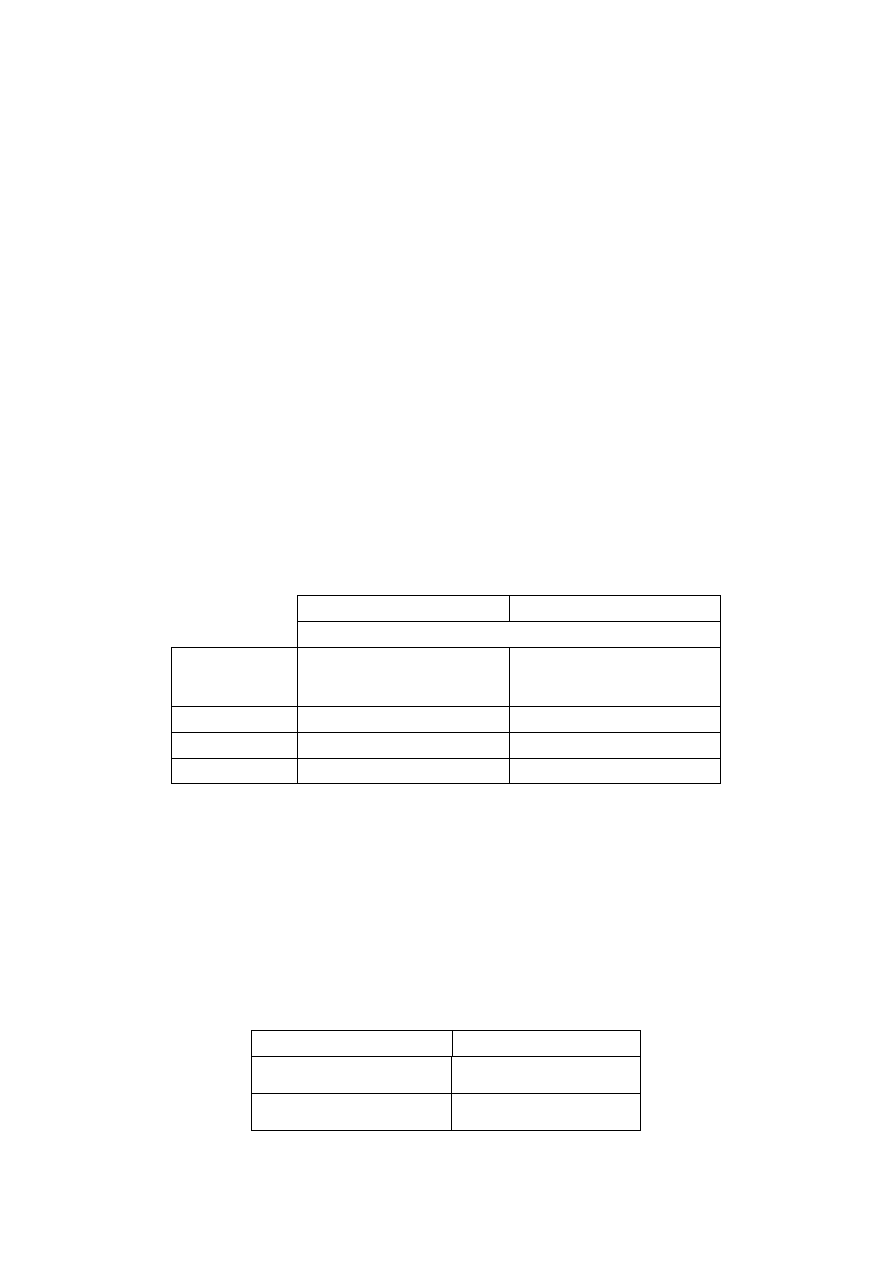
Table 3.1: Knowledge levels and corresponding methods of analysis (LS: Linear
Static, LD: Linear Dynamic) and partial safety factors (PSF).
Knowledge
Level
Geometry
Details
Materials
Analysis
PSF
KL1
Simulated
design according
to relevant
practice
and
from limited in-
situ inspection
Default values
according to
standards of the
time of
construction
and
from limited in-
situ testing
LS-LD
increased
KL2
From
incomplete
original
executive
construction
drawings with
limited in-situ
inspection
or
from extended
in-situ
inspection
From original
design
specifications
with limited in-
situ testing
or
from extended
in-situ testing
All
code
KL3
From original
architectural
drawings with
sample visual
survey
or
from full
survey
From original
executive
construction
drawings with
limited in-situ
inspection
or
from
comprehensive
in-situ
inspection
From original
test reports with
limited in-situ
testing
or
from
comprehensive
in-situ testing
All
decrease
d
3.3.1 KL1: Limited knowledge
(1)
The knowledge level is referred to the following three items:
i) geometry: the structure’s geometry is known either from survey or from original
architectural drawings. In this latter case, a sample visual survey should be performed in
order to check that the actual situation of the structure corresponds to the information
contained in the drawings and has not changed from the time of construction. The
information collected regards elements dimensions, beams spans and columns heights
and is sufficient to build a structural model for linear analysis.

Revised Final PT Draft (pre Stage 49)
Page 17
Draft July 2003
prEN 1998-3:200X
ii) details: the structural details are not known from original construction drawings and
should be assumed based on simulated design according to usual practice of the time of
construction. Limited in-situ inspections in the most critical elements should be
performed to check that the assumptions correspond to the actual situation. The
information collected should be sufficient to perform local verifications.
iii) materials: no direct information on the mechanical properties of the construction
materials is available, neither from original design specifications nor from original test
reports. In this case, default values should be assumed according to standards of the
time of construction, accompanied by limited in-situ testing in the most critical
elements.
(2)
Structural evaluation based on a state of limited knowledge shall be performed
through linear analysis methods, either static or dynamic (see 4.4). The relevant partial
safety factors for the material properties shall be appropriately increased (see 3.5).
3.3.2 KL2: Normal knowledge
(1)
The knowledge level is referred to the following three items:
i)
geometry: the structure’s geometry is known either from survey or from original
architectural drawings. In this latter case, a sample visual survey should be performed in
order to check that the actual situation of the structure corresponds to the information
contained in the drawings and has not changed from the time of construction. The
information collected regards elements dimensions, beams spans and columns heights
and is sufficient, together with those regarding the details, to build a structural model for
either linear or nonlinear analysis.
ii)
details: the structural details are known either from extended in-situ inspection or
from incomplete original executive construction drawings. In the latter case, limited in-
situ inspections in the most critical elements should be performed to check that the
available information correspond to the actual situation. The information collected
should be sufficient for either performing local verifications or setting up a nonlinear
structural model.
iii) materials: information on the mechanical properties of the construction materials is
available either from extended in-situ testing or from original design specifications. In
this latter case, limited in-situ testing should be performed. The information collected
should be sufficient for either performing local verifications or setting up a nonlinear
structural model.
(2)
Structural evaluation based on a state of normal knowledge shall be performed
through either linear or nonlinear analysis methods, either static or dynamic (see 4.4).
The relevant partial safety factors for the material properties shall be taken equal to those
given in EN 1998-1 (see 3.5).
3.3.3 KL3: Full knowledge
(1)
The knowledge level is referred to the following three items:

Revised Final PT Draft (pre Stage 49)
Page 18
Draft July 2003
prEN 1998-3:200X
i)
geometry: the structure’s geometry is known either from survey or from original
architectural drawings. In this latter case, a sample visual survey should be performed in
order to check that the actual situation of the structure corresponds to the information
contained in the drawings and has not changed from the time of construction. The
information collected regards elements dimensions, beams spans and columns heights
and is sufficient, together with those regarding the details, to build a structural model for
both linear and nonlinear analysis.
ii)
details: the structural details are known either from comprehensive in-situ
inspection or from original executive construction drawings. In the latter case, limited
in-situ inspections in the most critical elements should be performed to check that the
available information correspond to the actual situation. The information collected
should be sufficient for either performing local verifications or setting up a nonlinear
structural model.
iii) materials: information on the mechanical properties of the construction materials is
available either from comprehensive in-situ testing or from original test reports. In this
latter case, limited in-situ testing should be performed. The information collected
should be sufficient for either performing local verifications or setting up a nonlinear
structural model.
(2)
Structural evaluation based on a state of full knowledge shall be performed
through either linear or nonlinear analysis methods, either static or dynamic (see 4.4).
The relevant partial safety factors for the material properties shall be appropriately
decreased (see 3.5).
3.4 Identification of the Knowledge Level
3.4.1 Geometry
3.4.1.1 Original Architectural Drawings
(1)
The original architectural drawings are those documents that describe the
geometry of the structure, allowing for identification of structural components and their
dimensions, as well as the structural system to resist both vertical and lateral actions.
3.4.1.2 Original Executive Construction Drawings
(1)
The original executive drawings are those documents that describe the geometry
of the structure, allowing for identification of structural components and their
dimensions, as well as the structural system to resist both vertical and lateral actions. In
addition, it contains information about details (as specified in 3.3).
3.4.1.3 Visual Survey
(1)
A visual survey is a procedure for checking correspondence between the actual
geometry of the structure with the available original architectural drawings. Sample
geometry measurements on selected elements should be carried out. Possible structural
changes occurred during or after construction should be object of a survey as in 3.4.1.4.

Revised Final PT Draft (pre Stage 49)
Page 19
Draft July 2003
prEN 1998-3:200X
3.4.1.4 Full Survey
(1)
A full survey is a procedure resulting in the production of architectural drawings
that describe the geometry of the structure, allowing for identification of structural
components and their dimensions, as well as the structural system to resist both vertical
and lateral actions.
3.4.2 Details
(1)
Reliable non-destructive methods can be adopted in the inspections specified
below.
3.4.2.1 Simulated Design
(1)
A simulated design is a procedure resulting in the definition of the amount and
layout of reinforcement, both longitudinal and transverse, in all elements participating in
the vertical and lateral resistance of the building. The design should be carried out based
on regulatory documents and state of the practice used at the time of construction.
3.4.2.2 Limited in-situ Inspection
(1)
A limited in-situ inspection is a procedure for checking correspondence between
the actual details of the structure with either the available original executive construction
drawings or the results of the simulated design in 3.4.2.1. This involves performing
inspections as indicated in Table 3.2.
3.4.2.3 Extended in-situ Inspection
(1)
An extended in-situ inspection is a procedure used when the original executive
construction drawings are not available. This involves performing inspections as
indicated in Table 3.2.
3.4.2.4 Comprehensive in-situ Inspection
(1)
A comprehensive in-situ inspection is a procedure used when the original
executive construction drawings are not available and when a higher knowledge level is
sought. This involves performing inspections as indicated in Table 3.2.
3.4.3 Materials
(1)
Non-destructive test methods cannot be used in place of test methods on
material samples extracted from the structure.
3.4.3.1 Limited in-situ Testing
(1)
A limited in-situ testing is a procedure for complementing the information on
material properties derived either from the standards of the time of construction, or from
original design specifications, or from original test reports. This involves performing
tests as indicated in Table 3.2. However, if values from tests are lower than default
values according to standards of the time of construction, an extended in-situ testing is
required.
Revised Final PT Draft (pre Stage 49)
Page 20
Draft July 2003
prEN 1998-3:200X
3.4.3.2 Extended in-situ Testing
(1)
An extended in-situ testing is a procedure for obtaining information when both
original design specification and test reports are not available. This involves performing
tests as indicated in Table 3.2.
3.4.3.3 Comprehensive in-situ Testing
(1)
A comprehensive in-situ testing is a procedure for obtaining information when
both original design specification and test reports are not available and when a higher
knowledge level is sought. This involves performing tests as indicated in Table 3.2.
3.4.4 Definition of the levels of inspection and testing
(1)P
The classification of the levels of inspection and testing depend on the
percentage of structural elements that have to be checked for details as well as on the
number of material samples per floor that have to taken for testing.
NOTE: The amount of inspection and testing to be used in a country may be found in its National
Annex. For ordinary situations the recommended minimum values are given in Table 3.2. There
might be cases requiring modifications to increase some of them. These cases will be indicated in
the National Annex.
Table 3.2: Recommended minimum requirements for different levels of inspection and testing.
Inspection (of details)
Testing (of materials)
For each type of primary element (beam, column, wall):
Level of
inspection and
testing
Percentage of elements that are
checked for details
Material samples per floor
Limited
20
1
Extended
50
2
Comprehensive
80
3
3.5 Partial Safety Factors
(1)
Based on the knowledge level achieved through the different levels of survey,
inspection and testing, the values of the partial safety factors (PSF) shall be established.
NOTE: The values ascribed to the partial safety factors to be used in a country in the verifications
of brittle elements may be found in its National Annex. Recommended values are shown in Table
3.3. In no case shall the value of the reduced PSF be lower than 1,0.
Table 3.3: Recommended values of the partial safety factors (PSF) used for verifications, according
to the different knowledge levels (KL).
Knowledge Level
Partial safety factors
KL1
1,20
m
γ
KL2
m
γ
as in EN1998-1

Revised Final PT Draft (pre Stage 49)
Page 21
Draft July 2003
prEN 1998-3:200X
KL3
0,80
m
γ

Revised Final PT Draft (pre Stage 49)
Page 22
Draft July 2003
prEN 1998-3:200X
4 ASSESSMENT
4.1 General
(1)
Assessment is a quantitative procedure by which it is checked whether an
existing undamaged or damaged building can resist the design seismic load combination
as specified in this code.
(2)P
Within the scope of this Standard, assessment is made for individual buildings,
in order to decide about the need for structural intervention and about the strengthening
or repair measures to be implemented.
(3)P
The assessment procedure shall be carried out by means of the general analysis
methods foreseen in EN 1998-1 (4.3), as modified in this standard to suit the specific
problems encountered in the assessment.
(4)
Whenever possible, the method used should incorporate information of the
observed behaviour of the same type of building or similar buildings during previous
earthquakes.
4.2 Seismic action and seismic load combination
(1)P
The basic models for the definition of the seismic motion are those presented in
3.2.2 and 3.2.3 of EN 1998-1.
(2)P
Reference is made in particular to the elastic response spectrum given in 3.2.2.2
of EN 1998-1, scaled with the values of the design ground acceleration established for
the verification of the different Limit States. The alternative representations given in
3.2.3 of EN 1998-1 in terms of either artificial or recorded accelerograms are also
applicable.
(3)P
In the q-factor approach (see 2.2.1), the design spectrum for elastic analysis is
obtained from the elastic response spectrum given in 3.2.2.2 of EN 1998-1, as indicated
in 3.2.2.5 of EN 1998-1. A value of q = 1,5 shall be adopted irrespectively of the material
and of the structural type.
(4)P
The design seismic action shall be combined with the other appropriate
permanent and variable actions in accordance with the rule given in 3.2.4 of EN 1998-1.
4.3 Structural modelling
(1)P
Based on the information collected as indicated in 3.2, a model of the structure
shall be set up. The model shall be adequate for determining the action effects in all
structural elements under the seismic load combination given in 4.2.
(2)P
All provisions of EN 1998-1 regarding modelling (4.3.1) and accidental torsional
effects (4.3.2) apply without modifications.
(3)P
Some of the existing structural elements can be designated as “secondary”, in
accordance to the definitions given in 4.2.2 of EN 1998-1, items (1)P, (2) and (3).

Revised Final PT Draft (pre Stage 49)
Page 23
Draft July 2003
prEN 1998-3:200X
(4)
The strength and the stiffness of these elements against lateral actions may in
general be neglected, but they shall be checked to maintain their integrity and capacity
of supporting gravity loads when subjected to the design displacements, with due
allowance for 2
nd
order effects. Consideration of these elements in the overall structural
model, however, is advisable in the case of nonlinear types of analysis. The choice of
the elements to be considered as secondary can be varied after the results of a
preliminary analysis, but in no case the selection of these elements shall be such as to
change the classification of the structure from non regular to regular, according to the
definitions given in 4.2.3 of EN 1998-1.
4.4 Methods of analysis
4.4.1 General
(1)
The seismic action effects, to be combined with the effects of the other
permanent and variable loads according to the seismic combination in 4.2, may be
evaluated using one of the following methods:
−
lateral force analysis (linear),
−
multi-modal response spectrum analysis (linear),
−
non-linear static analysis,
−
non-linear time history dynamic analyses.
(2)
The seismic action to be used is the one corresponding to the elastic (i.e., un-
reduced by the behaviour factor q) response spectrum in 3.2.2.2 of EN 1998-1, or its
equivalent alternative representations given in 3.2.3 of EN 1998-1, respectively, factored
by the appropriate importance factor
I
γ
(see 4.2.5 of EN 1998-1).
(3)
In the q-factor approach, the seismic action for use in the linear types of analyses
is the one defined in 4.2.
(4)
The values of the material properties required for the analysis of the structure,
using either linear or non-linear methods, shall be the mean values from the in-situ
collected data.
(5)
Non-linear analyses shall be properly substantiated with respect to the
definitions of the seismic input, to the structural model adopted, to the criteria for the
interpretation of the results of the analysis, and to the requirements to be met.
(6)
The above-listed methods of analysis are applicable subject to the conditions
specified in 4.4.2-4.4.5, with the exception of masonry structures for which appropriate
procedures accounting for the peculiarities of this construction typology need to be
used. Information on these procedures may be found in the relevant material-related
Annex.
4.4.2 Lateral force analysis
(1)P
The conditions for this method to be applicable are given in 4.3.3.2.1 of EN
1998-1, with the addition of the following:

Revised Final PT Draft (pre Stage 49)
Page 24
Draft July 2003
prEN 1998-3:200X
−
denoting by
ρ
i
= D
i
/C
i
the ratio between the bending moment demand D
i
obtained
from the analysis under the seismic load combination, and the corresponding
capacity C
i
for the i-th primary element of the structure (
1
</
i
ρ
), and by
ρ
max
and
ρ
min
the maximum and minimum values of
ρ
i
, respectively, over all primary elements
of the structure, the ratio
ρ
max
/
ρ
min
does not exceed the value of 2 to 3
NOTE: The value ascribed to this limit of
ρ
max
/
ρ
min
for use in a country (within the range
indicated above) may be found in its National Annex. The recommended value is the one
underlined.
−
furthermore, the capacity C
i
of the “brittle” components is larger than the
corresponding demand D
i
, this latter evaluated either from the strength of the
adjoining ductile components, if their
ρ
i
is larger than 1, or from the analysis, if their
ρ
i
is lower than 1.
(2)P
The method shall be applied as described in 4.3.3.2.2/3/4 of EN 1998-1, except
that the response spectrum in expression (4.3) shall be the elastic spectrum
)
(
1
T
S
e
instead of the design spectrum
)
(
1
T
S
d
.
4.4.3 Multi-modal response spectrum analysis
(1)P
The conditions of applicability for this method are given in 4.3.3.3.1 of EN 1998-
1 with the addition of the conditions specified in 4.4.2.
(2)P
The method shall be applied as described in 4.3.3.3.2/3 of EN 1998-1, using the
elastic response spectrum
)
(
1
T
S
e
.
4.4.4 Nonlinear static analysis
(1)P
Nonlinear static (pushover) analysis is a non-linear static analysis under constant
gravity loads and monotonically increasing horizontal loads.
(2)P
Buildings not complying with the criteria of 4.3.3.4.2.1(2), (3) of EN 1998-1 for
regularity in plan shall be analysed using a spatial model.
(3)P
For buildings complying with the regularity criteria of 4.2.3.2 of EN 1998-1 the
analysis may be performed using two planar models, one for each main direction.
4.4.4.1 Lateral loads
(1)
At least two vertical distributions of lateral loads should be applied:
−
a “uniform” pattern, based on lateral forces that are proportional to mass regardless
of elevation (uniform response acceleration)
−
a “modal” pattern, proportional to lateral forces consistent with the lateral force
distribution determined in elastic analysis
(2)
Lateral loads shall be applied at the location of the masses in the model.
Accidental eccentricity should be considered.

Revised Final PT Draft (pre Stage 49)
Page 25
Draft July 2003
prEN 1998-3:200X
4.4.4.2 Capacity curve
(1)
The relation between base-shear force and the control displacement (the
“capacity curve”) should be determined as indicated in 4.3.3.4.2.3(1), (2) of EN 1998-1.
4.4.4.3 Target displacement
(1)P
Target displacement is defined as seismic demand in terms of the displacement
defined in 4.3.3.4.2.6(1) of EN 1998-1.
NOTE: Target displacement may be determined according to the (informative) Annex B of EN
1998-1.
4.4.4.4 Procedure for estimation of the torsional effects
(1)P
The procedure given in 4.3.3.4.2.7(1) to (3) applies.
4.4.5 Nonlinear time-history analysis
(1)P
The procedure given in 4.3.3.4.3(1) to (3) applies.
4.4.6 Combination of the components of the seismic action
(1)P
The two horizontal components of the seismic action shall be combined
according to 4.3.3.5.1 of EN 1998-1.
(2)P
The vertical component of the seismic action shall be considered in the cases
contemplated in 4.3.3.5.2 of EN 1998-1 and, when appropriate, combined with the
horizontal components as indicated in the same clause.
4.4.7 Additional measures for masonry infilled structures
(1)
Provisions of 4.3.6 of EN 1998-1 apply, whenever relevant
4.4.8 Combination coefficients for variable actions
(1)
Provisions of 4.2.4 of EN 1998-1 apply
4.4.9 Importance categories and importance factors
(1)
Provisions of 4.2.5 of EN 1998-1 apply.
4.5 Safety verifications
4.5.1 Linear methods of analysis (static or dynamic)
(1)P
The demands on “ductile” components shall be those obtained from the analysis
performed according to 4.4.2 or 4.4.3.
(2)P
“Brittle” components/mechanisms shall be verified with two alternative
demands D: either the value obtained from the analysis, if the ductile components with
capacity C, delivering load to them, satisfy
1
/
≤
C
D
, or the value obtained by means of

Revised Final PT Draft (pre Stage 49)
Page 26
Draft July 2003
prEN 1998-3:200X
equilibrium conditions, considering the strength of the ductile components delivering
load to the brittle component under consideration, evaluated using mean values of
material properties without partial safety factors
m
γ
.
(3)
Information on the evaluation of the capacity for both ductile and brittle
components and mechanisms can be found in the relevant material-related Annexes,
taking into account of 2.2.1(4).
4.5.2 Nonlinear methods of analysis (static or dynamic)
(1)P
The demands on both “ductile” and “brittle” components shall be those
obtained from the analysis performed according to 4.4.4 or 4.4.5.
(2)
Information on the evaluation of the capacity for both ductile and brittle
components and mechanisms can be found in the relevant material-related Annexes,
taking into account of 2.2.1(4).

Revised Final PT Draft (pre Stage 49)
Page 27
Draft July 2003
prEN 1998-3:200X
5 DECISIONS FOR STRUCTURAL INTERVENTION
5.1 Criteria for a structural intervention
(1)
On the basis of the conclusions of the assessment of the structure and/or the
nature and extent of the damage, decisions should be taken, seeking to minimise the
cost of intervention and to optimise social interests.
(2)
This Standard describes the technical aspects of the relevant criteria.
5.1.1 Technical criteria
(1)P
The selection of the type, technique, extent and urgency of the intervention shall
be based on the structural information collected during the assessment of the building.
(2)
The following aspects should be considered:
a) All identified local gross errors should be appropriately remedied.
b) In case of highly irregular buildings (both in terms of stiffness and overstrength
distributions), their structural regularity should be improved as much as possible,
both in elevation and in plan.
c) The required characteristics of regularity and resistance can be achieved by either
direct strengthening of a (reduced) number of deficient components, or by the
insertion of new lateral load-resisting elements.
d) The increase of local ductility should be sought where needed.
e) The increase in strength after the intervention should not reduce the necessary
global available ductility.
f) Specifically for masonry structures: non-ductile lintels should be replaced,
inadequate connections between floor and walls should be improved, horizontal
thrusts against walls should be eliminated.
5.1.2 Type of intervention
(1)
An intervention may be selected from the following indicative types; one or
more types in combination may be selected. In all cases, the effect of structural
modifications on the foundation shall be considered.
a) Local or overall modification of damaged or undamaged elements (repair,
strengthening or full replacement), considering their stiffness, strength and/or
ductility.
b) Addition of new structural elements (e.g. bracings or infill walls; steel, timber or
reinforced concrete belts in masonry construction; etc).

Revised Final PT Draft (pre Stage 49)
Page 28
Draft July 2003
prEN 1998-3:200X
c) Modification of the structural system (elimination of some structural joints;
widening of joints; elimination of vulnerable elements; modification into more
regular and/or more ductile arrangements)
5
.
d) Addition of a new structural system to sustain the entire seismic action.
e) Possible transformation of existing non-structural elements into structural
elements.
f) Introduction of passive protection devices through either dissipative bracing or
base isolation.
g) Mass reduction.
h) Restriction or change of use of the building.
i) Partial demolition.
(2)P
In case base isolation is adopted, the provisions contained in Section 10 of EN
1998-1 shall be followed.
5.1.3 Non-structural elements
1(P)
Decisions regarding repair or strengthening of non-structural elements shall also
be taken whenever, in addition to functional requirements, the seismic behaviour of
these elements may endanger the life of inhabitants or affect the value of goods stored
in the building.
(2)
In such cases, full or partial collapse of these elements should be avoided by
means of:
a) Appropriate connections to structural elements (see 4.3.5 of EN1998-1).
b) Increasing the resistance of non-structural elements (see 4.3.5 of EN 1998-1).
c) Taking measures of anchorage to prevent possible falling out of parts of these
elements.
(3)
The possible consequences of these provisions on the behaviour of structural
elements should be taken into account.
5.1.4 Justification of the selected intervention type
(1)P
In all cases, the redesign documents shall include the justification of the type of
intervention selected and the description of its expected structural function and
consequences.
(2)
This justification should be made available to the person or organisation
responsible for the long-term maintenance of the structure.
5
This is for instance the case when vulnerable low shear-ratio columns or entire soft storeys are transformed into more ductile arrangements;
similarly, when overstrength irregularities in elevation, or in-plan eccentricities are reduced by modifying the structural system.

Revised Final PT Draft (pre Stage 49)
Page 29
Draft July 2003
prEN 1998-3:200X
6 DESIGN OF STRUCTURAL INTERVENTION
6.1 Redesign Procedure
(1)P
The redesign process shall cover the following steps:
a) Conceptual design
(i) Selection of techniques and/or materials, as well as of the type and configuration of
the intervention.
(ii) Preliminary estimation of dimensions of additional structural parts
(iii) Preliminary estimation of the modified stiffness of the repaired/strengthened
elements.
b) Analysis
(2)P
The methods of analysis of the structure as redesigned shall be those indicated in
4.4, as appropriate, considering the new characteristics of the building.
(3)P
In case the redesign consists in the addition of new structural elements intended
to resist the entire seismic action, the latter should be designed using the seismic action,
the method of analysis, and the verification procedures as in EN 1998-1.
c) Verifications
(4)P
Safety verifications shall be carried out in accordance with 4.5.
(5)P
For existing components, material safety factors
m
γ
shall be the same as in EN
1998-1, according to the level of knowledge specified in 3.3.

Revised Final PT Draft (pre Stage 49)
Page 30
Draft July 2003
prEN 1998-3:200X
ANNEX A (Informative)
A REINFORCED CONCRETE STRUCTURES
A.1 Scope
(1)
This section contains specific information for the assessment of reinforced
concrete buildings in their present state, and for their upgrading, when necessary.
A.2 Identification of geometry, details and materials
A.2.1 General
(1) The following aspects should be carefully examined:
i. Physical condition of reinforced concrete elements and presence of any
degradation, due to carbonation, steel corrosion, etc.
ii. Continuity of load paths between lateral resisting elements.
A.2.2 Geometry
(1)
The collected data should include the following items:
i. Identification of the lateral resisting systems in both directions.
ii. Orientation of one-way floor slabs.
iii. Depth and width of beams, columns and walls.
iv. Width of flanges in T-beams.
v. Possible eccentricities between beams and columns axes at joints.
A.2.3 Details
(1)
The collected data should include the following items:
i. Amount of longitudinal steel in beams, columns and walls.
ii. Amount and proper detailing of confining steel in critical regions and in
beam-column joints.
iii. Amount of steel reinforcement in floor slabs contributing to the negative
resisting bending moment of T-beams.
iv. Seating lengths and support conditions of horizontal elements.
v. Depth of concrete cover.

Revised Final PT Draft (pre Stage 49)
Page 31
Draft July 2003
prEN 1998-3:200X
vi. Lap-splices for longitudinal reinforcement.
A.2.4 Materials
(1)
The collected data should include the following items:
i. Concrete strength.
ii. Steel yield strength, ultimate strength and ultimate strain.
A.3 Capacity Models for Assessment
(1)
Classification of components/mechanisms:
i. “ductile”: beam-columns under flexure with and without axial force, and
walls,
ii. “brittle”: shear mechanism of beam-columns and of joints.
A.3.1 Beam-columns under flexure with and without axial force and walls
(1)
The deformation capacity of beam-columns and walls is defined as the chord
rotation
θ
, i.e., the angle between the tangent to the axis at the yielding end and the
chord connecting that end with the end of the shear span (
V
L = M/V = moment/shear),
i.e., the point of contraflexure. The chord rotation is also equal to the element drift ratio,
i.e., the deflection at the end of the shear span divided by the length.
A.3.1.1 LS of near collapse (NC)
(1)
The value of the total chord rotation capacity (elastic plus inelastic part) at
ultimate
u
θ
of concrete members under cyclic loading may be calculated from the
following expression:
)
3
.
1
(
25
)
,
01
.
0
(
max
)
'
,
01
.
0
(
max
)
3
.
0
(
0172
.
0
1
100
4
.
0
175
.
0
d
c
yw
sx
f
f
V
c
el
um
h
L
f
ρ
αρ
ν
ω
ω
⋅
γ
=
θ
(A.1)
where
el
γ
= equal to 1,5 for primary elements and 1,0 for secondary elements (as
defined in 4.3), h = depth of cross-section (equal to the diameter D for circular
sections),
c
bhf
N /
=
ν
( b width of compression zone, N axial force positive for
compression),
ω
and
ω′
= mechanical reinforcement ratio of the tension (including the
web reinforcement) and compression, respectively, longitudinal reinforcement,
c
f is the
estimated value of the concrete compressive strength (MPa),
h
w
sx
sx
s
b
A
=
ρ
= ratio of
transverse steel parallel to the direction x of loading (
h
s = stirrup spacing),
d
ρ
= steel
ratio of diagonal reinforcement (if any), in each diagonal direction,
α
= confinement
effectiveness factor, that may be taken equal to:

Revised Final PT Draft (pre Stage 49)
Page 32
Draft July 2003
prEN 1998-3:200X
−
−
−
=
α
∑
c
c
i
c
h
c
h
b
h
b
h
s
b
s
6
1
2
1
2
1
2
(A.2)
where
c
b and
c
h = dimension of confined core to the inside of the hoop,
i
b = centerline
spacing of longitudinal bars (indexed by i) laterally restrained by a stirrup corner or a
cross-tie along the perimeter of the cross-section.
In walls the value given by (A.1) is multiplied by 0.625.
If cold-worked brittle steel is used the value given by (A.1) is multiplied by 0,62 (i.e. it
becomes equal to 0,011).
In members without detailing for earthquake resistance the value given by (A.1) is
divided by 1,2; moreover, if stirrups are not closed with 135° hoops,
α
is taken equal to
zero.
(2) The value of the plastic part of the chord rotation capacity of concrete members
under cyclic loading may be calculated from the following expression:
)
3
.
1
(
25
)
,
01
.
0
(
max
)
'
,
01
.
0
(
max
)
2
.
0
(
0129
.
0
1
100
375
.
0
225
.
0
d
c
yw
sx
f
f
V
c
el
y
um
pl
um
h
L
f
ρ
αρ
ν
ω
ω
γ
θ
θ
θ
⋅
⋅
⋅
=
−
=
(A.3)
where the chord rotation at yielding,
y
θ
, should be calculated according to (A.13), and
all other variables are defined as for (A.1).
In walls the value given by (A.3) is multiplied by 0.6.
If cold-worked brittle steel is used the value given by (A.3) is multiplied by 0,41, i.e. the
coefficient becomes 0,0053.
In members without detailing for earthquake resistance the value given by (A.3) is
divided by 1,15; moreover, if stirrups are not closed with 135° hoops,
α
is taken equal
to zero.
(3)
For the evaluation of the ultimate chord rotation an alternative equation may be
used:
−
φ
−
φ
+
θ
=
θ
V
pl
pl
y
u
y
um
L
L
L
5
.
0
1
)
(
(A.4)
where
y
θ
is the chord rotation at yield as defined in (A.11),
u
φ
is the ultimate curvature
computed considering the compressive concrete strain at its ultimate value
cu
ε
,
y
φ
is
the yield curvature computed considering the tensile steel strain at its yield value
sy
ε
.

Revised Final PT Draft (pre Stage 49)
Page 33
Draft July 2003
prEN 1998-3:200X
The value of the length
pl
L of the plastic hinge depends on how the enhancement of
strength and deformation capacity of concrete due to confinement is taken into account
in the calculation of the ultimate curvature of the end section,
u
φ
.
If the confinement models included in prEN1992-1-1:200x are adopted (as in
prEN1998-1:200x), then for beams, columns or walls L
pl
may be calculated from
the following expressions:
)
(
036
.
0
035
.
0
06
.
0
MPa
f
d
h
L
L
y
b
V
pl
+
+
=
(A.5)
For beams or columns alone L
pl
may alternatively be calculated from either one
of the following expressions:
)
(
025
.
0
5
.
0
MPa
f
d
h
L
y
b
pl
+
=
(A.6)
If confinement models are used which represent better the improvement of the
ultimate curvature of the end section, ö
u
, under cyclic loading, such as the
original Mander model or an improvement of it, in which the ultimate strain of
the extreme fibre of the compression zone is taken as:
cc
yw
sw
w
su
cu
f
f
añ
å
5
.
1
004
.
0
å
,
+
=
(A.7)
where, å
su,w
,
f
yw
and ñ
sw
are the ultimate strain, the field stress and the volumetric
ratio of confinement reinforcement (twice the minimum transverse steel ratio of
the member in the two transverse directions), and f
cc
the concrete strength, as
enhanced by confinement, then for beams or columns L
pl
may be calculated
from either one of the following expressions:
)
(
02
.
0
125
.
0
025
.
0
MPa
f
d
h
L
L
y
b
V
pl
+
+
=
(A.8)
)
(
016
.
0
3
.
0
MPa
f
d
h
L
y
b
pl
+
=
(A.9)
Expressions (A.7)-(A.9) apply to concrete members with seismic detailing. For
old-type members without such detailing, the following expressions provide
better approximation:
For the confinement model in prEN1992-1-1:200x:
)
(
036
.
0
2
.
0
MPa
f
d
L
L
y
b
V
pl
+
=
(A.10)
For the confinement model referred to in relation to expressions (A.8), (A.9):
)
(
1
.
0
125
.
0
025
.
0
MPa
f
d
h
L
L
y
b
V
pl
+
+
=
(A.11)

Revised Final PT Draft (pre Stage 49)
Page 34
Draft July 2003
prEN 1998-3:200X
A.3.1.2 LS of severe damage (SD)
(1)
The chord rotation relative to severe damage
SD
θ
can be assumed as 3/4 of the
ultimate chord rotation
u
θ
given in (A.1) or (A.4).
A.3.1.3 LS of damage limitation (DL)
(1)
The capacity for this limit state used in the verifications is the yield bending
moment under the design value of the axial load.
(2)
In case the verification is carried out in terms of deformation the corresponding
capacity is given by the chord rotation at yielding
y
θ
, evaluated as:
c
y
b
sy
sl
el
V
y
y
f
d
d
f
d
L
)
(
2
.
0
3
′
−
ε
α
+
α
+
φ
=
θ
(A.12)
where the first two terms account for flexural and shear contributions, respectively, and
the third for anchorage slip of bars. In the above equation,
el
α
= 0.00275 for beams and
columns and
el
α
= 0,0025 for walls of rectangular, T- or barbelled section, d and d’ are
the depth to the tension and compression reinforcement, respectively, and
y
f and
c
f
are the estimated values of the steel tensile and concrete compressive strength,
respectively.
(3)
In case the verification is carried out in terms of deformation, the demand
should be obtained from an analysis on a structural model with the stiffness of the
elements given by
y
s
y
L
M
θ
, where
s
L is the distance between the support and the
point of contraflexure, which may be taken equal to half the element length.
A.3.2 Beam-columns and walls: shear
A.3.2.1 LS of near collapse (NC)
(1)
The shear resistance may be computed according to EN 1998-1.
The cyclic shear resistance, V
R
, decreases with the plastic part of ductility demand,
expressed in terms of ductility ratio of the transverse deflection of the shear span or of
the chord rotation at member end: ì
Ä
pl
=
µ
∆
-1. For this purpose
µ
∆
pl
may be calculated as
the ratio the plastic part of the chord rotation,
θ
, normalized to the chord rotation at
yielding,
θ
y
, calculated according to expression (A.12).
In units of MN and m, the reduction in shear strength with ì
Ä
pl
may be taken in
accordance to the following expression:

Revised Final PT Draft (pre Stage 49)
Page 35
Draft July 2003
prEN 1998-3:200X
(
)
( )
(
)
+
−
ρ
⋅
⋅
µ
−
⋅
+
−
=
∆
w
c
c
s
tot
pl
c
c
s
R
V
A
f
h
L
f
A
N
L
x
h
V
,
5
min
16
.
0
1
)
100
,
5
.
0
max(
,
5
min
055
.
0
1
16
.
0
55
.
0
,
min
2
(A.13)
where: h: depth of cross-section (equal to the diameter D for circular sections); x:
compression zone depth; N: compressive axial force (positive, taken as being zero for
tension); L
V
=M/V: shear span at member end; A
c
: cross-section area, taken as being
equal to b
w
d for a cross-section with a rectangular web of width (thickness) b
w
and
structural depth d, or to
π
D
c
2
/4 (where D
c
is the diameter of the concrete core to the
inside of the hoops) for circular sections; f
c
: concrete strength (Ì Pa);
ρ
tot
: total
longitudinal reinforcement ratio; V
w
: contribution of transverse reinforcement to shear
resistance, taken as being equal to:
a) for cross-sections with rectangular web of width (thickness) b
w
:
yw
w
w
w
zf
b
V
ñ
=
(A.14)
where
ρ
w
is the transverse reinforcement ratio, z the length of the internal lever
arm (taken as being equal to d-d’ in beams or columns, or to 0.75h in walls) and
f
yw
the yield stress of the transverse reinforcement,
b) for circular cross-sections:
)
2
(
2
ð
c
D
f
s
A
V
yw
sw
w
−
=
(A.15)
where A
sw
is the cross-sectional area of a circular stirrup, s the centerline spacing
of stirrups and c the concrete cover;
The shear strength of a concrete wall, V
R
, may not be taken greater than the value
corresponding to failure by web crushing, V
R,max
, which under cyclic inelastic loading
may be calculated from the following expression:
)
'
(
1
.
0
1
)
ñ
100
(
9
4
1
65
.
0
1
095
.
0
max
,
d
d
b
f
h
L
df
b
N
V
w
c
s
tot
c
w
R
−
−
+
+
=
(A.16)
The minimum of the shear resistance calculated according to EN1998-1 or by means of
expressions (A.12)-(A.15) should be used in the assessment. Mean material properties
should be used in the calculations, with the appropriate partial factors based on the
Knowledge Level for primary elements and with partial factors equal to 1,0 for
secondary elements.
A.3.2.2 LS of severe damage (SD) and of damage limitation (DL)
(1)
The verification against the exceedance of these two LS is not required, unless
these two LS are the only ones to be checked.

Revised Final PT Draft (pre Stage 49)
Page 36
Draft July 2003
prEN 1998-3:200X
A.3.3 Beam-column joints
A.3.3.1 LS of near collapse (NC)
(1)
The shear demand on the joints is evaluated according to EN 1998-1, paragraph
5.5.2.3.
(2)
The shear capacity on the joints is evaluated according to EN 1998-1, paragraph
5.5.3.3, with mean material properties with the appropriate partial safety factors based
on the Knowledge Level.
A.3.3.2 LS of severe damage (SD) and of damage limitation (DL)
(1)
The verification against the exceedance of these two LS is not required, unless
these two LS are the only ones to be checked.
A.4 Capacity Models for Strengthening
A.4.1 Concrete jacketing
(1)
Concrete jackets are applied to columns and walls for all or some of the
following purposes: increasing the bearing capacity, increasing the flexural and/or shear
strength, increasing the deformation capacity, improving the strength of deficient lap-
splices.
(2)
The thickness of the jackets should be such as to allow for placement of both
longitudinal and transverse reinforcement with an adequate cover.
(3)
When jackets aim at increasing flexural strength, longitudinal bars should be
continued to the adjacent story through holes piercing the slab, while horizontal ties
should be placed in the joint region through horizontal holes drilled in the beams. Ties
can be omitted in the case of fully confined interior joints.
(4)
When only shear strength and deformation capacity increases are of concern,
jointly with a possible improvement of lap-splicing, then jackets will be terminated
(both concreting and reinforcement) leaving a gap with the slab of the order of 10 mm.
A.4.1.1 Enhancement of strength and deformation capacities
(1)
For the purpose of evaluating strength and deformation capacities of jacketed
elements, the following approximate simplifying assumptions may be made:
- the jacketed element behaves monolithically, with full composite action between
old and new concrete;
- the fact that axial load is originally applied to the old column alone is disregarded,
and the full axial load is assumed to act on the jacketed element;

Revised Final PT Draft (pre Stage 49)
Page 37
Draft July 2003
prEN 1998-3:200X
- the concrete properties of the jacket are considered to apply over the full section of
the element.
(2)
The following relations may be assumed to hold between the values of
R
V ,
y
M ,
y
θ
, and
u
θ
, calculated under the assumption above and the values to be adopted in
design:
R
R
V
V
9
.
0
=
∗
(A.17)
y
y
M
M
9
.
0
=
∗
(A.18)
y
y
θ
=
θ
∗
9
.
0
(A.19)
u
u
θ
=
θ
∗
0
.
1
(A.20)
A.4.2 Steel jacketing
(1)
Steel jackets are applied to columns with the purpose of: increasing shear
strength, improve the strength of deficient lap-splices, and increase ductility through
confinement.
(2)
Steel jackets around rectangular columns are usually made up of four corner
angles to which either continuous steel plates, or thicker discrete horizontal steel straps,
are welded. Corner angles may be epoxy-bonded to the concrete, or just made to adhere
to it without gaps along the entire height. Straps may be pre-heated just prior to welding,
in order to provide afterwards some positive confinement on the column.
A.4.2.1 Shear strength
(1)
The contribution of the jacket to shear strength may be considered as additive to
existing strength, provided the jacket remains well within the elastic range. This
condition is necessary for the jacket to be able to control the width of internal cracks
and to ensure the integrity of the concrete, thus allowing the original shear resisting
mechanism to continue to operate.
(2)
If only 50% of the steel yield strength of the jacket is used, the expression for the
additional shear
j
V carried by the jacket is:
α
=
cos
1
2
5
.
0
yw
j
j
f
s
b
t
V
(A.21)
where
j
t , b, s are thickness, width and spacing of the steel straps, respectively, (b/s = 1,
in case of continuous steel plates).
Revised Final PT Draft (pre Stage 49)
Page 38
Draft July 2003
prEN 1998-3:200X
A.4.2.2 Confinement action
(1)
The confining effect of a steel jacket may be evaluated in the same way as for
hoops and ties, using for the geometric steel ratio in each transverse direction, the cross-
sectional area of steel relative to a vertical section through the column.
(2)
For the properties of confined concrete, the expression provided in 3.1.9 of
ENV1992-1 may be used.
(3)
Alternatively, the strength of confined concrete may be evaluated from:
ρ
α
+
=
87
.
0
5
.
0
7
.
3
1
cd
yw
s
cd
cc
f
f
f
f
(A.22)
where
s
ρ
and
yw
f
are the geometric steel ratio and yield strength of the jacketing steel,
respectively, and
α
is the so-called efficiency factor given by the ratio of the confined
(shaded) concrete area to the total area in Figure 1.
Figure 1. Effectively confined area.
(4)
The ultimate deformation of concrete corresponding to (A.21) is given by
expression (A.7).
A.4.2.3 Clamping of lap-splices
(1)
Steel jackets can provide effective clamping in the regions of lap-splices, so as to
achieve high cyclic deformation capacity. For this result to be obtained it is necessary
that:
−
the length of the jacket exceeds by no less than 50% the length of the splice region,
−
the jacket is pressured against the faces of the column by at least two rows of bolts
on each side normal to the direction of loading,
−
when splicing occurs at the base of the column, the rows of bolts should be located
one at the top of the splice region and another at 1/3 of that region, starting from the
base.

Revised Final PT Draft (pre Stage 49)
Page 39
Draft July 2003
prEN 1998-3:200X
A.4.3 FRP plating and wrapping
(1)
Externally bonded FRP have been used extensively in retrofitting reinforced
concrete structures, though mostly in non-seismic cases. The main uses of FRP in
seismic strengthening of existing reinforced concrete elements are the following:
−
Enhancement of the shear capacity of columns and walls, by applying externally
bonded FRP with the fibers in the hoop direction;
−
Enhancement of the available ductility at beam or column ends, through added
confinement in the form of FRP jackets, with the fibers placed along the perimeter;
−
Prevention of lap splicing, through increased lap confinement again with the fibers
along the perimeter.
A.4.3.1 Shear strength
(1)
Shear capacity of brittle components can be enhanced in beams, columns or
shear walls through the application of FRP sheets. These can be applied either by fully
wrapping the element, or by bonding them to the sides and the soffit of the beam (U-
shaped sheet), or by bonding them to the sides only.
(2)
The shear capacity is evaluated as the sum of three contributions, of concrete, of
steel transverse reinforcement, and of FRP:
f
w
c
R
V
V
V
V
+
+
=
(A.23)
where
c
V and
w
V , the concrete and steel contributions, respectively, are evaluated
according to EN 1992-1.
(3)
For rectangular sections, the FRP contribution is evaluated as:
(
)
β
⋅
β
+
⋅
ε
⋅
⋅
ρ
⋅
⋅
=
sin
cot
1
9
.
0
,e
f
f
f
w
f
E
b
d
V
(A.24)
where d is the section depth,
w
b is the minimum width of cross section over the
effective depth,
w
f
f
b
t
β
=
ρ
sin
2
is the FRP reinforcement ratio (where
f
t is the FRP
thickness),
f
E is the FRP elastic modulus in the principal fiber orientation,
β
is the
angle between principal fiber orientation and longitudinal axis of element, and
006
.
0
,
≤
ε
e
f
is the effective strain, defined as:
−
For fully wrapped (i.e., closed) or properly anchored (in the compression zone)
CFRP (carbon fiber) jackets:
fu
f
f
c
e
f
E
f
ε
ρ
⋅
=
ε
30
.
0
3
2
,
17
.
0
(A.25)
−
For side or U-shaped (i.e., open) CFRP jackets:

Revised Final PT Draft (pre Stage 49)
Page 40
Draft July 2003
prEN 1998-3:200X
ε
ρ
⋅
ρ
⋅
⋅
=
ε
−
fu
f
f
c
f
f
c
e
f
E
f
E
f
30
.
0
3
2
56
.
0
3
2
3
,
17
.
0
;
10
65
.
0
min
(A.26)
−
For fully wrapped (i.e., closed) or properly anchored (in the compression zone)
AFRP (aramid fiber) jackets:
fu
f
f
c
e
f
E
f
ε
ρ
⋅
=
ε
47
.
0
3
2
,
048
.
0
(A.27)
where
c
f is the estimated value of the concrete compressive strength, and
fu
ε
is the
ultimate strain of FRP. Note that
c
f and
f
E should be expressed in MPa and GPa,
respectively.
(4)
For circular sections, the FRP contribution is evaluated as:
e
f
f
f
c
f
E
A
V
,
5
.
0
ε
⋅
⋅
ρ
⋅
=
(A.28)
where
c
A is the column cross-section area, and
004
.
0
,
=
ε
e
f
.
A.4.3.2 Confinement action
(1)
The enhancement of deformation capacity is achieved through concrete
confinement by means of FRP jackets. These are applied around the element to be
strengthened in the potential plastic hinge region.
(2)
The necessary amount of confinement pressure to be applied depends on the
ratio
ava
tar
I
,
,
χ
χ
χ
µ
µ
=
, between the target curvature ductility
tar
,
χ
µ
and the available
curvature ductility
ava
,
χ
µ
, and can be evaluated as:
5
.
1
2
2
4
.
0
ju
cu
cd
l
f
I
f
ε
ε
⋅
=
χ
(A.29)
where
cd
f
is the concrete design strength,
cu
ε
is the concrete ultimate strain and
ju
ε
is
the adopted FRP jacket ultimate strain, which is lower than the ultimate strain of FRP
fu
ε
.
(3)
For the case of circular cross-sections wrapped with continuous sheets (not in
strips), the confinement pressure is related to the amount of FRP sheet
j
ρ
through:
ju
j
j
l
E
f
ε
ρ
=
2
1
, with
j
E being the jacket elastic modulus. The thickness of the FRP
jacket can be calculated as:
4
j
j
j
d
t
ρ
=
, where
j
d is the diameter of the jacket around
the circular cross-section.

Revised Final PT Draft (pre Stage 49)
Page 41
Draft July 2003
prEN 1998-3:200X
(4)
For the case of rectangular cross-sections in which the corners have been
rounded to allow wrapping the FRP around them, the confinement pressure is evaluated
as:
l
s
l
f
k
f
=
′
, with
D
R
k
c
s
2
=
and
D
t
E
f
j
ju
j
l
ε
=
2
, where D is the larger section
width.
(5)
For the case of wrapping applied through strips with spacing
f
s , the
confinement pressure is evaluated as:
l
g
l
f
k
f
=
′
, with
2
)
2
/
1
(
D
s
k
f
g
−
=
.
A.4.3.3 Clamping of lap-splices
(1)
Slippage of lap-splices can be prevented by applying a lateral pressure
l
σ
through FRP jackets. For circular columns, having diameter D, the necessary thickness
may be estimated as:
001
.
0
2
)
(
⋅
σ
−
σ
=
j
sw
l
f
E
D
t
(A.30)
where
sw
σ
is the hoop stress in the stirrups at a strain of 0.001, or the active pressure
from the grouting between the FRP and the column, if provided, while
sw
σ
represents
the clamping stress over the lap-splice length
s
L , as given by:
s
b
yd
s
l
L
c
d
n
p
f
A
+
+
=
σ
)
(
2
2
(A.31)
where
s
A and
yd
f
are the area and the design yield strength of longitudinal steel
reinforcement, respectively, p is the perimeter line in the column cross-section along the
inside of longitudinal steel, n is the number of spliced bars along p,
b
d is the largest
diameter of longitudinal steel bars, and c is the concrete cover thickness.
(2)
For rectangular columns, the expressions above may be used by replacing D by
w
b , the section width, and by reducing the effectiveness of FRP jacketing by means of
the coefficient in the previous paragraph, item 4).

Revised Final PT Draft (pre Stage 49)
Page 42
Draft July 2003
prEN 1998-3:200X
ANNEX B (Informative)
B STEEL AND COMPOSITE STRUCTURES
B.1 Scope
This section contains information for the assessment of steel and composite framed
buildings in their present state and for their upgrading, when necessary.
EN 1992-1, EN 1993-1, EN 1994-1 and EN 1998-1 apply as minimum requirements
while the information which is provided in this Annex is complementary or more
stringent requirements.
Seismic retrofitting may be either local or global.
B.2 Identification of geometry, details and materials
B.2.1 General
(1) The following aspects should be carefully examined:
i. Current physical conditions of base metal and connector materials
including the presence of distortions.
ii. Current physical condition of primary and secondary components
including the presence of any degradation.
iii. Condition of assessment of existing buildings site condition.
B.2.2 Geometry
(1) The collected data should include the following items:
i. Identification of the lateral resisting systems.
ii. Identification of horizontal diaphragms.
iii. Original cross-sectional shape and physical dimensions.
iv. Existing cross sectional area, section moduli, moment of inertia, and torsional
properties at critical sections.

Revised Final PT Draft (pre Stage 49)
Page 43
Draft July 2003
prEN 1998-3:200X
B.2.3 Details
(1) The collected data should include the following items:
i. Size and thickness of additional connected materials, including cover plates,
bracing and stiffeners.
ii. Amount of longitudinal and transverse reinforcement steel in composite beams,
columns and walls.
iii. Amount and proper detailing of confining steel in critical regions.
iv. As built configuration of intermediate, splice and end connections.
B.2.4 Materials
(1) The collected data should include the following items:
i. Concrete strength.
ii. Steel yield strength, strain hardening, ultimate strength and elongation.
Areas of reduced stress, such as flange tips at beam-column ends and external plate
edges, should be selected for inspection as far as possible.
To evaluate material properties, samples should be removed from web plates of hot
rolled profiles for components designed as dissipative.
Flange plate specimens should be used to characterise the material properties of non
dissipative members and/or connections.
Gamma radiography, ultrasonic testing through the architectural fabric or boroscopic
review through drilled access holes are viable testing methods when accessability is
limited or for composite components.
Soundness of base and filler materials should be proved on the basis of chemical and
metallurgical data.
Charpy V-Notch toughness tests should prove that heat affected zones, if any, and
surrounding material have adequate resistance for brittle fracture.
Destructive and/or non destructive tests (liquid penetrant, magnetic particle, acoustic
emission) and ultrasonic or tomographic methods can be used.
B.3 Requirements on geometry and materials
B.3.1 Geometry
(1)
Steel sections should satisfy width-to-thickness slenderness limitations based on
class section classification as in Sections 6 and 7 of EN 1998-1. The relationship
between limit states and section classification is provided in Table B.1.

Revised Final PT Draft (pre Stage 49)
Page 44
Draft July 2003
prEN 1998-3:200X
Table B.1. - Relationship between limit states and section classes.
Limit state
Class of Section
SD
2
NC
1
(1)
The transverse links enhance the rotation capacities of beam-columns even with
slender flanges and webs. Such transverse bars should be welded between the flanges in
compliance with EN 1998-1 Section 7.6.5.
The transverse links should be spaced as transverse stirrups used for encased members.
B.3.2 Materials
B.3.2.1 Structural Steel
(1) Steel grades as in EN 1998-1 should be used for new parts or to replace existing
structural components.
Specified maximum yield strength should be used to design dissipative components that
are expected to yield during design earthquake.
The effects of composite action should be to evaluate the strength and stiffness of the
structural components at each LS.
The through-thickness resistance in column flanges should be based upon the reduced
strength as follows:
y
u
f
0.90
f
⋅
=
(B.1)
Base material with thickness greater than 40mm should possess toughness not less than
27J measured at 20
o
C. Charpy V-Notch (CVN) tests are adequate to perform toughness
tests.
Weld metal CVN toughness should be not less than 27J measured at -30
o
C.
In wide flange sections coupons should be cut from intersection zones between flange
and web. This is an area (k-area) of potentially reduced notch toughness because of the
slow cooling process during fabrication.
B.3.2.2 Reinforcement Steel
(1) Reinforcement steel for new and existing RC parts should satisfy the requirements
in Table 2.1 of EN 1998-1. Ductility class H should be used for dissipative and non
dissipative zones.

Revised Final PT Draft (pre Stage 49)
Page 45
Draft July 2003
prEN 1998-3:200X
B.3.2.3 Concrete
(1) Concrete classes should range between C20/25 and C40/50 either for dissipative and
non-dissipative zones.
B.4 System Retrofitting
B.4.1 General
(1) Global upgrading strategies should be able to increase the capacity of lateral resisting
systems and horizontal diaphragms and/or decrease the demand imposed by earthquake
loads.
(2) The relationship between limit states and minimum levels of ductility classes for the
upgraded structural systems is given in Table B.2.
Table B.2. - Relationship between limit states and ductility classes.
Limit state
Ductility of System
DL
L
SD
M
NC
H
(3) New and existing structural systems should satisfy the following requirements:
i. Regularity of mass, stiffness and strength distribution, to avoid detrimental
torsional effects and/or soft-storey mechanisms.
ii. Reduced masses and sufficient stiffness, to avoid highly flexible structures
which may give rise to extensive non-structural damage and significant P-Ä
effects.
iii. Continuity and redundancy between members, so as to ensure a clear and
uniform load path and prevent brittle failures.
(4) Global interventions should include one or more of the following strategies:
i. Stiffening and strengthening of the structure and its foundation system.
ii. Enhancement of ductility of the structure.
iii. Mass reduction.
iv. Seismic isolation.
v. Supplemental damping.
(5) For all structural systems, stiffening, strengthening and enhancement of ductility
may achieved by using the strategies provided in Sections B.5 and B.6.

Revised Final PT Draft (pre Stage 49)
Page 46
Draft July 2003
prEN 1998-3:200X
(6) Mass reductions may be achieved through one of the following measures:
i. Replacement of heavy cladding systems with lighter systems.
ii. Removal of unused equipment and storage loads.
iii. Replacement of masonry partition walls with lighter systems.
iv. Removal of one or more stories.
(7) Base isolation should be used for structures with fundamental periods not greater
than 1,0 sec. Such periods should be computed through eingenvalue analysis.
(8) Base isolation and supplemental damping should be designed in compliance with
EN 1998-1 for new buildings.
(9) Foundation systems should be re-designed (after the retrofitting) taking into account
elastic response of the super-structure. Alternatively, an overstrength factor of at least
1,50 should be assumed.
B.4.2 Moment Resisting Frames
(1) The augmentation of the composite action between steel beams and concrete slabs
through shear studs, encasement of beams and columns in RC should be used to
increase the global stiffness at all limit states.
(2) The length of the dissipative zones should be consistent with the hinge location
provided in Table B.4.
(3) Moment resisting frames may be upgraded through semi-rigid and/or partial
strength connections, either steel or composite.
(4) The fundamental period of semi-rigid frames should be computed as follows:
(
)
120
m
0.85
H
0.085
T
−
⋅
=
18
m
5
<
<
(semi-rigid)
(B.2.1)
4
3
H
0.085
T
⋅
=
18
m
≥
(rigid)
(B.2.2)
where H is the frame height in metres and the parameter m is as follows:
( )
( )
b
con
L
EI
K
m
ϕ
=
(B.2.3)
in which
ϕ
K is the connection rotation stiffness, I and L are respectively the
moment of inertia and the beam span. E is Young’s modulus of the beam.
(5) A modified distribution of horizontal forces (F
x,i
) should be used in the equivalent
static analysis and for nonlinear analysis to detect the onset of all limit states:

Revised Final PT Draft (pre Stage 49)
Page 47
Draft July 2003
prEN 1998-3:200X
t
ä
i
x,
i
x,
ä
i
x,
i
x,
i
x,
F
⋅
⋅
⋅
=
∑
(B.3.1)
where
δ
is given by:
>
<
<
+
⋅
≤
=
s
2.50
T
2.0
s
2.50
T
.50
0
0.75
T
0.50
s
0.50
T
1.0
ä
(B.3.2)
B.4.3 Braced Frames
(1) Eccentric and knee-braced frames should be preferred to concentric braced frames.
(2) Knee-braced frames are systems in which the braces are connected to a dissipative
zone (knee element), which is a secondary member, instead of the beam-to-column
connection.
(3) The use of either aluminium or stainless steel for dissipative zones in concentric
braced frames is allowed but should be validated by testing. Similarly, for eccentric
and knee-braced frames.
(4) Steel and/or composite walls may be used to augment ductile response and prevent
beam-column instability. Alternatively, RC walls may be used; the steel
reinforcement and connectors at the connection of the concrete wall with steel
members should comply with EN 1998-1.
(5) Steel panels may employ low-yield steel and should be shop welded-field bolted.
(6) Bracing may be introduced in moment resisting frames to increase the lateral
stiffness at DL and SD.
B.5 Member Retrofitting
B.5.1 General
(1) Beams should develop full plastic moments without flange or web local buckling at
SD. However, local buckling should be limited at NC.
(2) Axial and flexural yielding and buckling should be avoided in beam-columns at LSs
of DL and SD.
(3) Diagonal braces should sustain plastic deformations and dissipate energy through
successive cycles of yielding and buckling. However, the amount of buckling
should be limited particularly at DL.
(4) Steel plates should be welded to flange and/or webs to reduce the slenderness ratios.
(5) The moment capacity M
pb,Rd
of the beam at the location of the plastic hinge should
be computed as:

Revised Final PT Draft (pre Stage 49)
Page 48
Draft July 2003
prEN 1998-3:200X
yb
e
ov
Rd
pb,
f
Z
ã
M
⋅
⋅
=
(B.4)
where Z
e
is the effective plastic modulus of the section at the plastic hinge location.
The effective modulus is that computed with reference to the actual measured size
of the section.
(6) The moment demand M
cf,Sd
in the critical section at the column face is evaluated as
follows:
e
V
M
M
Rd
pb,
Rd
pb,
Sd
cf,
⋅
+
=
(B.5)
where M
pb,Rd
and V
pb,Rd
are respectively the beam plastic moment and the shear at
the plastic hinge; e is the distance between the plastic hinge and the column face
and d
c
the column depth.
(7) The moment demand M
cc,Sd
in the critical section at column centreline is as follows:
+
⋅
+
=
2
d
e
V
M
M
c
Rd
pb,
Rd
pb,
Sd
cc,
(B.6)
where d
c
is the column depth.
B.5.2 Beams
B.5.2.1 Stability Deficiencies
(1)
Beam with span-to-depth ratios lying between 7 and 10 should be preferred to
enhance energy absorption. Therefore, intermediate supports should be used to shorten
long spans.
(2)
Lateral support should be provided only for bottom flange if the slab composite
action is reliable. Alternatively, the composite action should be augmented by fulfilling
the requirements in B.5.2.5.
B.5.2.2 Resistance Deficiencies
(1)
Steel plates should be added only to bottom flange if slab composite action is
reliable. Alternatively, structural steel beams should be encased in RC.
Flexural Capacity
(1)
Adequate longitudinal reinforcement bars as in EN 1998-1 for ductility class H
should also be used to perform satisfactory at SD and NC. However, elements should at
minimum correspond to ductility class M design.
Shear Capacity
(1)
Steel plates should be added parallel to the beam web for H-section or parallel to
the wall thickness for hollow sections.
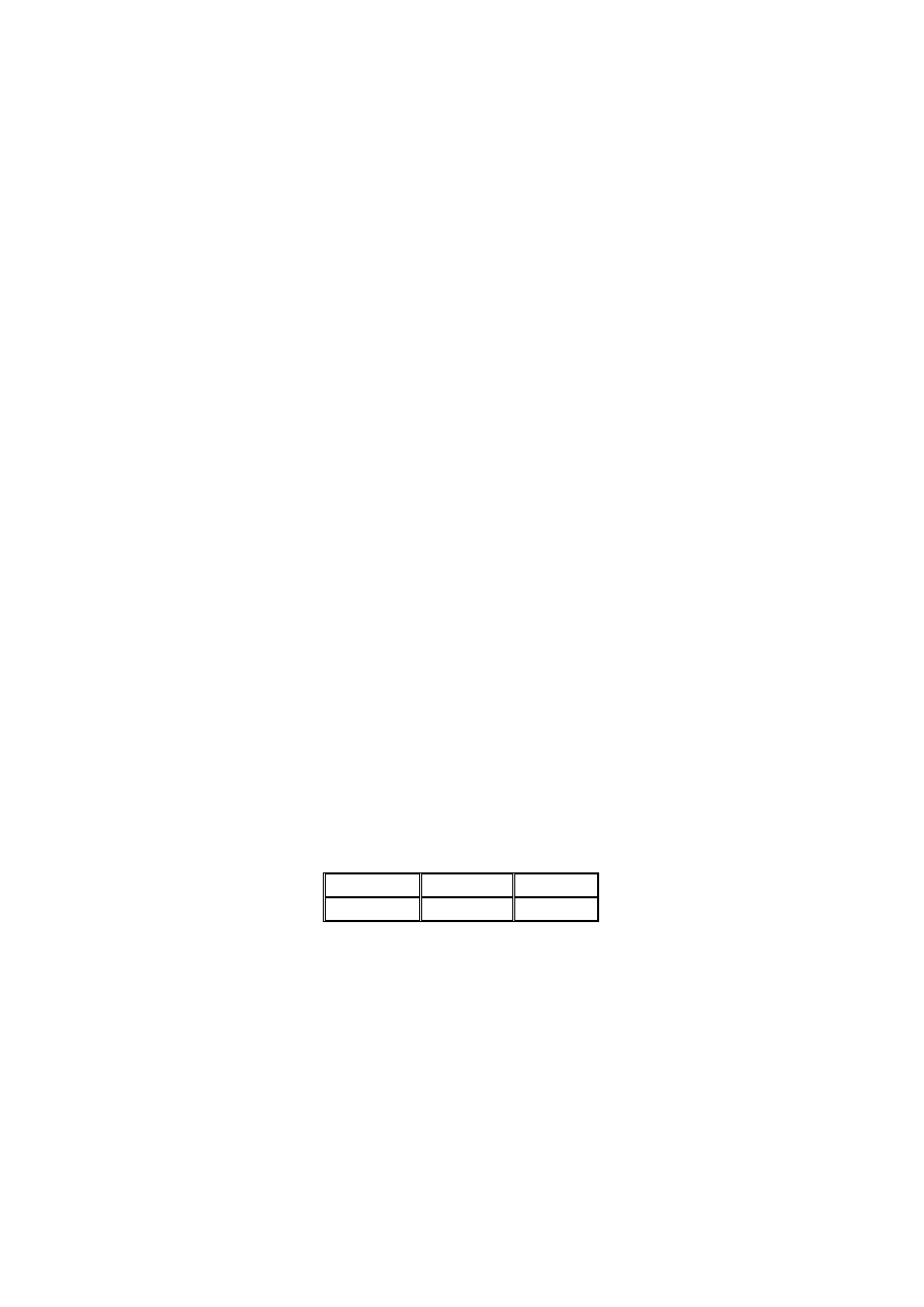
Revised Final PT Draft (pre Stage 49)
Page 49
Draft July 2003
prEN 1998-3:200X
B.5.2.3 Repair of Buckled and Fractured Flanges
(1) Buckled and/or fractured flanges should be either strengthened or replaced with new
plates.
(2) Buckled bottom and/or top flanges should be repaired through full height web
stiffeners on both sides of the beam webs, heat straightening or cutting of the buckled
flange and replacement with similar plate.
(3) Web stiffeners should be located at the edge and centre of the buckled flange,
respectively; the stiffener thickness should be equal to the beam web to achieve
satisfactory performance at SD and NC.
(4) New plates should be either welded in the same location as the original flange, i.e.,
welding the plate directly to the beam web, or welded onto the existing flange. In both
cases the added plates should be oriented with the rolling direction in the proper
direction.
(5) Special shoring of the flange plates should be provided during the intervention of
cutting and replacement.
(6) The encasement of steel beams in RC should be preferred to plates welded onto the
flanges in the case of thick plates.
B.5.2.4 Weakening of Beams
(1) Local ductility of steel beams is improved by weakening of the cross section at
desired locations, i.e. shifting the dissipative zones away from the connections.
(2) Reduced beam sections (RBSs) or dog-bones behave like a fuse thus protecting
beam-to-column connections against early fracture. The minimum rotations that can be
achieved at each LS are provided in Table B.3.
Table B.3. - Rotations of RBSs (in radians).
DL
SD
NC
0.010
0.025
0.040
(3) To achieve the rotations given in Table B.3 the design of RBS beams should be
carried out through the procedure outlined hereafter:
i. Compute the length and position of the flange reduction by defining a and b
(Figure B.1) as follows:
f
b
0.60
a
=
(B.7.1)
b
d
0.75
b
=
(B.7.2)
where b
f
and d
b
are flange width and beam depth, respectively.
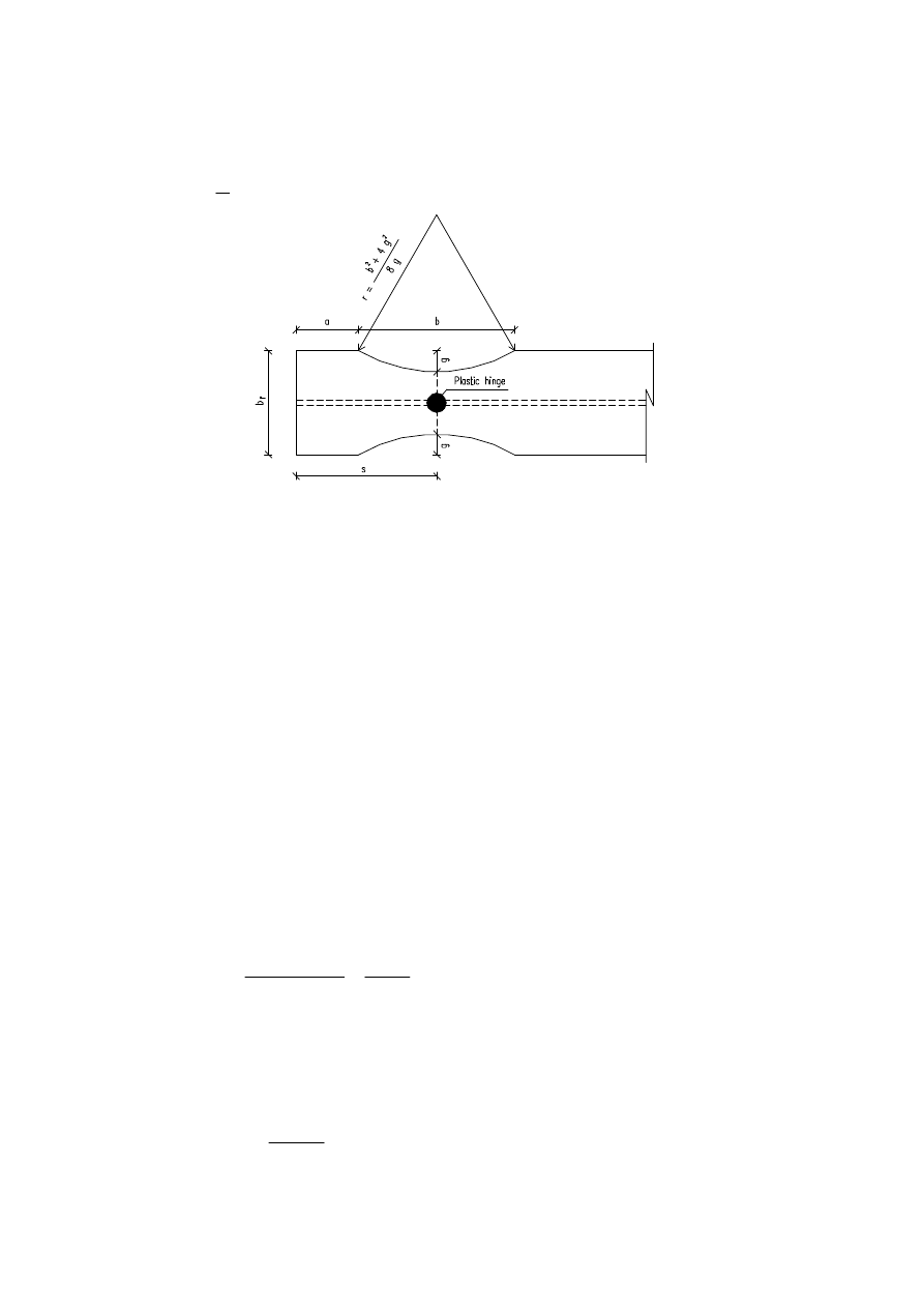
Revised Final PT Draft (pre Stage 49)
Page 50
Draft July 2003
prEN 1998-3:200X
ii. Compute the distance of the plastic hinge formation (s) from the beam edge
given by:
2
b
a
s
+
=
(B.8)
Figure B.1. - Geometry of radius cut for RBS.
iii. Compute the depth of the flange cut (g); it should be not greater than 0.25
⋅
b
f
.
However, as first trial assume:
f
b
0.20
g
⋅
=
(B.9)
iv. Compute the plastic module (Z
RBS
) and hence the plastic module (M
pl,Rd,RBS
) of
the RBS:
y
RBS
RBS
Rd,
pl,
f
Z
M
⋅
=
(B.10.1)
The plastic module (Z
RBS
) of the RBS is
(
)
f
b
f
b
RBS
t
d
t
g
2
Z
Z
−
⋅
⋅
⋅
−
=
(B.10.2)
where Z
b
is the plastic module of the beam.
v. Compute the plastic shear (V
pl, Rd
) in the section of plastic hinge formation via
the free body equilibrium of the beam part (L’) between hinges (Figure B.):
2
L'
w
L'
M
2
V
RBS
Rd,
pl,
Rd
pl,
⋅
+
⋅
=
(B.11)
where w are the uniform beam gravity loads. Additional point loads along the beam
span, if any, should be however accounted for.
vi. Compute the beam plastic moment (M
pl,Rd,b
) as follows:
y
ov
b
y
y
u
b
Rd,
pl,
f
ã
Z
f
2
f
f
M
⋅
⋅
⋅
⋅
+
=
(B.12)
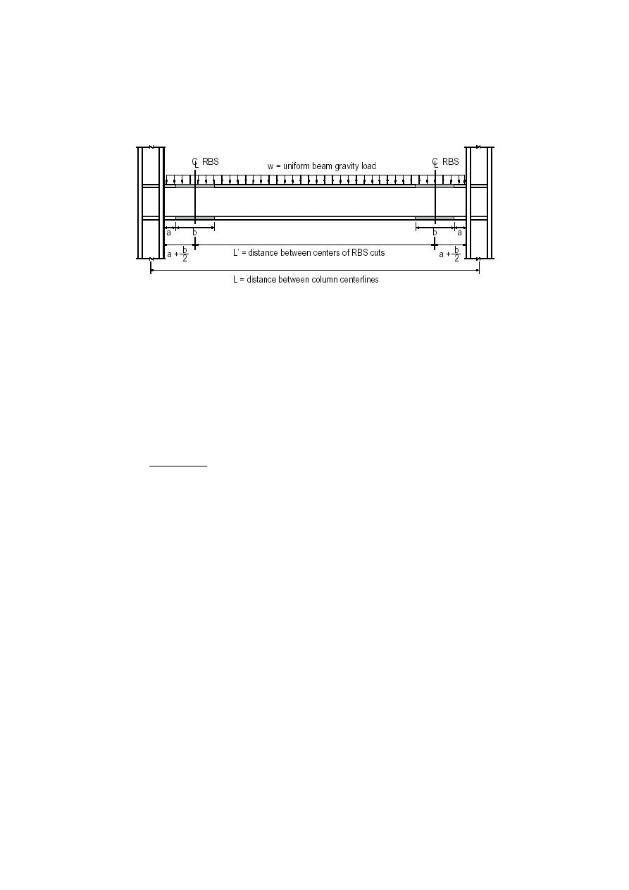
Revised Final PT Draft (pre Stage 49)
Page 51
Draft July 2003
prEN 1998-3:200X
vii. Check that the bending moment M
cf,Sd
is less than M
pl,Rd,b
; otherwise increase
the cut-depth c and repeat steps (iv) to (vi). The length g should be chosen such
that the maximum moment at the column flange is about 85% to 100% of the
beam expected plastic moment.
Figure B.2. -Typical sub-frame assembly with RBS.
viii. Check width-to-thickness ratios to prevent local buckling. The flange width
should be measured at the ends of the centre of 2/3 of the reduced section of
the beam unless gravity loads are large enough to shift the hinge point
significantly from the centre point of the reduced section.
ix. Compute the radius (r) of cuts in both top and bottom flanges over the length b
of the beam:
g
8
g
4
b
r
2
2
⋅
⋅
+
=
(B.13)
x. Check that the fabrication process ensures the adequate surface roughness, i.e.
13
µ
m; for the finished cuts and grind marks are not present.
B.5.2.5 Composite Elements
(1)
The capacity of composite beams should account for the degree of shear
connection between the steel member and the slab.
(2)
Shear connectors between steel beams and composite slabs should not be used
within dissipative zones. They should be removed if present in existing buildings.
(3)
Studs should be attached to flanges arc-spot welds but without full penetration
of the flange. Either shot or screwed attachments should be avoided.
(4)
It should be checked that the maximum tensile strains due to the presence of
composite slabs do not provoke flange tearing.
(5)
Encased beams should have stiffeners and stirrups.

Revised Final PT Draft (pre Stage 49)
Page 52
Draft July 2003
prEN 1998-3:200X
B.5.3 Columns
B.5.3.1 Stability Deficiencies
(1)
Local buckling checks for hollow sections should employ a reduction of 20% for
the wall slenderness with regard to the limits in EN 1993-1 and EN 1998-1 to achieve
satisfactory performance at DL and SD.
(2)
Steel plates should be welded to flange and/or webs to reduce the slenderness
ratios.
(3)
Wall slenderness of hollow section should be reduced by welding external steel
plates.
(4)
Lateral support should be provided for both flanges. Stiffeners should have
minimum strength at DL equal to:
f
f
y
ov
t
b
f
ã
0.06
⋅
⋅
⋅
⋅
(B.14)
where b
f
and t
f
the flange width and thickness, respectively.
B.5.3.2 Resistance Deficiencies
(1)
Steel plates should be welded parallel to the flanges and/or webs for H-sections
and parallel to the wall thickness for hollow sections.
(2)
Structural steel columns should be encased in RC.
(3)
The level of axial load should be reduced to 1/3 of the squash load at DL and 1/2
at SD and NC.
B.5.3.3 Repair of Buckled and Fractured Flanges and Splices Fractures
(1) Buckled and/or fractured flanges and splice fractures should be either strengthened
or replaced with new plates.
(2) Buckled and fractured flanges should be repaired through removal and replacement
of the buckled plate flange with similar plate or flame straightening.
(3) Splice fractures should be repaired adding external plates on the column flanges via
complete penetration groove welds. Thus the damaged part should be removed and
replaced with sound material. The thickness of added plates should be equal to the
existing ones and the replacement material should be aligned with the rolling direction
matching that of the column.
(4) Small holes should be drilled at the edge of the crack to prevent its propagation.
(5) Magnetic particle or liquid dye penetrant tests should be used to ascertain that
within a circular neighbour of the cracks, with radius of about 150mm, there are no
defects and/or discontinuities.

Revised Final PT Draft (pre Stage 49)
Page 53
Draft July 2003
prEN 1998-3:200X
B.5.3.4 Requirements for Column Splices
(1) Splices should be located in the middle third of the column clear height. They
should be designed to develop nominal strength not less than expected shear
strength of the smaller connected member and 50% of the expected flexural strength
of the smaller connected section. Thus, each flange of welded column splices should
satisfy at DL the following:
fl
fl
y,
ov
pl
y,
pl
A
f
ã
0.50
f
A
⋅
⋅
⋅
≥
⋅
(B.15)
where A
pl
and f
y,pl
are the area and the nominal yield strength of each flange. The
second member of eqn.(B.15) represents the expected yield strength of the column
material. A
fl
is the flange area of the smaller column connected.
B.5.3.5 Column Panel Zone
(1) Column panel zone should remain elastic at DL.
(2) The thickness (t
w
) of the column panel should comply with the following empirical
equation to prevent premature local buckling under large inelastic shear
deformations:
90
w
d
t
z
z
w
+
≤
(B.16)
where d
z
and w
z
are respectively the panel-zone depth between continuity plates
and panel-zone width between column flanges. The thickness of the column web
includes the doubler plate, if any; plug welds between web and added plate should
be used.
(3) Steel plate parallel to the web and welded at the tip of flanges (doubler plate) may be
used to stiffen and strengthen the column web.
(4) Transverse stiffeners should be welded onto the column web at the same distance of
beam flanges in beam-to-column connections.
(5) The thickness of continuity plates should be equal to that of beam flanges and
should be placed symmetrically on both sides of the column web. This detail
ensures adequate performance at all limit states.
B.5.3.6 Composite Elements
(1)
RC encasement can be used to enhance the stiffness, strength and ductility of
steel columns.
(2)
To achieve effective composite action shear stresses should be transferred
between the structural steel and reinforced concrete hence shear connectors should be
placed along the column.

Revised Final PT Draft (pre Stage 49)
Page 54
Draft July 2003
prEN 1998-3:200X
(3)
To prevent shear bond failure the steel flange ratio (b
f
/B) at DL should be less
than the critical steel flange ratio defined as follows:
⋅
⋅
+
⋅
⋅
+
⋅
⋅
−
=
ywh
w
c
g
d
cr
f
f
ñ
0.20
f
A
N
0.073
1
0.17
0.35
1
B
b
(B.17)
in which N
d
is the design axial, A
g
the gross area of the section, f
c
is the concrete
compressive strength and
ρ
w
and f
ywh
are respectively the ratio and yield strength of
transverse reinforcement. B is the width of the composite section, while b
f
is the flange
width.
B.5.4 Bracings
B.5.4.1 Stability Deficiencies
(1)
Local buckling checks for hollow sections should employ a reduction of 20% for
the wall slenderness with regard to the limits in EN 1993-1 and EN 1998-1 to achieve
satisfactory performance at DL and SD.
(2)
Steel plates should be welded parallel to the flanges and/or webs for H-sections
and parallel to the wall thickness for hollow sections.
(3)
Encasement of steel bracings should be performed in compliance with
requirements in EN 1998-1.
(4)
Lateral stiffness of diagonal braces can be improved by increasing the stiffness
of the end connections.
(5)
V and inverted V are less good than X bracings. K bracings should not be used.
(6)
Close spacing of stitches is effective to improve the post-buckling response of
braces, particularly for double-angle and double-channel braces. If stitch plates are
already in place new plates should be welded and/or existing stitch connections should
be strengthened.
B.5.4.2 Resistance Deficiencies
(1)
The level of axial load should be not greater than 80% of the squash load at DL.
(2)
Bracing in concentrically braced frames should have in compression at least 50%
of the tensile capacity at DL and SD.
B.5.4.3 Composite Elements
(1)
The encasement of steel bracings in RC increases their stiffness, strength and
ductility. Partial or full RC encasements of steel braces can be used for H-sections.

Revised Final PT Draft (pre Stage 49)
Page 55
Draft July 2003
prEN 1998-3:200X
(2)
Encased bracings should have stiffeners and stirrups. The transverse
confinement of RC should be spread uniformly along the brace and should comply with
details for class ductility M as in EN 1992-1.
(3)
Composite bracings in tension should be designed on the basis of the structural
steel section alone.
B.5.4.4 Unbonded Bracings
(1) Braces may be stiffened either in RC walls or concrete-filled tube (unbonded
braces).
(2) The brace should be coated with debonding material in order to reduce the bond
stress between the steel component and the RC panels or the infilling concrete.
(3) Low yield strength steels should be used for the steel bracing, while steel-fibre
reinforced concrete may be used as unbonding material.
(4) The design of braces stiffened in RC walls at DL should comply the following:
l
a
1.30
m
n
1
1
B
y
B
E
⋅
>
⋅
−
(B.18.1)
in which a and l are the initial imperfection and the length of the steel brace,
respectively.
(5) The non-dimensional strength (
B
y
m
) and stiffness (
B
E
n
) of the RC panel parameters
are given by:
l
N
M
m
y
B
y
B
y
⋅
=
(B.18.2)
y
B
E
B
E
N
N
n
=
(B.18.3)
where:
6
f
T
B
5
M
ct
2
C
S
B
y
⋅
⋅
⋅
=
(B.18.4)
2
3
C
B
S
2
B
E
l
12
T
E
B
ð
5
N
⋅
⋅
⋅
⋅
⋅
=
(B.18.5)
where E
B
is the elastic modulus of the RC panel, B
S
the width of the steel flat-bar
brace, T
C
is the thickness of the panel and f
ct
the tensile strength of the concrete. N
y
is the yield strength of the steel brace.

Revised Final PT Draft (pre Stage 49)
Page 56
Draft July 2003
prEN 1998-3:200X
(6) Edge reinforcement of the RC panel should be adequately anchored to prevent the
punching shear.
(7) Infilled concrete tube with debonding material should be adequate to prevent
buckling of steel bracing.
B.6 Connection Retrofitting
(1) Connections of retrofitted members should be checked considering the resistance of
the retrofitted members, which may be higher than the original ones (before retrofitting).
(2) The provided retrofitting strategies can be applied to steel and composite moment
and braced frames.
B.6.1 Beam-to-Column Connections
(1) The retrofitting schemes shift the beam plastic hinge away from the column face.
(2) Beam-to-column connections may be retrofitted through weld replacement,
weakening strategy or strengthening strategy.
(3) The column-beam moment ratio (CBMR) should be computed as follows if not
specified otherwise:
1.30
M
M
CBMR
b
Rd,
j,
c
Rd,
≥
=
∑
∑
(B.19.1)
where:
i
c
c
yc
c
c
Rd,
i,
A
N
f
Z
M
∑
∑
−
⋅
=
(B.19.2)
where Z
c
is the plastic modulus of the column section, evaluated on the basis of
actual geometrical properties, if available, rather than from standard tables. The
plastic modulus should account for haunches, if any. N
c
and A
c
are respectively the
axial load and the area of the column section. f
yc
is the nominal yield strength of the
columns.
∑
b
Rd,
j,
M
is the sum of flexural strengths at plastic hinge locations to the column
centreline. It should be computed as follows:
(
)
j
Sd
cc,
yb
ov
b
be
Rd,
j,
M
f
ã
Z
M
∑
∑
+
⋅
⋅
=
(B.19.3)
in which Z
b
is the plastic modulus of the beam section at the potential plastic hinge
location; it should be computed on the basis of the actual geometry. The quantity
M
cc,Sd
accounts for the additional moment at the column centreline due to the
eccentricity of shear at the plastic hinge within the beam.

Revised Final PT Draft (pre Stage 49)
Page 57
Draft July 2003
prEN 1998-3:200X
(4) Properties of upgraded connections along with requirements for beams and columns
are provided in Table 4.
B.6.1.1 Weld Replacement
(1)
The existing filler material should be gouged out and replaced it with sound one.
(2)
Backing bars should be removed after welding because they may cause initiation
of cracks.
(3)
Transverse stiffeners at the top and bottom of the panel zone should be used to
strengthen and stiffen the column panel. The thickness should be not less than the
thickness of beam flanges.
(4)
Transverse and web stiffeners should be welded to column flanges and web via
complete joint penetration welds.
Table B.4. - Properties of upgraded connections.
IWUFCs
WBHCs
WTBHCs
WCPFCs
RBSCs
Hinge location
(from column
centerline)
(
) (
)
2
d
2
d
b
c
+
(
)
h
c
l
2
d
+
(
)
h
c
l
2
d
+
(
)
cp
c
l
2
d
+
(
) ( )
a
2
b
2
d
c
+
+
Beam depth
(mm)
1000
≤
1000
≤
1000
≤
1000
≤
1000
≤
Beam span-to-
depth ratio
7
≥
7
≥
7
≥
7
≥
7
≥
Beam flange
thickness
(mm)
25
≤
25
≤
25
≤
25
≤
44
≤
Column depth
(mm)
any
570
≤
570
≤
570
≤
570
≤
Rotation @
DL (radians)
0.013
0.018
0.018
0.018
0.020
Rotation @
SD (radians)
0.030
0.038
0.038
0.060
0.030
Rotation @
NC (radians)
0.050
0.054
0.052
0.060
0.045
Keys:
IWUFCs = Improved welded unreinforced flange connections.
WBHCs = Welded bottom haunch connections.
WTBHCs = Welded top and bottom haunch connections.
WCPFCs = Welded cover plate flange connections.
RBSCs = Reduced beam section connections.
DL = Limit state of damage limitation.
SD = Limit state of severe damage.

Revised Final PT Draft (pre Stage 49)
Page 58
Draft July 2003
prEN 1998-3:200X
NC = Limit state of near collapse.
d
c
= Column depth.
d
b
= Beam depth.
l
h
= Haunch length.
l
cp
= Cover plate length.
a = Distance of the radius cut from the beam edge.
b = Length of the radius-cut.
B.6.1.2 Weakening Strategies
B.6.1.2.1 Connections with RBS Beams
(1) Plastic hinges are forced to occur within the reduced sections, thus reducing the
likelihood of fracture occurring at the beam flange welds and surrounding heat affected
zones (HAZs).
(2) Welded webs should be used to joint the beam to the column flange. Alternatively,
shear tabs should be welded to the column flange face and beam web. The tab length
should be equal to the distance between the weld access holes with an offset of 5 mm; a
minimum thickness of 10 mm is required. They should be either cut square or tapered
edges (tapering corner about 15°) and placed on both sides of the beam web.
(1) The welds should be groove welds or fillet for the column flange and fillet welds for
the beam web. Bolting of the shear tab to the beam web may be used if more
convenient economically.
(2) Shear studs should not be placed within the RBS zones.
(3) The design procedure for RBS connections is outlined below:
i. Use RBS beams designed in compliance with the procedure in B.5.2.4. However it
is advised to compute the beam plastic moment (M
pl,Rd,b
) as follows:
⋅
−
−
−
⋅
⋅
⋅
⋅
+
=
b
2
d
L
d
L
f
ã
Z
f
2
f
f
M
c
c
y
ov
RBS
y
u
y
b
Rd,
pl,
(B.20.1)
in which L is the distance between column centrelines, d
c
is the column depth and
b is the length of RBS.
ii. Hence, the beam expected shear (V
pl,Rd,b
) is given by:
2
L'
w
L'
M
2
V
b
Rd,
pl,
b
Rd,
pl,
⋅
+
⋅
=
(B.20.2)
in which w is the uniform load along the beam span (L’) between plastic hinges:
b
2
d
L
L'
c
⋅
−
−
=
(B.20.3)

Revised Final PT Draft (pre Stage 49)
Page 59
Draft July 2003
prEN 1998-3:200X
Additional point vertical loads, if any, should be included in eqn.(B.20.2).
iii. Check the web connection, e.g. welded shear tab, by using the expected shear
V
pl,Rd,b
as given in eqn.(B.20.2).
iv. Check the strong column-weak beam requirement via the CBMRs, defined as:
(
)
1.20
f
2
f
f
b
2
d
L
d
L
f
ã
Z
f
f
Z
CBMR
b
y,
b
y,
b
u,
c
c
b
y,
ov
b
a
yc
c
≥
⋅
+
⋅
⋅
−
−
−
⋅
⋅
⋅
−
=
∑
∑
(B.21)
with Z
b
and Z
c
the plastic moduli of the beams and columns, respectively; f
a
is the
design stress in the columns.
v. Compute the thickness of the continuity plates to stiffen the column web at top
and bottom beam flange. Such thickness should be equal to that of the beam
flange.
vi. Check the strength and stiffness of the panel zone. It should be assumed that the
panel remains elastic thus:
−
⋅
⋅
−
−
−
⋅
⋅
+
⋅
⋅
⋅
≥
⋅
⋅
∑
H
d
H
b
2
d
L
d
L
d
f
2
f
f
f
ã
Z
3
f
t
d
b
c
c
b
b
y,
b
y,
b
u,
b
y,
ov
b
wc
y,
wc
c
(B.22)
where d
c
and t
wc
are the depth and the thickness of the column web, f
y,wc
is the
minimum specified yield strength and H is the frame story height. The column
web thickness t
wc
should include the doubler plates, if any.
vii. Compute and detail the welds between joined parts.
B.6.1.2.2 Semi-rigid Connections
(1)
Semi-rigid and/or partial strength connections, either steel or composite, may be
used to achieve large plastic deformations without fracturing.
(2)
Full interaction shear studs should be welded onto the beam top flange.
(3)
The design of semi-rigid connections may be carried out by assuming that the
shear is assigned to the components on the web and the bending to the beam bottom
flange and slab reinforcement, if any.
B.6.1.3 Strengthening Strategies
B.6.1.3.1 Haunched Connections
(1) Beam-to-column connections may be strengthened by placing haunches either
at bottom or at top and bottom of the beam flanges, thus the dissipative zone is forced

Revised Final PT Draft (pre Stage 49)
Page 60
Draft July 2003
prEN 1998-3:200X
at the end of the haunch. However, the former details are more convenient because
bottom flanges are generally far more accessible than top ones and the composite slab
does not have to be removed.
(2) Triangular T-shaped haunches are the most effective among the different types
of haunch details. Their depth should be ¼ of the beam depth for bottom haunches.
Haunches should be 1/3 of the beam height for connections with top and bottom
haunches.
(3) Transverse stiffeners should be used to strengthen the column panel and should
be placed at top and bottom beam flanges.
(4) Steel plates should be used at the haunch edges to stiffen the column web and
beam web, respectively.
(5) The vertical stiffeners for the beam web should be full depth and welded on both
sides of the web. The thickness should be proportioned to withstand the vertical
component of the force at that location. However, they should be not less thick than
beam flanges. It is required to perform local checks for flange bending, web yielding and
web crippling in compliance with EN 1993-1.
(6) Haunches should be welded via complete joint penetration welds to both
column and beam flanges.
(7) Bolted shear tabs may be left in place if existing. Alternatively, shear tabs may
be used if required for either structural or erection purposes.
(8) The step-by-step design procedure for haunched connections is summarized
below.
i. Select preliminary haunch dimensions on the basis of slenderness limitation for
the haunch web. The following relationship may be used as first trial for the
haunch length (a) and its slope (
θ
):
b
d
0.55
a
⋅
=
(B.23.1)
°
=
30
è
(B.23.2)
where d
b
is the beam depth. The haunch depth b should be compatible with
architectural restraints, e.g. ceilings and non structural elements. The haunch depth
is given by b = a
⋅
tan
θ
.
ii. Compute the beam plastic moment (M
pl,Rd,b
) at the haunch tip
y
ov
b
y
u
y
b
Rd,
pl,
f
ã
Z
f
2
f
f
M
⋅
⋅
⋅
⋅
+
=
(B.24)
with Z
b
the plastic modulus of the beam.

Revised Final PT Draft (pre Stage 49)
Page 61
Draft July 2003
prEN 1998-3:200X
iii. Compute the beam plastic shear (V
pl,Rd,b
) from force equilibrium of the beam span
(L’) between plastic hinges:
2
L'
w
L'
M
2
V
b
Rd,
pl,
b
Rd,
pl,
⋅
+
⋅
=
(B.25)
in which w is the uniform load between L`; additional point vertical loads, if any,
should be included in eqn.(B.25).
iv. Check the strong column-weak beam requirement via the CBMRs, defined as:
(
)
1.20
M
f
f
Z
CBMR
c
a
yc
c
≥
−
⋅
=
∑
∑
(B.26.1)
in which Z
c
is the plastic section modulus of the columns, f
yc
is the column yield
strength; f
a
is the axial stress in the columns due to the design loads. M
c
is the sum
of column moments at the top and bottom ends of the enlarged panel zone
resulting from the development of the beam moment M
pld
within each beam of the
connection. It is given as follows:
(
)
[
]
−
⋅
−
⋅
+
=
∑
c
b
c
b
Rd,
pl,
b
Rd,
pl,
c
H
d
H
L'
L
V
2M
M
(B.26.2)
where L is the distance between the column centrelines,
b
d is the depth of the
beam including the haunch and H
c
is the story height of the frame.
v. Compute the actual value of the non-dimensionalised parameter
β
given by:
⋅
+
⋅
+
⋅
+
⋅
⋅
+
⋅
⋅
⋅
+
⋅
⋅
+
⋅
⋅
+
⋅
⋅
⋅
=
è
cos
A
I
12
A
I
12
b
4
d
b
6
d
3
b
a
4
L'
b
3
d
a
3
d
L'
3
a
b
â
3
hf
b
b
b
2
2
(B.27)
where A
hf
is the area of the haunch flange.
vi. Compute the value of the non-dimensionalised parameter
β
min
given by:
(
)
−
⋅
⋅
+
⋅
⋅
−
⋅
+
=
b
b
2
b
b
Rd,
pl,
x
b
Rd,
pl,
uw
x
b
Rd,
pl,
b
Rd,
pl,
min
A
I
4
d
tanè
I
V
S
a
V
f
0.80
S
a
V
M
â
(B.28)
where f
uw
is the tensile strength of the welds, S
x
is the beam elastic (major)
modulus, d is the beam depth. A
b
and I
b
are respectively the area and moment of
inertia of the beam.
vii. Compare the non-dimensionalised
β
-values, as calculated above.
Revised Final PT Draft (pre Stage 49)
Page 62
Draft July 2003
prEN 1998-3:200X
If
min
β
≥
β
the haunch dimensions are adequate and further local checks as should
be performed. By contrast,
min
β
<
β
requires an increase of the haunch flange
stiffness. Stiffer flanges may be obtained by either increasing the area A
hf
or
modifying the haunch geometry.
viii. Perform strength and stability checks for the haunch flange:
(strength)
sinè
f
ã
V
â
A
hf
y,
ov
b
Rd,
pl,
hf
⋅
⋅
⋅
≥
(B.29.1)
(stability)
y
hf
hf
f
235
10
t
b
⋅
≤
(B.29.2)
where f
y,hf
is the yield strength of the haunch flange; b
hf
and t
hw
are the flange
outstanding and flange thickness of the haunch, respectively.
ix. Perform strength and stability checks for the haunch web:
(strength)
( )
( )
3
f
ã
3
a
â
1
2
d
è
tan
â
2
L`
I
õ
1
2
V
a
ô
hw
y,
ov
b
b
Rd,
pl,
hw
⋅
≤
⋅
−
+
−
⋅
+
⋅
⋅
=
(B.30.1)
(stability)
y
hw
f
235
33
t
è
sin
a
2
⋅
≤
⋅
⋅
(B.30.2)
where f
y,hw
is the yield strength of the haunch web, t
hw
is the web thickness;
ν
is
the Poisson’s ratio of steel.
x. Check the shear capacity of the beam web. The shear in the beam web is given by:
( )
b
Rd,
pl,
bw
Rd,
pl,
V
â
1
V
⋅
−
=
(B.31)
Web yielding and web crippling should also be checked on the basis of the shear
in eqn.(B.31) at DL.
xi. Design transverse and beam web stiffeners. Their dimensions should be adequate
to withstand the concentrated force
β ⋅
V
pl,Rd,b
/ tan
θ
. Web stiffeners should
possess sufficient strength to resist the concentrated load
β
⋅
V
pl,Rd,b
along with the
beam web. Width-to-thickness ratios for stiffeners should be limited to 15 to
prevent local buckling.
xii. Perform weld detailing by using complete joint penetration welds to connect each
stiffener to the beam flange. Two-sided 8 mm fillet welds are adequate to connect
the stiffeners to the beam web.

Revised Final PT Draft (pre Stage 49)
Page 63
Draft July 2003
prEN 1998-3:200X
B.6.1.3.2 Cover Plate Connections
(1) Cover plate connections reduce the stress at the beam flange welds and force the
yielding in the beam at the end of the cover plates.
(2) Reinforcing plates may be used either at bottom or top and bottom beam
flanges.
(3) Reinforcing steel plates should have rectangular shapes and be fabricated with
rolling directions parallel to the beam.
(4) Connections with welded beam webs and relatively thin and short cover plates
should be preferred to bolted web and heavy and long plates.
(5) Long plates should not be used for beams with short spans and high moment
gradient.
(6) The step-by-step design procedure for cover plate connections is summarized
below.
i. Select cover plate dimensions on the basis of the beam size:
bf
cp
b
b
=
(B.32.1)
bf
cp
t
1.20
t
⋅
=
(B.32.2)
2
d
l
b
cp
=
(B.32.3)
where b
cp
is the width, t
cp
the thickness and l
cp
the length of the cover plate.
ii. Compute the beam plastic moment (M
pl,Rd,b
) at the end of the cover plates as in
eqn. (B.4).
iii. Compute the beam plastic shear (V
pl,Rd,b
) from force equilibrium of the beam span
(L’) between plastic hinges:
2
L'
w
L'
M
2
V
b
Rd,
pl,
b
Rd,
pl,
⋅
+
⋅
=
(B.33.1)
in which w is the uniform load between L`; additional point vertical loads, if any,
should be included in eqn. (B.33.1). The distance L` between the plastic hinges in
the beam is as follows:
cp
c
l
2
d
L
L`
⋅
−
−
=
(B.33.2)
iv. Compute the moment at the column flange (M
cf,Sd
):
cp
b
Rd,
pl,
b
Rd,
pl,
Sd
cf,
l
V
M
M
⋅
+
=
(B.34)

Revised Final PT Draft (pre Stage 49)
Page 64
Draft July 2003
prEN 1998-3:200X
v. Check that the area of cover plates (A
cp
) satisfies the following requirement:
(
)
[
]
Sd
cf,
y
ov
cp
b
cp
b
M
f
ã
t
d
A
Z
≥
⋅
⋅
+
⋅
+
(B.35)
vi. Check the strong column-weak beam requirement via the CBMRs, defined as:
(
)
1.20
f
2
f
f
L
2
d
L
d
L
f
ã
Z
f
f
Z
CBMR
b
y,
b
y,
b
u,
cp
c
c
b
y,
ov
b
a
yc
c
≥
⋅
+
⋅
⋅
−
−
−
⋅
⋅
⋅
−
=
∑
∑
(B.36)
with Z
b
and Z
c
the plastic moduli of the beams and columns, respectively.
vii. Compute the thickness of the continuity plates to stiffen the column web at top
and bottom beam flange. Such thickness should be equal to that of the beam
flange.
viii. Check the strength and stiffness of the panel zone. It should be assumed that the
panel remains elastic thus:
−
⋅
−
⋅
≥
⋅
⋅
∑
H
d
H
d
L
L
d
M
3
f
t
d
b
c
b
f
wc
y,
wc
c
(B.37)
where d
c
and t
wc
are the depth and the thickness of the column web, f
y,wc
is the
minimum specified yield strength and H is the frame story height. The column
web thickness t
wc
should include the doubler plates, if any.
ix. Compute and detail the welds between joined parts, i.e. beam to cover plates,
column to cover plates and beam to column. Weld overlays should employ the
same electrodes or at least with similar mechanical properties.
B.6.2 Bracing and Link Connections
(1) The design of bracing and link connections should account for the effect of the
brace member cyclic post-buckling behaviour.
(2) Fixed end connections should be preferred to those that are pinned.
(3) To improve out-of-plane stability of the bracing connection the continuity
between beams and columns should not be interrupted.
(4) The intersection of the brace and the beam centrelines located outside the link
should be avoided.
(5) Connections between the diagonal brace and the beam should have centrelines
intersecting either within the length of the link or at its end.
(6) For link-to-column connections at column flange face bearing plates should be
used between the beam flange plates.

Revised Final PT Draft (pre Stage 49)
Page 65
Draft July 2003
prEN 1998-3:200X
(7) The retrofitting of beam-to-column connections may vary the link length.
Therefore, it should be checked after the repairing strategy is adopted.
(8) Links connected to the column should be short.
(9) Welded connections of the link to the column weak-axis should be avoided.

Revised Final PT Draft (pre Stage 49)
Page 66
Draft July 2003
prEN 1998-3:200X
ANNEX C (INFORMATIVE)
C MASONRY STRUCTURES
C.1 Scope
(1)
This annex contains recommendations for the assessment and the design of
strengthening measures in masonry building structures in seismic regions.
(2)
The recommendations of this section are applicable to concrete or brick masonry
lateral force resisting elements within a building system in un-reinforced, confined and
reinforced masonry.
C.2 Identification of geometry, details and materials
C.2.1 General
(1) The following aspects should be carefully examined:
i. Physical condition of masonry elements and presence of any degradation;
ii. Configuration of masonry elements and their connections, as well as the
continuity of load paths between lateral resisting elements;
iii. Properties of in-place materials of masonry elements and connections;
iv. The presence and attachment of veneers, the presence of nonstructural
components, the distance between partition walls;
v. Information on adjacent buildings potentially interacting with the building
under consideration.
C.2.2 Geometry
(1) The collected data should include the following items:
i. Size and location of all shear walls, including height, length and thickness;
ii. Dimensions of masonry units;
iii. Location and size of wall openings (doors, windows);
iv. Distribution of gravity loads on bearing walls.
C.2.3 Details
(1) The collected data should include the following items:
i. Classification of the walls as un-reinforced, confined, or reinforced;

Revised Final PT Draft (pre Stage 49)
Page 67
Draft July 2003
prEN 1998-3:200X
ii. Presence and quality of mortar;
iii. For reinforced masonry walls, amount of horizontal and vertical
reinforcement;
iv. For multi-leaf masonry (rubble core masonry walls), identification of the
number of leaves, respective distances, and location of ties, when existing;
v. For grouted masonry, evaluation of the type, quality and location of grout
placements;
vi. Determination of the type and condition of the mortar and mortar joints;
Examination of the resistance, erosion and hardness of the mortar;
Identification of defects such as cracks, internal voids, weak components
and deterioration of mortar;
vii. Identification of the type and condition of connections between orthogonal
walls;
viii. Identification of the type and condition of connections between walls and
floors or roofs.
ix. Identification and location of horizontal cracks in bed joints, vertical cracks
in head joints and masonry units, and diagonal cracks near openings;
x. Examination of deviations in verticality of walls and separation of exterior
leaves or other elements as parapets and chimneys;
xi. Identification of local condition of connections between walls and floors or
roofs.
C.2.4 Materials
(1)
Non-destructive testing is permitted to quantify and confirm the uniformity of
construction quality and the presence and degree of deterioration. The following types
of tests may be used:
i. Ultrasonic or mechanical pulse velocity to detect variations in the density
and modulus of masonry materials and to detect the presence of cracks and
discontinuities.
ii. Impact echo test to confirm whether reinforced walls are grouted.
iii. Radiography to confirm location of reinforcing steel.
(2)
Supplementary tests may be performed to enhance the level of confidence in
masonry material properties, or to assess masonry condition. Possible tests are:
i. Schmidt rebound hammer test to evaluate surface hardness of exterior
masonry walls.

Revised Final PT Draft (pre Stage 49)
Page 68
Draft July 2003
prEN 1998-3:200X
ii. Hydraulic flat jack test to measure the in-situ vertical compressive stress
resisted by masonry. This test provides information such as the gravity load
distribution, flexural stresses in out-of-plane walls, and stresses in masonry
veneer walls compressed by surrounding concrete frame.
iii. Diagonal compression test to estimate shear strength and shear modulus of
masonry.
iv. Large-scale destructive tests on particular regions or elements, to increase
the confidence level on overall structural properties or to provide particular
information such as out-of-plane strength, behaviour of connections and
openings, in-plane strength and deformation capacity.
C.3 Methods of analysis
(1)
In setting up the model for the analysis, the stiffness of the walls should be
evaluated considering both flexural and shear flexibility, using cracked stiffness. In the
absence of more accurate evaluations, both contributions to stiffness may be taken as
one-half of their respective uncracked values.
(2)
Masonry spandrels may be introduced in the model as coupling beams between
two wall elements.
C.3.1 Linear methods: Static and Multi-modal
(1)
These methods should be applicable under the following conditions:
i. regular arrangement of lateral load resisting walls in both directions,
ii. continuity of the walls along their height,
iii. the floors should possess enough in-plane stiffness and be safely connected
to the perimeter walls in order to assume rigid distribution of the inertia
forces among the vertical elements,
iv. floors on both sides of a common wall should be at the same height,
v. the ratio between the lateral stiffnesses of the stiffer wall and the weakest
one, evaluated accounting for the presence of openings, should not exceed
2.5,
vi. spandrel elements included in the model should either be made of blocks
adequately interlocked to those of the adjacent walls, or endowed with
connecting ties.
C.3.2 Nonlinear methods: Static and Time-history
(1)
These methods should be applicable when one or more of the above conditions
are not met.

Revised Final PT Draft (pre Stage 49)
Page 69
Draft July 2003
prEN 1998-3:200X
(2)
The static method consists in the application of a set of horizontal forces of
increasing intensity until attainment of the peak resistance of the structure. This is
reached with a stiffness decrease due to progressive damage and failure of the
participating lateral load resisting elements. The load-deformation curve is continued
after the peak, until a 20% reduction of the peak load is attained. The corresponding
displacement is considered as the displacement capacity.
(3)
The ultimate limit state verification of the structure consists in checking that the
displacement capacity, evaluated as indicated above, is larger than the corresponding
displacement induced by the elastic design seismic action.
C.4 Capacity models for assessment
C.4.1 Elements under normal force and bending
C.4.1.1 LS of severe damage (SD)
(1)
The verification of the ultimate shear capacity corresponding to flexural collapse
under an axial load P acting on the wall, should be made comparing the shear demand
on the masonry wall with the capacity given as:
(
)
d
f
H
P
D
V
ν
−
=
15
.
1
1
2
0
where D is the wall depth,
)
(
d
d
f
t
D
P
=
ν
is the normalized axial load (with
m
mk
d
f
f
γ
=
being the masonry design strength, where
mk
f
is the characteristic
compressive strength and
m
γ
is the partial safety factor for masonry), t is the wall
thickness, and
0
H is the distance between the section to be verified and the
contraflexure point.
(2)
The ultimate capacity in terms of drift should be assumed equal to 0.008.
C.4.1.2 LS of near collapse (NC) and of damage limitation (DL)
(1)
The verification against the exceedance of these two LS is not required, unless
these two LS are the only ones to be checked.
C.4.2 Elements under shear force
C.4.2.1 LS of severe damage (SD)
(1)
The verification of the ultimate shear capacity corresponding to shear collapse
under an axial load P acting on the wall, should be made comparing the shear demand
on the masonry wall with the capacity given as:
t
D
f
V
vd
f
′
=

Revised Final PT Draft (pre Stage 49)
Page 70
Draft July 2003
prEN 1998-3:200X
where
m
vk
vd
f
f
γ
=
is the shear design strength accounting for the presence of vertical
load, with
mk
vk
vk
f
t
D
P
f
f
065
.
0
4
.
0
0
≤
′
+
=
, being
0
vk
f
the characteristic shear strength
in the absence of vertical load, and D
′
is the depth of the compressed area of the wall.
(2)
In case the verification of the wall is governed by shear, the ultimate capacity in
terms of drift should be assumed equal to 0.004.
C.4.2.2 LS of near collapse (NC) and of damage limitation (DL)
(1)
The verification against the exceedance of these two LS is not required, unless
these two LS are the only ones to be checked.
C.5 Structural interventions
C.5.1 Repair and strengthening techniques
C.5.1.1 Repair of cracks
(1)
Cracks may be sealed with mortar if the crack width is small (e.g., less than 10
mm), and the thickness of the wall is relatively small.
(2)
If the width of the cracks is small but the thickness of the masonry is
considerable, cement grout injections should be used; where possible, the grout should
be shrinkage-free. Epoxy grouting may be used for fine cracks.
(3)
If the crack are relatively wide (e.g., more than 10 mm), the damaged area should
be reconstructed using elongated (stitching) bricks of stones. Otherwise, dove-tailed
clamps, metal plates or polymer grids should be used to tie together the two faces of the
crack, and the voids should be filled with cement mortar. Voids should be filled with
mortar with appropriate fluidity.
(4)
Where bed-joints are reasonably level, the resistance of a wall against vertical
cracking can be considerably improved by embedding either small diameter stranded
wire ropes or polymeric grid strips in the bed-joints.
(5)
For the repair of large diagonal cracks, vertical concrete ribs may be cast into
irregular chases made in the masonry wall, normally on both sides; ribs should be
reinforced with closed stirrups and longitudinal bars, while stranded wire rope as in (4)
should run across the concrete ribs. Alternatively, enveloping polymeric grids may be
used on one or on both sides of masonry walls combined with appropriate mortar and
plaster.
C.5.1.2 Repair and strengthening of wall intersections
(1)
To improve connection between intersecting walls use should be made of cross-
bonded bricks or stones. The connection may be made more effective in different ways:
i. construction of a reinforced concrete belt,

Revised Final PT Draft (pre Stage 49)
Page 71
Draft July 2003
prEN 1998-3:200X
ii. addition of steel plates in the bed-joints,
iii. insertion of inclined steel bars in drilled holes and grouting thereafter.
C.5.1.3 Strengthening and stiffening of horizontal diaphragms
(1)
Timber floors may be strengthened and stiffened against in-plane distortion by:
i. nailing an additional orthogonal or oblique layer of timber boards onto the
existing ones,
ii. casting a thin layer of concrete reinforced with welded wire mesh. The
concrete layer should have a shear connection with the timber floor, and
should be anchored to the walls,
iii. placing a doubly diagonal mesh of flat steel ties anchored to the beams and
to the perimeter walls.
(2)
Roof trusses should be braced and anchored to the supporting walls.
C.5.1.4 Tie beams
(1)
If existing tie beams between walls and floors are damaged, they should be
appropriately repaired or rebuilt. If they are missing in the original structure, they should
be added.
C.5.1.5 Strengthening of buildings by means of steel ties
(1)
The addition of steel ties (along or transversely to the walls, external or within
holes drilled in the walls) is an efficient means of connecting walls and improving the
overall behavior of a masonry building.
(2)
Pretensioned ties may be used to improve the resistance of the walls against
tensile forces.
C.5.1.6 Strengthening of rubble core masonry walls (multi-leaf walls)
(1)
The rubble core may be strengthened by cement grouting, if the penetration of
the grout is satisfactory. However, if the adhesion of the grout to the rubble is likely to
be poor, grouting should be complemented by insertion of steel bars across the core
conveniently anchored to the walls.
C.5.1.7 Strengthening of walls by means of reinforced concrete jackets or steel
profiles
(1)
The concrete should be applied by the shotcrete method and the jackets should
be reinforced by welded wire mesh or steel bars.

Revised Final PT Draft (pre Stage 49)
Page 72
Draft July 2003
prEN 1998-3:200X
(2)
The jackets may be on both sides of the wall or they may be applied on one part
only. If two layers are placed, they should be connected with transverse ties. Simple
jackets should be connected to the masonry by chases.
(3)
Steel profiles may be used in a similar way, provided they are appropriately
connected to both faces of the wall or on one part only.
C.5.1.8 Strengthening of walls by means of polymer grids jackets
(1)
Polymer grids can be used to strengthen existing and new masonry elements. In
case of existing elements, the grids should be connected to masonry walls from one
sides or both sides and anchored to the perpendicular walls. In case of new elements,
the intervention may involve the additional insertion of grids in the horizontal layers of
mortar between bricks. Plaster covering polymeric grids should be ductile, preferably
lime-cement with fibers infill.
Wyszukiwarka
Podobne podstrony:
Eurocode 8 Part 1 prEN 1998 1 (12 2003)
Eurocode 8 Part 5 prEn 1998 5 (12 2003)
Eurocode 8 Part 1 prEN 1998 1 (12 2003)
Eurocode 8 Part 1 prEN 1998 1 (12 2003)
Eurocode 8 Part 4 prEN 1998 4 2003 (12 2003)
Eurocode 1 Part 1,3 prEN 1991 1 3 2003
Eurocode 1 Part 1,5 prEN 1991 1 5 2003
Eurocode 1 Part 1,7 prEN 1991 1 7 2003
Eurocode 3 Part 1,9 PrEN 1993 1 9 2003
Eurocode 3 Part 1,8 prEN 1993 1 8 2003
Eurocode 3 Part 1,9 PrEN 1993 1 9 2003
Eurocode 3 Part 1,8 prEN 1993 1 8 2003
Eurocode 1 Part 1,6 prEN 1991 1 6 2004
Eurocode 1 Part 2 prEN 1991 2 2002
Eurocode 1 Part 1,2 prEN 1991 1 2 2002
Eurocode 1 Part 1,1 prEN 1991 1 1 2001
więcej podobnych podstron