
EUROPEAN STANDARD
NORME EUROPÉENNE
EUROPÄISCHE NORM
FINAL DRAFT
prEN 1998-1
December 2003
ICS 91.120.20
Will supersede ENV 1998-1-1:1994; ENV 1998-1-2:1994
and ENV 1998-1-3:1995
English version
Eurocode 8: Design of structures for earthquake resistance -
Part 1: General rules, seismic actions and rules for buildings
Eurocode 8: Calcul des structures pour leur résistance aux
séismes - Partie 1: Règles générales, actions sismiques et
règles pour les bâtiments
Eurocode 8: Auslegung von Bauwerken gegen Erdbeben -
Teil 1: Grundlagen, Erdbebeneinwirkungen und Regeln für
Hochbauten
This draft European Standard is submitted to CEN members for formal vote. It has been drawn up by the Technical Committee CEN/TC
250.
If this draft becomes a European Standard, CEN members are bound to comply with the CEN/CENELEC Internal Regulations which
stipulate the conditions for giving this European Standard the status of a national standard without any alteration.
This draft European Standard was established by CEN in three official versions (English, French, German). A version in any other
language made by translation under the responsibility of a CEN member into its own language and notified to the Management Centre has
the same status as the official versions.
CEN members are the national standards bodies of Austria, Belgium, Czech Republic, Denmark, Finland, France, Germany, Greece,
Hungary, Iceland, Ireland, Italy, Luxembourg, Malta, Netherlands, Norway, Portugal, Slovakia, Spain, Sweden, Switzerland and United
Kingdom.
Warning : This document is not a European Standard. It is distributed for review and comments. It is subject to change without notice and
shall not be referred to as a European Standard.
EUROPEAN COMMITTEE FOR STANDARDIZATION
C O M I T É E U R O P É E N D E N O R M A L I S A T I O N
E U R O P Ä I S C H E S K O M I T E E F Ü R N O R M U N G
Management Centre: rue de Stassart, 36 B-1050 Brussels
© 2003 CEN
All rights of exploitation in any form and by any means reserved
worldwide for CEN national Members.
Ref. No. prEN 1998-1:2003 E

prEN 1998-1:2003 (E)
2
Contents Page
FOREWORD..............................................................................................................................................8
1
GENERAL.........................................................................................................................................1
1.1
S
COPE
........................................................................................................................................1
1.1.1
Scope of EN 1998.................................................................................................................1
1.1.2
Scope of EN 1998-1 .............................................................................................................1
1.1.3
Further Parts of EN 1998......................................................................................................2
1.2
N
ORMATIVE
R
EFERENCES
..........................................................................................................2
1.2.1
General reference standards..................................................................................................2
1.2.2
Reference Codes and Standards............................................................................................3
1.3
A
SSUMPTIONS
............................................................................................................................3
1.4
D
ISTINCTION BETWEEN PRINCIPLES AND APPLICATION RULES
...................................................3
1.5
T
ERMS AND DEFINITIONS
...........................................................................................................3
1.5.1
Terms common to all Eurocodes ..........................................................................................3
1.5.2
Further terms used in EN 1998.............................................................................................3
1.6
S
YMBOLS
...................................................................................................................................5
1.6.1
General .................................................................................................................................5
1.6.2
Further symbols used in Sections 2 and 3 of EN 1998-1......................................................5
1.6.3
Further symbols used in Section 4 of EN 1998-1 .................................................................6
1.6.4
Further symbols used in Section 5 of EN 1998-1 .................................................................7
1.6.5
Further symbols used in Section 6 of EN 1998-1 ...............................................................10
1.6.6
Further symbols used in Section 7 of EN 1998-1 ...............................................................11
1.6.7
Further symbols used in Section 8 of EN 1998-1 ...............................................................13
1.6.8
Further symbols used in Section 9 of EN 1998-1 ...............................................................13
1.6.9
Further symbols used in Section 10 of EN 1998-1 .............................................................14
1.7
S.I. U
NITS
................................................................................................................................14
2
PERFORMANCE REQUIREMENTS AND COMPLIANCE CRITERIA ..............................15
2.1
F
UNDAMENTAL REQUIREMENTS
...............................................................................................15
2.2
C
OMPLIANCE
C
RITERIA
............................................................................................................16
2.2.1
General ...............................................................................................................................16
2.2.2
Ultimate limit state .............................................................................................................16
2.2.3
Damage limitation state ......................................................................................................17
2.2.4
Specific measures ...............................................................................................................18
2.2.4.1
Design ..................................................................................................................................... 18
2.2.4.2
Foundations............................................................................................................................. 18
2.2.4.3
Quality system plan................................................................................................................. 18
3
GROUND CONDITIONS AND SEISMIC ACTION..................................................................19
3.1
G
ROUND CONDITIONS
..............................................................................................................19
3.1.2
Identification of ground types.............................................................................................19
3.2
S
EISMIC ACTION
.......................................................................................................................21
3.2.1
Seismic zones .....................................................................................................................21
3.2.2
Basic representation of the seismic action..........................................................................22
3.2.2.1
General.................................................................................................................................... 22
3.2.2.2
Horizontal elastic response spectrum ...................................................................................... 23
3.2.2.3
Vertical elastic response spectrum .......................................................................................... 26
3.2.2.4
Design ground displacement ................................................................................................... 27
3.2.2.5
Design spectrum for elastic analysis ....................................................................................... 27
3.2.3
Alternative representations of the seismic action ...............................................................28
3.2.3.1
Time - history representation .................................................................................................. 28
3.2.3.2
Spatial model of the seismic action ......................................................................................... 29
3.2.4
Combinations of the seismic action with other actions.......................................................30
4
DESIGN OF BUILDINGS .............................................................................................................31
4.1
G
ENERAL
.................................................................................................................................31

prEN 1998-1:2003 (E)
3
4.1.1
Scope ..................................................................................................................................31
4.2
C
HARACTERISTICS OF EARTHQUAKE RESISTANT BUILDINGS
....................................................31
4.2.1
Basic principles of conceptual design.................................................................................31
4.2.1.1
Structural simplicity ................................................................................................................ 31
4.2.1.2
Uniformity, symmetry and redundancy................................................................................... 31
4.2.1.3
Bi-directional resistance and stiffness ..................................................................................... 32
4.2.1.4
Torsional resistance and stiffness............................................................................................ 32
4.2.1.5
Diaphragmatic behaviour at storey level ................................................................................. 32
4.2.1.6
Adequate foundation ............................................................................................................... 33
4.2.2
Primary and secondary seismic members...........................................................................33
4.2.3
Criteria for structural regularity..........................................................................................34
4.2.3.1
General.................................................................................................................................... 34
4.2.3.2
Criteria for regularity in plan................................................................................................... 35
4.2.3.3
Criteria for regularity in elevation........................................................................................... 36
4.2.4
Combination coefficients for variable actions ....................................................................38
4.2.5
Importance classes and importance factors ........................................................................38
4.3
S
TRUCTURAL ANALYSIS
...........................................................................................................39
4.3.1
Modelling ...........................................................................................................................39
4.3.2
Accidental torsional effects ................................................................................................40
4.3.3
Methods of analysis ............................................................................................................40
4.3.3.1
General.................................................................................................................................... 40
4.3.3.2
Lateral force method of analysis ............................................................................................. 42
4.3.3.3
Modal response spectrum analysis .......................................................................................... 45
4.3.3.4
Non-linear methods................................................................................................................. 47
4.3.3.5
Combination of the effects of the components of the seismic action ...................................... 50
4.3.4
Displacement analysis ........................................................................................................52
4.3.5
Non-structural elements......................................................................................................52
4.3.5.1
General.................................................................................................................................... 52
4.3.5.2
Verification ............................................................................................................................. 53
4.3.5.3
Importance factors................................................................................................................... 54
4.3.5.4
Behaviour factors .................................................................................................................... 54
4.3.6
Additional measures for masonry infilled frames...............................................................54
4.3.6.1
General.................................................................................................................................... 54
4.3.6.2
Requirements and criteria........................................................................................................ 55
4.3.6.3
Irregularities due to masonry infills ........................................................................................ 55
4.3.6.4
Damage limitation of infills .................................................................................................... 56
4.4
S
AFETY VERIFICATIONS
...........................................................................................................57
4.4.1
General ...............................................................................................................................57
4.4.2
Ultimate limit state .............................................................................................................57
4.4.2.1
General.................................................................................................................................... 57
4.4.2.2
Resistance condition................................................................................................................ 57
4.4.2.3
Global and local ductility condition ........................................................................................ 58
4.4.2.4
Equilibrium condition ............................................................................................................. 60
4.4.2.5
Resistance of horizontal diaphragms....................................................................................... 60
4.4.2.6
Resistance of foundations........................................................................................................ 60
4.4.2.7
Seismic joint condition............................................................................................................ 61
4.4.3
Damage limitation ..............................................................................................................62
4.4.3.1
General.................................................................................................................................... 62
4.4.3.2
Limitation of interstorey drift.................................................................................................. 62
5
SPECIFIC RULES FOR CONCRETE BUILDINGS .................................................................64
5.1
G
ENERAL
.................................................................................................................................64
5.1.1
Scope ..................................................................................................................................64
5.1.2
Terms and definitions .........................................................................................................64
5.2
D
ESIGN CONCEPTS
...................................................................................................................66
5.2.1
Energy dissipation capacity and ductility classes ...............................................................66
5.2.2
Structural types and behaviour factors................................................................................67
5.2.2.1
Structural types ....................................................................................................................... 67
5.2.2.2
Behaviour factors for horizontal seismic actions..................................................................... 68
5.2.3
Design criteria ....................................................................................................................70
5.2.3.1
General.................................................................................................................................... 70
5.2.3.2
Local resistance condition....................................................................................................... 70
5.2.3.3
Capacity design rule................................................................................................................ 70
5.2.3.4
Local ductility condition ......................................................................................................... 70

prEN 1998-1:2003 (E)
4
5.2.3.5
Structural redundancy ............................................................................................................. 72
5.2.3.6
Secondary seismic members and resistances........................................................................... 72
5.2.3.7
Specific additional measures ................................................................................................... 72
5.2.4
Safety verifications.............................................................................................................73
5.3
D
ESIGN TO
EN 1992-1-1..........................................................................................................73
5.3.1
General ...............................................................................................................................73
5.3.2
Materials .............................................................................................................................74
5.3.3
Behaviour factor .................................................................................................................74
5.4
D
ESIGN FOR
DCM....................................................................................................................74
5.4.1
Geometrical constraints and materials................................................................................74
5.4.1.1
Material requirements ............................................................................................................. 74
5.4.1.2
Geometrical constraints........................................................................................................... 74
5.4.2
Design action effects ..........................................................................................................75
5.4.2.1
General.................................................................................................................................... 75
5.4.2.2
Beams...................................................................................................................................... 75
5.4.2.3
Columns .................................................................................................................................. 77
5.4.2.4
Special provisions for ductile walls......................................................................................... 78
5.4.2.5
Special provisions for large lightly reinforced walls ............................................................... 80
5.4.3
ULS verifications and detailing ..........................................................................................81
5.4.3.1
Beams...................................................................................................................................... 81
5.4.3.2
Columns .................................................................................................................................. 83
5.4.3.3
Beam-column joints ................................................................................................................ 86
5.4.3.4
Ductile Walls........................................................................................................................... 86
5.4.3.5
Large lightly reinforced walls ................................................................................................. 90
5.5
D
ESIGN FOR
DCH ....................................................................................................................92
5.5.1
Geometrical constraints and materials................................................................................92
5.5.1.1
Material requirements ............................................................................................................. 92
5.5.1.2
Geometrical constraints........................................................................................................... 92
5.5.2
Design action effects ..........................................................................................................93
5.5.2.1
Beams...................................................................................................................................... 93
5.5.2.2
Columns .................................................................................................................................. 93
5.5.2.3
Beam-column joints ................................................................................................................ 93
5.5.2.4
Ductile Walls........................................................................................................................... 94
5.5.3
ULS verifications and detailing ..........................................................................................95
5.5.3.1
Beams...................................................................................................................................... 95
5.5.3.2
Columns .................................................................................................................................. 97
5.5.3.3
Beam-column joints ................................................................................................................ 98
5.5.3.4
Ductile Walls......................................................................................................................... 100
5.5.3.5
Coupling elements of coupled walls...................................................................................... 105
5.6
P
ROVISIONS FOR ANCHORAGES AND SPLICES
.........................................................................106
5.6.1
General .............................................................................................................................106
5.6.2
Anchorage of reinforcement .............................................................................................106
5.6.2.1
Columns ................................................................................................................................ 106
5.6.2.2
Beams.................................................................................................................................... 106
5.6.3
Splicing of bars.................................................................................................................108
5.7
D
ESIGN AND DETAILING OF SECONDARY SEISMIC ELEMENTS
.................................................109
5.8
C
ONCRETE FOUNDATION ELEMENTS
......................................................................................109
5.8.1
Scope ................................................................................................................................109
5.8.2
Tie-beams and foundation beams .....................................................................................110
5.8.3
Connections of vertical elements with foundation beams or walls...................................111
5.8.4
Cast-in-place concrete piles and pile caps ........................................................................111
5.9
L
OCAL EFFECTS DUE TO MASONRY OR CONCRETE INFILLS
.....................................................112
5.10
P
ROVISIONS FOR CONCRETE DIAPHRAGMS
.............................................................................113
5.11
P
RECAST CONCRETE STRUCTURES
..........................................................................................113
5.11.1
General.........................................................................................................................113
5.11.1.1
Scope and structural types..................................................................................................... 113
5.11.1.2
Evaluation of precast structures ............................................................................................ 114
5.11.1.3
Design criteria ....................................................................................................................... 115
5.11.1.4
Behaviour factors .................................................................................................................. 116
5.11.1.5
Analysis of transient situation ............................................................................................... 116
5.11.2
Connections of precast elements..................................................................................117
5.11.2.1
General provisions ................................................................................................................ 117
5.11.2.2
Evaluation of the resistance of connections........................................................................... 118
5.11.3
Elements ......................................................................................................................118

prEN 1998-1:2003 (E)
5
5.11.3.1
Beams.................................................................................................................................... 118
5.11.3.2
Columns ................................................................................................................................ 118
5.11.3.3
Beam-column joints .............................................................................................................. 119
5.11.3.4
Precast large-panel walls....................................................................................................... 119
5.11.3.5
Diaphragms ........................................................................................................................... 121
6
SPECIFIC RULES FOR STEEL BUILDINGS .........................................................................123
6.1
G
ENERAL
...............................................................................................................................123
6.1.1
Scope ................................................................................................................................123
6.1.2
Design concepts................................................................................................................123
6.1.3
Safety verifications...........................................................................................................124
6.2
M
ATERIALS
............................................................................................................................124
6.3
S
TRUCTURAL TYPES AND BEHAVIOUR FACTORS
.....................................................................126
6.3.1
Structural types.................................................................................................................126
6.3.2
Behaviour factors..............................................................................................................129
6.4
S
TRUCTURAL ANALYSIS
.........................................................................................................130
6.5
D
ESIGN CRITERIA AND DETAILING RULES FOR DISSIPATIVE STRUCTURAL BEHAVIOUR COMMON
TO ALL STRUCTURAL TYPES
..................................................................................................................130
6.5.1
General .............................................................................................................................130
6.5.2
Design criteria for dissipative structures ..........................................................................130
6.5.3
Design rules for dissipative elements in compression or bending ....................................131
6.5.4
Design rules for parts or elements in tension....................................................................131
6.5.5
Design rules for connections in dissipative zones ............................................................131
6.6
D
ESIGN AND DETAILING RULES FOR MOMENT RESISTING FRAMES
..........................................132
6.6.1
Design criteria ..................................................................................................................132
6.6.2
Beams ...............................................................................................................................132
6.6.3
Columns............................................................................................................................133
6.6.4
Beam to column connections............................................................................................135
6.7
D
ESIGN AND DETAILING RULES FOR FRAMES WITH CONCENTRIC BRACINGS
...........................136
6.7.1
Design criteria ..................................................................................................................136
6.7.2
Analysis ............................................................................................................................137
6.7.3
Diagonal members............................................................................................................138
6.7.4
Beams and columns ..........................................................................................................138
6.8
D
ESIGN AND DETAILING RULES FOR FRAMES WITH ECCENTRIC BRACINGS
.............................139
6.8.1
Design criteria ..................................................................................................................139
6.8.2
Seismic links.....................................................................................................................140
6.8.3
Members not containing seismic links..............................................................................143
6.8.4
Connections of the seismic links ......................................................................................144
6.9
D
ESIGN RULES FOR INVERTED PENDULUM STRUCTURES
........................................................144
6.10
D
ESIGN RULES FOR STEEL STRUCTURES WITH CONCRETE CORES OR CONCRETE WALLS AND FOR
MOMENT RESISTING FRAMES COMBINED WITH CONCENTRIC BRACINGS OR INFILLS
..............................145
6.10.1
Structures with concrete cores or concrete walls .........................................................145
6.10.2
Moment resisting frames combined with concentric bracings.....................................145
6.10.3
Moment resisting frames combined with infills...........................................................145
6.11
C
ONTROL OF DESIGN AND CONSTRUCTION
.............................................................................145
7
SPECIFIC RULES FOR COMPOSITE STEEL – CONCRETE BUILDINGS .....................147
7.1
G
ENERAL
...............................................................................................................................147
7.1.1
Scope ................................................................................................................................147
7.1.2
Design concepts................................................................................................................147
7.1.3
Safety verifications...........................................................................................................148
7.2
M
ATERIALS
............................................................................................................................149
7.2.1
Concrete............................................................................................................................149
7.2.2
Reinforcing steel...............................................................................................................149
7.2.3
Structural steel ..................................................................................................................149
7.3
S
TRUCTURAL TYPES AND BEHAVIOUR FACTORS
.....................................................................149
7.3.1
Structural types.................................................................................................................149
7.3.2
Behaviour factors..............................................................................................................151
7.4
S
TRUCTURAL ANALYSIS
.........................................................................................................151
7.4.1
Scope ................................................................................................................................151
7.4.2
Stiffness of sections ..........................................................................................................152

prEN 1998-1:2003 (E)
6
7.5
D
ESIGN CRITERIA AND DETAILING RULES FOR DISSIPATIVE STRUCTURAL BEHAVIOUR COMMON
TO ALL STRUCTURAL TYPES
..................................................................................................................152
7.5.1
General .............................................................................................................................152
7.5.2
Design criteria for dissipative structures ..........................................................................152
7.5.3
Plastic resistance of dissipative zones ..............................................................................153
7.5.4
Detailing rules for composite connections in dissipative zones........................................153
7.6
R
ULES FOR MEMBERS
.............................................................................................................156
7.6.1
General .............................................................................................................................156
7.6.2
Steel beams composite with slab ......................................................................................158
7.6.3
Effective width of slab......................................................................................................160
7.6.4
Fully encased composite columns ....................................................................................162
7.6.5
Partially-encased members ...............................................................................................164
7.6.6
Filled Composite Columns ...............................................................................................165
7.7
D
ESIGN AND DETAILING RULES FOR MOMENT FRAMES
...........................................................165
7.7.1
Specific criteria.................................................................................................................165
7.7.2
Analysis ............................................................................................................................166
7.7.3
Rules for beams and columns ...........................................................................................166
7.7.4
Beam to column connections............................................................................................167
7.7.5
Condition for disregarding the composite character of beams with slab. .........................167
7.8
D
ESIGN AND DETAILING RULES FOR COMPOSITE CONCENTRICALLY BRACED FRAMES
............167
7.8.1
Specific criteria.................................................................................................................167
7.8.2
Analysis ............................................................................................................................167
7.8.3
Diagonal members............................................................................................................167
7.8.4
Beams and columns ..........................................................................................................167
7.9
D
ESIGN AND DETAILING RULES FOR COMPOSITE ECCENTRICALLY BRACED FRAMES
..............168
7.9.1
Specific criteria.................................................................................................................168
7.9.2
Analysis ............................................................................................................................168
7.9.3
Links.................................................................................................................................168
7.9.4
Members not containing seismic links..............................................................................169
7.10
D
ESIGN AND DETAILING RULES FOR STRUCTURAL SYSTEMS MADE OF REINFORCED CONCRETE
SHEAR WALLS COMPOSITE WITH STRUCTURAL STEEL ELEMENTS
..........................................................169
7.10.1
Specific criteria............................................................................................................169
7.10.2
Analysis .......................................................................................................................171
7.10.3
Detailing rules for composite walls of ductility class DCM ........................................171
7.10.4
Detailing rules for coupling beams of ductility class DCM.........................................172
7.10.5
Additional detailing rules for ductility class DCH.......................................................172
7.11
D
ESIGN AND DETAILING RULES FOR COMPOSITE STEEL PLATE SHEAR WALLS
........................172
7.11.1
Specific criteria............................................................................................................172
7.11.2
Analysis .......................................................................................................................173
7.11.3
Detailing rules..............................................................................................................173
7.12
C
ONTROL OF DESIGN AND CONSTRUCTION
.............................................................................173
8
SPECIFIC RULES FOR TIMBER BUILDINGS......................................................................174
8.1
G
ENERAL
...............................................................................................................................174
8.1.1
Scope ................................................................................................................................174
8.1.2
Definitions ........................................................................................................................174
8.1.3
Design concepts................................................................................................................174
8.2
M
ATERIALS AND PROPERTIES OF DISSIPATIVE ZONES
.............................................................175
8.3
D
UCTILITY CLASSES AND BEHAVIOUR FACTORS
.....................................................................176
8.4
S
TRUCTURAL ANALYSIS
.........................................................................................................177
8.5
D
ETAILING RULES
..................................................................................................................177
8.5.1
General .............................................................................................................................177
8.5.2
Detailing rules for connections.........................................................................................178
8.5.3
Detailing rules for horizontal diaphragms ........................................................................178
8.6
S
AFETY VERIFICATIONS
.........................................................................................................178
8.7
C
ONTROL OF DESIGN AND CONSTRUCTION
.............................................................................179
9
SPECIFIC RULES FOR MASONRY BUILDINGS .................................................................180
9.1
S
COPE
....................................................................................................................................180
9.2
M
ATERIALS AND BONDING PATTERNS
....................................................................................180

prEN 1998-1:2003 (E)
7
9.2.1
Types of masonry units.....................................................................................................180
9.2.2
Minimum strength of masonry units.................................................................................180
9.2.3
Mortar...............................................................................................................................180
9.2.4
Masonry bond...................................................................................................................180
9.3
T
YPES OF CONSTRUCTION AND BEHAVIOUR FACTORS
............................................................181
9.4
S
TRUCTURAL ANALYSIS
.........................................................................................................182
9.5
D
ESIGN CRITERIA AND CONSTRUCTION RULES
.......................................................................183
9.5.1
General .............................................................................................................................183
9.5.2
Additional requirements for unreinforced masonry satisfying EN 1998-1.......................184
9.5.3
Additional requirements for confined masonry ................................................................184
9.5.4
Additional requirements for reinforced masonry..............................................................185
9.6
S
AFETY VERIFICATION
...........................................................................................................186
9.7
R
ULES FOR
“
SIMPLE MASONRY BUILDINGS
” ...........................................................................186
9.7.1
General .............................................................................................................................186
9.7.2
Rules.................................................................................................................................186
10
BASE ISOLATION ......................................................................................................................189
10.1
S
COPE
....................................................................................................................................189
10.2
D
EFINITIONS
..........................................................................................................................189
10.3
F
UNDAMENTAL REQUIREMENTS
.............................................................................................190
10.4
C
OMPLIANCE CRITERIA
..........................................................................................................191
10.5
G
ENERAL DESIGN PROVISIONS
...............................................................................................191
10.5.1
General provisions concerning the devices..................................................................191
10.5.2
Control of undesirable movements ..............................................................................192
10.5.3
Control of differential seismic ground motions ...........................................................192
10.5.4
Control of displacements relative to surrounding ground and constructions ...............192
10.5.5
Conceptual design of base isolated buildings ..............................................................192
10.6
S
EISMIC ACTION
.....................................................................................................................193
10.7
B
EHAVIOUR FACTOR
..............................................................................................................193
10.8
P
ROPERTIES OF THE ISOLATION SYSTEM
.................................................................................193
10.9
S
TRUCTURAL ANALYSIS
.........................................................................................................194
10.9.1
General.........................................................................................................................194
10.9.2
Equivalent linear analysis ............................................................................................194
10.9.3
Simplified linear analysis.............................................................................................195
10.9.4
Modal simplified linear analysis..................................................................................197
10.9.5
Time-history analysis...................................................................................................197
10.9.6
Non structural elements ...............................................................................................197
10.10
S
AFETY VERIFICATIONS AT
U
LTIMATE
L
IMIT
S
TATE
..............................................................197
ANNEX A (INFORMATIVE) ELASTIC DISPLACEMENT RESPONSE SPECTRUM ..............199
ANNEX B (INFORMATIVE) DETERMINATION OF THE TARGET DISPLACEMENT FOR
NONLINEAR STATIC (PUSHOVER) ANALYSIS ...........................................................................201
ANNEX C (NORMATIVE) DESIGN OF THE SLAB OF STEEL-CONCRETE COMPOSITE
BEAMS AT BEAM-COLUMN JOINTS IN MOMENT RESISTING FRAMES ............................205

prEN 1998-1:2003 (E)
8
Foreword
This document (EN 1990:2002) has been prepared by Technical Committee CEN/TC
250 "Structural Eurocodes", the secretariat of which is held by BSI.
This European Standard shall be given the status of a national standard, either by
publication of an identical text or by endorsement, at the latest by MM-200Y, and
conflicting national standards shall be withdrawn at the latest by MM-20YY.
This document supersedes ENV 1998-1-1:1994, ENV 1998-1-2:1994 and ENV 1998-1-
3:1995.
CEN/TC 250 is responsible for all Structural Eurocodes.
Background of the Eurocode programme
In 1975, the Commission of the European Community decided on an action programme
in the field of construction, based on article 95 of the Treaty. The objective of the
programme was the elimination of technical obstacles to trade and the harmonisation of
technical specifications.
Within this action programme, the Commission took the initiative to establish a set of
harmonised technical rules for the design of construction works which, in a first stage,
would serve as an alternative to the national rules in force in the Member States and,
ultimately, would replace them.
For fifteen years, the Commission, with the help of a Steering Committee with
Representatives of Member States, conducted the development of the Eurocodes
programme, which led to the first generation of European codes in the 1980’s.
In 1989, the Commission and the Member States of the EU and EFTA decided, on the
basis of an agreement
1
between the Commission and CEN, to transfer the preparation
and the publication of the Eurocodes to CEN through a series of Mandates, in order to
provide them with a future status of European Standard (EN). This links de facto the
Eurocodes with the provisions of all the Council’s Directives and/or Commission’s
Decisions dealing with European standards (e.g. the Council Directive 89/106/EEC on
construction products - CPD - and Council Directives 93/37/EEC, 92/50/EEC and
89/440/EEC on public works and services and equivalent EFTA Directives initiated in
pursuit of setting up the internal market).
The Structural Eurocode programme comprises the following standards generally
consisting of a number of Parts:
EN 1990 Eurocode: Basis of structural design
EN 1991 Eurocode 1: Actions on structures
EN 1992 Eurocode 2: Design of concrete structures
EN 1993 Eurocode 3: Design of steel structures
1
Agreement between the Commission of the European Communities and the European Committee for Standardisation (CEN)
concerning the work on EUROCODES for the design of building and civil engineering works (BC/CEN/03/89).

prEN 1998-1:2003 (E)
9
EN 1994 Eurocode 4: Design of composite steel and concrete structures
EN 1995 Eurocode 5: Design of timber structures
EN 1996 Eurocode 6: Design of masonry structures
EN 1997 Eurocode 7: Geotechnical design
EN 1998 Eurocode 8: Design of structures for earthquake resistance
EN 1999 Eurocode 9: Design of aluminium structures
Eurocode standards recognise the responsibility of regulatory authorities in each
Member State and have safeguarded their right to determine values related to regulatory
safety matters at national level where these continue to vary from State to State.
Status and field of application of Eurocodes
The Member States of the EU and EFTA recognise that Eurocodes serve as reference
documents for the following purposes:
–
as a means to prove compliance of building and civil engineering works with the
essential requirements of Council Directive 89/106/EEC, particularly Essential
Requirement N°1 - Mechanical resistance and stability - and Essential Requirement
N°2 - Safety in case of fire;
–
as a basis for specifying contracts for construction works and related engineering
services;
–
as a framework for drawing up harmonised technical specifications for construction
products (ENs and ETAs)
The Eurocodes, as far as they concern the construction works themselves, have a direct
relationship with the Interpretative Documents
2
referred to in Article 12 of the CPD,
although they are of a different nature from harmonised product standards
3
. Therefore,
technical aspects arising from the Eurocodes work need to be adequately considered by
CEN Technical Committees and/or EOTA Working Groups working on product
standards with a view to achieving a full compatibility of these technical specifications
with the Eurocodes.
The Eurocode standards provide common structural design rules for everyday use for
the design of whole structures and component products of both a traditional and an
innovative nature. Unusual forms of construction or design conditions are not
2
According to Art. 3.3 of the CPD, the essential requirements (ERs) shall be given concrete form in interpretative documents for
the creation of the necessary links between the essential requirements and the mandates for hENs and ETAGs/ETAs.
3
According to Art. 12 of the CPD the interpretative documents shall :
a) give concrete form to the essential requirements by harmonising the terminology and the technical bases and indicating classes or
levels for each requirement where necessary ;
b) indicate methods of correlating these classes or levels of requirement with the technical specifications, e.g. methods of calculation
and of proof, technical rules for project design, etc. ;
c) serve as a reference for the establishment of harmonised standards and guidelines for European technical approvals.
The Eurocodes, de facto, play a similar role in the field of the ER 1 and a part of ER 2.

prEN 1998-1:2003 (E)
10
specifically covered and additional expert consideration will be required by the designer
in such cases.
National Standards implementing Eurocodes
The National Standards implementing Eurocodes will comprise the full text of the
Eurocode (including any annexes), as published by CEN, which may be preceded by a
National title page and National foreword, and may be followed by a National annex
(informative).
The National annex may only contain information on those parameters which are left
open in the Eurocode for national choice, known as Nationally Determined Parameters,
to be used for the design of buildings and civil engineering works to be constructed in
the country concerned, i.e. :
− values and/or classes where alternatives are given in the Eurocode,
− values to be used where a symbol only is given in the Eurocode,
− country specific data (geographical, climatic, etc.), e.g. snow map,
− the procedure to be used where alternative procedures are given in the Eurocode.
It may also contain
− decisions on the application of informative annexes,
− references to non-contradictory complementary information to assist the user to
apply the Eurocode.
Links between Eurocodes and harmonised technical specifications (ENs and ETAs)
for products
There is a need for consistency between the harmonised technical specifications for
construction products and the technical rules for works
4
. Furthermore, all the
information accompanying the CE Marking of the construction products which refer to
Eurocodes shall clearly mention which Nationally Determined Parameters have been
taken into account.
Additional information specific to EN 1998-1
The scope of EN 1998 is defined in 1.1.1 and the scope of this Part of EN 1998 is
defined in 1.1.2. Additional Parts of EN 1998 are listed in 1.1.3.
EN 1998-1 was developed from the merger of ENV 1998-1-1:1994, ENV 1998-1-
2:1994 and ENV 1998-1-3:1995. As mentioned in 1.1.1, attention must be paid to the
fact that for the design of structures in seismic regions the provisions of EN 1998 are to
be applied in addition to the provisions of the other relevant EN 1990 to EN 1997 and
EN 1999.
One fundamental issue in EN 1998-1 is the definition of the seismic action. Given the
wide difference of seismic hazard and seismo-genetic characteristics in the various
4
See Art.3.3 and Art.12 of the CPD, as well as clauses 4.2, 4.3.1, 4.3.2 and 5.2 of ID 1.

prEN 1998-1:2003 (E)
11
member countries, the seismic action is herein defined in general terms. The definition
allows various Nationally Determined Parameters (NDP) which should be confirmed or
modified in the National Annexes.
It is however considered that, by the use of a common basic model for the
representation of the seismic action, an important step is taken in EN 1998-1 in terms of
Code harmonisation.
EN 1998-1 contains in its section related to masonry buildings specific provisions
which simplify the design of "simple masonry buildings”.
National annex for EN 1998-1
This standard gives alternative procedures, values and recommendations for classes
with notes indicating where national choices may be made. Therefore the National
Standard implementing EN 1998-1 should have a National Annex containing all
Nationally Determined Parameters to be used for the design of buildings and civil
engineering works to be constructed in the relevant country.
National choice is allowed in EN 1998-1:2004 through clauses:
Reference Item
1.1.2(7)
Informative Annexes A and B.
2.1(1)P
Reference return period T
NCR
of seismic action for the no-collapse
requirement (or, equivalently, reference probability of exceedance
in 50 years, P
NCR
).
2.1(1)P
Reference return period T
DLR
of seismic action for the damage
limitation requirement. (or, equivalently, reference probability of
exceedance in 10 years, P
DLR
).
3.1.1(4)
Conditions under which ground investigations additional to those
necessary for design for non-seismic actions may be omitted and
default ground classification may be used.
3.1.2(1)
Ground classification scheme accounting for deep geology,
including values of parameters S, T
B
, T
C
and T
D
defining horizontal
and vertical elastic response spectra in accordance with 3.2.2.2 and
3.2.2.3.
3.2.1(1), (2),(3)
Seismic zone maps and reference ground accelerations therein.
3.2.1(4)
Governing parameter (identification and value) for threshold of
low seismicity .
3.2.1(5)
Governing parameter (identification and value) for threshold of
very low seismicity .
3.2.2.1(4),
3.2.2.2(1)P
Parameters S, T
B
, T
C
, T
D
defining shape of horizontal elastic
response spectra.
3.2.2.3(1)P Parameters
a
vg
T
B
, T
C
, T
D
defining shape of vertical elastic
response spectra.

prEN 1998-1:2003 (E)
12
3.2.2.5(4)P
Lower bound factor
β on design spectral values.
4.2.3.2(8)
Reference to definitions of centre of stiffness and of torsional
radius in multi-storey buildings meeting or not conditions (a) and
(b) of 4.2.3.2(8)
4.2.4(2)P
Values of
ϕ for buildings.
4.2.5(5)P
Importance factor
γ
I
for buildings.
4.3.3.1 (4)
Decision on whether nonlinear methods of analysis may be applied
for the design of non-base-isolated buildings. Reference to
information on member deformation capacities and the associated
partial factors for the Ultimate Limit State for design or evaluation
on the basis of nonlinear analysis methods.
4.3.3.1 (8)
Threshold value of importance factor,
γ
I
, relating to the permitted
use of analysis with two planar models.
4.4.2.5 (2).
Overstrength factor
γ
Rd
for diaphragms.
4.4.3.2 (2)
Reduction factor
ν for displacements at damage limitation limit
state
5.2.1(5)
Geographical limitations on use of ductility classes for concrete
buildings.
5.2.2.2(10)
q
o
-value for concrete buildings subjected to special Quality System
Plan.
5.2.4(1), (3)
Material partial factors for concrete buildings in the seismic design
situation.
5.4.3.5.2(1)
Minimum web reinforcement of large lightly reinforced concrete
walls
5.8.2(3)
Minimum cross-sectional dimensions of concrete foundation
beams.
5.8.2(4)
Minimum thickness and reinforcement ratio of concrete foundation
slabs.
5.8.2(5)
Minimum reinforcement ratio of concrete foundation beams.
5.11.1.3.2(3)
Ductility class of precast wall panel systems.
5.11.1.4
q-factors of precast systems.
5.11.1.5(2)
Seismic action during erection of precast structures.
5.11.3.4(7)e
Minimum longitudinal steel in grouted connections of large panel
walls.
6.1.2(1)
Upper limit of q for low-dissipative structural behaviour concept;
limitations on structural behaviour concept; geographical
limitations on use of ductility classes for steel buildings.
6.1.3(1)
Material partial factors for steel buildings in the seismic design
situation.

prEN 1998-1:2003 (E)
13
6.2(3)
Overstrength factor for capacity design of steel buildings.
6.2 (7)
Information as to how EN 1993-1-10:2004 may be used in the
seismic design situation
6.5.5(7)
Reference to complementary rules on acceptable connection design
6.7.4(2) Residual
post-buckling
resistance of compression diagonals in steel
frames with V-bracings.
7.1.2(1)
Upper limit of q for low-dissipative structural behaviour concept;
limitations on structural behaviour concept; geographical
limitations on use of ductility classes for composite steel-concrete
buildings.
7.1.3(1), (3)
Material partial factors for composite steel-concrete buildings in
the seismic design situation.
7.1.3(4)
Overstrength factor for capacity design of composite steel-concrete
buildings
7.7.2(4)
Stiffness reduction factor for concrete part of a composite steel-
concrete column section
8.3(1)
Ductility class for timber buildings.
9.2.1(1)
Type of masonry units with sufficient robustness.
9.2.2(1)
Minimum strength of masonry units.
9.2.3(1)
Minimum strength of mortar in masonry buildings.
9.2.4(1) Alternative
classes
for
perpend joints in masonry
9.3(2)
Conditions for use of unreinforced masonry satisfying provisions
of EN 1996 alone.
9.3(2)
Minimum effective thickness of unreinforced masonry walls
satisfying provisions of EN 1996 alone.
9.3(3)
Maximum value of ground acceleration for the use of unreinforced
masonry satisfying provisions of EN. 1998-1
9.3(4), Table 9.1 q-factor values in masonry buildings.
9.3(4), Table 9.1 q-factors for buildings with masonry systems which provide
enhanced ductility.
9.5.1(5) Geometric
requirements
for masonry shear walls.
9.6(3)
Material partial factors in masonry buildings in the seismic design
situation.
9.7.2(1)
Maximum number of storeys and minimum area of shear walls of
“simple masonry building”.
9.7.2(2)b
Minimum aspect ratio in plan of “simple masonry buildings”.
9.7.2(2)c
Maximum floor area of recesses in plan for “simple masonry
buildings”.
9.7.2(5)
Maximum difference in mass and wall area between adjacent

prEN 1998-1:2003 (E)
14
storeys of “simple masonry buildings”.
10.3(2)P
Magnification factor on seismic displacements for isolation
devices.

prEN 1998-1:2003 (E)
1
1 GENERAL
1.1 Scope
1.1.1 Scope of EN 1998
(1)P EN 1998 applies to the design and construction of buildings and civil
engineering works in seismic regions. Its purpose is to ensure that in the event of
earthquakes:
− human lives are protected;
− damage is limited; and
− structures important for civil protection remain operational.
NOTE The random nature of the seismic events and the limited resources available to counter
their effects are such as to make the attainment of these goals only partially possible and only
measurable in probabilistic terms. The extent of the protection that can be provided to different
categories of buildings, which is only measurable in probabilistic terms, is a matter of optimal
allocation of resources and is therefore expected to vary from country to country, depending on
the relative importance of the seismic risk with respect to risks of other origin and on the global
economic resources.
(2)P Special structures, such as nuclear power plants, offshore structures and large
dams, are beyond the scope of EN 1998.
(3)P EN 1998 contains only those provisions that, in addition to the provisions of the
other relevant Eurocodes, must be observed for the design of structures in seismic
regions. It complements in this respect the other Eurocodes.
(4)
EN 1998 is subdivided into various separate Parts (see 1.1.2 and 1.1.3).
1.1.2 Scope of EN 1998-1
(1)
EN 1998-1 applies to the design of buildings and civil engineering works in
seismic regions. It is subdivided in 10 Sections, some of which are specifically devoted
to the design of buildings.
(2) Section
2 of EN 1998-1 contains the basic performance requirements and
compliance criteria applicable to buildings and civil engineering works in seismic
regions.
(3) Section
3 of EN 1998-1 gives the rules for the representation of seismic actions
and for their combination with other actions. Certain types of structures, dealt with in
EN 1998-2 to EN 1998-6, need complementing rules which are given in those Parts.
(4) Section
4 of EN 1998-1 contains general design rules relevant specifically to
buildings.
(5) Sections
5 to 9 of EN 1998-1 contain specific rules for various structural
materials and elements, relevant specifically to buildings as follows:

prEN 1998-1:2003 (E)
2
− Section 5: Specific rules for concrete buildings;
− Section 6: Specific rules for steel buildings;
− Section 7: Specific rules for composite steel-concrete buildings;
− Section 8: Specific rules for timber buildings;
− Section 9: Specific rules for masonry buildings.
(6) Section
10 contains the fundamental requirements and other relevant aspects of
design and safety related to base isolation of structures and specifically to base isolation
of buildings.
NOTE Specific rules for isolation of bridges are developed in EN 1998-2.
(7)
Annex C contains additional elements related to the design of slab reinforcement
in steel-concrete composite beams at beam-column joints of moment frames.
NOTE Informative Annex A and informative Annex B contain additional elements related to the
elastic displacement response spectrum and to target displacement for pushover analysis.
1.1.3 Further Parts of EN 1998
(1)P Further Parts of EN 1998 include, in addition to EN 1998-1, the following:
− EN 1998-2 contains specific provisions relevant to bridges;
− EN 1998-3 contains provisions for the seismic assessment and retrofitting of
existing buildings;
− EN 1998-4 contains specific provisions relevant to silos, tanks and pipelines;
− EN 1998-5 contains specific provisions relevant to foundations, retaining structures
and geotechnical aspects;
− EN 1998-6 contains specific provisions relevant to towers, masts and chimneys.
1.2 Normative
References
(1)P This European Standard incorporates by dated or undated reference, provisions
from other publications. These normative references are cited at the appropriate places
in the text and the publications are listed hereafter. For dated references, subsequent
amendments to or revisions of any of these publications apply to this European Standard
only when incorporated in it by amendment or revision. For undated references the
latest edition of the publication referred to applies (including amendments).
1.2.1 General
reference
standards
EN 1990
Eurocode - Basis of structural design
EN 1992-1-1 Eurocode 2 – Design of concrete structures – Part 1-1: General –
Common rules for building and civil engineering structures
EN 1993-1-1 Eurocode 3 – Design of steel structures – Part 1-1: General – General
rules

prEN 1998-1:2003 (E)
3
EN 1994-1-1 Eurocode 4 – Design of composite steel and concrete structures – Part 1-
1: General – Common rules and rules for buildings
EN 1995-1-1 Eurocode 5 – Design of timber structures – Part 1-1: General – Common
rules and rules for buildings
EN 1996-1-1 Eurocode 6 – Design of masonry structures – Part 1-1: General –Rules
for reinforced and unreinforced masonry
EN 1997-1
Eurocode 7 - Geotechnical design – Part 1: General rules
1.2.2 Reference
Codes
and
Standards
(1)P For the application of EN 1998, reference shall be made to EN 1990, to EN 1997
and to EN 1999.
(2)
EN 1998 incorporates other normative references cited at the appropriate places
in the text. They are listed below:
ISO 1000
The international system of units (SI) and its application;
EN 1090-1 Execution of steel structures – Part 1: General rules and rules for
buildings;
prEN 12512 Timber structures – Test methods – Cyclic testing of joints made with
mechanical fasteners.
1.3 Assumptions
(1)
In addition to the general assumptions of EN 1990:2002, 1.3, the following
assumption applies.
(2)P It is assumed that no change in the structure will take place during the
construction phase or during the subsequent life of the structure, unless proper
justification and verification is provided. Due to the specific nature of the seismic
response this applies even in the case of changes that lead to an increase of the structural
resistance.
1.4 Distinction between principles and application rules
(1)
The rules of EN 1990:2002, 1.4 apply.
1.5 Terms and definitions
1.5.1 Terms common to all Eurocodes
(1)
The terms and definitions given in EN 1990:2002, 1.5 apply.
1.5.2 Further terms used in EN 1998
(1)
The following terms are used in EN 1998 with the following meanings:

prEN 1998-1:2003 (E)
4
behaviour factor
factor used for design purposes to reduce the forces obtained from a linear analysis, in
order to account for the non-linear response of a structure, associated with the material,
the structural system and the design procedures
capacity design method
design method in which elements of the structural system are chosen and suitably
designed and detailed for energy dissipation under severe deformations while all other
structural elements are provided with sufficient strength so that the chosen means of
energy dissipation can be maintained
dissipative structure
structure which is able to dissipate energy by means of ductile hysteretic behaviour
and/or by other mechanisms
dissipative zones
predetermined parts of a dissipative structure where the dissipative capabilities are
mainly located
NOTE 1 These are also called critical regions.
dynamically independent unit
structure or part of a structure which is directly subjected to the ground motion and
whose response is not affected by the response of adjacent units or structures
importance factor
factor which relates to the consequences of a structural failure
non-dissipative structure
structure designed for a particular seismic design situation without taking into account
the non-linear material behaviour
non-structural element
architectural, mechanical or electrical element, system and component which, whether
due to lack of strength or to the way it is connected to the structure, is not considered in
the seismic design as load carrying element
primary seismic members
members considered as part of the structural system that resists the seismic action,
modelled in the analysis for the seismic design situation and fully designed and detailed
for earthquake resistance in accordance with the rules of EN 1998
secondary seismic members
members which are not considered as part of the seismic action resisting system and
whose strength and stiffness against seismic actions is neglected
NOTE 2 They are not required to comply with all the rules of EN 1998, but are designed and
detailed to maintain support of gravity loads when subjected to the displacements caused by the
seismic design situation.

prEN 1998-1:2003 (E)
5
1.6 Symbols
1.6.1 General
(1)
The symbols indicated in EN 1990:2002, 1.6 apply. For the material-dependent
symbols, as well as for symbols not specifically related to earthquakes, the provisions of
the relevant Eurocodes apply.
(2)
Further symbols, used in connection with seismic actions, are defined in the text
where they occur, for ease of use. However, in addition, the most frequently occurring
symbols used in EN 1998-1 are listed and defined in 1.6.2 and 1.6.3.
1.6.2 Further symbols used in Sections 2 and 3 of EN 1998-1
A
Ed
design value of seismic action ( =
γ
I
.A
Ek
)
A
Ek
characteristic value of the seismic action for the reference return period
E
d
design value of action effects
N
SPT
Standard Penetration Test blow-count
P
NCR
reference probability of exceedance in 50 years of the reference seismic action
for the no-collapse requirement
Q variable
action
S
e
(T) elastic horizontal ground acceleration response spectrum also called "elastic
response spectrum”. At T=0, the spectral acceleration given by this spectrum
equals the design ground acceleration on type A ground multiplied by the soil
factor S.
S
ve
(T) elastic vertical ground acceleration response spectrum
S
De
(T) elastic displacement response spectrum
S
d
(T) design spectrum (for elastic analysis). At T=0, the spectral acceleration given by
this spectrum equals the design ground acceleration on type A ground multiplied
by the soil factor S
S soil
factor
T
vibration period of a linear single degree of freedom system
T
s
duration of the stationary part of the seismic motion
T
NCR
reference return period of the reference seismic action for the no-collapse
requirement
a
gR
reference peak ground acceleration on type A ground
a
g
design ground acceleration on type A ground
a
vg
design ground acceleration in the vertical direction
c
u
undrained shear strength of soil
d
g
design ground displacement
g acceleration
of
gravity
q behaviour
factor

prEN 1998-1:2003 (E)
6
v
s,30
average value of propagation velocity of S waves in the upper 30 m of the soil
profile at shear strain of 10
–5
or less
γ
I
importance
factor
η
damping correction factor
ξ
viscous damping ratio (in percent)
ψ
2,i
combination coefficient for the quasi-permanent value of a variable action i
ψ
E,i
combination coefficient for a variable action i, to be used when determining the
effects of the design seismic action
1.6.3 Further symbols used in Section 4 of EN 1998-1
E
E
effect of the seismic action
E
Edx
, E
Edy
design values of the action effects due to the horizontal components (x
and y) of the seismic action
E
Edz
design value of the action effects due to the vertical component of the seismic
action
F
i
horizontal seismic force at storey i
F
a
horizontal seismic force acting on a non-structural element (appendage)
F
b
base shear force
H
building height from the foundation or from the top of a rigid basement
L
max
, L
min
larger and smaller in plan dimension of the building measured in
orthogonal directions
R
d
design value of resistance
S
a
seismic coefficient for non-structural elements
T
1
fundamental period of vibration of a building
T
a
fundamental period of vibration of a non-structural element (appendage)
W
a
weight of a non-structural element (appendage)
d
displacement
d
r
design interstorey drift
e
a
accidental eccentricity of the mass of one storey from its nominal location
h
interstorey height
m
i
mass of storey i
n
number of storeys above the foundation or the top of a rigid basement
q
a
behaviour factor of a non-structural element (appendage)
q
d
displacement behaviour factor
s
i
displacement
of
mass
m
i
in the fundamental mode shape of a building
z
i
height of mass m
i
above the level of application of the seismic action
α
ratio of the design ground acceleration to the acceleration of gravity

prEN 1998-1:2003 (E)
7
γ
a
importance factor of a non-structural element (appendage)
γ
d
overstrength factor for diaphragms
θ
interstorey drift sensitivity coefficient
1.6.4 Further symbols used in Section 5 of EN 1998-1
A
c
Area of section of concrete member
A
sh
total area of horizontal hoops in a beam-column joint
A
si
total area of steel bars in each diagonal direction of a coupling beam
A
st
area of one leg of the transverse reinforcement
A
sv,i
total area of bars between corner bars in one direction at the cross-section of a
column
A
w
total horizontal cross-sectional area of a wall
ΣA
si
sum of areas of all inclined bars in both directions, in wall reinforced with
inclined bars against sliding shear
ΣA
sj
sum of areas of vertical bars of web in a wall, or of additional bars arranged in
the wall boundary elements specifically for resistance against sliding shear
ΣM
Rb
sum of design values of moments of resistance of the beams framing into a joint
in the direction of interest
ΣM
Rc
sum of design values of the moments of resistance of the columns framing into a
joint in the direction of interest
D
o
diameter of confined core in a circular column
M
i,d
end moment of a beam or column for the calculation of its capacity design shear
M
Rb,i
design value of beam moment of resistance at end i
M
Rc,i
design value of column moment of resistance at end i
N
Ed
axial force from the analysis for the seismic design situation
T
1
fundamental period of the building in the horizontal direction of interest
T
C
corner period at the upper limit of the constant acceleration region of the elastic
spectrum
V’
Ed
shear force in a wall from the analysis for the seismic design situation
V
dd
dowel resistance of vertical bars in a wall
V
Ed
design shear force in a wall
V
Ed,max
maximum acting shear force at end section of a beam from capacity design
calculation
V
Ed,min
minimum acting shear force at end section of a beam from capacity design
calculation
V
fd
contribution of friction to resistance of a wall against sliding shear
V
id
contribution of inclined bars to resistance of a wall against sliding shear

prEN 1998-1:2003 (E)
8
V
Rd,c
design value of shear resistance for members without shear reinforcement in
accordance with EN1992-1-1:2004
V
Rd,S
design value of shear resistance against sliding
b
width of bottom flange of beam
b
c
cross-sectional dimension of column
b
eff
effective flange width of beam in tension at the face of a supporting column
b
i
distance between consecutive bars engaged by a corner of a tie or by a cross-tie
in a column
b
o
width of confined core in a column or in the boundary element of a wall (to
centreline of hoops)
b
w
thickness of confined parts of a wall section, or width of the web of a beam
b
wo
thickness of web of a wall
d
effective depth of section
d
bL
longitudinal
bar
diameter
d
bw
diameter of hoop
f
cd
design value of concrete compressive strength
f
ctm
mean value of tensile strength of concrete
f
yd
design value of yield strength of steel
f
yd, h
design value of yield strength of the horizontal web reinforcement
f
yd, v
design value of yield strength of the vertical web reinforcement
f
yld
design value of yield strength of the longitudinal reinforcement
f
ywd
design value of yield strength of transverse reinforcement
h cross-sectional
depth
h
c
cross-sectional depth of column in the direction of interest
h
f
flange
depth
h
jc
distance between extreme layers of column reinforcement in a beam-column
joint
h
jw
distance between beam top and bottom reinforcement
h
o
depth of confined core in a column (to centreline of hoops)
h
s
clear
storey
height
h
w
height of wall or cross-sectional depth of beam
k
D
factor reflecting the ductility class in the calculation of the required column
depth for anchorage of beam bars in a joint, equal to 1 for DCH and to 2/3 for
DCM
k
w
factor reflecting the prevailing failure mode in structural systems with walls
l
cl
clear length of a beam or a column
l
cr
length of critical region

prEN 1998-1:2003 (E)
9
l
i
distance between centrelines of the two sets of inclined bars at the base section
of walls with inclined bars against sliding shear
l
w
length of cross-section of wall
n
total number of longitudinal bars laterally engaged by hoops or cross ties on
perimeter of column section
q
o
basic value of the behaviour factor
s
spacing of transverse reinforcement
x
u
neutral
axis
depth
z internal
lever
arm
α
confinement effectiveness factor, angle between diagonal bars and axis of a
coupling beam
α
o
prevailing aspect ratio of walls of the structural system
α
1
multiplier of horizontal design seismic action at formation of first plastic hinge
in the system
α
u
multiplier of horizontal seismic design action at formation of global plastic
mechanism
γ
c
partial factor for concrete
γ
Rd
model uncertainty factor on design value of resistances in the estimation of
capacity design action effects, accounting for various sources of overstrength
γ
s
partial factor for steel
ε
cu2
ultimate strain of unconfined concrete
ε
cu2,c
ultimate strain of confined concrete
ε
su,k
characteristic value of ultimate elongation of reinforcing steel
ε
sy,d
design value of steel strain at yield
η
reduction factor on concrete compressive strength due to tensile strains in
transverse direction
ζ
ratio, V
Ed,min
/V
Ed,max
, between the minimum and maximum acting shear forces at
the end section of a beam
µ
f
concrete-to-concrete
friction
coefficient under cyclic actions
µ
φ
curvature ductility factor
µ
δ
displacement ductility factor
ν
axial force due in the seismic design situation, normalised to A
c
f
cd
ξ
normalised neutral axis depth
ρ tension
reinforcement
ratio
ρ’
compression steel ratio in beams
σ
cm
mean value of concrete normal stress

prEN 1998-1:2003 (E)
10
ρ
h
reinforcement ratio of horizontal web bars in a wall
ρ
l
total
longitudinal
reinforcement ratio
ρ
max
maximum allowed tension steel ratio in the critical region of primary seismic
beams
ρ
v
reinforcement ratio of vertical web bars in a wall
ρ
w
shear reinforcement ratio
ω
ν
mechanical ratio of vertical web reinforcement
ω
wd
mechanical volumetric ratio of confining reinforcement
1.6.5 Further symbols used in Section 6 of EN 1998-1
L
beam span
M
Ed
design bending moment from the analysis for the seismic design situation
M
pl,RdA
design value of plastic moment resistance at end A of a member
M
pl,RdB
design value of plastic moment resistance at end B of a member
N
Ed
design axial force from the analysis for the seismic design situation
V
Ed
design shear force from the analysis for the seismic design situation
N
Ed,E
axial force from the analysis due to the design seismic action alone
N
Ed,G
axial force due to the non-seismic actions included in the combination of actions
for the seismic design situation
N
pl,Rd
design value of yield resistance in tension of the gross cross-section of a member
in accordance with EN 1993-1-1:2004
V
pl,Rd
design value of shear resistance of a member in accordance with EN 1993-1-
1:2004
N
Rd
(M
Ed
,V
Ed
) design value of axial resistance of column or diagonal in accordance with
EN 1993-1-1:2004, taking into account the interaction with the bending moment
M
Ed
and the shear V
Ed
in the seismic situation
R
d
resistance of connection in accordance with EN 1993-1-1:2004
R
fy
plastic resistance of connected dissipative member based on the design yield
stress of material as defined in EN 1993-1-1:2004.
V
Ed
design shear force from the analysis for the seismic design situation
V
Ed,G
shear force due to the non seismic actions included in the combination of actions
for the seismic design situation
V
Ed,M
shear force due to the application of the plastic moments of resistance at the two
ends of a beam
V
wp,Ed
design shear force in web panel due to the design seismic action effects
V
wp,Rd
design shear resistance of the web panel in accordance with EN 1993- 1-1:2004
e
length of seismic link
f
y
nominal yield strength of steel

prEN 1998-1:2003 (E)
11
f
y,max
maximum permissible yield stress of steel
q behaviour
factor
t
w
web thickness of a seismic link
t
f
flange thickness of a seismic link
Ω
multiplicative factor on axial force N
Ed,E
from the analysis due to the design
seismic action, for the design of the non-dissipative members in concentric or
eccentric braced frames per Cl. 6.7.4 and 6.8.3 respectively
α
ratio of the smaller design bending moment M
Ed,A
at one end of a seismic link to
the greater bending moments M
Ed,B
at the end where plastic hinge forms, both
moments taken in absolute value
α
1
multiplier of horizontal design seismic action at formation of first plastic hinge
in the system
α
u
multiplier of horizontal seismic design action at formation of global plastic
mechanism
γ
M
partial factor for material property
γ
ov
material overstrength factor
δ
beam deflection at midspan relative to tangent to beam axis at beam end (see
Figure 6.11)
γ
pb
multiplicative factor on design value N
pl,Rd
of yield resistance in tension of
compression brace in a V bracing, for the estimation of the unbalanced seismic
action effect on the beam to which the bracing is connected
γ
s
partial factor for steel
θ
p
rotation capacity of the plastic hinge region
λ
non-dimensional slenderness of a member as defined in EN 1993-1-1:2004
1.6.6 Further symbols used in Section 7 of EN 1998-1
A
pl
horizontal area of the plate
E
a
Modulus of Elasticity of steel
E
cm
mean value of Modulus of Elasticity of concrete in accordance with EN 1992-1-
1:2004
I
a
second moment of area of the steel section part of a composite section, with
respect to the centroid of the composite section
I
c
second moment of area of the concrete part of a composite section, with respect
to the centroid of the composite section
I
eq
equivalent second moment of area of the composite section
I
s
second moment of area of the rebars in a composite section, with respect to the
centroid of the composite section
M
pl,Rd,c
design value of plastic moment resistance of column, taken as lower bound and
computed taking into account the concrete component of the section and only
the steel components of the section classified as ductile

prEN 1998-1:2003 (E)
12
M
U,Rd,b
upper bound plastic resistance of beam, computed taking into account the
concrete component of the section and all the steel components in the section,
including those not classified as ductile
V
wp,Ed
design shear force in web panel, computed on the basis of the plastic resistance
of the adjacent dissipative zones in beams or connections
V
wp,Rd
design shear resistance of the composite steel-concrete web panel in accordance
with EN 1994-1-1:2004
b
width of the flange
b
b
width of composite beam (see Figure 7.3a) or bearing width of the concrete of
the slab on the column (see Figure 7.7).
b
e
partial effective width of flange on each side of the steel web
b
eff
total effective width of concrete flange
b
o
width (minimum dimension) of confined concrete core (to centreline of hoops)
d
bL
diameter of longitudinal rebars
d
bw
diameter of hoops
f
yd
design yield strength of steel
f
ydf
design yield strength of steel in the flange
f
ydw
design strength of web reinforcement
h
b
depth of composite beam
h
c
depth of composite column section
k
r
rib shape efficiency factor of profiled steel sheeting
k
t
reduction factor of design shear resistance of connectors in accordance with EN
1994-1-1:2004
l
cl
clear length of column
l
cr
length of critical region
n
steel-to-concrete modular ratio for short term actions
q behaviour
factor
r
reduction factor on concrete rigidity for the calculation of the stiffness of
composite columns
t
f
thickness of flange
γ
c
partial factor for concrete
γ
M
partial factor for material property
γ
ov
material overstrength factor
γ
s
partial factor for steel
ε
a
total strain of steel at Ultimate Limit State
ε
cu2
ultimate compressive strain of unconfined concrete
η
minimum degree of connection as defined in 6.6.1.2 of EN 1994-1-1:2004

prEN 1998-1:2003 (E)
13
1.6.7 Further symbols used in Section 8 of EN 1998-1
E
o
Modulus of Elasticity of timber for instantaneous loading
b
width of timber section
d fastener-diameter
h
depth of timber beams
k
mod
modification factor for instantaneous loading on strength of timber in
accordance with EN 1995-1-1:2004
q behaviour
factor
γ
M
partial factor for material properties
1.6.8 Further symbols used in Section 9 of EN 1998-1
a
g,urm
upper value of the design ground acceleration at the site for use of unreinforced
masonry satisfying the provisions of Eurocode 8
A
min
total cross-section area of masonry walls required in each horizontal direction
for the rules for “simple masonry buildings” to apply
f
b,min
normalised compressive strength of masonry normal to the bed face
f
bh,min
normalised compressive strength of masonry parallel to the bed face in the plane
of the wall
f
m,min
minimum strength for mortar
h
greater clear height of the openings adjacent to the wall
h
ef
effective
height
of the wall
l
length of the wall
n
number of storeys above ground
p
A,min
Minimum sum of horizontal cross-sectional areas of shear walls in each
direction, as percentage of the total floor area per storey
p
max
percentage of the total floor area above the level
q behaviour
factor
t
ef
effective thickness of the wall
∆
A,max
maximum difference in horizontal shear wall cross-sectional area between
adjacent storeys of “simple masonry buildings”
∆
m,max
maximum difference in mass between adjacent storeys of “simple masonry
buildings”
γ
m
partial factors for masonry properties
γ
s
partial factor for reinforcing steel
λ
min
ratio between the length of the small and the length of the long side in plan

prEN 1998-1:2003 (E)
14
1.6.9 Further symbols used in Section 10 of EN 1998-1
K
eff
effective stiffness of the isolation system in the principal horizontal direction
under consideration, at a displacement equal to the design displacement d
dc
K
V
total stiffness of the isolation system in the vertical direction
K
xi
effective stiffness of a given unit i in the x direction
K
yi
effective stiffness of a given unit i in the y direction
T
eff
effective fundamental period of the superstructure corresponding to horizontal
translation, the superstructure assumed as a rigid body
T
f
fundamental period of the superstructure assumed fixed at the base
T
V
fundamental period of the superstructure in the vertical direction, the
superstructure assumed as a rigid body
M
mass of the superstructure
M
s
magnitude
d
dc
design displacement of the effective stiffness centre in the direction considered
d
db
total design displacement of an isolator unit
e
tot,y
total eccentricity in the y direction
f
j
horizontal forces at each level j
r
y
torsional
radius
of
the isolation system
(x
i
,y
i
) co-ordinates of the isolator unit i relative to the effective stiffness centre
δ
i
amplification
factor
ξ
eff
“effective
damping”
1.7 S.I.
Units
(1)P S.I. Units in accordance with ISO 1000 shall be used.
(2)
For calculations, the following units are recommended:
− forces and loads:
kN, kN/m, kN/m
2
− unit mass:
kg/m
3
, t/m
3
− mass:
kg,
t
− unit weight:
kN/m
3
− stresses and strengths:
N/mm
2
(= MN/m
2
or MPa), kN/m
2
(=kPa)
− moments (bending, etc): kNm
− acceleration:
m/s
2
, g (=9,81 m/s
2
)

prEN 1998-1:2003 (E)
15
2 PERFORMANCE
REQUIREMENTS AND COMPLIANCE CRITERIA
2.1 Fundamental
requirements
(1)P Structures in seismic regions shall be designed and constructed in such a way
that the following requirements are met, each with an adequate degree of reliability.
− No-collapse requirement.
The structure shall be designed and constructed to withstand the design seismic
action defined in Section 3 without local or global collapse, thus retaining its
structural integrity and a residual load bearing capacity after the seismic events.
The design seismic action is expressed in terms of: a) the reference seismic action
associated with a reference probability of exceedance, P
NCR
, in 50 years or a
reference return period, T
NCR
, and b) the importance factor
γ
I
(see EN 1990:2002
and (2)P and (3)P of this clause ) to take into account reliability differentiation.
NOTE 1 The values to be ascribed to P
NCR
or to T
NCR
for use in a country may be found in its
National Annex of this document. The recommended values are P
NCR
=10% and T
NCR
= 475
years.
NOTE 2 The value of the probability of exceedance, P
R
, in T
L
years of a specific level of the
seismic action is related to the mean return period, T
R
, of this level of the seismic action in
accordance with the expression T
R
= -T
L
/ ln(1- P
R
). So for a given T
L
, the seismic action may
equivalently be specified either via its mean return period, T
R
, or its probability of exceedance,
P
R
in T
L
years.
− Damage limitation requirement.
The structure shall be designed and constructed to withstand a seismic action
having a larger probability of occurrence than the design seismic action, without the
occurrence of damage and the associated limitations of use, the costs of which
would be disproportionately high in comparison with the costs of the structure
itself. The seismic action to be taken into account for the “damage limitation
requirement” has a probability of exceedance, P
DLR
, in 10 years and a return period,
T
DLR
. In the absence of more precise information, the reduction factor applied on
the design seismic action in accordance with 4.4.3.2(2) may be used to obtain the
seismic action for the verification of the damage limitation requirement.
NOTE 3 The values to be ascribed to P
DLR
or to T
DLR
for use in a country may be found in its
National Annex of this document. The recommended values are P
DLR
=10% and T
DLR
= 95 years.
(2)P Target reliabilities for the no-collapse requirement and for the damage limitation
requirement are established by the National Authorities for different types of buildings
or civil engineering works on the basis of the consequences of failure.
(3)P Reliability
differentiation
is implemented by classifying structures into different
importance classes. An importance factor
γ
I
is assigned to each importance class.
Wherever feasible this factor should be derived so as to correspond to a higher or lower
value of the return period of the seismic event (with regard to the reference return
period) as appropriate for the design of the specific category of structures (see 3.2.1(3)).

prEN 1998-1:2003 (E)
16
(4)
The different levels of reliability are obtained by multiplying the reference
seismic action or, when using linear analysis, the corresponding action effects by this
importance factor. Detailed guidance on the importance classes and the corresponding
importance factors is given in the relevant Parts of EN 1998.
NOTE At most sites the annual rate of exceedance, H(a
gR
), of the reference peak ground
acceleration a
gR
may be taken to vary with a
gR
as: H(a
gR
) ~ k
0
a
gR
-k
, with the value of the
exponent k depending on seismicity, but being generally of the order of 3. Then, if the seismic
action is defined in terms of the reference peak ground acceleration a
gR
, the value of the
importance factor
γ
I
multiplying the reference seismic action to achieve the same probability of
exceedance in T
L
years as in the T
LR
years for which the reference seismic action is defined, may
be computed as
γ
I
~ (T
LR
/T
L
)
–1/k
. Alternatively, the value of the importance factor
γ
I
that needs to
multiply the reference seismic action to achieve a value of the probability of exceeding the
seismic action, P
L
, in T
L
years other than the reference probability of exceedance P
LR
, over the
same T
L
years, may be estimated as
γ
I
~ (P
L
/P
LR
)
–1/k
.
2.2 Compliance Criteria
2.2.1 General
(1)P In order to satisfy the fundamental requirements in 2.1 the following limit states
shall be checked (see 2.2.2 and 2.2.3):
− ultimate limit states;
− damage limitation states.
Ultimate limit states are those associated with collapse or with other forms of structural
failure which might endanger the safety of people.
Damage limitation states are those associated with damage beyond which specified
service requirements are no longer met.
(2)P In order to limit the uncertainties and to promote a good behaviour of structures
under seismic actions more severe than the design seismic action, a number of pertinent
specific measures shall also be taken (see 2.2.4).
(3)
For well defined categories of structures in cases of low seismicity (see
3.2.1(4)), the fundamental requirements may be satisfied through the application of
rules simpler than those given in the relevant Parts of EN 1998.
(4)
In cases of very low seismicity, the provisions of EN 1998 need not be observed
(see 3.2.1(5) and the notes therein for the definition of cases of very low seismicity).
(5)
Specific rules for ''simple masonry buildings” are given in Section 9. By
conforming to these rules, such “simple masonry buildings” are deemed to satisfy the
fundamental requirements of EN 1998-1 without analytical safety verifications.
2.2.2 Ultimate limit state
(1)P It shall be verified that the structural system has the resistance and energy-
dissipation capacity specified in the relevant Parts of EN 1998.

prEN 1998-1:2003 (E)
17
(2)
The resistance and energy-dissipation capacity to be assigned to the structure are
related to the extent to which its non-linear response is to be exploited. In operational
terms such balance between resistance and energy-dissipation capacity is characterised
by the values of the behaviour factor q and the associated ductility classification, which
are given in the relevant Parts of EN 1998. As a limiting case, for the design of
structures classified as non-dissipative, no account is taken of any hysteretic energy
dissipation and the behaviour factor may not be taken, in general, as being greater than
the value of 1,5 considered to account for overstrengths. For steel or composite steel
concrete buildings, this limiting value of the q factor may be taken as being between 1,5
and 2 (see Note 1 of Table 6.1 or Note 1 of Table 7.1, respectively). For dissipative
structures the behaviour factor is taken as being greater than these limiting values
accounting for the hysteretic energy dissipation that mainly occurs in specifically
designed zones, called dissipative zones or critical regions.
NOTE The value of the behaviour factor q should be limited by the limit state of dynamic
stability of the structure and by the damage due to low-cycle fatigue of structural details
(especially connections). The most unfavourable limiting condition shall be applied when the
values of the q factor are determined. The values of the q factor given in the various Parts of
EN
1998
are deemed to conform to this requirement.
(3)P The structure as a whole shall be checked to ensure that it is stable under the
design seismic action. Both overturning and sliding stability shall be taken into account.
Specific rules for checking the overturning of structures are given in the relevant Parts
of EN 1998.
(4)P It shall be verified that both the foundation elements and the foundation soil are
able to resist the action effects resulting from the response of the superstructure without
substantial permanent deformations. In determining the reactions, due consideration
shall be given to the actual resistance that can be developed by the structural element
transmitting the actions.
(5)P In the analysis the possible influence of second order effects on the values of the
action effects shall be taken into account.
(6)P It shall be verified that under the design seismic action the behaviour of non-
structural elements does not present risks to persons and does not have a detrimental
effect on the response of the structural elements. For buildings, specific rules are given
in 4.3.5 and 4.3.6.
2.2.3 Damage limitation state
(1)P An adequate degree of reliability against unacceptable damage shall be ensured
by satisfying the deformation limits or other relevant limits defined in the relevant Parts
of EN 1998.
(2)P In structures important for civil protection the structural system shall be verified
to ensure that it has sufficient resistance and stiffness to maintain the function of the
vital services in the facilities for a seismic event associated with an appropriate return
period.

prEN 1998-1:2003 (E)
18
2.2.4 Specific
measures
2.2.4.1 Design
(1)
To the extent possible, structures should have simple and regular forms both in
plan and elevation, (see 4.2.3). If necessary this may be realised by subdividing the
structure by joints into dynamically independent units.
(2)P In order to ensure an overall dissipative and ductile behaviour, brittle failure or
the premature formation of unstable mechanisms shall be avoided. To this end, where
required in the relevant Parts of EN 1998, resort shall be made to the capacity design
procedure, which is used to obtain the hierarchy of resistance of the various structural
components and failure modes necessary for ensuring a suitable plastic mechanism and
for avoiding brittle failure modes.
(3)P Since the seismic performance of a structure is largely dependent on the
behaviour of its critical regions or elements, the detailing of the structure in general and
of these regions or elements in particular, shall be such as to maintain the capacity to
transmit the necessary forces and to dissipate energy under cyclic conditions. To this
end, the detailing of connections between structural elements and of regions where non-
linear behaviour is foreseeable should receive special care in design.
(4)P The analysis shall be based on an adequate structural model, which, when
necessary, shall take into account the influence of soil deformability and of non-
structural elements and other aspects, such as the presence of adjacent structures.
2.2.4.2 Foundations
(1)P The stiffness of the foundations shall be adequate for transmitting the actions
received from the superstructure to the ground as uniformly as possible.
(2)
With the exception of bridges, only one foundation type should in general be
used for the same structure, unless the latter consists of dynamically independent units.
2.2.4.3 Quality
system
plan
(1)P The design documents shall indicate the sizes, the details and the characteristics
of the materials of the structural elements. If appropriate, the design documents shall
also include the characteristics of special devices to be used and the distances between
structural and non-structural elements. The necessary quality control provisions shall
also be given.
(2)P Elements of special structural importance requiring special checking during
construction shall be identified on the design drawings. In this case the checking
methods to be used shall also be specified.
(3)
In regions of high seismicity and in structures of special importance, formal
quality system plans, covering design, construction, and use, additional to the control
procedures prescribed in the other relevant Eurocodes, should be used.

prEN 1998-1:2003 (E)
19
3 GROUND CONDITIONS AND SEISMIC ACTION
3.1 Ground
conditions
3.1.1 General
(1)P Appropriate
investigations shall be carried out in order to identify the ground
conditions in accordance with the types given in 3.1.2.
(2)
Further guidance concerning ground investigation and classification is given in
EN 1998-5:2004, 4.2.
(3)
The construction site and the nature of the supporting ground should normally
be free from risks of ground rupture, slope instability and permanent settlements caused
by liquefaction or densification in the event of an earthquake. The possibility of
occurrence of such phenomena shall be investigated in accordance with EN 1998-
5:2004, Section 4.
(4)
Depending on the importance class of the structure and the particular conditions
of the project, ground investigations and/or geological studies should be performed to
determine the seismic action.
NOTE The conditions under which ground investigations additional to those necessary for
design for non-seismic actions may be omitted and default ground classification may be used
may be specified in the National Annex.
3.1.2 Identification of ground types
(1)
Ground types A, B, C, D, and E, described by the stratigraphic profiles and
parameters given in Table 3.1 and described hereafter, may be used to account for the
influence of local ground conditions on the seismic action. This may also be done by
additionally taking into account the influence of deep geology on the seismic action.
NOTE The ground classification scheme accounting for deep geology for use in a country may
be specified in its National Annex, including the values of the parameters S, T
B
, T
C
and T
D
defining the horizontal and vertical elastic response spectra in accordance with 3.2.2.2 and
3.2.2.3.

prEN 1998-1:2003 (E)
20
Table 3.1: Ground types
Ground
type
Description of stratigraphic profile
Parameters
v
s,30
(m/s)
N
SPT
(blows/30cm)
c
u
(kPa)
A
Rock or other rock-like geological
formation, including at most 5 m of
weaker material at the surface.
> 800
_ _
B
Deposits of very dense sand, gravel, or
very stiff clay, at least several tens of
metres in thickness, characterised by a
gradual increase of mechanical
properties with depth.
360 – 800
> 50
> 250
C
Deep deposits of dense or medium-
dense sand, gravel or stiff clay with
thickness from several tens to many
hundreds of metres.
180 – 360 15 - 50
70 - 250
D
Deposits of loose-to-medium
cohesionless soil (with or without some
soft cohesive layers), or of
predominantly soft-to-firm cohesive
soil.
< 180
< 15
< 70
E
A soil profile consisting of a surface
alluvium layer with v
s
values of type C
or D and thickness varying between
about 5 m and 20 m, underlain by
stiffer material with v
s
> 800 m/s.
S
1
Deposits
consisting, or containing a
layer at least 10 m thick, of soft
clays/silts with a high plasticity index
(PI
> 40) and high water content
< 100
(indicative)
_
10 - 20
S
2
Deposits of liquefiable soils, of
sensitive clays, or any other soil profile
not included in types A – E or S
1
(2)
The site should be classified according to the value of the average shear wave
velocity, v
s,30
, if this is available. Otherwise the value of N
SPT
should be used.
(3)
The average shear wave velocity v
s,30
should be computed in accordance with
the following expression:
∑
=
=
N
,
1
i
i
i
s,30
30
v
h
v
(3.1)

prEN 1998-1:2003 (E)
21
where h
i
and v
i
denote the thickness (in metres) and shear-wave velocity (at a shear
strain level of 10
–5
or less) of the i-th formation or layer, in a total of N, existing in the
top 30 m.
(4)P For sites with ground conditions matching either one of the two special ground
types S
1
or S
2
, special studies for the definition of the seismic action are required. For
these types, and particularly for S
2
, the possibility of soil failure under the seismic
action shall be taken into account.
NOTE Special attention should be paid if the deposit is of ground type S
1
. Such soils typically
have very low values of v
s
, low internal damping and an abnormally extended range of linear
behaviour and can therefore produce anomalous seismic site amplification and soil-structure
interaction effects (see EN 1998-5:2004, Section 6). In this case, a special study to define the
seismic action should be carried out, in order to establish the dependence of the response
spectrum on the thickness and v
s
value of the soft clay/silt layer and on the stiffness contrast
between this layer and the underlying materials.
3.2 Seismic
action
3.2.1 Seismic
zones
(1)P For the purpose of EN 1998, national territories shall be subdivided by the
National Authorities into seismic zones, depending on the local hazard. By definition,
the hazard within each zone is assumed to be constant.
(2)
For most of the applications of EN 1998, the hazard is described in terms of a
single parameter, i.e. the value of the reference peak ground acceleration on type A
ground, a
gR
. Additional parameters required for specific types of structures are given in
the relevant Parts of EN 1998.
NOTE The reference peak ground acceleration on type A ground, a
gR
, for use in a country or
parts of the country, may be derived from zonation maps found in its National Annex.
(3)
The reference peak ground acceleration, chosen by the National Authorities for
each seismic zone, corresponds to the reference return period T
NCR
of the seismic action
for the no-collapse requirement (or equivalently the reference probability of exceedance
in 50 years, P
NCR
) chosen by the National Authorities (see 2.1(1)P). An importance
factor
γ
I
equal to 1,0 is assigned to this reference return period. For return periods other
than the reference (see importance classes in 2.1(3)P and (4)), the design ground
acceleration on type A ground a
g
is equal to a
gR
times the importance factor
γ
I
(a
g
=
γ
I
.a
gR
). (See Note to 2.1(4)).
(4)
In cases of low seismicity, reduced or simplified seismic design procedures for
certain types or categories of structures may be used.
NOTE The selection of the categories of structures, ground types and seismic zones in a country
for which the provisions of low seismicity apply may be found in its National Annex. It is
recommended to consider as low seismicity cases either those in which the design ground
acceleration on type A ground, a
g
,
is not greater than 0,08 g (0,78 m/s
2
), or those where the
product a
g
.S is not greater than 0,1 g (0,98 m/s
2
). The selection of whether the value of a
g
,
or that
of the product a
g
.S will be used in a country to define the threshold for low seismicity cases, may
be found in its National Annex.
(5)P In cases of very low seismicity, the provisions of EN 1998 need not be observed.

prEN 1998-1:2003 (E)
22
NOTE The selection of the categories of structures, ground types and seismic zones in a country
for which the EN 1998 provisions need not be observed (cases of very low seismicity)
may be
found in its National Annex. It is recommended to consider as very low seismicity cases either
those in which the design ground acceleration on type A ground, a
g
,
is not greater than 0,04 g
(0,39 m/s
2
), or those where the product a
g
.S is not greater than 0,05 g (0,49 m/s
2
). The selection
of whether the value of a
g
,
or that of the product a
g
.S will be used in a country to define the
threshold for very low seismicity cases, can be found in its National Annex.
3.2.2 Basic representation of the seismic action
3.2.2.1
General
(1)P Within the scope of EN 1998 the earthquake motion at a given point on the
surface is represented by an elastic ground acceleration response spectrum, henceforth
called an “elastic response spectrum”.
(2)
The shape of the elastic response spectrum is taken as being the same for the two
levels of seismic action introduced in 2.1(1)P and 2.2.1(1)P for the no-collapse
requirement (ultimate limit state – design seismic action) and for the damage limitation
requirement.
(3)P The horizontal seismic action is described by two orthogonal components
assumed as being independent and represented by the same response spectrum.
(4)
For the three components of the seismic action, one or more alternative shapes
of response spectra may be adopted, depending on the seismic sources and the
earthquake magnitudes generated from them.
NOTE 1 The selection of the shape of the elastic response spectrum to be used in a country or
part of the country may be found in its National Annex.
NOTE 2 In selecting the appropriate shape of the spectrum, consideration should be given to the
magnitude of earthquakes that contribute most to the seismic hazard defined for the purpose of
probabilistic hazard assessment, rather than on conservative upper limits (e.g. the Maximum
Credible Earthquake) defined for that purpose.
(5)
When the earthquakes affecting a site are generated by widely differing sources,
the possibility of using more than one shape of spectra should be considered to enable
the design seismic action to be adequately represented. In such circumstances, different
values of a
g
will normally be required for each type of spectrum and earthquake.
(6)
For important structures (
γ
I
>1,0) topographic amplification effects should be
taken into account.
NOTE Informative Annex A of EN 1998-5:2004 provides information for topographic
amplification effects.
(7)
Time-history representations of the earthquake motion may be used (see 3.2.3).
(8)
Allowance for the variation of ground motion in space as well as time may be
required for specific types of structures (see EN 1998-2, EN 1998-4 and EN 1998-6).

prEN 1998-1:2003 (E)
23
3.2.2.2 Horizontal elastic response spectrum
(1)P For the horizontal components of the seismic action, the elastic response
spectrum S
e
(T) is defined by the following expressions (see Figure. 3.1):
( )
(
)
−
⋅
⋅
+
⋅
⋅
=
≤
≤
1
5
,
2
1
:
0
B
g
e
η
T
T
S
a
T
S
T
T
B
(3.2)
( )
5
,
2
:
g
e
C
B
⋅
⋅
⋅
=
≤
≤
η
S
a
T
S
T
T
T
(3.3)
( )
⋅
⋅
⋅
=
≤
≤
T
T
S
a
T
S
T
T
T
C
g
e
D
C
5
,
2
:
η
(3.4)
( )
⋅
⋅
⋅
=
≤
≤
2
D
C
g
e
D
5
,
2
:
s
4
T
T
T
S
a
T
S
T
T
η
(3.5)
where
S
e
(T) is
the
elastic
response spectrum;
T
is the vibration period of a linear single-degree-of-freedom system;
a
g
is the design ground acceleration on type A ground (a
g
=
γ
I
.a
gR
);
T
B
is the lower limit of the period of the constant spectral acceleration branch;
T
C
is the upper limit of the period of the constant spectral acceleration branch;
T
D
is the value defining the beginning of the constant displacement response range
of the spectrum;
S
is the soil factor;
η
is the damping correction factor with a reference value of
η = 1 for 5% viscous
damping, see (3) of this subclause.
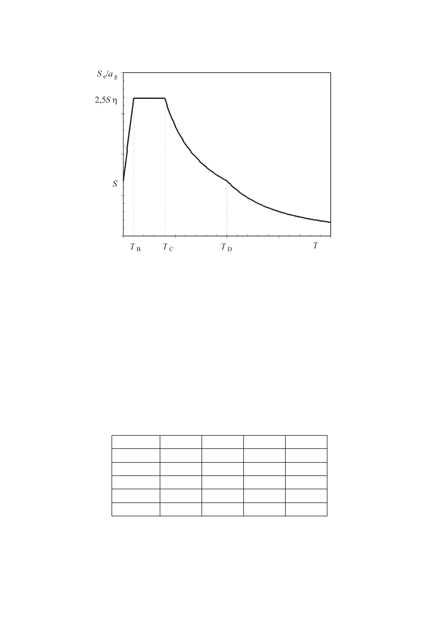
prEN 1998-1:2003 (E)
24
Figure 3.1: Shape of the elastic response spectrum
(2)P The values of the periods T
B
, T
C
and T
D
and of the soil factor S describing the
shape of the elastic response spectrum depend upon the ground type.
NOTE 1 The values to be ascribed to T
B
, T
C
, T
D
and S for each ground type and type (shape) of
spectrum to be used in a country may be found in its National Annex. If deep geology is not
accounted for (see 3.1.2(1) ), the recommended choice is the use of two types of spectra: Type 1
and Type 2. If the earthquakes that contribute most to the seismic hazard defined for the site for
the purpose of probabilistic hazard assessment have a surface-wave magnitude, M
s
, not greater
than 5,5, it is recommended that the Type 2 spectrum is adopted. For the five ground types A, B,
C, D and E the recommended values of the parameters S, T
B
, T
C
and T
D
are given in Table 3.2 for
the Type 1 Spectrum and in Table 3.3 for the Type 2 Spectrum. Figure 3.2 and Figure 3.3 show
the shapes of the recommended Type 1 and Type 2 spectra, respectively, normalised by a
g,
for
5% damping. Different spectra may be defined in the National Annex, if deep geology is
accounted for.
Table 3.2: Values of the parameters describing the recommended Type 1 elastic response spectra
Ground type
S T
B
(s)
T
C
(s)
T
D
(s)
A 1,0
0,15
0,4
2,0
B 1,2
0,15
0,5
2,0
C 1,15
0,20
0,6
2,0
D 1,35
0,20
0,8
2,0
E 1,4
0,15
0,5
2,0
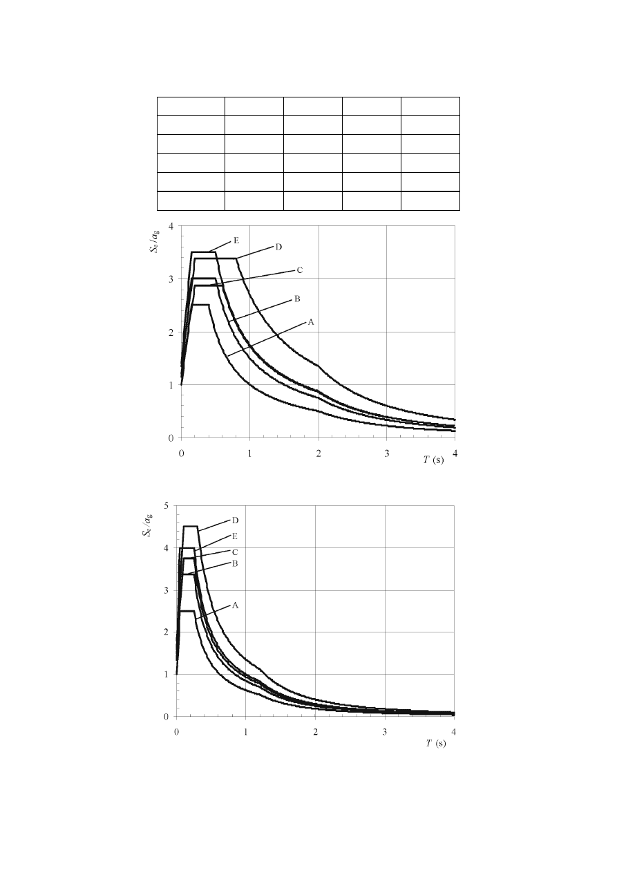
prEN 1998-1:2003 (E)
25
Table 3.3: Values of the parameters describing the recommended Type 2 elastic response spectra
Ground type
S T
B
(s)
T
C
(s)
T
D
(s)
A 1,0
0,05
0,25
1,2
B 1,35
0,05
0,25
1,2
C 1,5
0,10
0,25
1,2
D 1,8
0,10
0,30
1,2
E 1,6
0,05
0,25
1,2
Figure 3.2: Recommended Type 1 elastic response spectra for ground types A to E (5% damping)
Figure 3.3: Recommended Type 2 elastic response spectra for ground types A to E (5% damping)

prEN 1998-1:2003 (E)
26
Note 2 For ground types S
1
and S
2,
special studies should provide the corresponding values of S,
T
B
, T
C
and T
D.
(3)
The value of the damping correction factor
η may be determined by the
expression:
(
)
55
,
0
5
/
10
≥
+
=
ξ
η
(3.6)
where
ξ is the viscous damping ratio of the structure, expressed as a percentage.
(4)
If for special cases a viscous damping ratio different from 5% is to be used, this
value is given in the relevant Part of EN 1998.
(5)P The
elastic
displacement response spectrum, S
De
(T), shall be obtained by direct
transformation of the elastic acceleration response spectrum, S
e
(T), using the following
expression:
2
e
De
2
)
(
)
(
=
π
T
T
S
T
S
(3.7)
(6)
Expression (3.7) should normally be applied for vibration periods not exceeding
4,0 s. For structures with vibration periods longer than 4,0 s, a more complete definition
of the elastic displacement spectrum is possible.
NOTE For the Type 1 elastic response spectrum referred to in Note 1 to 3.2.2.2(2)P, such a
definition is presented in Informative Annex A in terms of the displacement response spectrum.
For periods longer than 4,0 s, the elastic acceleration response spectrum may be derived from the
elastic displacement response spectrum by inverting expression (3.7).
3.2.2.3 Vertical elastic response spectrum
(1)P The vertical component of the seismic action shall be represented by an elastic
response spectrum, S
ve
(T), derived using expressions (3.8)-(3.11).
( )
(
)
−
⋅
⋅
+
⋅
=
≤
≤
1
0
,
3
1
:
0
B
ve
B
η
T
T
a
T
S
T
T
vg
(3.8)
( )
0
,
3
:
vg
ve
C
B
⋅
⋅
=
≤
≤
η
a
T
S
T
T
T
(3.9)
( )
⋅
⋅
=
≤
≤
T
T
a
T
S
T
T
T
C
vg
ve
D
C
0
,
3
:
η
(3.10)
( )
.
0
,
3
:
s
4
2
D
C
vg
ve
D
⋅
⋅
=
≤
≤
T
T
T
a
T
S
T
T
η
(3.11)
NOTE The values to be ascribed to T
B
, T
C
, T
D
and a
vg
for each type (shape) of vertical spectrum
to be used in a country may be found in its National Annex. The recommended choice is the use
of two types of vertical spectra: Type 1 and Type 2. As for the spectra defining the horizontal
components of the seismic action, if the earthquakes that contribute most to the seismic hazard
defined for the site for the purpose of probabilistic hazard assessment have a surface-wave

prEN 1998-1:2003 (E)
27
magnitude, M
s
, not greater than 5,5, it is recommended that the Type 2 spectrum is adopted. For
the five ground types A, B, C, D and E the recommended values of the parameters describing the
vertical spectra are given in Table 3.4. These recommended values do not apply for special
ground types S
1
and S
2
.
Table 3.4: Recommended values of parameters describing the vertical elastic response spectra
Spectrum
a
vg
/a
g
T
B
(s)
T
C
(s)
T
D
(s)
Type 1
0,90
0,05
0,15
1,0
Type 2
0,45
0,05
0,15
1,0
3.2.2.4 Design ground displacement
(1)
Unless special studies based on the available information indicate otherwise, the
design ground displacement d
g
, corresponding to the design ground acceleration, may
be estimated by means of the following expression:
D
C
g
g
025
,
0
T
T
S
a
d
⋅
⋅
⋅
⋅
=
(3.12)
with a
g
, S, T
C
and T
D
as defined in 3.2.2.2.
3.2.2.5 Design spectrum for elastic analysis
(1)
The capacity of structural systems to resist seismic actions in the non-linear
range generally permits their design for resistance to seismic forces smaller than those
corresponding to a linear elastic response.
(2)
To avoid explicit inelastic structural analysis in design, the capacity of the
structure to dissipate energy, through mainly ductile behaviour of its elements and/or
other mechanisms, is taken into account by performing an elastic analysis based on a
response spectrum reduced with respect to the elastic one, henceforth called a ''design
spectrum''. This reduction is accomplished by introducing the behaviour factor q.
(3)P The behaviour factor q is an approximation of the ratio of the seismic forces that
the structure would experience if its response was completely elastic with 5% viscous
damping, to the seismic forces that may be used in the design, with a conventional
elastic analysis model, still ensuring a satisfactory response of the structure. The values
of the behaviour factor q, which also account for the influence of the viscous damping
being different from 5%, are given for various materials and structural systems
according to the relevant ductility classes in the various Parts of EN 1998. The value of
the behaviour factor q may be different in different horizontal directions of the structure,
although the ductility classification shall be the same in all directions.
(4)P For the horizontal components of the seismic action the design spectrum, S
d
(T),
shall be defined by the following expressions:
( )
−
⋅
+
⋅
⋅
=
≤
≤
3
2
5
,
2
3
2
:
0
B
g
d
B
q
T
T
S
a
T
S
T
T
(3.13)

prEN 1998-1:2003 (E)
28
( )
q
S
a
T
S
T
T
T
5
,
2
:
g
d
C
B
⋅
⋅
=
≤
≤
(3.14)
( )
5
,
2
=
:
g
C
g
d
D
C
⋅
≥
⋅
⋅
⋅
≤
≤
a
T
T
q
S
a
T
S
T
T
T
β
(3.15)
( )
5
,
2
=
:
g
2
D
C
g
d
D
⋅
≥
⋅
⋅
⋅
≤
a
T
T
T
q
S
a
T
S
T
T
β
(3.16)
where
a
g
, S, T
C
and T
D
are as defined in 3.2.2.2;
S
d
(T)
is the design spectrum;
q
is the behaviour factor;
β
is the lower bound factor for the horizontal design spectrum.
NOTE The value to be ascribed to
β for use in a country can be found in its National Annex. The
recommended value for
β is 0,2.
(5)
For the vertical component of the seismic action the design spectrum is given by
expressions (3.13) to (3.16), with the design ground acceleration in the vertical
direction, a
vg
replacing a
g
, S taken as being equal to 1,0 and the other parameters as
defined in 3.2.2.3.
(6)
For the vertical component of the seismic action a behaviour factor q up to to 1,5
should generally be adopted for all materials and structural systems.
(7)
The adoption of values for q greater than 1,5 in the vertical direction should be
justified through an appropriate analysis.
(8)P The design spectrum as defined above is not sufficient for the design of
structures with base-isolation or energy-dissipation systems.
3.2.3 Alternative
representations of the seismic action
3.2.3.1 Time - history representation
3.2.3.1.1 General
(1)P The seismic motion may also be represented in terms of ground acceleration
time-histories and related quantities (velocity and displacement).
(2)P When a spatial model is required, the seismic motion shall consist of three
simultaneously acting accelerograms. The same accelerogram may not be used
simultaneously along both horizontal directions. Simplifications are possible in
accordance with the relevant Parts of EN 1998.

prEN 1998-1:2003 (E)
29
(3)
Depending on the nature of the application and on the information actually
available, the description of the seismic motion may be made by using artificial
accelerograms (see 3.2.3.1.2) and recorded or simulated accelerograms (see 3.2.3.1.3).
3.2.3.1.2 Artificial accelerograms
(1)P Artificial accelerograms shall be generated so as to match the elastic response
spectra given in 3.2.2.2 and 3.2.2.3 for 5% viscous damping (
ξ = 5%).
(2)P The duration of the accelerograms shall be consistent with the magnitude and
the other relevant features of the seismic event underlying the establishment of a
g
.
(3)
When site-specific data are not available, the minimum duration T
s
of the
stationary part of the accelerograms should be equal to 10 s.
(4)
The suite of artificial accelerograms should observe the following rules:
a) a minimum of 3 accelerograms should be used;
b) the mean of the zero period spectral response acceleration values (calculated from the
individual time histories) should not be smaller than the value of a
g
.S for the site in
question.
c) in the range of periods between 0,2T
1
and 2T
1
, where T
1
is the fundamental period of
the structure in the direction where the accelerogram will be applied; no value of the
mean 5% damping elastic spectrum, calculated from all time histories, should be less
than 90% of the corresponding value of the 5% damping elastic response spectrum.
3.2.3.1.3 Recorded or simulated accelerograms
(1)P Recorded accelerograms, or accelerograms generated through a physical
simulation of source and travel path mechanisms, may be used, provided that the
samples used are adequately qualified with regard to the seismogenetic features of the
sources and to the soil conditions appropriate to the site, and their values are scaled to
the value of a
g
.S for the zone under consideration.
(2)P For soil amplification analyses and for dynamic slope stability verifications see
EN 1998-5:2004, 2.2.
(3)
The suite of recorded or simulated accelerograms to be used should satisfy
3.2.3.1.2(4).
3.2.3.2 Spatial model of the seismic action
(1)P For structures with special characteristics such that the assumption of the same
excitation at all support points cannot reasonably be made, spatial models of the seismic
action shall be used (see 3.2.2.1(8)).
(2)P Such spatial models shall be consistent with the elastic response spectra used for
the basic definition of the seismic action in accordance with 3.2.2.2 and 3.2.2.3.

prEN 1998-1:2003 (E)
30
3.2.4 Combinations of the seismic action with other actions
(1)P The
design
value
E
d
of the effects of actions in the seismic design situation shall
be determined in accordance with EN 1990:2002, 6.4.3.4.
(2)P The inertial effects of the design seismic action shall be evaluated by taking into
account the presence of the masses associated with all gravity loads appearing in the
following combination of actions:
i
k,
i
E,
j
k,
"
"
Q
G
⋅
+ ψ
Σ
Σ
(3.17)
where
ψ
E,i
is the combination coefficient for variable action i (see 4.2.4).
(3) The
combination
coefficients
ψ
E,i
take into account the likelihood of the loads
Q
k,i
not being present over the entire structure during the earthquake. These coefficients
may also account for a reduced participation of masses in the motion of the structure
due to the non-rigid connection between them.
(4) Values
of
ψ
2,i
are given in EN 1990:2002 and values of
ψ
E,i
for buildings or
other types of structures are given in the relevant parts of EN 1998.

prEN 1998-1:2003 (E)
31
4 DESIGN OF BUILDINGS
4.1 General
4.1.1 Scope
(1)P Section
4 contains general rules for the earthquake-resistant design of buildings
and shall be used in conjunction with Sections 2, 3 and 5 to 9.
(2) Sections
5 to 9 are concerned with specific rules for various materials and
elements used in buildings.
(3)
Guidance on base-isolated buildings is given in Section 10.
4.2 Characteristics of earthquake resistant buildings
4.2.1 Basic principles of conceptual design
(1)P In seismic regions the aspect of seismic hazard shall be taken into account in the
early stages of the conceptual design of a building, thus enabling the achievement of a
structural system which, within acceptable costs, satisfies the fundamental requirements
specified in 2.1.
(2)
The guiding principles governing this conceptual design are:
− structural simplicity;
− uniformity, symmetry and redundancy;
− bi-directional resistance and stiffness;
− torsional resistance and stiffness;
− diaphragmatic behaviour at storey level;
− adequate foundation.
These principles are further elaborated in the following subclauses.
4.2.1.1 Structural
simplicity
(1)
Structural simplicity, characterised by the existence of clear and direct paths for
the transmission of the seismic forces, is an important objective to be pursued, since the
modelling, analysis, dimensioning, detailing and construction of simple structures are
subject to much less uncertainty and thus the prediction of its seismic behaviour is much
more reliable.
4.2.1.2 Uniformity, symmetry and redundancy
(1)
Uniformity in plan is characterised by an even distribution of the structural
elements which allows short and direct transmission of the inertia forces created in the
distributed masses of the building. If necessary, uniformity may be realised by
subdividing the entire building by seismic joints into dynamically independent units,

prEN 1998-1:2003 (E)
32
provided that these joints are designed against pounding of the individual units in
accordance with 4.4.2.7.
(2)
Uniformity in the development of the structure along the height of the building
is also important, since it tends to eliminate the occurrence of sensitive zones where
concentrations of stress or large ductility demands might prematurely cause collapse.
(3)
A close relationship between the distribution of masses and the distribution of
resistance and stiffness eliminates large eccentricities between mass and stiffness.
(4)
If the building configuration is symmetrical or quasi-symmetrical, a symmetrical
layout of structural elements, which should be well-distributed in-plan, is appropriate
for the achievement of uniformity.
(5)
The use of evenly distributed structural elements increases redundancy and
allows a more favourable redistribution of action effects and widespread energy
dissipation across the entire structure.
4.2.1.3 Bi-directional resistance and stiffness
(1)P Horizontal seismic motion is a bi-directional phenomenon and thus the building
structure shall be able to resist horizontal actions in any direction.
(2) To
satisfy
(1)P, the structural elements should be arranged in an orthogonal in-
plan structural pattern, ensuring similar resistance and stiffness characteristics in both
main directions.
(3)
The choice of the stiffness characteristics of the structure, while attempting to
minimise the effects of the seismic action (taking into account its specific features at the
site) should also limit the development of excessive displacements that might lead to
either instabilities due to second order effects or excessive damages.
4.2.1.4 Torsional resistance and stiffness
(1)
Besides lateral resistance and stiffness, building structures should possess
adequate torsional resistance and stiffness in order to limit the development of torsional
motions which tend to stress the different structural elements in a non-uniform way . In
this respect, arrangements in which the main elements resisting the seismic action are
distributed close to the periphery of the building present clear advantages.
4.2.1.5 Diaphragmatic behaviour at storey level
(1)
In buildings, floors (including the roof) play a very important role in the overall
seismic behaviour of the structure. They act as horizontal diaphragms that collect and
transmit the inertia forces to the vertical structural systems and ensure that those
systems act together in resisting the horizontal seismic action. The action of floors as
diaphragms is especially relevant in cases of complex and non-uniform layouts of the
vertical structural systems, or where systems with different horizontal deformability
characteristics are used together (e.g. in dual or mixed systems).
(2)
Floor systems and the roof should be provided with in-plane stiffness and
resistance and with effective connection to the vertical structural systems. Particular

prEN 1998-1:2003 (E)
33
care should be taken in cases of non-compact or very elongated in-plan shapes and in
cases of large floor openings, especially if the latter are located in the vicinity of the
main vertical structural elements, thus hindering such effective connection between the
vertical and horizontal structure.
(3)
Diaphragms should have sufficient in-plane stiffness for the distribution of
horizontal inertia forces to the vertical structural systems in accordance with the
assumptions of the analysis (e.g. rigidity of the diaphragm, see 4.3.1(4)), particularly
when there are significant changes in stiffness or offsets of vertical elements above and
below the diaphragm.
4.2.1.6 Adequate
foundation
(1)P With regard to the seismic action, the design and construction of the foundations
and of the connection to the superstructure shall ensure that the whole building is
subjected to a uniform seismic excitation.
(2)
For structures composed of a discrete number of structural walls, likely to differ
in width and stiffness, a rigid, box-type or cellular foundation, containing a foundation
slab and a cover slab should generally be chosen.
(3)
For buildings with individual foundation elements (footings or piles), the use of
a foundation slab or tie-beams between these elements in both main directions is
recommended, subject to the criteria and rules of EN 1998-5:2004, 5.4.1.2.
4.2.2 Primary and secondary seismic members
(1)P A certain number of structural members (e.g. beams and/or columns) may be
designated as “secondary” seismic members (or elements), not forming part of the
seismic action resisting system of the building. The strength and stiffness of these
elements against seismic actions shall be neglected. They do not need to conform to the
requirements of Sections 5 to 9. Nonetheless these members and their connections shall
be designed and detailed to maintain support of gravity loading when subjected to the
displacements caused by the most unfavourable seismic design condition. Due
allowance of 2
nd
order effects (P-
∆ effects) should be made in the design of these
members.
(2) Sections
5 to 9 give rules, in addition to those of EN 1992, EN 1993, EN 1994,
EN 1995 and EN 1996, for the design and detailing of secondary seismic elements.
(3)
All structural members not designated as being secondary seismic members are
taken as being primary seismic members. They are taken as being part of the lateral
force resisting system, should be modelled in the structural analysis in accordance with
4.3.1 and designed and detailed for earthquake resistance in accordance with the rules of
Sections 5 to 9.
(4)
The total contribution to lateral stiffness of all secondary seismic members
should not exceed 15% of that of all primary seismic members.
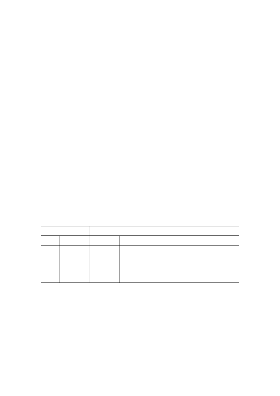
prEN 1998-1:2003 (E)
34
(5)
The designation of some structural elements as secondary seismic members is
not allowed to change the classification of the structure from non-regular to regular as
described in 4.2.3.
4.2.3 Criteria for structural regularity
4.2.3.1 General
(1)P For the purpose of seismic design, building structures are categorised into being
regular or non-regular.
NOTE In building structures consisting of more than one dynamically independent units, the
categorisation and the relevant criteria in 4.2.3 refer to the individual dynamically independent
units. In such structures, “individual dynamically independent unit” is meant for “building” in
4.2.3.
(2)
This distinction has implications for the following aspects of the seismic design:
− the structural model, which can be either a simplified planar model or a spatial
model ;
− the method of analysis, which can be either a simplified response spectrum analysis
(lateral force procedure) or a modal one;
− the value of the behaviour factor q, which shall be decreased for buildings
non-regular in elevation (see 4.2.3.3).
(3)P With regard to the implications of structural regularity on analysis and design,
separate consideration is given to the regularity characteristics of the building in plan
and in elevation (Table 4.1).
Table 4.1: Consequences of structural regularity on seismic analysis and design
Regularity Allowed
Simplification Behaviour
factor
Plan Elevation Model
Linear-elastic Analysis
(for linear analysis)
Yes
Yes
No
No
Yes
No
Yes
No
Planar
Planar
Spatial
b
Spatial
Lateral force
a
Modal
Lateral force
a
Modal
Reference value
Decreased value
Reference value
Decreased value
a
If the condition of 4.3.3.2.1(2)a) is also met.
b
Under the specific conditions given in 4.3.3.1(8) a separate planar model may be used in each horizontal
direction, in accordance with 4.3.3.1(8).
(4)
Criteria describing regularity in plan and in elevation are given in 4.2.3.2 and
4.2.3.3. Rules concerning modelling and analysis are given in 4.3.
(5)P The regularity criteria given in 4.2.3.2 and 4.2.3.3 should be taken as necessary
conditions. It shall be verified that the assumed regularity of the building structure is not
impaired by other characteristics, not included in these criteria.
(6)
The reference values of the behaviour factors are given in Sections 5 to 9.

prEN 1998-1:2003 (E)
35
(7)
For non-regular in elevation buildings the decreased values of the behaviour
factor are given by the reference values multiplied by 0,8.
4.2.3.2 Criteria for regularity in plan
(1)P For a building to be categorised as being regular in plan, it shall satisfy all the
conditions listed in the following paragraphs.
(2)
With respect to the lateral stiffness and mass distribution, the building structure
shall be approximately symmetrical in plan with respect to two orthogonal axes.
(3)
The plan configuration shall be compact, i.e., each floor shall be delimited by a
polygonal convex line. If in plan set-backs (re-entrant corners or edge recesses) exist,
regularity in plan may still be considered as being satisfied, provided that these set-
backs do not affect the floor in-plan stiffness and that, for each set-back, the area
between the outline of the floor and a convex polygonal line enveloping the floor does
not exceed 5 % of the floor area.
(4)
The in-plan stiffness of the floors shall be sufficiently large in comparison with
the lateral stiffness of the vertical structural elements, so that the deformation of the
floor shall have a small effect on the distribution of the forces among the vertical
structural elements. In this respect, the L, C, H, I, and X plan shapes should be carefully
examined, notably as concerns the stiffness of the lateral branches, which should be
comparable to that of the central part, in order to satisfy the rigid diaphragm condition.
The application of this paragraph should be considered for the global behaviour of the
building.
(5) The
slenderness
λ = L
max
/L
min
of the building in plan shall be not higher than 4,
where L
max
and L
min
are respectively the larger and smaller in plan dimension of the
building, measured in orthogonal directions.
(6)
At each level and for each direction of analysis x and y, the structural
eccentricity e
o
and the torsional radius r shall be in accordance with the two conditions
below, which are expressed for the direction of analysis y:
x
ox
30
,
0
r
e
⋅
≤
(4.1a)
s
x
l
r
≥ (4.1b)
where
e
ox
is the distance between the centre of stiffness and the centre of mass, measured
along the x direction, which is normal to the direction of analysis considered;
r
x
is the square root of the ratio of the torsional stiffness to the lateral stiffness in
the y direction (“torsional radius”); and
l
s
is the radius of gyration of the floor mass in plan (square root of the ratio of (a)
the polar moment of inertia of the floor mass in plan with respect to the centre of
mass of the floor to (b) the floor mass).

prEN 1998-1:2003 (E)
36
The definitions of centre of stiffness and torsional radius r
are provided in (7) to (9) of
this subclause .
(7)
In single storey buildings the centre of stiffness is defined as the centre of the
lateral stiffness of all primary seismic members. The torsional radius r is defined as the
square root of the ratio of the global torsional stiffness with respect to the centre of
lateral stiffness, and the global lateral stiffness, in one direction, taking into account all
of the primary seismic members in this direction.
(8)
In multi-storey buildings only approximate definitions of the centre of stiffness
and of the torsional radius are possible. A simplified definition, for the classification of
structural regularity in plan and for the approximate analysis of torsional effects, is
possible if the following two conditions are satisfied:
a) all lateral load resisting systems, such as cores, structural walls, or frames, run
without interruption from the foundations to the top of the building;
b) the deflected shapes of the individual systems under horizontal loads are not very
different. This condition may be considered satisfied in the case of frame systems and
wall systems. In general, this condition is not satisfied in dual systems.
NOTE The National Annex can include reference to documents that might provide definitions of
the centre of stiffness and of the torsional radius in multi-storey buildings, both for those that
meet the conditions (a) and (b) of paragraph (8), and for those that do not.
(9)
In frames and in systems of slender walls with prevailing flexural deformations,
the position of the centres of stiffness and the torsional radius of all storeys may be
calculated as those of the moments of inertia of the cross-sections of the vertical
elements. If, in addition to flexural deformations, shear deformations are also
significant, they may be accounted for by using an equivalent moment of inertia of the
cross-section.
4.2.3.3 Criteria for regularity in elevation
(1)P For a building to be categorised as being regular in elevation, it shall satisfy all
the conditions listed in the following paragraphs.
(2)
All lateral load resisting systems, such as cores, structural walls, or frames, shall
run without interruption from their foundations to the top of the building or, if setbacks
at different heights are present, to the top of the relevant zone of the building.
(3)
Both the lateral stiffness and the mass of the individual storeys shall remain
constant or reduce gradually, without abrupt changes, from the base to the top of a
particular building.
(4)
In framed buildings the ratio of the actual storey resistance to the resistance
required by the analysis should not vary disproportionately between adjacent storeys.
Within this context the special aspects of masonry infilled frames are treated in
4.3.6.3.2.
(5)
When setbacks are present, the following additional conditions apply:
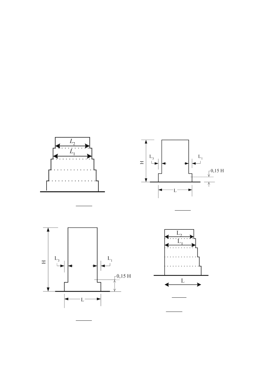
prEN 1998-1:2003 (E)
37
a) for gradual setbacks preserving axial symmetry, the setback at any floor shall be not
greater than 20 % of the previous plan dimension in the direction of the setback (see
Figure 4.1.a and Figure 4.1.b);
b) for a single setback within the lower 15 % of the total height of the main structural
system, the setback shall be not greater than 50 % of the previous plan dimension (see
Figure 4.1.c). In this case the structure of the base zone within the vertically projected
perimeter of the upper storeys should be designed to resist at least 75% of the horizontal
shear forces that would develop in that zone in a similar building without the base
enlargement;
c) if the setbacks do not preserve symmetry, in each face the sum of the setbacks at all
storeys shall be not greater than 30 % of the plan dimension at the ground floor above
the foundation or above the top of a rigid basement, and the individual setbacks shall be
not greater than 10 % of the previous plan dimension (see Figure 4.1.d).
(a)
Criterion for (a):
0,20
1
2
1
≤
−
L
L
L
(b) (setback occurs above 0,15H)
Criterion for (b):
0,20
1
3
≤
+
L
L
L
(c) (setback occurs below 0,15H)
Criterion for (c):
0,50
1
3
≤
+
L
L
L
d)
Criteria for (d):
0,30
2
≤
−
L
L
L
0,10
1
2
1
≤
−
L
L
L
Figure 4.1: Criteria for regularity of buildings with setbacks

prEN 1998-1:2003 (E)
38
4.2.4 Combination
coefficients for variable actions
(1)P The combination coefficients
ψ
2i
(for the quasi-permanent value of variable
action q
i
) for the design of buildings (see 3.2.4) shall be those given in EN 1990:2002,
Annex A1.
(2)P The combination coefficients
ψ
Ei
introduced in 3.2.4(2)P for the calculation of
the effects of the seismic actions shall be computed from the following expression:
2i
Ei
ψ
ϕ
ψ
⋅
=
(4.2)
NOTE The values to be ascribed to
ϕ for use in a country may be found in its National Annex.
The recommended values for
ϕ are listed in Table 4.2.
Table 4.2: Values of
ϕ for calculating ψ
Ei
Type of variable
action
Storey
ϕ
Categories A-C
*
Roof
Storeys with correlated occupancies
Independently occupied storeys
1,0
0,8
0,5
Categories D-F
*
and Archives
1,0
* Categories as defined in EN 1991-1-1:2002.
4.2.5 Importance classes and importance factors
(1)P Buildings are classified in 4 importance classes, depending on the consequences
of collapse for human life, on their importance for public safety and civil protection in
the immediate post-earthquake period, and on the social and economic consequences of
collapse.
(2)P The importance classes are characterised by different importance factors
γ
I
as
described in 2.1(3).
(3)
The importance factor
γ
I
= 1,0 is associated with a seismic event having the
reference return period indicated in 3.2.1(3).
(4)
The definitions of the importance classes are given in Table 4.3.

prEN 1998-1:2003 (E)
39
Table 4.3 Importance classes for buildings
Importance
class
Buildings
I
Buildings of minor importance for public safety, e.g. agricultural
buildings, etc.
II
Ordinary buildings, not belonging in the other categories.
III
Buildings whose seismic resistance is of importance in view of the
consequences associated with a collapse, e.g. schools, assembly halls,
cultural institutions etc.
IV
Buildings whose integrity during earthquakes is of vital importance
for civil protection, e.g. hospitals, fire stations, power plants, etc.
NOTE Importance classes I, II and III or IV correspond roughly to consequences classes CC1,
CC2 and CC3, respectively, defined in EN 1990:2002, Annex B.
(5)P The value of
γ
I
for importance class II shall be, by definition, equal to 1,0.
NOTE The values to be ascribed to
γ
I
for use in a country may be found in its National Annex.
The values of
γ
I
may be different for the various seismic zones of the country, depending on the
seismic hazard conditions and on public safety considerations (see Note to 2.1(4)). The
recommended values of
γ
I
for importance classes I, III and IV are equal to 0,8, 1,2 and 1,4,
respectively.
(6)
For buildings which house dangerous installations or materials the importance
factor should be established in accordance with the criteria set forth in EN 1998-4.
4.3 Structural
analysis
4.3.1 Modelling
(1)P The model of the building shall adequately represent the distribution of stiffness
and mass in it so that all significant deformation shapes and inertia forces are properly
accounted for under the seismic action considered. In the case of non-linear analysis, the
model shall also adequately represent the distribution of strength.
(2)
The model should also account for the contribution of joint regions to the
deformability of the building, e.g. the end zones in beams or columns of frame type
structures. Non-structural elements, which may influence the response of the primary
seismic structure, should also be accounted for.
(3)
In general the structure may be considered to consist of a number of vertical and
lateral load resisting systems, connected by horizontal diaphragms.
(4)
When the floor diaphragms of the building may be taken as being rigid in their
planes, the masses and the moments of inertia of each floor may be lumped at the centre
of gravity.
NOTE The diaphragm is taken as being rigid, if, when it is modelled with its actual in-plane
flexibility, its horizontal displacements nowhere exceed those resulting from the rigid diaphragm
assumption by more than 10% of the corresponding absolute horizontal displacements in the
seismic design situation.

prEN 1998-1:2003 (E)
40
(5)
For buildings conforming to the criteria for regularity in plan (see 4.2.3.2) or
with the conditions presented in 4.3.3.1(8), the analysis may be performed using two
planar models, one for each main direction.
(6)
In concrete buildings, in composite steel-concrete buildings and in masonry
buildings the stiffness of the load bearing elements should, in general, be evaluated
taking into account the effect of cracking. Such stiffness should correspond to the
initiation of yielding of the reinforcement.
(7)
Unless a more accurate analysis of the cracked elements is performed, the elastic
flexural and shear stiffness properties of concrete and masonry elements may be taken
to be equal to one-half of the corresponding stiffness of the uncracked elements.
(8)
Infill walls which contribute significantly to the lateral stiffness and resistance of
the building should be taken into account. See 4.3.6 for masonry infills of concrete,
steel or composite frames.
(9)P The deformability of the foundation shall be taken into account in the model,
whenever it may have an adverse overall influence on the structural response.
NOTE Foundation deformability (including the soil-structure interaction) may always be taken
into account, including the cases in which it has beneficial effects.
(10)P The masses shall be calculated from the gravity loads appearing in the
combination of actions indicated in 3.2.4. The combination coefficients
ψ
Ei
are given in
4.2.4(2)P.
4.3.2 Accidental torsional effects
(1)P In order to account for uncertainties in the location of masses and in the spatial
variation of the seismic motion, the calculated centre of mass at each floor i shall be
considered as being displaced from its nominal location in each direction by an
accidental eccentricity:
i
ai
05
,
0
L
e
⋅
±
=
(4.3)
where
e
ai
is the accidental eccentricity of storey mass i from its nominal location, applied
in the same direction at all floors;
L
i
is the floor-dimension perpendicular to the direction of the seismic action.
4.3.3 Methods
of
analysis
4.3.3.1 General
(1)
Within the scope of Section 4, the seismic effects and the effects of the other
actions included in the seismic design situation may be determined on the basis of the
linear-elastic behaviour of the structure.

prEN 1998-1:2003 (E)
41
(2)P The reference method for determining the seismic effects shall be the modal
response spectrum analysis, using a linear-elastic model of the structure and the design
spectrum given in 3.2.2.5.
(3)
Depending on the structural characteristics of the building one of the following
two types of linear-elastic analysis may be used:
a) the “lateral force method of analysis” for buildings meeting the conditions given in
4.3.3.2;
b) the “modal response spectrum analysis", which is applicable to all types of buildings
(see 4.3.3.3).
(4)
As an alternative to a linear method, a non-linear method may also be used, such
as:
c) non-linear static (pushover) analysis;
d) non-linear time history (dynamic) analysis,
provided that the conditions specified in (5) and (6) of this subclause and in 4.3.3.4 are
satisfied.
NOTE For base isolated buildings the conditions under which the linear methods a) and b) or the
nonlinear ones c) and d), may be used are given in Section 10. For non-base-isolated buildings,
the linear methods of 4.3.3.1(3) may always be used, as specified in 4.3.3.2.1. The choice of
whether the nonlinear methods of 4.3.3.1(4) may also be applied to non-base-isolated buildings
in a particular country , will be found in its National Annex. The National Annex may also
include reference to complementary information about member deformation capacities and the
associated partial factors to be used in the Ultimate Limit State verifications in accordance with
4.4.2.2(5).
(5)
Non-linear analyses should be properly substantiated with respect to the seismic
input, the constitutive model used, the method of interpreting the results of the analysis
and the requirements to be met.
(6)
Non-base-isolated structures designed on the basis of non-linear pushover
analysis without using the behaviour factor q (see 4.3.3.4.2.1(1)d), should satisfy
4.4.2.2(5), as well as the rules of Sections 5 to 9 for dissipative structures.
(7)
Linear-elastic analysis may be performed using two planar models, one for each
main horizontal direction, if the criteria for regularity in plan are satisfied (see 4.2.3.2).
(8)
Depending on the importance class of the building, linear-elastic analysis may
be performed using two planar models, one for each main horizontal direction, even if
the criteria for regularity in plan in 4.2.3.2 are not satisfied, provided that all of the
following special regularity conditions are met:
a) the building shall have well-distributed and relatively rigid cladding and partitions;
b) the building height shall not exceed 10 m;

prEN 1998-1:2003 (E)
42
c) the in-plane stiffness of the floors shall be large enough in comparison with the
lateral stiffness of the vertical structural elements, so that a rigid diaphragm behaviour
may be assumed.
d) the centres of lateral stiffness and mass shall be each approximately on a vertical line
and, in the two horizontal directions of analysis, satisfy the conditions: r
x
2
> l
s
2
+ e
ox
2
,
r
y
2
> l
s
2
+ e
oy
2
, where the radius of gyration l
s,
the torsional radii r
x
and r
y
and the natural
eccentricities e
ox
and e
oy
are defined as in 4.2.3.2(6).
NOTE The value of the importance factor,
γ
I
, below which the simplification of the analysis in
accordance with 4.3.3.1(8) is allowed in a country, may be found in its National Annex.
(9)
In buildings satisfying all the conditions of (8) of this subclause with the
exception of d), linear-elastic analysis using two planar models, one for each main
horizontal direction, may also be performed, but in such cases all seismic action effects
resulting from the analysis should be multiplied by 1,25.
(10)P Buildings not conforming to the criteria in (7) to (9) of this clause shall be
analysed using a spatial model.
(11)P Whenever a spatial model is used, the design seismic action shall be applied
along all relevant horizontal directions (with regard to the structural layout of the
building) and their orthogonal horizontal directions. For buildings with resisting
elements in two perpendicular directions these two directions shall be considered as the
relevant directions.
4.3.3.2 Lateral force method of analysis
4.3.3.2.1 General
(1)P This type of analysis may be applied to buildings whose response is not
significantly affected by contributions from modes of vibration higher than the
fundamental mode in each principal direction.
(2)
The requirement in (1)P of this subclause is deemed to be satisfied in buildings
which fulfil both of the two following conditions.
a) they have fundamental periods of vibration T
1
in the two main directions which are
smaller than the following values
⋅
≤
s
0
,
2
4
C
1
T
T
(4.4)
where T
C
is given in Table 3.2 or Table 3.3;
b) they meet the criteria for regularity in elevation given in 4.2.3.3.
4.3.3.2.2 Base shear force
(1)P The seismic base shear force F
b
, for each horizontal direction in which the
building is analysed, shall be determined using the following expression:

prEN 1998-1:2003 (E)
43
( )
λ
⋅
⋅
=
m
T
S
F
1
d
b
(4.5)
where
S
d
(T
1
) is the ordinate of the design spectrum (see 3.2.2.5) at period T
1
;
T
1
is the fundamental period of vibration of the building for lateral motion in the
direction considered;
m
is the total mass of the building, above the foundation or above the top of a rigid
basement, computed in accordance with 3.2.4(2);
λ
is the correction factor, the value of which is equal to:
λ = 0,85 if T
1
< 2 T
C
and
the building has more than two storeys, or
λ = 1,0 otherwise.
NOTE The factor
λ accounts for the fact that in buildings with at least three storeys and
translational degrees of freedom in each horizontal direction, the effective modal mass of the 1
st
(fundamental) mode is smaller, on average by 15%, than the total building mass.
(2)
For the determination of the fundamental period of vibration period T
1
of the
building, expressions based on methods of structural dynamics (for example the
Rayleigh method) may be used.
(3)
For buildings with heights of up to 40 m the value of T
1
(in s) may be
approximated by the following expression:
4
/
3
t
1
H
C
T
⋅
=
(4.6)
where
C
t
is 0,085 for moment resistant space steel frames, 0,075 for moment resistant
space concrete frames and for eccentrically braced steel frames and 0,050 for all
other structures;
H
is the height of the building, in m, from the foundation or from the top of a rigid
basement.
(4)
Alternatively, for structures with concrete or masonry shear walls the value C
t
in
expression (4.6) may be taken as being
c
t
/
075
,
0
A
C
=
(4.7)
where
(
)
(
)
[
]
2
wi
i
c
/
2
,
0
H
l
A
A
+
⋅
= Σ
(4.8)
and
A
c
is the total effective area of the shear walls in the first storey of the building, in
m
2
;
A
i
is the effective cross-sectional area of the shear wall i in the first storey of the
building, in m
2
;

prEN 1998-1:2003 (E)
44
H
is as in (3) of this subclause;
l
wi
is the length of the shear wall i in the first storey in the direction parallel to the
applied forces, in m, with the restriction that l
wi
/H should not exceed 0,9.
(5)
Alternatively, the estimation of T
1
(in s) may be made by using the following
expression:
d
T
⋅
= 2
1
(4.9)
where
d
is the lateral elastic displacement of the top of the building, in m, due to the
gravity loads applied in the horizontal direction.
4.3.3.2.3 Distribution of the horizontal seismic forces
(1)
The fundamental mode shapes in the horizontal directions of analysis of the
building may be calculated using methods of structural dynamics or may be
approximated by horizontal displacements increasing linearly along the height of the
building.
(2)P The seismic action effects shall be determined by applying, to the two planar
models, horizontal forces F
i
to all storeys.
j
j
i
i
b
i
m
s
m
s
F
F
⋅
⋅
⋅
=
Σ
(4.10)
where
F
i
is the horizontal force acting on storey i;
F
b
is the seismic base shear in accordance with expression (4.5);
s
i
, s
j
are the
displacements of masses m
i
, m
j
in the fundamental mode shape;
m
i
,
m
j
are the storey masses computed in accordance with 3.2.4(2).
(3)
When the fundamental mode shape is approximated by horizontal displacements
increasing linearly along the height, the horizontal forces F
i
should be taken as being
given by:
j
j
i
i
b
i
m
z
m
z
F
F
⋅
⋅
⋅
=
Σ
(4.11)
where
z
i
, z
j
are the heights of the masses m
i
m
j
above the level of application of the seismic
action (foundation or top of a rigid basement).
(4)P The horizontal forces F
i
determined in accordance with this clause shall be
distributed to the lateral load resisting system assuming the floors are rigid in their
plane.

prEN 1998-1:2003 (E)
45
4.3.3.2.4 Torsional effects
(1)
If the lateral stiffness and mass are symmetrically distributed in plan and unless
the accidental eccentricity of 4.3.2(1)P is taken into account by a more exact method
(e.g. that of 4.3.3.3.3(1)), the accidental torsional effects may be accounted for by
multiplying the action effects in the individual load resisting elements resulting from the
application of 4.3.3.2.3(4) by a factor
δ given by
e
6
,
0
1
L
x
⋅
+
=
δ
(4.12)
where
x
is the distance of the element under consideration from the centre of mass of the
building in plan, measured perpendicularly to the direction of the seismic action
considered;
L
e
is the distance between the two outermost lateral load resisting elements,
measured perpendicularly to the direction of the seismic action considered.
(2)
If the analysis is performed using two planar models, one for each main
horizontal direction, torsional effects may be determined by doubling the accidental
eccentricity e
ai
of expression (4.3) and applying (1) of this subclause with factor 0,6 in
expression (4.12) increased to 1,2.
4.3.3.3 Modal response spectrum analysis
4.3.3.3.1 General
(1)P This type of analysis shall be applied to buildings which do not satisfy the
conditions given in 4.3.3.2.1(2) for applying the lateral force method of analysis.
(2)P The response of all modes of vibration contributing significantly to the global
response shall be taken into account.
(3)
The requirements specified in paragraph (2)P may be deemed to be satisfied if
either of the following can be demonstrated:
− the sum of the effective modal masses for the modes taken into account amounts to
at least 90% of the total mass of the structure;
− all modes with effective modal masses greater than 5% of the total mass are taken
into account.
NOTE The effective modal mass m
k
, corresponding to a mode k, is determined so that the base
shear force F
bk
, acting in the direction of application of the seismic action, may be expressed as
F
bk
= S
d
(T
k
) m
k
. It can be shown that the sum of the effective modal masses (for all modes and a
given direction) is equal to the mass of the structure.
(4)
When using a spatial model, the above conditions should be verified for each
relevant direction.

prEN 1998-1:2003 (E)
46
(5)
If the requirements specified in (3) cannot be satisfied (e.g. in buildings with a
significant contribution from torsional modes), the minimum number k of modes to be
taken into account in a spatial analysis should satisfy both the two following conditions:
n
k
⋅
≥ 3
(4.14a)
and
s
20
,
0
k
≤
T
(4.14b)
where
k
is the number of modes taken into account;
n
is the number of storeys above the foundation or the top of a rigid basement;
T
k
is the period of vibration of mode k.
4.3.3.3.2 Combination of modal responses
(1)
The response in two vibration modes i and j (including both translational and
torsional modes) may be taken as independent of each other, if their periods T
i
and T
j
satisfy (with T
j
≤
T
i
) the following condition:
i
j
9
,
0
T
T
⋅
≤
(4.15)
(2)
Whenever all relevant modal responses (see 4.3.3.3.1(3)-(5)) may be regarded as
independent of each other, the maximum value E
E
of a seismic action effect may be
taken as:
2
Ei
E
E
E
Σ
=
(4.16)
where
E
E
is the seismic action effect under consideration (force, displacement, etc.);
E
Ei
is the value of this seismic action effect due to the vibration mode i.
(3)P If
(1) is not satisfied, more accurate procedures for the combination of the modal
maxima, such as the "Complete Quadratic Combination" shall be adopted.
4.3.3.3.3 Torsional effects
(1)
Whenever a spatial model is used for the analysis, the accidental torsional
effects referred to in 4.3.2(1)P may be determined as the envelope of the effects
resulting from the application of static loadings, consisting of sets of torsional moments
M
ai
about the vertical axis of each storey i:
i
ai
ai
F
e
M
⋅
=
(4.17)
where
M
ai
is the torsional moment applied at storey i about its vertical axis;

prEN 1998-1:2003 (E)
47
e
ai
is the accidental eccentricity of storey mass i in accordance with expression (4.3)
for all relevant directions;
F
i
is the horizontal force acting on storey i, as derived in 4.3.3.2.3 for all relevant
directions.
(2)
The effects of the loadings in accordance with (1) should be taken into account
with positive and negative signs (the same sign for all storeys).
(3)
Whenever two separate planar models are used for the analysis, the torsional
effects may be accounted for by applying the rules of 4.3.3.2.4(2) to the action effects
computed in accordance with 4.3.3.3.2.
4.3.3.4 Non-linear
methods
4.3.3.4.1 General
(1)P The mathematical model used for elastic analysis shall be extended to include
the strength of structural elements and their post-elastic behaviour.
(2)
As a minimum, a bilinear force–deformation relationship should be used at the
element level. In reinforced concrete and masonry buildings, the elastic stiffness of a
bilinear force-deformation relation should correspond to that of cracked sections (see
4.3.1(7)). In ductile elements, expected to exhibit post-yield excursions during the
response, the elastic stiffness of a bilinear relation should be the secant stiffness to the
yield-point. Trilinear force–deformation relationships, which take into account pre-
crack and post-crack stiffnesses, are allowed.
(3)
Zero post-yield stiffness may be assumed. If strength degradation is expected,
e.g. for masonry walls or other brittle elements, it has to be included in the force–
deformation relationships of those elements.
(4)
Unless otherwise specified, element properties should be based on mean values
of the properties of the materials. For new structures, mean values of material properties
may be estimated from the corresponding characteristic values on the basis of
information provided in EN 1992 to EN 1996 or in material ENs.
(5)P Gravity loads in accordance with 3.2.4 shall be applied to appropriate elements
of the mathematical model.
(6)
Axial forces due to gravity loads should be taken into account when determining
force – deformation relations for structural elements. Bending moments in vertical
structural elements due to gravity loads may be neglected, unless they substantially
influence the global structural behaviour.
(7)P The seismic action shall be applied in both positive and negative directions and
the maximum seismic effects as a result of this shall be used.

prEN 1998-1:2003 (E)
48
4.3.3.4.2 Non-linear static (pushover) analysis
4.3.3.4.2.1 General
(1)
Pushover analysis is a non-linear static analysis carried out under conditions of
constant gravity loads and monotonically increasing horizontal loads. It may be applied
to verify the structural performance of newly designed and of existing buildings for the
following purposes:
a) to verify or revise the overstrength ratio values
α
u
/
α
1
(see 5.2.2.2, 6.3.2, 7.3.2);
b) to estimate the expected plastic mechanisms and the distribution of damage;
c) to assess the structural performance of existing or retrofitted buildings for the
purposes of EN 1998-3;
d) as an alternative to the design based on linear-elastic analysis which uses the
behaviour factor q. In that case, the target displacement indicated in 4.3.3.4.2.6(1)P
should be used as the basis of the design.
(2)P Buildings not conforming to the regularity criteria of 4.2.3.2 or the criteria of
4.3.3.1(8)a)-e) shall be analysed using a spatial model. Two independent analyses with
lateral loads applied in one direction only may be performed.
(3)
For buildings conforming to the regularity criteria of 4.2.3.2 or the criteria of
4.3.3.1(8)a)-d) the analysis may be performed using two planar models, one for each
main horizontal direction.
(4)
For low-rise masonry buildings, in which structural wall behaviour is dominated
by shear, each storey may be analysed independently.
(5)
The requirements in (4) are deemed to be satisfied if the number of storeys is 3
or less and if the average aspect (height to width) ratio of structural walls is less than
1,0.
4.3.3.4.2.2 Lateral loads
(1)
At least two vertical distributions of the lateral loads should be applied:
− a “uniform” pattern, based on lateral forces that are proportional to mass regardless
of elevation (uniform response acceleration);
− a “modal” pattern, proportional to lateral forces consistent with the lateral force
distribution in the direction under consideration determined in elastic analysis (in
accordance with 4.3.3.2 or 4.3.3.3).
(2)P Lateral loads shall be applied at the location of the masses in the model.
Accidental eccentricity in accordance with 4.3.2(1)P shall be taken into account.
4.3.3.4.2.3 Capacity curve
(1)
The relation between base shear force and the control displacement (the
“capacity curve”) should be determined by pushover analysis for values of the control

prEN 1998-1:2003 (E)
49
displacement ranging between zero and the value corresponding to 150% of the target
displacement, defined in 4.3.3.4.2.6.
(2)
The control displacement may be taken at the centre of mass of the roof of the
building. The top of a penthouse should not be considered as the roof.
4.3.3.4.2.4 Overstrength factor
(1)
When the overstrength ratio (
α
u
/
α
1
) is determined by pushover analysis, the
lower value of the overstrength factor obtained for the two lateral load distributions
should be used.
4.3.3.4.2.5 Plastic mechanism
(1)P The plastic mechanism shall be determined for the two lateral load distributions
applied. The plastic mechanisms shall conform to the mechanisms on which the
behaviour factor q used in the design is based.
4.3.3.4.2.6 Target displacement
(1)P The target displacement shall be defined as the seismic demand derived from the
elastic response spectrum of 3.2.2.2 in terms of the displacement of an equivalent
single-degree-of-freedom system.
NOTE Informative Annex B gives a procedure for the determination of the target displacement
from the elastic response spectrum.
4.3.3.4.2.7 Procedure for the estimation of the torsional effects
(1)P Pushover analysis performed with the force patterns specified in 4.3.3.4.2.2
may
significantly underestimate deformations at the stiff/strong side of a torsionally flexible
structure, i.e. a structure with a predominantly torsional first mode of vibration. The
same applies for the stiff/strong side deformations in one direction of a structure with a
predominately torsional second mode of vibration. For such structures, displacements at
the stiff/strong side shall be increased, compared to those in the corresponding
torsionally balanced structure.
NOTE The stiff/strong side in plan is the one that develops smaller horizontal displacements
than the opposite side, under static lateral forces parallel to it. For torsionally flexible structures,
the dynamic displacements at the stiff/strong side may considerably increase due to the influence
of the predominantly torsional mode.
(2)
The requirement specified in (1) of this subclause is deemed to be satisfied if the
amplification factor to be applied to the displacements of the stiff/strong side is based
on the results of an elastic modal analysis of the spatial model.
(3)
If two planar models are used for analysis of structures which are regular in
plan, the torsional effects may be estimated in accordance with 4.3.3.2.4 or 4.3.3.3.3.
4.3.3.4.3 Non-linear time-history analysis
(1)
The time-dependent response of the structure may be obtained through direct
numerical integration of its differential equations of motion, using the accelerograms
defined in 3.2.3.1 to represent the ground motions.

prEN 1998-1:2003 (E)
50
(2)
The structural element models should conform to 4.3.3.4.1(2)-(4) and be
supplemented with rules describing the element behaviour under post-elastic unloading-
reloading cycles. These rules should realistically reflect the energy dissipation in the
element over the range of displacement amplitudes expected in the seismic design
situation.
(3)
If the response is obtained from at least 7 nonlinear time-history analyses with
ground motions in accordance with 3.2.3.1, the average of the response quantities from
all of these analyses should be used as the design value of the action effect E
d
in the
relevant verifications of 4.4.2.2. Otherwise, the most unfavourable value of the response
quantity among the analyses should be used as E
d
.
4.3.3.5 Combination of the effects of the components of the seismic action
4.3.3.5.1 Horizontal components of the seismic action
(1)P In general the horizontal components of the seismic action (see 3.2.2.1(3)) shall
be taken as acting simultaneously.
(2)
The combination of the horizontal components of the seismic action may be
accounted for as follows.
a) The structural response to each component shall be evaluated separately, using the
combination rules for modal responses given in 4.3.3.3.2.
b) The maximum value of each action effect on the structure due to the two horizontal
components of the seismic action may then be estimated by the square root of the sum
of the squared values of the action effect due to each horizontal component.
c) The rule b) generally gives a safe side estimate of the probable values of other action
effects simultaneous with the maximum value obtained as in b). More accurate models
may be used for the estimation of the probable simultaneous values of more than one
action effect due to the two horizontal components of the seismic action.
(3)
As an alternative to b) and c) of (2) of this subclause, the action effects due to
the combination of the horizontal components of the seismic action may be computed
using both of the two following combinations:
a) E
Edx
"+" 0,30E
Edy
(4.18)
b) 0,30E
Edx
"+" E
Edy
(4.19)
where
"+"
implies "to be combined with'';
E
Edx
represents the action effects due to the application of the seismic action along
the chosen horizontal axis x of the structure;
E
Edy
represents the action effects due to the application of the same seismic action
along the orthogonal horizontal axis y of the structure.

prEN 1998-1:2003 (E)
51
(4)
If the structural system or the regularity classification of the building in
elevation is different in different horizontal directions, the value of the behaviour factor
q may also be different.
(5)P The sign of each component in the above combinations shall be taken as being
the most unfavourable for the particular action effect under consideration.
(6)
When using non-linear static (pushover) analysis and applying a spatial model,
the combination rules of (2) and (3) in this subclause should be applied, considering the
forces and deformations due to the application of the target displacement in the x
direction as E
Edx
and the forces and deformations due to the application of the target
displacement in the y direction as E
Edy
. The internal forces resulting from the
combination should not exceed the corresponding capacities.
(7)P When using non-linear time-history analysis and employing a spatial model of
the structure, simultaneously acting accelerograms shall be taken as acting in both
horizontal directions.
(8)
For buildings satisfying the regularity criteria in plan and in which walls or
independent bracing systems in the two main horizontal directions are the only primary
seismic elements (see 4.2.2), the seismic action may be assumed to act separately and
without combinations (2) and (3) of this subclause, along the two main orthogonal
horizontal axes of the structure.
4.3.3.5.2 Vertical component of the seismic action
(1) If
a
vg
is greater than 0,25 g (2,5 m/s
2
) the vertical component of the seismic
action, as defined in 3.2.2.3, should be taken into account in the cases listed below:
− for horizontal or nearly horizontal structural members spanning 20 m or more;
− for horizontal or nearly horizontal cantilever components longer than 5 m;
− for horizontal or nearly horizontal pre-stressed components;
− for beams supporting columns;
− in base-isolated structures.
(2)
The analysis for determining the effects of the vertical component of the seismic
action may be based on a partial model of the structure, which includes the elements on
which the vertical component is considered to act (e.g. those listed in the previous
paragraph) and takes into account the stiffness of the adjacent elements.
(3)
The effects of the vertical component need be taken into account only for the
elements under consideration (e.g. those listed in (1) of this subclause) and their directly
associated supporting elements or substructures.
(4)
If the horizontal components of the seismic action are also relevant for these
elements, the rules in 4.3.3.5.1(2) may be applied, extended to three components of the
seismic action. Alternatively, all three of the following combinations may be used for
the computation of the action effects:
a) E
Edx
''+" 0,30 E
Edy
"+" 0,30 E
Edz
(4.20)

prEN 1998-1:2003 (E)
52
b) 0,30 E
Edx
"+" E
Edy
"+" 0,30 E
Edz
(4.21)
c) 0,30 E
Edx
"+" 0,30 E
Edy
"+" E
Edz
(4.22)
where
"+"
implies "to be combined with'';
E
Edx
and E
Edy
are as in 4.3.3.5.1(3);
E
Edz
represents the action effects due to the application of the vertical component of
the design seismic action as defined in 3.2.2.5(5) and (6).
(5)
If non-linear static (pushover) analysis is performed, the vertical component of
the seismic action may be neglected.
4.3.4 Displacement
analysis
(1)P If linear analysis is performed the displacements induced by the design seismic
action shall be calculated on the basis of the elastic deformations of the structural
system by means of the following simplified expression:
e
d
s
d
q
d
=
(4.23)
where
d
s
is the displacement of a point of the structural system induced by the design
seismic action;
q
d
is the displacement behaviour factor, assumed equal to q unless otherwise
specified;
d
e
is the displacement of the same point of the structural system, as determined by
a linear analysis based on the design response spectrum in accordance with
3.2.2.5.
The value of d
s
does not need to be larger than the value derived from the elastic
spectrum.
NOTE In general q
d
is larger than q if the fundamental period of the structure is less than T
C
(see
Figure B.2 ).
(2)P When determining the displacements d
e
, the torsional effects of the seismic
action shall be taken into account.
(3)
For both static and dynamic non-linear analysis, the displacements determined
are those obtained directly from the analysis without further modification.
4.3.5 Non-structural
elements
4.3.5.1 General
(1)P Non-structural elements (appendages) of buildings (e.g. parapets, gables,
antennae, mechanical appendages and equipment, curtain walls, partitions, railings) that
might, in case of failure, cause risks to persons or affect the main structure of the

prEN 1998-1:2003 (E)
53
building or services of critical facilities, shall, together with their supports, be verified
to resist the design seismic action.
(2)P For non-structural elements of great importance or of a particularly dangerous
nature, the seismic analysis shall be based on a realistic model of the relevant structures
and on the use of appropriate response spectra derived from the response of the
supporting structural elements of the main seismic resisting system.
(3)
In all other cases properly justified simplifications of this procedure (e.g. as
given in 4.3.5.2(2)) are allowed.
4.3.5.2 Verification
(1)P The non-structural elements, as well as their connections and attachments or
anchorages, shall be verified for the seismic design situation (see 3.2.4).
NOTE The local transmission of actions to the structure by the fastening of non-structural
elements and their influence on the structural behaviour should be taken into account. The
requirements for fastenings to concrete are given in EN1992-1-1:2004, 2.7.
(2)
The effects of the seismic action may be determined by applying to the non-
structural element a horizontal force F
a
which is defined as follows:
(
)
a
a
a
a
a
/
q
W
S
F
γ
⋅
⋅
=
(4.24)
where
F
a
is the horizontal seismic force, acting at the centre of mass of the non-structural
element in the most unfavourable direction;
W
a
is the weight of the element;
S
a
is the seismic coefficient applicable to non-structural elements, (see (3) of this
subclause);
γ
a
is the importance factor of the element, see 4.3.5.3;
q
a
is the behaviour factor of the element, see Table 4.4.
(3)
The seismic coefficient S
a
may be calculated using the following expression:
S
a
=
α⋅S⋅[3(1 + z/H) / (1 + (1 – T
a
/T
1
)
2
)-0,5] (4.25)
where
α
is the ratio of the design ground acceleration on type A ground, a
g
, to the
acceleration of gravity g;
S
is the soil factor;
T
a
is the fundamental vibration period of the non-structural element;
T
1
is the
fundamental vibration period of the building in the relevant direction;
z
is the height of the non-structural element above the level of application of the
seismic action; and

prEN 1998-1:2003 (E)
54
H
is the building height measured from the foundation or from the top of a rigid
basement.
The value of the seismic coefficient S
a
may not be taken less than
α⋅S.
4.3.5.3 Importance
factors
(1)P For the following non-structural elements the importance factor
γ
a
shall not be
less than 1,5:
− anchorage elements of machinery and equipment required for life safety systems;
− tanks and vessels containing toxic or explosive substances considered to be
hazardous to the safety of the general public.
(2)
In all other cases the importance factor
γ
a
of non-structural elements may be
assumed to be
γ
a
= 1,0.
4.3.5.4 Behaviour
factors
(1)
Upper limit values of the behaviour factor q
a
for non-structural elements are
given in Table 4.4.
Table 4.4: Values of q
a
for non-structural elements
Type of non-structural element
q
a
Cantilevering parapets or ornamentations
Signs and billboards
Chimneys, masts and tanks on legs acting as unbraced cantilevers along
more than one half of their total height
1,0
Exterior and interior walls
Partitions and facades
Chimneys, masts and tanks on legs acting as unbraced cantilevers along
less than one half of their total height, or braced or guyed to the structure
at or above their centre of mass
Anchorage elements for permanent cabinets and book stacks supported by
the floor
Anchorage elements for false (suspended) ceilings and light fixtures
2,0
4.3.6 Additional measures for masonry infilled frames
4.3.6.1 General
(1)P
4.3.6.1 to 4.3.6.3 apply to frame or frame equivalent dual concrete systems of
DCH (see Section 5) and to steel or steel-concrete composite moment resisting frames
of DCH (see Sections 6 and 7) with interacting non-engineered masonry infills that
fulfil all of the following conditions:

prEN 1998-1:2003 (E)
55
a) they are constructed after the hardening of the concrete frames or the assembly of the
steel frame;
b) they are in contact with the frame (i.e. without special separation joints), but without
structural connection to it (through ties, belts, posts or shear connectors);
c) they are considered in principle as non-structural elements.
(2)
Although the scope of 4.3.6.1 to 4.3.6.3 is limited in accordance with (1)P of
this subclause, these subclauses provide criteria for good practice, which it may be
advantageous to adopt for DCM or DCL concrete, steel or composite structures with
masonry infills. In particular for panels that might be vulnerable to out-of-plane failure,
the provision of ties can reduce the hazard of falling masonry.
(3)P The provisions in 1.3(2) regarding possible future modification of the structure
shall apply also to the infills.
(4)
For wall or wall-equivalent dual concrete systems, as well as for braced steel or
steel-concrete composite systems, the interaction with the masonry infills may be
neglected.
(5)
If engineered masonry infills constitute part of the seismic resistant structural
system, analysis and design should be carried out in accordance with the criteria and
rules given in Clause 9 for confined masonry.
(6)
The requirements and criteria given in 4.3.6.2 are deemed to be satisfied if the
rules given in 4.3.6.3 and 4.3.6.4 and the special rules in Sections 5 to 7 are followed.
4.3.6.2 Requirements and criteria
(1)P The consequences of irregularity in plan produced by the infills shall be taken
into account.
(2)P The consequences of irregularity in elevation produced by the infills shall be
taken into account.
(3)P Account shall be taken of the high uncertainties related to the behaviour of the
infills (namely, the variability of their mechanical properties and of their attachment to
the surrounding frame, their possible modification during the use of the building, as
well as their non-uniform degree of damage suffered during the earthquake itself).
(4)P The possibly adverse local effects due to the frame-infill-interaction (e.g. shear
failure of columns under shear forces induced by the diagonal strut action of infills)
shall be taken into account (see Sections 5 to 7).
4.3.6.3 Irregularities due to masonry infills
4.3.6.3.1 Irregularities in plan
(1) Strongly
irregular,
unsymmetrical or non-uniform arrangements of infills in plan
should be avoided (taking into account the extent of openings and perforations in infill
panels).

prEN 1998-1:2003 (E)
56
(2)
In the case of severe irregularities in plan due to the unsymmetrical arrangement
of the infills (e.g. existence of infills mainly along two consecutive faces of the
building), spatial models should be used for the analysis of the structure. Infills should
be included in the model and a sensitivity analysis regarding the position and the
properties of the infills should be performed (e.g. by disregarding one out of three or
four infill panels in a planar frame, especially on the more flexible sides). Special
attention should be paid to the verification of structural elements on the flexible sides of
the plan (i.e. furthest away from the side where the infills are concentrated) against the
effects of any torsional response caused by the infills.
(3)
Infill panels with more than one significant opening or perforation (e.g. a door
and a window, etc.) should be disregarded in models for analyses in accordance with (2)
of this subclause.
(4)
When the masonry infills are not regularly distributed, but not in such a way as
to constitute a severe irregularity in plan, these irregularities may be taken into account
by increasing by a factor of 2,0 the effects of the accidental eccentricity calculated in
accordance with 4.3.3.2.4 and 4.3.3.3.3.
4.3.6.3.2 Irregularities in elevation
(1)P If there are considerable irregularities in elevation (e.g. drastic reduction of
infills in one or more storeys compared to the others), the seismic action effects in the
vertical elements of the respective storeys shall be increased.
(2)
If a more precise model is not used, (1)P is deemed to be satisfied if the
calculated seismic action effects are amplified by a magnification factor
η defined as
follows:
(
)
q
V
V
≤
+
=
Ed
Rw
Σ
/
∆
1
η
(4.26)
where
∆V
Rw
is the total reduction of the resistance of masonry walls in the storey concerned,
compared to the more infilled storey above it; and
ΣV
Ed
is the sum of the seismic shear forces acting on all vertical primary seismic
members of the storey concerned.
(3)
If expression (4.26) leads to a magnification factor
η lower than 1,1, there is no
need for modification of action effects.
4.3.6.4 Damage limitation of infills
(1)
For the structural systems quoted in 4.3.6.1(1)P belonging to all ductility classes,
DCL, M or H, except in cases of low seismicity (see 3.2.1(4)), appropriate measures
should be taken to avoid brittle failure and premature disintegration of the infill walls
(in particular of masonry panels with openings or of friable materials), as well as the
partial or total out-of-plane collapse of slender masonry panels. Particular attention
should be paid to masonry panels with a slenderness ratio (ratio of the smaller of length
or height to thickness) of greater than 15.

prEN 1998-1:2003 (E)
57
(2)
Examples of measures in accordance with (1) of this subclause, to improve both
in-plane and out-of-plane integrity and behaviour, include light wire meshes well
anchored on one face of the wall, wall ties fixed to the columns and cast into the
bedding planes of the masonry, and concrete posts and belts across the panels and
through the full thickness of the wall.
(3)
If there are large openings or perforations in any of the infill panels, their edges
should be trimmed with belts and posts.
4.4 Safety
verifications
4.4.1 General
(1)P For the safety verifications the relevant limit states (see 4.4.2 and 4.4.3 below)
and specific measures (see 2.2.4) shall be considered.
(2)
For buildings of importance classes other than IV (see Table 4.3) the
verifications prescribed in 4.4.2 and 4.4.3 may be considered satisfied if both of the
following two conditions are met.
a) The total base shear due to the seismic design situation calculated with a behaviour
factor equal to the value applicable to low-dissipative structures (see 2.2.2(2))is less
than that due to the other relevant action combinations for which the building is
designed on the basis of a linear elastic analysis. This requirement relates to the shear
force over the entire structure at the base level of the building (foundation or top of a
rigid basement).
b) The specific measures described in 2.2.4 are taken into account, with the exception of
the provisions in 2.2.4.1(2)-(3).
4.4.2 Ultimate limit state
4.4.2.1 General
(1)P The no-collapse requirement (ultimate limit state) under the seismic design
situation is considered to have been met if the following conditions regarding resistance,
ductility, equilibrium, foundation stability and seismic joints are met.
4.4.2.2 Resistance
condition
(1)P The following relation shall be satisfied for all structural elements including
connections and the relevant non-structural elements:
d
d
R
E
≤
(4.27)
where
E
d
is the design value of the action effect, due to the seismic design situation (see
EN 1990:2002 6.4.3.4), including, if necessary, second order effects (see (2) of
this subclause). Redistribution of bending moments in accordance with EN
1992-1-1:2004, EN 1993-1:2004 and EN 1994-1-1:2004 is permitted;

prEN 1998-1:2003 (E)
58
R
d
is the corresponding design resistance of the element, calculated in accordance
with the rules specific to the material used (in terms of the characteristic values
of material properties f
k
and partial factor
γ
M
) and in accordance with the
mechanical models which relate to the specific type of structural system, as
given in Sections 5 to 9 of this document and in other relevant Eurocode
documents.
(2)
Second-order effects (P-
∆ effects) need not be taken into account if the
following condition is fulfilled in all storeys:
10
,
0
=
θ
tot
r
tot
≤
⋅
⋅
h
V
d
P
(4.28)
where
θ
is the interstorey drift sensitivity coefficient;
P
tot
is the total gravity load at and above the storey considered in the seismic design
situation;
d
r
is the design interstorey drift, evaluated as the difference of the average lateral
displacements d
s
at the top and bottom of the storey under consideration and
calculated in accordance with 4.3.4;
V
tot
is the total seismic storey shear; and
h
is the interstorey height.
(3)
If 0,1 <
θ ≤ 0,2, the second-order effects may approximately be taken into
account by multiplying the relevant seismic action effects by a factor equal to 1/(1 -
θ).
(4)P The value of the coefficient
θ shall not exceed 0,3.
(5)
If design action effects E
d
are obtained through a nonlinear method of analysis
(see 4.3.3.4), (1)P of this subclause should be applied in terms of forces only for brittle
elements. For dissipative zones, which are designed and detailed for ductility, the
resistance condition, expression (4.27), should be satisfied in terms of member
deformations (e.g. plastic hinge or chord rotations), with appropriate material partial
factors applied on member deformation capacities (see also EN 1992-1-1:2004, 5.7(2);
5.7(4)P).
(6)
Fatigue resistance does not need to be verified under the seismic design
situation.
4.4.2.3 Global and local ductility condition
(1)P It shall be verified that both the structural elements and the structure as a whole
possess adequate ductility, taking into account the expected exploitation of ductility,
which depends on the selected system and the behaviour factor.
(2)P Specific material related requirements, as defined in Sections 5 to 9, shall be
satisfied, including, when indicated, capacity design provisions in order to obtain the

prEN 1998-1:2003 (E)
59
hierarchy of resistance of the various structural components necessary for ensuring the
intended configuration of plastic hinges and for avoiding brittle failure modes.
(3)P In multi-storey buildings formation of a soft storey plastic mechanism shall be
prevented, as such a mechanism might entail excessive local ductility demands in the
columns of the soft storey.
(4)
Unless otherwise specified in Sections 5 to 8, to satisfy the requirement of (3)P,
in frame buildings, including frame-equivalent ones as defined in 5.1.2(1), with two or
more storeys, the following condition should be satisfied at all joints of primary or
secondary seismic beams with primary seismic columns:
∑
∑
≥
Rb
Rc
3
,
1
M
M
(4.29)
where
∑M
Rc
is the sum of the design values of the moments of resistance of the columns
framing the joint. The minimum value of column moments of resistance within
the range of column axial forces produced by the seismic design situation should
be used in expression (4.29); and
∑M
Rb
is the sum of the design values of the moments of resistance of the beams
framing the joint. When partial strength connections are used, the moments of
resistance of these connections are taken into account in the calculation of
∑M
Rb
.
NOTE A rigorous interpretation of expression (4.29) requires calculation of the moments at the
centre of the joint. These moments correspond to development of the design values of the
moments of resistance of the columns or beams at the outside faces of the joint, plus a suitable
allowance for moments due to shears at the joint faces. However, the loss in accuracy is minor
and the simplification achieved is considerable if the shear allowance is neglected. This
approximation is then deemed to be acceptable.
(5)
Expression (4.29) should be satisfied in two orthogonal vertical planes of
bending, which, in buildings with frames arranged in two orthogonal directions, are
defined by these two directions. It should be satisfied for both directions (positive and
negative) of action of the beam moments around the joint, with the column moments
always opposing the beam moments. If the structural system is a frame or equivalent to
a frame in only one of the two main horizontal directions of the structural system, then
expression (4.29) should be satisfied just within the vertical plane through that
direction.
(6)
The rules of (4) and (5) of this subclause are waived at the top level of multi-
storey buildings.
(7)
Capacity design rules to avoid brittle failure modes are given in Sections 5 to 7.
(8)
The requirements of (1)P and (2)P of this subclause are deemed to be satisfied if
all of the following conditions are satisfied:
a) plastic mechanisms obtained by pushover analysis are satisfactory;

prEN 1998-1:2003 (E)
60
b) global, interstorey and local ductility and deformation demands from pushover
analyses (with different lateral load patterns) do not exceed the corresponding
capacities;
c) brittle elements remain in the elastic region.
4.4.2.4 Equilibrium
condition
(1)P The building structure shall be stable - including overturning or sliding - in the
seismic design situation specified in EN 1990:2002 6.4.3.4.
(2)
In special cases the equilibrium may be verified by means of energy balance
methods, or by geometrically non-linear methods with the seismic action defined as
described in 3.2.3.1.
4.4.2.5 Resistance of horizontal diaphragms
(1)P Diaphragms and bracings in horizontal planes shall be able to transmit, with
sufficient overstrength, the effects of the design seismic action to the lateral load-
resisting systems to which they are connected.
(2)
The requirement in (1)P of this subclause is considered to be satisfied if for the
relevant resistance verifications the seismic action effects in the diaphragm obtained
from the analysis are multiplied by an overstrength factor
γ
d
greater than 1,0.
NOTE The values to be ascribed to
γ
d
for use in a country may be found in its National Annex.
The recommended value for brittle failure modes, such as in shear in concrete diaphragms is 1.3,
and for ductile failure modes is 1,1.
(3)
Design provisions for concrete diaphragms are given in 5.10.
4.4.2.6 Resistance
of
foundations
(1)P The foundation system shall conform to EN 1998-5:2004, Section 5 and to EN
1997-1:2004.
(2)P The action effects for the foundation elements shall be derived on the basis of
capacity design considerations accounting for the development of possible overstrength,
but they need not exceed the action effects corresponding to the response of the
structure under the seismic design situation inherent to the assumption of an elastic
behaviour (q = 1,0).
(3)
If the action effects for the foundation have been determined using the value of
the behaviour factor q applicable to low-dissipative structures (see 2.2.2(2)), no capacity
design considerations in accordance with (2)P are required.
(4)
For foundations of individual vertical elements (walls or columns), (2)P of this
subclause is considered to be satisfied if the design values of the action effects E
Fd
on
the foundations are derived as follows:
E
F,
Rd
G
F,
Fd
E
E
E
Ω
γ
+
=
(4.30)

prEN 1998-1:2003 (E)
61
where
γ
Rd
is the overstrength factor, taken as being equal to 1,0 for q
≤ 3, or as being equal
to 1,2 otherwise;
E
F,G
is the action effect due to the non-seismic actions included in the combination of
actions for the seismic design situation (see EN 1990:2002, 6.4.3.4);
E
F,E
is the action effect from the analysis of the design seismic action; and
Ω
is the value of (R
di
/E
di
)
≤ q of the dissipative zone or element i of the structure
which has the highest influence on the effect E
F
under consideration; where
R
di
is the design resistance of the zone or element i; and
E
di
is the design value of the action effect on the zone or element i in the seismic
design situation.
(5)
For foundations of structural walls or of columns of moment-resisting frames,
Ω
is the minimum value of the ratio M
Rd
/M
Ed
in the two orthogonal principal directions at
the lowest cross-section where a plastic hinge can form in the vertical element, in the
seismic design situation.
(6)
For the foundations of columns of concentric braced frames,
Ω is the minimum
value of the ratio N
pl,Rd
/N
Ed
over all tensile diagonals of the braced frame.
(7)
For the foundations of columns of eccentric braced frames,
Ω is the minimum
value of the ratio V
pl,Rd
/V
Ed
over all beam plastic shear zones, or M
pl,Rd
/M
Ed
over all
beam plastic hinge zones in the braced frame.
(8)
For common foundations of more than one vertical element (foundation beams,
strip footings, rafts, etc.) (2)P is deemed to be satisfied if the value of
Ω used in
expression (4.30) is derived from the vertical element with the largest horizontal shear
force in the design seismic situation, or, alternatively, if a value
Ω = 1 is used in
expression (4.30) with the value of the overstrength factor
γ
Rd
increased to 1,4.
4.4.2.7 Seismic joint condition
(1)P Buildings shall be protected from earthquake-induced pounding from adjacent
structures or between structurally independent units of the same building.
(2)
(1)P is deemed to be satisfied:
(a)
for buildings, or structurally independent units, that do not belong to the same
property, if the distance from the property line to the potential points of impact is not
less than the maximum horizontal displacement of the building at the corresponding
level, calculated in accordance with expression (4.23);
(b)
for buildings, or structurally independent units, belonging to the same property,
if the distance between them is not less than the square root of the sum- of the squares
(SRSS) of the maximum horizontal displacements of the two buildings or units at the
corresponding level, calculated in accordance with expression (4.23).

prEN 1998-1:2003 (E)
62
(3)
If the floor elevations of the building or independent unit under design are the
same as those of the adjacent building or unit, the above referred minimum distance
may be reduced by a factor of 0,7.
4.4.3 Damage limitation
4.4.3.1 General
(1)
The “damage limitation requirement” is considered to have been satisfied, if,
under a seismic action having a larger probability of occurrence than the design seismic
action corresponding to the “no-collapse requirement” in accordance with 2.1(1)P and
3.2.1(3), the interstorey drifts are limited in accordance with 4.4.3.2.
(2) Additional
damage
limitation verifications might be required in the case of
buildings important for civil protection or containing sensitive equipment.
4.4.3.2 Limitation of interstorey drift
(1)
Unless otherwise specified in Sections 5 to 9, the following limits shall be
observed:
a) for buildings having non-structural elements of brittle materials attached to the
structure:
h
d
005
,
0
r
≤
ν
; (4.31)
b) for buildings having ductile non-structural elements:
h
d
0075
,
0
r
≤
ν
; (4.32)
c) for buildings having non-structural elements fixed in a way so as not to interfere with
structural deformations, or without non-structural elements:
h
d
010
,
0
r
≤
ν
(4.33)
where
d
r
is the design interstorey drift as defined in 4.4.2.2(2);
h
is the storey height;
ν
is the reduction factor which takes into account the lower return period of the
seismic action associated with the damage limitation requirement.
(2)
The value of the reduction factor
ν may also depend on the importance class of
the building. Implicit in its use is the assumption that the elastic response spectrum of
the seismic action under which the “damage limitation requirement” should be met (see
3.2.2.1(1)P). has the same shape as the elastic response spectrum of the design seismic
action corresponding to the “ultimate limit state requirement” in accordance with
2.1(1)P and 3.2.1(3)
NOTE The values to be ascribed to
ν for use in a country may be found in its National Annex.
Different values of
ν may be defined for the various seismic zones of a country, depending on

prEN 1998-1:2003 (E)
63
the seismic hazard conditions and on the protection of property objective. The recommended
values of
ν are 0,4 for importance classes III and IV and ν = 0,5 for importance classes I and II.

prEN 1998-1:2003 (E)
64
5 SPECIFIC
RULES
FOR CONCRETE BUILDINGS
5.1 General
5.1.1 Scope
(1)P Section
5 applies to the design of reinforced concrete buildings in seismic
regions, henceforth called concrete buildings. Both monolithically cast-in-situ and
precast buildings are addressed.
(2)P Concrete buildings with flat slab frames used as primary seismic elements in
accordance with 4.2.2 are not fully covered by this section
(3)P For the design of concrete buildings EN 1992-1-1:2004 applies. The following
rules are additional to those given in EN 1992-1-1:2004.
5.1.2 Terms and definitions
(1)
The following terms are used in section 5 with the following meanings:
critical region
region of a primary seismic element, where the most adverse combination of action
effects (M, N, V, T) occurs and where plastic hinges may form
NOTE In concrete buildings critical regions are dissipative zones. The length of the critical
region is defined for each type of primary seismic element in the relevant clause of this section.
beam
structural element subjected mainly to transverse loads and to a normalised design axial
force
ν
d
= N
Ed
/A
c
f
cd
of not greater than 0,1 (compression positive)
NOTE In general, beams are horizontal.
column
structural element , supporting gravity loads by axial compression or subjected to a
normalised design axial force
ν
d
= N
Ed
/A
c
f
cd
of greater than 0,1
NOTE In general, columns are vertical.
wall
structural element supporting other elements and having an elongated cross-section with
a length to thickness ratio l
w
/b
w
of greater than 4
NOTE In general, the plane of a wall is vertical.
ductile wall
wall fixed at the base so that the relative rotation of the base with respect to the rest of
the structural system is prevented, and that is designed and detailed to dissipate energy
in a flexural plastic hinge zone free of openings or large perforations, just above its base

prEN 1998-1:2003 (E)
65
large lightly reinforced wall
wall with large cross-sectional dimensions, that is, a horizontal dimension l
w
at least
equal to 4,0 m or two-thirds of the height h
w
of the wall, whichever is less, which is
expected to develop limited cracking and inelastic behaviour under the seismic design
situation
NOTE Such a wall is expected to transform seismic energy to potential energy (through
temporary uplift of structural masses) and to energy dissipated in the soil through rigid-body
rocking, etc. Due to its dimensions, or to lack-of-fixity at the base, or to connectivity with large
transverse walls preventing plastic hinge rotation at the base, it cannot be designed effectively
for energy dissipation through plastic hinging at the base.
coupled wall
structural element composed of two or more single walls, connected in a regular pattern
by adequately ductile beams ("coupling beams"), able to reduce by at least 25% the sum
of the base bending moments of the individual walls if working separately
wall system
structural system in which both vertical and lateral loads are mainly resisted by vertical
structural walls, either coupled or uncoupled, whose shear resistance at the building
base exceeds 65% of the total shear resistance of the whole structural system
NOTE 1 In this definition and in the ones to follow, the fraction of shear resistance may be
substituted by the fraction of shear forces in the seismic design situation.
NOTE 2 If most of the total shear resistance of the walls included in the system is provided by
coupled walls, the system may be considered as a coupled wall system.
frame system
structural system in which both the vertical and lateral loads are mainly resisted by
spatial frames whose shear resistance at the building base exceeds 65% of the total shear
resistance of the whole structural system
dual system
structural system in which support for the vertical loads is mainly provided by a spatial
frame and resistance to lateral loads is contributed to in part by the frame system and in
part by structural walls, coupled or uncoupled
frame-equivalent dual system
dual system in which the shear resistance of the frame system at the building base is
greater than 50% of the total shear resistance of the whole structural system
wall-equivalent dual system
dual system in which the shear resistance of the walls at the building base is higher than
50% of the total seismic resistance of the whole structural system
torsionally flexible system
dual or wall system not having a minimum torsional rigidity (see 5.2.2.1(4)P and (6))
NOTE 1 An example of this is a structural system consisting of flexible frames combined with
walls concentrated near the centre of the building in plan.

prEN 1998-1:2003 (E)
66
NOTE 2 This definition does not cover systems containing several extensively perforated walls
around vertical services and facilities. For such systems the most appropriate definition of the
respective overall structural configuration should be chosen on a case-by-case basis.
inverted pendulum system
system in which 50% or more of the mass is in the upper third of the height of the
structure, or in which the dissipation of energy takes place mainly at the base of a single
building element
NOTE One-storey frames with column tops connected along both main directions of the building
and with the value of the column normalized axial load
ν
d
exceeding 0,3 nowhere, do not belong
in this category.
5.2 Design
concepts
5.2.1 Energy dissipation capacity and ductility classes
(1)P The design of earthquake resistant concrete buildings shall provide the structure
with an adequate capacity to dissipate energy without substantial reduction of its overall
resistance against horizontal and vertical loading. To this end, the requirements and
criteria of Section 2 apply. In the seismic design situation adequate resistance of all
structural elements shall be provided, and non-linear deformation demands in critical
regions should be commensurate with the overall ductility assumed in calculations.
(2)P Concrete buildings may alternatively be designed for low dissipation capacity
and low ductility, by applying only the rules of EN 1992-1-1:2004 for the seismic
design situation, and neglecting the specific provisions given in this section, provided
the requirements set forth in 5.3 are met. For buildings which are not base-isolated (see
Section 10), design with this alternative, termed ductility class L (low), is recommended
only in low seismicity cases (see 3.2.1(4)).
(3)P Earthquake resistant concrete buildings other than those to which (2)P of this
subclause applies, shall be designed to provide energy dissipation capacity and an
overall ductile behaviour. Overall ductile behaviour is ensured if the ductility demand
involves globally a large volume of the structure spread to different elements and
locations of all its storeys. To this end ductile modes of failure (e.g. flexure) should
precede brittle failure modes (e.g. shear) with sufficient reliability.
(4)P Concrete buildings designed in accordance with (3)P of this subclause, are
classified in two ductility classes DCM (medium ductility) and DCH (high ductility),
depending on their hysteretic dissipation capacity. Both classes correspond to buildings
designed, dimensioned and detailed in accordance with specific earthquake resistant
provisions, enabling the structure to develop stable mechanisms associated with large
dissipation of hysteretic energy under repeated reversed loading, without suffering
brittle failures.
(5)P To provide the appropriate amount of ductility in ductility classes M and H ,
specific provisions for all structural elements shall be satisfied in each class (see 5.4 -
5.6). In correspondence with the different available ductility in the two ductility classes,
different values of the behaviour factor q are used for each class (see 5.2.2.2).

prEN 1998-1:2003 (E)
67
NOTE Geographical limitations on the use of ductility classes M and H may be found in the
relevant National Annex.
5.2.2 Structural types and behaviour factors
5.2.2.1 Structural
types
(1)P Concrete buildings shall be classified into one of the following structural types
(see 5.1.2) according to their behaviour under horizontal seismic actions:
a) frame system;
b) dual system (frame or wall equivalent);
c) ductile wall system (coupled or uncoupled);
d) system of large lightly reinforced walls;
e) inverted pendulum system;
f) torsionally flexible system.
(2)
Except for those classified as torsionally flexible systems, concrete buildings
may be classified to one type of structural system in one horizontal direction and to
another in the other.
(3)P A wall system shall be classified as a system of large lightly reinforced walls if,
in the horizontal direction of interest, it comprises at least two walls with a horizontal
dimension of not less than 4,0 m or 2h
w
/3, whichever is less, which collectively support
at least 20% of the total gravity load from above in the seismic design situation, and has
a fundamental period T
1
, for assumed fixity at the base against rotation, less than or
equal to 0,5 s. It is sufficient to have only one wall meeting the above conditions in one
of the two directions, provided that: (a) the basic value of the behaviour factor, q
o
, in
that direction is divided by a factor of 1,5 over the value given in Table 5.1 and (b) that
there are at least two walls meeting the above conditions in the orthogonal direction.
(4)P The first four types of systems (i.e. frame, dual and wall systems of both types)
shall possess a minimum torsional rigidity that satisfies expression (4.1b) in both
horizontal directions.
(5)
For frame or wall systems with vertical elements that are well distributed in
plan, the requirement specified in (4)P of this subclause may be considered as being
satisfied without analytical verification.
(6)
Frame, dual or wall systems without a minimum torsional rigidity in accordance
with (4)P of this subclause should be classified as torsionally flexible systems.
(7)
If a structural system does not qualify as a system of large lightly reinforced
walls according to (3)P above, then all of its walls should be designed and detailed as
ductile walls.

prEN 1998-1:2003 (E)
68
5.2.2.2 Behaviour factors for horizontal seismic actions
(1)P The upper limit value of the behaviour factor q, introduced in 3.2.2.5(3) to
account for energy dissipation capacity, shall be derived for each design direction as
follows:
5
,
1
w
o
≥
= k
q
q
(5.1)
where
q
o
is the basic value of the behaviour factor, dependent on the type of the structural
system and on its regularity in elevation (see (2) of this subclause);
k
w
is the factor reflecting the prevailing failure mode in structural systems with
walls (see (11)P of this subclause).
(2)
For buildings that are regular in elevation in accordance with 4.2.3.3, the basic
values of q
o
for the various structural types are given in Table 5.1.
Table 5.1: Basic value of the behaviour factor, q
o,
for systems regular in elevation
STRUCTURAL TYPE
DCM
DCH
Frame system, dual system, coupled wall system
3,0
α
u
/
α
1
4,5
α
u
/
α
1
Uncoupled wall system
3,0
4,0
α
u
/
α
1
Torsionally flexible system 2,0
3,0
Inverted pendulum system
1,5
2,0
(3)
For buildings which are not regular in elevation, the value of q
o
should be
reduced by 20% (see 4.2.3.1(7) and Table 4.1).
(4)
α
1
and
α
u
are defined as follows:
α
1
is the value by which the horizontal seismic design action is multiplied in order
to first reach the flexural resistance in any member in the structure, while all
other design actions remain constant;
α
u
is the value by which the horizontal seismic design action is multiplied, in order
to form plastic hinges in a number of sections sufficient for the development of
overall structural instability, while all other design actions remain constant. The
factor
α
u
may be obtained from a nonlinear static (pushover) global analysis.
(5)
When the multiplication factor
α
u
/
α
1
has not been evaluated through an explicit
calculation, for buildings which are regular in plan the following approximate values of
α
u
/
α
1
may be used.
a) Frames or frame-equivalent dual systems.
− One-storey buildings: α
u
/
α
1
=1,1;
− multistorey, one-bay frames: α
u
/
α
1
=1,2;
− multistorey, multi-bay frames or frame-equivalent dual structures: α
u
/
α
1
=1,3.

prEN 1998-1:2003 (E)
69
b) Wall- or wall-equivalent dual systems.
− wall systems with only two uncoupled walls per horizontal direction: α
u
/
α
1
=1,0;
− other uncoupled wall systems: α
u
/
α
1
=1,1;
− wall-equivalent dual, or coupled wall systems: α
u
/
α
1
=1,2.
(6)
For buildings which are not regular in plan (see 4.2.3.2), the approximate value
of
α
u
/
α
1
that may be used when calculations are not performed for its evaluation are
equal to the average of (a) 1,0 and of (b) the value given in (5) of this subclause.
(7) Values
of
α
u
/
α
1
higher than those given in (5) and (6) of this subclause may be
used, provided that they are confirmed through a nonlinear static (pushover) global
analysis.
(8)
The maximum value of
α
u
/
α
1
that may be used in the design is equal to 1,5, even
when the analysis mentioned in (7) of this subclause results in higher values.
(9)
The value of q
o
given for inverted pendulum systems may be increased, if it can
be shown that a correspondingly higher energy dissipation is ensured in the critical
region of the structure.
(10) If a special and formal Quality System Plan is applied to the design,
procurement and construction in addition to normal quality control schemes, increased
values of q
o
may be allowed. The increased values are not allowed to exceed the values
given in Table 5.1 by more than 20%.
NOTE The values to be ascribed to q
o
for use in a country and possibly in particular projects in
the country depending on the special Quality System Plan, may be found in its National Annex.
(11)P The factor k
w
reflecting the prevailing failure mode in structural systems with
walls shall be taken as follows:
(
)
≤
+
−
=
systems
flexible
sionally
tor
and
equivalent
-
wall
wall,
for
0,5,
than
less
not
but
,
1
3
/
1
systems
dual
equivalent
frame
and
frame
for
,
00
,
1
o
w
α
k
(5.2)
where
α
o
is the prevailing aspect ratio of the walls of the structural system.
(12) If the aspect ratios h
wi
/l
Wi
of all walls i of a structural system do not significantly
differ, the prevailing aspect ratio
α
o
may be determined from the following expression:
∑
∑
=
wi
wi
o
/
l
h
α
(5.3)
where
h
wi
is the height of wall i; and
l
wi
is the length of the section of wall i.
(13) Systems of large lightly reinforced walls cannot rely on energy dissipation in
plastic hinges and so should be designed as DCM structures.

prEN 1998-1:2003 (E)
70
5.2.3 Design
criteria
5.2.3.1 General
(1)
The design concepts in 5.2.1 and in Section 2 shall be implemented into the
earthquake resistant structural elements of concrete buildings as specified in 5.2.3.2 -
5.2.3.7.
(2)
The design criteria in 5.2.3.2 - 5.2.3.7 are deemed to be satisfied, if the rules in
5.4 - 5.7 are observed.
5.2.3.2 Local resistance condition
(1)P All
critical
regions
of the structure shall meet the requirements of 4.4.2.2(1).
5.2.3.3 Capacity design rule
(1)P Brittle failure or other undesirable failure mechanisms (e.g. concentration of
plastic hinges in columns of a single storey of a multistorey building, shear failure of
structural elements, failure of beam-column joints, yielding of foundations or of any
element intended to remain elastic) shall be prevented, by deriving the design action
effects of selected regions from equilibrium conditions, assuming that plastic hinges
with their possible overstrengths have been formed in their adjacent areas.
(2)
The primary seismic columns of frame or frame-equivalent concrete structures
should satisfy the capacity design requirements of 4.4.2.3(4) with the following
exemptions.
a) In plane frames with at least four columns of about the same cross-sectional size, it is
not necessary to satisfy expression (4.29) in all columns, but just in three out of every
four columns.
b) At the bottom storey of two-storey buildings if the value of the normalised axial load
ν
d
does not exceed 0,3 in any column.
(3)
Slab reinforcement parallel to the beam and within the effective flange width
specified in 5.4.3.1.1(3), should be assumed to contribute to the beam flexural capacities
taken into account for the calculation of
∑M
Rb
in expression (4.29), if it is anchored
beyond the beam section at the face of the joint.
5.2.3.4 Local ductility condition
(1)P For the required overall ductility of the structure to be achieved, the potential
regions for plastic hinge formation, to be defined later for each type of building element,
shall possess high plastic rotational capacities.
(2) Paragraph
(1)P is deemed to be satisfied if the following conditions are met:
a) a sufficient curvature ductility is provided in all critical regions of primary seismic
elements, including column ends (depending on the potential for plastic hinge formation
in columns) (see (3) of this subclause);

prEN 1998-1:2003 (E)
71
b) local buckling of compressed steel within potential plastic hinge regions of primary
seismic elements is prevented. Relevant application rules are given in 5.4.3 and 5.5.3;
c) appropriate concrete and steel qualities are adopted to ensure local ductility as
follows:
− the steel used in critical regions of primary seismic elements should have high
uniform plastic elongation (see 5.3.2(1)P, 5.4.1.1(3)P, 5.5.1.1(3)P);
− the tensile strength to yield strength ratio of the steel used in critical regions of
primary seismic elements should be significantly higher than unity. Reinforcing
steel conforming to the requirements of 5.3.2(1)P, 5.4.1.1(3)P or 5.5.1.1(3)P, as
appropriate, may be deemed to satisfy this requirement;
− the concrete used in primary seismic elements should possess adequate compressive
strength and a fracture strain which exceeds the strain at the maximum compressive
strength by an adequate margin. Concrete conforming to the requirements of
5.4.1.1(1)P or 5.5.1.1(1)P, as appropriate, may be deemed to satisfy these
requirements.
(3)
Unless more precise data are available and except when (4) of this subclause
applies, (2)a) of this subclause is deemed to be satisfied if the curvature ductility factor
µ
φ
of these regions (defined as the ratio of the post-ultimate strength curvature at 85%
of the moment of resistance, to the curvature at yield, provided that the limiting strains
of concrete and steel
ε
cu
and
ε
su,k
are not exceeded) is at least equal to the following
values:
µ
φ
= 2q
o
- 1 if T
1
≥ T
C
(5.4)
µ
φ
= 1+2(q
o
- 1)T
C
/T
1
if T
1
< T
C
(5.5)
where q
o
is the corresponding basic value of the behaviour factor from Table 5.1 and T
1
is the fundamental period of the building, both taken within the vertical plane in which
bending takes place, and T
C
is the period at the upper limit of the constant acceleration
region of the spectrum, according to 3.2.2.2(2)P.
NOTE Expressions (5.4) and (5.5) are based on the relationship between
µ
φ
and the displacement
ductility factor,
µ
δ
:
µ
φ
= 2
µ
δ
-1, which is normally a conservative approximation for concrete
members, and on the following relationship between
µ
δ
and q:
µ
δ
=q if T
1
≥T
C
,
µ
δ
=1+(q-1)T
C
/T
1
if T
1
<T
C
(see also B5 in Informative Annex B). The value of q
o
is used instead of that of q,
because q will be lower than q
o
in irregular buildings, recognising that a higher lateral resistance
is needed to protect them. However, the local ductility demands may actually be higher than
those corresponding to the value of q, so a reduction in the curvature ductility capacity is not
warranted.
(4)
In critical regions of primary seismic elements with longitudinal reinforcement
of steel class B in EN 1992-1-1:2004, Table C.1, the curvature ductility factor
µ
φ
should
be at least equal to 1,5 times the value given by expression (5.4) or (5.5), whichever
applies.

prEN 1998-1:2003 (E)
72
5.2.3.5 Structural
redundancy
(1)P A high degree of redundancy accompanied by redistribution capacity shall be
sought, enabling a more widely spread energy dissipation and an increased total
dissipated energy. Consequently structural systems of lower static indeterminacy shall
be assigned lower behaviour factors (see Table 5.1). The necessary redistribution
capacity shall be achieved through the local ductility rules given in 5.4 to 5.6.
5.2.3.6 Secondary seismic members and resistances
(1)P A limited number of structural members may be designated as secondary
seismic members in accordance with 4.2.2.
(2)
Rules for the design and detailing of secondary seismic elements are given in
5.7.
(3) Resistances
or
stabilising
effects not explicitly taken into account in calculations
may enhance both strength and energy dissipation (e.g. membrane reactions of slabs
mobilised by upward deflections of structural walls).
(4)
Non-structural elements may also contribute to energy dissipation, if they are
uniformly distributed throughout the structure. Measures should be taken against
possible local adverse effects due to the interaction between structural and nonstructural
elements (see 5.9).
(5)
For masonry infilled frames (which are a common case of non-structural
elements) special rules are given in 4.3.6 and 5.9.
5.2.3.7 Specific
additional
measures
(1)P Due to the random nature of the seismic action and the uncertainties of the
post-elastic cyclic behaviour of concrete structures, the overall uncertainty is
substantially higher than with non-seismic actions. Therefore, measures shall be taken
to reduce uncertainties related to the structural configuration, to the analysis, to the
resistance and to the ductility.
(2)P Important resistance uncertainties may be produced by geometric errors. To
minimize this type of uncertainty, the following rules shall be applied.
a) Certain minimum dimensions of the structural elements shall be respected (see
5.4.1.2 and 5.5.1.2) to decrease the sensitivity to geometric errors.
b) The ratio of the minimum to the maximum dimension of linear elements shall be
limited, to minimize the risk of lateral instability of these elements (see 5.4.1.2 and
5.5.1.2.1(2)P).
c) Storey drifts shall be limited, to limit P-
∆ effects in the columns (see 4.4.2.2(2)-(4)).
d) A substantial percentage of the top reinforcement of beams at their end cross-sections
shall continue along the entire length of the beam (see 5.4.3.1.2(5)P, 5.5.3.1.3(5)P) to
account for the uncertainty in the location of the inflection point.

prEN 1998-1:2003 (E)
73
e) Account shall be taken of reversals of moments not predicted by the analysis by
providing minimum reinforcement at the relevant side of beams (see 5.5.3.1.3).
(3)P To minimize ductility uncertainties, the following rules shall be observed.
a) A minimum of local ductility shall be provided in all primary seismic elements,
independently of the ductility class adopted in the design (see 5.4 and 5.5).
b) A minimum amount of tension reinforcement shall be provided, to avoid brittle
failure upon cracking (see 5.4.3 and 5.5.5).
c) An appropriate limit of the normalised design axial force shall be respected (see
5.4.3.2.1(3)P, 5.4.3.4.1(2), 5.5.3.2.1(3)P and 5.5.3.4.1(2)) to reduce the consequences of
cover spalling and to avoid the large uncertainties in the available ductility at high levels
of applied axial force.
5.2.4 Safety
verifications
(1)P For ultimate limit state verifications the partial factors for material properties
γ
c
and
γ
s
shall take into account the possible strength degradation of the materials due to
cyclic deformations.
(2)
If more specific data are not available, the values of the partial factors
γ
c
and
γ
s
adopted for the persistent and transient design situations should be applied, assuming
that due to the local ductility provisions the ratio between the residual strength after
degradation and the initial one is roughly equal to the ratio between the
γ
M
values for
accidental and fundamental load combinations.
(3)
If the strength degradation is appropriately accounted for in the evaluation of the
material properties, the
γ
M
values adopted for the accidental design situation may be
used.
NOTE 1 The values ascribed to the material partial factors
γ
c
and
γ
s
for the persistent and
transient design situations and the accidental design situations for use in a country may be found
in its National Annex to EN 1992-1-1:2004.
NOTE 2 The National Annex may specify whether the
γ
M
values to be used for earthquake
resistant design are those for the persistent and transient or for the accidental design situations.
Intermediate values may even be chosen in the National Annex, depending on how the material
properties under earthquake loading are evaluated. The recommended choice is that of (2) in this
subclause, which allows the same value of the design resistance to be used for the persistent and
transient design situations (e.g. gravity loads with wind) and for the seismic design situation.
5.3 Design to EN 1992-1-1
5.3.1 General
(1)
Seismic design for low ductility (ductility class L), following EN 1992-1-1:2004
without any additional requirements other than those of 5.3.2, is recommended only for
low seismicity cases (see 3.2.1(4)).

prEN 1998-1:2003 (E)
74
5.3.2 Materials
(1)P In primary seismic elements (see 4.2.2), reinforcing steel of class B or C in EN
1992-1-1:2004, Table C.1 shall be used.
5.3.3 Behaviour factor
(1)
A behaviour factor q of up to 1,5 may be used in deriving the seismic actions,
regardless of the structural system and the regularity in elevation.
5.4 Design
for
DCM
5.4.1 Geometrical constraints and materials
5.4.1.1 Material
requirements
(1)P Concrete of a class lower than C 16/20 shall not be used in primary seismic
elements.
(2)P With the exceptions of closed stirrups and cross-ties, only ribbed bars shall be
used as reinforcing steel in critical regions of primary seismic elements.
(3)P In critical regions of primary seismic elements reinforcing steel of class B or C
in EN 1992-1-1:2004, Table C.1 shall be used.
(4)P Welded wire meshes may be used, if they meet the requirements in (2)P and
(3)P of this subclause.
5.4.1.2 Geometrical
constraints
5.4.1.2.1 Beams
(1)P The eccentricity of the beam axis shall be limited relative to that of the column
into which it frames to enable efficient transfer of cyclic moments from a primary
seismic beam to a column to be achieved.
(2)
To enable the requirement specified in (1)P to be met the distance between the
centroidal axes of the two members should be limited to less than b
c
/4, where b
c
is the
largest cross-sectional dimension of the column normal to the longitudinal axis of the
beam.
(3)P To take advantage of the favourable effect of column compression on the bond
of horizontal bars passing through the joint, the width b
w
of a primary seismic beam
shall satisfy the following expression:
{
}
c
w
c
w
2
;
min
b
h
b
b
+
≤
(5.6)
where h
w
is the depth of the beam and b
c
is as defined in (2) of this subclause.

prEN 1998-1:2003 (E)
75
5.4.1.2.2 Columns
(1) Unless
θ ≤ 0,1 (see 4.4.2.2(2)), the cross-sectional dimensions of primary
seismic columns should not be smaller than one tenth of the larger distance between the
point of contraflexure and the ends of the column, for bending within a plane parallel to
the column dimension considered.
5.4.1.2.3 Ductile Walls
(1)
The thickness of the web, b
wo,
(in metres) should satisfy the following
expression:
b
wo
≥ max{0,15, h
s
/20} (5.7)
where h
s
is the clear storey height in metres.
(2)
Additional requirements apply with respect to the thickness of the confined
boundary elements of walls, as specified in 5.4.3.4.2(10)
5.4.1.2.4 Large lightly reinforced walls
(1)
The provision in 5.4.1.2.3(1) applies also to large lightly reinforced walls.
5.4.1.2.5 Specific rules for beams supporting discontinued vertical elements
(1)P Structural walls shall not rely for their support on beams or slabs.
(2)P For a primary seismic beam supporting columns discontinued below the beam,
the following rules apply:
a) there shall be no eccentricity of the column axis relative to that of the beam;
b) the beam shall be supported by at least two direct supports, such as walls or columns.
5.4.2 Design action effects
5.4.2.1 General
(1)P With the exception of ductile primary seismic walls, for which the special
provisions of 5.4.2.4 apply, the design values of bending moments and axial forces shall
be obtained from the analysis of the structure for the seismic design situation in
accordance with EN 1990:2001 6.4.3.4, taking into account second order effects in
accordance with 4.4.2.2 and the capacity design requirements of 5.2.3.3(2).
Redistribution of bending moments in accordance with EN 1992-1-1 is permitted. The
design values of shear forces of primary seismic beams, columns, ductile walls and
lightly reinforced walls, are determined in accordance with 5.4.2.2, 5.4.2.3, 5.4.2.4 and
5.4.2.5, respectively.
5.4.2.2 Beams
(1)P In primary seismic beams the design shear forces shall be determined in
accordance with the capacity design rule, on the basis of the equilibrium of the beam
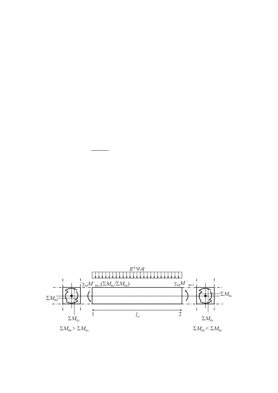
prEN 1998-1:2003 (E)
76
under: a) the transverse load acting on it in the seismic design situation and b) end
moments M
i,d
(with i=1,2 denoting the end sections of the beam), corresponding to
plastic hinge formation for positive and negative directions of seismic loading. The
plastic hinges should be taken to form at the ends of the beams or (if they form there
first) in the vertical elements connected to the joints into which the beam ends frame
(see Figure 5.1).
(2) Paragraph
(1)P of this subclause should be implemented as follows.
a) At end section i, two values of the acting shear force should be calculated, i.e. the
maximum V
Ed,max,i
and the minimum V
Ed,min,i
corresponding to the maximum positive
and the maximum negative end moments M
i,d
that can develop at ends 1 and 2 of the
beam.
b) End moments M
i,d
in (1)P and in (2) a) of this subclause may be determined as
follows:
)
,
1
min(
Rb
Rc
i
Rb,
Rd
d
i,
∑
∑
=
M
M
M
M
γ
(5.8)
where
γ
Rd
is the factor accounting for possible overstrength due to steel strain hardening,
which in the case of DCM beams may be taken as being equal to 1,0;
M
Rb,i
is the design value of the beam moment of resistance at end i in the sense of the
seismic bending moment under the considered sense of the seismic action;
ΣM
Rc
and
ΣM
Rb
are the sum of the design values of the moments of resistance of the
columns and the sum of the design values of the moments of resistance of the
beams framing into the joint, respectively (see 4.4.2.3(4)). The value of
ΣM
Rc
should correspond to the column axial force(s) in the seismic design situation for
the considered sense of the seismic action.
c) At a beam end where the beam is supported indirectly by another beam, instead of
framing into a vertical member, the beam end moment M
i,d
there may be taken as being
equal to the acting moment at the beam end section in the seismic design situation.
Figure 5.1: Capacity design values of shear forces on beams

prEN 1998-1:2003 (E)
77
5.4.2.3 Columns
(1)P In primary seismic columns the design values of shear forces shall be
determined in accordance with the capacity design rule, on the basis of the equilibrium
of the column under end moments M
i,d
(with i=1,2 denoting the end sections of the
column), corresponding to plastic hinge formation for positive and negative directions
of seismic loading. The plastic hinges should be taken to form at the ends of the beams
connected to the joints into which the column end frames, or (if they form there first) in
the columns (see Figure 5.2).
(2) End
moments
M
i,d
in (1)P of this subclause may be determined from the
following expression:
)
,
1
min(
Rc
Rb
i
Rc,
Rd
d
i,
∑
∑
=
M
M
M
M
γ
(5.9)
where
γ
Rd
is the factor accounting for overstrength due to steel strain hardening and
confinement of the concrete of the compression zone of the section, taken as
being equal to 1,1;
M
Rc,i
is the design value of the column moment of resistance at end i in the sense of
the seismic bending moment under the considered sense of the seismic action;
ΣM
Rc
and
ΣM
Rb
are as defined in 5.4.2.2(2).
(3) The
values
of
M
Rc,i
and
ΣM
Rc
should correspond to the column axial force(s) in
the seismic design situation for the considered sense of the seismic action.
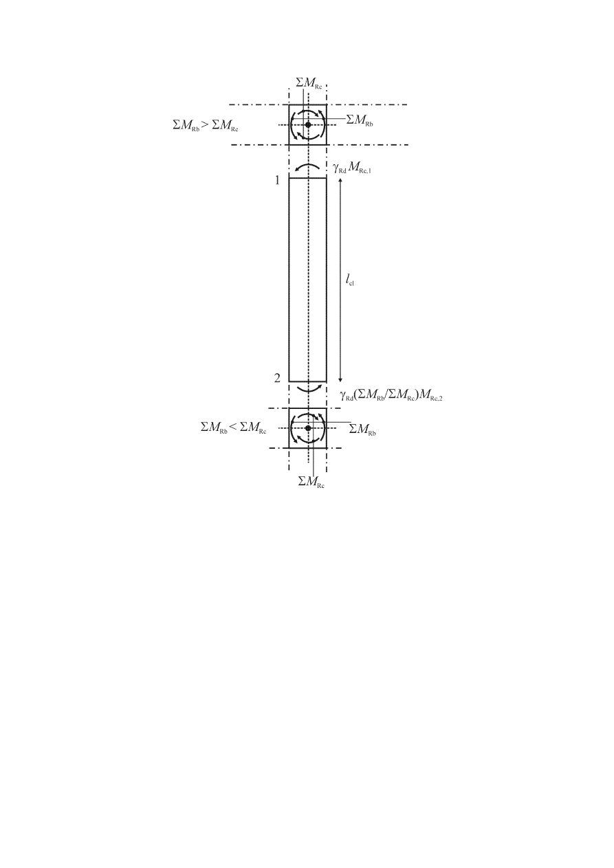
prEN 1998-1:2003 (E)
78
Figure 5.2: Capacity design shear force in columns
5.4.2.4 Special provisions for ductile walls
(1)P Uncertainties in the analysis and post-elastic dynamic effects shall be taken into
account, at least through an appropriate simplified method. If a more precise method is
not available, the rules in the following clauses for the design envelopes for bending
moments, as well as the magnification factors for shear forces, may be used.
(2)
Redistribution of seismic action effects between primary seismic walls of up to
30% is allowed, provided that the total resistance demand is not reduced. Shear forces
should be redistributed along with the bending moments, so that the in the individual
walls the ratio of bending moments to shear forces is not appreciably affected. In walls
subjected to large fluctuations of axial force, as e.g. in coupled walls, moments and
shears should be redistributed from the wall(s) which are under low compression or
under net tension, to those which are under high axial compression.
(3)
In coupled walls redistribution of seismic action effects between coupling beams
of different storeys of up to 20% is allowed, provided that the seismic axial force at the
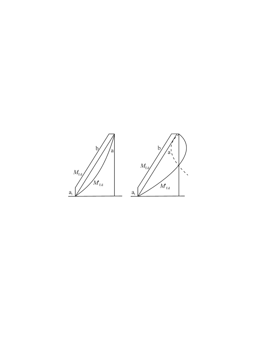
prEN 1998-1:2003 (E)
79
base of each individual wall (the resultant of the shear forces in the coupling beams) is
not affected.
(4)P Uncertainties regarding the moment distribution along the height of slender
primary seismic walls (with height to length ratio h
w
/l
w
greater than 2,0) shall be
covered.
(5)
The requirement specified in (4)P of this subclause may be satisfied by applying,
irrespective of the type of analysis used, the following simplified procedure.
The design bending moment diagram along the height of the wall should be given by an
envelope of the bending moment diagram from the analysis, vertically displaced
(tension shift). The envelope may be assumed linear, if the structure does not exhibit
significant discontinuities of mass, stiffness or resistance over its height (see Figure
5.3). The tension shift should be consistent with the strut inclination taken in the ULS
verification for shear, with a possible fan-type pattern of struts near the base, and with
the floors acting as ties.
Key
a
moment diagram from analysis
b design
envelope
a
l
tension shift
Figure 5.3: Design envelope for bending moments in slender walls
(left: wall systems; right: dual systems).
(6)P The possible increase in shear forces after yielding at the base of a primary
seismic wall, shall be taken into account.
(7)
The requirement specified in (6)P of this subclause may be satisfied if the design
shear forces are taken as being 50% higher than the shear forces obtained from the
analysis.
(8)
In dual systems containing slender walls the design envelope of shear forces in
accordance with Figure 5.4 should be used, to account for uncertainties in higher mode
effects.
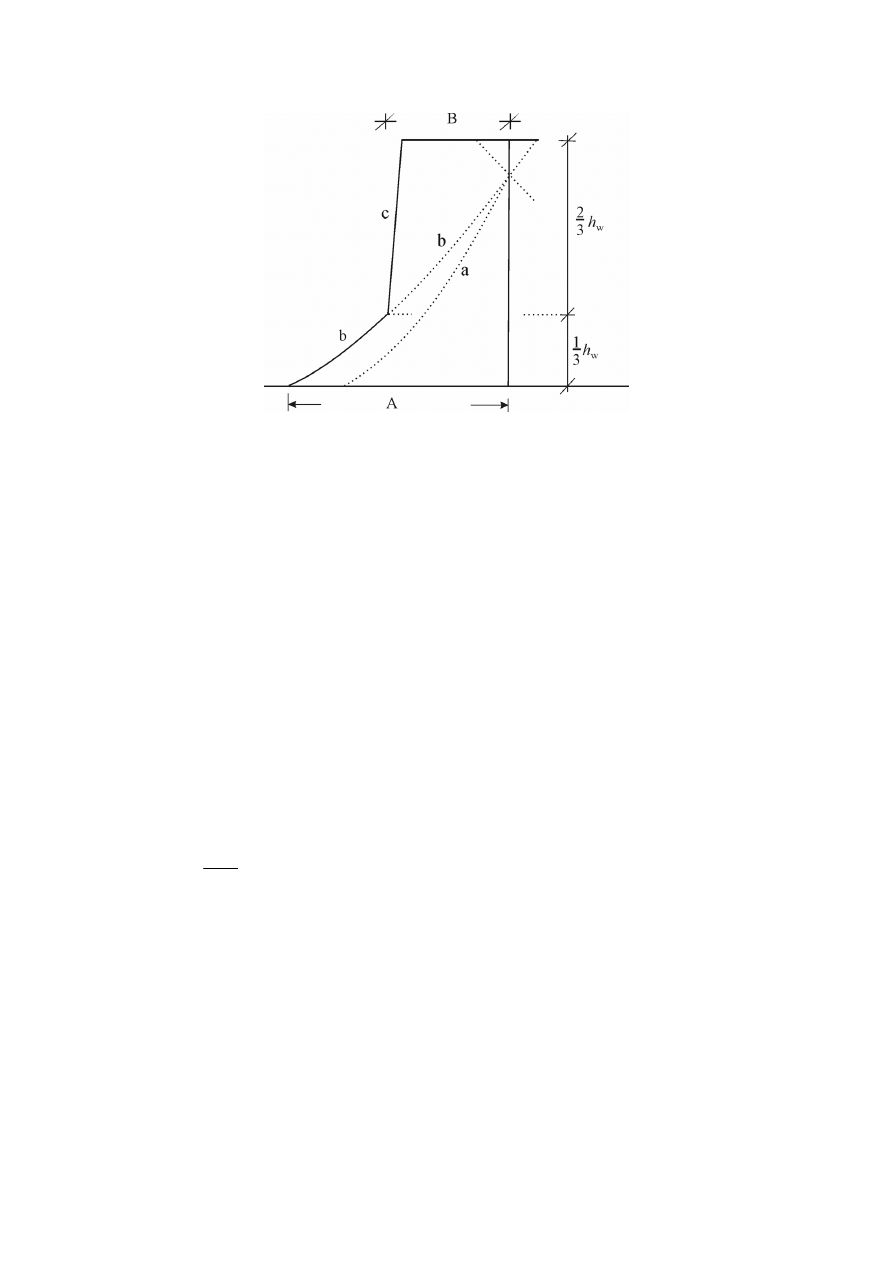
prEN 1998-1:2003 (E)
80
Key
a
shear diagram from analysis
b
magnified shear diagram
c design
envelope
A
V
wall,base
B
V
wall,top
≥ V
wall,base
/2
Figure 5.4: Design envelope of the shear forces in the walls of a dual system.
5.4.2.5 Special provisions for large lightly reinforced walls
(1)P To ensure that flexural yielding precedes attainment of the ULS in shear, the
shear force V’
Ed
from the analysis shall be increased.
(2)
The requirement in (1)P of this subclause is considered to be satisfied if at every
storey of the wall the design shear force V
Ed
is obtained from the shear force calculated
from the analysis, V’
Ed
, in accordance with the following expression:
2
1
'
Ed
Ed
+
=
q
V
V
(5.10)
(3)P The additional dynamic axial forces developed in large walls due to uplifting
from the soil, or due to the opening and closing of horizontal cracks, shall be taken into
account in the ULS verification of the wall for flexure with axial force.
(4)
Unless the results of a more precise calculation are available, the dynamic
component of the wall axial force in (3)P of this subclause may be taken as being 50%
of the axial force in the wall due to the gravity loads present in the seismic design
situation. This force should be taken to have a plus or a minus sign, whichever is most
unfavourable.
(5)
If the value of the behaviour factor q does not exceed 2,0, the effect of the
dynamic axial force in (3) and (4) of this subclause may be neglected.
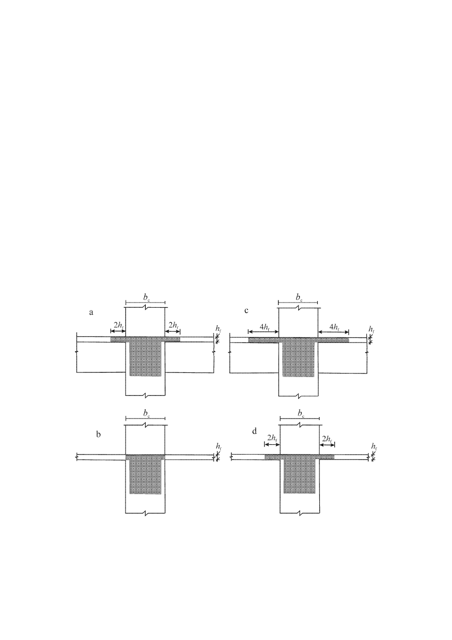
prEN 1998-1:2003 (E)
81
5.4.3 ULS verifications and detailing
5.4.3.1 Beams
5.4.3.1.1 Resistance in bending and shear
(1)
The bending and shear resistances should be computed in accordance with EN
1992-1-1:2004.
(2)
The top-reinforcement of the end cross-sections of primary seismic beams with a
T- or L-shaped section should be placed mainly within the width of the web. Only part
of this reinforcement may be placed outside the width of the web, but within the
effective flange width b
eff
.
(3)
The effective flange width b
eff
may be assumed to be as follows:
a)
for primary seismic beams framing into exterior columns, the effective flange
width b
eff
is taken, in the absence of a transverse beam, as being equal to the width b
c
of
the column (Figure 5.5b), or, if there is a transverse beam of similar depth, equal to this
width increased by 2h
f
on each side of the beam (Figure 5.5a);
b)
for primary seismic beams framing into interior columns the above widths may
be increased by 2h
f
on each side of the beam (Figure 5.5c and d).
Figure 5.5: Effective flange width b
eff
for beams framing into columns

prEN 1998-1:2003 (E)
82
5.4.3.1.2 Detailing for local ductility
(1)P The regions of a primary seismic beam up to a distance l
cr
=h
w
(where h
w
denotes
the depth of the beam) from an end cross-section where the beam frames into a beam-
column joint, as well as from both sides of any other cross-section liable to yield in the
seismic design situation, shall be considered as being critical regions.
(2)
In primary seismic beams supporting discontinued (cut-off) vertical elements,
the regions up to a distance of 2h
w
on each side of the supported vertical element should
be considered as being critical regions.
(3)P To satisfy the local ductility requirement in the critical regions of primary
seismic beams, the value of the curvature ductility factor
µ
φ
shall be at least equal to the
value given in 5.2.3.4(3).
(4)
The requirement specified in (3)P of this subclause is deemed to be satisfied, if
the following conditions are met at both flanges of the beam.
a) at the compression zone reinforcement of not less than half of the reinforcement
provided at the tension zone is placed, in addition to any compression reinforcement
needed for the ULS verification of the beam in the seismic design situation.
b) The reinforcement ratio of the tension zone
ρ does not exceed a value ρ
max
equal to:
yd
cd
d
sy,
max
0018
,
0
f
f
'
⋅
+
=
ε
µ
ρ
ρ
ϕ
(5.11)
with the reinforcement ratios of the tension zone and compression zone,
ρ and ρ', both
normalised to bd, where b is the width of the compression flange of the beam. If the
tension zone includes a slab, the amount of slab reinforcement parallel to the beam
within the effective flange width defined in 5.4.3.1.1(3) is included in
ρ.
(5)P Along the entire length of a primary seismic beam, the reinforcement ratio of the
tension zone,
ρ, shall be not less than the following minimum value ρ
min
:
=
yk
ctm
min
5
,
0
f
f
ρ
(5.12)
(6)P Within the critical regions of primary seismic beams, hoops satisfying the
following conditions shall be provided:
a) The diameter d
bw
of the hoops (in millimetres) shall be not less than 6.
b) The spacing, s, of hoops (in millimetres) shall not exceed:
s = min{h
w
/4; 24d
bw
; 225; 8d
bL
} (5.13)
where
d
bL
is the minimum longitudinal bar diameter (in millimetres); and
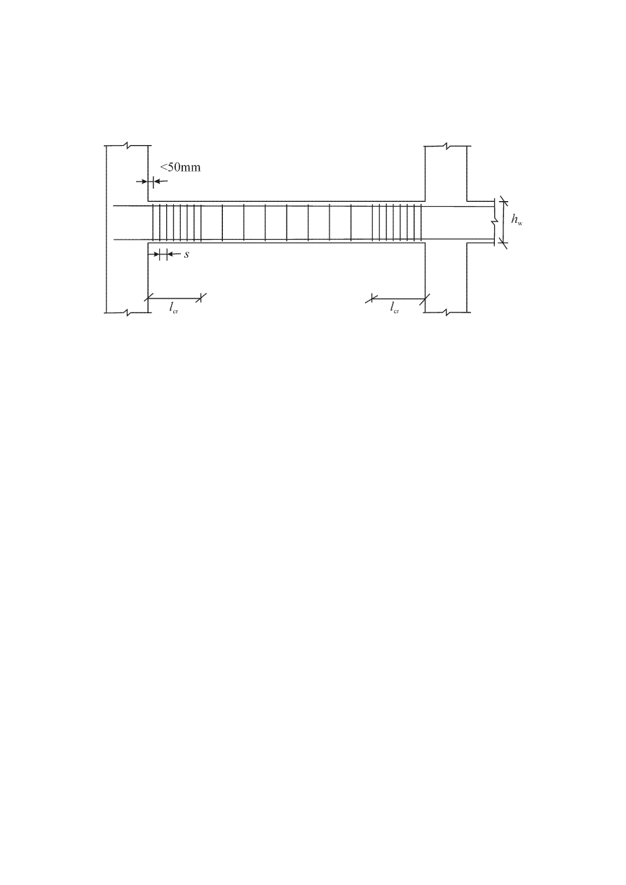
prEN 1998-1:2003 (E)
83
h
w
the beam depth (in millimetres).
c) The first hoop shall be placed not more than 50 mm from the beam end section (see
Figure 5.6).
Figure 5.6: Transverse reinforcement in critical regions of beams
5.4.3.2 Columns
5.4.3.2.1 Resistances
(1)P Flexural and shear resistance shall be computed in accordance with EN 1992-1-
1:2004, using the value of the axial force from the analysis in the seismic design
situation.
(2)
Biaxial bending may be taken into account in a simplified way by carrying out
the verification separately in each direction, with the uniaxial moment of resistance
reduced by 30%.
(3)P In primary seismic columns the value of the normalised axial force
ν
d
shall not
exceed 0,65.
5.4.3.2.2 Detailing of primary seismic columns for local ductility
(1)P The total longitudinal reinforcement ratio
ρ
l
shall be not less than 0,01 and not
more than 0,04. In symmetrical cross-sections symmetrical reinforcement should be
provided (
ρ = ρ′).
(2)P At least one intermediate bar shall be provided between corner bars along each
column side, to ensure the integrity of the beam-column joints.
(3)P The regions up to a distance l
cr
from both end sections of a primary seismic
column shall be considered as being critical regions.
(4)
In the absence of more precise information, the length of the critical region l
cr
(in
metres) may be computed from the following expression:
{
}
45
0,
;
6
/
;
max
cl
c
cr
l
h
l
=
(5.14)

prEN 1998-1:2003 (E)
84
where
h
c
is the largest cross-sectional dimension of the column (in metres); and
l
cl
is the clear length of the column (in metres).
(5)P If
l
c
/h
c
<3, the entire height of the primary seismic column shall be considered as
being a critical region and shall be reinforced accordingly.
(6)P In the critical region at the base of primary seismic columns a value of the
curvature ductility factor,
µ
φ,
should be provided, at least equal to that given in
5.2.3.4(3).
(7)P If for the specified value of
µ
φ
a concrete strain larger than
ε
cu2
=0,0035 is needed
anywhere in the cross-section, compensation for the loss of resistance due to spalling of
the concrete shall be achieved by means of adequate confinement of the concrete core,
on the basis of the properties of confined concrete in EN 1992-1-1:2004, 3.1.9.
(8)
The requirements specified in (6)P and (7)P of this subclause are deemed to be
satisfied if:
035
,
0
30
o
c
d
sy,
d
wd
−
⋅
⋅
≥
b
b
v ε
µ
αω
ϕ
(5.15)
where
ω
wd
is the mechanical volumetric ratio of confining hoops within the critical regions
⋅
=
cd
yd
wd
core
concrete
of
volume
hoops
confining
of
volume
f
f
ω
;
µ
φ
is the required value of the curvature ductility factor;
ν
d
is the normalised design axial force (
ν
d
= N
Ed
/A
c
⋅f
cd
);
ε
sy,d
is the design value of tension steel strain at yield;
h
c
is the gross cross-sectional depth (parallel to the horizontal direction in which
the value of
µ
φ
used in (6)P of this subclause applies);
h
o
is the depth of confined core (to the centreline of the hoops);
b
c
is the gross cross-sectional width;
b
o
is the width of confined core (to the centreline of the hoops);
α
is the confinement effectiveness factor, equal to
α=α
n
⋅α
s
, with:
a)
For rectangular cross-sections:
o
o
n
2
i
n
6
/
1
h
b
b
∑
−
=
α
(5.16a)
(
)(
)
o
o
s
2
/
1
2
/
1
h
s
b
s
−
−
=
α
(5.17a)
where
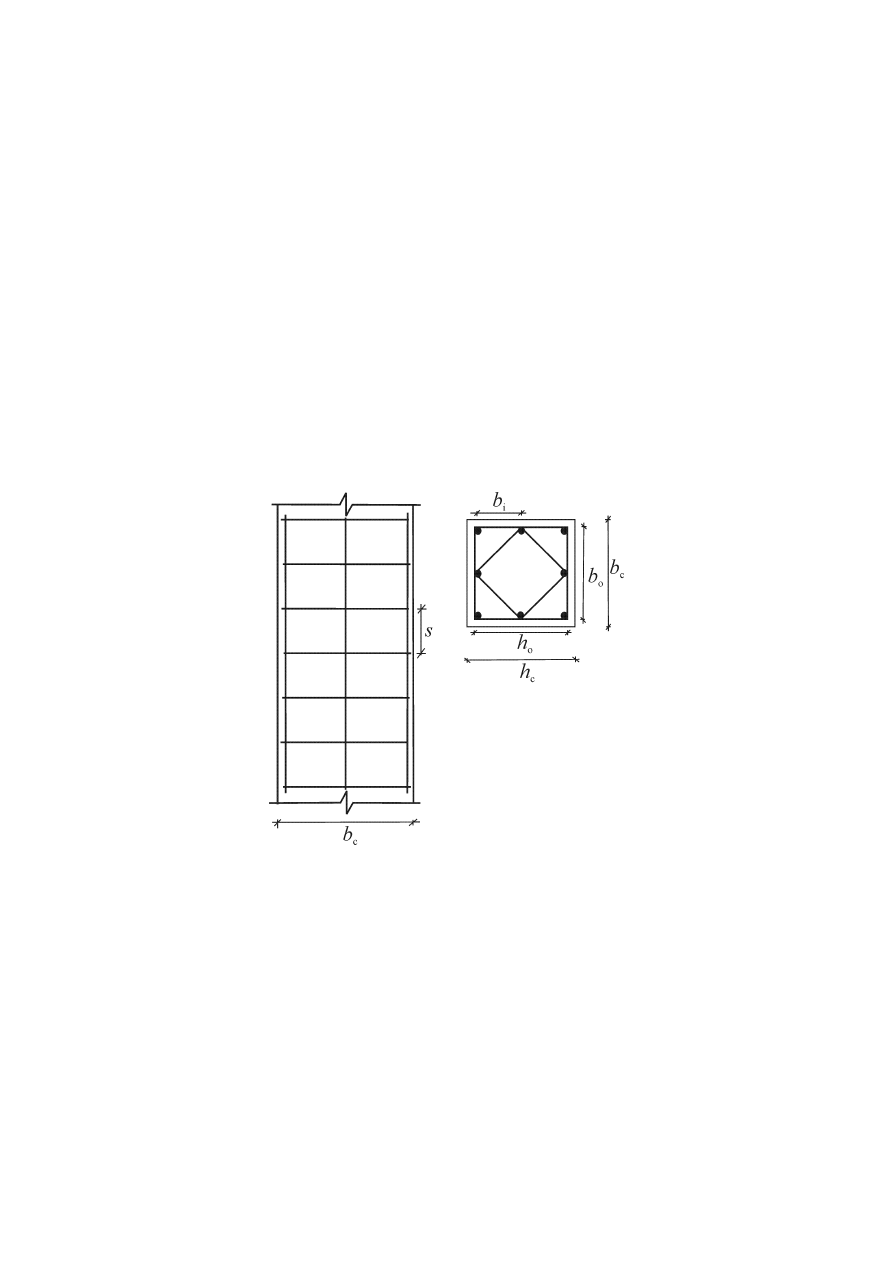
prEN 1998-1:2003 (E)
85
n
is the total number of longitudinal bars laterally engaged by hoops or cross ties;
and
b
i
is the distance between consecutive engaged bars (see Figure 5.7; also for b
o
, h
o
,
s).
b)
For circular cross-sections with hoops and diameter of confined core D
o
(to the
centreline of hoops):
1
n
=
α
(5.16b)
(
)
2
o
s
2
/
1
D
s
−
=
α
(5.17b)
c) For
circular
cross-sections with spiral reinforcement:
1
n
=
α
(5.16c)
(
)
o
s
2
/
1
D
s
−
=
α
(5.17c)
Figure 5.7: Confinement of concrete core
(9)
A minimum value of
ω
wd
equal to 0,08 should be provided within the critical
region at the base of the primary seismic columns.
(10)P Within the critical regions of the primary seismic columns, hoops and cross-ties,
of at least 6 mm in diameter, shall be provided at a spacing such that a minimum
ductility is ensured and local buckling of longitudinal bars is prevented. The hoop
pattern shall be such that the cross-section benefits from the triaxial stress conditions
produced by the hoops.
(11) The minimum conditions of (10)P of this subclause are deemed to be satisfied if
the following conditions are met.

prEN 1998-1:2003 (E)
86
a) The spacing, s, of the hoops (in millimetres) does not exceed:
s = min{b
o
/2; 175; 8d
bL
} (5.18)
where
b
o
(in millimetres) is the minimum dimension of the concrete core (to the centreline
of the hoops); and
d
bL
is the minimum diameter of the longitudinal bars (in millimetres).
b) The distance between consecutive longitudinal bars engaged by hoops or cross-ties
does not exceed 200 mm, taking into account EN 1992-1-1:2004, 9.5.3(6).
(12)P The transverse reinforcement within the critical region at the base of the primary
seismic columns may be determined as specified in EN 1992-1-1:2004, provided that
the value of the normalised axial load in the seismic design situation is less than 0,2 and
the value of the behaviour factor q used in the design does not exceed 2,0.
5.4.3.3 Beam-column
joints
(1)
The horizontal confinement reinforcement in joints of primary seismic beams
with columns should be not less than that specified in 5.4.3.2.2(8)-(11) for the critical
regions of columns, with the exception of the case listed in the following paragraph.
(2)
If beams frame into all four sides of the joint and their width is at least three-
quarters of the parallel cross-sectional dimension of the column, the spacing of the
horizontal confinement reinforcement in the joint may be increased to twice that
specified in (1) of this subclause, but may not exceed 150 mm.
(3)P At least one intermediate (between column corner bars) vertical bar shall be
provided at each side of a joint of primary seismic beams and columns.
5.4.3.4 Ductile
Walls
5.4.3.4.1 Bending and shear resistance
(1)P Flexural and shear resistances shall be computed in accordance with EN 1992-1-
1:2004, unless specified otherwise in the following paragraphs, using the value of the
axial force resulting from the analysis in the seismic design situation.
(2)
In primary seismic walls the value of the normalised axial load
ν
d
should not
exceed 0,4.
(3)P Vertical web reinforcement shall be taken into account in the calculation of the
flexural resistance of wall sections.
(4)
Composite wall sections consisting of connected or intersecting rectangular
segments (L-, T-, U-, I- or similar sections) should be taken as integral units, consisting
of a web or webs parallel or approximately parallel to the direction of the acting seismic
shear force and a flange or flanges normal or approximately normal to it. For the
calculation of flexural resistance, the effective flange width on each side of a web
should be taken to extend from the face of the web by the minimum of:

prEN 1998-1:2003 (E)
87
a) the actual flange width;
b) one-half of the distance to an adjacent web of the wall; and
c) 25% of the total height of the wall above the level considered.
5.4.3.4.2 Detailing for local ductility
(1)
The height of the critical region h
cr
above the base of the wall may be estimated
as:
[
]
6
/
max
w
w,
cr
h
l
h
=
(5.19a)
but
≥
⋅
≤
⋅
≤
storeys
7
n
for
2
storeys
6
n
for
2
s
s
w
cr
h
h
l
h
(5.19b)
where h
s
is the clear storey height and where the base is defined as the level of the
foundation or of the embedment in basement storeys with rigid diaphragms and
perimeter walls.
(2)
At the critical regions of walls a value
µ
φ
of the curvature ductility factor should
be provided, that is at least equal to that calculated from expressions (5.4), (5.5) in
5.2.3.4(3) with the basic value of the behaviour factor q
o
in these expressions replaced
by the product of q
o
times the maximum value of the ratio M
Ed
/M
Rd
at the base of the
wall in the seismic design situation, where M
Ed
is the design bending moment from the
analysis; and M
Rd
is the design flexural resistance.
(3)
Unless a more precise method is used, the value of
µ
φ
specified in (2) of this
subclause may be supplied by means of confining reinforcement within edge regions of
the cross-section, termed boundary elements, the extent of which should be determined
in accordance with (6) of this subclause. The amount of confining reinforcement should
be determined in accordance with (4) and (5) of this subclause:
(4)
For walls of rectangular cross-section, the mechanical volumetric ratio of the
required confining reinforcement
ω
wd
in boundary elements should satisfy the following
expression, with the -values of
µ
φ
as specified in (2) of this subclause:
(
)
035
,
0
30
o
c
d
sy,
d
wd
−
+
≥
b
b
ε
ω
ν
µ
αω
ν
ϕ
(5.20)
where the parameters are defined in 5.4.3.2.2(8), except
ω
ν
, which is the mechanical
ratio of vertical web reinforcement (
ω
ν
=
ρ
ν
f
yd,v
/f
cd
).
(5)
For walls with barbells or flanges, or with a section consisting of several
rectangular parts (T-, L-, I-, U-shaped sections, etc.) the mechanical volumetric ratio of
the confining reinforcement in the boundary elements may be determined as follows:

prEN 1998-1:2003 (E)
88
a)
The axial force and the web vertical reinforcement ratio shall be normalised to
h
c
b
c
f
cd
, with the width of the barbell or flange in compression taken as the cross-
sectional width b
c
(
ν
d
=N
Ed
/ h
c
b
c
f
cd
,
ω
ν
=(A
sv
/h
c
b
c
)f
yd
/ f
cd
). The neutral axis depth x
u
at
ultimate curvature after spalling of the concrete outside the confined core of the
boundary elements may be estimated as:
(
)
o
c
c
d
u
b
b
h
x
ν
ω
ν +
=
(5.21)
where b
o
is the width of the confined core in the barbell or flange. If the value of x
u
from
expression (5.21) does not exceed the depth of the barbell or flange after spalling of the
cover concrete, then the mechanical volumetric ratio of the confining reinforcement in
the barbell or flange is determined as in a) of this subclause (i.e. from expression (5.20),
5.4.3.4.2(4)), with
ν
d
,
ω
v
, b
c
and b
o
referring to the width of the barbell or flange.
b)
If the value of x
u
exceeds the depth of the barbell or flange after spalling of the
cover concrete, the general method based on: 1) the definition of the curvature ductility
factor as
µ
φ
=
φ
u
/
φ
y
, 2) the calculation of
φ
u
as
ε
cu2,c
/ x
u
and of
φ
y
as
ε
sy
/ (d - x
y
), 3)
section equilibrium for the estimation of neutral axis depths x
u
and x
y
, and 4) the
strength and ultimate strain of confined concrete, f
ck,c
and
ε
cu2,c
as a function of the
effective lateral confining stress (see EN 1992-1-1:2004, 3.1.9) may be followed. The
required confining reinforcement, if needed, and the confined wall lengths should be
calculated accordingly.
(6)
The confinement of (3)-(5) of this subclause should extend vertically over the
height h
cr
of the critical region as defined in 5.4.3.4.2(1) and horizontally along a length
l
c
measured from the extreme compression fibre of the wall up to the point where
unconfined concrete may spall due to large compressive strains. If more precise data is
not available, the compressive strain at which spalling is expected may be taken as
being equal to
ε
cu2
=0,0035. The confined boundary element may be limited extend up to
a distance of x
u
(1-
ε
cu2
/
ε
cu2,c
) from the hoop centreline near the extreme compression
fibre, with the depth of the confined compression zone x
u
at ultimate curvature
estimated from equilibrium (cf. expression (5.21) for a constant width b
o
of the confined
compression zone) and the ultimate strain
ε
cu2,c
of confined concrete estimated on the
basis of EN 1992-1-1:2004, 3.1.9 as
ε
cu2,c
=0,0035+0,1
αω
wd
(Figure 5.8). As a
minimum, the length l
c
of the confined boundary element should not be taken as being
smaller than 0,15
⋅l
w
or 1,50.b
w
.
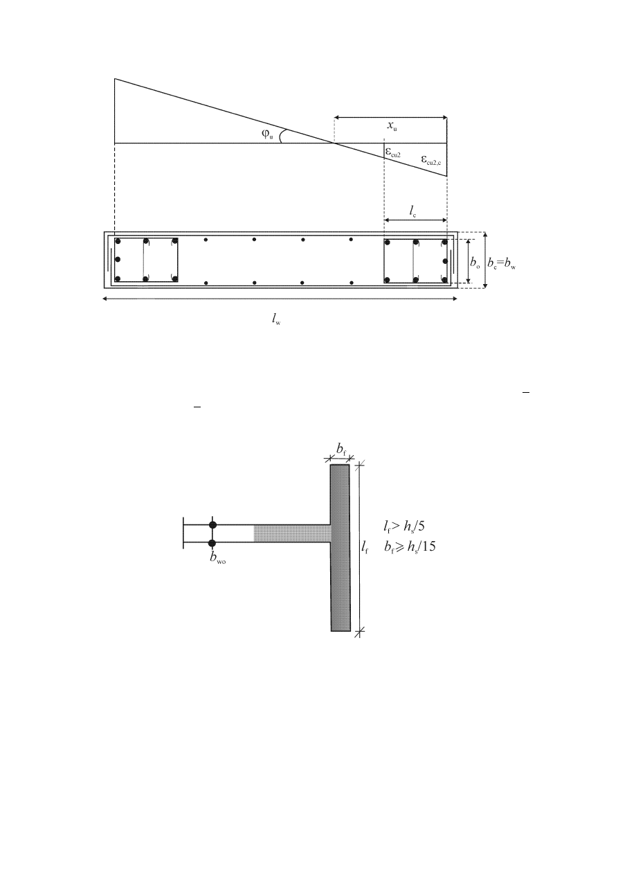
prEN 1998-1:2003 (E)
89
Figure 5.8: Confined boundary element of free-edge wall end
(top: strains at ultimate curvature; bottom: wall cross-section)
(7)
No confined boundary element is required over wall flanges with thickness b
f
>
h
s
/15 and width l
f
> h
s
/5, where h
s
denotes the clear storey height (Figure 5.9).
Nonetheless, confined boundary elements may be required at the ends of such flanges
due to out-of-plane bending of the wall .
Figure 5.9: Confined boundary elements not needed at wall ends with a large
transverse flange
(8)
The longitudinal reinforcement ratio in the boundary elements should be not less
than 0,005.
(9)
The provisions of 5.4.3.2.2(9) and (11) apply within the boundary elements of
walls. Overlapping hoops should be used, so that every other longitudinal bar is
engaged by a hoop or cross-tie.
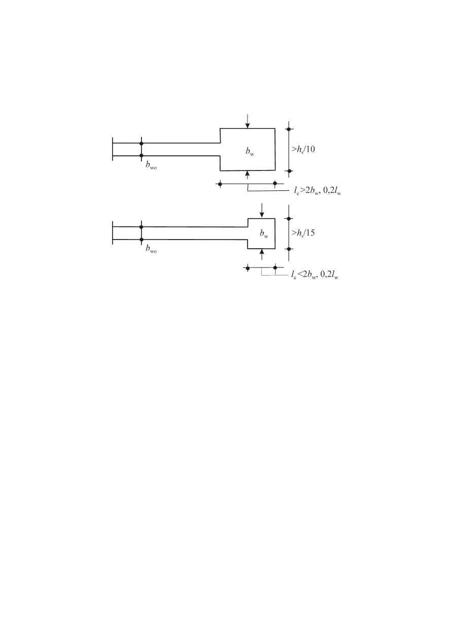
prEN 1998-1:2003 (E)
90
(10) The
thickness
b
w
of the confined parts of the wall section (boundary elements)
should not be less than 200 mm. Moreover, if the length of the confined part does not
exceed the maximum of 2b
w
and 0,2l
w
, b
w
should not be less than h
s
/15, with h
s
denoting the storey height. If the length of the confined part exceeds the maximum of
2b
w
and 0,2l
w
b
w
should not be less than h
s
/10 (See Figure 5.10).
Figure 5.10: Minimum thickness of confined boundary elements
(11) In the height of the wall above the critical region only the relevant rules of EN
1992-1-1:2004 regarding vertical, horizontal and transverse reinforcement apply.
However, in those parts of the section where under the seismic design situation the
compressive strain
ε
c
exceeds 0,002, a minimum vertical reinforcement ratio of 0,005
should be provided.
(12) The transverse reinforcement of the boundary elements of (4)-(10) of this
subclause may be determined in accordance with EN 1992-1-1:2004 alone, if one of the
following conditions is fulfilled:
a) The value of the normalised design axial force
ν
d
is not greater than 0,15; or,
b) the value of
ν
d
is not greater than 0,20 and the q-factor used in the analysis is reduced
by 15%.
5.4.3.5 Large lightly reinforced walls
5.4.3.5.1 Bending resistance
(1)P The ULS in bending with axial force shall be verified assuming horizontal
cracking, in accordance with the relevant provisions of EN 1992-1-1:2004, including
the plane sections assumption.
(2)P Normal stresses in the concrete shall be limited, to prevent out-of-plane
instability of the wall.

prEN 1998-1:2003 (E)
91
(3)
The requirement of (2)P of this subclause may be satisfied on the basis of the
rules of EN 1992-1-1:2004 for second-order effects, supplemented with other rules for
the normal stresses in the concrete if necessary.
(4)
When the dynamic axial force of 5.4.2.5(3)P and (4) is taken into account in the
ULS verification for bending with axial force, the limiting strain
ε
cu2,c
for unconfined
concrete may be increased to 0,005. A higher value may be taken into account for
confined concrete, in accordance with EN 1992-1-1:2004, 3.1.9, provided that spalling
of the unconfined concrete cover is accounted for in the verification.
5.4.3.5.2 Shear resistance
(1)
Due to the safety margin provided by the magnification of design shear forces in
5.4.2.5(1)P and (2) and because the response (including possible inclined cracking) is
deformation-controlled, wherever the value of V
Ed
from 5.4.2.5(2) is less than the design
value of the shear resistance V
Rd,c
in EN 1992-1-1:2004, 6.2.2, the minimum shear
reinforcement ratio
ρ
w,min
in the web is not required.
NOTE The value ascribed to
ρ
w,min
for use in a country may be found in its National Annex to
this document. The recommended value is the minimum value for walls in EN 1992-1-1:2004
and in its National Annex.
(2)
Wherever the condition V
Ed
≤V
Rd,c
is not fulfilled, web shear reinforcement
should be calculated in accordance with EN 1992-1-1:2004, on the basis of a variable
inclination truss model, or a strut-and-tie model, whichever is most appropriate for the
particular geometry of the wall.
(3)
If a strut-and-tie model is used, the width of the strut should take into account
the presence of openings and should not exceed 0,25l
w
or 4b
wo
, whichever is smaller.
(4)
The ULS against sliding shear at horizontal construction joints should be
verified in accordance with EN 1992-1-1:2004, 6.2.5, with the anchorage length of
clamping bars crossing the interface increased by 50% over that required by EN 1992-1-
1:2004.
5.4.3.5.3 Detailing for local ductility
(1)
Vertical bars necessary for the verification of the ULS in bending with axial
force, or for the satisfaction of any minimum reinforcement provisions, should be
engaged by a hoop or a cross-tie with a diameter of not less than 6 mm or one third of
the vertical bar diameter, d
bL
. Hoops and cross-ties should be at a vertical spacing of not
more than 100 mm or 8d
bL
, whichever is less.
(2)
Vertical bars necessary for the verification of the ULS in bending with axial
force and laterally restrained by hoops and cross-ties in accordance with (1) of this
subclause should be concentrated in boundary elements at the ends of the cross-section.
These elements should extend in the direction of the length l
w
of the wall over a length
not less than b
w
or 3b
w
σ
cm
/f
cd
, whichever is less, where
σ
cm
is the mean value of the
concrete stress in the compression zone in the ULS of bending with axial force. The
diameter of the vertical bars should not be less than 12 mm in the lower storey of the
building, or in any storey where the length l
w
of the wall is reduced over that of the

prEN 1998-1:2003 (E)
92
storey below by more than one-third of the storey height h
s
. In all other storeys the
diameter of vertical bars should not be less than 10 mm.
(3)
To avoid a change in the mode of behaviour from one controlled by flexure to
another controlled by shear, the amount of vertical reinforcement placed in the wall
section should not unnecessarily exceed the amount required for the verification of the
ULS in flexure with axial load and for the integrity of concrete.
(4)
Continuous steel ties, horizontal or vertical, should be provided: (a) along all
intersections of walls or connections with flanges; (b) at all floor levels; and (c) around
openings in the wall. As a minimum, these ties should satisfy EN 1992-1-1:2004, 9.10.
5.5 Design
for
DCH
5.5.1 Geometrical constraints and materials
5.5.1.1 Material
requirements
(1)P A concrete class lower than C 20/25 shall not be used in primary seismic
elements.
(2)P The requirement specified in paragraph 5.4.1.1(2)P applies to this subclause.
(3)P In critical regions of primary seismic elements, reinforcing steel of class C in
Table C.1 of EN 1992-1-1:2004 shall be used. Moreover, the upper characteristic (95%-
fractile) value of the actual yield strength, f
yk,0,95
, shall not exceed the nominal value by
more than 25%.
5.5.1.2 Geometrical
constraints
5.5.1.2.1 Beams
(1)P The width of primary seismic beams shall be not less than 200 mm.
(2)P The width to height ratio of the web of primary seismic beams shall satisfy
expression (5.40b) of EN 1992-1-1:2004.
(3)P Paragraph
5.4.1.2.1(1)P applies.
(4) Paragraph
5.4.1.2.1(2) applies.
(5)P Paragraph
5.4.1.2.1(3)P applies.
5.5.1.2.2 Columns
(1)P The minimum cross-sectional dimension of primary seismic columns shall be
not less than 250 mm.
(2) Paragraph
5.4.1.2.2(1) applies.

prEN 1998-1:2003 (E)
93
5.5.1.2.3 Ductile Walls
(1)P The provisions cover single primary seismic walls, as well as individual
components of coupled primary seismic walls, under in-plane action effects, with full
embedment and anchorage at their base in adequate basements and foundations, so that
the wall is not allowed to rock. In this respect, walls supported by slabs or beams are not
permitted (see also 5.4.1.2.5).
(2) Paragraph
5.4.1.2.3(1) applies.
(3)
Additional requirements apply with respect to the thickness of the confined
boundary elements of primary seismic walls, as specified in 5.5.3.4.5(8) and (9).
(4)
Random openings, not regularly arranged to form coupled walls, should be
avoided in primary seismic walls, unless their influence is either insignificant or
accounted for in analysis, dimensioning and detailing.
5.5.1.2.4 Specific rules for beams supporting discontinued vertical elements
(1)P Paragraph
5.4.1.2.5(1)P applies.
(2)P Paragraph
5.4.1.2.5(2)P applies.
5.5.2 Design action effects
5.5.2.1 Beams
(1)P Paragraph
5.4.2.1(1)P applies for the design values of bending moments and
axial forces.
(2)P Paragraph
5.4.2.2(1)P applies.
(3) Paragraph
5.4.2.2(2) applies with a value
γ
Rd
= 1,2 in expression (5.8).
5.5.2.2 Columns
(1) Paragraph
5.4.2.1(1)P (which refers also to the capacity design requirements in
5.2.3.3(2)) applies for the design values of bending moments and axial forces.
(2)P Paragraph
5.4.2.3(1)P applies.
(3) Paragraph
5.4.2.3(2) applies with a value
γ
Rd
= 1,3 in expression (5.9).
(4) Paragraph
5.4.2.3(3) applies.
5.5.2.3 Beam-column
joints
(1)P The horizontal shear acting around the core of a joint between primary seismic
beams and columns shall be determined taking into account the most adverse conditions
under seismic loading, i.e. capacity design conditions for the beams framing into the
joint and the lowest compatible values of shear forces in the framing elements.

prEN 1998-1:2003 (E)
94
(2)
Simplified expressions for the horizontal shear force acting on the concrete core
of the joints may be used as follows:
a) for interior beam-column joints:
C
yd
s2
s1
Rd
jhd
)
(
V
f
A
A
V
−
+
= γ
(5.22)
b) for exterior beam-column joints:
C
yd
s1
Rd
jhd
V
f
A
V
−
⋅
⋅
= γ
(5.23)
where
A
s1
is the area of the beam top reinforcement;
A
s2
is the area of the beam bottom reinforcement;
V
C
is the column shear force, from the analysis in the seismic design situation;
γ
Rd
is a factor to account for overstrength due to steel strain-hardening and should be
not less than 1,2.
(3)
The shear forces acting on the joints shall correspond to the most adverse
direction of the seismic action influencing the values A
s1
, A
s2
and V
C
to be used in
expressions (5.22) and (5.23).
5.5.2.4 Ductile
Walls
5.5.2.4.1 Special provisions for in-plane slender walls
(1)P Paragraph
5.4.2.4(1)P applies.
(2) Paragraph
5.4.2.4(2) applies.
(3) Paragraph
5.4.2.4(3) applies.
(4)P Paragraph
5.4.2.4(4)P applies.
(5) Paragraph
5.4.2.4(5) applies.
(6)P Paragraph
5.4.2.4(6)P applies.
(7)
The requirement of (6)P is deemed to be satisfied if the following simplified
procedure is applied, incorporating the capacity design rule:
The design shear forces V
Ed
should be derived in accordance with the expression:
'
Ed
Ed
V
V
⋅
= ε
(5.24)
where
V’
Ed
is the shear force from the analysis;

prEN 1998-1:2003 (E)
95
ε
is the magnification factor, calculated from expression (5.25), but not less than
1,5:
( )
( )
q
T
S
T
S
,
M
M
q
q
≤
+
⋅
⋅
=
2
1
e
C
e
2
Ed
Rd
Rd
1
0
γ
ε
(5.25)
where
q
is the behaviour factor used in the design;
M
Ed
is the design bending moment at the base of the wall;
M
Rd
is the design flexural resistance at the base of the wall;
γ
Rd
is the factor to account for overstrength due to steel strain-hardening; in the
absence of more precise data,
γ
Rd
may be taken equal to 1,2;
T
1
is the fundamental period of vibration of the building in the direction of shear
forces V
Ed
;
T
C
is the upper limit period of the constant spectral acceleration region of the
spectrum (see 3.2.2);
S
e
(T) is the ordinate of the elastic response spectrum (see 3.2.2).
(8)
The provisions of 5.4.2.4(8) apply to slender walls of DCH.
5.5.2.4.2 Special provisions for squat walls
(1)P In primary seismic walls with a height to length ratio, h
w
/l
w
, not greater than 2,0,
there is no need to modify the bending moments from the analysis. Shear magnification
due to dynamic effects may also be neglected.
(2)
The shear force V'
Ed
from the analysis should be increased as follows:
'
Ed
'
Ed
Ed
Rd
Rd
Ed
)
(
V
q
V
M
M
V
⋅
≤
⋅
⋅
= γ
(5.26)
(see 5.5.2.4.1(7) for definitions and values of the variables).
5.5.3 ULS verifications and detailing
5.5.3.1 Beams
5.5.3.1.1 Resistance in bending
(1)P The bending resistance shall be computed in accordance with EN 1992-1-
1:2004.
(2) Paragraph
5.4.3.1.1(2) applies.
(3) Paragraph
5.4.3.1.1(3) applies.

prEN 1998-1:2003 (E)
96
5.5.3.1.2 Shear resistance
(1)P The shear resistance computations and verifications shall be carried out in
accordance with EN 1992-1-1:2004, unless specified otherwise in the following
paragraphs.
(2)P In the critical regions of primary seismic beams, the strut inclination
θ in the
truss model shall be 45
o
.
(3)
With regard to the arrangement of shear reinforcement within the critical region
at an end of a primary seismic beam where the beam frames into a column, the
following cases should be distinguished, depending on the algebraic value of the ratio
ζ = V
Ed,min
/V
Ed,max
between the minimum and maximum acting shear forces, as derived
in accordance with 5.5.2.1(3).
a) If
ζ ≥ -0,5, the shear resistance provided by the reinforcement should be computed in
accordance with EN 1992-1-1:2004.
b) If
ζ <-0,5, i.e. when an almost full reversal of shear forces is expected, then:
i) if
(
)
d
b
f
V
⋅
⋅
⋅
+
≤
w
ctd
max
E
2
ζ
(5.27)
where f
ctd
is the design value of the concrete tensile strength from EN 1992-1-1:2004,
the same rule as in a) of this paragraph applies.
ii) if
|V
E
|
max
exceeds the limit value in expression (5.27), inclined reinforcement should
be provided in two directions, either at
±45
o
to the beam axis or along the two diagonals
of the beam in elevation, and half of
|V
E
|
max
should be resisted by stirrups and half by
inclined reinforcement;
− In such a case, the verification is carried out by means of the condition:
0,5
α
cos
2
yd
s
Emax
⋅
⋅
≤
f
A
V
(5.28)
where
A
s
is the area of the inclined reinforcement in one direction, crossing the potential
sliding plane (i.e. the beam end section);
α
is the angle between the inclined reinforcement and the beam axis (normally
α =
45
o
, or tan
α ≈ (d-d’)/l
b
).
5.5.3.1.3 Detailing for local ductility
(1)P The regions of a primary seismic beam up to a distance l
cr
=1.5h
w
(where h
w
denotes the height of the beam) from an end cross-section where the beam frames into a
beam-column joint, as well as from both sides of any other cross-section likely to yield
in the seismic design situation, shall be considered critical regions.
(2) Paragraph
5.4.3.1.2(2) applies.
(3)P Paragraph
5.4.3.1.2(3)P applies.

prEN 1998-1:2003 (E)
97
(4) Paragraph
5.4.3.1.2(4) applies.
(5)P To satisfy the necessary ductility conditions, along the entire length of a primary
seismic beam the following conditions shall be satisfied:
a) paragraph 5.4.3.1.2(5)P shall be satisfied
b) at least two high bond bars with d
b
= 14 mm shall be provided both at the top and the
bottom of the beam that run along the entire length of the beam;
c) one quarter of the maximum top reinforcement at the supports shall run along the
entire beam length.
(6)P 5.4.3.1.2(6)P applies with expression (5.13) replaced by the following:
s=min{h
w
/4; 24d
bw
; 175; 6d
bL
}. (5.29)
5.5.3.2 Columns
5.5.3.2.1 Resistances
(1)P Paragraph
5.4.3.2.1(1)P applies.
(2) Paragraph
5.4.3.2.1(2) applies.
(3)P In primary seismic columns the value of the normalised axial force
ν
d
shall not
exceed 0,55.
5.5.3.2.2 Detailing for local ductility
(1)P Paragraph
5.4.3.2.2(1)P applies.
(2)P Paragraph
5.4.3.2.2(2)P applies.
(3)P Paragraph
5.4.3.2.2(3)P applies.
(4)
In the absence of more precise information, the length of the critical region l
cr
may be computed as follows (in metres):
{
}
6
0,
;
6
/
;
5
,
1
max
cl
c
cr
l
h
l
=
(5.30)
where
h
c
is the largest cross-sectional dimension of the column (in metres); and
l
cl
is its clear length (in metres).
(5)P Paragraph
5.4.3.2.2(5)P applies.
(6)P Paragraph
5.4.3.2.2(6)P applies.
(7)
The detailing of critical regions above the base of the column should be based
on a minimum value of the curvature ductility factor
µ
φ
(see 5.2.3.4) obtained from

prEN 1998-1:2003 (E)
98
5.2.3.4(3). Wherever a column is protected against plastic hinging by the capacity
design procedure of 4.4.2.3(4) (i.e. where expression (4.29) is satisfied), the value q
o
in
expressions (5.4) and (5.5) may be substituted by 2/3 of the value of q
o
applying in a
direction parallel to the cross-sectional depth h
c
of the column.
(8)P Paragraph
5.4.3.2.2(7)P applies.
(9)
The requirements of (6)P, (7) and (8)P of this subclause are deemed to be
satisfied, if 5.4.3.2.2(8) is satisfied with the values of
µ
φ
specified in (6)P and (7) of this
subclause.
(10) The minimum value of
ω
wd
to be provided is 0,12 within the critical region at
the base of the column, or 0,08 in all column critical regions above the base.
(11)P Paragraph 5.4.3.2.2(10)P applies.
(12) The
minimal
conditions
of
(11)P of this subclause are deemed to be satisfied if
all of the following requirements are met.
a) The diameter d
bw
of the hoops is at least equal to
ydw
ydL
max
bL
bw
/
4
,
0
f
f
d
d
,
⋅
⋅
≥
(5.31)
b) The spacing s of hoops (in millimetres) does not exceed:
{
}
bL
o
6
;
125
;
3
/
min
d
b
s
=
(5.32)
where
b
o
(in millimetres) is the minimum dimension of the concrete core (to the inside of
the hoops); and
d
bL
is the the minimum diameter of the longitudinal bars (in millimetres).
c) The distance between consecutive longitudinal bars restrained by hoops or cross-ties
does not exceed 150 mm.
(13)P In the lower two storeys of buildings, hoops in accordance with (11)P and (12)
of this subclause shall be provided beyond the critical regions for an additional length
equal to half the length of these regions.
(14) The amount of longitudinal reinforcement provided at the base of the bottom
storey column (i.e. where the column is connected to the foundation) should be not less
than that provided at the top.
5.5.3.3 Beam-column
joints
(1)P The diagonal compression induced in the joint by the diagonal strut mechanism
shall not exceed the compressive strength of concrete in the presence of transverse
tensile strains.

prEN 1998-1:2003 (E)
99
(2)
In the absence of a more precise model, the requirement of (1)P of this subclause
may be satisfied by means of the subsequent rules.
a) At interior beam-column joints the following expression should be satisfied:
c
j
d
cd
jhd
1
h
b
f
V
η
ν
η
−
≤
(5.33)
where
η = 0,6(1-f
ck
/250);
ν
d
is the normalised axial force in the column above the joint; and
f
ck
is given in MPa.
b) At exterior beam-column joints:
V
jhd
should be less than 80% of the value given by the right-hand-side of expression
(5.33) where:
V
jhd
is given by expressions (5.22) and (5.23) respectively;
and the effective joint width b
j
is:
a) if b
c
> b
w
:
(
)
{
}
c
w
c
j
5
,
0
;
min
h
b
b
b
⋅
+
=
; (5.34a)
b) if b
c
< b
w
:
(
)
{
}
c
c
w
j
5
,
0
;
min
h
b
b
b
⋅
+
=
(5.34b)
(3)
Adequate confinement (both horizontal and vertical) of the joint should be
provided, to limit the maximum diagonal tensile stress of concrete max
σ
ct
to f
ctd
. In the
absence of a more precise model, this requirement may be satisfied by providing
horizontal hoops with a diameter of not less than 6 mm within the joint, such that:
ctd
cd
d
ctd
2
jc
j
jhd
jw
j
ywd
sh
ν
f
f
f
h
b
V
h
b
f
A
−
+
⋅
≥
⋅
⋅
(5.35)
where
A
sh
is the total area of the horizontal hoops;
V
jhd
is as defined in expressions (5.23) and (5.24);
h
jw
is the distance between top of the beam and the reinforcement at the bottom of
the beam;
h
jc
is the distance between extreme layers of column reinforcement;
b
j
is as defined in expression (5.34);
ν
d
is the normalised design axial force of the column above (
ν
d
=N
Ed
/A
c
⋅f
cd
);

prEN 1998-1:2003 (E)
100
f
ctd
is the design value of the tensile strength of concrete, in accordance with EN
1992-1-1:2004.
(4)
As an alternative to the rule specified in (3) of this subclause, integrity of the
joint after diagonal cracking may be ensured by horizontal hoop reinforcement. To this
end the following total area of horizontal hoops should be provided in the joint.
a) In interior joints:
A
sh
f
ywd
≥ γ
Rd
(A
s1
+A
s2
) f
yd
(1-0,8
ν
d
) (5.36a)
b) In exterior joints:
A
sh
f
ywd
≥ γ
Rd
A
s2
f
yd
(1-0,8
ν
d
) (5.36b)
where
γ
Rd
is equal to 1,2 (cf 5.5.2.3(2)) and the normalised axial force
ν
d
refers to the
column above the joint in expression (5.36a), or to the column below the joint in
expression (5.36b).
(5)
The horizontal hoops calculated as in (3) and (4) of this subclause should be
uniformly distributed within the depth h
jw
between the top and bottom bars of the beam.
In exterior joints they should enclose the ends of beam bars bent toward the joint.
(6)
Adequate vertical reinforcement of the column passing through the joint should
be provided, so that:
( )
(
)
jw
jc
sh
i
sv,
/
2/3
h
h
A
A
⋅
⋅
≥
(5.37)
where A
sh
is the required total area of the horizontal hoops in accordance with (3) and
(4) of this subclause and A
sv,i
denotes the total area of the intermediate bars placed in the
relevant column faces between corner bars of the column (including bars contributing to
the longitudinal reinforcement of columns).
(7)
5.4.3.3(1) applies.
(8)
5.4.3.3(2) applies.
(9)P 5.4.3.3(3)P applies.
5.5.3.4 Ductile
Walls
5.5.3.4.1 Bending resistance
(1)P The bending resistance shall be evaluated and verified as for columns, under the
most unfavourable axial force for the seismic design situation.
(2)
In primary seismic walls the value of the normalised axial force
ν
d
should not
exceed 0,35.
5.5.3.4.2 Diagonal compression failure of the web due to shear
(1)
The value of V
Rd,max
may be calculated as follows:

prEN 1998-1:2003 (E)
101
a) outside the critical region:
as in EN 1992-1-1:2004, with the length of the internal lever arm, z, equal to 0,8l
w
and
the inclination of the compression strut to the vertical, tan
θ, equal to 1,0.
b) in the critical region:
40% of the value outside the critical region.
5.5.3.4.3 Diagonal tension failure of the web due to shear
(1)P The calculation of web reinforcement for the ULS verification in shear shall take
into account the value of the shear ratio
α
s
= M
Ed
/(V
Ed
l
w
). The maximum value of
α
s
in
a storey should be used for the ULS verification of the storey in shear.
(2)
If the ratio
α
s
> 2,0, the provisions of in EN 1992-1-1:2004 6.2.3(1)-(7) apply,
with the values of z and tan
θ taken as in 5.5.3.4.2(1) a).
(3) If
α
s
< 2,0 the following provisions apply:
a) the horizontal web bars should satisfy the following expression (see EN 1992-1-
1:2004, 6.2.3(8)):
w
s
wo
h
yd,
h
c
Rd,
Ed
ρ
75
,
0
l
α
b
f
V
V
+
≤
(5.38)
where
ρ
h
is the reinforcement ratio of horizontal web bars (
ρ
h
=A
h
/(b
wo
⋅s
h
));
f
yd,h
is the design value of the yield strength of the horizontal web reinforcement;
V
Rd,c
is the design value of the shear resistance for members without shear
reinforcement, in accordance to EN 1992-1-1:2004,
In the critical region of the wall V
Rd,c
should be equal to 0 if the axial force N
Ed
is
tensile.
b) Vertical web bars, anchored and spliced along the height of the wall in accordance
with EN 1992-1-1:2004, should be provided to satisfy the condition:
Ed
wo
yd,
v
wo
h
yd,
h
min N
z
b
f
z
b
f
+
≤
ν
ρ
ρ
(5.39)
where
ρ
v
is the reinforcement ratio of vertical web bars (
ρ
v
=A
v
/b
wo
⋅s
v
);
f
yd, v
is the design value of the yield strength of the vertical web reinforcement;
and where the axial force N
Ed
is positive when compressive.
(4)
Horizontal web bars should be fully anchored at the ends of the wall section, e.g.
through 90
o
or 135
o
hooks.

prEN 1998-1:2003 (E)
102
(5)
Horizontal web bars in the form of elongated closed or fully anchored stirrups
may also be assumed to fully contribute to the confinement of the boundary elements of
the wall.
5.5.3.4.4 Sliding shear failure
(1)P At potential sliding shear planes (for example, at construction joints) within
critical regions the following condition shall be satisfied:
V
Ed
< V
Rd, S
where V
Rd,S
is the design value of the shear resistance against sliding.
(2)
The value of V
Rd, S
may be as follows:
fd
id
dd
S
Rd,
V
V
V
V
+
+
=
(5.40)
with:
⋅
⋅
⋅
⋅
⋅
=
sj
yd
yd
cd
sj
dd
25
,
0
3
,
1
min
A
f
f
f
A
V
Σ
Σ
(5.41)
ϕ
Σ
cos
yd
si
id
⋅
⋅
=
f
A
V
(5.42)
(
)
[
]
⋅
⋅
⋅
⋅
+
⋅
+
⋅
⋅
=
wo
w
cd
Ed
Ed
yd
sj
f
fd
5
,
0
/
min
b
l
ξ
f
η
z
M
ξ
N
f
A
Σ
µ
V
(5.43)
where
V
dd
is the dowel resistance of the vertical bars;
V
id
is the shear resistance of inclined bars (at an angle
ϕ to the potential sliding
plane, e.g. construction joint);
V
fd
is the friction resistance;
µ
f
is the concrete-to-concrete friction coefficient under cyclic actions, which may
be assumed equal to 0,6 for smooth interfaces and to 0,7 for rough ones, as
defined in EN 1992-1-1:2004, 6.2.5;
z
is the length of the internal lever arm;
ξ
is the normalised neutral axis depth;
ΣA
sj
is the sum of the areas of the vertical bars of the web or of additional bars
arranged in the boundary elements specifically for resistance against sliding;
ΣA
si
is the sum of the areas of all inclined bars in both directions; large diameter bars
are recommended for this purpose;
η = 0,6 (1-f
ck
(MPa)/250) (5.44)
N
Ed
is assumed to be positive when compressive.

prEN 1998-1:2003 (E)
103
(3)
For squat walls the following should be satisfied :
a) at the base of the wall V
id
should be greater than V
Ed
/2;
b) at higher levels V
id
should be greater than V
Ed
/4.
(4)
Inclined bars should be fully anchored on both sides of potential sliding
interfaces and should cross all sections of the wall within a distance of 0,5
⋅l
w
or 0,5
⋅h
w,
whichever is smaller, above the critical base section.
(5)
Inclined bars lead to an increase of the bending resistance at the base of the wall,
which should be taken into account whenever the acting shear V
Ed
is computed in
accordance with the capacity design rule (see 5.5.2.4.1(6)P and (7) and 5.5.2.4.2(2)).
Two alternative methods may be used.
a) The increase of bending resistance
∆M
Rd
, to be used in the calculation of V
Ed
, may be
estimated as:
i
yd
si
Rd
sin
2
1
l
f
A
M
⋅
⋅
⋅
⋅
=
ϕ
Σ
∆
(5.45)
where
l
i
is the distance between centrelines of the two sets of inclined bars, placed at an
angle of
±φ to the potential sliding plane, measured at the base section;
and the other symbols are as in expression (5.42).
b) An acting shear V
Ed
may be computed disregarding the effect of the inclined bars. In
expression (5.42) V
id
is the net shear resistance of the inclined bars (i.e. the actual shear
resistance reduced by the increase of the acting shear). Such net shear resistance of the
inclined bars against sliding may be estimated as:
(
)
[
]
w
s
i
yd
si
id
/
sin
5
,
0
cos
l
l
f
A
V
⋅
⋅
⋅
−
⋅
⋅
=
α
ϕ
ϕ
Σ
(5.46)
5.5.3.4.5 Detailing for local ductility
(1) Paragraph
5.4.3.4.2(1) applies.
(2) Paragraph
5.4.3.4.2(2) applies.
(3) Paragraph
5.4.3.4.2(3) applies.
(4) Paragraph
5.4.3.4.2(4) applies.
(5) Paragraph
5.4.3.4.2(5) applies.
(6) Paragraph
5.4.3.4.2(6) applies.
(7) Paragraph
5.4.3.4.2(8) applies.
(8) Paragraph
5.4.3.4.2(10) applies.
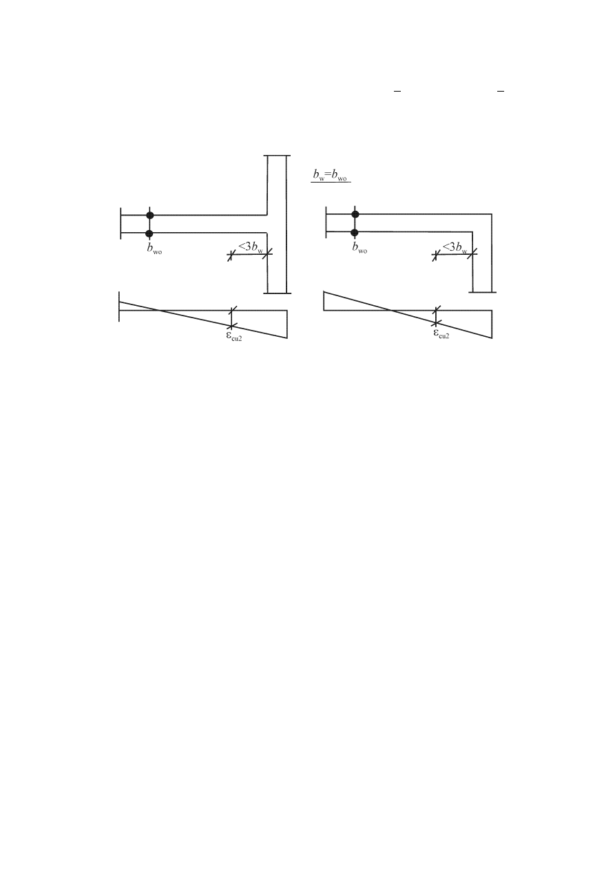
prEN 1998-1:2003 (E)
104
(9)
If the wall is connected to a flange with thickness b
f
> h
s
/15 and width l
f
> h
s
/5
(where h
s
denotes the clear storey height), and the confined boundary element needs to
extend beyond the flange into the web for an additional length of up to 3b
wo
, then the
thickness b
w
of the boundary element in the web should only follow the provisions in
5.4.1.2.3(1) for b
wo
(Figure 5.11).
Figure 5.11: Minimum thickness of confined boundary elements in DCH walls with
large flanges
(10) Within the boundary elements of walls the requirements specified in
5.5.3.2.2(12) apply and there should be a minimum value of
ω
wd
of 0,12. Overlapping
hoops should be used, so that every other longitudinal bar is engaged by a hoop or
cross-tie.
(11) Above the critical region boundary elements should be provided for one more
storey, with at least half the confining reinforcement required in the critical region.
(12) 5.4.3.4.2(11) applies.
(13)P Premature web shear cracking of walls shall be prevented, by providing a
minimum amount of web reinforcement:
ρ
h,min
=
ρ
v,min
= 0,002.
(14) The web reinforcement should be provided in the form of two grids (curtains) of
bars with the same bond characteristics, one at each face of the wall. The grids should
be connected through cross-ties spaced at about 500 mm.
(15) Web reinforcement should have a diameter of not less than 8 mm, but not
greater than one-eighth of the width b
wo
of the web. It should be spaced at not more than
250 mm or 25 times the bar diameter, whichever is smaller.
(16) To counterbalance the unfavourable effects of cracking along cold joints and the
associated uncertainties, a minimum amount of fully anchored reinforcement should be
provided across such joints. The minimum ratio of this reinforcement,
ρ
min
, necessary to
re-establish the resistance of uncracked concrete against shear, is:

prEN 1998-1:2003 (E)
105
(
)
(
)
+
⋅
−
⋅
≥
0025
,
0
/
5
,
1
1
/
3
,
1
yd
cd
yd
w
Ed
ctd
min
f
f
f
A
N
f
ρ
(5.47)
where A
w
is the total horizontal cross-sectional area of the wall and N
Ed
shall be positive
when compressive.
5.5.3.5 Coupling elements of coupled walls
(1)P Coupling of walls by means of slabs shall not be taken into account, as it is not
effective.
(2)
The provisions of 5.5.3.1 may only be applied to coupling beams, if either one
of the following conditions is fulfilled:
a) Cracking in both diagonal directions is unlikely. An acceptable application rule is:
d
b
f
V
w
ctd
Ed
≤
(5.48)
b) A prevailing flexural mode of failure is ensured. An acceptable application rule is:
l/h > 3.
(3)
If neither of the conditions in (2) is met, the resistance to seismic actions should
be provided by reinforcement arranged along both diagonals of the beam, in accordance
with the following (see Figure 5.12):
a) It should be ensured that the following expression is satisfied:
α
sin
2
yd
si
Ed
⋅
⋅
⋅
≤
f
A
V
(5.49)
where
V
Ed
is the design shear force in the coupling element (V
Ed
= 2
⋅M
Ed
/l);
A
si
is the total area of steel bars in each diagonal direction;
α
is the angle between the diagonal bars and the axis of the beam.
b) The diagonal reinforcement should be arranged in column-like elements with side
lengths at least equal to 0,5b
w
; its anchorage length should be 50% greater than that
required by EN 1992-1-1:2004.
c) Hoops should be provided around these column-like elements to prevent buckling of
the longitudinal bars. The provisions of 5.5.3.2.2(12) apply for the hoops..
d) Longitudinal and transverse reinforcement should be provided on both lateral faces
of the beam, meeting the minimum requirements specified in EN 1992-1-1:2004 for
deep beams. The longitudinal reinforcement should not be anchored in the coupled
walls and should only extend into them by 150 mm.
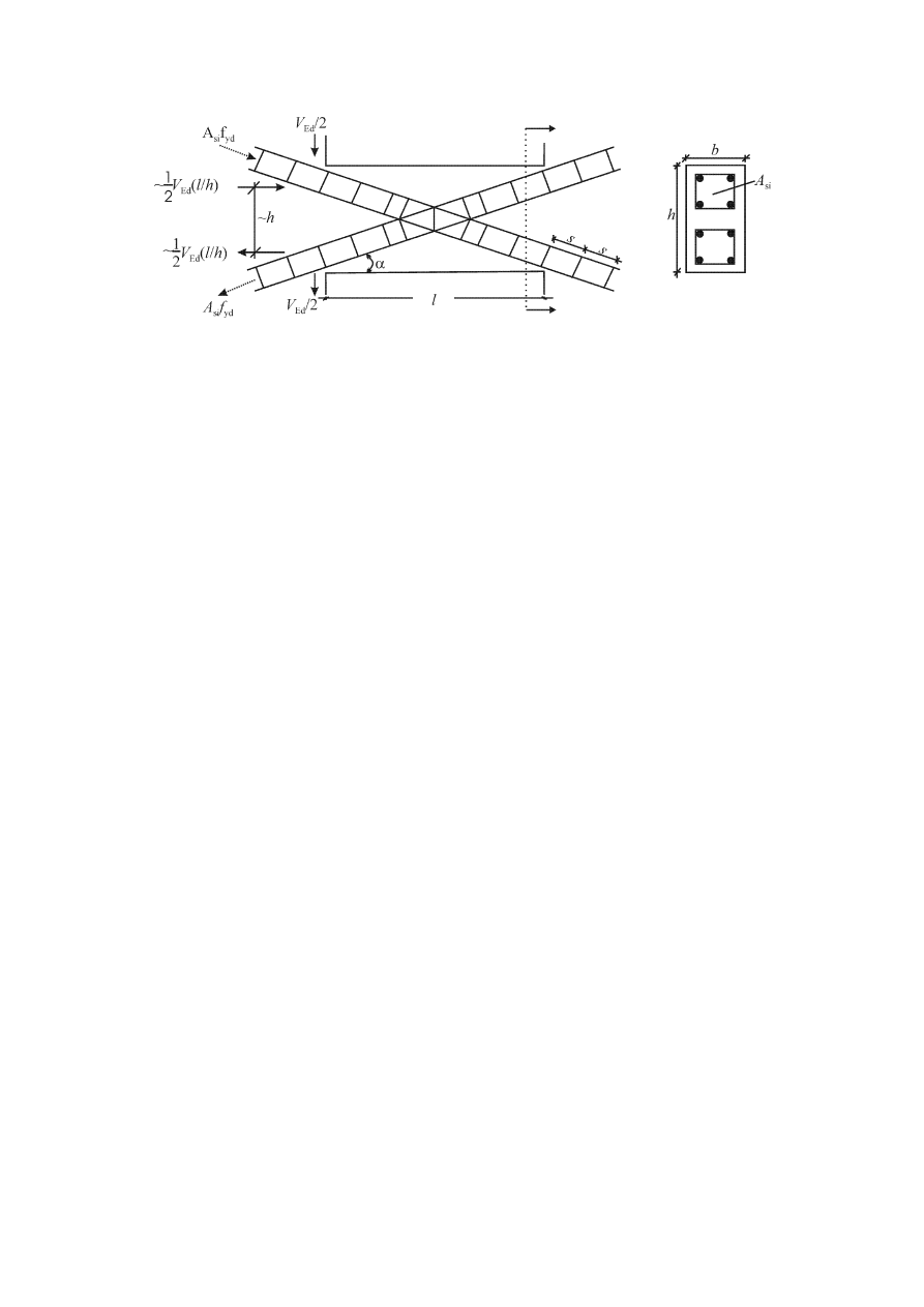
prEN 1998-1:2003 (E)
106
Figure 5.12: Coupling beams with diagonal reinforcement
5.6 Provisions for anchorages and splices
5.6.1 General
(1)P EN 1992-1-1:2004, Section 8 for the detailing of reinforcement applies, with the
additional rules of the following sub-clauses.
(2)P For hoops used as transverse reinforcement in beams, columns or walls, closed
stirrups with 135° hooks and extensions of length 10d
bw
shall be used.
(3)P In DCH structures the anchorage length of beam or column bars anchored within
beam-column joints shall be measured from a point on the bar at a distance 5d
bL
inside
the face of the joint, to take into account the yield penetration due to cyclic post-elastic
deformations (for a beam example, see Figure 5.13a).
5.6.2 Anchorage of reinforcement
5.6.2.1 Columns
(1)P When calculating the anchorage or lap length of column bars which contribute to
the flexural strength of elements in critical regions, the ratio of the required area of
reinforcement over the actual area of reinforcement A
s,req
/A
s,prov
shall be assumed to be
1.
(2)P If, under the seismic design situation, the axial force in a column is tensile, the
anchorage lengths shall be increased to 50% longer than those specified in EN 1992-1-
1:2004.
5.6.2.2 Beams
(1)P The part of beam longitudinal reinforcement bent in joints for anchorage shall
always be placed inside the corresponding column hoops.
(2)P To prevent bond failure the diameter of beam longitudinal bars passing through
beam-column joints, d
bL
, shall be limited in accordance with the following expressions:
a) for interior beam-column joints:

prEN 1998-1:2003 (E)
107
max
D
d
yd
Rd
ctm
c
bL
/
75
.
0
1
8
,
0
1
5
,
7
ρ
ρ
ν
γ
'
k
f
f
h
d
⋅
+
⋅
+
⋅
⋅
⋅
≤
(5.50a)
b) for exterior beam-column joints:
(
)
d
yd
Rd
ctm
c
bL
8
,
0
1
5
,
7
ν
γ
⋅
+
⋅
⋅
⋅
≤
f
f
h
d
(5.50b)
where
h
c
is the width of the column parallel to the bars;
f
ctm
is the mean value of the tensile strength of concrete;
f
yd
is the design value of the yield strength of steel;
ν
d
is the normalised design axial force in the column, taken with its minimum value
for the seismic design situation (
ν
d
= N
Ed
/f
cd
·A
c
);
k
D
is the factor reflecting the ductility class equal to 1 for DCH and to 2/3 for
DCM;
ρ'
is the compression steel ratio of the beam bars passing through the joint;
ρ
max
is the maximum allowed tension steel ratio (see 5.4.3.1.2(4) and 5.5.3.1.3(4));
γ
Rd
is the model uncertainty factor on the design value of resistances, taken as being
equal to1,2 or 1,0 respectively for DCH or DCM (due to overstrength owing to
strain-hardening of the longitudinal steel in the beam).
The limitations above (expressions (5.50)) do not apply to diagonal bars crossing joints.
(3)
If the requirement specified in (2)P of this clause cannot be satisfied in exterior
beam-column joints because the depth, h
c,
of the column parallel to the bars is too
shallow, the following additional measures may be taken, to ensure anchorage of the
longitudinal reinforcement of beams.
a) The beam or slab may be extended horizontally in the form of exterior stubs (see
Figure 5.13a).
b) Headed bars or anchorage plates welded to the end of the bars may be used (see
Figure 5.13b).
c) Bends with a minimum length of 10d
bL
and transverse reinforcement placed tightly
inside the bend of a group of bars may be added(see Figure 5.13c).
(4)P Top or bottom bars passing through interior joints, shall terminate in the
members framing into the joint at a distance not less than l
cr
(length of the member
critical region, see 5.4.3.1.2(1)P and 5.5.3.1.3(1)P) from the face of the joint.
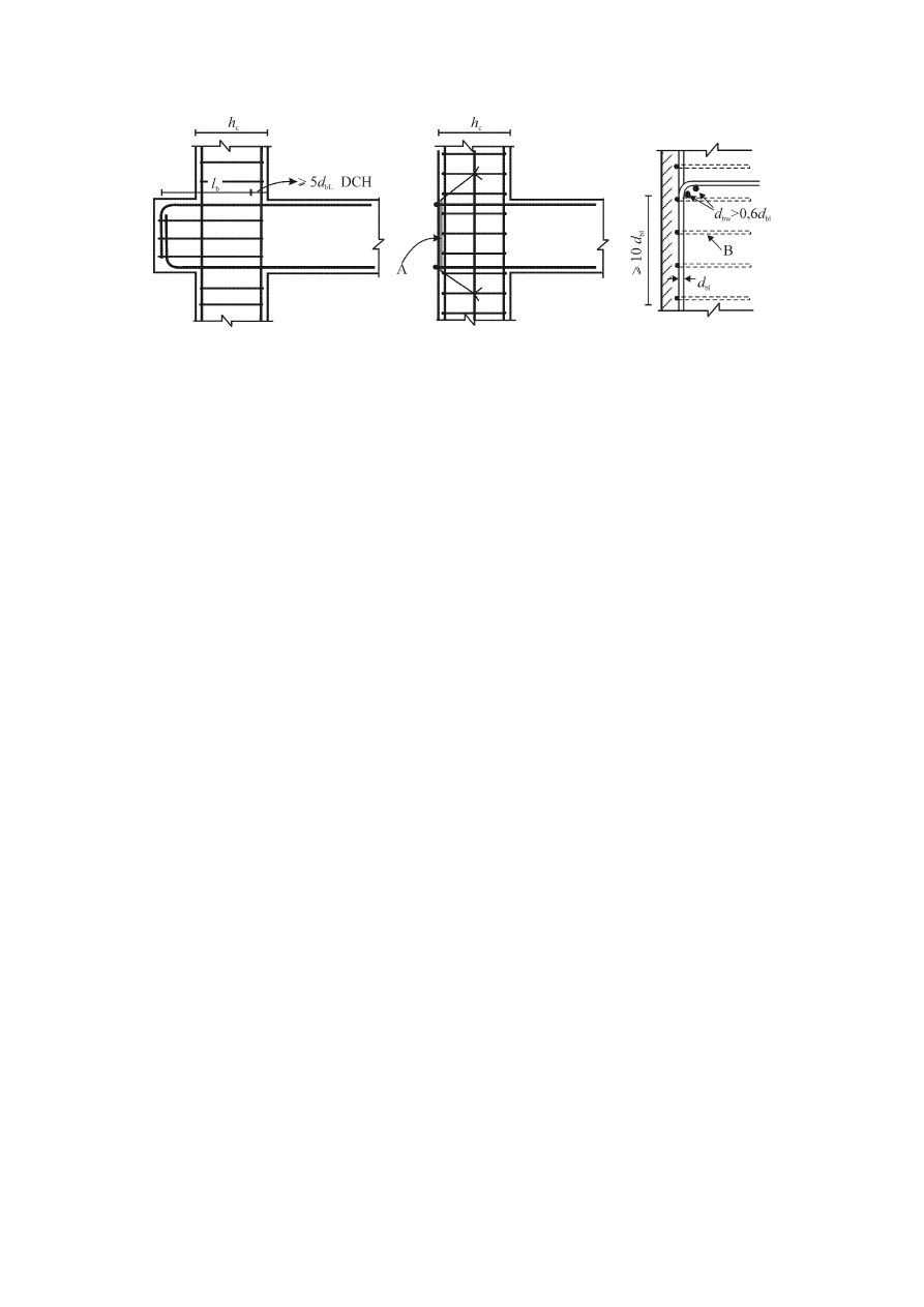
prEN 1998-1:2003 (E)
108
a)
b)
c)
Key
A
anchor plate;
B
hoops around column bars
Figure 5.13: Additional measures for anchorage in exterior beam-column joints
5.6.3 Splicing
of
bars
(1)P There shall be no lap-splicing by welding within the critical regions of structural
elements.
(2)P There may be splicing by mechanical couplers in columns and walls, if these
devices are covered by appropriate testing under conditions compatible with the
selected ductility class.
(3)P The transverse reinforcement to be provided within the lap length shall be
calculated in accordance with EN 1992-1-1:2004. In addition, the following
requirements shall also be met.
a) If the anchored and the continuing bar are arranged in a plane parallel to the
transverse reinforcement, the sum of the areas of all spliced bars,
ΣA
sL
, shall be used in
the calculation of the transverse reinforcement.
b) If the anchored and the continuing bar are arranged within a plane normal to the
transverse reinforcement, the area of transverse reinforcement shall be calculated on the
basis of the area of the larger lapped longitudinal bar, A
sL
;
c) The spacing, s, of the transverse reinforcement in the lap zone (in millimetres) shall
not exceed
{
}
100
/4;
min h
s
=
(5.51)
where h is the minimum cross-sectional dimension (in millimetres).
(4)
The required area of transverse reinforcement A
st
within the lap zone of the
longitudinal reinforcement of columns spliced at the same location (as defined in EN

prEN 1998-1:2003 (E)
109
1992-1-1:2004), or of the longitudinal reinforcement of boundary elements in walls,
may be calculated from the following expression:
(
)
(
)
ywd
yld
bl
st
50
/f
f
/
d
s
A
=
(5.52)
where
A
st
is the area of one leg of the transverse reinforcement;
d
bL
is the
diameter of the spliced bar;
s
is the spacing of the transverse reinforcement;
f
yld
is the design value of the yield strength of the longitudinal reinforcement;
f
ywd
is the design value of the yield strength of the transverse reinforcement.
5.7 Design and detailing of secondary seismic elements
(1)P Clause
5.7 applies to elements designated as secondary seismic elements, which
are subjected to significant deformations in the seismic design situation (e.g. slab ribs
are not subject to the requirements of 5.7). Such elements shall be designed and detailed
to maintain their capacity to support the gravity loads present in the seismic design
situation, when subjected to the maximum deformations under the seismic design
situation.
(2)P Maximum deformations due to the seismic design situation shall be calculated in
accordance with 4.3.4 and shall account for P-
∆ effects in accordance with 4.4.2.2(2)
and (3). They shall be calculated from an analysis of the structure in the seismic design
situation, in which the contribution of secondary seismic elements to lateral stiffness is
neglected and primary seismic elements are modelled with their cracked flexural and
shear stiffness.
(3)
Secondary seismic elements are deemed to satisfy the requirements of (1)P of
this subclause if bending moments and shear forces calculated for them on the basis of:
a) the deformations of (2)P of this subclause; and b) their cracked flexural and shear
stiffness, do not exceed their design flexural and shear resistance M
Rd
and V
Rd
,
respectively, as these are determined on the basis of EN 1992-1-1:2004.
5.8 Concrete foundation elements
5.8.1 Scope
(1)P The following paragraphs apply for the design of concrete foundation elements,
such as footings, tie-beams, foundation beams, foundation slabs, foundation walls, pile
caps and piles, as well as for connections between such elements, or between them and
vertical concrete elements. The design of these elements shall follow the rules of EN
1998-5:2004, 5.4.
(2)P If design action effects for the design of foundation elements of dissipative
structures are derived on the basis of capacity design considerations in accordance with
4.4.2.6(2)P, no energy dissipation is expected in these elements in the seismic design
situation. The design of these elements may follow the rules of 5.3.2(1)P.

prEN 1998-1:2003 (E)
110
(3)P If design action effects for foundation elements of dissipative structures are
derived on the basis of the analysis for the seismic design situation without the capacity
design considerations of 4.4.2.6(2)P, the design of these elements shall follow the
corresponding rules for elements of the superstructure for the selected ductility class.
For tie-beams and foundation beams the design shear forces need to be derived on the
basis of capacity design considerations, in accordance with 5.4.2.2 in DCM buildings,
or to 5.5.2.1(2)P, 5.5.2.1(3) in DCH buildings.
(4)
If design action effects for foundation elements have been derived using a value
of the behaviour factor q that is less than or equal to the upper limit of q for low
dissipative behaviour (1,5 in concrete buildings, or between 1,5 and 2,0 in steel or
composite steel-concrete buildings, in accordance with Note 1 of Table 6.1 or Note 1 of
Table 7.1, respectively), the design of these elements may follow the rules of 5.3.2(1)P
(see also 4.4.2.6(3)).
(5)
In box-type basements of dissipative structures, comprising: a) a concrete slab
acting as a rigid diaphragm at basement roof level; b) a foundation slab or a grillage of
tie-beams or foundation beams at foundation level, and c) peripheral and/or interior
foundation walls, designed in accordance with (2)P of this subclause, the columns and
beams (including those at the basement roof) are expected to remain elastic under the
seismic design situation and may be designed in accordance with 5.3.2(1)P. Shear walls
should be designed for plastic hinge development at the level of the basement roof slab.
To this end, in walls which continue with the same cross-section above the basement
roof, the critical region should be taken to extend below the basement roof level up to a
depth of h
cr
(see 5.4.3.4.2(1) and 5.5.3.4.5(1)). Moreover, the full free height of such
walls within the basement should be dimensioned in shear assuming that the wall
develops its flexural overstrength
γ
Rd
.M
Rd
(with
γ
Rd
=1,1 for DCM and
γ
Rd
=1,2 for DCH)
at the basement roof level and zero moment at the foundation level.
5.8.2 Tie-beams and foundation beams
(1)P Stub columns between the top of a footing or pile cap and the soffit of tie-beams
or foundation slabs shall be avoided. To this end, the soffit of tie-beams or foundation
slabs shall be below the top of the footing or the pile cap.
(2)
Axial forces in tie-beams or tie-zones of foundation slabs in accordance with
5.4.1.2(6) and (7) of EN 1998-5, should be taken in the verification to act together with
the action effects derived in accordance with 4.4.2.6(2)P or 4.4.2.6(3) for the seismic
design situation, taking into account second-order effects.
(3)
Tie-beams and foundation beams should have a cross-sectional width of at least
b
w,min
and a cross-sectional depth of at least h
w,min
.
NOTE The values ascribed to b
w,min
and h
w,min
for use in a country may be found in its National
Annex to this document. The recommended values are: b
w,min
= 0,25 m and h
w,min
= 0,4 m for
buildings with up to three storeys, or h
w,min
= 0,5 m for those with four storeys or more above the
basement.
(4)
Foundation slabs arranged in accordance with EN 1998-5:2004, 5.4.1.2(2) for
the horizontal connection of individual footings or pile caps, should have a thickness of
at least t
min
and a reinforcement ratio of at least
ρ
s,min
at the top and bottom.

prEN 1998-1:2003 (E)
111
NOTE The values ascribed to t
min
and
ρ
s,min
for use in a country may be found in its National
Annex to this document. The recommended values are: t
min
= 0,2 m and
ρ
s,min
= 0.2%.
(5)
Tie-beams and foundation beams should have along their full length a
longitudinal reinforcement ratio of at least
ρ
b,min
at both the top and the bottom.
NOTE The value ascribed to
ρ
b,min
for use in a country may be found in its National Annex to
this document. The recommended value of
ρ
b,min
is 0.4%.
5.8.3 Connections of vertical elements with foundation beams or walls
(1)P The common (joint) region of a foundation beam or foundation wall and a
vertical element shall follow the rules of 5.4.3.3 or 5.5.3.3 as a beam-column joint
region.
(2)
If a foundation beam or foundation wall of a DCH structure is designed for
action effects derived on the basis of capacity design considerations in accordance with
4.4.2.6(2)P, the horizontal shear force V
jhd
in the joint region is derived on the basis of
analysis results in accordance with 4.4.2.6(2)P, (4), (5), and (6).
(3)
If the foundation beam or foundation wall of a DCH structure is not designed in
accordance with the capacity design approach of 4.4.2.6(4), (5), (6) (see 5.8.1(3)P), the
horizontal shear force V
jhd
in the joint region is determined in accordance with
5.5.2.3(2), expressions (5.22), (5.23), for beam-column joints.
(4)
In DCM structures the connection of foundation beams or foundation walls with
vertical elements may follow the rules of 5.4.3.3.
(5)
Bents or hooks at the bottom of longitudinal bars of vertical elements should be
oriented so that they induce compression into the connection area.
5.8.4 Cast-in-place concrete piles and pile caps
(1)P The top of the pile up to a distance to the underside of the pile cap of twice the
pile cross-sectional dimension, d, as well as the regions up to a distance of 2d on each
side of an interface between two soil layers with markedly different shear stiffness (ratio
of shear moduli greater than 6), shall be detailed as potential plastic hinge regions. To
this end, they shall be provided with transverse and confinement reinforcement
following the rules for column critical regions of the corresponding ductility class or of
at least DCM.
(2)P When the requirement specified in 5.8.1(3)P is applied for the design of piles of
dissipative structures, piles shall be designed and detailed for potential plastic hinging at
the head. To this end, the length over which increased transverse and confinement
reinforcement is required at the top of the pile in accordance with (1)P of this subclause
is increased by 50%. Moreover, the ULS verification of the pile in shear shall use a
design shear force at least equal to that computed on the basis of 4.4.2.6(4) to (8).
(3)
Piles required to resist tensile forces or assumed as rotationally fixed at the top,
should be provided with anchorage in the pile cap to enable the development of the pile
design uplift resistance in the soil, or of the design tensile strength of the pile

prEN 1998-1:2003 (E)
112
reinforcement, whichever is lower. If the part of such piles embedded in the pile cap is
cast before the pile cap, dowels should be provided at the interface where the
connection occurs.
5.9 Local effects due to masonry or concrete infills
(1)
Because of the particular vulnerability of the infill walls of ground floors, a
seismically induced irregularity is to be expected there and appropriate measures should
be taken. If a more precise method is not used, the entire length of the columns of the
ground floor should be considered as the critical length and confined accordingly.
(2)
If the height of the infills is smaller than the clear length of the adjacent
columns, the following measures should be taken:
a) the entire length of the columns is considered as critical region and should be
reinforced with the amount and pattern of stirrups required for critical regions;
b) The consequences of the decrease of the shear span ratio of those columns should be
appropriately covered. To this end, 5.4.2.3 and 5.5.2.2 should be applied for the
calculation of the acting shear force, depending on the ductility class. In this calculation
the clear length of the column, l
cl,
should be taken equal to the length of the column not
in contact with the infills and themoment M
i,d
at the column section at the top of the
infill wall should be taken as being equal to
γ
Rd
.M
Rc,i
with
γ
Rd
=1,1 for DCM and 1,3 for
DCH and M
Rc,i
the design value of the moment of resistance of the column;
c) the transverse reinforcement to resist this shear force should be placed along the
length of the column not in contact with the infills and extend along a length h
c
(dimension of the column cross-section in the plane of the infill) into the column part in
contact with the infills;
d) if the length of the column not in contact with the infills is less than 1,5h
c
, the shear
force should be resisted by diagonal reinforcement.
(3)
Where the infills extend to the entire clear length of the adjacent columns, and
there are masonry walls on only one side of the column (e.g. corner columns), the
entire length of the column should be considered as a critical region and be reinforced
with the amount and pattern of stirrups required for critical regions.
(4) The
length,
l
c,
of columns over which the diagonal strut force of the infill is
applied, should be verified in shear for the smaller of the following two shear forces: a)
the horizontal component of the strut force of the infill, assumed to be equal to the
horizontal shear strength of the panel, as estimated on the basis of the shear strength of
bed joints; or b) the shear force computed in accordance with 5.4.2.3 or 5.5.2.2,
depending on the ductility class, assuming that the overstrength flexural capacity of the
column,
γ
Rd
.M
Rc,i
, develops at the two ends of the contact length, l
c
. The contact length
should be assumed to be equal to the full vertical width of the diagonal strut of the infill.
Unless a more accurate estimation of this width is made, taking into account the elastic
properties and the geometry of the infill and the column, the strut width may be
assumed to be a fixed fraction of the length of the panel diagonal.

prEN 1998-1:2003 (E)
113
5.10 Provisions for concrete diaphragms
(1)
A solid reinforced concrete slab may be considered to serve as a diaphragm, if it
has a thickness of not less than 70 mm and is reinforced in both horizontal directions
with at least the minimum reinforcement specified in EN 1992-1-1:2004.
(2)
A cast-in-place topping on a precast floor or roof system may be considered as a
diaphragm, if: a) it meets the requirements of (1) of this subclause; b) it is designed to
provide alone the required diaphragm stiffness and resistance; and c) it is cast over a
clean, rough substrate, or connected to it through shear connectors.
(3)P The seismic design shall include the ULS verification of reinforced concrete
diaphragms in DCH structures with the following properties:
− irregular geometries or divided shapes in plan, diaphragms with recesses and re-
entrances;
− irregular and large openings in the diaphragm;
− irregular distribution of masses and/or stiffnesses (as e.g. in the case of set-backs or
off-sets);
− basements with walls located only in part of the perimeter or only in part of the
ground floor area;
(4) Action-effects in reinforced concrete diaphragms may be estimated by
modelling the diaphragm as a deep beam or a plane truss or strut-and-tie model, on
elastic supports.
(5)
The design values of the action effects should be derived taking into account
4.4.2.5.
(6)
The design resistances should be derived in accordance with EN 1992-1-1:2004.
(7)
In cases of core or wall structural systems of DCH, it should be verified that the
transfer of the horizontal forces from the diaphragms to the cores or walls has occurred.
In this respect the following provisions apply:
a) the design shear stress at the interface of the diaphragm and a core or wall should be
limited to 1,5f
ctd
, to control cracking;
b) an adequate strength to guard against shear sliding failure should be ensured,
assuming that the strut inclination is 45
o
. Additional bars should be provided,
contributing to the shear strength of the interface between diaphragms and cores or
walls; anchorage of these bars should follow the provisions of 5.6.
5.11 Precast concrete structures
5.11.1 General
5.11.1.1 Scope and structural types
(1)P Clause
5.11 applies to the seismic design of concrete structures constructed
partly or entirely of precast elements.

prEN 1998-1:2003 (E)
114
(2)P Unless otherwise specified (see 5.11.1.3.2(4)), all provisions of Section 5 of this
Eurocode and of EN 1992-1-1:2004, Section 10, apply.
(3)
The following structural types, as defined in 5.1.2 and 5.2.2.1, are covered by
5.11:
− frame systems;
− wall systems;
− dual systems (mixed precast frames and precast or monolithic walls).
(4)
In addition the following systems are also covered:
− wall panel structures (cross wall structures);
− cell structures (precast monolithic room cell systems).
5.11.1.2 Evaluation of precast structures
(1)
In modelling of precast structures, the following evaluations should be made.
a) Identification of the different roles of the structural elements as one of the following:
− those resisting only gravity loads, e.g. hinged columns around a reinforced concrete
core;
− those resisting both gravity and seismic loads, e.g. frames or walls;
− those providing adequate connection between structural elements, e.g. floor or roof
diaphragms.
b) Ability to fulfil the seismic resistance provisions of 5.1 to 5.10 as follows:
− precast system able to satisfy all those provisions;
− precast systems which are combined with cast-in-situ columns or walls in order to
satisfy all those provisions;
− precast systems which deviate from those provisions and, by way of consequence,
need additional design criteria and should be assigned lower behaviour factors.
c) Identification of non-structural elements, which may be:
− completely uncoupled from the structure; or
− partially resisting the deformation of structural elements.
d) Identification of the effect of the connections on the energy dissipation capacity of
the structure:
− connections located well outside critical regions (as defined in 5.1.2(1)), not
affecting the energy dissipation capacity of the structure (see 5.11.2.1.1 and e.g.
Figure 5.14.a);
− connections located within critical regions but adequately over-designed with
respect to the rest of the structure, so that in the seismic design situation they remain
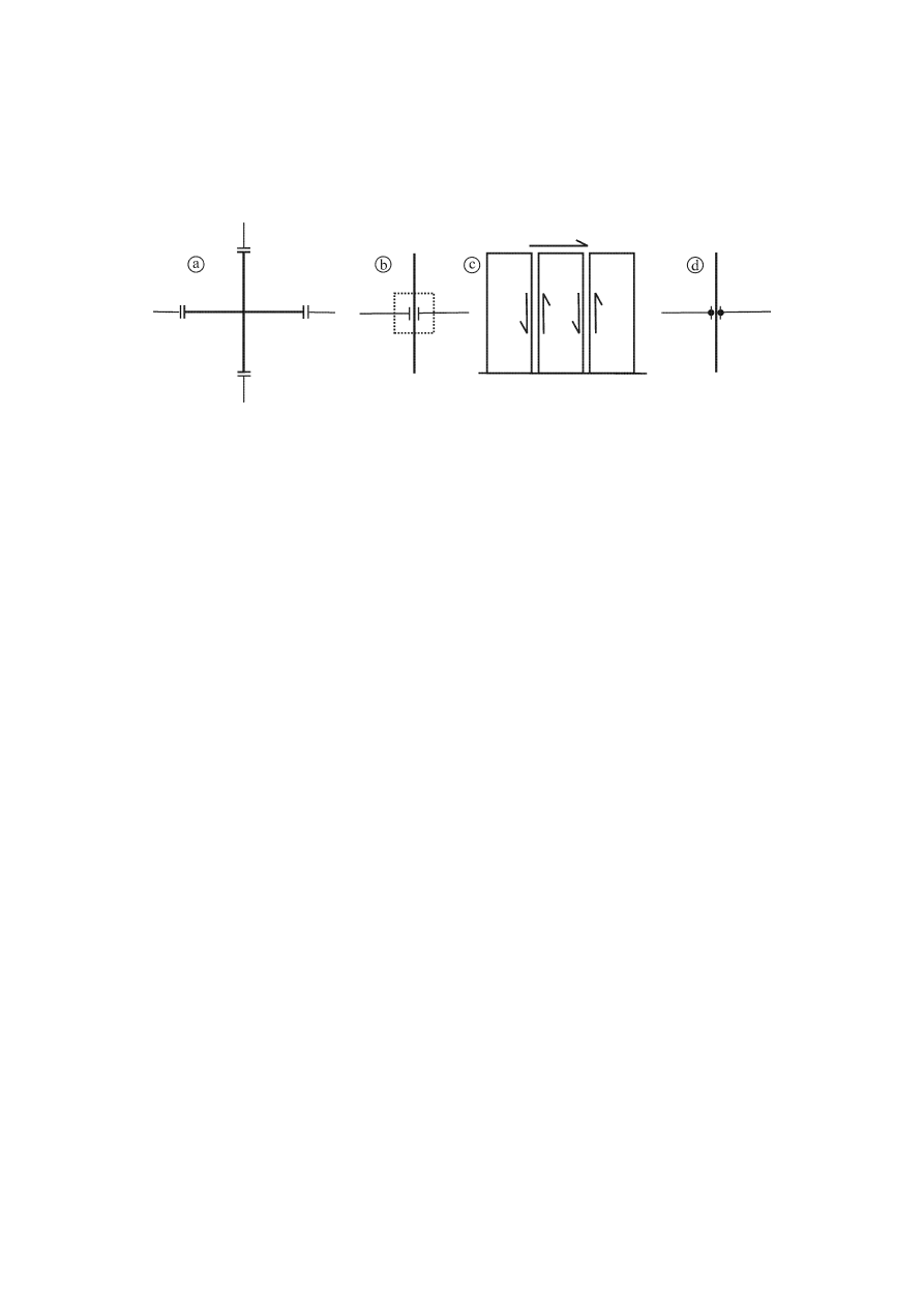
prEN 1998-1:2003 (E)
115
elastic while inelastic response occurs in other critical regions (see 5.11.2.1.2 and
e.g. Figure 5.14b);
− connections located within critical regions with substantial ductility (see 5.11.2.1.3
and e.g. Figure 5.14.c).
Figure 5.14: a) connection located outside critical regions; b) overdesigned
connection with plastic hinges shifted outside the connection; c) ductile shear
connections of large panels located within critical regions (e.g. at ground floor);
and d) ductile continuity connections located within critical regions of frames
5.11.1.3 Design criteria
5.11.1.3.1 Local resistance
(1) In precast elements and their connections, the possibility of response
degradation due to cyclic post-yield deformations should be taken into account.
Normally such response degradation is covered by the material partial factors on steel
and concrete (see 5.2.4(1)P and 5.2.4(2)). If it is not, the design resistance of precast
connections under monotonic loading should be appropriately reduced for the
verifications in the seismic design situation.
5.11.1.3.2 Energy dissipation
(1)
In precast concrete structures the prevailing energy dissipation mechanism
should be through plastic rotations within critical regions.
(2)
Besides energy dissipation through plastic rotations in critical regions, precast
structures can also dissipate energy through plastic shear mechanisms along joints,
provided that both of the following conditions are satisfied:
a) the restoring force should not degrade substantially during the seismic action; and
b) the possible instabilities should be appropriately avoided.
(3)
The three ductility classes provided in Section 5 for cast-in-place structures
apply for precast systems as well. Only 5.2.1(2) and 5.3 apply from Section 5, for the
design of precast buildings of Ductility Class L.
NOTE The selection of the ductility class for use in the various types of precast concrete systems
in a country or the parts of the country may be found in its National Annex of this document.
Ductility class L is recommended only for the low-seismicity case. For wall panel systems the
recommended ductility class is M.

prEN 1998-1:2003 (E)
116
(4)
The capacity of energy dissipation in shear may be taken into account, especially
in precast wall systems, by taking into account the values of the local slip-ductility
factors,
µ
s
, in the choice of the overall behaviour factor q.
5.11.1.3.3 Specific additional measures
(1)
Only regular precast structures are covered by 5.11 (see 4.2.3). Nonetheless, the
verification of precast elements of irregular structures may be based on the provisions of
this subsection.
(2)
All vertical structural elements should be extended to the foundation level
without a break.
(3) Uncertainties
related
to resistances are as in 5.2.3.7(2)P.
(4) Uncertainties
related
to ductility are as in 5.2.3.7(3)P.
5.11.1.4 Behaviour factors
(1) For
precast-structures
observing the provisions of 5.11, the value of the
behaviour factor q
p
may be calculated from the following expression, unless special
studies allow for deviations:
q
p
= k
p
⋅ q (5.53)
where
q
is the behaviour factor in accordance with expression (5.1);
k
p
is the reduction factor depending on the energy dissipation capacity of the
precast structure (see (2) of this subclause).
NOTE The values ascribed to k
p
for use in a country may be found in its National Annex of this
document. The recommended values are:
,
k
s
connection
of
s
other type
with
structures
for
5
0
5.11.2.1.3
or
,
5.11.2.1.2
,
5.11.2.1.1
to
according
connection
with
structures
for
00
,
1
p
(2)
For precast structures not observing the design provisions in 5.11, the behaviour
factor q
p
should be assumed to be up to 1,5.
5.11.1.5 Analysis of transient situation
(1)
During the erection of the structure, during which temporary bracing should be
provided, seismic actions do not have to be taken into account as a design situation.
However, whenever the occurrence of an earthquake might produce collapse of parts of
the structure with serious risk to human life, temporary bracings should be explicitly
designed for an appropriately reduced seismic action.
(2)
If not otherwise specified by special studies, this action may be assumed to be
equal to a fraction A
p
of the design action as defined in Section 3.

prEN 1998-1:2003 (E)
117
NOTE The value ascribed to A
p
for use in a country may be found in its National Annex of this
document. The recommended value of A
p
is 30%.
5.11.2 Connections of precast elements
5.11.2.1 General provisions
5.11.2.1.1 Connections located away from critical regions
(1)
Connections of precast elements considered to be away from critical regions
should be located at a distance from the end face of the closest critical region, at least
equal to the largest of the cross-section dimensions of the element where this critical
region lies.
(2)
Connections of this type should be dimensioned for: a) a shear force determined
from the capacity design rule of 5.4.2.2 and 5.4.2.3 with a factor to account for
overstrength due to strain-hardening of steel,
γ
Rd
, equal to 1,1 for DCM or to 1,2 for
DCH; and b) a bending moment at least equal to the acting moment from the analysis
and to 50% of the moment of resistance, M
Rd
, at the end face of the nearest critical
region, multiplied by the factor
γ
Rd
.
5.11.2.1.2 Overdesigned connections
(1)
The design action-effects of overdesigned connections should be derived on the
basis of the capacity design rules of 5.4.2.2 and 5.4.2.3, on the basis of overstrength
flexural resistances at the end sections of critical regions equal to
γ
Rd
.M
Rd
, with the
factor
γ
Rd
taken as being equal to 1,20 for DCM and to 1,35 for DCH.
(2)
Terminating reinforcing bars of the overdesigned connection should be fully
anchored before the end section(s) of the critical region.
(3)
The reinforcement of the critical region should be fully anchored outside the
overdesigned connection.
5.11.2.1.3 Energy dissipating connections
(1)
Such connections should conform to the local ductility criteria in 5.2.3.4 and in
the relevant paragraphs of 5.4.3 and 5.5.3.
(2)
Alternatively it should be demonstrated by cyclic inelastic tests of an appropriate
number of specimens representative of the connection, that the connection possesses
stable cyclic deformation and energy dissipation capacity at least equal to that of a
monolithic connection which has the same resistance and conforms to the local
ductility provisions of 5.4.3 or 5.5.3.
(3)
Tests on representative specimens should be performed following an appropriate
cyclic history of displacements, including at least three full cycles at an amplitude
corresponding to q
p
in accordance with 5.2.3.4(3).

prEN 1998-1:2003 (E)
118
5.11.2.2 Evaluation of the resistance of connections
(1)
The design resistance of the connections between precast concrete elements should
be calculated in accordance with the provisions of EN 1992-1-1:2004, 6.2.5 and of EN
1992-1-1:2004, Section 10, using the material partial factors of 5.2.4(2) and (3). If those
provisions do not adequately cover the connection under consideration, its resistance should
be evaluated by means of appropriate experimental studies.
(2)
In evaluating the resistance of a connection against sliding shear, friction
resistance due to external compressive stresses (as opposed to the internal stresses due
to the clamping effect of bars crossing the connection) should be neglected.
(3)
Welding of steel bars in energy dissipating connections may be structurally
taken into account when all of the following conditions are met:
a) only weldable steels are used;
b) welding materials, techniques and personnel ensure a loss of local ductility less than
10% of the ductility factor achieved if the connection were implemented without
welding.
(4)
Steel elements (sections or bars) fastened on concrete members and intended to
contribute to the seismic resistance should be analytically and experimentally
demonstrated to resist a cyclic loading history of imposed deformation at the target
ductility level, as specified in 5.11.2.1.3(2).
5.11.3 Elements
5.11.3.1 Beams
(1)P The relevant provisions of EN 1992-1-1:2004, Section 10 and of 5.4.2.1, 5.4.3.1,
5.5.2.1, 5.5.3.1 of this Eurocode apply, in addition to the rules set forth in 5.11.
(2)P Simply supported precast beams shall be structurally connected to columns or
walls. The connection shall ensure the transmission of horizontal forces in the design
seismic situation without reliance on friction.
(3)
In addition to the relevant provisions of EN 1992-1-1:2004, Section 10, the
tolerance and spalling allowances of the bearings should also be sufficient for the
expected displacement of the supporting member (see 4.3.4).
5.11.3.2 Columns
(1)
The relevant provisions of 5.4.3.2 and 5.5.3.2 apply, in addition to the rules set
forth in 5.11.
(2)
Column-to-column connections within critical regions are allowed only in
DCM.
(3)
For precast frame systems with hinged column-to-beam connections, the
columns should be fixed at the base with full supports in pocket foundations designed in
accordance with 5.11.2.1.2.

prEN 1998-1:2003 (E)
119
5.11.3.3 Beam-column joints
(1)
Monolithic beam-column joints (see figure 5.14a) should follow the relevant
provisions of 5.4.3.3 and 5.5.3.3.
(2)
Connections of beam-ends to columns (see figure 5.14b) and c) should be
specifically checked for their resistance and ductility, as specified in 5.11.2.2.1.
5.11.3.4 Precast large-panel walls
(1)
EN 1992-1-1, Section 10 applies with the following modifications:
a) The total minimum vertical reinforcement ratio refers to the actual cross-sectional
area of concrete and should include the vertical bars of the web and the boundary
elements;
b) Mesh reinforcement in a single curtain is not allowed;
c) A minimum confinement should be provided to the concrete near the edge of all
precast panels, as specified in 5.4.3.4.2 or 5.5.3.4.5 for columns, over a square section
of side length b
w
, where b
w
denotes the thickness of the panel.
(2)
The part of the wall panel between a vertical joint and an opening arranged
closer than 2,5b
w
to the joint, should be dimensioned and detailed in accordance with
5.4.3.4.2 or 5.5.3.4.5, depending on the ductility class.
(3)
Force-response degradation of the resistance of the connections should be
avoided.
(4)
To this end, all vertical joints should be rough or provided with shear keys and
verified in shear.
(5)
Horizontal joints under compression over their entire length may be formed
without shear keys. If they are partly in compression and partly in tension, they should
be provided with shear keys along the full length.
(6) The following additional rules apply for the verification of horizontal
connections of walls consisting of precast large panels:
a) the total tensile force produced by axial (with respect to the wall) action-effects
should be taken by vertical reinforcement arranged along the tensile area of the panel
and fully anchored in the body of the upper and lower panels. The continuity of this
reinforcement should be secured by ductile welding within the horizontal joint or,
preferably, within special keys provided for this purpose (Figure 5.15).
b) in horizontal connections which are partly in compression and partly in tension
(under the seismic design situation) the shear resistance verification (see 5.11.2.2)
should be made only along the part under compression. In such a case, the value of the
axial force N
Ed
should be replaced by the value of the total compressive force F
c
acting
on the compression area.
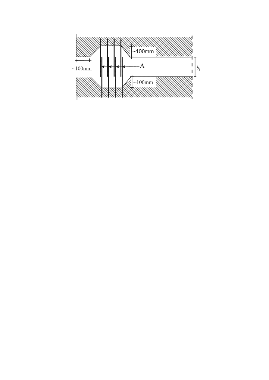
prEN 1998-1:2003 (E)
120
Key
A lap-welding
of
bars
Figure 5.15: Tensile reinforcement possibly needed at the edge of walls
(7)
The following additional design rules should be observed, to enhance local
ductility along the vertical connections of large panels:
a) minimum reinforcement should be provided across the connections equal to 0,10% in
connections which are fully compressed, and equal to 0,25% in connections which are
partly in compression and partly in tension;
b) the amount of reinforcement across the connections should be limited, to avoid
abrupt post-peak force response softening. In the absence of more specific evidence, the
reinforcement ratio should not exceed 2%;
c) such reinforcement should be distributed across the entire length of the connection. In
DCM this reinforcement may be concentrated in three bands (top, middle and bottom);
d) provision should be made to ensure continuity of reinforcement across panel-to-panel
connections. To this end, in vertical connections steel bars should be anchored either in
the form of loops or (in the case of joints with at least one face free) by welding across
the connection (see Figure 5.16);
e) to secure continuity along the connection after cracking, longitudinal reinforcement at
a minimum ratio of
ρ
c,min
should be provided within the grout filling the space of the
connection (see Figure 5.16).
NOTE The value ascribed to
ρ
c,min
for use in a country may be found in its National Annex to
this document. The recommended value is:
ρ
c,min
= 1%.
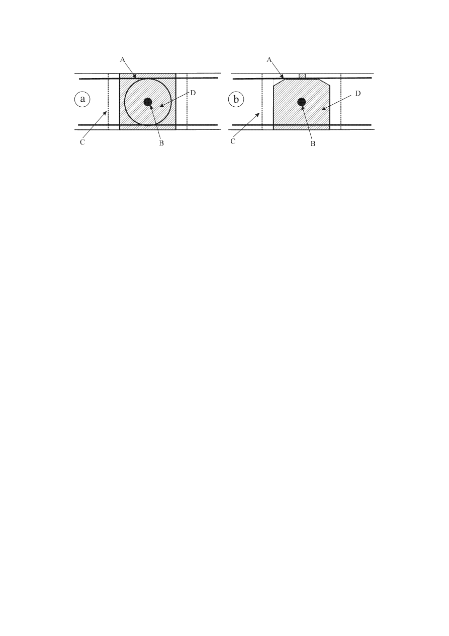
prEN 1998-1:2003 (E)
121
Key
A
reinforcement protruding across connection;
B
reinforcement along connection;
C shear
keys;
D
grout filling space between panels.
Figure 5.16: Cross-section of vertical connections between precast large-panels,
a) joint with two free faces; b) joint with one free face
(8)
As a result of the energy dissipation capacity along the vertical (and in part
along the horizontal) connections of large-panels, walls made of such precast panels are
exempt from the requirements in 5.4.3.4.2 and 5.5.3.4.5 regarding the confinement of
boundary elements.
5.11.3.5 Diaphragms
(1)
In addition to the provisions of EN 1992-1-1:2004, Section 10 relevant to slabs
and to the provisions of 5.10, the following design rules also apply in the case of floor
diaphragms made of precast elements.
(2)
When the rigid diaphragm condition in accordance with 4.3.1(4) is not satisfied,
the in-plane flexibility of the floor as well as of the connections to the vertical elements
should be taken into account in the model.
(3)
The rigid diaphragm behaviour is enhanced if the joints in the diaphragm are
located only over its supports. An appropriate topping of in-situ reinforced concrete can
drastically improve the rigidity of the diaphragm. The thickness of this topping layer
should be not less than 40 mm if the span between supports is less than 8 m, or not less
than 50 mm for longer spans; its mesh reinforcement should be connected to the vertical
resisting elements above and below.
(4)
Tensile forces should be resisted by steel ties accommodated at least along the
perimeter of the diaphragm, as well as along some joints of the precast slab elements. If
a cast in-situ topping is used, this additional reinforcement should be located in this
topping.
(5)
In all cases, these ties should form a continuous system of reinforcement along
and across the entire diaphragm and should be appropriately connected to each lateral
force resisting element.

prEN 1998-1:2003 (E)
122
(6)
In-plane acting shear forces along slab-to-slab or slab-to-beam connections
should be computed with an overdesign factor equal to 1,30. The design resistance
should be computed as in 5.11.2.2.
(7)
Primary seismic elements, both above and below the diaphragm, should be
adequately connected to the diaphragm. To this end, any horizontal joints should always
be properly reinforced. Friction forces due to external compressive forces should not be
relied upon.

prEN 1998-1:2003 (E)
123
6 SPECIFIC RULES FOR STEEL BUILDINGS
6.1 General
6.1.1 Scope
(1)P For the design of steel buildings, EN 1993 applies. The following rules are
additional to those given in EN 1993.
(2)P For buildings with composite steel-concrete structures, Section 7 applies.
6.1.2 Design
concepts
(1)P Earthquake
resistant
steel buildings shall be designed in accordance with one of
the following concepts (see Table 6.1):
− Concept a) Low-dissipative structural behaviour;
− Concept b) Dissipative structural behaviour.
Table 6.1: Design concepts, structural ductility classes and upper limit reference
values of the behaviour factors
Design concept
Structural ductility
class
Range of the
reference values of
the behaviour factor
q
Concept a)
Low dissipative structural
behaviour
DCL (Low)
≤ 1,5 - 2
DCM (Medium)
≤ 4
also limited by the
values of Table 6.2
Concept b)
Dissipative structural
behaviour
DCH (High)
only limited by the
values of Table 6.2
NOTE 1 The value ascribed to the upper limit of q for low dissipative behaviour, within the
range of Table 6.1, for use in a country may be found in its National Annex. The recommended
value of the upper limit of q for low-dissipative behaviour is 1,5.
NOTE 2 The National Annex of a particular country may give limitations on the choice of the
design concept and of the ductility class which are permissible within that country.
(2)P In concept a) the action effects may be calculated on the basis of an elastic
global analysis without taking into account a significant non-linear material behaviour.
When using the design spectrum defined in 3.2.2.5, the upper limit of the reference
value of the behaviour factor q may be taken between 1,5 and 2 (see Note 1 to (1) of this
subclause). In the case of irregularity in elevation the behaviour factor q should be
corrected as indicated in 4.2.3.1(7) but it need not be taken as being smaller than 1,5.

prEN 1998-1:2003 (E)
124
(3)
In concept a), if the upper limit of the reference value of q is taken as being
larger than 1,5, the primary seismic members of the structure should be of cross-
sectional classes 1, 2 or 3.
(4)
In concept a), the resistance of the members and of the connections should be
evaluated in accordance with EN 1993 without any additional requirements. For
buildings which are not seismically isolated (see Section 10), design in accordance with
concept a) is recommended only for low seismicity cases (see 3.2.1(4)).
(5)P In concept b) the capability of parts of the structure (dissipative zones) to resist
earthquake actions through inelastic behaviour is taken into account. When using the
design spectrum defined in 3.2.2.5, the reference value of behaviour factor q may be
taken as being greater than the upper limit value established in Table 6.1 and in Note 1
to (1) of this subclause for low dissipative structural behaviour. The upper limit value of
q depends on the Ductility Class and the structural type (see 6.3). When adopting this
concept b), the requirements given in 6.2 to 6.11 shall be fulfilled.
(6)P Structures designed in accordance with concept b) shall belong to structural
ductility classes DCM or DCH. These classes correspond to increased ability of the
structure to dissipate energy in plastic mechanisms. Depending on the ductility class,
specific requirements in one or more of the following aspects shall be met: class of steel
sections and rotational capacity of connections.
6.1.3 Safety
verifications
(1)P For ultimate limit state verifications the partial factor for steel
γ
s
=
γ
M
shall take
into account the possible strength degradation due to cyclic deformations.
NOTE 1 The National Annex may give a choice of
γ
s
.
NOTE 2 Assuming that, due to the local ductility provisions, the ratio between the residual
strength after degradation and the initial one is roughly equal to the ratio between the
γ
M
values
for accidental and for fundamental load combinations, it is recommended that the partial factor
γ
s
adopted for the persistent and transient design situations be applied.
(2)
In the capacity design checks specified in 6.5 to 6.8, the possibility that the
actual yield strength of steel is higher than the nominal yield strength should be taken
into account by a material overstrength factor
γ
ov
(see 6.2(3)).
6.2 Materials
(1)P Structural steel shall conform to standards referred to in EN 1993.
(2)P The distribution of material properties, such as yield strength and toughness, in
the structure shall be such that dissipative zones form where they are intended to in the
design.
NOTE Dissipative zones are expected to yield before other zones leave the elastic range during
the earthquake.

prEN 1998-1:2003 (E)
125
(3) The
requirement
(2)P may be satisfied if the yield strength of the steel of
dissipative zones and the design of the structure conform to one of the following
conditions a), b) or c):
a) the actual maximum yield strength f
y,max
of the steel of dissipative zones satisfies the
following expression f
y,max
≤ 1,1γ
ov
f
y
where
γ
ov
is the overstrength factor used in design; and
f
y
is the nominal yield strength specified for the steel grade.
NOTE 1 For steels of grade S235 and with
γ
ov
= 1,25 this method gives a maximum of f
y,max
=
323 N/mm
2
.
NOTE 2 The value ascribed to
γ
ov
for use in a Country to check condition a) may be found in its
National Annex. The recommended value is
γ
ov
= 1,25
b) the design of the structure is made on the basis of a single grade and nominal yield
strength f
y
for the steels both in dissipative and non dissipative zones; an upper value
f
y,max
is specified for the steel of dissipative zones; the nominal value f
y
of the steels
specified for non dissipative zones and connections exceeds the upper value of the yield
strength f
y,max
of dissipative zones.
NOTE This condition normally leads to the use of steels of grade S355 for non-dissipative
members and non dissipative connections (designed on the basis of the f
y
of S235 steels) and to
the use of steels of grade S235 for dissipative members or connections where the upper yield
strengths of steels of grade S235 is limited to f
y,max
= 355 N/mm
2
.
c)
the actual yield strength f
y,act
of the steel of each dissipative zone is determined from
measurements and the overstrength factor is computed for each dissipative zone as
γ
ov,act
= f
y,act
/ f
y
, f
y
being the nominal yield strength of the steel of dissipative zones.
NOTE This condition is applicable when known steels are taken from stock or to the assessment
of existing buildings or where safe side assumptions of yield strength made in design are
confirmed by measurements before fabrication.
(4)
If the conditions in (3)b of this subclause are satisfied, the overstrength factor,
γ
ov,
may be taken as being 1,00 in the design checks for structural elements defined in
6.5 to 6.8. In the verification of expression (6.1) for connections, the value to be used
for the overstrength factor
γ
ov
is the same as in (3)a).
(5)
If the conditions in (3)c) of this subclause are satisfied, the overstrength factor
γ
ov
should be taken as the maximum among the
γ
ov,act
values computed in the
verifications specified in 6.5 to 6.8.
(6)P For dissipative zones, the value of the yield strength f
y,max
taken into account in
observing the conditions in (3) of this subclause should be specified and noted on the
drawings.
(7)
The toughness of the steels and the welds should satisfy the requirements for the
seismic action at the quasi-permanent value of the service temperature (see EN 1993-1-
10:2004).

prEN 1998-1:2003 (E)
126
NOTE The National Annex may give information as to how EN 1993-1-10:2004 may be used in
the seismic design situation.
(8)
The required toughness of steel and welds and the lowest service temperature
adopted in combination with the seismic action should be defined in the project
specification.
(9)
In bolted connections of primary seismic members of a building, high strength
bolts of bolt grade 8.8 or 10.9 should be used.
(10)P The control of material properties shall be made in accordance with 6.11.
6.3 Structural types and behaviour factors
6.3.1 Structural
types
(1)P Steel buildings shall be assigned to one of the following structural types
according to the behaviour of their primary resisting structure under seismic actions (see
Figures 6.1 to 6.8).
a) Moment resisting frames, are those in which the horizontal forces are mainly resisted
by members acting in an essentially flexural manner.
b) Frames with concentric bracings, are those in which the horizontal forces are mainly
resisted by members subjected to axial forces.
c) Frames with eccentric bracings, are those in which the horizontal forces are mainly
resisted by axially loaded members, but where the eccentricity of the layout is such that
energy can be dissipated in seismic links by means of either cyclic bending or cyclic
shear.
d) Inverted pendulum structures, are defined in 5.1.2, and are structures in which
dissipative zones are located at the bases of columns.
e) Structures with concrete cores or concrete walls, are those in which horizontal forces
are mainly resisted by these cores or walls.
f) Moment resisting frames combined with concentric bracings.
g) Moment resisting frames combined with infills.
(2)
In moment resisting frames, the dissipative zones should be mainly located in
plastic hinges in the beams or the beam-column joints so that energy is dissipated by
means of cyclic bending. The dissipative zones may also be located in columns:
− at the base of the frame;
− at the top of the columns in the upper storey of multi-storey buildings;
− at the top and bottom of columns in single storey buildings in which N
Ed
in columns
conform to the inequality: N
Ed
/ N
pl,Rd
< 0,3.
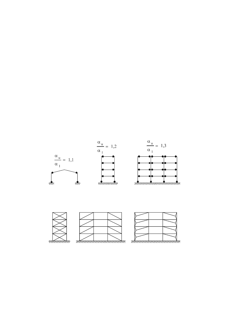
prEN 1998-1:2003 (E)
127
(3)
In frames with concentric bracings, the dissipative zones should be mainly
located in the tensile diagonals.
The bracings may belong to one of the following categories:
− active tension diagonal bracings, in which the horizontal forces can be resisted by
the tension diagonals only, neglecting the compression diagonals;
− V bracings, in which the horizontal forces can be resisted by taking into account
both tension and compression diagonals. The intersection point of these diagonals
lies on a horizontal member which shall be continuous.
K bracings, in which the intersection of the diagonals lies on a column (see Figure 6.9)
may not be used.
(4)
For frames with eccentric bracings configurations should be used that ensure
that all links will be active, as shown in Figure 6.4.
(5)
Inverted pendulum structures may be considered as moment resisting frames
provided that the earthquake resistant structures possess more than one column in each
resisting plane and that the following inequality of the limitation of axial force: N
Ed
< 0,3
N
pl, Rd
is satisfied in each column.
a)
b)
c)
Figure 6.1: Moment resisting frames (dissipative zones in beams and at bottom of
columns). Default values for
α
u
/
α
1
(see 6.3.2(3) and Table 6.2).
Figure 6.2: Frames with concentric diagonal bracings (dissipative zones in tension
diagonals only).
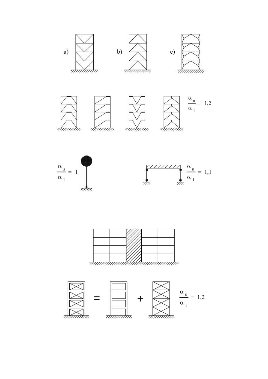
prEN 1998-1:2003 (E)
128
Figure 6.3: Frames with concentric V-bracings (dissipative zones in tension and
compression diagonals).
Figure 6.4: Frames with eccentric bracings (dissipative zones in bending or shear
links). Default values for
α
u
/
α
1
(see 6.3.2(3) and Table 6.2).
a)
b)
Figure 6.5: Inverted pendulum: a) dissipative zones at the column base; b)
dissipative zones in columns (N
Ed
/N
pl,Rd
< 0,3). Default values for
α
u
/
α
1
(see 6.3.2(3)
and Table 6.2).
Figure 6.6: Structures with concrete cores or concrete walls.
Figure 6.7: Moment resisting frame combined with concentric bracing (dissipative
zones in moment frame and in tension diagonals). Default value for
α
u
/
α
1
(see
6.3.2(3) and Table 6.2).
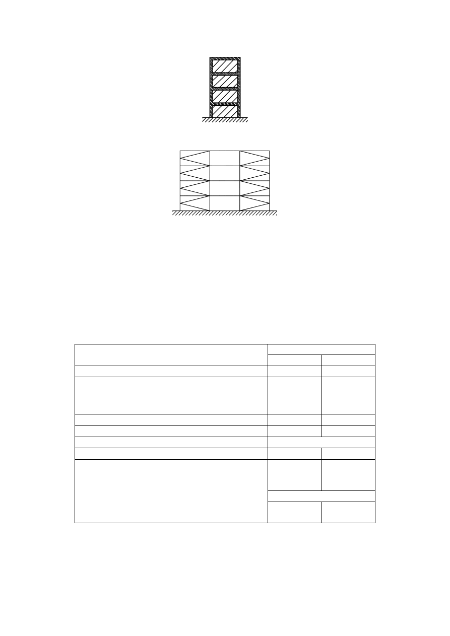
prEN 1998-1:2003 (E)
129
Figure 6.8: Moment resisting frame combined with infills.
Figure 6.9: Frame with K bracings (not allowed).
6.3.2 Behaviour
factors
(1)
The behaviour factor q, introduced in 3.2.2.5, accounts for the energy dissipation
capacity of the structure. For regular structural systems, the behaviour factor q should
be taken with upper limits to the reference values which are given in Table 6.2,
provided that the rules in 6.5 to 6.11 are met.
Table 6.2: Upper limit of reference values of behaviour factors for systems regular
in elevation
Ductility Class
STRUCTURAL TYPE
DCM DCH
a) Moment resisting frames
4
5
α
u
/
α
1
b) Frame with concentric bracings
Diagonal bracings
V-bracings
4
2
4
2,5
c) Frame with eccentric bracings
4
5
α
u
/
α
1
d) Inverted pendulum
2
2
α
u
/
α
1
e) Structures with concrete cores or concrete walls
See section 5
f) Moment resisting frame with concentric bracing
4
4
α
u
/
α
1
g) Moment resisting frames with infills
Unconnected concrete or masonry infills, in
contact with the frame
2 2
Connected reinforced concrete infills
See section 7
Infills isolated from moment frame (see
moment frames)
4
5
α
u
/
α
1
(2)
If the building is non-regular in elevation (see 4.2.3.3) the upper limit values of
q listed in Table 6.2 should be reduced by 20 % (see 4.2.3.1(7) and Table 4.1).

prEN 1998-1:2003 (E)
130
(3)
For buildings that are regular in plan, if calculations to evaluate
α
u
/
α
1
, are not
performed, the approximate default values of the ratio
α
u
/
α
1
presented in Figures 6.1 to
6.8 may be used. The parameters
α
1
and
α
u
are defined as follows:
α
1
is the value by which the horizontal seismic design action is multiplied in order
to first reach the plastic resistance in any member in the structure, while all other
design actions remain constant;
α
u
is the value by which the horizontal seismic design action is multiplied, in order
to form plastic hinges in a number of sections sufficient for the development of
overall structural instability, while all other design actions remain constant. The
factor
α
u
may be obtained from a nonlinear static (pushover) global analysis.
(4)
For buildings which are not regular in plan (see 4.2.3.2), the approximate value
of
α
u
/
α
1
that may be used when calculations are not performed for its evaluation are
equal to the average of (a) 1,0 and of (b) the value given in Figures 6.1 to 6.8.
(5) Values
of
α
u
/
α
1
higher than those specified in (3) and (4) of this subclause are
allowed, provided that they are confirmed by calculation of
α
u
/
α
1
with a nonlinear static
(pushover) global analysis.
(6)
The maximum value of
α
u
/
α
1
that may be used in a design is equal to 1,6, even
if the analysis mentioned in (5) of this subclause indicates higher potential values.
6.4 Structural
analysis
(1)
The design of floor diaphragms should conform to 4.4.2.5.
(2)
Except where otherwise stated in this section (e.g. frames with concentric
bracings, see 6.7.2(1) and (2)), the analysis of the structure may be made assuming that
all members of the seismic resisting structure are active.
6.5 Design criteria and detailing rules for dissipative structural behaviour
common to all structural types
6.5.1 General
(1)
The design criteria given in 6.5.2 should be applied to the earthquake-resistant
parts of structures designed in accordance with the concept of dissipative structural
behaviour.
(2)
The design criteria given in 6.5.2 are deemed to be satisfied if the detailing rules
given in 6.5.3 to 6.5.5 are followed.
6.5.2 Design criteria for dissipative structures
(1)P Structures with dissipative zones shall be designed such that yielding or local
buckling or other phenomena due to hysteretic behaviour do not affect the overall
stability of the structure.
NOTE The q factors given in Table 6.2 are deemed to conform to this requirement (see
2.2.2(2)).

prEN 1998-1:2003 (E)
131
(2)P Dissipative zones shall have adequate ductility and resistance. The resistance
shall be verified in accordance with EN 1993.
(3)
Dissipative zones may be located in the structural members or in the
connections.
(4)P If dissipative zones are located in the structural members, the non-dissipative
parts and the connections of the dissipative parts to the rest of the structure shall have
sufficient overstrength to allow the development of cyclic yielding in the dissipative
parts.
(5)P When dissipative zones are located in the connections, the connected members
shall have sufficient overstrength to allow the development of cyclic yielding in the
connections.
6.5.3 Design rules for dissipative elements in compression or bending
(1)P Sufficient local ductility of members which dissipate energy in compression or
bending shall be ensured by restricting the width-thickness ratio b/t according to the
cross-sectional classes specified in EN 1993-1-1:2004, 5.5.
(2)
Depending on the ductility class and the behaviour factor q used in the design,
the requirements regarding the cross-sectional classes of the steel elements which
dissipate energy are indicated in Table 6.3
Table 6.3: Requirements on cross-sectional class of dissipative elements depending
on Ductility Class and reference behaviour factor
Ductility class
Reference value of
behaviour factor q
Required cross-
sectional class
1,5 < q
≤ 2
class 1, 2 or 3
DCM
2 < q
≤ 4
class 1 or 2
DCH
q > 4
class 1
6.5.4 Design rules for parts or elements in tension
(1)
For tension members or parts of members in tension, the ductility requirement of
EN 1993-1-1:2004, 6.2.3(3) should be met.
6.5.5 Design rules for connections in dissipative zones
(1)P The design of connections shall be such as to limit localization of plastic strains,
high residual stresses and prevent fabrication defects.
(2)
Non dissipative connections of dissipative members made by means of full
penetration butt welds may be deemed to satisfy the overstrength criterion.

prEN 1998-1:2003 (E)
132
(3)
For fillet weld or bolted non dissipative connections, the following expression
should be satisfied:
R
d
≥ 1,1 γ
ov
R
fy
(6.1)
where
R
d
is the resistance of the connection in accordance with EN 1993;
R
fy
is the plastic resistance of the connected dissipative member based on the design
yield stress of the material as defined in EN 1993.
γ
ov
is the overstrength factor (see 6.1.3(2) and 6.2).
(4) Categories
B and C of bolted joints in shear in accordance with EN 1993-1-
8:2004, 3.4.1 and category E of bolted joints in tension in accordance with EN 1993-1-
8:2004, 3.4.2 should be used. Shear joints with fitted bolts are also allowed. Friction
surfaces should belong to class A or B as defined in ENV 1090-1.
(5)
For bolted shear connections, the design shear resistance of the bolts should be
higher than 1,2 times the design bearing resistance.
(6)
The adequacy of design should be supported by experimental evidence whereby
strength and ductility of members and their connections under cyclic loading should be
supported by experimental evidence, in order to conform to the specific requirements
defined in 6.6 to 6.9 for each structural type and structural ductility class. This applies
to partial and full strength connections in or adjacent to dissipative zones.
(7)
Experimental evidence may be based on existing data. Otherwise, tests should
be performed.
NOTE The National Annex may provide reference to complementary rules on acceptable
connection design.
6.6 Design and detailing rules for moment resisting frames
6.6.1 Design
criteria
(1)P Moment resisting frames shall be designed so that plastic hinges form in the
beams or in the connections of the beams to the columns, but not in the columns, in
accordance with 4.4.2.3. This requirement is waived at the base of the frame, at the top
level of multi-storey buildings and for single storey buildings.
(2)P Depending on the location of the dissipative zones, either 6.5.2(4)P or 6.5.2(5)P
applies.
(3)
The required hinge formation pattern should be achieved by conforming to
4.4.2.3, 6.6.2, 6.6.3 and 6.6.4.
6.6.2 Beams
(1)
Beams should be verified as having sufficient resistance against lateral and
lateral torsional buckling in accordance with EN 1993, assuming the formation of a

prEN 1998-1:2003 (E)
133
plastic hinge at one end of the beam. The beam end that should be considered is the
most stressed end in the seismic design situation.
(2)
For plastic hinges in the beams it should be verified that the full plastic moment
of resistance and rotation capacity are not decreased by compression and shear forces.
To this end, for sections belonging to cross-sectional classes 1 and 2, the following
inequalities should be verified at the location where the formation of hinges is expected:
0
,
1
Rd
pl,
Ed
≤
M
M
(6.2)
15
,
0
Rd
pl,
Ed
≤
N
N
(6.3)
5
,
0
Rd
pl,
Ed
≤
V
V
(6.4)
where
M
Ed,
G
Ed,
Ed
V
V
V
+
=
; (6.5)
N
Ed
is the design axial force;
M
Ed
is the design bending moment;
V
Ed
is the design shear;
N
pl, Rd
, M
pl
,
Rd
, V
pl, Rd
are design resistances in accordance with EN 1993;
V
Ed,G
is the design value of the shear force due to the non seismic actions;
V
Ed,M
is the
design value of the shear force due to the application of the plastic
moments M
pl,Rd,A
and M
pl,Rd,B
with opposite signs at the end sections A and B of
the beam.
NOTE V
Ed,M
= (M
pl,Rd,A
+M
pl,Rd,B
)/L is the most unfavourable condition, corresponding to a beam
with span L and dissipative zones at both ends.
(3)
For sections belonging to cross-sectional class 3, expressions (6.2) to (6.5)
should be checked replacing N
pl, Rd
, M
pl
,
Rd
, V
pl, Rd
with N
el, Rd
, M
el
,
Rd
, V
el, Rd
.
(4)
If the condition in expression (6.3) is not verified, the requirement specified in
(2) of this subclause is deemed to be satisfied if the provisions of EN 1993-1-1:2004,
6.2.9.1 are satisfied.
6.6.3 Columns
(1)P The columns shall be verified in compression considering the most unfavourable
combination of the axial force and bending moments. In the checks, N
Ed
, M
Ed
, V
Ed
should be computed as:

prEN 1998-1:2003 (E)
134
E
Ed,
ov
G
Ed,
Ed
E
Ed,
ov
G
Ed,
Ed
E
Ed,
ov
G
Ed,
Ed
1
,
1
1
,
1
1
,
1
V
V
V
M
M
M
N
N
N
Ω
γ
Ω
γ
Ω
γ
+
=
+
=
+
=
(6.6)
where
N
Ed,G
(M
Ed,G
, V
Ed,G
) are the compression force (respectively the bending moment and
shear force) in the column due to the non-seismic actions included in the
combination of actions for the seismic design situation;
N
Ed,E
(M
Ed,E
, V
Ed,E
)
are the compression force (respectively the bending moment and
shear force) in the column due to the design seismic action;
γ
ov
is the overstrength factor (see 6.1.3(2) and 6.2(3))
Ω
is the minimum value of
Ω
i
= M
pl,Rd,i
/M
Ed,i
of all beams in which dissipative
zones are located; M
Ed,i
is the design value of the bending moment in beam i in
the seismic design situation and M
pl,Rd,i
.is the corresponding plastic moment.
(2)
In columns where plastic hinges form as stated in 6.6.1(1)P, the verification
should take into account that in these plastic hinges the acting moment is equal to M
pl,Rd
.
(3)
The resistance verification of the columns should be made in accordance with
EN 1993-1-1:2004, Section 6.
(4)
The column shear force V
Ed
resulting from the structural analysis should satisfy
the following expression :
5
,
0
Rd
pl,
Ed
≤
V
V
(6.7)
(5)
The transfer of the forces from the beams to the columns should conform to the
design rules given in EN 1993-1-1:2004, Section 6.
(6)
The shear resistance of framed web panels of beam/column connections (see
Figure 6.10) should satisfy the following expression:
0
,
1
Rd
wp,
Ed
wp,
≤
V
V
(6.8)
where
V
wp,Ed
is the design shear force in the web panel due to the action effects, taking into
account the plastic resistance of the adjacent dissipative zones in beams or
connections;
V
wp,Rd
is the shear resistance of the web panel in accordance with EN 1993- 1-8:2004,
6.2.4.1. It is not required to take into account the effect of the stresses of the
axial force and bending moment on the plastic resistance in shear.

prEN 1998-1:2003 (E)
135
Figure 6.10: Web panel framed by flanges and stiffener
(7)
The shear buckling resistance of the web panels should also be checked to
ensure that it conforms to EN 1993-1-5:2004, Section 5:
V
wp,Ed
< V
wb,Rd
(6.9)
where
V
wb,Rd
is the shear buckling resistance of the web panel.
6.6.4 Beam to column connections
(1)
If the structure is designed to dissipate energy in the beams, the connections of
the beams to the columns should be designed for the required degree of overstrength
(see 6.5.5) taking into account the moment of resistance M
pl,Rd
and the shear force (V
Ed,G
+ V
Ed,M
) evaluated in 6.6.2.
(2) Dissipative semi-rigid and/or partial strength connections are permitted,
provided that all of the following requirements are verified:
a) the connections have a rotation capacity consistent with the global deformations;
b) members framing into the connections are demonstrated to be stable at the ultimate
limit state (ULS);
c) the effect of connection deformation on global drift is taken into account using non-
linear static (pushover) global analysis or non-linear time history analysis.
(3)
The connection design should be such that the rotation capacity of the plastic
hinge region
θ
p
is not less than 35 mrad for structures of ductility class DCH and 25
mrad for structures of ductility class DCM with q > 2. The rotation
θ
p
is defined as
θ
p
=
δ / 0,5L
(6.10)
where (see Figure 6.11):
δ
is the beam deflection at midspan ;
L
is the beam span
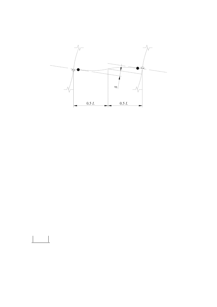
prEN 1998-1:2003 (E)
136
The rotation capacity of the plastic hinge region
θ
p
should be ensured under cyclic
loading without degradation of strength and stiffness greater than 20%. This
requirement is valid independently of the intended location of the dissipative zones.
Figure 6.11: Beam deflection for the calculation of
θ
p
.
(4)
In experiments made to assess
θ
p
the column web panel shear resistance should
conform to expression (6.8) and the column web panel shear deformation should not
contribute for more than 30% of the plastic rotation capability
θ
p
.
(5)
The column elastic deformation should not be included in the evaluation of
θ
p
.
(6)
When partial strength connections are used, the column capacity design should
be derived from the plastic capacity of the connections.
6.7 Design and detailing rules for frames with concentric bracings
6.7.1 Design
criteria
(1)P Concentric braced frames shall be designed so that yielding of the diagonals in
tension will take place before failure of the connections and before yielding or buckling
of the beams or columns.
(2)P The diagonal elements of bracings shall be placed in such a way that the
structure exhibits similar load deflection characteristics at each storey in opposite senses
of the same braced direction under load reversals.
(3)
To this end, the following rule should be met at every storey:
0,05
A
A
A
A
+
−
+
−
−
≤
+
(6.11)
where A
+
and A
-
are the areas of the horizontal projections of the cross-sections of the
tension diagonals, when the horizontal seismic actions have a positive or negative
direction respectively (see Figure 6.12).
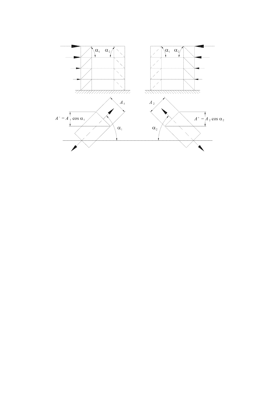
prEN 1998-1:2003 (E)
137
(+) direction
(-) direction
Figure 6.12: Example of application of 6.7.1(3)
6.7.2 Analysis
(1)P Under gravity load conditions, only beams and columns shall be considered to
resist such loads, without taking into account the bracing members.
(2)P The diagonals shall be taken into account as follows in an elastic analysis of the
structure for the seismic action:
− in frames with diagonal bracings, only the tension diagonals shall be taken into
account;
− in frames with V bracings, both the tension and compression diagonals shall be
taken into account.
(3)
Taking into account of both tension and compression diagonals in the analysis of
any type of concentric bracing is allowed provided that all of the following conditions
are satisfied:
a) a non-linear static (pushover) global analysis or non-linear time history analysis is
used;
b) both pre-buckling and post-buckling situations are taken into account in the
modelling of the behaviour of diagonals and;
c) background information justifying the model used to represent the behaviour of
diagonals is provided.

prEN 1998-1:2003 (E)
138
6.7.3 Diagonal
members
(1)
In frames with X diagonal bracings, the non-dimensional slenderness
λ as
defined in EN 1993-1-1:2004 should be limited to: 1,3 <
λ ≤ 2,0.
NOTE The 1,3 limit is defined to avoid overloading columns in the prebuckling stage (when
both compression and tension diagonals are active) beyond the action effects obtained from an
analysis at the ultimate stage where only the tension diagonal is taken as active.
(2)
In frames with diagonal bracings in which the diagonals are not positioned as X
diagonal bracings (see for instance Figure 6.12), the non-dimensional slenderness
λ
should be less than or equal to 2,0.
(3)
In frames with V bracings, the non-dimensional slenderness
λ should be less
than or equal to 2,0.
(4)
In structures up to two storeys, no limitation applies to
λ .
(5)
The yield resistance N
pl,Rd
of the gross cross-section of the diagonals should be
such that N
pl,Rd
≥ N
Ed
.
(6)
In frames with V bracings, the compression diagonals should be designed for the
compression resistance in accordance with EN 1993.
(7)
The connections of the diagonals to any member should satisfy the design rules
of 6.5.5.
(8)
In order to satisfy a homogeneous dissipative behaviour of the diagonals, it
should be checked that the maximum overstrength
Ω
i
defined in 6.7.4(1) does not differ
from the minimum value
Ω by more than 25%.
(9) Dissipative semi-rigid and/or partial strength connections are permitted,
provided that all of the following conditions are satisfied:
a) the connections have an elongation capacity consistent with global deformations;
b) the effect of connections deformation on global drift is taken into account using non-
linear static (pushover) global analysis or non-linear time history analysis.
6.7.4 Beams and columns
(1)
Beams and columns with axial forces should meet the following minimum
resistance requirement:
E
Ed,
ov
G
Ed,
Ed
Rd
pl,
.
1
,
1
)
(
N
N
M
N
Ω
γ
+
≥
(6.12)
where
N
pl,Rd
(M
Ed
) is the design buckling resistance of the beam or the column in
accordance with EN 1993, taking into account the interaction of the buckling

prEN 1998-1:2003 (E)
139
resistance with the bending moment M
Ed
, defined as its design value in the
seismic design situation;
N
Ed,G
is the axial force in the beam or in the column due to the non-seismic actions
included in the combination of actions for the seismic design situation;
N
Ed,E
is the axial force in the beam or in the column due to the design seismic action;
γ
ov
is the overstrength factor (see 6.1.3(2) and 6.2(3))
Ω
is the minimum value of
Ω
i
= N
pl,Rd,i
/N
Ed,i
over all the diagonals of the braced
frame system; where
N
pl,Rd,i
is the design resistance of diagonal i;
N
Ed,i
is the design value of the axial force in the same diagonal i in the seismic design
situation.
(2)
In frames with V bracings, the beams should be designed to resist:
− all non-seismic actions without considering the intermediate support given by the
diagonals;
− the unbalanced vertical seismic action effect applied to the beam by the braces after
buckling of the compression diagonal. This action effect is calculated using N
pl,Rd
for the brace in tension and
γ
pb
N
pl,Rd
for the brace in compression.
NOTE 1 The factor
γ
pb
is used for the estimation of the post buckling resistance of diagonals in
compression.
NOTE 2 The value ascribed to
γ
pb
for use in a country may be found in its National Annex to this
document. The recommended value is 0,3.
(3)P In frames with diagonal bracings in which the tension and compression
diagonals are not intersecting (e.g. diagonals of Figure 6.12), the design should take into
account the tensile and compression forces which develop in the columns adjacent to
the diagonals in compression and correspond to compression forces in these diagonals
equal to their design buckling resistance.
6.8 Design and detailing rules for frames with eccentric bracings
6.8.1 Design
criteria
(1)P Frames with eccentric bracings shall be designed so that specific elements or
parts of elements called seismic links are able to dissipate energy by the formation of
plastic bending and/or plastic shear mechanisms.
(2)P The structural system shall be designed so that a homogeneous dissipative
behaviour of the whole set of seismic links is realised.
NOTE The rules given hereafter are intended to ensure that yielding, including strain hardening
effects in the plastic hinges or shear panels, will take place in the links prior to any yielding or
failure elsewhere.
(3)
Seismic links may be horizontal or vertical components (see Figure 6.4).
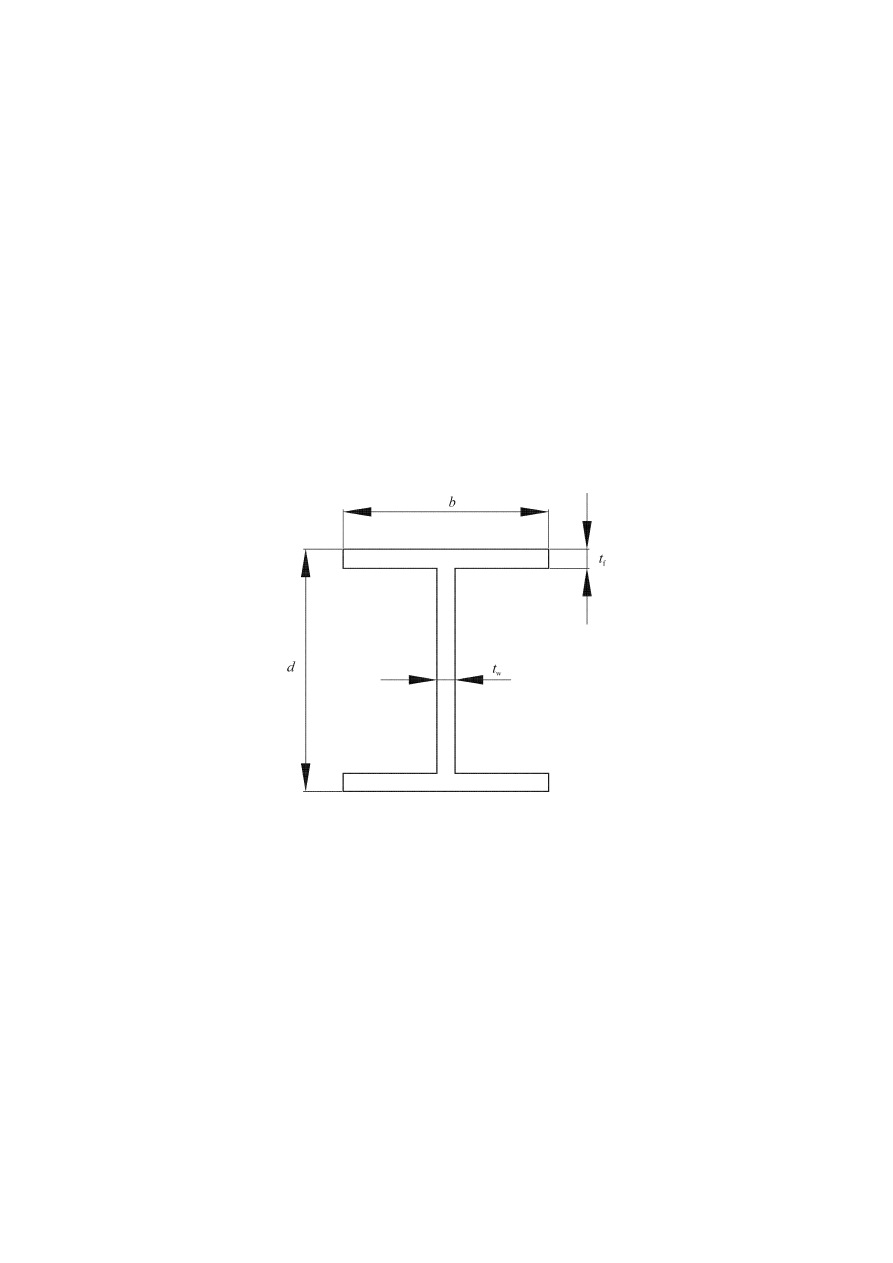
prEN 1998-1:2003 (E)
140
6.8.2 Seismic
links
(1)
The web of a link should be of single thickness without doubler plate
reinforcement and without a hole or penetration.
(2)
Seismic links are classified into 3 categories according to the type of plastic
mechanism developed:
− short links, which dissipate energy by yielding essentially in shear;
− long links, which dissipate energy by yielding essentially in bending;
− intermediate links, in which the plastic mechanism involves bending and shear.
(3)
For I sections, the following parameters are used to define the design resistances
and limits of categories:
M
p,link
= f
y
b t
f
(d-t
f
) (6.13)
V
p
,
link
= (f
y
/
√3) t
w
(d – t
f
) (6.14)
Figure 6.13: Definition of symbols for I link sections
(4) If
N
Ed
/N
pl,Rd
≤ 0,15, the design resistance of the link should satisfy both of the
following relationships at both ends of the link:
V
Ed
≤ V
p,link
(6.15)
M
Ed
≤ M
p,link
(6.16)
where
N
Ed
, M
Ed
, V
Ed
are the design action effects, respectively the design axial force, design
bending moment and design shear, at both ends of the link.
(5) If
N
Ed
/N
Rd
> 0,15, expressions (6.15), (6.16) should be satisfied with the
following reduced values V
p
,
link
,
r
and M
p
,
link
,
r
used instead of V
p
,
link
and M
p
,
link

prEN 1998-1:2003 (E)
141
(
)
[
]
5
,
0
2
Rd
pl,
Ed
link
,
p
r
,
link
,
p
/
1
N
N
V
V
−
=
(6.17)
(
)
−
=
Rd
pl,
Ed
link
,
p
r
,
link
,
p
/
1
N
N
M
M
(6.18)
(6) If
N
Ed
/N
Rd
≥ 0,15, the link length e should not exceed:
e
≤ 1,6 M
p,link
/V
p,link
when R < 0,3,
(6.19)
or
e
≤ (1,15 – 0,5 R) 1,6 M
p,link
/V
p,link
when R
≥ 0,3
(6.20)
where R = N
Ed
.t
w
.(d –2t
f
) / (V
Ed
.A), in which A is the gross area of the link.
(7)
To achieve a global dissipative behaviour of the structure, it should be checked
that the individual values of the ratios
Ω
i
defined in 6.8.3(1) do not exceed the minimum
value
Ω resulting from 6.8.3(1) by more than 25% of this minimum value.
(8)
In designs where equal moments would form simultaneously at both ends of the
link (see Figure 6.14.a), links may be classified according to the length e. For I sections,
the categories are:
− short links
e < e
s
= 1,6 M
p,link
/V
p,link
(6.21)
− long links
e > e
L
= 3,0 M
p,link
/V
p,link
(6.22)
− intermediate links
e
s
< e < e
L
(6.23)
(9)
In designs where only one plastic hinge would form at one end of the link (see
Figure 6.14.b), the value of the length e defines the categories of the links.For I sections
the categories are:
− short links
e < e
s
= 0,8 (1+
α) M
p,link
/V
p,link
(6.24)
− long links
e > e
L
= 1,5 (1+
α) M
p,link
/V
p,link
(6.25)
− intermediate links
e
s
< e < e
L
.
(6.26)
where
α is the ratio of the smaller bending moments M
Ed,A
at one end of the link in the
seismic design situation, to the greater bending moments M
Ed,B
at the end where the
plastic hinge would form, both moments being taken as absolute values.
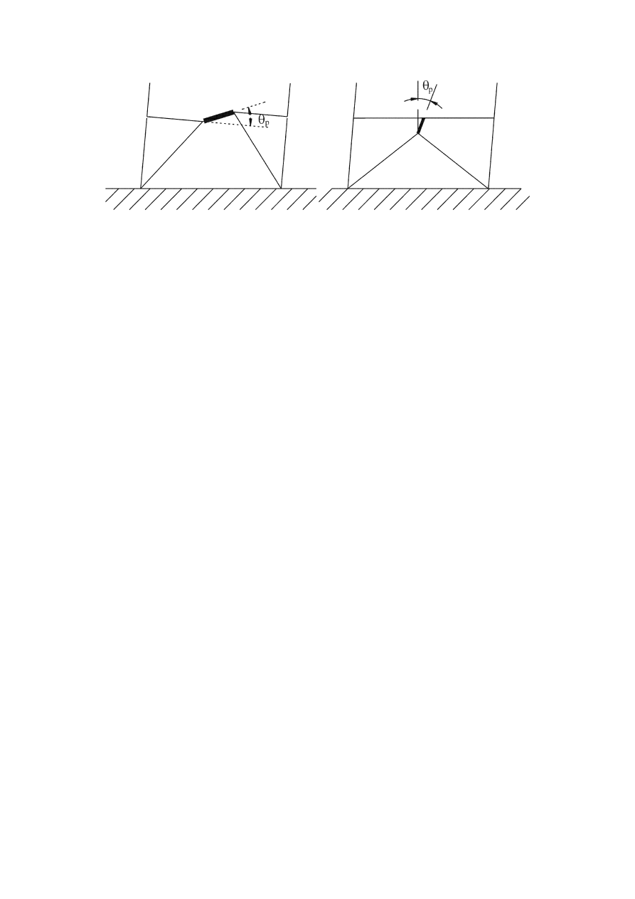
prEN 1998-1:2003 (E)
142
a)
b)
Figure 6.14: a) equal moments at link ends; b) unequal moments at link ends
(10) The link rotation angle
θ
p
between the link and the element outside of the link as
defined in 6.6.4(3) should be consistent with global deformations. It should not exceed
the following values:
−
short links
θ
p
≤ θ
pR
= 0,08 radians
(6.27)
−
long links
θ
p
≤ θ
pR
= 0,02 radians
(6.28)
−
intermediate links
θ
p
≤ θ
pR
= the value determined by linear interpolation
between
the
above
values.
(6.29)
(11) Full-depth
web
stiffeners should be provided on both sides of the link web at the
diagonal brace ends of the link. These stiffeners should have a combined width of not
less than (b
f
– 2t
w
) and a thickness not less than 0,75t
w
nor 10 mm, whichever is larger.
(12) Links should be provided with intermediate web stiffeners as follows:
a) short links should be provided with intermediate web stiffeners spaced at intervals
not exceeding (30t
w
– d/5) for a link rotation angle
θ
p
of 0,08 radians or (52t
w
– d/5) for
link rotation angles
θ
p
of 0,02 radians or less. Linear interpolation should be used for
values of
θ
p
between 0,08 and 0,02 radians;
b) long links should be provided with one intermediate web stiffener placed at a
distance of 1,5 times b from each end of the link where a plastic hinge would form;
c) intermediate links should be provided with intermediate web stiffeners meeting the
requirements of a) and b) above;
d) intermediate web stiffeners are not required in links of length e greater than 5 M
p
/V
p
;
e) intermediate web stiffeners should be full depth. For links that are less than 600 mm
in depth d, stiffeners are required on only one side of the link web. The thickness of
one-sided stiffeners should be not less than t
w
or 10 mm, whichever is larger, and the
width should be not less than (b/2) – t
w
. For links that are 600 mm in depth or greater,
similar intermediate stiffeners should be provided on both sides of the web.
(13) Fillet welds connecting a link stiffener to the link web should have a design
strength adequate to resist a force of
γ
ov
f
y
A
st
, where A
st
is the area of the stiffener. The

prEN 1998-1:2003 (E)
143
design strength of fillet welds fastening the stiffener to the flanges should be adequate
to resist a force of
γ
ov
A
st
f
y
/4.
(14) Lateral supports should be provided at both the top and bottom link flanges at
the ends of the link. End lateral supports of links should have a design axial resistance
sufficient to provide lateral support for forces of 6% of the expected nominal axial
strength of the link flange computed as f
y
b
t
f
.
(15) In beams where a seismic link is present, the shear buckling resistance of the
web panels outside of the link should be checked to conform to EN 1993-1-5:2004,
Section 5.
6.8.3 Members not containing seismic links
(1)
The members not containing seismic links, like the columns and diagonal
members, if horizontal links in beams are used, and also the beam members, if vertical
links are used, should be verified in compression considering the most unfavourable
combination of the axial force and bending moments:
E
Ed,
ov
G
Ed,
Ed
Ed
Rd
1
,
1
)
,
(
N
N
V
M
N
Ω
γ
+
≥
(6.30)
where
N
Rd
(M
Ed
,V
Ed
) is the axial design resistance of the column or diagonal member in
accordance with EN 1993, taking into account the interaction with the bending
moment M
Ed
and the shear V
Ed
taken at their design value in the seismic
situation;
N
Ed,G
is the compression force in the column or diagonal member due to the non-
seismic actions included in the combination of actions for the seismic design
situation;
N
Ed,E
is the
compression force in the column or diagonal member due to the design
seismic action;
γ
ov
is the overstrength factor (see 6.1.3(2) and 6.2(3))
Ω
is a multiplicative factor which is the minimum of the following values:
the minimum value of
Ω
i
= 1,5 V
p,link,i
/V
Ed,i
among all short links;
the minimum value of
Ω
i
= 1,5 M
p,link,i
/M
Ed,i
among all intermediate and long links;
where
V
Ed,i
, M
Ed,i
are the design values of the shear force and of the bending moment in
link i in the seismic design situation;
V
p,link,i
, M
p,link,i
are the shear
and bending plastic design resistances of link i as in
6.8.2(3).

prEN 1998-1:2003 (E)
144
6.8.4 Connections of the seismic links
(1)
If the structure is designed to dissipate energy in the seismic links, the
connections of the links or of the element containing the links should be designed for
action effects E
d
computed as follows:
E
d,
ov
G
d,
d
1
,
1
E
Ω
γ
E
E
l
+
≥
(6.31)
where
E
d,G
is the action effect in the connection due to the non-seismic actions included in
the combination of actions for the seismic design situation;
E
d,E
is the
action effect in the connection due to the design seismic action;
γ
ov
is the overstrength factor (see 6.1.3(2) and 6.2(3))
Ω
i
is the overstrength factor computed in accordance with 6.8.3(1) for the link.
(2)
In the case of semi-rigid and/or partial strength connections, the energy
dissipation may be assumed to originate from the connections only. This is allowable,
provided that all of the following conditions are satisfied:
a) the connections have rotation capacity sufficient for the corresponding deformation
demands;
b) members framing into the connections are demonstrated to be stable at the ULS;
c) the effect of connection deformations on global drift is taken into account.
(3)
When partial strength connections are used for the seismic links, the capacity
design of the other elements in the structure should be derived from the plastic capacity
of the links connections.
6.9 Design rules for inverted pendulum structures
(1)
In inverted pendulum structures (defined in 6.3.1(d)), the columns should be
verified in compression considering the most unfavourable combination of the axial
force and bending moments.
(2)
In the checks, N
Ed
, M
Ed
, V
Ed
should be computed as in 6.6.3.
(3)
The non-dimensional slenderness of the columns should be limited to
λ ≤ 1,5.
(4)
The interstorey drift sensitivity coefficient
θ as defined in 4.4.2.2 should be
limited to
θ ≤ 0,20.

prEN 1998-1:2003 (E)
145
6.10 Design rules for steel structures with concrete cores or concrete walls and for
moment resisting frames combined with concentric bracings or infills
6.10.1 Structures with concrete cores or concrete walls
(1)P The steel elements shall be verified in accordance with this Section and EN
1993, while the concrete elements shall be designed in accordance with Section 5.
(2)P The elements in which an interaction between steel and concrete exists shall be
verified in accordance with Section 7.
6.10.2 Moment resisting frames combined with concentric bracings
(1)
Dual structures with both moment resisting frames and braced frames acting in
the same direction should be designed using a single q factor. The horizontal forces
should be distributed between the different frames according to their elastic stiffness.
(2)
The moment resisting frames and the braced frames should conform to 6.6, 6.7
and 6.8.
6.10.3 Moment resisting frames combined with infills
(1)P Moment resisting frames in which reinforced concrete infills are positively
connected to the steel structure shall be designed in accordance with Section 7.
(2)P The moment resisting frames in which the infills are structurally disconnected
from the steel frame on the lateral and top sides shall be designed as steel structures.
(3)
The moment resisting frames in which the infills are in contact with the steel
frame, but are not positively connected to that frame, should satisfy the following rules:
a) the infills should be uniformly distributed in elevation in order not to increase locally
the ductility demand on the frame elements. If this is not verified, the building should be
considered as non-regular in elevation;
b) the frame-infill interaction should be taken into account. The internal forces in the
beams and columns due to the diagonal strut action in the infills should be taken into
account. The rules in 5.9 may be used to this end;
c) the steel frames should be verified in accordance with the rules in this clause, while
the reinforced concrete or masonry infills should be designed in accordance with EN
1992-1-1:2004 and in accordance with Sections 5 or 9.
6.11 Control of design and construction
(1)P The control of design and construction shall ensure that the real structure
corresponds to the designed structure.
(2)
To this end, in addition to the provisions of EN 1993, the following
requirements should be met:

prEN 1998-1:2003 (E)
146
a) the drawings made for fabrication and erection should indicate the details of
connections, sizes and qualities of bolts and welds as well as the steel grades of the
members, noting the maximum permissible yield stress f
y,max
of the steel to be used by
the fabricator in the dissipative zones;
b) the compliance of the materials with 6.2 should be checked;
c) the control of the tightening of the bolts and of the quality of the welds should follow
the rules in EN 1090;
d) during construction it should be ensured that the yield stress of the actual steel used
does not exceed f
ymax
noted on the drawings for dissipative zones by more than 10%.
(2)P Whenever one of the above conditions is not satisfied, corrections or
justifications shall be provided in order to meet the requirements of EN 1998-1 and
assure the safety of the structure.

prEN 1998-1:2003 (E)
147
7 SPECIFIC RULES FOR COMPOSITE STEEL – CONCRETE BUILDINGS
7.1 General
7.1.1 Scope
(1)P For the design of composite steel - concrete buildings, EN 1994-1-1:2004
applies. The following rules are additional to those given in EN 1994-1-1:2004.
(2)
Except where modified by the provisions of this Section, the provisions of
Sections 5 and 6 apply.
7.1.2 Design
concepts
(1)P Earthquake
resistant
composite buildings shall be designed in accordance with
one of the following design concepts (see Table 7.1):
− Concept a) Low-dissipative structural behaviour.
− Concept b) Dissipative structural behaviour with composite dissipative zones;
− Concept c) Dissipative structural behaviour with steel dissipative zones.
Table 7.1: Design concepts, structural ductility classes and upper limit of reference
values of the behaviour factors
Design concept
Structural ductility class
Range of the reference
values of the behaviour
factor q
Concept a)
Low-dissipative structural
behaviour
DCL (Low)
≤ 1,5 - 2
DCM (Medium)
≤ 4
also limited by the
values of Table 7.2
Concepts b) or c)
Dissipative structural
behaviour
DCH (High)
only limited by the
values of Table 7.2
NOTE 1 The value ascribed to the upper limit of q for low dissipative behaviour, within the
range of Table 7.1, for use in a country may be found in its National Annex to this document.
The recommended value of the upper limit of q for low-dissipative behaviour is 1,5.
NOTE 2 The National Annex of a particular country may give limitations on the choice of the
design concept and of the ductility class which are permissible within that country.
(2)P In concept a), the action effects may be calculated on the basis of an elastic
analysis without taking into account non-linear material behaviour but considering the
reduction in the moment of inertia due to the cracking of concrete in part of the beam
spans, in accordance with the general structural analysis rules defined in 7.4 and to the
specific rules defined in 7.7 to 7.11 related to each structural type. When using the
design spectrum defined in 3.2.2.5, the upper limit to the reference value of the
behaviour factor q is taken between 1,5 and 2 (see Note 1 to (1) of this subclause). In

prEN 1998-1:2003 (E)
148
case of irregularity in elevation the upper limit value of the behaviour factor q should be
corrected as indicated in 4.2.3.1(7) but it need not be taken as being smaller than 1,5.
(3)
In concept a) the resistance of the members and of the connections should be
evaluated in accordance with EN 1993 and EN 1994 without any additional
requirements. For buildings which are not base-isolated (see Section 10), design to
concept a) is recommended only for low seismicity cases (see 3.2.1(4)).
(4)
In concepts b) and c), the capability of parts of the structure (dissipative zones)
to resist earthquake actions through inelastic behaviour is taken into account. When
using the design response spectrum defined in 3.2.2.5, the upper limit to the reference
value of the behaviour factor q is taken as being greater than the upper value established
in Table 7.1 and in Note 1 to (1) of this subclause for low dissipative structural
behaviour. The upper limit value of q depends on the ductility class and the structural
type (see 7.3). When adopting concepts b) or c) the requirements given in 7.2 to 7.12
should be fulfilled.
(5)P In concept c), structures are not meant to take advantage of composite behaviour
in dissipative zones; the application of concept c) is conditioned by a strict compliance
to measures that prevent involvement of the concrete in the resistance of dissipative
zones. In concept c) the composite structure is designed in accordance with EN 1994-1-
1:2004 under non seismic loads and in accordance with Section 6 to resist earthquake
action. The measures preventing involvement of the concrete are given in 7.7.5.
(6)P The design rules for dissipative composite structures (concept b), aim at the
development of reliable local plastic mechanisms (dissipative zones) in the structure and
of a reliable global plastic mechanism dissipating as much energy as possible under the
design earthquake action. For each structural element or each structural type considered
in this Section, rules allowing this general design objective to be achieved are given in
7.5 to 7.11 with reference to what are called the specific criteria. These criteria aim at
the development of a global mechanical behaviour for which design provisions can be
given.
(7)P Structures designed in accordance with concept b) shall belong to structural
ductility classes DCM or DCH. These classes correspond to increased ability of the
structure to dissipate energy in plastic mechanisms. A structure belonging to a given
ductility class shall meet specific requirements in one or more of the following aspects:
class of steel sections, rotational capacity of connections and detailing.
7.1.3 Safety
verifications
(1)P 5.2.4(1)P and 6.1.3(1)P and its Notes apply.
(2)
5.2.4(2) applies.
(3)
5.2.4(3) applies.
(4)
In the capacity design checks relevant for structural steel parts, 6.2(3) and its
Notes apply.

prEN 1998-1:2003 (E)
149
7.2 Materials
7.2.1 Concrete
(1)
In dissipative zones, the prescribed concrete class should not be lower than
C20/25. If the concrete class is higher than C40/50, the design is not within the scope of
EN 1998-1.
7.2.2 Reinforcing
steel
(1)P For ductility class DCM the reinforcing steel taken into account in the plastic
resistance of dissipative zones shall be of class B or C in accordance with EN 1992-1-
1:2004 Table C.1. For ductility class DCH the reinforcing steel taken into account in the
plastic resistance of dissipative zones shalld be of class C according to the same Table.
(2)P Steel of class B or C ( EN 1992-1-1:2004, Table C.1) shall be used in highly
stressed regions of non dissipative structures. This requirement applies to both bars and
welded meshes.
(3)P Except for closed stirrups or cross ties, only ribbed bars are allowed as
reinforcing steel in regions with high stresses.
(4)
Welded meshes not conforming to the ductility requirements of (1)P of this
subclause should not be used in dissipative zones. If such meshes are used, ductile
reinforcement duplicating the mesh should be placed and their resistance capacity
accounted for in the capacity analysis.
7.2.3 Structural steel
(1)P The requirements are those specified in 6.2.
7.3 Structural types and behaviour factors
7.3.1 Structural
types
(1)P Composite steel-concrete structures shall be assigned to one of the following
structural types according to the behaviour of their primary resisting structure under
seismic actions:
a) Composite moment resisting frames are those with the same definition and
limitations as in 6.3.1(1)a, but in which beams and columns may be either structural
steel or composite steel-concrete (see Figure 6.1);
b) Composite concentrically braced frames are those with the same definition and
limitations as in 6.3.1(1)b and Figures 6.2 and 6.3. Columns and beams may be either
structural steel or composite steel-concrete. Braces shall be structural steel;
c) Composite eccentrically braced frames are those with the same definition and
configurations as in 6.3.1(1)c and Figure 6.4. The members which do not contain the
links may be either structural steel or composite steel-concrete. Other than for the slab,
the links shall be structural steel. Energy dissipation shall occur only through yielding in
bending or shear of these links;
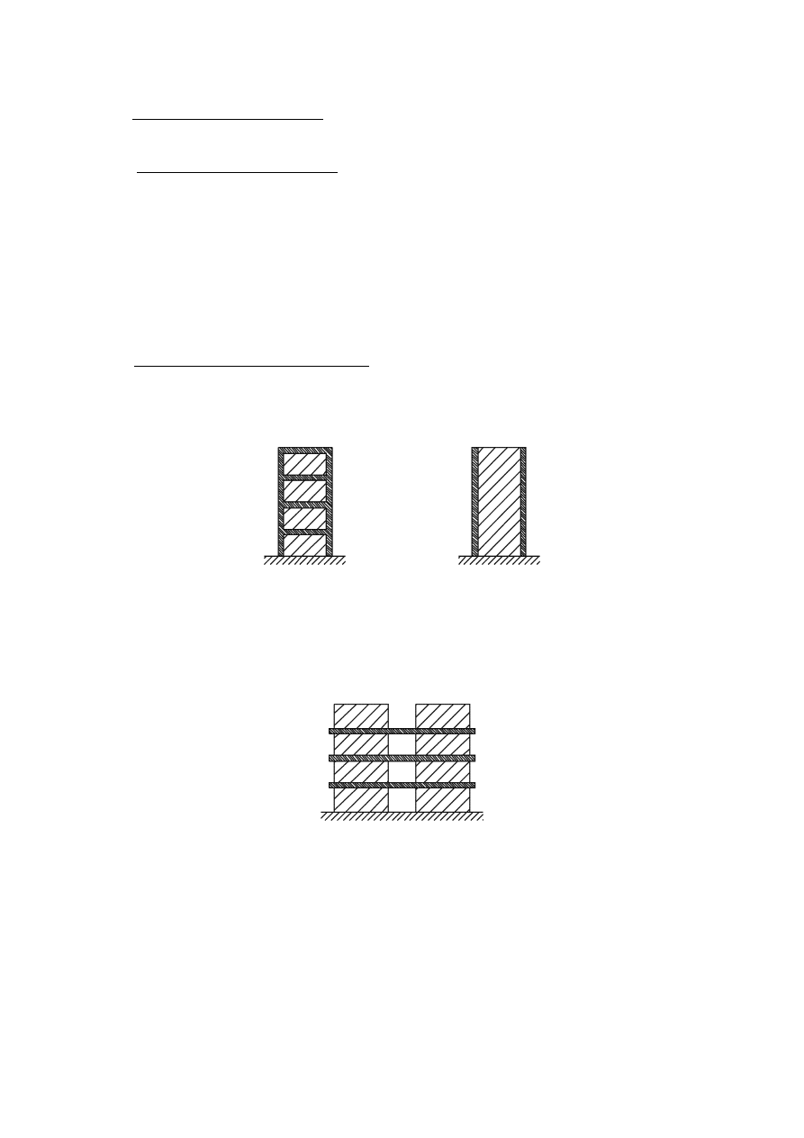
prEN 1998-1:2003 (E)
150
d) Inverted pendulum structures, have the same definition and limitations as in 6.3.1(1)d
(see Figure 6.5);
e) Composite structural systems are those which behave essentially as reinforced
concrete walls. The composite systems may belong to one of the following types:
− Type 1 corresponds to a steel or composite frame working together with concrete
infill panels connected to the steel structure (see Figure 7.1a);
− Type 2 is a reinforced concrete wall in which encased steel sections connected to the
concrete structure are used as vertical edge reinforcement (see Figure 7.1b);
− Type 3, steel or composite beams are used to couple two or more reinforced
concrete or composite walls (see Figure 7.2);
f) Composite steel plate shear walls are those consisting of a vertical steel plate
continuous over the height of the building with reinforced concrete encasement on one
or both faces of the plate and of the structural steel or composite boundary members.
a)
b)
Figure 7.1: Composite structural systems. Composite walls: a) Type 1 – steel or
composite moment frame with connected concrete infill panels; b) Type 2 –
composite walls reinforced by connected encased vertical steel sections.
Figure 7.2: Composite structural systems. Type 3 - composite or concrete walls
coupled by steel or composite beams.
(2)
In all types of composite structural systems the energy dissipation takes place in
the vertical steel sections and in the vertical reinforcements of the walls. In type 3
composite structural systems, energy dissipation may also take place in the coupling
beams;
(3)
If, in composite structural systems the wall elements are not connected to the
steel structure, Sections 5 and 6 apply.

prEN 1998-1:2003 (E)
151
7.3.2 Behaviour
factors
(1)
The behaviour factor q, introduced in 3.2.2.5, accounts for the energy dissipation
capacity of the structure. For regular structural systems, the behaviour factor q should
be taken with upper limits to the reference value which are given in Table 6.2 or in
Table 7.2, provided that the rules in 7.5 to 7.11 are met.
Table 7.2: Upper limits to reference values of behaviour factors for systems
regular elevation
Ductility Class
STRUCTURAL TYPE
DCM DCH
a), b), c) and d)
See Table 6.2
e) Composite structural systems
Composite walls (Type 1 and Type 2)
3
α
u
/
α
1
4
α
u
/
α
1
Composite or concrete walls coupled by steel
or composite beams (Type 3)
3
α
u
/
α
1
4,5
α
u
/
α
1
f) Composite steel plate shear walls
3
α
u
/
α
1
4
α
u
/
α
1
(2)
If the building is non-regular in elevation (see 4.2.3.3) the values of q listed in
Table 6.2 and Table 7.2 should be reduced by 20 % (see 4.2.3.1(7) and Table 4.1).
(3)
For buildings that are regular in plan, if calculations to evaluate
α
u
/
α
1
(see
6.3.2(3)), are not performed, the approximate default values of the ratio
α
u
/
α
1
presented
in Figures 6.1 to 6.8 may be used. For composite structural systems the default value
may be taken as being
α
u
/
α
1
= 1,1. For composite steel plate shear walls the default
value may be taken as being
α
u
/
α
1
= 1,2.
(4)
For buildings which are not regular in plan (see 4.2.3.2), the approximate value
of
α
u
/
α
1
that may be used when calculations are not performed for its evaluation are
equal to the average of (a) 1,0 and of (b) the value given in (3) of this subclause.
(5) Values
of
α
u
/
α
1
higher than those given in (3) and (4) of this subclause are
allowed, provided that they are confirmed by calculating
α
u
/
α
1
with a nonlinear static
(pushover) global analysis.
(6)
The maximum value of
α
u
/
α
1
that may be used in the design is equal to 1,6, even
if the analysis mentioned in (5) of this subclause indicates higher potential values.
7.4 Structural
analysis
7.4.1 Scope
(1)
The following rules apply to the analysis of the structure under earthquake
action with the lateral force analysis method and with the modal response spectrum
analysis method.

prEN 1998-1:2003 (E)
152
7.4.2 Stiffness
of
sections
(1)
The stiffness of composite sections in which the concrete is in compression
should be computed using a modular ratio n
n = E
a
/ E
cm
= 7
(7.1)
(2)
For composite beams with slab in compression, the second moment of area of
the section, referred to as I
1
, should be computed taking into account the effective width
of slab defined in 7.6.3.
(3)
The stiffness of composite sections in which the concrete is in tension should be
computed assuming that the concrete is cracked and that only the steel parts of the
section are active.
(4)
For composite beams with slab in tension, the second moment of area of the
section, referred to as I
2
, should be computed taking into account the effective width of
slab defined in 7.6.3.
(5)
The structure should be analysed taking into account the presence of concrete in
compression in some zones and concrete in tension in other zones; the distribution of
the zones is given in 7.7 to 7.11 for the various structural types.
7.5 Design criteria and detailing rules for dissipative structural behaviour
common to all structural types
7.5.1 General
(1)
The design criteria given in 7.5.2 should be applied to the earthquake-resistant
parts of structures designed in accordance with the concept of dissipative structural
behaviour.
(2)
The design criteria given in 7.5.2 are deemed to be satisfied, if the rules given in
7.5.3 and 7.5.4 and in 7.6 to 7.11 are observed.
7.5.2 Design criteria for dissipative structures
(1)P Structures with dissipative zones shall be designed such that yielding or local
buckling or other phenomena due to hysteretic behaviour in those zones do not affect
the overall stability of the structure.
NOTE The q factors given in Table 7.2 are deemed to conform to this requirement (see 2.2.2(2)).
(2)P Dissipative zones shall have adequate ductility and resistance. The resistance
shall be determined in accordance with EN 1993 and Section 6 for concept c) (see 7.1.2)
and to EN 1994-1-1:2004 and Section 7 for concept b) (see 7.1.2). Ductility is achieved
by compliance to detailing rules.
(3)
Dissipative zones may be located in the structural members or in the
connections.

prEN 1998-1:2003 (E)
153
(4)P If dissipative zones are located in the structural members, the non-dissipative
parts and the connections of the dissipative parts to the rest of the structure shall have
sufficient overstrength to allow the development of cyclic yielding in the dissipative
parts.
(5)P When dissipative zones are located in the connections, the connected members
shall have sufficient overstrength to allow the development of cyclic yielding in the
connections.
7.5.3 Plastic resistance of dissipative zones
(1)P Two
plastic
resistances
of dissipative zones are used in the design of composite
steel - concrete structures: a lower bound plastic resistance (index: pl, Rd) and an upper
bound plastic resistance (index: U, Rd).
(2)P The lower bound plastic resistance of dissipative zones is the one taken into
account in design checks concerning sections of dissipative elements; e.g. M
Ed
< M
pl,Rd
.
The lower bound plastic resistance of dissipative zones is computed taking into account
the concrete component of the section and only the steel components of the section
which are classified as ductile.
(3)P The upper bound plastic resistance of dissipative zones is the one used in the
capacity design of elements adjacent to the dissipative zone: for instance in the capacity
design verification of 4.4.2.3(4), the design values of the moments of resistance of
beams are the upper bound plastic resistances, M
U,Rd,b
, whereas those of the columns are
the lower bound ones, M
pl,Rd,c
.
(4)P The upper bound plastic resistance is computed taking into account the concrete
component of the section and all the steel components present in the section, including
those that are not classified as ductile.
(5)P Action effects, which are directly related to the resistance of dissipative zones,
shall be determined on the basis of the upper bound resistance of composite dissipative
sections; e.g. the design shear force at the end of a dissipative composite beam shall be
determined on the basis of the upper bound plastic moment of the composite section.
7.5.4 Detailing rules for composite connections in dissipative zones
(1)P The design shall limit localization of plastic strains and high residual stresses
and prevent fabrication defects.
(2)P The integrity of the concrete in compression shall be maintained during the
seismic event and yielding shall be limited to the steel sections.
(3)
Yielding of the reinforcing bars in a slab should be allowed only if beams are
designed to conform to 7.6.2(8).
(4)
For the design of welds and bolts, 6.5 applies.
(5)
The local design of the reinforcing bars needed in the concrete of the joint region
should be justified by models that satisfy equilibrium (e.g. Annex C for slabs).

prEN 1998-1:2003 (E)
154
(6)
6.5.5(6), 6.5.5(7) and Note 1 to 6.5.5 apply.
(7)
In fully encased framed web panels of beam/column connections, the panel zone
resistance may be computed as the sum of contributions from the concrete and steel
shear panel, if all the following conditions are satisfied:
a) the aspect ratio h
b
/h
c
of the panel zone is:
0,6 < h
b
/h
c
< 1,4
(7.2)
b) V
wp,Ed
< 0,8 V
wp,Rd
(7.3)
where
V
wp,Ed
is the design shear force in the web panel due to the action effects, taking into
account the plastic resistance of the adjacent composite dissipative zones in
beams or connections;
V
wp,Rd
is the shear resistance of the composite steel - concrete web panel in accordance
with EN 1994-1-1:2004;
h
b
, h
c
are as defined in Figure 7.3a).
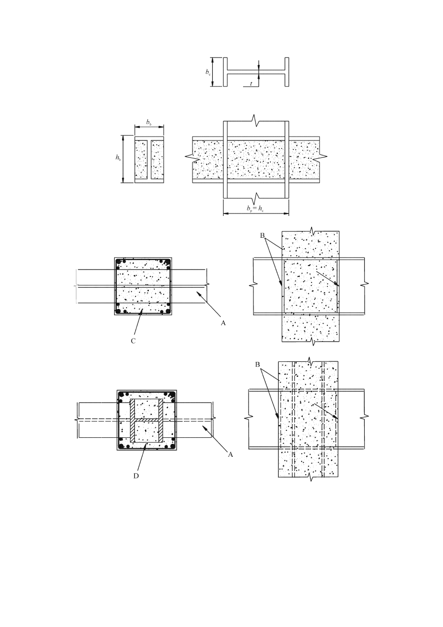
prEN 1998-1:2003 (E)
155
a)
b)
c)
Key
A
steel beam;
B
face bearing plates;
C
reinforced concrete column;
D
composite encased column
Figure 7.3: Beam column connections.

prEN 1998-1:2003 (E)
156
(8)
In partially encased stiffened web panels, an assessment similar to that in (7) of
this subclause is permitted if, in addition to the requirements of (9), one of the following
conditions is fulfilled:
a) straight links of the type defined in 7.6.5(4) and complying with 7.6.5(5) and (6) are
provided at a maximum spacing s
1
= c in the partially encased stiffened web panel;
these links are oriented perpendicularly to the longest side of the column web panel and
no other reinforcement of the web panel is required; or
b) no reinforcement is present, provided that h
b
/b
b
< 1,2 and h
c
/b
c
< 1,2
where h
b
, b
b
, b
c
and h
c
are as defined in Figure 7.3a).
(9)
When a dissipative steel or composite beam is framing into a reinforced concrete
column as shown in Figure 7.3b), vertical column reinforcement with design axial
strength at least equal to the shear strength of the coupling beam should be placed close
to the stiffener or face bearing plate adjacent to the dissipative zone. It is permitted to
use vertical reinforcement placed for other purposes as part of the required vertical
reinforcement. The presence of face bearing plates is required; they should be full depth
stiffeners of a combined width not less than (b
b
– 2 t); their thickness should be not less
than 0,75 t or 8 mm; b
b
and t are respectively the beam flange width and the panel web
thickness (see Figure 7.3).
(10) When a dissipative steel or composite beam is framing into a fully encased
composite column as shown at Figure 7.3c), the beam column connection may be
designed either as a beam/steel column connection or a beam/composite column
connection. In the latter case, vertical column reinforcements may be calculated either
as in (9) of this subclause or by distributing the shear strength of the beam between the
column steel section and the column reinforcement. In both instances, the presence of
face bearing plates as described in (9) is required.
(11) The vertical column reinforcement specified in (9) and (10) of this subclause
should be confined by transverse reinforcement that meets the requirements for
members defined in 7.6.
7.6 Rules for members
7.6.1 General
(1)P Composite members, which are primary seismic members, shall conform to EN
1994-1-1:2004 and to additional rules defined in this Section.
(2)P The earthquake resistant structure is designed with reference to a global plastic
mechanism involving local dissipative zones; this global mechanism identifies the
members in which dissipative zones are located and indirectly the members without
dissipative zones.
(3)
For tension members or parts of members in tension, the ductility requirement of
EN 1993-1-1:2004, 6.2.3(3) should be met.

prEN 1998-1:2003 (E)
157
(4)
Sufficient local ductility of members which dissipate energy under compression
and/or bending should be ensured by restricting the width-to-thickness ratios of their
walls. Steel dissipative zones and the not encased steel parts of composite members
should meet the requirements of 6.5.3(1) and Table 6.3. Dissipative zones of encased
composite members should meet the requirements of Table 7.3. The limits given for
flange outstands of partially or fully encased members may be relaxed if special details
are provided as described in 7.6.4(9) and 7.6.5(4) to (6).
Table 7.3: Relation between behaviour factor and limits of wall slenderness.
Ductility Class of Structure
DCM
DCH
Reference value of behaviour
factor (q)
q
≤ 1,5 - 2 1,5 -2 < q < 4
q > 4
Partially Encased H or I Section
Fully Encased H or I Section
flange outstand limits c/t
f
:
20
ε
14
ε
9
ε
Filled Rectangular Section
h/t limits:
52
ε 38
ε 24
ε
Filled Circular Section
d/t limits:
90
ε
2
85
ε
2
80
ε
2
where
ε = (f
y
/235)
0,5
c/t
f
is as defined in Figure 7.8
d/t and h/t are the ratio between the maximum external dimension and the wall
thickness
(5)
More specific detailing rules for composite members are given in 7.6.2, 7.6.4,
7.6.5 and 7.6.6.
(6)
In the design of all types of composite columns, the resistance of the steel
section alone or the combined resistances of the steel section and the concrete
encasement or infill may be taken into account.
(7)
The design of columns in which the member resistance is taken to be provided
only by the steel section may be carried out in accordance with the provisions of Section
6. In the case of dissipative columns, the capacity design rules in 7.5.2(4) and (5) and
7.5.3(3) should be satisfied.
(8)
For fully encased columns with composite behaviour, the minimum cross-
sectional dimensions b, h or d should be not less than 250 mm.
(9)
The resistance, including shear resistance, of non-dissipative composite columns
should be determined in accordance with the rules of EN 1994-1-1:2004.

prEN 1998-1:2003 (E)
158
(10) In columns, when the concrete encasement or infill are assumed to contribute to
the axial and/or flexural resistance of the member, the design rules in 7.6.4 to 7.6.6
apply. These rules ensure full shear transfer between the concrete and the steel parts in a
section and protect the dissipative zones against premature inelastic failure.
(11) For earthquake-resistant design, the design shear strength given in EN 1994-1-
1:2004, Table 6.6, should be multiplied by a reduction factor of 0,5.
(12) When, for capacity design purposes, the full composite resistance of a column is
employed, complete shear transfer between the steel and reinforced concrete parts
should be ensured. If insufficient shear transfer is achieved through bond and friction,
shear connectors should be provided to ensure full composite action.
(13) Wherever a composite column is subjected to predominately axial forces,
sufficient shear transfer should be provided to ensure that the steel and concrete parts
share the loads applied to the column at connections to beams and bracing members.
(14) Except at their base in some structural types, columns are generally not designed
to be dissipative. However, because of uncertainties in the behaviour, confining
reinforcement is required in regions called “critical regions” as specified in 7.6.4.
(15) Subclauses
5.6.2.1 and 5.6.3 concerning anchorage and splices in the design of
reinforced concrete columns apply also to the reinforcements of composite columns.
7.6.2 Steel beams composite with slab
(1)P The design objective of this subclause is to maintain the integrity of the concrete
slab during the seismic event, while yielding takes place in the bottom part of the steel
section and/or in the rebars of the slab.
(2)P If it is not intended to take advantage of the composite character of the beam
section for energy dissipation, 7.7.5 shall be applied.
(3)
Beams intended to behave as composite elements in dissipative zones of the
earthquake resistant structure may be designed for full or partial shear connection in
accordance with EN 1994-1-1:2004. The minimum degree of connection
η as defined in
EN 1994-1-1:2004 6.6.1.2 should be not less than 0,8 and the total resistance of the
shear connectors within any hogging moment region not less than the plastic resistance
of the reinforcement.
(4)
The design resistance of connectors in dissipative zones is obtained from the
design resistance provided in EN 1994-1-1:2004 multiplied by a reduction factor of
0,75.
(5)
Full shear connection is required when non-ductile connectors are used.
(6)
When a profiled steel sheeting with ribs transverse to the supporting beams is
used, the reduction factor k
t
of the design shear resistance of connectors given by EN
1994-1-1 should be further reduced by multiplying it by the rib shape efficiency factor
k
r
given in Figure 7.4.
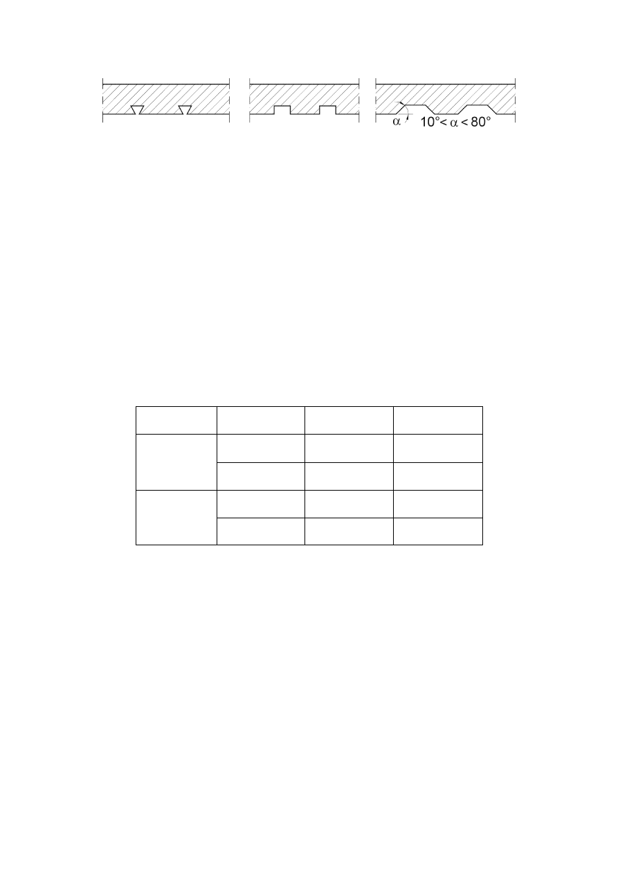
prEN 1998-1:2003 (E)
159
k
r
= 1
k
r
= 1
k
r
= 0,8
Figure 7.4: Values of the rib shape efficiency factor.
(7)
To achieve ductility in plastic hinges, the ratio x/d of the distance x between the
top concrete compression fibre and the plastic neutral axis, to the depth d of the
composite section, should conform to the following expression:
x/d <
ε
cu2
/ (
ε
cu2+
ε
a
) (7.4)
where
ε
cu2
is the ultimate compressive strain of concrete (see EN 1992-1-1:2004);
ε
a
is the total strain in steel at Ultimate Limit State.
(8)
The rule in (7) of this subclause is deemed to be satisfied when x/d of a section
is less than the limits given in Table 7.4.
Table 7.4: Limit values of x/d for ductility of beams with slab
Ductility class
q
f
y
(N/mm
2
)
x/d upper limit
1,5 < q
≤ 4
355 0,27
DCM
1,5 < q
≤ 4
235 0,36
q > 4
355
0,20
DCH
q > 4
235
0,27
(9)
In dissipative zones of beams, specific ductile steel reinforcement of the slab
called “seismic rebars” (see Figure 7.5), should be present in the connection zone of the
beam and the column. Its design and the symbols used in Figure 7.5 are specifed in
Annex C.
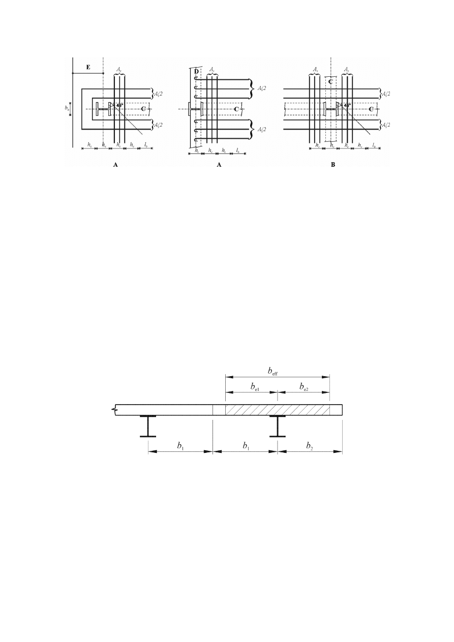
prEN 1998-1:2003 (E)
160
Key
A Exterior
Node
B Interior
Node
C Steel
beam
D
Façade steel beam
E
Reinforced concrete cantilever edge strip
Figure 7.5: Layout of “seismic rebars”
7.6.3 Effective width of slab
(1)
The total effective width b
eff
of concrete flange associated with each steel web
should be taken as the sum of the partial effective widths b
e1
and b
e2
of the portion of
the flange on each side of the centreline of the steel web (Figure 7.6). The partial
effective width on each side should be taken as b
e
given in Table 7.5, but not greater
than the actual available widths b
1
and b
2
defined in (2) of this subclause.
Figure 7.6: Definition of effective width b
e
and b
eff
(2) The
actual
width
b of each portion should be taken as half the distance from the
web to the adjacent web, except that at a free edge the actual width is the distance from
the web to the free edge.
(3)
The partial effective width b
e
of the slab to be used in the determination of the
elastic and plastic properties of the composite T sections made of a steel section
connected to a slab are defined in Table 7.5 and Figure 7.7. These values are valid for
beams positioned as beams C in Figure 7.5 and if the design of the slab reinforcement
and of the connection of the slab to the steel beams and columns are in accordance with
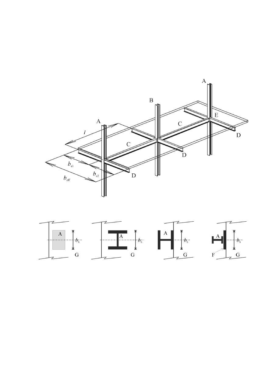
prEN 1998-1:2003 (E)
161
Annex C. In Table 7.5 those moments which induce compression in the slab are
considered as positive and those which induce tension in the slab are considered as
negative. Symbols b
b
, h
c
, b
e
, b
eff
and l used in Tables 7.5 I and 7.5 II are defined in
Figures 7.5, 7.6 and 7.7. b
b
is the bearing width of the concrete of the slab on the
column in the horizontal direction perpendicular to the beam for which the effective
width is computed; this bearing width possibly includes additional plates or devices
aiming at increased bearing capacity.
Key
A Exterior
column;
B Interior
column;
C Longitudinal
beam;
D
Transverse beam or steel façade beam;
E
Cantilever concrete edge strip;
F Extended
bearing;
G Concrete
slab
Figure 7.7: Definition of elements in moment frame structures.

prEN 1998-1:2003 (E)
162
Table 7.5 I: Partial effective width b
e
of slab for elastic analysis of the structure
b
e
Transverse element
b
e
for I (ELASTIC)
At interior column Present or not present
For negative M : 0,05 l
At exterior column Present
For positive M : 0,0375 l
At exterior column
Not present,
or re-bars not anchored
For negative M : 0
For positive M : 0,025 l
Table 7.5 II: Partial effective width b
e
of slab for evaluation of plastic moment
resistance
Sign of bending
moment M
Location Transverse
element
b
e
for M
Rd
(PLASTIC)
Negative M
Interior
column
Seismic re-bars
0,1 l
Negative M
Exterior
column
All layouts with re-bars anchored to façade
beam or to concrete cantilever edge strip
0,1 l
Negative M
Exterior
column
All layouts with re-bars not anchored to
façade beam or to concrete cantilever edge
strip
0,0
Positive M
Interior
column
Seismic re-bars
0,075 l
Positive M
Exterior
column
Steel transverse beam with connectors.
Concrete slab up to exterior face of column
of H section with strong axis oriented as in
Fig. 7.5 or beyond (concrete edge strip).
Seismic re-bars
0,075 l
Positive M
Exterior
column
No steel transverse beam or steel transverse
beam without connectors.
Concrete slab up to exterior face of column
of H section with strong axis oriented as in
Fig. 7.5, or beyond (edge strip).
Seismic re-bars
b
b
/2 +0,7 h
c
/2
Positive M
Exterior
column
All other layouts. Seismic re-bars
b
b
/2
≤ b
e,max
b
e,max
=0,05l
7.6.4 Fully encased composite columns
(1)
In dissipative structures, critical regions are present at both ends of all column
clear lengths in moment frames and in the portion of columns adjacent to links in
eccentrically braced frames. The lengths l
cr
of these critical regions (in metres) are
specified by expression (5.14) for ductility class M, or by expression (5.30) for ductility
class H, with h
c
in these expressions denoting the depth of the composite section (in
metres).
(2)
To satisfy plastic rotation demands and to compensate for loss of resistance due
to spalling of cover concrete, the following expression should be satisfied within the
critical regions defined above:

prEN 1998-1:2003 (E)
163
α
.
ω
wd
≥ 30
.
µ
φ
035
,
0
o
c
d
sy,
d
−
⋅
⋅
⋅
b
b
ε
ν
(7.5)
in which the variables are as defined in 5.4.3.2.2(8) and the normalised design axial
force
ν
d
is defined as:
ν
d
= N
Ed
/N
pl,Rd
= N
Ed
/(A
a
f
yd
+ A
c
f
cd
+ A
s
f
sd
) (7.6)
(3) The
spacing,
s, (in millimetres) of confining hoops in critical regions should not
exceed
s = min(b
o
/2, 260, 9 d
bL
) in ductility class DCM;
(7.7)
s = min(b
o
/2, 175, 8 d
bL
) in ductility class DCH
(7.8)
or at the lower part of the lower storey, in ductility class DCH
s = min(b
o
/2, 150, 6d
bL
) (7.9)
where
b
o
is the minimum dimension of the concrete core (to the centreline of the hoops, in
millimetres);
d
bL
is the
minimum diameter of the longitudinal rebars (in millimetres).
(4)
The diameter of the hoops, d
bw
, (in millimetres) should be at least
d
bw
= 6 in ductility class DCM
(7.10)
d
bw
= max( 0,35 d
bL,max
[f
ydL
/f
ydw
]
0,5
, 6) in ductility class DCH
(7.11)
where
d
bL,max
is the
maximum diameter of the longitudinal rebars (in millimetres).
(5)
In critical regions, the distance between consecutive longitudinal bars restrained
by hoop bends or cross-ties should not exceed 250 mm in ductility class DCM or 200
mm in ductility class DCH.
(6)
In the lower two storeys of a building, hoops in accordance with (3), (4) and (5)
should be provided beyond the critical regions for an additional length equal to half the
length of the critical regions.
(7)
In dissipative composite columns, the shear resistance should be determined on
the basis of the structural steel section alone.
(8)
The relationship between the ductility class of the structure and the allowable
slenderness (c/t
f
) of the flange outstand in dissipative zones is given in Table 7.3.
(9)
Confining hoops can delay local buckling in the dissipative zones. The limits
given in Table 7.3 for flange slenderness may be increased if the hoops are provided at a
longitudinal spacing, s, which is less than the flange outstand: s/c < 1,0. For s/c < 0,5

prEN 1998-1:2003 (E)
164
the limits given in Table 7.3 may be increased by up to 50%. For values of 0,5 < s/c <
1,0 linear interpolation may be used.
(10) The
diameter
d
bw
of confining hoops used to prevent flange buckling should be
not less than
(
)
(
)
[
]
5
,
0
ydw
ydf
f
bw
/
8
/
f
f
t
b
d
⋅
=
(7.12)
in which b
and t
f
are the width and thickness of the flange respectively and f
ydf
and f
ydw
are the design yield strengths of the flange and reinforcement respectively.
7.6.5 Partially-encased
members
(1)
In dissipative zones where energy is dissipated by plastic bending of a
composite section, the longitudinal spacing of the transverse reinforcement, s, should
satisfy the requirements of 7.6.4(3) over a length greater or equal to l
cr
for dissipative
zones at the end of a member and 2l
cr
for dissipative zones in the member.
(2)
In dissipative members, the shear resistance should be determined on the basis
of the structural steel section alone, unless special details are provided to mobilise the
shear resistance of the concrete encasement.
(3)
The relationship between the ductility class of the structure and the allowable
slenderness (c/t) of the flange outstand in dissipative zones is given in Table 7.3.
Key
A
Additional straight bars (links)
Figure 7.8: Detail of transverse reinforcement, with the additional straight bars
(links) welded to the flanges.
(4)
Straight links welded to the inside of the flanges, as shown in Figure 7.8,
additional to the reinforcements required by EN 1994-1-1, can delay local buckling in
the dissipative zones. In this case, the limits given in Table 7.3 for flange slenderness
may be increased if these bars are provided at a longitudinal spacing, s
1
. which is less
than the flange outstand: s
1
/c < 1,0. For s
1
/c < 0,5 the limits given in Table 7.3 may be
increased by up to 50%. For values of 0,5 < s
1
/c < 1,0 linear interpolation may be used.

prEN 1998-1:2003 (E)
165
The additional straight links should also conform to the rules in (5) and (6) of this
subclause.
(5) The
diameter,
d
bw,
of the additional straight links referred to in (4) of this
subclause should be at least 6 mm. When transverse links are employed to delay local
flange buckling as described in (4), d
bw
should be not less than the value given by
expression (7.12).
(6)
The additional straight links referred to in (4) should be welded to the flanges at
both ends and the capacity of the welds should be not less than the tensile yield strength
of the straight links. A clear concrete cover of at least 20 mm, but not exceeding 40 mm,
should be provided to these links.
(7)
The design of partially-encased composite members may take into account the
resistance of the steel section alone, or the composite resistance of the steel section and
of concrete encasement.
(8)
The design of partially-encased members in which only the steel section is
assumed to contribute to member resistance may be carried out in accordance with the
provisions of Section 6, but the capacity design provisions of 7.5.2(4) and (5) and
7.5.3(3) should be applied.
7.6.6 Filled Composite Columns
(1)
The relationship between the ductility class of the structure and the allowable
slenderness d/t or h/t is given in Table 7.3.
(2)
The shear resistance of dissipative columns should be determined on the basis of
the structural steel section or on the basis of the reinforced concrete section with the
steel hollow section taken only as shear reinforcement.
(3) In
non-dissipative members, the shear resistance of the column should be
determined in accordance with EN 1994-1-1.
7.7 Design and detailing rules for moment frames
7.7.1 Specific
criteria
(1)P 6.6.1(1)P applies.
(2)P The composite beams shall be designed for ductility and so that the integrity of
the concrete is maintained.
(3)
Depending on the location of the dissipative zones, either 7.5.2(4) or 7.5.2(5)
applies.
(4)
The required hinge formation pattern should be achieved by observing the rules
given in 4.4.2.3, 7.7.3, 7.7.4 and 7.7.5.

prEN 1998-1:2003 (E)
166
7.7.2 Analysis
(1)P The analysis of the structure shall be performed on the basis of the section
properties defined in 7.4.
(2)
In beams, two different flexural stiffnesses should be taken into account: EI
1
for
the part of the spans submitted to positive (sagging) bending (uncracked section) and
EI
2
for the part of the span submitted to negative (hogging) bending (cracked section).
(3)
The analysis may alternatively be performed taking into account for the entire
beam an equivalent second moment of area I
eq
constant for the entire span:
I
eq
= 0,6 I
1
+ 0,4 I
2
(7.13)
(4)
For composite columns, the flexural stiffness is given by:
(EI)
c
= 0,9( EI
a
+ r E
cm
I
c
+ E I
s
)
(7.14)
where
E and E
cm
are the modulus of elasticity for steel and concrete respectively;
r
is the reduction factor depending on the type of column cross-section;
I
a
, I
c
and I
s
denote the second moment of area of the steel section, of the concrete
and of the rebars respectively.
NOTE The value ascribed to r for use in a country may be found in its National Annex of this
document. The recommended value is r = 0,5.
7.7.3 Rules for beams and columns
(1)P Composite T beam design shall conform to 7.6.2. Partially encased beams shall
conform to 7.6.5.
(2)P Beams shall be verified for lateral and lateral torsional buckling in accordance
with EN 1994-1-1, assuming the formation of a negative plastic moment at one end of
the beam.
(3)
6.6.2(2) applies.
(4)
Composite trusses should not be used as dissipative beams.
(5)P 6.6.3(1)P applies.
(6)
In columns where plastic hinges form as stated in 7.7.1(1), the verification
should assume that M
pl,Rd
is realised in these plastic hinges.
(7)
The following expression should apply for all composite columns:
N
Ed
/N
pl,Rd
< 0,30
(7.15)
(8)
The resistance verifications of the columns should be made in accordance with
EN 1994-1-1:2004, 4.8.

prEN 1998-1:2003 (E)
167
(9)
The column shear force V
Ed
(from the analysis) should be limited in accordance
with expression (6.4).
7.7.4 Beam to column connections
(1)
The provisions given in 6.6.4 apply.
7.7.5 Condition for disregarding the composite character of beams with slab.
(1)P The plastic resistance of a beam section composite with slab (lower or upper
bound plastic resistance of dissipative zones) may be computed taking into account only
the steel section (design in accordance with concept c) as defined in 7.1.2) if the slab is
totally disconnected from the steel frame in a circular zone around a column of diameter
2b
eff
, with b
eff
being the larger of the effective widths of the beams connected to that
column.
(2)
For the purposes of (1)P, "totally disconnected" means that there is no contact
between slab and any vertical side of any steel element (e.g. columns, shear connectors,
connecting plates, corrugated flange, steel deck nailed to flange of steel section).
(3)
In partially encased beams, the contribution of concrete between the flanges of
the steel section should be taken into account.
7.8 Design and detailing rules for composite concentrically braced frames
7.8.1 Specific
criteria
(1)P 6.7.1(1)P applies.
(2)P Columns and beams shall be either structural steel or composite.
(3)P Braces
shall
be
structural steel.
(4)
6.7.1(2)P applies
7.8.2 Analysis
(1)
The provisions given in 6.7.2 apply.
7.8.3 Diagonal
members
(1)
The provisions given in 6.7.3 apply.
7.8.4 Beams and columns
(1)
The provisions given in 6.7.4 apply.

prEN 1998-1:2003 (E)
168
7.9 Design and detailing rules for composite eccentrically braced frames
7.9.1 Specific
criteria
(1)P Composite frames with eccentric bracings shall be designed so that the
dissipative action will occur essentially through yielding in shear of the links. All other
members shall remain elastic and failure of connections shall be prevented.
(2)P Columns, beams and braces shall be either structural steel or composite.
(3)P The braces, columns and beam segments outside the link segments shall be
designed to remain elastic under the maximum forces that can be generated by the fully
yielded and cyclically strain-hardened beam link.
(4)P 6.8.1(2)P applies.
7.9.2 Analysis
(1)P The analysis of the structure is based on the section properties defined in 7.4.2.
(2)
In beams, two different flexural stiffnesses are taken into account: EI
1
for the
part of the spans submitted to positive (sagging) bending (uncracked section) and EI
2
for the part of the span submitted to negative (hogging) bending (cracked section).
7.9.3 Links
(1)P Links shall be made of steel sections, possibly composite with slabs. They may
not be encased.
(2)
The rules on seismic links and their stiffeners given in 6.8.2 apply. Links should
be of short or intermediate length with a maximum length e:
− In structures where two plastic hinges would form at link ends
e = 2M
p, link
/ V
p, link.
(7.16)
− In structures where one plastic hinge would form at one end of a link
e < M
p, link
/ V
p, link
(7.17)
The definitions of M
p,link
and V
p
,
link
are given in 6.8.2(3). For M
p,link
, only the steel
components of the link section, disregarding the concrete slab, are taken into account in
the evaluation.
(3)
When the seismic link frames into a reinforced concrete column or an encased
column, face bearing plates should be provided on both sides of the link at the face of
the column and in the end section of the link. These bearing plates should conform to
7.5.4.
(4)
The design of beam/column connections adjacent to dissipative links should
conform to 7.5.4.

prEN 1998-1:2003 (E)
169
(5)
Connections should meet the requirements of the connections of eccentrically
braced steel frames as in 6.8.4.
7.9.4 Members not containing seismic links
(1)
The members not containing seismic links should conform to the rules in 6.8.3,
taking into account the combined resistance of steel and concrete in the case of
composite elements and the relevant rules for members in 7.6 and in EN 1994-1-1:2004.
(2)
Where a link is adjacent to a fully encased composite column, transverse
reinforcement meeting the requirements of 7.6.5 should be provided above and below
the link connection.
(3)
In case of a composite brace under tension, only the cross-section of the
structural steel section should be taken into account in the evaluation of the resistance of
the brace.
7.10 Design and detailing rules for structural systems made of reinforced concrete
shear walls composite with structural steel elements
7.10.1 Specific criteria
(1)P The provisions in this subclause apply to composite structural systems belonging
in one of the three types defined in 7.3.1e.
(2)P Structural system types 1 and 2 shall be designed to behave as shear walls and
dissipate energy in the vertical steel sections and in the vertical reinforcement. The
infills shall be tied to the boundary elements to prevent separation.
(3)P In structural system type 1, the storey shear forces shall be carried by horizontal
shear in the wall and in the interface between the wall and beams.
(4)P Structural system type 3 shall be designed to dissipate energy in the shear walls
and in the coupling beams.
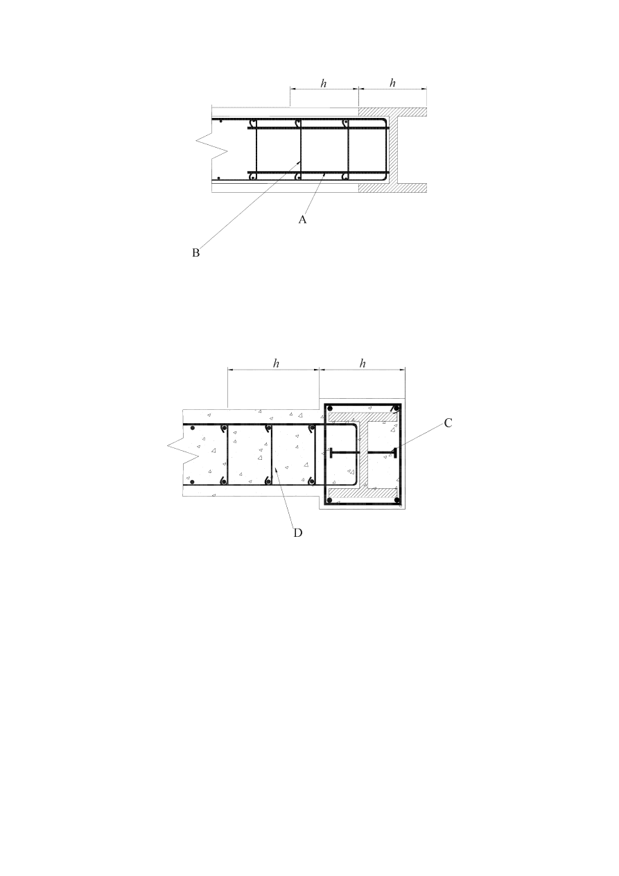
prEN 1998-1:2003 (E)
170
Key
A
bars welded to column;
B transverse
reinforcement
Figure 7.9a: Details of partially encased composite boundary elements (details of
transverse reinforcements are for ductility class DCH).
Key
C = shear connectors;
D = cross tie
Figure 7.9b: Details of fully encased composite boundary elements (details of
transverse reinforcements are for ductility class DCH).
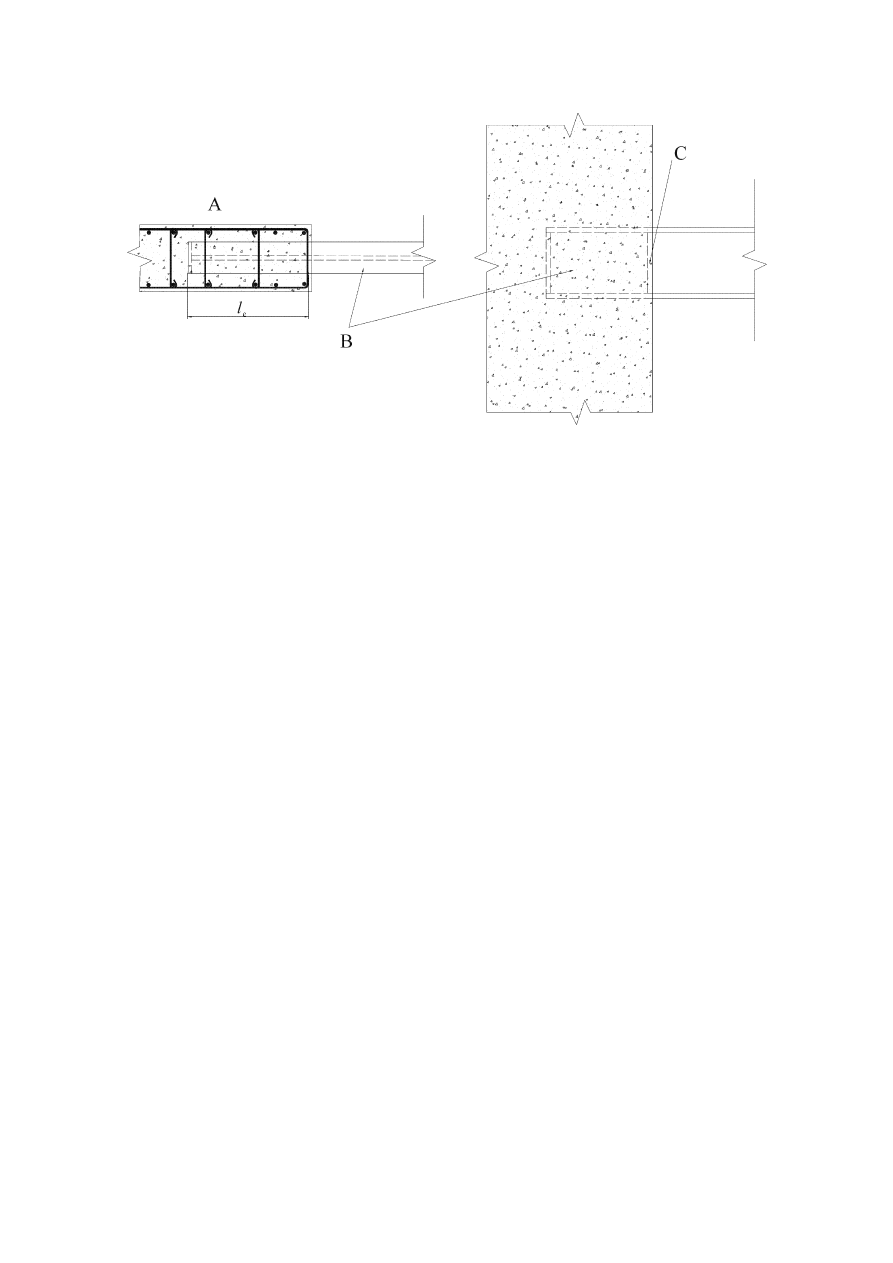
prEN 1998-1:2003 (E)
171
Key
A Additional
wall
reinforcement
at embedment of steel beam;
B
Steel coupling beam;
C
Force bearing plate
Figure 7.10: Details of coupling beam framing into a wall (details are for ductility
class DCH
7.10.2 Analysis
(1)P The analysis of the structure shall be based on the section properties defined in
Section 5 for concrete walls and in 7.4.2 for composite beams.
(2)P In structural systems of type 1 or type 2, when vertical fully encased or partially
encased structural steel sections act as boundary members of reinforced concrete infill
panels, the analysis shall be made assuming that the seismic action effects in these
vertical boundary elements are axial forces only.
(3)
These axial forces should be determined assuming that the shear forces are
carried by the reinforced concrete wall and that the entire gravity and overturning forces
are carried by the shear wall acting composedly with the vertical boundary members.
(4)
In structural system of type 3, if composite coupling beams are used, 7.7.2(2)
and (3) apply.
7.10.3 Detailing rules for composite walls of ductility class DCM
(1)P The reinforced concrete infill panels in Type 1 and the reinforced concrete walls
in Types 2 and 3 shall meet the requirements of Section 5 for ductile walls of DCM.
(2)P Partially encased steel sections used as boundary members of reinforced
concrete panels shall belong to a class of cross-section related to the behaviour factor of
the structure as indicated in Table 7.3.

prEN 1998-1:2003 (E)
172
(3)P Fully encased structural steel sections used as boundary members in reinforced
concrete panels shall be designed in accordance with 7.6.4.
(4)P Partially encased structural steel sections used as boundary members of
reinforced concrete panels shall be designed in accordance with 7.6.5.
(5)
Headed shear studs or tie reinforcement (welded to, anchored through holes in
the steel members or anchored around the steel member) should be provided to transfer
vertical and horizontal shear forces between the structural steel of the boundary
elements and the reinforced concrete.
7.10.4 Detailing rules for coupling beams of ductility class DCM
(1)P Coupling beams shall have an embedment length into the reinforced concrete
wall sufficient to resist the most adverse combination of moment and shear generated by
the bending and shear strength of the coupling beam. The embedment length l
e
shall be
taken to begin inside the first layer of the confining reinforcement in the wall boundary
member (see Figure 7.10). The embedment length l
e
shall be not less than 1,5 times the
height of the coupling beam
(2)P The design of beam/wall connections shall conform to 7.5.4.
(3)
The vertical wall reinforcements, defined in 7.5.4(9) and (10) with design axial
strength equal to the shear strength of the coupling beam, should be placed over the
embedment length of the beam with two-thirds of the steel located over the first half of
the embedment length. This wall reinforcement should extend a distance of at least one
anchorage length above and below the flanges of the coupling beam. It is permitted to
use vertical reinforcement placed for other purposes, such as for vertical boundary
members, as part of the required vertical reinforcement. Transverse reinforcement
should conform to 7.6.
7.10.5 Additional detailing rules for ductility class DCH.
(1)P Transverse reinforcement for confinement of the composite boundary members,
either partially or fully encased, shall be used. Reinforcement shall extend to a distance
of 2h into the concrete walls where h is the depth of the boundary element in the plane
of the wall (see Figure 7.9a) and b)).
(2)P The requirements for the links in frames with eccentric bracings apply to the
coupling beams.
7.11 Design and detailing rules for composite steel plate shear walls
7.11.1 Specific criteria
(1)P Composite steel plate shear walls shall be designed to yield through shear of the
steel plate.
(2)
The steel plate should be stiffened by one or two sided concrete encasement and
attachment to the reinforced concrete encasement in order to prevent buckling of steel.

prEN 1998-1:2003 (E)
173
7.11.2 Analysis
(1)
The analysis of the structure should be based on the materials and section
properties defined in 7.4.2 and 7.6.
7.11.3 Detailing rules
(1)P It shall be checked that
V
Ed
< V
Rd
(7.18)
with the shear resistance given by:
3
/
yd
pl
Rd
f
A
V
×
=
(7.19)
where
f
yd
is the design yield strength of the plate; and
A
pl
is the horizontal area of the plate.
(2)P The connections between the plate and the boundary members (columns and
beams), as well as the connections between the plate and the concrete encasement, shall
be designed such that full yield strength of the plate can be developed.
(3)P The steel plate shall be continuously connected on all edges to structural steel
framing and boundary members with welds and/or bolts to develop the yield strength of
the plate in shear.
(4)P The boundary members shall be designed to meet the requirements of 7.10.
(5)
The concrete thickness should be not less than 200 mm when it is provided on
one side and 100 mm on each side when provided on both sides.
(6)
The minimum reinforcement ratio in both directions shall be not less than
0,25%.
(7)
Openings in the steel plate shall be stiffened as required by analysis.
7.12 Control of design and construction
(1)
For the control of design and construction, 6.11 applies.

prEN 1998-1:2003 (E)
174
8 SPECIFIC RULES FOR TIMBER BUILDINGS
8.1 General
8.1.1 Scope
(1)P For the design of timber buildings EN 1995 applies. The following rules are
additional to those given in EN 1995.
8.1.2 Definitions
(1)P The following terms are used in this section with the following meanings:
static ductility
ratio between the ultimate deformation and the deformation at the end of elastic
behaviour evaluated in quasi-static cyclic tests (see 8.3(3)P);
semi-rigid joints
joints with significant flexibility, the influence of which has to be taken into account in
structural analysis in accordance with EN 1995 (e.g. dowel-type joints);
rigid joints
joints with negligible flexibility in accordance with EN 1995 (e.g. glued solid timber
joints);
Dowel-type joints
joints with dowel-type mechanical fasteners (nails, staples, screws, dowels, bolts etc.)
loaded perpendicular to their axis;
Carpenter joints
joints, where loads are transferred by means of pressure areas and without mechanical
fasteners (e.g. skew notch, tenon, half joint).
8.1.3 Design
concepts
(1)P Earthquake-resistant timber buildings shall be designed in accordance with one
of the following concepts:
a) dissipative structural behaviour;
b) low-dissipative structural behaviour.
(2)
In concept a) the capability of parts of the structure (dissipative zones) to resist
earthquake actions out of their elastic range is taken into account. When using the
design spectrum defined in 3.2.2.5, the behaviour factor q may be taken as being greater
than 1,5. The value of q depends on the ductility class (see 8.3).
(3)P Structures designed in accordance with concept a) shall belong to structural
ductility classes M or H. A structure belonging to a given ductility class shall meet
specific requirements in one or more of the following aspects: structural type, type and
rotational ductility capacity of connections.

prEN 1998-1:2003 (E)
175
(4)P Dissipative zones shall be located in joints and connections, whereas the timber
members themselves shall be regarded as behaving elastically.
(5)
The properties of dissipative zones should be determined by tests either on
single joints, on whole structures or on parts thereof in accordance with prEN 12512.
(6)
In concept b) the action effects are calculated on the basis of an elastic global
analysis without taking into account non-linear material behaviour. When using the
design spectrum defined in 3.2.2.5, the behaviour factor q should not be taken greater
than 1,5. The resistance of the members and connections should be calculated in
accordance with EN 1995-1:2004 without any additional requirements. This concept is
termed ductility class L (low) and is appropriate only for certain structural types (see
Table 8.1).
8.2 Materials and properties of dissipative zones
(1)P The relevant provisions of EN 1995 apply. With respect to the properties of steel
elements, EN 1993 applies.
(2)P When using the concept of dissipative structural behaviour, the following
provisions apply:
a) only materials and mechanical fasteners providing appropriate low cycle fatigue
behaviour may be used in joints regarded as dissipative zones;
b) glued joints shall be considered as non-dissipative zones;
c) carpenter joints may only be used when they can provide sufficient energy dissipation
capacity, without presenting risks of brittle failure in shear or tension perpendicular to
the grain. The decision on their use shall be based on appropriate test results.
(3)
(2)P a) of this subclause is deemed to be satisfied if 8.3(3)P is fulfilled.
(4) For
sheathing-material
in
shear walls and diaphragms, (2)P a) is deemed to be
satisfied, if the following conditions are met:
a) particleboard-panels have a density of at least 650 kg/m
3
;
b) plywood-sheathing is at least 9 mm thick;
c) particleboard - and fibreboard-sheathing are at least 13 mm thick.
(5)P Steel material for connections shall conform to the following conditions:
a) all connection elements made of cast steel shall fulfil the relevant requirements in EN
1993;
b) The ductility properties of the connections in trusses and between the sheathing
material and the timber framing in Ductility Class M or H structures (see (8.3)) shall be
tested for compliance with 8.3(3)P by cyclic tests on the relevant combination of the
connected parts and fastener.

prEN 1998-1:2003 (E)
176
8.3 Ductility classes and behaviour factors
(1)P Depending on their ductile behaviour and energy dissipation capacity under
seismic actions, timber buildings shall be assigned to one of the three ductility classes
L, M or H as given in Table 8.1, where the corresponding upper limit values of the
behaviour factors are also given.
NOTE Geographical limitations on the use of ductility classes M and H may be found in the
relevant National Annex.
Table 8.1: Design concept, Structural types and upper limit values of the
behaviour factors for the three ductility classes.
Design concept and
ductility class
q
Examples of structures
Low capacity to dissipate
energy - DCL
1,5 Cantilevers; Beams; Arches with two or three
pinned joints; Trusses joined with connectors.
2
Glued wall panels with glued diaphragms,
connected with nails and bolts; Trusses with
doweled and bolted joints; Mixed structures
consisting of timber framing (resisting the
horizontal forces) and non-load bearing infill.
Medium capacity to
dissipate energy - DCM
2,5 Hyperstatic portal frames with doweled and
bolted joints (see 8.1.3(3)P).
3
Nailed wall panels with glued diaphragms,
connected with nails and bolts; Trusses with
nailed joints.
4
Hyperstatic portal frames with doweled and
bolted joints (see 8.1.3(3)P).
High capacity to dissipate
energy - DCH
5
Nailed wall panels with nailed diaphragms,
connected with nails and bolts.
(2)
If the building is non-regular in elevation (see 4.2.3.3) the q-values listed in
Table 8.1 should be reduced by 20%, but need not be taken less than q = 1,5 (see
4.2.3.1(7) and Table 4.1).
(3)P In order to ensure that the given values of the behaviour factor may be used, the
dissipative zones shall be able to deform plastically for at least three fully reversed
cycles at a static ductility ratio of 4 for ductility class M structures and at a static
ductility ratio of 6 for ductility class H structures, without more than a 20% reduction of
their resistance.
(4)
The provisions of (3)P of this subclause and of 8.2(2) a) and 8.2(5) b) may be
regarded as satisfied in the dissipative zones of all structural types if the following
provisions are met:

prEN 1998-1:2003 (E)
177
a) in doweled, bolted and nailed timber-to-timber and steel-to-timber joints, the
minimum thickness of the connected members is 10
⋅d and the fastener-diameter d does
not exceed 12 mm;
b) In shear walls and diaphragms, the sheathing material is wood-based with a
minimum thickness of 4d, where the nail diameter d does not exceed 3,1 mm.
If the above requirements are not met, but the minimum member thickness of 8d and 3d
for case a) and case b), respectively, is assured, reduced upper limit values for the
behaviour factor q, as given in Table 8.2, should be used.
Table 8.2: Structural types and reduced upper limits of behaviour factors
Structural types
Behaviour factor q
Hyperstatic portal frames with doweled and bolted joints
2,5
Nailed wall panels with nailed diaphragms
4,0
(5)
For structures having different and independent properties in the two horizontal
directions, the q factors to be used for the calculation of the seismic action effects in
each main direction should correspond to the properties of the structural system in that
direction and can be different.
8.4 Structural
analysis
(1)P In the analysis the slip in the joints of the structure shall be taken into account.
(2)P An
E
0
-modulus-value for instantaneous loading (10% higher than the short term
one) shall be used.
(3)
Floor diaphragms may be considered as rigid in the structural model without
further verification, if both of the following conditions are met:
a) the detailing rules for horizontal diaphragms given in 8.5.3 are applied;
and
b) their openings do not significantly affect the overall in-plane rigidity of the floors.
8.5 Detailing
rules
8.5.1 General
(1)P The detailing rules given in 8.5.2 and 8.5.3 apply for earthquake-resistant parts
of structures designed in accordance with the concept of dissipative structural behaviour
(Ductility classes M and H).
(2)P Structures with dissipative zones shall be designed so that these zones are
located mainly in those parts of the structure where yielding or local buckling or other
phenomena due to hysteretic behaviour do not affect the overall stability of the
structure.

prEN 1998-1:2003 (E)
178
8.5.2 Detailing rules for connections
(1)P Compression members and their connections (e.g. carpenter joints), which may
fail due to deformations caused by load reversals, shall be designed in such a way that
they are prevented from separating and remain in their original position.
(2)P Bolts and dowels shall be tightened and tight fitted in the holes. Large bolts and
dowels (d > 16 mm) shall not be used in timber-to-timber and steel-to-timber
connections, except in combination with timber connectors.
(3)
Dowels, smooth nails and staples should not be used without additional
provision against withdrawal.
(4)
In the case of tension perpendicular to the grain, additional provisions should be
met to avoid splitting (e.g. nailed metal or plywood plates).
8.5.3 Detailing rules for horizontal diaphragms
(1)P For horizontal diaphragms under seismic actions EN 1995-1-1:2004 applies with
the following modifications:
a) the increasing factor 1,2 for resistance of fasteners at sheet edges shall not be used;
b) when the sheets are staggered, the increasing factor of 1,5 for the nail spacing along
the discontinuous panel edges shall not be used;
c) the distribution of the shear forces in the diaphragms shall be evaluated by taking into
account the in-plan position of the lateral load resisting vertical elements.
(2)P All sheathing edges not meeting on framing members shall be supported on and
connected to transverse blocking placed between the wooden beams. Blocking shall
also be provided in the horizontal diaphragms above the lateral load resisting vertical
elements (e.g. walls).
(3)P The continuity of beams shall be ensured, including the trimmer joists in areas
where the diaphragm is disturbed by holes.
(4)P Without intermediate transverse blocking over the full height of the beams, the
height-to-width ratio (h/b) of the timber beams should be less than 4.
(5)P If
a
g
.S > 0,2
⋅g the spacing of fasteners in areas of discontinuity shall be reduced
by 25%, but not to less than the minimum spacing given in EN 1995-1:2004.
(6)P When floors are considered as rigid in plan for structural analysis, there shall be
no change of span-direction of the beams over supports, where horizontal forces are
transferred to vertical elements (e.g. shear-walls).
8.6 Safety
verifications
(1)P The strength values of the timber material shall be determined taking into
account the k
mod
-values for instantaneous loading in accordance with EN 1995-1-
1:2004.

prEN 1998-1:2003 (E)
179
(2)P For ultimate limit state verifications of structures designed in accordance with
the concept of non-dissipative structural behaviour (Ductility class L), the partial factors
for material properties
γ
M
for fundamental load combinations from EN 1995 apply.
(3)P For ultimate limit state verifications of structures designed in accordance with
the concept of dissipative structural behaviour (Ductility classes M or H), the partial
factors for material properties
γ
M
for accidental load combinations from EN 1995 apply.
(4)P In order to ensure the development of cyclic yielding in the dissipative zones, all
other structural members and connections shall be designed with sufficient overstrength.
This overstrength requirement applies especially to:
− anchor-ties and any connections to massive sub-elements;
− connections between horizontal diaphragms and lateral load resisting vertical
elements.
(5)
Carpenter joints do not present risks of brittle failure if the verification of the
shear stress in accordance with EN 1995 is made with an additional partial factor of 1,3.
8.7 Control of design and construction
(1)P The provisions given in EN 1995 apply.
(2)P The following structural elements shall be identified on the design drawings and
specifications for their special control during construction shall be provided:
− anchor-ties and any connections to foundation elements;
− diagonal tension steel trusses used for bracing;
− connections between horizontal diaphragms and lateral load resisting vertical
elements;
− connections between sheathing panels and timber framing in horizontal and vertical
diaphragms.
(3)P The special construction control shall refer to the material properties and the
accuracy of execution.

prEN 1998-1:2003 (E)
180
9 SPECIFIC RULES FOR MASONRY BUILDINGS
9.1 Scope
(1)P This section applies to the design of buildings of unreinforced, confined and
reinforced masonry in seismic regions.
(2)P For the design of masonry buildings EN 1996 applies. The following rules are
additional to those given in EN 1996.
9.2 Materials and bonding patterns
9.2.1 Types of masonry units
(1)
Masonry units should have sufficient robustness in order to avoid local brittle
failure.
NOTE The National Annex may select the type of masonry units from EN 1996-1:2004, Table
3.1 that satisfy (1).
9.2.2 Minimum strength of masonry units
(1)
Except in cases of low seismicity, the normalised compressive strength of
masonry units, derived in accordance with EN 772-1, should be not less than the
minimum values as follows:
− normal to the bed face:
f
b,min
;
− parallel to the bed face in the plane of the wall: f
bh,min
.
NOTE The values ascribed to f
b,min
and f
b,min
for use in a country may be found in its National
Annex of this document. The recommended values are f
b,min
= 5 N/mm
2
f
bh,min
= 2 N/mm
2
.
9.2.3 Mortar
(1) A
minimum
strength
is required for mortar, f
m,min
, which generally exceeds the
minimum specified in EN 1996.
NOTE The value ascribed to f
m,min
for use in a country may be found in its National Annex of
this document. The recommended value is f
m,min
= 5 N/mm
2
for unreinforced or confined
masonry and f
m,min
= 10 N/mm
2
for reinforced masonry.
9.2.4 Masonry
bond
(1)
There are three alternative classes of perpend joints:
a) joints fully grouted with mortar;
b) ungrouted joints;
c) ungrouted joints with mechanical interlocking between masonry units.
NOTE The National Annex may specify which ones among the three classes above will be
allowed to be used in a country or parts of the country.

prEN 1998-1:2003 (E)
181
9.3 Types of construction and behaviour factors
(1)
Depending on the masonry type used for the seismic resistant elements, masonry
buildings should be assigned to one of the following types of construction:
a) unreinforced masonry construction;
b) confined masonry construction;
c) reinforced masonry construction;
NOTE 1 Construction with masonry systems which provide an enhanced ductility of the
structure is also included (see Note 2 to Table 9.1).
NOTE 2 Frames with infill masonry are not covered in this section.
(2)
Due to its low tensile strength and low ductility, unreinforced masonry that
follows the provisions of EN 1996 alone is considered to offer low-dissipation capacity
(DCL) and its use should be limited, provided that the effective thickness of walls, t
ef
, is
not less than a minimum value, t
ef
,
min
.
NOTE 1 The conditions under which unreinforced masonry that follows the provisions of EN
1996 alone may be used in a country, may be found in its National Annex to this document. Such
use is recommended only in low seismicity cases (see 3.2.1(4))
NOTE 2 The value ascribed to t
ef
,
min
for use in a country of unreinforced masonry that follows
the provisions of EN 1996 alone, may be found in its National Annex of this document. The
recommended values of t
ef
,
min
are those in the 2
nd
column, 2
nd
and 3
rd
rows of Table 9.2.
(3)
For the reasons noted in (2) of this subclause, unreinforced masonry satisfying
the provisions of the present Eurocode may not be used if the value of a
g
.S, exceeds a
certain limit, a
g,urm
.
NOTE The value ascribed to a
g,urm
for use in a country may be found in its National Annex of
this document. This value should not be less than that corresponding to the threshold for the low
seismicity cases. The value ascribed to a
g,urm
should be consistent with the values adopted for the
minimum strength of masonry units, f
b,min
, f
bh,min
and of mortar, f
m,min
. For the values
recommended in the Notes to 9.2.2 and 9.2.3, the recommended value of a
g,urm
is 0,20 g.
(4)
For types a) to c) the ranges of permissible values of the upper limit value of the
behaviour factor q are given in Table 9.1.

prEN 1998-1:2003 (E)
182
Table 9.1: Types of construction and upper limit of the behaviour factor
Type of construction
Behaviour factor q
Unreinforced masonry in accordance with EN
1996 alone (recommended only for low seismicity
cases).
1,5
Unreinforced masonry in accordance with EN
1998-1
1,5 - 2,5
Confined masonry
2,0 – 3,0
Reinforced masonry
2,5 - 3,0
NOTE 1 The upper limit values ascribed to q for use in a country (within the ranges of Table
9.1) may be found in its National Annex. The recommended values are the lower limits of the
ranges in Table 9.1.
NOTE 2 For buildings constructed with masonry systems which provide an enhanced ductility of
the structure, specific values of the behaviour factor q may be used, provided that the system and
the related values for q are verified experimentally. The values ascribed to q for use in a country
for such buildings may be found in its National Annex of these document.
(5)
If the building is non-regular in elevation (see 4.2.3.3) the q-values listed in
Table 9.1 should be reduced by 20%, but need not be taken less than q = 1,5 (see
4.2.3.1(7) and Table 4.1)
9.4 Structural
analysis
(1)P The structural model for the analysis of the building shall represent the stiffness
properties of the entire system.
(2)P The stiffness of the structural elements shall be evaluated taking into account
both their flexural and shear flexibility and, if relevant, their axial flexibility. Uncracked
elastic stiffness may be used for analysis or, preferably and more realistically, cracked
stiffness in order to account for the influence of cracking on deformations and to better
approximate the slope of the first branch of a bilinear force-deformation model for the
structural element.
(3)
In the absence of an accurate evaluation of the stiffness properties, substantiated
by rational analysis, the cracked bending and shear stiffness may be taken as one half of
the gross section uncracked elastic stiffness.
(4)
In the structural model masonry spandrels may be taken into account as coupling
beams between two wall elements if they are regularly bonded to the adjoining walls
and connected both to the floor tie beam and to the lintel below.
(5)
If the structural model takes into account the coupling beams, a frame analysis
may be used for the determination of the action effects in the vertical and horizontal
structural elements.
(6)
The base shear in the various walls, as obtained by the linear analysis described
in Section 4, may be redistributed among the walls, provided that:

prEN 1998-1:2003 (E)
183
a) the global equilibrium is satisfied (i.e. the same total base shear and position of the
force resultant is achieved);
b) the shear in any wall is neither reduced more than 25 %, nor increased by more than
33%; and
c) the consequences of the redistribution for the diaphragm(s) are taken into account.
9.5 Design criteria and construction rules
9.5.1 General
(1)P Masonry buildings shall be composed of floors and walls, which are connected
in two orthogonal horizontal directions and in the vertical direction.
(2)P The connection between the floors and walls shall be provided by steel ties or
reinforced concrete ring beams.
(3)
Any type of floors may be used, provided that the general requirements of
continuity and effective diaphragm action are satisfied.
(4)P Shear walls shall be provided in at least two orthogonal directions.
(5)
Shear walls should conform to certain geometric requirements, namely:
a) the effective thickness of shear walls, t
ef
, may not be less than a minimum value,
t
ef
,
min
;
b) the ratio h
ef
/t
ef
of the effective wall height (see EN 1996-1-1:2004) to its effective
thickess may not exceed a maximum value, (h
ef
/t
ef
)
max
; and
c) the ratio of the length of the wall, l, to the greater clear height, h, of the openings
adjacent to the wall, may not be less than a minimum value, (l/h)
min
.
NOTE The values ascribed to t
ef
,
min
, (h
ef
/t
ef
)
max
and (l/h)
min
, for use in a country may be found in
its National Annex of this document. The recommended values of t
ef
,
min
, (h
ef
/t
ef
)
max
and (l/h)
min
are listed in Table 9.2.

prEN 1998-1:2003 (E)
184
Table 9.2: Recommended geometric requirements for shear walls
Masonry type
t
ef,min
(mm)
(h
ef
/t
ef
)
max
(l/h)
min
Unreinforced, with natural stone units
350
9
0,5
Unreinforced, with any other type of units
240
12
0,4
Unreinforced, with any other type of units,
in cases of low seismicity
170 15
0,35
Confined masonry
240
15
0,3
Reinforced masonry
240
15
No restriction
Symbols used have the following meaning:
t
ef
thickness of the wall (see EN 1996-1-1:2004);
h
ef
effective height of the wall (see EN 1996-1-1:2004);
h greater clear height of the openings adjacent to the wall;
l length of the wall.
(6)
Shear walls not conforming to the minimum geometric requirements of (5) of
this subclause may be considered as secondary seismic elements. They should conform
to 9.5.2(1) and (2).
9.5.2 Additional requirements for unreinforced masonry satisfying EN 1998-1
(1)
Horizontal concrete beams or, alternatively, steel ties should be placed in the
plane of the wall at every floor level and in any case with a vertical spacing not more
than 4 m. These beams or ties should form continuous bounding elements physically
connected to each other .
NOTE Beams or ties continuous over the entire periphery are essential.
(2)
The horizontal concrete beams should have longitudinal reinforcement with a
cross-sectional area of not less than 200 mm
2
.
9.5.3 Additional requirements for confined masonry
(1)P The horizontal and vertical confining elements shall be bonded together and
anchored to the elements of the main structural system.
(2)P In order to obtain an effective bond between the confining elements and the
masonry, the concrete of the confining elements shall be cast after the masonry has been
built.
(3)
The cross-sectional dimensions of both horizontal and vertical confining
elements may not be less than 150 mm. In double-leaf walls the thickness of confining
elements should assure the connection of the two leaves and their effective confinement.
(4)
Vertical confining elements should be placed:
− at the free edges of each structural wall element;
− at both sides of any wall opening with an area of more than 1,5 m
2
;

prEN 1998-1:2003 (E)
185
− within the wall if necessary in order not to exceed a spacing of 5 m between the
confining elements;
− at the intersections of structural walls, wherever the confining elements imposed by
the above rules are at a distance larger than 1,5 m.
(5)
Horizontal confining elements shall be placed in the plane of the wall at every
floor level and in any case with a vertical spacing of not more than 4 m.
(6)
The longitudinal reinforcement of confining elements may not have a cross-
sectional area less than 300 mm
2
, nor than 1% of the cross-sectional area of the
confining element.
(7)
Stirrups not less than 5 mm in diameter and spaced not more than 150 mm
should be provided around the longitudinal reinforcement.
(8)
Reinforcing steel should be of Class B or C in accordance with EN 1992-1-
1:2004, Table C.1.
(9)
Lap splices may not be less than 60 bar diameters in length.
9.5.4 Additional requirements for reinforced masonry
(1)
Horizontal reinforcement should be placed in the bed joints or in suitable
grooves in the units, with a vertical spacing not exceeding 600 mm.
(2)
Masonry units with recesses should accommodate the reinforcement needed in
lintels and parapets.
(3)
Reinforcing steel bars of not less than 4 mm diameter, bent around the vertical
bars at the edges of the wall, should be used.
(4)
The minimum percentage of horizontal reinforcement in the wall, normalised
with respect to the gross area of the section, should not be less than 0,05 %.
(5)P High percentages of horizontal reinforcement leading to compressive failure of
the units prior to the yielding of the steel, shall be avoided.
(6)
The vertical reinforcement spread in the wall, as a percentage of the gross area
of the horizontal section of the wall, should not be less than 0,08%.
(7)
Vertical reinforcement should be located in pockets, cavities or holes in the
units.
(8)
Vertical reinforcements with a cross-sectional area of not less than 200 mm
2
should be arranged:
− at both free edges of every wall element;
− at every wall intersection;
− within the wall, in order not to exceed a spacing of 5 m between such
reinforcements.

prEN 1998-1:2003 (E)
186
(9)
9.5.3(7), (8) and (9) apply.
(10)P The parapets and lintels shall be regularly bonded to the masonry of the
adjoining walls and linked to them by horizontal reinforcement.
9.6 Safety
verification
(1)P The verification of the building’s safety against collapse shall be explicitly
provided, except for buildings satisfying the rules for "simple masonry buildings” given
in 9.7.2.
(2)P For the verification of safety against collapse, the design resistance of each
structural element shall be evaluated in accordance with EN 1996-1-1:2004.
(3)
In ultimate limit state verifications for the seismic design situation, partial
factors
γ
m
for masonry properties and
γ
s
for reinforcing steel should be used.
NOTE The values ascribed to the material partial factors
γ
m
and
γ
s
for use in a country in the
seismic design situation may be found in its National Annex of this document. The
recommended value for
γ
m
is 2/3 of the value specified in the National Annex to EN 1996-1-
1:2004, but not less than 1,5. The recommended value for
γ
s
is 1,0.
9.7 Rules for “simple masonry buildings”
9.7.1 General
(1)
Buildings belonging to importance classes I or II and conforming to 9.2, 9.5
and 9.7.2 may be classified as “simple masonry buildings”.
(2)
For such buildings an explicit safety verification in accordance with 9.6 is not
mandatory.
9.7.2 Rules
(1)
Depending on the product a
g
⋅S at the site and the type of construction, the
allowable number of storeys above ground, n, should be limited and walls in two
orthogonal directions with a minimum total cross-sectional area A
min
, in each direction,
should be provided. The minimum cross-sectional area is expressed as a minimum
percentage, p
A,min
, of the total floor area per storey.
NOTE The values ascribed to n and p
A,min
for use in a country may by found in its National
Annex of this document. Recommended values are given in Table 9.3. These values, which
depend also on a corrective factor k, are based on a minimum unit strength of 12 N/mm² for
unreinforced masonry and 5 N/mm² for confined and reinforced masonry, respectively.
For buildings where at least 70% of the shear walls under consideration are longer than 2m, the
factor k is given by k = 1 + (l
av
– 2)/4
≤ 2 where l
av
is the average length, expressed in m, of the
shear walls considered. For other cases k = 1.
Independently of the value of k, the limitation of use of unreinforced masonry presented in 9.3(3)
should be respected.
A further distinction for different unit strengths, types of construction and use of k may be found
in the National Annex.

prEN 1998-1:2003 (E)
187
Table 9.3: Recommended allowable number of storeys above ground and minimum area of shear
walls for "simple masonry buildings".
Acceleration at site a
g
.S
< 0,07 k
⋅g < 0,10 k ⋅g < 0,15 k ⋅g < 0,20 k ⋅g
Type of
construction
Number of
storeys (n)**
Minimum sum of cross-sections areas of horizontal shear walls in
each direction, as percentage of the total floor area per storey (p
A,min
)
Unreinforced
masonry
1
2
3
4
2,0%
2,0%
3,0%
5,0 %
2,0%
2,5%
5,0%
n/a*
3,5%
5,0%
n/a
n/a
n/a
n/a
n/a
n/a
Confined
masonry
2
3
4
5
2,0%
2,0%
4,0%
6,0%
2,5%
3,0%
5,0%
n/a
3,0%
4,0%
n/a
n/a
3,5%
n/a
n/a
n/a
Reinforced
masonry
2
3
4
5
2,0%
2,0%
3,0%
4,0%
2,0%
2,0%
4,0%
5,0%
2,0%
3,0%
5,0%
n/a
3,5%
5,0%
n/a
n/a
* n/a means “not acceptable”.
** Roof space above full storeys is not included in the number of storeys.
(2)
The plan configuration of the building should fulfil all the following conditions:
a) The plan should be approximately rectangular;
b) The ratio between the length of the small side and the length of the long side in plan
should be not less than a minimum value,
λ
min
;
NOTE The value to be ascribed to
λ
min
for use in a country may be found in its National Annex
of this document. The recommended value of
λ
min
is 0,25.
c) The area of projections of recesses from the rectangular shape should be not greater
than a percentage p
max
of the total floor area above the level considered.
NOTE The value to be ascribed to p
max
for use in a country may be found in its National Annex
of this documentThe recommended value is 15%.
(3)
The shear walls of the building should fulfil all of the following conditions:
a) the building should be stiffened by shear walls, arranged almost symmetrically in
plan in two orthogonal directions;
b) a minimum of two parallel walls should be placed in two orthogonal directions, the
length of each wall being greater than 30 % of the length of the building in the direction
of the wall under consideration;
c) at least for the walls in one direction, the distance between these walls should be
greater than 75 % of the length of the building in the other direction;
d) at least 75 % of the vertical loads should be supported by the shear walls;
e) shear walls should be continuous from the top to the bottom of the building.

prEN 1998-1:2003 (E)
188
(4)
In cases of low seismicity (see 3.2.1(4)) the wall length required in (3)b of this
subclause may be provided by the cumulative length of the shear walls (see 9.5.1(5)) in
one axis, separated by openings. In this case, at least one shear wall in each direction
should have a length, l, not less than that corresponding to twice the minimum value of
l/h defined in 9.5.1(5)c.
(5)
In both orthogonal horizontal directions the difference in mass and in the
horizontal shear wall cross-sectional area between adjacent storeys should be limited to
a maximum value of
∆
m,max
and
∆
A,max
.
NOTE The values to be ascribed to
∆
m,max
and
to
∆
A,max
for use in a country may be found in its
National Annex to this document. The recommended values are
∆
m,max
= 20%, ∆
A,max
= 20%.
(6)
For unreinforced masonry buildings, walls in one direction should be connected
with walls in the orthogonal direction at a maximum spacing of 7 m.

prEN 1998-1:2003 (E)
189
10 BASE ISOLATION
10.1 Scope
(1)P This section covers the design of seismically isolated structures in which the
isolation system, located below the main mass of the structure, aims at reducing the
seismic response of the lateral-force resisting system.
(2)
The reduction of the seismic response of the lateral-force resisting system may
be obtained by increasing the fundamental period of the seismically isolated structure,
by modifying the shape of the fundamental mode and by increasing the damping, or by
a combination of these effects. The isolation system may consist of linear or non-linear
springs and/or dampers.
(3)
Specific rules concerning base isolation of buildings are given in this section.
(4)
This section does not cover passive energy dissipation systems that are not
arranged on a single interface, but are distributed over several storeys or levels of the
structure.
10.2 Definitions
(1)P The following terms are used in this section with the following meanings:
isolation system
collection of components used for providing seismic isolation, which are arranged over
the isolation interface
NOTE These are usually located below the main mass of the structure.
isolation interface
surface which separates the substructure and the superstructure and where the isolation
system is located.
NOTE Arrangement of the isolation interface at the base of the structure is usual in buildings,
tanks and silos. In bridges the isolation system is usually combined with the bearings and the
isolation interface lies between the deck and the piers or abutments.
isolator units
elements constituting the isolation system.
The devices considered in this section consist of laminated elastomeric bearings, elasto-
plastic devices, viscous or friction dampers, pendulums, and other devices the behaviour
of which conforms to 10.1(2). Each unit provides a single or a combination of the
following functions:
− vertical–load carrying capability combined with increased lateral flexibility and high
vertical rigidity;
− energy dissipation, either hysteretic or viscous;
− recentering capability;
− lateral restraint (sufficient elastic rigidity) under non-seismic service lateral loads.

prEN 1998-1:2003 (E)
190
Substructure
part of the structure which is located under the isolation interface, including the
foundation
NOTE The lateral flexibility of the substructure(s) is generally negligible in comparison to that
of the isolation system, but this is not always the case (for instance in bridges).
Superstructure
part of the structure which is isolated and is located above the isolation interface
Full isolation
the superstructure is fully isolated if, in the design seismic situation, it remains within
the elastic range. Otherwise, the superstructure is partially isolated.
Effective stiffness centre
stiffness centre above the isolation interface i.e. including the flexibility of the isolator
units and of the substructure(s).
NOTE In buildings, tanks and similar structures, the flexibility of the superstructure may be
neglected in the determination of this point, which then coincides with the stiffness centre of the
isolator units.
Design displacement (of the isolation system in a principal direction)
maximum horizontal displacement at the effective stiffness centre between the top of
the substructure and the bottom of the superstructure, occurring under the design
seismic action
Total design displacement (of an isolator unit in a principal direction)
maximum horizontal displacement at the location of the unit, including that due to the
design displacement and to the global rotation due to torsion about the vertical axis
Effective stiffness (of the isolation system in a principal direction)
ratio of the value of the total horizontal force transferred through the isolation interface
when the design displacement takes place in the same direction, divided by the absolute
value of that design displacement (secant stiffness).
NOTE The effective stiffness is generally obtained by iterative dynamic analysis.
Effective Period
fundamental period, in the direction considered, of a single degree of freedom system
having the mass of the superstructure and the stiffness equal to the effective stiffness of
the isolation system;
Effective damping (of the isolation system in a principal direction)
value of the effective viscous damping that corresponds to the energy dissipated by the
isolation system during cyclic response at the design displacement.
10.3 Fundamental requirements
(1)P The fundamental requirements in 2.1 and in the corresponding Parts of this
Eurocode, according to the type of structure considered, shall be satisfied.

prEN 1998-1:2003 (E)
191
(2)P Increased reliability is required for the isolating devices. This shall be effected
by applying a magnification factor
γ
x
on seismic displacements of each unit.
NOTE The value to be ascribed to
γ
x
for use in a country may be found in its National Annex of
this document, depending on the type of isolating device used. For buildings the recommended
value is
γ
x
=1,2.
10.4 Compliance criteria
(1)P In order to conform to the fundamental requirements, the limit states defined in
2.2.1(1) shall be checked.
(2)P At the damage limitation state, all lifelines crossing the joints around the isolated
structure shall remain within the elastic range.
(3)
In buildings, at the damage limitation state, the interstorey drift should be
limited in the substructure and the superstructure in accordance with 4.4.3.2.
(4)P At the ultimate limit state, the ultimate capacity of the isolating devices in terms
of strength and deformability shall not be exceeded, with the relevant safety factors (see
10.10(6)P).
(5)
Only full isolation is considered in the present section.
(6)
Although it may be acceptable that, in certain cases, the substructure has
inelastic behaviour, it is considered in the present section that it remains in the elastic
range.
(7)
At the Ultimate limit state, the isolating devices may attain their ultimate
capacity, while the superstructure and the substructure remain in the elastic range. Then
there is no need for capacity design and ductile detailing in either the superstructure or
the substructure.
(8)P At the Ultimate limit state, gas lines and other hazardous lifelines crossing the
joints separating the superstructure from the surrounding ground or constructions shall
be designed to accommodate safely the relative displacement between the isolated
superstructure and the surrounding ground or constructions, taking into account the
γ
x
factor defined in 10.3(2)P.
10.5 General design provisions
10.5.1 General provisions concerning the devices
(1)P Sufficient space between the superstructure and substructure shall be provided,
together with other necessary arrangements, to allow inspection, maintenance and
replacement of the devices during the lifetime of the structure.
(2)
If necessary, the devices should be protected from potential hazardous effects,
such as fire, and chemical or biological attack.
(3)
Materials used in the design and construction of the devices should conform to
the relevant existing norms.

prEN 1998-1:2003 (E)
192
10.5.2 Control of undesirable movements
(1)
To minimise torsional effects, the effective stiffness centre and the centre of
damping of the isolation system should be as close as possible to the projection of the
centre of mass on the isolation interface.
(2)
To minimise different behaviour of isolating devices, the compressive stress
induced in them by the permanent actions should be as uniform as possible.
(3)P Devices shall be fixed to the superstructure and the substructure.
(4)P The isolation system shall be designed so that shocks and potential torsional
movements are controlled by appropriate measures.
(5) Requirement
(4)P concerning shocks is deemed to be satisfied if potential shock
effects are avoided through appropriate devices (e.g. dampers, shock-absorbers, etc.).
10.5.3 Control of differential seismic ground motions
(1)
The structural elements located above and below the isolation interface should
be sufficiently rigid in both horizontal and vertical directions, so that the effects of
differential seismic ground displacements are minimised. This does not apply to bridges
or elevated structures, where the piles and piers located under the isolation interface
may be deformable.
(2) In
buildings,
(1) is considered satisfied if all the conditions stated below are
satisfied:
a)
A rigid diaphragm is provided above and under the isolation system, consisting
of a reinforced concrete slab or a grid of tie-beams, designed taking into account all
relevant local and global modes of buckling. This rigid diaphragm is not necessary if the
structures consist of rigid boxed structures;
b)
The devices constituting the isolation system are fixed at both ends to the rigid
diaphragms defined above, either directly or, if not practicable, by means of vertical
elements, the relative horizontal displacement of which in the seismic design situation
should be lower than 1/20 of the relative displacement of the isolation system.
10.5.4 Control of displacements relative to surrounding ground and constructions
(1)P Sufficient space shall be provided between the isolated superstructure and the
surrounding ground or constructions, to allow its displacement in all directions in the
seismic design situation.
10.5.5 Conceptual design of base isolated buildings
(1)
The principles of conceptual design for base isolated buildings should be based
on those in Section 2 and in 4.2, with additional provisions given in this section.

prEN 1998-1:2003 (E)
193
10.6 Seismic action
(1)P The two horizontal and the vertical components of the seismic action shall be
assumed to act simultaneously.
(2)
Each component of the seismic action is defined in 3.2, in terms of the elastic
spectrum for the applicable local ground conditions and design ground acceleration a
g
.
(3)
In buildings of importance class IV, site-specific spectra including near source
effects should also be taken into account, if the building is located at a distance less than
15 km from the nearest potentially active fault with a magnitude M
s
≥ 6,5. Such spectra
should not be taken as being less than the standard spectra defined in (2) of this
subclause.
(4)
In buildings, combinations of the components of the seismic action are given in
4.3.3.5.
(5)
If time-history analyses are required, a set of at least three ground motion
records should be used and should conform to the requirements of 3.2.3.1 and 3.2.3.2.
10.7 Behaviour factor
(1)P Except as provided in 10.10(5), the value of the behaviour factor shall be taken
as being equal to q = 1.
10.8 Properties of the isolation system
(1)P Values of physical and mechanical properties of the isolation system to be used
in the analysis shall be the most unfavourable ones to be attained during the lifetime of
the structure. They shall reflect, where relevant, the influence of:
− rate of loading;
− magnitude of the simultaneous vertical load;
− magnitude of simultaneous horizontal load in the transverse direction;
− temperature;
− change of properties over projected service life.
(2)
Accelerations and inertia forces induced by the earthquake should be evaluated
taking into account the maximum value of the stiffness and the minimum value of the
damping and friction coefficients.
(3)
Displacements should be evaluated taking into account the minimum value of
stiffness and damping and friction coefficients.
(4)
In buildings of importance classes I or II, mean values of physical and
mechanical properties may be used, provided that extreme (maximum or minimum)
values do not differ by more than 15% from the mean values.

prEN 1998-1:2003 (E)
194
10.9 Structural analysis
10.9.1 General
(1)P The dynamic response of the structural system shall be analysed in terms of
accelerations, inertia forces and displacements.
(2)P In buildings, torsional effects, including the effects of the accidental eccentricity
defined in 4.3.2, shall be taken into account.
(3)
Modelling of the isolation system should reflect with a sufficient accuracy the
spatial distribution of the isolator units, so that the translation in both horizontal
directions, the corresponding overturning effects and the rotation about the vertical axis
are adequately accounted for. It should reflect adequately the characteristics of the
different types of units used in the isolation system.
10.9.2 Equivalent linear analysis
(1)
Subject to the conditions in (5) of this subclause, the isolation system may be
modelled with equivalent linear visco-elastic behaviour, if it consists of devices such as
laminated elastomeric bearings, or with bilinear hysteretic behaviour if the system
consists of elasto-plastic types of devices.
(2)
If an equivalent linear model is used, the effective stiffness of each isolator unit
(i.e. the secant value of the stiffness at the total design displacement d
db
) should be used,
while respecting 10.8(1)P. The effective stiffness K
eff
of the isolation system is the sum
of the effective stiffnesses of the isolator units.
(3)
If an equivalent linear model is used, the energy dissipation of the isolation
system should be expressed in terms of an equivalent viscous damping, as the “effective
damping” (
ξ
eff
). The energy dissipation in bearings should be expressed from the
measured energy dissipated in cycles with frequency in the range of the natural
frequencies of the modes considered. For higher modes outside this range, the modal
damping ratio of the complete structure should be that of a fixed base superstructure.
(4)
When the effective stiffness or the effective damping of certain isolator units
depend on the design displacement d
dc
, an iterative procedure should be applied, until
the difference between assumed and calculated values of d
dc
does not exceed 5% of the
assumed value.
(5)
The behaviour of the isolation system may be considered as being equivalent to
linear if all the following conditions are met:
a) the effective stiffness of the isolation system, as defined in (2) of this subclause, is at
least 50% of the effective stiffness at a displacement of 0,2d
dc
;
b) the effective damping ratio of the isolation system, as defined in (3) of this subclause,
does not exceed 30%;
c) the force-displacement characteristics of the isolation system does not vary by more
than 10% due to the rate of loading or due to the vertical loads;

prEN 1998-1:2003 (E)
195
d) the increase of the restoring force in the isolation system for displacements between
0,5d
dc
and d
dc
is at least 2,5% of the total gravity load above the isolation system.
(6)
If the behaviour of the isolation system is considered as equivalent linear and the
seismic action is defined through the elastic spectrum as per 10.6(2), a damping
correction should be performed in accordance with 3.2.2.2(3).
10.9.3 Simplified linear analysis
(1)
The simplified linear analysis method considers two horizontal dynamic
translations and superimposes static torsional effects. It assumes that the superstructure
is a rigid solid translating above the isolation system, subject to the conditions of (2)
and (3) of this subclause. Then the effective period of translation is:
eff
eff
2
K
M
T
π
=
(10.1)
where
M
is the mass of the superstructure;
K
eff
is the effective horizontal stiffness of the isolation system as defined in
10.9.2(2).
(2)
The torsional movement about the vertical axis may be neglected in the
evaluation of the effective horizontal stiffness and in the simplified linear analysis if, in
each of the two principal horizontal directions, the total eccentricity (including the
accidental eccentricity) between the stiffness centre of the isolation system and the
vertical projection of the centre of mass of the superstructure does not exceed 7,5% of
the length of the superstructure transverse to the horizontal direction considered. This is
a condition for the application of the simplified linear analysis method.
(3)
The simplified method may be applied to isolation systems with equivalent
linear damped behaviour, if they also conform to all of the following conditions:
a) the distance from the site to the nearest potentially active fault with a magnitude M
s
≥
6,5 is greater than 15 km;
b) the largest dimension of the superstructure in plan is not greater than 50 m;
c) the substructure is sufficiently rigid to minimise the effects of differential
displacements of the ground;
d) all devices are located above elements of the substructure which support the vertical
loads;
e) the effective period T
eff
satisfies the following condition:
s
T
T
3
3
eff
f
≤
≤
(10.2)
where T
f
is the fundamental period of the superstructure with a fixed base (estimated
through a simplified expression).

prEN 1998-1:2003 (E)
196
(4)
In buildings, in addition to (3) of this subclause, all of the following conditions
should be satisfied for the simplified method to be applied to isolation systems with
equivalent linear damped behaviour:
a) the lateral-load resisting system of the superstructure should be regularly and
symmetrically arranged along the two main axes of the structure in plan;
b) the rocking rotation at the base of the substructure should be negligible;
c) the ratio between the vertical and the horizontal stiffness of the isolation system
should satisfy the following expression:
150
eff
v
≥
K
K
(10.3)
d) the fundamental period in the vertical direction, T
V
, should be not longer than 0,1 s,
where:
V
V
2
K
M
T
π
=
(10.4)
(5)
The displacement of the stiffness centre due to the seismic action should be
calculated in each horizontal direction, from the following expression:
min
,
eff
eff
eff
e
dc
)
(
,
K
T
S
M
d
ξ
=
(10.5)
where S
e
(T
eff
,
ξ
eff
) is the spectral acceleration defined in 3.2.2.2, taking into account the
appropriate value of effective damping
ξ
eff
in accordance with 10.9.2(3).
(6)
The horizontal forces applied at each level of the superstructure should be
calculated, in each horizontal direction through the following expression:
)
(
eff
eff
e
j
j
,
ξ
T
S
m
f
=
(10.6)
where m
j
is the mass at level j
(7)
The system of forces considered in (6) induces torsional effects due to the
combined natural and accidental eccentricities.
(8)
If the condition in (2) of this subclause for neglecting torsional movement about
the vertical axis is satisfied, the torsional effects in the individual isolator units may be
accounted for by amplifying in each direction the action effects defined in (5) and (6)
with a factor
δ
i
given (for the action in the x direction) by:
i
2
y
y
tot,
xi
1
y
r
e
+
=
δ
(10.7)
where

prEN 1998-1:2003 (E)
197
y
is the horizontal direction transverse to the direction x under consideration;
(x
i
,y
i
) are the co-ordinates of the isolator unit i relative to the effective stiffness centre;
e
tot,y
is the total eccentricity in the y direction;
r
y
is the torsional radius of the isolation system, as given by the following
expression:
(
)
∑
∑
+
=
xi
xi
2
i
yi
2
i
2
y
/
K
K
y
K
x
r
(10.8)
K
xi
and K
yi
being the effective stiffness of a given unit i in the x and y directions,
respectively.
(9)
Torsional effects in the superstructure should be estimated in accordance with
4.3.3.2.4.
10.9.4 Modal simplified linear analysis
(1)
If the behaviour of the devices may be considered as equivalent linear but all the
conditions of 10.9.3(2), (3) and – if applicable - (4) are not met, a modal analysis may
be performed in accordance with 4.3.3.3.
(2) If
conditions
10.9.3(3) and - if applicable - (4) are met, a simplified analysis may
be used considering the horizontal displacements and the torsional movement about the
vertical axis and assuming that the substructures and the superstructures behave rigidly.
In that case, the total eccentricity (including the accidental eccentricity as per 4.3.2(1)P)
of the mass of the superstructure should be taken into account in the analysis.
Displacements at every point of the structure should then be calculated combining the
translational and rotational displacements. This applies notably for the evaluation of the
effective stiffness of each isolator unit. The inertial forces and moments should be taken
into account for the verification of the isolator units and of the substructures and the
superstructures.
10.9.5 Time-history analysis
(1)P If an isolation system may not be represented by an equivalent linear model (i.e.
if the conditions in 10.9.2(5) are not met), the seismic response shall be evaluated by
means of a time-history analysis, using a constitutive law of the devices which can
adequately reproduce the behaviour of the system in the range of deformations and
velocities anticipated in the seismic design situation.
10.9.6 Non structural elements
(1)P In buildings, non-structural elements shall be analysed in accordance with 4.3.5,
with due consideration of the dynamic effects of the isolation (see 4.3.5.1(2) and (3)).
10.10 Safety verifications at Ultimate Limit State
(1)P The substructure shall be verified under the inertia forces directly applied to it
and the forces and moments transmitted to it by the isolation system.

prEN 1998-1:2003 (E)
198
(2)P The Ultimate Limit State of the substructure and the superstructure shall be
checked using the values of
γ
M
defined in the relevant sections of this Eurocode.
(3)P In buildings, safety verifications regarding equilibrium and resistance in the
substructure and in the superstructure shall be performed in accordance with 4.4.
Capacity design and global or local ductility conditions do not need to be satisfied.
(4)
In buildings, the structural elements of the substructure and the superstructure
may be designed as non-dissipative. For concrete, steel or steel-concrete composite
buildings Ductility Class L may be adopted and 5.3, 6.1.2(2)P, (3) and (4) or 7.1.2(2)P
and (3), respectively, applied.
(5)
In buildings, the resistance condition of the structural elements of the
superstructure may be satisfied taking into account seismic action effects divided by a
behaviour factor not greater than 1,5.
(6)P Taking into account possible buckling failure of the devices and using nationally
determined
γ
M
values, the resistance of the isolation system shall be evaluated taking
into account the
γ
x
factor defined in 10.3(2)P.
(7)
According to the type of device considered, the resistance of the isolator units
should be evaluated at the Ultimate Limit State in terms of either of the following:
a) forces, taking into account the maximum possible vertical and horizontal forces in the
seismic design situation, including overturning effects;
b) total relative horizontal displacement between lower and upper faces of the unit. The
total horizontal displacement should include the distortion due to the design seismic
action and the effects of shrinkage, creep, temperature and post tensioning (if the
superstructure is prestressed).
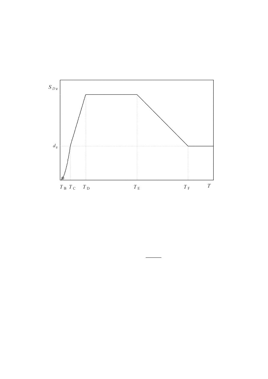
prEN 1998-1:2003 (E)
199
ANNEX A (Informative)
ELASTIC DISPLACEMENT RESPONSE SPECTRUM
A.1
For structures of long vibration period, the seismic action may be represented in
the form of a displacement response spectrum, S
De
(T), as shown in Figure A.1.
Figure A.1: Elastic displacement response spectrum.
A.2
Up to the control period T
E
, the spectral ordinates are obtained from expressions
(3.1)-(3.4) converting S
e
(T) to S
De
(T) through expression (3.7). For vibration periods
beyond T
E
, the ordinates of the elastic displacement response spectrum are obtained
from expressions (A.1) and (A.2).
−
−
−
+
⋅
⋅
⋅
=
≤
≤
)
5
,
2
1
(
5
,
2
025
,
0
)
(
:
E
F
E
D
C
g
De
F
E
η
T
T
T
T
η
T
T
S
a
T
S
T
T
T
(A.1)
g
De
F
)
(
:
d
T
S
T
T
=
≥
(A.2)
where S, T
C
, T
D
are given in Tables 3.2 and 3.3,
η is given by expression (3.6) and d
g
is
given by expression (3.12). The control periods T
E
and T
F
are presented in Table A.1.

prEN 1998-1:2003 (E)
200
Table A.1: Additional control periods for Type 1 displacement spectrum.
Ground type
T
E
(s)
T
F
(s)
A
4,5 10,0
B 5,0
10,0
C 6,0
10,0
D 6,0
10,0
E 6,0
10,0

prEN 1998-1:2003 (E)
201
ANNEX B (Informative)
DETERMINATION OF THE TARGET DISPLACEMENT FOR
NONLINEAR STATIC (PUSHOVER) ANALYSIS
B.1 General
The target displacement is determined from the elastic response spectrum (see 3.2.2.2).
The capacity curve, which represents the relation between base shear force and control
node displacement, is determined in accordance with 4.3.3.4.2.3.
The following relation between normalized lateral forces F
i
and normalized
displacements
Φ
i
is assumed:
i
i
i
Φ
m
F
=
(B.1)
where m
i
is the mass in the i-th storey.
Displacements are normalized in such a way that
Φ
n
= 1, where n is the control node
(usually, n denotes the roof level). Consequently, F
n
= m
n
.
B.2
Transformation to an equivalent Single Degree of Freedom (SDOF) system
The mass of an equivalent SDOF system m
*
is determined as:
∑
∑
=
=
i
i
i
*
F
m
m
Φ
(B.2)
and the transformation factor is given by:
∑
∑
∑
=
=
i
2
i
i
2
i
i
*
m
F
F
m
m
Φ
Γ
(B.3)
The force F
*
and displacement d
*
of the equivalent SDOF system are computed as:
Γ
b
*
F
F
=
(B.4)
Γ
n
*
d
d
=
(B.5)
where F
b
and d
n
are, respectively, the base shear force and the control node
displacement of the Multi Degree of Freedom (MDOF) system.
B.3
Determination of the idealized elasto-perfectly plastic force – displacement
relationship
The yield force F
y
*
, which represents also the ultimate strength of the idealized system,
is equal to the base shear force at the formation of the plastic mechanism. The initial
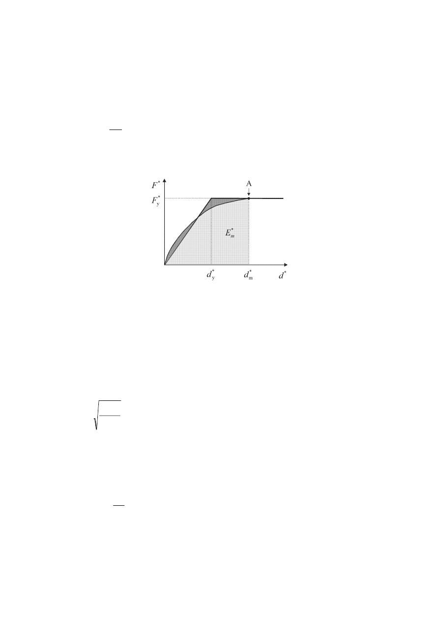
prEN 1998-1:2003 (E)
202
stiffness of the idealized system is determined in such a way that the areas under the
actual and the idealized force – deformation curves are equal (see Figure B.1).
Based on this assumption, the yield displacement of the idealised SDOF system d
y
*
is
given by:
−
=
*
y
*
m
*
m
*
y
2
F
E
d
d
(B.6)
where E
m
*
is the actual deformation energy up to the formation of the plastic
mechanism.
Key
A plastic
mechanism
Figure B.1: Determination of the idealized elasto - perfectly plastic force –
displacement relationship.
B.4
Determination of the period of the idealized equivalent SDOF system
The period T
*
of the idealized equivalent SDOF system is determined by:
*
y
*
y
*
*
2
F
d
m
T
π
=
(B.7)
B.5
Determination of the target displacement for the equivalent SDOF system
The target displacement of the structure with period T
*
and unlimited elastic behaviour
is given by:
2
*
*
e
*
et
2
)
(
=
π
T
T
S
d
(B.8)
where S
e
(T
*
) is the elastic acceleration response spectrum at the period T
*
.
For the determination of the target displacement d
t
*
for structures in the short-period
range and for structures in the medium and long-period ranges different expressions

prEN 1998-1:2003 (E)
203
should be used as indicated below. The corner period between the short- and medium-
period range is T
C
(see Figure 3.1 and Tables 3.2 and 3.3).
a)
C
*
T
T
<
(short period range)
If F
y
*
/ m
*
≥ S
e
(T
*
), the response is elastic and thus
*
et
*
t
d
d
=
(B.9)
If F
y
*
/ m
*
< S
e
(T
*
), the response is nonlinear and
(
)
*
et
*
C
u
u
*
et
*
t
1
1
d
T
T
q
q
d
d
≥
−
+
=
(B.10)
where q
u
is the ratio between the acceleration in the structure with unlimited elastic
behaviour S
e
(T
*
) and in the structure with limited strength F
y
*
/ m
*
.
*
*
*
e
u
)
(
y
F
m
T
S
q
=
(B.11)
b)
C
*
T
T
≥
(medium and long period range)
*
et
*
t
d
d
=
(B.12)
d
t
* need not exceed 3 d
et
*.
The relation between different quantities can be visualized in Figures B.2 a) and b). The
figures are plotted in acceleration - displacement format. Period T
*
is represented by the
radial line from the origin of the coordinate system to the point at the elastic response
spectrum defined by coordinates d
*
= S
e
(T
*
)(T
*
/2
π)
2
and S
e
(T
*
).
Iterative procedure (optional)
If the target displacement d
t
*
determined in the 4
th
step is much different from the
displacement d
m
*
(Figure B.1) used for the determination of the idealized elasto-
perfectly plastic force – displacement relationship in the 2
nd
step, an iterative procedure
may be applied, in which steps 2 to 4 are repeated by using in the 2
nd
step d
t
*
(and the
corresponding F
y
*
) instead of d
m
*
.
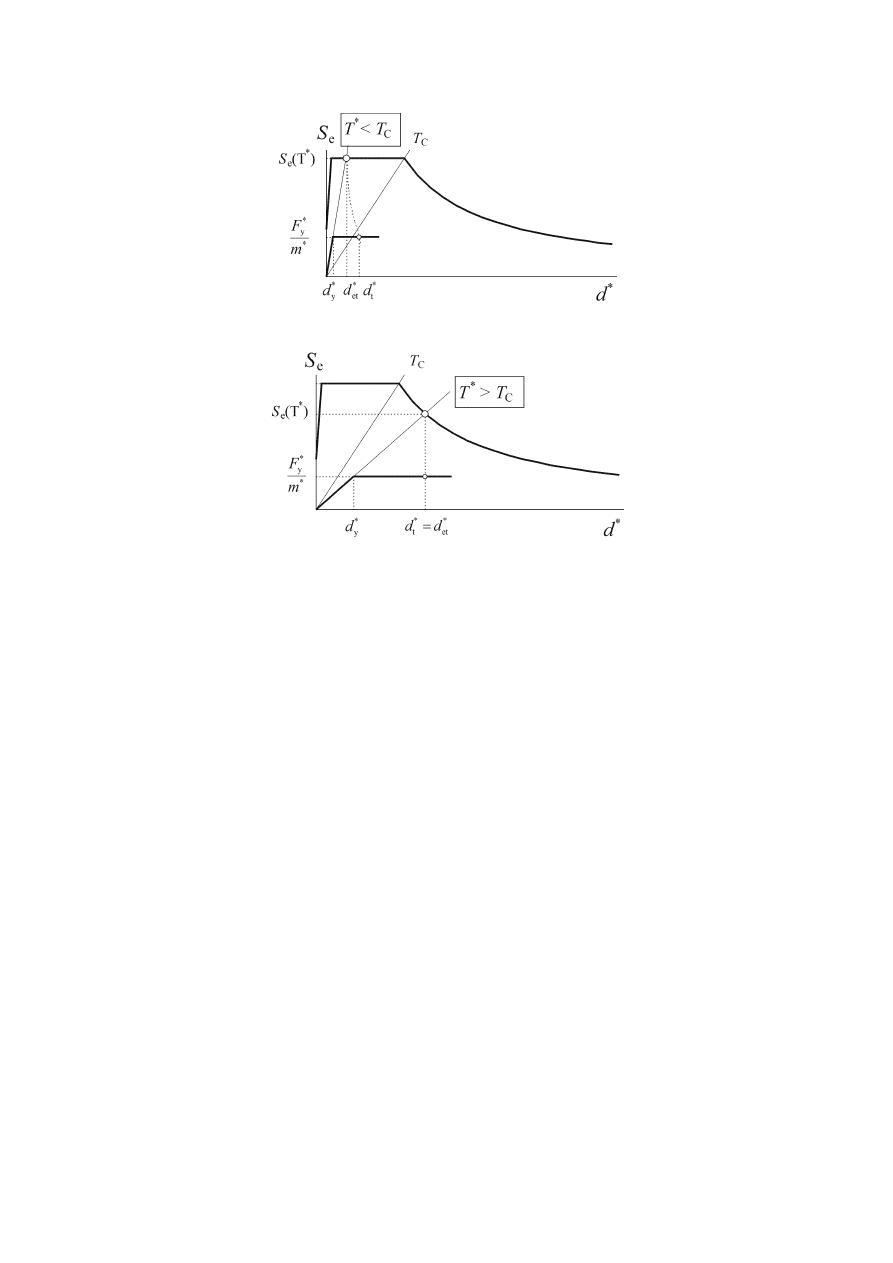
prEN 1998-1:2003 (E)
204
a) Short period range
b) Medium and long period range
Figure B.2: Determination of the target displacement for the equivalent SDOF
system
B.6
Determination of the target displacement for the MDOF system
The target displacement of the MDOF system is given by:
*
t
t
d
d
Γ
=
(B.13)
The target displacement corresponds to the control node.

prEN 1998-1:2003 (E)
205
ANNEX C (Normative)
DESIGN OF THE SLAB OF STEEL-CONCRETE COMPOSITE
BEAMS AT BEAM-COLUMN JOINTS IN MOMENT RESISTING
FRAMES
C.1 General
(1)
This annex refers to the design of the slab and of its connection to the steel
frame in moment resisting frames in which beams are composite T-beams comprising a
steel section with a slab.
(2)
The annex has been developed and validated experimentally in the context of
composite moment frames with rigid connections and plastic hinges forming in the
beams. The expressions in this annex have not been validated for cases with partial
strength connections in which deformations are more localised in the joints.
(3)
Plastic hinges at beam ends in a composite moment frame shall be ductile.
According to this annex two requirements shall be fulfilled to ensure that a high
ductility in bending is obtained:
− early buckling of the steel part shall be avoided;
− early crushing of the concrete of the slab shall be avoided.
(4)
The first condition imposes an upper limit on the cross-sectional area A
s
of the
longitudinal reinforcement in the effective width of the slab. The second condition
imposes a lower limit on the cross-sectional area A
T
of the transverse reinforcement in
front of the column.
C.2
Rules for prevention of premature buckling of the steel section
(1) Paragraph
7.6.1(4) applies.
C.3
Rules for prevention of premature crushing of concrete
C.3.1 Exterior column - Bending of the column in direction perpendicular to
façade; applied beam bending moment negative: M < 0
C.3.1.1 No façade steel beam; no concrete cantilever edge strip (Figure C.1(b)).
(1)
When there is no façade steel beam and no concrete cantilever edge strip, the
moment capacity of the joint should be taken as the plastic moment resistance of the
steel beam alone.
C.3.1.2 No façade steel beam; concrete cantilever edge strip present (Figure C.1(c)).
(1)
When there is a concrete cantilever edge strip but no façade steel beam, EN
1994-1-1:2004 applies for the calculation of the moment capacity of the joint.
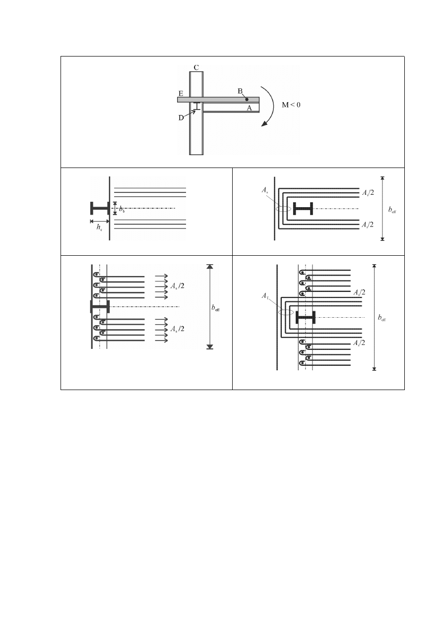
prEN 1998-1:2003 (E)
206
(a)
(b)
(c)
(d)
(e)
Key:
(a) elevation
(b) no concrete cantilever edge strip – no façade steel beam – see C.3.1.1.
(c) concrete cantilever edge strip – no façade steel beam – see C.3.1.2.
(d) no concrete cantilever edge strip – façade steel beam – see C.3.1.3.
(e) concrete cantilever edge strip – façade steel beam – see C.3.1.4.
A main
beam;
B slab;
C
exterior column;
D
façade steel beam;
E
concrete cantilever edge strip
Figure C.1: Configurations of exterior composite beam-to-column joints under
negative bending moment in a direction perpendicular to façade

prEN 1998-1:2003 (E)
207
C.3.1.3 Façade steel beam present; slab extending up to column outside face; no
concrete cantilever edge strip (Figure C.1(d)).
(1)
When there is a façade steel beam but no concrete cantilever edge strip, the
moment capacity of the joint may include the contribution of the slab reinforcements
provided that the requirements in (2) to (7) of this subclause are satisfied.
(2)
Reinforcing bars of the slab should be effectively anchored to the shear
connectors of the façade steel beam.
(3)
The façade steel beam should be fixed to the column.
(4)P The
cross-sectional
area of reinforcing steel A
s
shall be such that yielding of the
reinforcing steel takes place before failure of the connectors and of the façade beams.
(5)P The cross-sectional area of reinforcing steel A
s
and the connectors shall be
placed over a width equal to the effective width defined in 7.6.3 and Table 7.5 II.
(6)
The connectors should be such that:
n
⋅ P
Rd
≥ 1,1 F
Rds
(C.1)
where
n
is the number of connectors in the effective width;
P
Rd
is the design resistance of one connector;
F
Rds
is the design resistance of the re-bars present in the effective width: F
Rds
= A
s
⋅f
yd
f
yd
is
the
design yield strength of the slab reinforcement.
(7)
The façade steel beam should be verified in bending, shear and torsion under the
horizontal force F
Rds
applied at the connectors.
C.3.1.4 Façade steel beam and concrete cantilever edge strip present (Figure
C.1(e)).
(1)
When there is both a façade steel beam and a concrete cantilever edge strip, the
moment capacity of the joint may include the contribution of: (a) the force transferred
through the façade steel beam as described in C.3.1.3 (see (2) of this subclause) and (b)
the force transferred through the mechanism described in EN 1994-1-1:2004 (see (3) of
this subclause).
(2)
The part of the capacity which is due to the cross-sectional area of reinforcing
bars anchored to the transverse façade steel beam, may be calculated in accordance with
C.3.1.3, provided that the requirements in (2) to (7) of C.3.1.3 are satisfied.
(3)
The part of the capacity which is due to the cross-sectional area of reinforcing
bars anchored within the concrete cantilever edge strip may be calculated in accordance
with C.3.1.2.

prEN 1998-1:2003 (E)
208
C.3.2 Exterior column - Bending of the column in direction perpendicular to
façade; applied beam bending moment positive: M > 0
C.3.2.1 No façade steel beam; slab extending up to the column inside face (Figure
C.2(b-c)).
(1)
When the concrete slab is limited to the interior face of the column, the moment
capacity of the joint may be calculated on the basis of the transfer of forces by direct
compression (bearing) of the concrete on the column flange. This capacity may be
calculated from the compressive force computed in accordance with (2) of this
subclause, provided that the confining reinforcement in the slab satisfies (4) of this
subclause.
(2)
The maximum value of the force transmitted to the slab may be taken as:
F
Rd1
= b
b
d
eff
f
cd
(C.2)
where
d
eff
is the overall depth of the slab in case of solid slabs or the thickness of the slab
above the ribs of the profiled sheeting for composite slabs;
b
b
is the bearing width of the concrete of the slab on the column (see Figure 7.7).
(3)
Confinement of the concrete next to the column flange is necessary. The cross-
sectional area of confining reinforcement should satisfy the following expression:
T
yd,
cd
b
b
eff
T
15
,
0
15
,
0
25
,
0
f
f
l
b
l
b
d
A
−
≥
(C.3)
where
f
yd,T
is
the
design yield strength of the transverse reinforcement in the slab.
The cross-sectional area A
T
of this reinforcement should be uniformly distributed over a
length of the beam equal to b
b
. The distance of the first reinforcing bar to the column
flange should not exceed 30 mm.
(4)
The cross-sectional area A
T
of steel defined in (3) may be partly or totally
provided by reinforcing bars placed for other purposes, for instance for the bending
resistance of the slab.

prEN 1998-1:2003 (E)
209
(a)
Key:
(a) elevation;
A main
beam;
B slab;
C
exterior column;
D
façade steel beam;
E
concrete cantilever edge strip
Figure C.2: Configurations of exterior composite beam-to-column joints under
positive bending moments in a direction perpendicular to façade and possible
transfer of slab forces
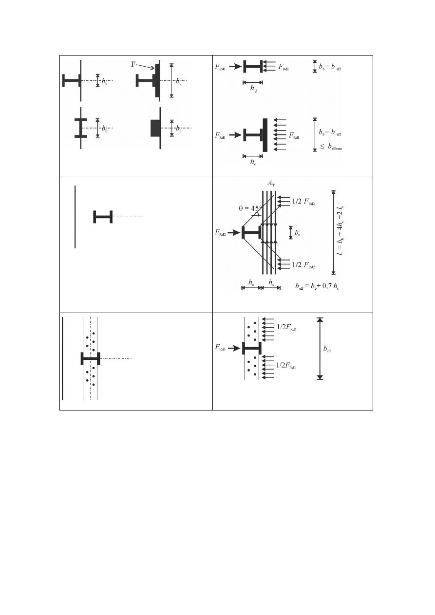
prEN 1998-1:2003 (E)
210
(b)
(c)
(d)
(e)
(f)
(g)
Key:
(b) no concrete cantilever edge strip – no façade steel beam – see C.3.2.1;
(c) mechanism 1;
(d) slab extending up to the column outside face or beyond as a concrete cantilever edge
strip – no façade steel beam – see C.3.2.2;
(e) mechanism 2;
(f) slab extending up to the column outside face or beyond as a concrete cantilever edge
strip – façade steel beam present – see C.3.2.3;
(g) mechanism 3.
F
additional device fixed to the column for bearing.
Figure C.2 (continuation): Configurations of exterior composite beam-to-column
joints under positive bending moment in direction perpendicular to façade and
possible transfer of slab forces.

prEN 1998-1:2003 (E)
211
C.3.2.2 No façade steel beam; slab extending up to column outside face or beyond
as a concrete cantilever edge strip (Figure C.2(c-d-e))
(1)
When no façade steel beam is present, the moment capacity of the joint may be
calculated from the compressive force developed by the combination of the following
two mechanisms:
mechanism 1: direct compression on the column. The design value of the force that is
transferred by means of this mechanism should not exceed the value given by the
following expression
F
Rd1
= b
b
d
eff
f
cd
(C.4)
mechanism 2: compressed concrete struts inclined to the column sides. If the angle of
inclination is equal to 45°, the design value of the force that is transferred by means of
this mechanism should not exceed the value given by the following expression:
F
Rd2
= 0,7h
c
d
eff
f
cd
(C.5)
where
h
c
is the depth of the column steel section.
(2)
The tension-tie total steel cross-sectional area A
T
should satisfy the following
expression (see Figure C.2.(e)):
T
yd,
Rd2
T
f
F
A
≥
(C.6)
(3)
The steel area A
T
should be distributed over a length of beam equal to h
c
and be
fully anchored. The required length of reinforcing bars is L = b
b
+ 4 h
c
+ 2 l
b
, where l
b
is
the anchorage length of these bars in accordance with EN 1992-1-1:2004.
(4)
The moment capacity of the joint may be calculated from the design value of the
maximum compression force that can be transmitted:
F
Rd1
+ F
Rd2
= b
eff
d
eff
f
cd
(C.7)
b
eff
is the effective width of the slab at the joint as deduced from 7.6.3 and in Table
7.5II. In this case b
eff
= 0,7 h
c
+ b
b
.
C.3.2.3 Façade steel beam present; slab extending up to column outside face or
beyond as a concrete cantilever edge strip (Figure C.2(c-e-f-g)).
(1)
When a façade steel beam is present, a third mechanism of force transfer F
Rd3
is
activated in compression involving the façade steel beam.
F
Rd3
= n
⋅ P
Rd
(C.8)
where

prEN 1998-1:2003 (E)
212
n
is the number of connectors within the effective width computed from 7.6.3 and
Table 7.5II;
P
Rd
is the design resistance of one connector.
(2)
C.3.2.2 applies
(3)
The design value of the maximum compression force that can be transmitted is
b
eff
d
eff
f
cd
. It is transmitted if the following expression is satisfied:
F
Rd1
+ F
Rd2
+ F
Rd3
> b
eff
d
eff
f
cd
. (C.9)
The "full" composite plastic moment resistance is achieved by choosing the number n of
connectors so as to achieve an adequate force F
Rd3
. The maximum effective width
corresponds to b
eff
defined in 7.6.3 and Table 7.5 II. In this case, b
eff
= 0,15 l.
C.3.3 Interior column
C.3.3.1 No transverse beam present (Figure C.3(b-c)).
(1)
When no transverse beam is present, the moment capacity of the joint may be
calculated from the compressive force developed by the combination of the following
two mechanisms:
mechanism 1: direct compression on the column. The design value of the force that is
transferred by means of this mechanism should not exceed the value given by the
following expression:
F
Rd1
= b
b
d
eff
f
cd
. (C.10)
mechanism 2: compressed concrete struts inclined at 45° to the column sides. The
design value of the force that is transferred by means of this mechanism should not
exceed the value given by the following expression:
F
Rd2
= 0,7 h
c
d
eff
f
cd
. (C.11)
(2)
The tension-tie cross-sectional area A
T
required for the development of
mechanism 2 should satisfy the following expression:
T
yd,
Rd2
T
f
F
A
≥
(C.12)
(3)
The same cross-sectional area A
T
should be placed on each side of the column to
provide for the reversal of bending moments.
(4)
The design value of the compressive force developed by the combination of the
two mechanisms is
F
Rd1
+ F
Rd2
= (0,7 h
c
+ b
b
) d
eff
f
cd
(C.13)
(5)
The total action effect which is developed in the slab due to the bending
moments on opposite sides of the column and needs to be transferred to the column

prEN 1998-1:2003 (E)
213
through the combination of mechanisms 1 and 2 is the sum of the tension force F
st
in the
reinforcing bars parallel to the beam at the side of the column where the moment is
negative and of the compression force F
sc
in the concrete at the side of the column
where the moment is positive:
F
st
+ F
sc
= A
s
f
yd
+ b
eff
d
eff
f
cd
(C.14)
where
A
s
is the cross-sectional area of bars within the effective width in negative bending
b
eff
specified in 7.6.3 and Table 7.5 II; and
b
eff
is the effective width in positive bending as specified in 7.6.3 and Table 7.5 II.
In this case, b
eff
= 0,15 l.
(6)
For the design to achieve yielding in the bottom flange of the steel section
without crushing of the slab concrete, the following condition should be fulfilled
1,2 (F
sc
+ F
st
)
≤ F
Rd1
+ F
Rd2
(C.15)
If the above condition is not fulfilled, the capability of the joint to transfer forces from
the slab to the column should be increased, either by the presence of a transverse beam
(see C.3.3.2), or by increasing the direct compression of the concrete on the column by
additional devices (see C.3.2.1).
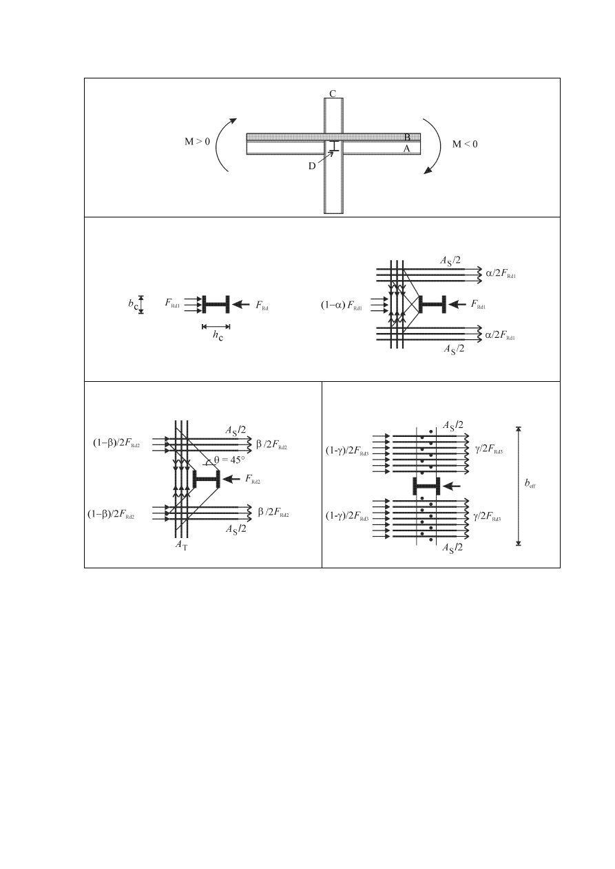
prEN 1998-1:2003 (E)
214
(a)
(b)
(c)
(d)
Key:
(a) elevation;
(b) mechanism 1;
(c) mechanism 2;
(d) mechanism 3
A main
beam;
B slab;
C interior
column;
D transverse
beam
Figure C.3. Possible transfer of slab forces in an interior composite beam-to-
column joint with and without a transverse beam, under a positive bending
moment on one side and a negative bending moment on the other side.

prEN 1998-1:2003 (E)
215
C.3.3.2 Transverse beam present (Figure C.3(d)).
(1)
When a transverse beam is present, a third mechanism of force transfer F
Rd3
is
activated involving the transverse steel beam.
F
Rd3
= n
⋅ P
Rd
(C.16)
where
n
is the number of connectors in the effective width computed using 7.6.3 and
Table 7.5 II.
P
Rd
is the design resistance of one connector
(2)
C.3.3.1(2) applies for the tension-tie.
(3)
The design value of the compressive force developed by the combination of the
three mechanisms is:
F
Rd1
+ F
Rd2
+ F
Rd3
= (0,7 h
c
+ b
b
) d
eff
f
cd
+ n
⋅P
Rd
(C.17)
where n is the number of connectors in b
eff
for negative moment or for positive moment
as defined in 7.6.3 and Table 7.5 II, whichever is greater out of the two beams framing
into the column.
(4)
C.3.3.1(5) applies for the calculation of the total action effect, F
st
+ F
sc
,
developed in the slab due to the bending moments on opposite sides of the column.
(5)
For the design to achieve yielding in the bottom flange of the steel section
without crushing of the concrete in the slab, the following condition should be fulfilled
1,2 (F
sc
+ F
st
)
≤ F
Rd1
+ F
Rd2
+ F
Rd3
(C.18)
Wyszukiwarka
Podobne podstrony:
Eurocode 8 Part 1 prEN 1998 1 (12 2003)
Eurocode 8 Part 5 prEn 1998 5 (12 2003)
Eurocode 8 Part 1 prEN 1998 1 (12 2003)
Eurocode 8 Part 3 prEN 1998 3 (07 2003)
Eurocode 8 Part 4 prEN 1998 4 2003 (12 2003)
Eurocode 1 Part 1,3 prEN 1991 1 3 2003
Eurocode 1 Part 1,5 prEN 1991 1 5 2003
Eurocode 1 Part 1,7 prEN 1991 1 7 2003
Eurocode 3 Part 1,9 PrEN 1993 1 9 2003
Eurocode 3 Part 1,8 prEN 1993 1 8 2003
Eurocode 3 Part 1,9 PrEN 1993 1 9 2003
Eurocode 3 Part 1,8 prEN 1993 1 8 2003
Eurocode 1 Part 1,6 prEN 1991 1 6 2004
Eurocode 1 Part 2 prEN 1991 2 2002
Eurocode 1 Part 1,2 prEN 1991 1 2 2002
Eurocode 1 Part 1,1 prEN 1991 1 1 2001
więcej podobnych podstron