LPG FUEL SYSTEM
AISAN CLOSED-LOOP
S/H1.50-2.00XMS
(S/H25-40XMS) [D010, E001];
S/H2.00-3.20XM
(S/H40-65XM) [D187, H177]
PART NO. 1495954
900 SRM 948

SAFETY PRECAUTIONS
MAINTENANCE AND REPAIR
• When lifting parts or assemblies, make sure all slings, chains, or cables are correctly
fastened, and that the load being lifted is balanced. Make sure the crane, cables, and
chains have the capacity to support the weight of the load.
• Do not lift heavy parts by hand, use a lifting mechanism.
• Wear safety glasses.
• DISCONNECT THE BATTERY CONNECTOR before doing any maintenance or repair
on electric lift trucks. Disconnect the battery ground cable on internal combustion lift
trucks.
• Always use correct blocks to prevent the unit from rolling or falling. See HOW TO PUT
THE LIFT TRUCK ON BLOCKS in the Operating Manual or the Periodic Mainte-
nance section.
• Keep the unit clean and the working area clean and orderly.
• Use the correct tools for the job.
• Keep the tools clean and in good condition.
• Always use HYSTER APPROVED parts when making repairs. Replacement parts
must meet or exceed the specifications of the original equipment manufacturer.
• Make sure all nuts, bolts, snap rings, and other fastening devices are removed before
using force to remove parts.
• Always fasten a DO NOT OPERATE tag to the controls of the unit when making repairs,
or if the unit needs repairs.
• Be sure to follow the WARNING and CAUTION notes in the instructions.
• Gasoline, Liquid Petroleum Gas (LPG), Compressed Natural Gas (CNG), and Diesel fuel
are flammable. Be sure to follow the necessary safety precautions when handling these
fuels and when working on these fuel systems.
• Batteries generate flammable gas when they are being charged. Keep fire and sparks
away from the area. Make sure the area is well ventilated.
NOTE: The following symbols and words indicate safety information in this
manual:
WARNING
Indicates a condition that can cause immediate death or injury!
CAUTION
Indicates a condition that can cause property damage!

LPG Fuel System
Table of Contents
TABLE OF CONTENTS
General ...............................................................................................................................................................
Description and Operation ................................................................................................................................
Fuel Tank .......................................................................................................................................................
Oxygen Sensor ...............................................................................................................................................
Regulator........................................................................................................................................................
Start Mode .................................................................................................................................................
Idle Mode ...................................................................................................................................................
Run Mode...................................................................................................................................................
Resonator .......................................................................................................................................................
Carburetor......................................................................................................................................................
Start Mode .................................................................................................................................................
Idle Mode ...................................................................................................................................................
Run Mode...................................................................................................................................................
Governor ....................................................................................................................................................
Hoses Replacement ............................................................................................................................................
LPG Tank Repair ...............................................................................................................................................
Remove ...........................................................................................................................................................
Install .............................................................................................................................................................
Relief Valve Repair.............................................................................................................................................
Remove and Install........................................................................................................................................
Carburetor Repair..............................................................................................................................................
Remove ...........................................................................................................................................................
Disassemble ...................................................................................................................................................
Clean ..............................................................................................................................................................
Assemble ........................................................................................................................................................
Install .............................................................................................................................................................
Fuel Injector Repair ...........................................................................................................................................
Remove ...........................................................................................................................................................
Clean and Inspect ..........................................................................................................................................
Install .............................................................................................................................................................
Governor Repair.................................................................................................................................................
Remove ...........................................................................................................................................................
Inspect ............................................................................................................................................................
Install .............................................................................................................................................................
Regulator Repair ................................................................................................................................................
Remove ...........................................................................................................................................................
Install .............................................................................................................................................................
Oxygen Sensor Repair .......................................................................................................................................
Remove and Install........................................................................................................................................
Vacuum Switches Repair ...................................................................................................................................
Remove and Install........................................................................................................................................
Inspect ............................................................................................................................................................
Resistor Repair...................................................................................................................................................
Remove and Install........................................................................................................................................
Inspect ............................................................................................................................................................
Carburetor and New Regulator Adjustment ....................................................................................................
Idle Speed and Fuel Mixture ........................................................................................................................
Idle Control Adjustment................................................................................................................................
Governor Checks and Adjustments ..................................................................................................................
Checks ............................................................................................................................................................
Adjustments ...................................................................................................................................................
©2005 HYSTER COMPANY
i

Table of Contents
LPG Fuel System
TABLE OF CONTENTS (Continued)
Throttle Linkage Adjustment............................................................................................................................
MONOTROL Pedal Check.................................................................................................................................
Check Engine Light ...........................................................................................................................................
Inspect Warning Lamp ..................................................................................................................................
Check Feedback Operation ...........................................................................................................................
Check VAC1 and VAC2 Signals ....................................................................................................................
Check Resistor ...............................................................................................................................................
Check Fuel Injector .......................................................................................................................................
Check Oxygen Sensor ....................................................................................................................................
Check Vacuum Switch 1 ................................................................................................................................
Check Vacuum Switch 2 ................................................................................................................................
After Completing Checks ..............................................................................................................................
Troubleshooting..................................................................................................................................................
This section is for the following models:
S/H1.50-2.00XMS (S/H25-40XMS) [D010, E001];
S/H2.00-3.20XM (S/H40-65XM) [D187, H177]
ii

900 SRM 948
Description and Operation
General
This section has the description, operation, and repair procedures for the parts of the LPG fuel system used on
the Mazda 2.0 liter, Mazda 2.2 liter, and GM 3.0L Engines.
Description and Operation
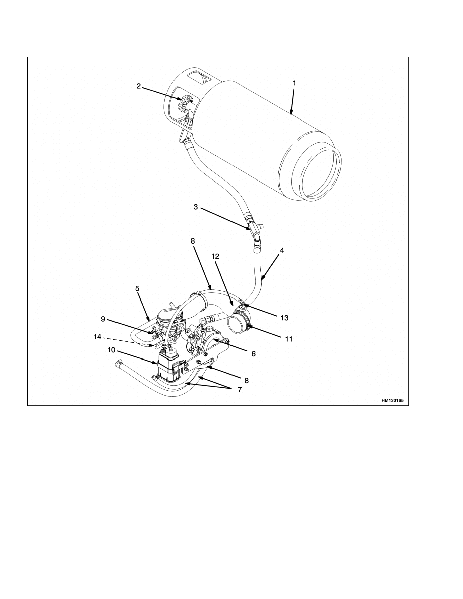
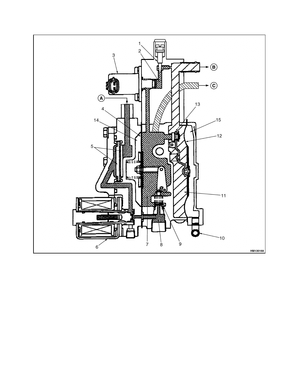
The LPG fuel system has a fuel tank and valve, hy-
drostatic relief valve, regulator, carburetor, solenoid
valve, makeup fuel injector, fuel pressure sensor and
indicator lamp, and governor. The LPG arrangement
is shown in Figure 1 and Figure 2.
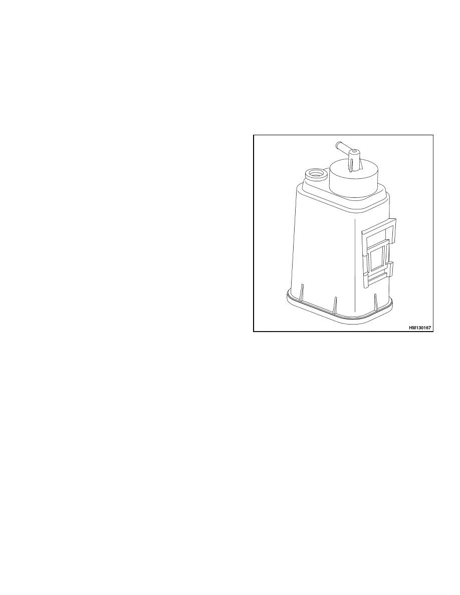
FUEL TANK
NOTE: Some LPG tanks have an auxiliary fill fitting
instead of a plug.
The fuel tank is the reservoir for the LPG system.
See Figure 3. The fuel tank keeps the fuel in the
liquid condition. The pressure of the fuel is 900 to
1100 kPa (130 to 160 psi) with 100% propane when
the tank is full and at an ambient temperature of
27 C (81 F). The tank has a pressure relief valve that
is set at 3310 kPa (480 psi). The inlet tube for the
pressure relief valve is in the vapor area at the top of
the tank.
OXYGEN SENSOR
The closed-loop system incorporates an oxygen sen-
sor in the exhaust pipe. The sensor constantly makes
comparisons between the oxygen content inside the
exhaust manifold and the air outside the engine. If a
rich or lean air/fuel mixture is sensed in the exhaust,
the sensor provides a signal to the engine control unit
(ECU). The ECU will then make an adjustment to the
mixture ratio by turning the makeup fuel injector on
or off.
The basic operations of the regulator and the carbu-
retor are similar to the Aisan open-loop LPG system.
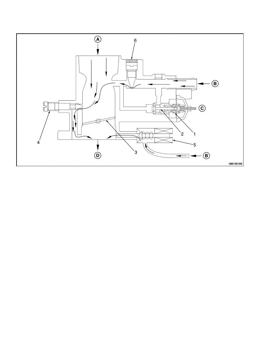
REGULATOR
The function of the regulator is to change the liquid
fuel to a vapor (gas) and to control the pressure of
the vapor. See Figure 4,Figure 5 and Figure 6. The
LPG fuel changes from a liquid to a vapor inside the
primary pressure-reduction chamber. This conver-
sion process cools the vapor, which in turn cools the
surrounding parts of the regulator. Engine coolant
is circulated through the regulator and, by convec-
tion, transfers the cold out of the chamber. Regard-
less of the ambient temperature, the engine coolant
is always warmer than the vapor after expansion,
thereby providing the warming function. This warm-
ing function of the engine coolant prevents the regu-
lator from being too cold to operate.
The regulator consists of four chambers:
Chamber A - Start of the vaporization process.
Chamber B - Primary pressure-reduction cham-
ber where primary vaporization occurs and the
pressure is reduced. Also provides low-pressure
vapor for the fuel injector.
Chamber C - Secondary pressure-reduction
chamber where the vapor pressure is reduced to
zero (atmospheric).
Chamber D - Provides fuel during engine start
and idle.
The regulator has three operating modes:
start
mode, idle mode, and run mode. These modes are
described in detail in the following sections.
1
Description and Operation
900 SRM 948
1.
LPG TANK
2.
SHUTOFF VALVE
3.
RELIEF VALVE
4.
LIQUID LPG HOSE
5.
LPG VAPOR HOSE
6.
REGULATOR/FILTER
7.
COOLING SYSTEM HOSES
8.
VACUUM/BALANCE LINE
9.
LPG CARBURETOR
10. RESONATOR
11. AIR FILTER DISCHARGE ELBOW
12. AIR INTAKE HOSE
13. ORIFICE FITTING
14. FUEL INJECTOR
Figure 1. Aisan Closed-Loop LPG System
2
900 SRM 948
Description and Operation
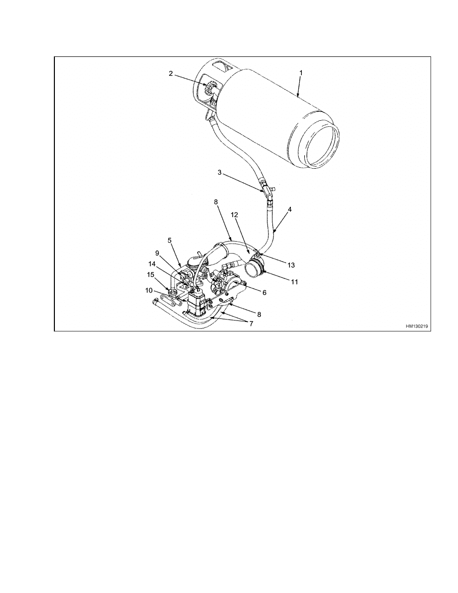
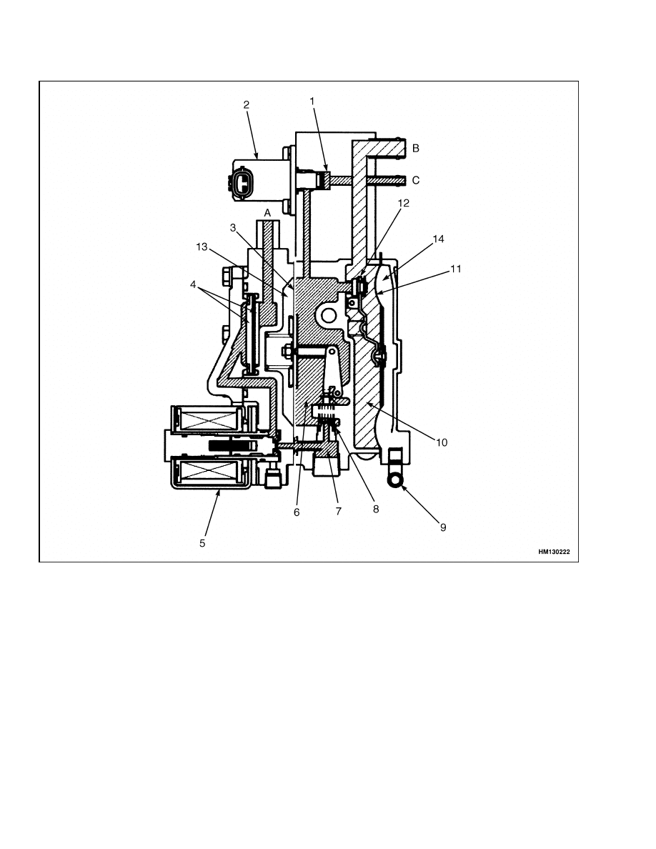
1.
LPG TANK
2.
SHUTOFF VALVE
3.
RELIEF VALVE
4.
LIQUID LPG HOSE
5.
LPG VAPOR HOSE
6.
REGULATOR/FILTER
7.
COOLING SYSTEM HOSES
8.
VACUUM/BALANCE LINE
9.
LPG CARBURETOR
10. RESONATOR
11. AIR FILTER DISCHARGE ELBOW
12. AIR INTAKE HOSE
13. ORIFICE FITTING
14. FUEL INJECTOR
15. FUEL FILTER (SLOW)
Figure 2. Aisan Closed Loop LPG System, EPA Compliant Engine
3
Description and Operation
900 SRM 948
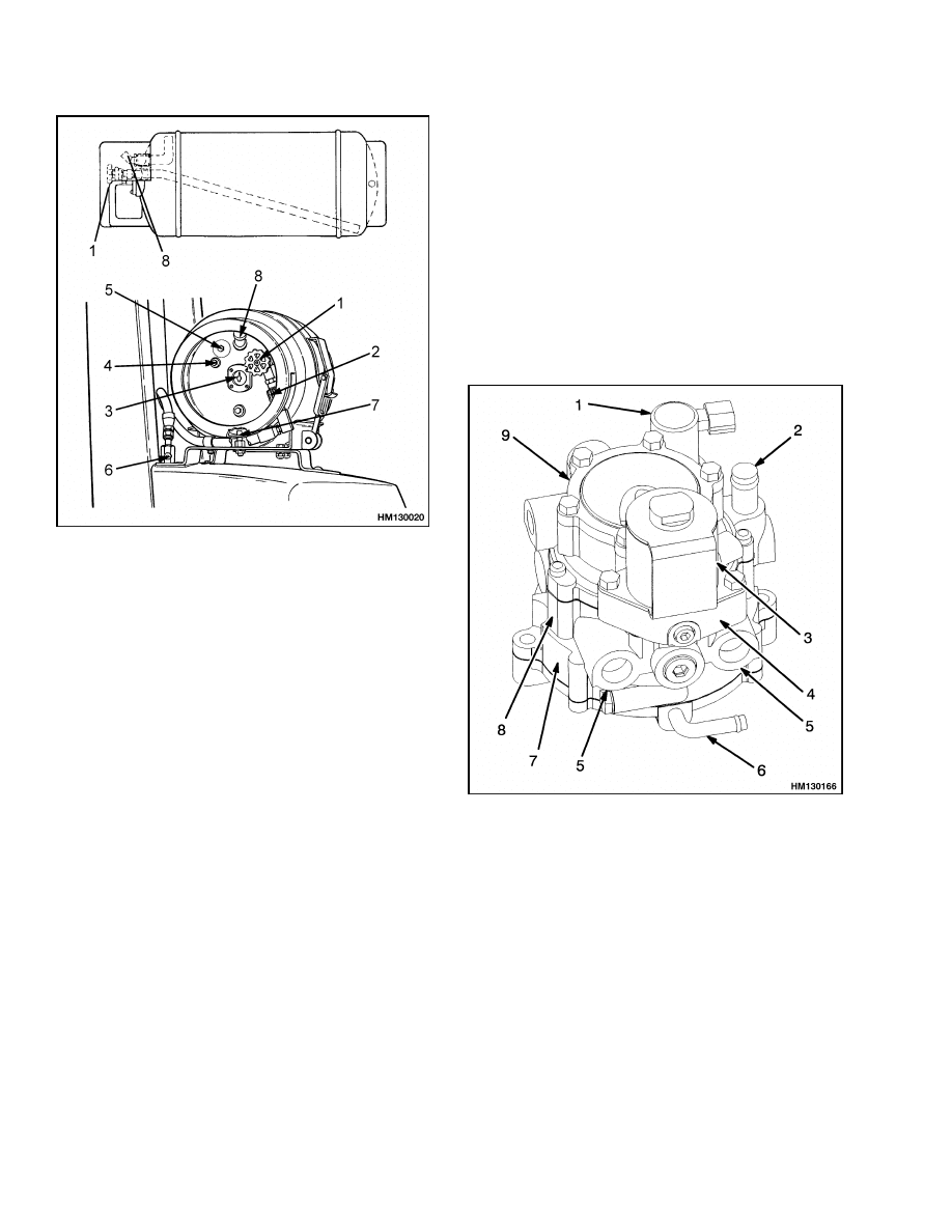
1.
SHUTOFF VALVE
2.
QUICK-DISCONNECT FITTING
3.
FUEL GAUGE
4.
PLUG
5.
LIQUID LEVEL INDICATOR
6.
RELIEF VALVE
7.
ALIGNMENT PIN
8.
TANK RELIEF VALVE
Figure 3. LPG Tank
Start Mode
When the ignition switch is turned to the START po-
sition and the engine begins to crank, both the main
solenoid valve and the idle bypass solenoid valve are
activated, allowing the LPG to flow from the fuel
tank through the fuel filter to chamber A. See Fig-
ure 5 and Figure 6. The fuel pressure opens the inlet
valve between chambers A and B, and the fuel en-
ters the primary pressure reduction chamber (cham-
ber B).
When the pressure in chamber B reaches 24.5 to
34.5 kPa (7.2 to 10.2 inHg), the diaphragm expands
outward and closes the inlet valve, maintaining a
constant pressure in chamber B. A very small por-
tion of the fuel is bled off into chamber D, where the
idle mixture adjusting screw controls the amount of
fuel that is allowed to flow out to the carburetor to
start ignition.
When the throttle valve is opened slightly, the de-
mand for fuel at the carburetor causes a slight vac-
uum at the output port of the regulator. This vacuum
causes the diaphragm in chamber C to depress. This
opens the inlet valve between chambers B and C, al-
lowing fuel to flow from chamber B to chamber C.
This allows large amounts of fuel to flow to the car-
buretor for complete combustion.
1.
IDLE BYPASS SOLENOID VALVE
FUEL OUTLET
3.
MAIN SOLENOID VALVE
4.
CHAMBER A
5.
COOLANT PORTS
6.
RESONATOR PORT
7.
CHAMBER C
8.
CHAMBER B
9.
FUEL FILTER CHAMBER
Figure 4. Regulator
4
900 SRM 948
Description and Operation
A. LPG INPUT FROM FUEL TANK
B. LPG OUTPUT TO CARBURETOR
C. LPG OUTPUT TO FUEL INJECTOR
1.
IDLE MIXTURE ADJUSTING SCREW*
2.
CHAMBER D
3.
IDLE BYPASS SOLENOID
4.
DIAPHRAGM*
5.
FUEL FILTER
6.
MAIN SOLENOID
7.
CHAMBER B
8.
CHAMBER A
9.
INLET VALVE*
10. RESONATOR PORT
11. CHAMBER C
12. DIAPHRAGM*
13. INLET VALVE*
14. VACUUM CHAMBER 1
15. VACUUM CHAMBER 2
*THE IDLE MIXTURE ADJUSTING SCREW ON THIS REGULATOR CANNOT BE ADJUSTED. ITEMS 4, 9, 12,
AND 13 ARE NOT SERVICEABLE PARTS.
Figure 5. Inside the Regulator
5
Description and Operation
900 SRM 948
A. LPG INPUT FROM FUEL TANK
B. LPG OUTPUT TO CARBURETOR
C. LPG OUTPUT TO FUEL FILTER
1.
CHAMBER D
2.
IDLE BY-PASS SOLENOID
3.
DIAPHRAGM
4.
FUEL FILTER
5.
MAIN SOLENOID
6.
CHAMBER B
7.
CHAMBER A
8.
1ST VALVE
9.
RESONATOR CONNECTION
10. CHAMBER C
11. DIAPHRAGM
12. 2ND VALVE
13. CHAMBER 1
14. CHAMBER 2
Figure 6. Inside the Regulator (EPA Compliant Engine)
6
900 SRM 948
Description and Operation
Idle Mode
In the idle mode, the demand for fuel at the carbure-
tor is low and the vacuum is absent at the fuel outlet
port. This causes the diaphragm in chamber C to re-
lax and close the inlet valve between chambers B and
C. See Figure 5 and Figure 6. Pressure in chamber B
builds up to 24.5 to 34.5 kPa (7.2 to 10.2 inHg), caus-
ing the diaphragm in chamber B to expand and close
off the fuel supply. A balance is reached between the
amount of vaporizing (liquid) through chamber A and
the amount of vapor escaping past the idle mixture
adjusting screw in chamber D.
The idle mixture adjusting screw is set for a lean mix-
ture at the factory. The fuel injector supplies addi-
tional fuel to the carburetor at idle. The ECU con-
trols the fuel injector by using inputs from the oxy-
gen sensor and vacuum switch 1.
Run Mode
In the run mode, the throttle valve on the carbure-
tor is opened, creating a vacuum at the fuel outlet
port. This causes the diaphragm in chamber C to ex-
pand and open the inlet valve between chambers B
and C. See Figure 5 and Figure 6. This causes the
pressure to drop in chamber B and relaxes the di-
aphragm in chamber B. This opens the inlet valve
between chambers A and B. Fuel is supplied to the
carburetor through chamber C, the idle bypass valve,
and chamber D.
RESONATOR
The resonator is connected by vacuum hoses to a spe-
cial orifice fitting on the air filter discharge elbow
(see Figure 1 and Figure 7) and to the resonator port
of the regulator (see Figure 4). The resonator port
connects to vacuum chamber 2 (see Figure 5 and Fig-
ure 6).
As the air filter clogs, the intake vacuum increases
for any relative throttle position. This increased vac-
uum has a similar increase in the vacuum of cham-
bers C and 2. By increasing the vacuum of chambers
C and 2 by the same level as the intake restriction,
a balance is maintained and the relative position of
the diaphragms remains unchanged. This maintains
a constant fuel mixture regardless of the air filter re-
striction. See Figure 5 and Figure 6.
The special orifice fitting and the resonator act as
vacuum dampeners. The air being drawn through
the intake system does not flow in a constant stream,
but rather in small pulses generated during the in-
take stroke of the pistons. Without the resonator
and orifice, these pulses could be generated at a fre-
quency that is a natural harmonic of the diaphragm.
This would cause the diaphragm to vibrate uncon-
trollably and force the engine mixture to be either
very rich or lean under certain operating conditions.
Figure 7. Resonator
CARBURETOR
Like the regulator, the carburetor has three operat-
ing modes: start mode, idle mode, and run mode.
These modes are described in detail in the following
sections.
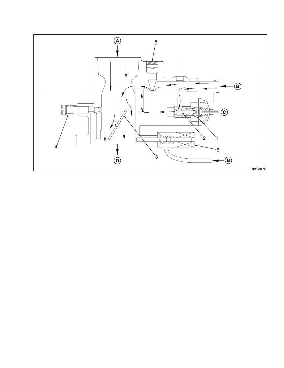
Start Mode
Before any fuel is provided to the carburetor, the ig-
nition switch must be turned to the ON position and
the engine must be cranked without pressing the ac-
celerator. See Figure 8. The ECU level control unit
on the engine wiring harness senses that the engine
is in start mode and provides an electrical signal to
energize the main solenoid, the idle bypass solenoid,
and the fuel injector. Fuel then flows from the regu-
lator to the carburetor.
7
Description and Operation
900 SRM 948
A. AIR
B. LPG
C. VACUUM FROM MANIFOLD
D. TO INTAKE MANIFOLD
1.
POWER DIAPHRAGM
2.
POWER VALVE
3.
THROTTLE VALVE
4.
IDLE AIR BYPASS ADJUSTING SCREW
5.
FUEL INJECTOR
6.
TAMPER-PROOF PLUG
Figure 8. Carburetor, Start Mode
The fuel flows past the orifice and into the main
chamber of the carburetor, where it mixes with the
air coming from the air cleaner. Because the throttle
valve is closed, the air/fuel mixture flows past the
idle air bypass adjusting screw, through the bypass
port, to the intake manifold, and into the cylinder.
The fuel injector supplies fuel to the base of the car-
buretor. The fuel injector is controlled by the ECU.
The engine is in closed-loop mode once the oxygen
sensor is hot.
Idle Mode
Engine idle is set by adjusting the airflow at the car-
buretor with the idle air bypass adjusting screw. See
Figure 8. The idle mixture is set at the factory and
cannot be adjusted. The engine idle is operating in
open-loop mode until the oxygen sensor is heated.
Run Mode
When the accelerator is pressed, the throttle valve
opens, creating a slight vacuum at the output of the
regulator and causing fuel to flow at a greater rate.
See Figure 9. Under heavy load, the vacuum in the
intake manifold decreases. Decreasing the vacuum
on the manifold side of the power diaphragm opens
the power valve. The open power valve richens the
fuel mixture. The oxygen sensor senses the richer
fuel mixture and the ECU turns off the fuel injector.
The engine is running in open-loop mode when the
power valve is open. The opening and closing of the
power valve according to the vacuum in the intake
manifold provides optimum fuel supply to the carbu-
retor (depending on engine load).
8
900 SRM 948
Hoses Replacement
A. AIR
B. LPG
C. VACUUM FROM MANIFOLD
D. TO INTAKE MANIFOLD
1.
POWER DIAPHRAGM
2.
POWER VALVE
3.
THROTTLE VALVE
4.
IDLE AIR BYPASS ADJUSTING SCREW
5.
FUEL INJECTOR
6.
TAMPER-PROOF PLUG
Figure 9. Carburetor, Run Mode
Governor
The governor is installed between the carburetor and
the intake manifold. The governor helps control the
maximum speed of the engine.
Hoses Replacement
The hoses installed on LPG systems are specially
made. Hoses that are made for use with hydraulic
oil will be damaged by LPG. When replacing the LPG
hoses, be sure to use only HYSTER APPROVED LPG
hoses.
When replacing the hose to the quick-disconnect fit-
ting, make sure that it is the same length as the hose
it replaces. A hose that is the wrong length allows the
tank to be installed in an incorrect position.
9
LPG Tank Repair
900 SRM 948
LPG Tank Repair
REMOVE
WARNING
Before disconnecting any part of the LPG fuel
system, close shutoff valve on fuel tank. Run
engine until fuel lines are empty and engine
stops. If engine will not run, close shutoff valve
on fuel tank and release fuel slowly in a non-
hazardous area.
LPG can cause an explosion even when tanks
are empty. When replacing tanks, do not weld,
cause sparks, or permit flammable material on
or near tanks. Do not change tanks when en-
gine is running. Tanks must be filled by autho-
rized personnel. Follow all safety rules. Do not
remove any parts from tank.
Frost on surface of tank, valves, or fittings and
the odor of LPG fuel indicates a leak. Inspect
LPG system and repair a leak immediately. An
LPG fuel leak creates an explosion hazard and
a fire hazard. Do not attempt to start engine if
there is a leak in LPG fuel system.
Do not use any LPG tank that is damaged.
Damaged tanks must be removed from service.
Do not store LPG tanks near heat or an open
flame. For complete instructions on the stor-
age of LPG fuels, refer to ANSI/NFPA 58 & 505.
WARNING
LPG is very cold. Always wear gloves to protect
your hands from LPG and the cold metal of the
tank. Do not permit LPG to contact skin.
WARNING
LPG tanks are heavy. The weight of an LPG
tank can exceed the maximum recommended
weight for safe lifting by an individual. Get as-
sistance when lifting or lowering an LPG tank.
Use correct lifting procedures.
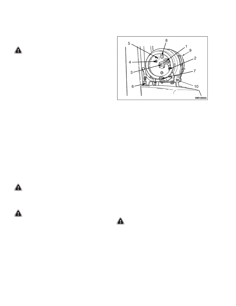
1.
Move lift truck to area where tanks are changed.
2.
Turn shutoff valve clockwise until valve is com-
pletely closed. See Figure 10.
3.
Run engine until it stops. Then turn key to OFF
position.
NOTE: SOME LPG TANKS HAVE AN AUXILIARY FILL
FITTING INSTEAD OF A PLUG FOR ITEM 4.
1.
SHUTOFF VALVE
2.
QUICK-DISCONNECT
FITTING
3.
FUEL GAUGE
4.
PLUG
5.
LIQUID LEVEL
INDICATOR
6.
RELIEF VALVE
7.
ALIGNMENT PIN
8.
TANK RELIEF
VALVE
9.
TANK LATCH
10. MOUNTING
BRACKET
Figure 10. LPG Tank
4.
Disconnect quick-disconnect fitting.
5.
Release tank latch and remove tank from
bracket.
INSTALL
1.
Before the tank is installed on the lift truck,
check operation of fuel gauge. See Figure 10.
Look at fuel gauge and move tank. The needle
of the gauge must move when the fuel moves. If
the needle does not move, a new tank must be
installed.
WARNING
Make sure that alignment pin extends through
correct hole in rim of LPG tank. The hose or
fittings can be damaged if the LPG tank is not
installed in the correct position. A damaged
hose or fitting can release LPG fuel and cause
an explosion hazard and fire hazard.
2.
Install LPG tank in its bracket so that alignment
pin is in correct hole in bracket. Close latches.
3.
Connect quick-disconnect fitting to shutoff valve
on tank. Use your hand to tighten fitting.
10

900 SRM 948
Carburetor Repair
4.
Turn shutoff valve counterclockwise to open
valve.
5.
Inspect fuel system for leaks when shutoff valve
is open. Frost on surface of tank, valves, or fit-
tings, or a strong odor of LPG indicates a leak.
6.
The shutoff valve on the tank must be closed
when the truck is not being used.
Relief Valve Repair
REMOVE AND INSTALL
WARNING
LPG can cause an explosion.
Do not cause
sparks or permit flammable material near
LPG system. Close fuel valve on tank. Discon-
nect negative battery cable to prevent sparks.
1.
Close shutoff valve on tank. See Figure 1.
2.
Slowly loosen hose fitting for relief valve. Let fuel
drain from fitting before removing relief valve.
3.
The valve cannot be repaired. If the valve is dam-
aged, install new valve. After installation, open
shutoff valve slowly and inspect system for leaks.
Carburetor Repair
REMOVE
WARNING
Before disconnecting any part of the LPG fuel
system, close shutoff valve on fuel tank. Run
engine until fuel lines are empty and engine
stops. If engine will not run, close shutoff valve
on fuel tank and release fuel slowly in a non-
hazardous area.
1.
Turn shutoff valve clockwise until valve is com-
pletely closed. See Figure 1.
2.
Run engine until it stops. Then turn key to OFF
position.
3.
Disconnect hose from air cleaner at bonnet.
4.
Disconnect both fuel inlet hoses (large hose to
carburetor and smaller hose to fuel injector).
5.
Disconnect hose to idle control actuator.
6.
Disconnect regulator hose.
7.
Disconnect power valve hose.
8.
Disconnect throttle cable at carburetor. Remove
carburetor from governor.
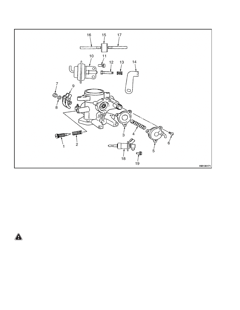
DISASSEMBLE
NOTE: Note the position of the diaphragm prior to
removal to aid in the installation.
1.
Disassemble power valve actuator by removing
three screws, cover, spring, and diaphragm from
carburetor. See Figure 11.
2.
Remove idle air bypass adjusting screw and
spring from carburetor.
3.
Remove two screws and idle control actuator
from carburetor.
4.
Remove nut, lockwasher, throttle cable link, and
lever from carburetor.
5.
If damaged, remove adjusting screw and spring
from lever.
11
Carburetor Repair
900 SRM 948
1.
IDLE AIR BYPASS ADJUSTING SCREW
2.
SPRING
3.
DIAPHRAGM
4.
SPRING
5.
COVER
6.
SCREW
7.
NUT
8.
LOCKWASHER
9.
THROTTLE CABLE LINK
10. IDLE CONTROL ACTUATOR
11. SCREW
12. IDLE-UP ADJUSTING SCREW
13. SPRING
14. LEVER
15. VALVE
16. VACUUM HOSE
17. VACUUM HOSE
18. FUEL INJECTOR
19. BOLT
Figure 11. Carburetor Parts
CLEAN
WARNING
Cleaning solvents can be flammable and toxic
and can cause skin irritation.
When using
cleaning solvents, always follow recommenda-
tions of manufacturer.
Make sure that all of carburetor parts are clean be-
fore assembly. Wash all parts (except diaphragm) in
solvent. Make sure that air passages in metering
valve are clean.
ASSEMBLE
1.
If removed, install spring and adjusting screw in
lever. See Figure 11.
2.
Install lever, throttle cable link, lockwasher, and
nut on carburetor. Tighten nut to 9 to 12 N•m
(80 to 106 lbf in).
3.
Install idle control actuator and two screws on
carburetor. Tighten screws to 3.4 to 4.4 N•m
(30 to 39 lbf in).
12
900 SRM 948
Fuel Injector Repair
4.
Install seal, fuel injector, and two screws on car-
buretor.
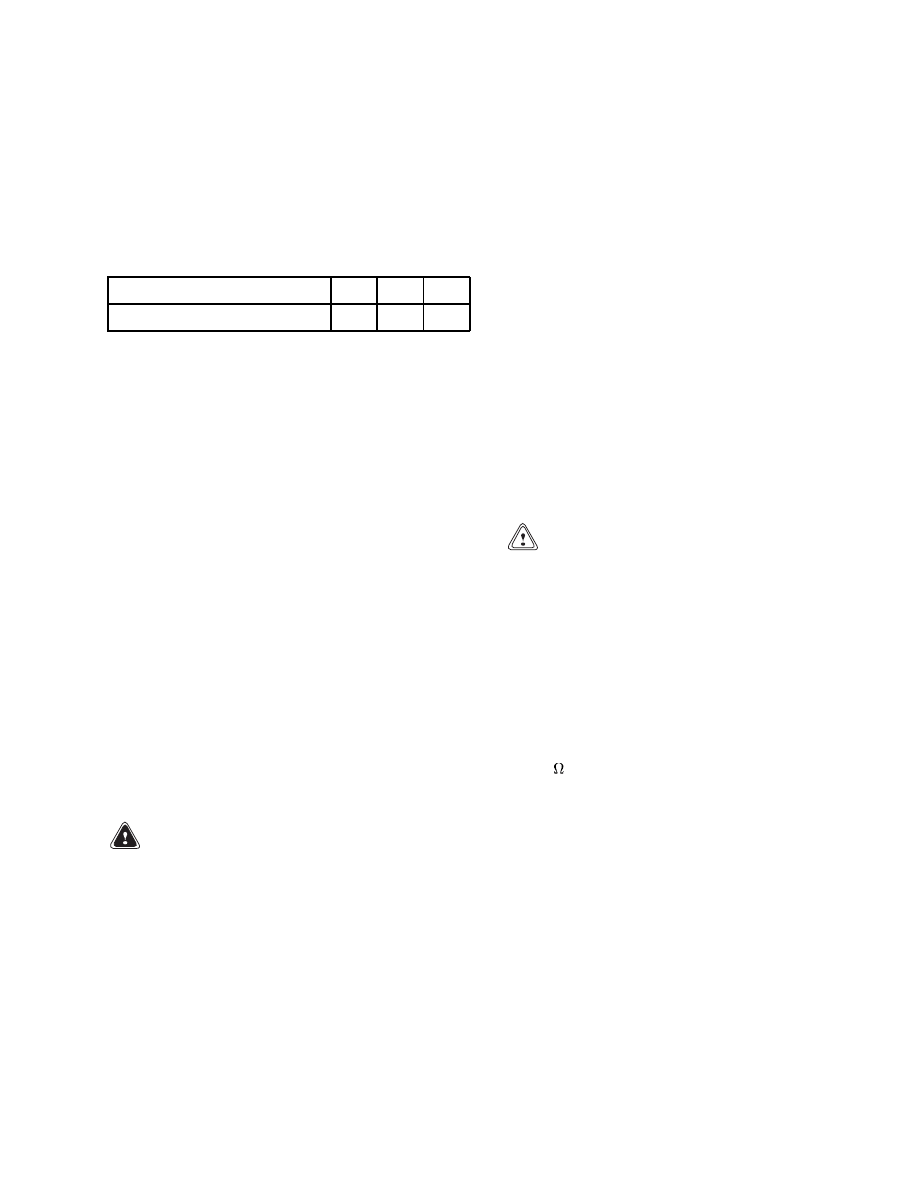
5.
Install idle air bypass adjusting screw into car-
buretor until screw is seated. Unscrew idle air
bypass adjusting screw the number of turns spec-
ified for the engine in the lift truck. See Table 1.
Table 1. Adjusting Screw
Engine
2.0
2.2
GM
Number of Loosening Turns
1
1
1
6.
Using two screws, install idle-up diaphragm on
carburetor.
7.
Install diaphragm (as noted during removal),
spring, cover, and three screws. Tighten screws
to 1.5 to 2.0 N•m (13 to 18 lbf in).
INSTALL
1.
Install new gasket on governor. See Figure 1.
Install carburetor on governor.
2.
Connect power valve hose.
3.
Connect hose from carburetor (spark advance
port) to distributor.
4.
Connect hose to idle control actuator.
5.
Connect both fuel inlet hoses (large hose to car-
buretor and smaller hose to fuel injector).
6.
Connect hose from air cleaner to bonnet.
7.
Connect throttle cable at carburetor. Check and
adjust throttle linkage as described in Throttle
Linkage Adjustment.
Fuel Injector Repair
REMOVE
1.
Turn shutoff valve clockwise until valve is com-
pletely closed. See Figure 11.
2.
Run engine until it stops, then turn key to OFF
position.
3.
Disconnect hose from fuel injector.
4.
Remove two mounting screws. Remove fuel in-
jector and seal from carburetor.
CLEAN AND INSPECT
1.
Use a clean cloth to remove any carbon deposits
around nozzle.
WARNING
Compressed air can move particles so that they
cause injury to the user or to other personnel.
Make sure that the path of the compressed air
is away from all personnel.
Wear protective
goggles or a face shield to prevent injury to the
eyes.
CAUTION
Do not insert wire more than 2.0 mm (0.08 in.)
into fuel injector nozzle. Otherwise, internal
parts of fuel injector may be damaged.
2.
Use a 1.2 mm (0.05 in.) diameter piece of steel
wire to clean out inside of nozzle. Insert and pull
out wire approximately 10 times while adding
343 to 490 kPa (50 to 71 psi) of pressure through
fuel supply port.
3.
Use an ohmmeter to check fuel injector coil for
continuity. The coil resistance should be 3.5 to
4.5 .
4.
Apply 12 VDC to both connector terminals of fuel
injector. A clicking sound should be heard.
INSTALL
1.
Insert seal and fuel injector into carburetor.
2.
Install two mounting screws. Tighten screws to
6.4 to 7.9 N•m (57 to 70 lbf in).
3.
Connect hose to fuel injector.
13
Regulator Repair
900 SRM 948
Governor Repair
REMOVE
1.
Disconnect vacuum hose from governor.
2.
Remove governor from intake manifold.
3.
Remove and discard gasket.
INSPECT
Inspect governor assembly and all hoses for any dam-
age. Replace any damaged components.
INSTALL
CAUTION
Make sure that all gasket material has been
cleaned
from
mating
surfaces
of
intake
manifold and governor. Gasket material left
on either surface will affect performance of lift
truck.
NOTE: The vacuum hoses installed on the carburetor
and governor are made of special high-temperature
material. If any of the hoses are replaced, make sure
that HYSTER APPROVED hoses are installed.
1.
Install new gasket on intake manifold.
2.
Install governor on intake manifold.
3.
Connect vacuum hose to governor.
Regulator Repair
REMOVE
WARNING
LPG can cause an explosion. Do not permit any
sparks or flames in work area.
1.
Close shutoff valve on tank. Run engine until it
stops. See Figure 1 and Figure 4.
2.
Disconnect electrical connectors from main sole-
noid valve and idle bypass solenoid valve respec-
tively.
3.
Put drain pan under drain valve for radiator.
Open drain valve so that coolant drains into pan.
4.
Disconnect cooling system hoses from regulator.
5.
Disconnect liquid LPG hose from regulator.
6.
Disconnect both LPG vapor hoses from regulator.
7.
Disconnect balance line from regulator. Remove
capscrews and regulator from mount.
INSTALL
1.
Connect balance line to regulator. Install regula-
tor and capscrews on mount.
2.
Connect both LPG vapor hoses to regulator.
3.
Connect liquid LPG hose to regulator.
4.
Connect cooling system hoses to regulator.
5.
Close drain valve and fill cooling system with
proper amount and mixture of coolant. See the
Periodic Maintenance manual for your lift
truck.
6.
Connect fitting from LPG tank to regulator as-
sembly. Connect electrical connectors from main
solenoid valve and idle bypass solenoid valve re-
spectively.
7.
Connect hose to carburetor. Open shutoff valve
on tank. Start engine.
14
900 SRM 948
Resistor Repair
Oxygen Sensor Repair
REMOVE AND INSTALL
1.
Disconnect electrical connector. Remove oxygen
sensor from exhaust pipe.
2.
Before installing the sensor, coat sensor spar-
ingly with an antiseize compound, then install
sensor. Tighten sensor to 39 N•m (29 lbf ft).
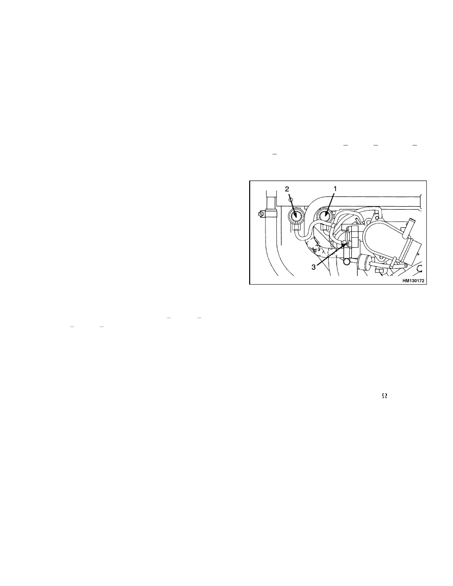
Vacuum Switches Repair
NOTE: Vacuum switch 1 has a white body with a gray
top. Vacuum switch 2 has a white body with a white
top. This procedure is used for both switches.
REMOVE AND INSTALL
1.
Disconnect vacuum hose.
2.
Disconnect electrical connector from vacuum
switch. See Figure 12.
3.
Remove mounting clamp and capscrew. Remove
vacuum switch.
4.
Install switch in reverse order.
INSPECT
1.
Connect an ohmmeter to vacuum switch.
2.
Apply vacuum to switch. The contacts of vac-
uum switch 1 should close at
16.0 to
20.0 kPa
( 4.7 to
5.9 inHg).
The contacts of vacuum
switch 2 should open at
29.0 to
33.3 kPa ( 8.5
to
9.8 inHg).
3.
Release vacuum. Switch contacts should open.
1.
VACUUM SWITCH 1 (IDLE)
2.
VACUUM SWITCH 2 (WIDE-OPEN THROTTLE)
3.
CARBURETOR
Figure 12. Vacuum Switches
Resistor Repair
REMOVE AND INSTALL
Disconnect electrical connector, then remove mount-
ing screw and resistor. Install resistor in reverse or-
der.
INSPECT
Use an ohmmeter to check resistor for continuity.
The coil resistance should be 5.4 to 6.6 .
15
Carburetor and New Regulator Adjustment
900 SRM 948
Carburetor and New Regulator Adjustment
IDLE SPEED AND FUEL MIXTURE
WARNING
LPG can cause an explosion. Do not permit any
sparks or open flames in work area.
1.
Warm engine, transmission, and hydraulic sys-
tem to normal operating temperatures. Make
sure that idle control actuator is not in contact
with idle-up adjusting screw.
2.
Check idle speed and engine timing. The timing
should be 8 BTDC @ 800 ±25 rpm GM 3.0L En-
gine, 9 BTDC @ 800 ±25 rpm S/H2.00-3.20XM
(S/H40-65XM), and 8
BTDC @ 725±25 rpm
S/H1.50-2.00XM (S/H25-40XM).
3.
If idle speed is not within specifications, adjust
idle air bypass adjusting screw on carburetor.
See Figure 13 and Figure 14.
NOTE: The following steps are for adjusting the fuel
mixture on a new replacement regulator that has not
been tamper-proofed. Do not perform this adjust-
ment on an old regulator. A CO% meter will be re-
quired.
4.
Disconnect electrical connector from fuel injector.
5.
Attach exhaust gas analyzer to raw gas emis-
sions port on exhaust pipe.
6.
Adjust idle speed to 725 rpm S/H1.50-2.00XM
(S/H25-40XM) or 800 rpm S/H2.00-3.20XM
(S/H40-65XM). If the reading on the CO% meter
is not between 0.06 and 0.13, replace regulator.
7.
On a new replacement regulator, adjust idle mix-
ture adjusting screw until reading on CO% meter
is between 0.06 and 0.13 while idle speed is at
725 rpm (S/H1.50-2.00XM [S/H25-40XM]) or 800
rpm (S/H2.00-3.20XM [S/H40-65XM]).
8.
Reconnect electrical connector to fuel injector. If
reading on CO% meter is not between 0.20 and
0.70, check fuel injector. See the procedures for
the fuel injector in the Fuel Injector Repair sec-
tion.
NOTE: For EPA Compliant engines go to Step 10.
9.
Install tamper-proof plug in idle mixture adjust-
ing screw port on regulator. The idle mixture ad-
justing screw can no longer be adjusted.
10. On EPA Compliant engines, install tamper-proof
plug in fuel filter assembly. The idle mixture ad-
justing screw can no longer be adjusted.
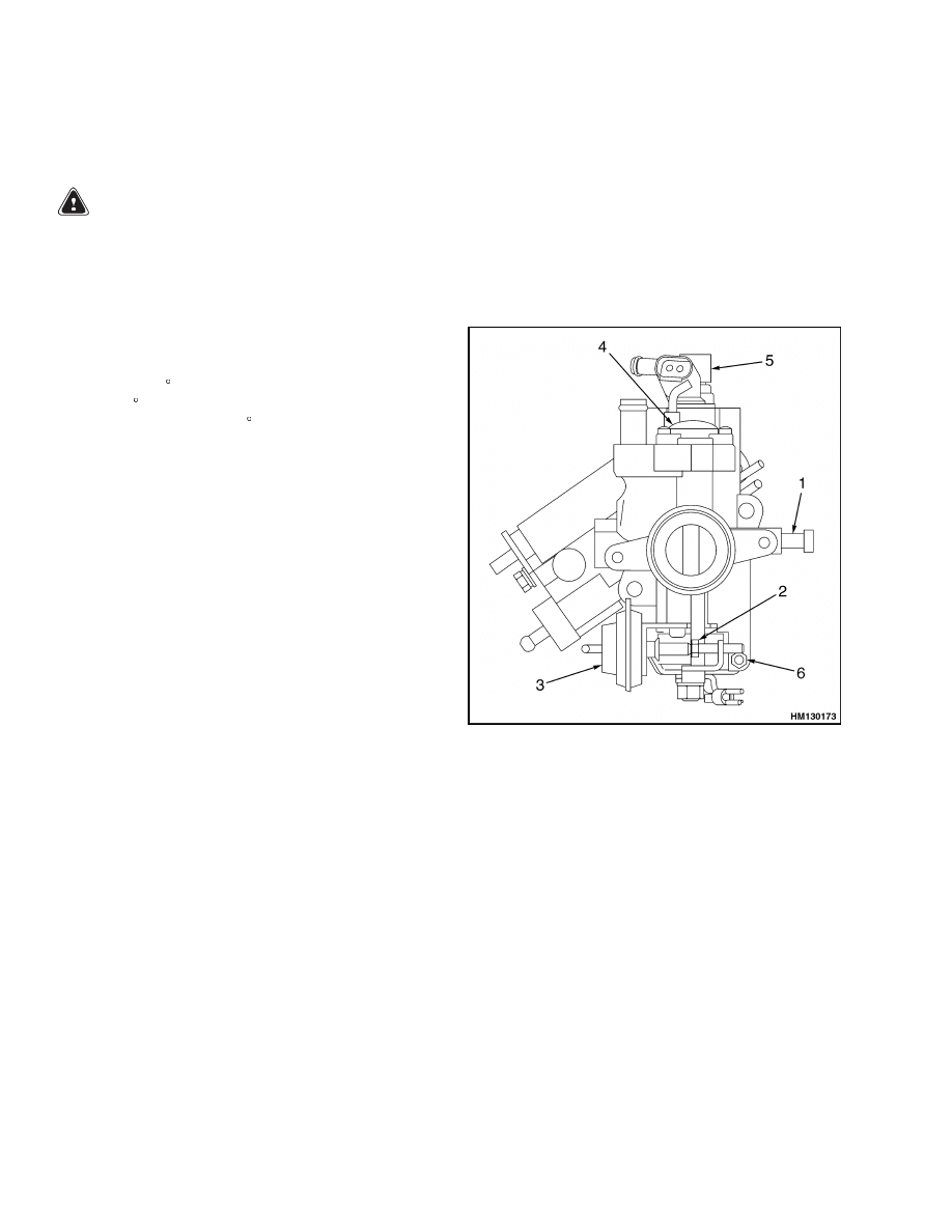
1.
IDLE AIR BYPASS ADJUSTING SCREW
2.
IDLE-UP ADJUSTING SCREW
3.
IDLE CONTROL ACTUATOR
4.
POWER VALVE ACTUATOR
5.
FUEL INJECTOR
6.
THROTTLE ADJUSTING SCREW
Figure 13. LPG Carburetor (Top View)
IDLE CONTROL ADJUSTMENT
1.
Warm engine, transmission, and hydraulic sys-
tem to normal operating temperatures. Make
sure that idle control actuator is not in contact
with idle-up adjusting screw. See Figure 13 and
Figure 14.
16
900 SRM 948
Governor Checks and Adjustments
2.
Set idle speed and idle mixture according to Idle
Speed and Fuel Mixture procedure.
3.
Adjust idle-up adjusting screw until there is 0.10
to 0.20 mm (0.004 to 0.008 in.) clearance between
screw and idle control actuator.
4.
Disconnect vacuum hose from idle control actua-
tor and check engine speed. If it is within idle-up
specification (1400 +0/ 150 rpm), no further ad-
justment is required. If engine speed exceeds
specification, adjust idle-up adjusting screw un-
til engine speed is within specification.
1.
CARBURETOR
2.
IDLE AIR BYPASS
ADJUSTING
SCREW
3.
GOVERNOR
4.
LOCKSCREW
5.
MAIN
ADJUSTMENT
WHEEL
6.
SECONDARY
ADJUSTING
SCREW
Figure 14. LPG Carburetor (Side View)
Governor Checks and Adjustments
The governor does not normally need adjustment.
If adjustment is necessary, do not turn adjusting
screws more than 1/4 turn at a time. See Figure 14
and Figure 15.
Otherwise, the governor can be
difficult to adjust.
CHECKS
Before making any adjustments to the governor,
check the following:
1.
Make sure that the mechanical, electrical, and
fuel systems are operating correctly.
2.
Make sure that tachometer will work with igni-
tion system.
3.
Make sure that air filter is clean and connected
to carburetor.
1.
SECONDARY ADJUSTING SCREW
2.
ADJUSTMENT SPRING
3.
MAIN ADJUSTMENT WHEEL
4.
LOCKSCREW
Figure 15. Governor
17
Throttle Linkage Adjustment
900 SRM 948
ADJUSTMENTS
With the engine at operating temperature, adjust
governor as follows:
1.
Remove lock wire from lockscrew.
Loosen
lockscrew. Apply parking brake.
2.
With no load on engine, run engine at full
open throttle to obtain maximum engine speed.
To adjust maximum no-load speed, hold sec-
ondary adjusting screw and turn main ad-
justment wheel.
Turn main adjusting screw
clockwise to increase engine speed or coun-
terclockwise to decrease engine speed.
Set
maximum engine speed to 2800 rpm Mazda and
GM 3.0L S2.00-3.20XM (S40-65XM), 2450 rpm
S/H1.50-2.00XMS (S/H25-40XMS), and 2900
rpm GM3.0L H2.00-3.20XM (H40-65XM).
3.
Tighten lockscrew.
4.
Run engine with throttle fully open, then pull on
tilt lever to load engine. The governor setting is
correct when the engine runs smoothly (without
speed changes) and the difference in speed be-
tween the load and no-load conditions is within
the limits of the specifications.
5.
If the engine speed changes, loosen lockscrew
and turn secondary adjusting screw 1/4 turn
clockwise. Set maximum no-load engine speed
by turning main adjustment wheel counterclock-
wise. Repeat this procedure until engine speed
is steady.
6.
If the engine speed difference between the load
and no-load conditions is greater than specified,
turn main adjustment wheel 1/4 turn clockwise.
Set maximum no-load engine speed by turning
secondary adjusting screw counterclockwise. Re-
peat this procedure until engine runs correctly.
7.
When governor adjustment is correct, tighten
lockscrew and install wire between lockscrew
and secondary adjusting screw.
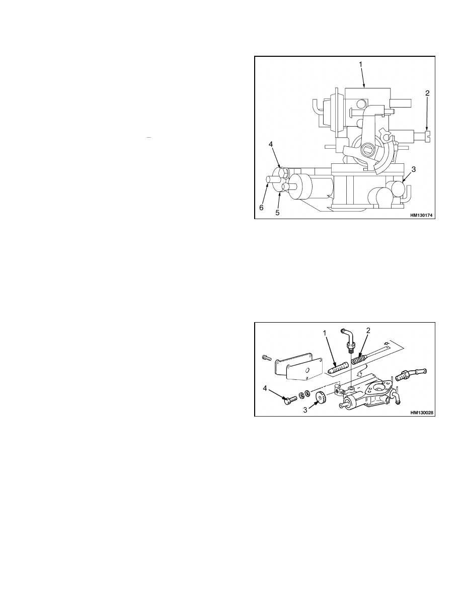
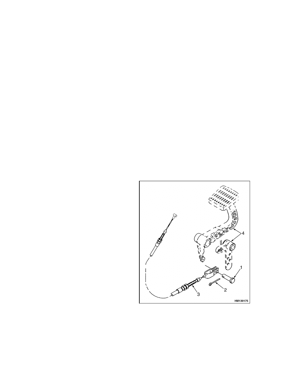
Throttle Linkage Adjustment
NOTE: Each time the throttle system is disassem-
bled, it is important to adjust the throttle cables.
1.
Adjust idle speed as described in Idle Control Ad-
justment.
2.
Make sure that throttle linkage at pedal assem-
bly is in correct position. See Figure 16.
3.
Push MONOTROL
®
or throttle pedal until it
stops against floor plate. Adjust throttle cable
so that pedal stops on floor plate just as throttle
plate reaches wide-open position. Use nuts at
pedal end of cable housing to change adjustment
of cable.
1.
PIN
2.
COTTER PIN
3.
THROTTLE CABLE
4.
PEDAL LINKAGE
ASSEMBLY
Figure 16. Throttle Cable Arrangement
18
900 SRM 948
Throttle Linkage Adjustment
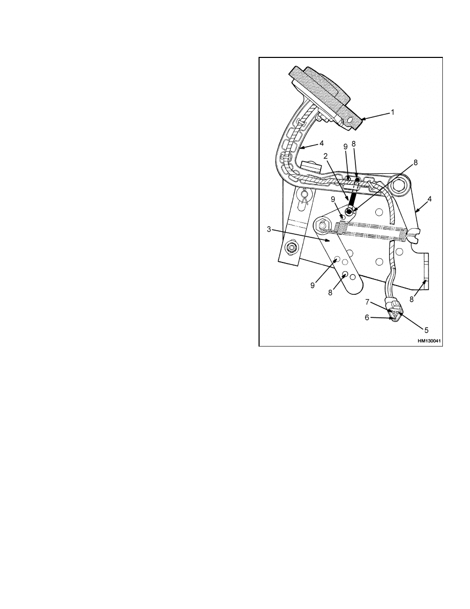
4.
Adjust pedal return stop so there is no tension
on throttle cable at idle position. See Figure 17.
To check this adjustment, perform the following
steps:
a. Run engine at idle speed. Make sure that
rod on idle control actuator is retracted and
throttle linkage is against idle air bypass ad-
justing screw.
b. When pedal return stop is in correct position,
tighten capscrew that holds stop to bracket.
NOTE: MONOTROL PEDAL SHOWN.
1.
PEDAL PAD
2.
LINK
3.
CRANK
4.
PEDAL FRAME
5.
FORWARD SOLENOID (BLACK WIRE)
6.
BATTERY (RED WIRE)
7.
REVERSE SOLENOID (YELLOW WIRE)
8.
CORRECT HOLES FOR LINKAGE H2.00-3.20XM
(H40-65XM)
9.
CORRECT HOLES FOR LINKAGE S2.00-3.20XM
(S40-65XM)
Figure 17. Throttle Arrangement
S/H2.00-3.20XM (S/H40-65XM)
19

Check Engine Light
900 SRM 948
MONOTROL Pedal Check
Slowly move the MONOTROL pedal pad from FORWARD to REVERSE and back to FORWARD. See Fig-
ure 17. There must be some movement of the pedal pad before the pedal frame moves and the throttle opens.
Check Engine Light
If this warning lamp is blinking while the lift truck
is in operation, there is an abnormal condition in the
air/fuel feedback system. Perform the following trou-
bleshooting checks to determine the specific problem.
NOTE: Most of these checks require the use of a volt-
meter or ohmmeter.
INSPECT WARNING LAMP
1.
Run engine at idle speed.
2.
Disconnect ECU check connector. Short-circuit
terminals A and B. If warning lamp blinks inter-
mittently (every 1.5 seconds), go to next check.
3.
If warning lamp blinks rapidly (every 0.25 sec-
ond), the problem is not in the feedback system.
Check wiring, ignition switch, and ECU. Repair
or replace components, as necessary.
CHECK FEEDBACK OPERATION
1.
Run engine at maximum rpm for 2 minutes in
order to warm up oxygen sensor, then set engine
speed at 2000 rpm.
2.
Disconnect ECU check connector.
Use ECU
check connector to check the signal voltage be-
tween terminals A and D. Keep terminal B open.
The signal voltage should be between 0 and 5 V.
3.
If signal voltage is within this range, go to next
check. If voltage is NOT within this range, in-
spect and repair wiring between the ECU and
connector. Go to the procedure Check Resistor.
CHECK VAC1 AND VAC2 SIGNALS
1.
Run engine at idle speed.
2.
Disconnect ECU check connector. Short-circuit
terminals A and B.
3.
Operate accelerator pedal and measure VAC1
signal voltage between terminals A and D. When
pedal is not pressed, signal should be 1 V or less.
When pedal is fully pressed, signal should be 4
V or more.
4.
If voltage is within these ranges, go to next step.
If voltage is NOT within these ranges, go to pro-
cedure Check Vacuum Switch 1.
5.
Short-circuit terminals A and B.
6.
Disconnect and reconnect vacuum hose and mea-
sure VAC2 signal voltage between terminals A
and C. When hose is connected, signal should be
1 V or less. When hose is disconnected, signal
should be 4 V or more.
7.
If voltage is within these ranges, go to next check.
8.
If voltage is NOT within these ranges, inspect
wiring between the ECU and connector. If wiring
is faulty, repair wiring and go to next check. If
wiring is OK, go to procedure Check Vacuum
Switch 2.
CHECK RESISTOR
1.
Stop engine.
2.
Use ohmmeter to check resistor for continuity.
Coil resistance should be 5.4 to 6.6 .
3.
If resistance is within this range, go to next
check. If resistance is NOT within this range, re-
place resistor and start troubleshooting process
again at Check Feedback Operation.
20

900 SRM 948
Check Engine Light
CHECK FUEL INJECTOR
1.
Inspect wiring between ECU and fuel injector.
If wiring is faulty, repair wiring and start trou-
bleshooting process again at Check Feedback Op-
eration.
2.
If wiring is OK, remove fuel injector for cleaning
and inspection. See the procedure for fuel injec-
tor in the Fuel Injector Repair section.
3.
If fuel injector does not meet specifications,
replace fuel injector and start troubleshooting
process again.
4.
If fuel injector meets specifications, install fuel
injector and go to next check.
CHECK OXYGEN SENSOR
1.
Check wiring between ECU and oxygen sensor.
If wiring is faulty, repair wiring.
2.
Perform Step 1 and Step 2 of the procedure Check
Feedback Operation. If signal voltage is within
specifications, check VAC1 signal and VAC2 sig-
nal again. If signal voltage is NOT within speci-
fications, replace oxygen sensor.
3.
Perform Step 1 and Step 2 of the procedure Check
Feedback Operation again. If signal voltage is
within specifications, air/fuel feedback system is
in normal operating condition. If signal voltage
is still NOT within specifications, replace ECU.
CHECK VACUUM SWITCH 1
1.
Inspect wiring between ECU and vacuum switch.
If wiring is faulty, repair wiring and go to next
check.
2.
If wiring is OK, remove vacuum switch for in-
spection. See the procedure for vacuum switches
in the Vacuum Switches Repair section.
3.
If vacuum switch does NOT meet specifications,
replace switch and go to next check.
4.
If vacuum switch meets specifications, inspect
vacuum hoses. Replace any damaged hoses and
go to next check. If no hoses are damaged, re-
place ECU before going to next check.
CHECK VACUUM SWITCH 2
1.
Inspect wiring between ECU and vacuum switch.
If wiring is faulty, repair wiring and start trou-
bleshooting process again at Check Feedback Op-
eration.
2.
If wiring is OK, remove vacuum switch for in-
spection.
See the procedure for the vacuum
switches in the Vacuum Switches Repair section.
3.
If vacuum switch does NOT meet specifications,
replace switch and start troubleshooting process
again.
If vacuum switch meets specifications, inspect
vacuum hoses. Replace any damaged hoses and
start troubleshooting process.
If no hoses are
damaged, replace ECU before starting trou-
bleshooting process again.
AFTER COMPLETING CHECKS
1.
Make sure that terminals A and B no longer have
a short circuit.
2.
Make sure that vacuum hoses and all electrical
wiring are connected.
3.
Disconnect negative battery terminal for more
than 30 seconds in order to clear memory of di-
agnostic system. Reconnect terminal.
4.
Run engine and check that "Check Engine" Light
does not come on. If light does come on, repeat
Step 3.
21

Troubleshooting
900 SRM 948
Troubleshooting
PROBLEM
POSSIBLE CAUSE
PROCEDURE OR ACTION
"Check
Engine"
light
is
blinking.
There is an abnormal condition in
air/fuel ratio feedback system.
Perform the checking procedures in
Check Engine Light.
Engine will not start.
Fuel tank is either empty or fuel
tank valve is closed.
Fill fuel tank or open fuel tank valve.
There is tar accumulation in regula-
tor.
Remove drain plug and drain tar
from regulator.
Fuel hose is either damaged or dis-
connected.
Replace damaged hose or reconnect
disconnected hose.
Fuel filter is clogged.
Replace fuel filter and clean tar from
regulator.
Main fuel shutoff solenoid valve does
not operate.
Disconnect solenoid from harness
and connect directly to battery. Lis-
ten for a clicking sound. If solenoid
does not energize, replace it with
new one.
Main fuel solenoid relay may be
faulty.
Disconnect relay and connect directly
to battery across terminals 85 and 86.
Listen for a clicking sound. If relay
does not energize, replace it with new
one.
Idle fuel shutoff solenoid valve does
not operate.
Disconnect solenoid from harness
and connect directly to battery. Lis-
ten for a clicking sound. If solenoid
does not energize, replace it with
new one.
Main fuel shutoff solenoid connector
is disconnected.
Connect main fuel solenoid connec-
tor.
Idle fuel shutoff solenoid connector is
disconnected.
Connect idle fuel solenoid connector.
Main fuel shutoff solenoid wire har-
ness is cut.
Repair or install new wiring harness.
Idle fuel shutoff solenoid wire har-
ness is cut.
Repair or install new wiring harness.
22

900 SRM 948
Troubleshooting
PROBLEM
POSSIBLE CAUSE
PROCEDURE OR ACTION
Engine will not start. (Cont).
Coil of idle fuel shutoff solenoid is
damaged.
Using an ohmmeter, measure resis-
tance between terminals. Measure-
ment should be 22.5 ±0.2
at 21 C
(70 F). Install new solenoid if mea-
surement is incorrect.
Coil of main fuel shutoff solenoid is
damaged.
Using an ohmmeter, measure resis-
tance between terminals. Measure-
ment should be 8.5 ±0.5
at 21 C
(70 F). Install new solenoid if mea-
surement is incorrect.
Main fuel shutoff solenoid valve is
clogged.
Clean main fuel shutoff solenoid
valve.
Idle fuel shutoff solenoid valve is
clogged.
Clean idle fuel shutoff solenoid valve.
Idle air bypass adjusting screw may
be clogged.
Clean or replace idle adjusting screw
as necessary.
Idle air bypass adjusting screw on
carburetor is out of adjustment.
Perform adjustment procedures lo-
cated in Carburetor and New Regu-
lator Adjustment.
Idle mixture adjusting screw on reg-
ulator is out of adjustment.
Replace regulator.
Primary diaphragm on regulator is
damaged.
Replace regulator.
Engine is hard to start.
Fuel hose is damaged.
Replace fuel hose.
A vacuum hose is either damaged or
disconnected.
Replace damaged hose or reconnect
disconnected hose.
Fuel filter is clogged.
Replace fuel filter.
There is tar accumulation in regula-
tor.
Remove drain plug and drain tar
from regulator.
There is an air leak between carbu-
retor and governor.
Replace gasket if it is broken or
tighten mounting nuts to correct
torque.
Main mixture passage of carburetor
may be clogged.
Replace carburetor.
Idle fuel solenoid valve does not seal.
Clean idle fuel solenoid or replace
with new one.
23

Troubleshooting
900 SRM 948
PROBLEM
POSSIBLE CAUSE
PROCEDURE OR ACTION
Engine is hard to start.
(Cont.)
There is an internal clogging of main
fuel solenoid.
Clean main fuel solenoid or replace
with new one.
Main fuel solenoid does not seal.
Clean main fuel solenoid or replace
with new one.
There is an internal clogging of idle
fuel solenoid.
Clean idle fuel solenoid or replace
with new one.
Idle air bypass adjusting screw on
carburetor is out of adjustment.
Perform procedures located in Car-
buretor and New Regulator Adjust-
ment.
Primary diaphragm on regulator is
damaged.
Replace regulator.
Idle mixture adjusting screw on
regulator is clogged or out of adjust-
ment.
Replace regulator.
Engine
does
not
idle
smoothly
(lean
fuel/air
mixture).
A vacuum hose is either damaged or
disconnected.
Replace damaged hose or reconnect
disconnected hose.
There is an air leak between carbu-
retor and governor.
Replace gasket if it is broken or
tighten mounting nuts to correct
torque.
There is tar accumulation in regula-
tor.
Remove drain plug and drain tar
from regulator.
Fuel filter is clogged.
Replace fuel filter and clean tar from
regulator.
Main fuel shutoff solenoid valve is
clogged.
Clean main fuel shutoff solenoid
valve.
Idle fuel shutoff solenoid valve is
clogged.
Clean idle fuel shutoff solenoid valve.
Idle mixture adjusting screw is
clogged.
Replace regulator.
Fuel injector is clogged.
Clean fuel injector.
Engine
does
not
idle
smoothly
(rich
fuel/air
mixture).
Resonator hose is either damaged or
disconnected.
Replace damaged hose or reconnect
disconnected hose.
Resonator is damaged.
Replace resonator.
24

900 SRM 948
Troubleshooting
PROBLEM
POSSIBLE CAUSE
PROCEDURE OR ACTION
Engine
does
not
idle
smoothly
(rich
fuel/air
mixture). (Cont.)
Fuel injector pulse rate does not drop
at idle.
Check fuel injector and wiring, vac-
uum hose, vacuum switch 1, oxygen
sensor, and ECU.
Idle mixture adjusting screw on reg-
ulator is out of adjustment.
Replace regulator.
Engine
does
not
idle
smoothly
(idle
speed
too
low).
Idle air bypass adjusting screw on
carburetor may be clogged.
Clean or replace idle air bypass ad-
justing screw and clean tar from car-
buretor.
Idle air bypass adjusting screw on
carburetor is out of adjustment.
Perform adjustment procedures lo-
cated in Carburetor and New Regu-
lator Adjustment.
Idle mixture adjusting screw on reg-
ulator is out of adjustment.
Replace regulator.
Engine
does
not
idle
smoothly
(idle
speed
too
high).
Idle air bypass adjusting screw on
carburetor is out of adjustment.
Perform adjustment procedures lo-
cated in Carburetor and New Regu-
lator Adjustment.
Idle mixture adjusting screw on reg-
ulator is out of adjustment.
Replace regulator.
There is engine hesitation,
surge, knocking, or loss of
power due to lean or rich
fuel/air mixture.
A vacuum hose is either damaged or
disconnected.
Replace damaged hose or reconnect
disconnected hose.
Main fuel shutoff solenoid valve is
clogged.
Clean main fuel shutoff solenoid
valve.
Idle fuel shutoff solenoid valve is
clogged.
Clean idle fuel shutoff solenoid valve.
Fuel hose is damaged.
Replace fuel hose.
Fuel filter is clogged.
Replace fuel filter and clean tar from
regulator.
Idle mixture adjusting screw may be
clogged.
Clean or replace regulator as neces-
sary.
There is tar accumulation in regula-
tor.
Remove drain plug and drain tar
from regulator.
25

Troubleshooting
900 SRM 948
PROBLEM
POSSIBLE CAUSE
PROCEDURE OR ACTION
There is engine hesitation,
surge, knocking, or loss of
power due to lean or rich
fuel/air mixture. (Cont.)
There is an air leak between carbu-
retor and governor.
Replace gasket if it is broken or
tighten mounting nuts to correct
torque.
Carburetor is out of calibration.
If out of calibration, replace carbure-
tor.
Idle mixture adjusting screw may be
out of adjustment.
Replace regulator.
Coolant hose has become clogged or
disconnected, causing regulator to
become frozen.
Clear obstruction from coolant hose
or reconnect coolant hose.
Resonator is damaged.
Replace resonator.
Resonator hose is either damaged or
disconnected.
Replace damaged hose or reconnect
disconnected hose.
There
is
no
clearance
between
idle-up adjusting screw and idle
control actuator.
Adjust idle-up adjusting screw.
Fuel injector is clogged with tar.
Clean the fuel injector.
Fuel injector is delivering too much
fuel or too little/no fuel.
Check fuel injector and wiring, vac-
uum hose, vacuum switch 1, oxygen
sensor, and ECU.
Engine stops running during
deceleration,
immediately
after engine startup, imme-
diately
after
acceleration,
during a sharp turn, or dur-
ing load up/down operations
due to lean or rich fuel/air
mixture.
Main fuel shutoff solenoid valve is
clogged.
Clean main fuel shutoff solenoid
valve.
Idle fuel shutoff solenoid valve is
clogged.
Clean idle fuel shutoff solenoid valve.
Fuel hose is damaged.
Replace fuel hose.
Fuel filter is clogged.
Replace fuel filter and clean tar from
regulator.
Idle mixture adjusting screw may be
clogged.
Replace regulator.
26

900 SRM 948
Troubleshooting
PROBLEM
POSSIBLE CAUSE
PROCEDURE OR ACTION
Engine stops running during
deceleration,
immediately
after engine startup, imme-
diately
after
acceleration,
during a sharp turn, or dur-
ing load up/down operations
due to lean or rich fuel/air
mixture. (Cont.)
There is tar accumulation in regula-
tor.
Remove drain plug and drain tar
from regulator.
There is an air leak between carbu-
retor and governor.
Replace gasket if it is broken or
tighten mounting nuts to correct
torque.
Vacuum hose is either damaged or
disconnected.
Replace damaged hose or reconnect
disconnected hose.
Carburetor may be out of calibration.
If out of calibration, replace carbure-
tor.
Idle mixture adjusting screw may be
out of adjustment.
Replace regulator.
Engine
hesitation,
surge,
knocking, or loss of power
due to lean or rich fuel/air
mixture or loss of air.
Coolant hose has become clogged or
disconnected, causing regulator to
become overcooled.
Clear obstruction from coolant hose
or reconnect coolant hose.
Regulator has become overcooled af-
ter engine has reached normal oper-
ating temperature.
Replace regulator.
Resonator is damaged.
Replace resonator.
Resonator hose is either damaged or
disconnected.
Replace damaged hose or reconnect
disconnected hose.
Engine continues to run af-
ter being shut down (diesel-
ing).
Idle fuel shutoff solenoid valve does
not operate.
Disconnect solenoid from harness
and connect directly to battery. Lis-
ten for a clicking sound. If solenoid
does not energize, replace with new
one.
Idle fuel shutoff solenoid valve is
clogged.
Clean idle fuel shutoff solenoid valve.
27

NOTES
____________________________________________________________
____________________________________________________________
____________________________________________________________
____________________________________________________________
____________________________________________________________
____________________________________________________________
____________________________________________________________
____________________________________________________________
____________________________________________________________
____________________________________________________________
____________________________________________________________
____________________________________________________________
____________________________________________________________
____________________________________________________________
____________________________________________________________
____________________________________________________________
____________________________________________________________
____________________________________________________________
____________________________________________________________
____________________________________________________________
28


TECHNICAL PUBLICATIONS
900 SRM 948
WIP (11/04)(2/04)(11/03)(8/02)(1/02)(1/01) Printed in United Kingdom
Document Outline
- toc
- LPG Fuel System
- Safety Precautions Maintenance and Repair
- General
- Description and Operation
- Hoses Replacement
- LPG Tank Repair
- Relief Valve Repair
- Carburetor Repair
- Fuel Injector Repair
- Governor Repair
- Regulator Repair
- Oxygen Sensor Repair
- Vacuum Switches Repair
- Resistor Repair
- Carburetor and New Regulator Adjustment
- Governor Checks and Adjustments
- Throttle Linkage Adjustment
- MONOTROL Pedal Check
- Check Engine Light
- Troubleshooting
- tables
Wyszukiwarka
Podobne podstrony:
1580506 0900SRM1124 (05 2005) UK EN
1580516 2100SRM1139 (09 2005) UK EN
1482638 8000SRM0805 (09 2005) UK EN
1510478 8000SRM0988 (06 2005) UK EN
1568204 0700SRM1159 (08 2005) UK EN
1566043 0620SRM1115 (08 2005) UK EN
897653 1800SRM0566 (04 2005) UK EN
1459370 1600SRM0720 (07 2005) UK EN
897953 1600SRM0639 (03 2005) UK EN
910091 1900SRM0097 (08 2005) UK EN
1598459 1900SRM1213 (03 2005) UK EN
1494953 1400SRM0944 (09 2003) UK EN
1596602 0100SRM1200 (07 2005) UK EN
897394 1900SRM0453 (09 2003) UK EN
więcej podobnych podstron