CYLINDER REPAIR
S30FT, S35FT, S40FTS [E010];
E1.50-2.00XM (E25-35Z, E40ZS) [E114];
H1.6FT, H1.8FT, H2.0FTS
(H30FT, H35FT, H40FTS) [F001];
S2.0-3.5FT (S40-70FT, S55FTS) [F187];
J1.60-2.00XMT (J30-40ZT) [J160];
H2.0-3.5FT (H40-70FT) [L177]
PART NO. 1580516
2100 SRM 1139

SAFETY PRECAUTIONS
MAINTENANCE AND REPAIR
• When lifting parts or assemblies, make sure all slings, chains, or cables are correctly
fastened, and that the load being lifted is balanced. Make sure the crane, cables, and
chains have the capacity to support the weight of the load.
• Do not lift heavy parts by hand, use a lifting mechanism.
• Wear safety glasses.
• DISCONNECT THE BATTERY CONNECTOR before doing any maintenance or repair
on electric lift trucks. Disconnect the battery ground cable on internal combustion lift
trucks.
• Always use correct blocks to prevent the unit from rolling or falling. See HOW TO PUT
THE LIFT TRUCK ON BLOCKS in the Operating Manual or the Periodic Mainte-
nance section.
• Keep the unit clean and the working area clean and orderly.
• Use the correct tools for the job.
• Keep the tools clean and in good condition.
• Always use HYSTER APPROVED parts when making repairs. Replacement parts
must meet or exceed the specifications of the original equipment manufacturer.
• Make sure all nuts, bolts, snap rings, and other fastening devices are removed before
using force to remove parts.
• Always fasten a DO NOT OPERATE tag to the controls of the unit when making repairs,
or if the unit needs repairs.
• Be sure to follow the WARNING and CAUTION notes in the instructions.
• Gasoline, Liquid Petroleum Gas (LPG), Compressed Natural Gas (CNG), and Diesel fuel
are flammable. Be sure to follow the necessary safety precautions when handling these
fuels and when working on these fuel systems.
• Batteries generate flammable gas when they are being charged. Keep fire and sparks
away from the area. Make sure the area is well ventilated.
NOTE: The following symbols and words indicate safety information in this
manual:
WARNING
Indicates a condition that can cause immediate death or injury!
CAUTION
Indicates a condition that can cause property damage!

Cylinder Repair
Table of Contents
TABLE OF CONTENTS
General ...............................................................................................................................................................
Description .........................................................................................................................................................
Safety Procedures When Working Near Mast..................................................................................................
Tilt Cylinder Repair ...........................................................................................................................................
Remove ...........................................................................................................................................................
Disassemble ...................................................................................................................................................
Inspect ............................................................................................................................................................
Clean ..............................................................................................................................................................
Assemble ........................................................................................................................................................
Install .............................................................................................................................................................
Tilt Cylinders, Adjust ....................................................................................................................................
Tilt Cylinder Leak Check for Two-Stage LFL, Two-Stage FFL, and Three-Stage FFL.............................
Tilt Cylinder Leak Check for the Four-Stage Full Free-Lift.......................................................................
Torque Specifications.....................................................................................................................................
Piston Rod..................................................................................................................................................
Gland..........................................................................................................................................................
Tilt Cylinder Mounting Capscrew ............................................................................................................
Tilt Cylinder Rod End Capscrew ..............................................................................................................
Lift Cylinder Repair...........................................................................................................................................
Main Lift Cylinders, Remove ........................................................................................................................
Free-Lift Cylinder, Remove ...........................................................................................................................
Free-Lift and Main Lift Cylinders, Disassemble .........................................................................................
Two-Stage FFL Cylinder, Disassemble.........................................................................................................
Inspect ............................................................................................................................................................
Clean ..............................................................................................................................................................
Full Free-Lift and Main Lift Cylinders, Assemble ......................................................................................
Two-Stage FFL and Main Lift Cylinders, Assemble....................................................................................
Main Lift Cylinders, Install ..........................................................................................................................
Free-Lift Cylinder, Install .............................................................................................................................
Torque Specifications.....................................................................................................................................
Lift Cylinders Leak Check ............................................................................................................................
This section is for the following models:
S30FT, S35FT, S40FTS [E010];
E1.50-2.00XM (E25-35Z, E40ZS) [E114];
H1.6FT, H1.8FT, H2.0FTS (H30FT, H35FT, H40FTS) [F001];
S2.0-3.5FT (S40-70FT, S55FTS) [F187];
J1.60-2.00XMT (J30-40ZT) [J160];
H2.0-3.5FT (H40-70FT) [L177]
©2005 HYSTER COMPANY
i

"THE
QUALITY
KEEPERS"
HYSTER
APPROVED
PARTS

2100 SRM 1139
Safety Procedures When Working Near Mast
General
This section has a description and the repair proce-
dures for several different types of cylinders. The
number and the design of the parts can be different,
but the operation of the cylinders is the same.
Description
This manual covers many different types of cylin-
ders. Each cylinder will be described in detail.
Tilt cylinders are fastened between the frame of the
lift truck and the outer weldment of the mast to
change the angle of the mast and forks.
Two single-stage main lift cylinders and a free-lift
cylinder are used to raise the carriage and extend the
mast weldments.
The two main lift cylinders are installed at the back
of the outer mast. The base of each lift cylinder sits
on a mount at the bottom crossmember of the outer
mast. The top of each main lift cylinder rod fits into a
guide on the top crossmember of the inner mast. The
free-lift cylinder is installed in the inner mast. Each
of the lift cylinders has an internal lowering control
valve. A single external lowering control valve is con-
nected by tubing and hoses to all the lift cylinders.
NOTE: On lift truck models S2.0-3.5FT (S40-70FT,
S55FTS) (F187) and H2.0-3.5FT (H40-70FT) (L177)
there are two free-lift chains and chain sheaves.
On lift truck models S30FT, S35FT, S40FTS
(E010), E1.50-2.00XM (E25-35Z, E40ZS) (E114),
J1.60-2.00XMT (J30-40ZT) (J160), and H1.6FT,
H1.8FT, H2.0FTS (H30FT, H35FT, H40FTS) (F001)
there is one free-lift chain and chain sheave. The
description below applies to all trucks.
The free-lift chains connect at one end of the mid-
crossmember of the inner mast. Two chain sheaves
are installed on a crosshead on the rod of the free-
lift cylinder. The chains then go over sheaves on the
crosshead and connect to the carriage.
Safety Procedures When Working Near Mast
The following procedures MUST be used when in-
specting or working near the mast. Additional pre-
cautions and procedures can be required when re-
pairing or removing the mast.
WARNING
Mast parts are heavy and can move. Distances
between parts are small.
Serious injury or
death can result if part of the body is hit by
parts of the mast or the carriage.
• Never put any part of the body into or under
the mast or carriage unless all parts are com-
pletely lowered or a safety chain is installed.
Also make sure that the power is OFF and the
key is removed. Put a DO NOT OPERATE tag
in the operator’s compartment. Disconnect
the battery and put a tag or lock on the bat-
tery connector.
• Be careful of the forks.
When the mast is
raised, the forks can be at a height to cause
an injury.
• DO NOT climb on the mast or lift truck at any
time. Use a ladder or personnel lift to work
on the mast.
• DO NOT use blocks to support the mast weld-
ments nor to restrain their movement.
• Mast repairs require disassembly and re-
moval of parts and can require removal of
the mast or carriage. Follow the repair pro-
cedures in this section.
WHEN WORKING NEAR THE MAST ALWAYS:
• Lower the mast and carriage completely.
Push the lift/lower control lever forward and
make sure there is no movement in the mast.
Make sure that all parts of the mast that
move are fully lowered.
OR
• If parts of the mast must be in a raised po-
sition, install a safety chain to restrain the
moving parts of the mast. Connect moving
parts to a part that does not move. Follow
these procedures:
1.
Put mast in vertical position.
1

Safety Procedures When Working Near Mast
2100 SRM 1139
2.
Raise mast to align bottom crossmember of weld-
ment that moves in outer weldment with cross-
member on outer weldment. On the two-stage
and free-lift mast, the moving part is the inner
weldment. On the three-stage mast, it is the in-
termediate weldment. On the four-stage mast, it
is the first intermediate weldment. See Figure 1.
3.
Use a 3/8-inch minimum safety chain with a hook
to fasten the crossmembers together so the mov-
able member cannot lower. Put hook on back side
of mast. Make sure hook is completely engaged
with a link in the chain. Make sure safety chain
does not touch lift chains or chain sheaves, tubes,
hoses, fittings, or other parts on the mast.
4.
Lower mast until there is tension in safety chain
and free-lift cylinder (two-stage full free-lift,
three-stage, and four-stage) is completely re-
tracted. If running, turn the power OFF. Apply
the parking brake. Install a DO NOT REMOVE
tag on the safety chain(s).
5.
Install another safety chain (3/8-in. minimum)
between the top or bottom crossmember of the
carriage bar and a crossmember on the outer
weldment.
NOTE: Apply the parking brake. After lowering or
restraining the mast, shut off the power, and remove
key. Put a DO NOT OPERATE tag in the operator’s
compartment. Disconnect battery and put a tag or
lock on battery connector.
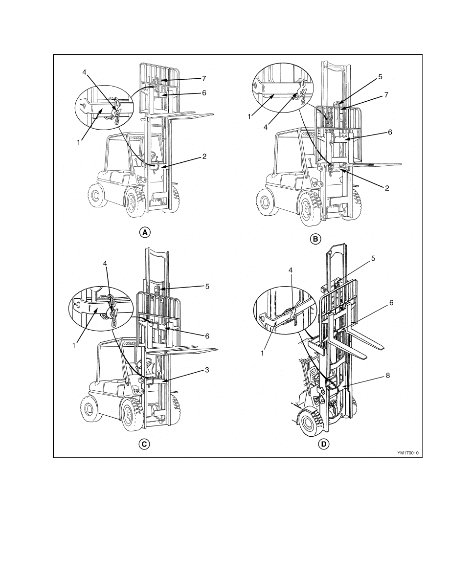
Legend for Figure 1
A. TWO-STAGE LFL MAST
B. TWO-STAGE FFL MAST
C. THREE-STAGE FFL MAST
D. FOUR-STAGE FFL MAST
1.
OUTER WELDMENT
2.
INNER WELDMENT
3.
INTERMEDIATE WELDMENT
4.
HOOK
5.
FREE-LIFT CYLINDER
6.
CARRIAGE BAR
7.
CROSSMEMBER
8.
FIRST INTERMEDIATE WELDMENT
2
2100 SRM 1139
Safety Procedures When Working Near Mast
Figure 1. Two-Stage LFL, Two-Stage FFL, Three-Stage FFL, and Four-Stage FFL Masts
3
Tilt Cylinder Repair
2100 SRM 1139
Tilt Cylinder Repair
REMOVE
WARNING
Before removing the tilt cylinder(s), tilt the
mast forward. Use a chain to hold the mast to
the frame and prevent the mast from moving
forward.
WARNING
Do not push the anchor pins out of the rod end
with your fingers. Do not permit the tilt cylin-
ders to drop and cause damage.
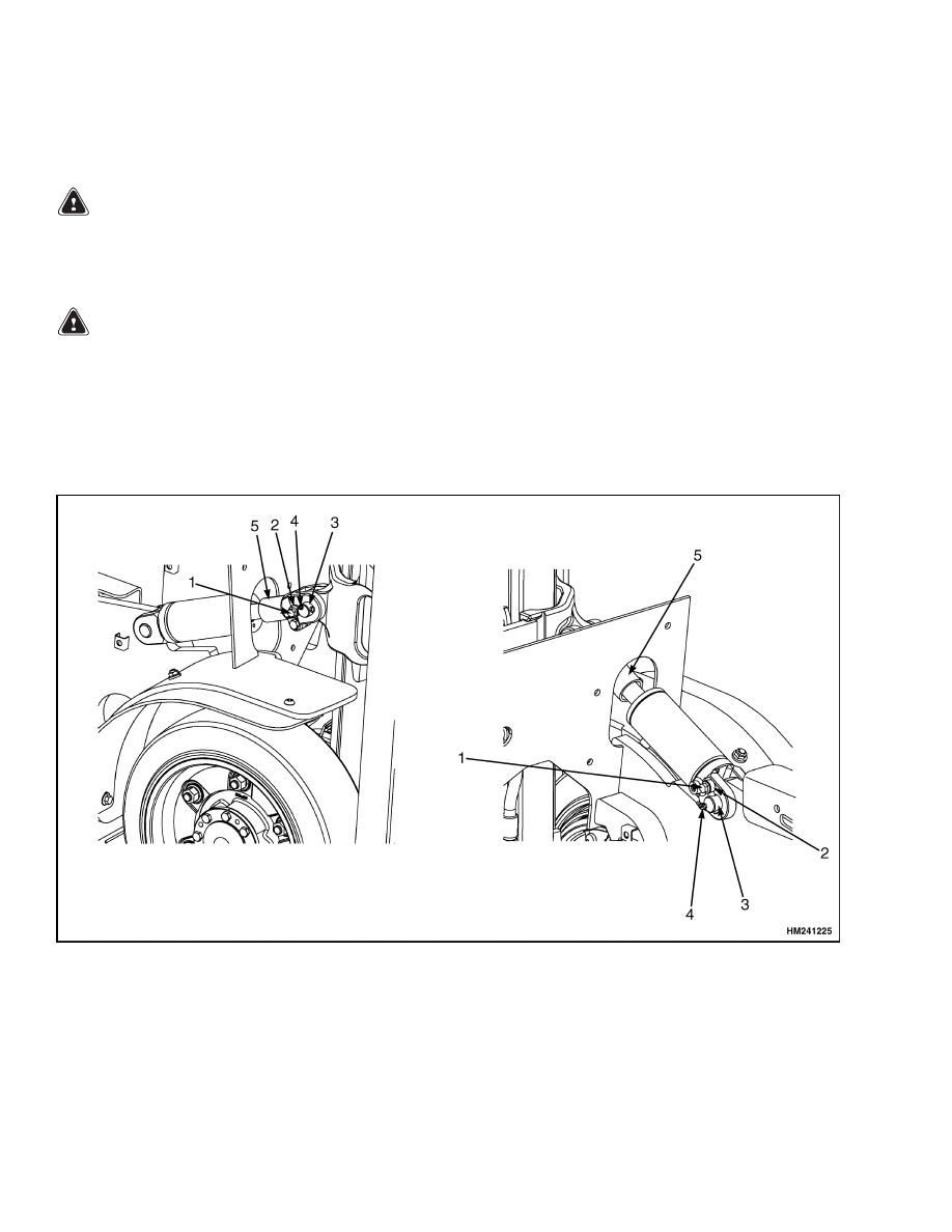
1.
At the mast, remove the capscrew and retainer
from the anchor pin. Using a drift pin or similar
tool, push the anchor pin out of the rod end. See
Figure 2.
2.
Stroke cylinder to the full backtilt position.
3.
Disconnect the hydraulic lines at the tilt cylin-
der. Install caps on the hydraulic lines and in
the cylinder ports.
4.
Use a lifting device to move large tilt cylinders.
Remove the capscrew and retainer from the an-
chor pin. Using a drift pin or similar tool, push
the anchor pin out of the frame.
5.
Using a lifting device, remove the tilt cylinder
from the lift truck.
6.
Repeat above steps for the remaining tilt cylin-
der.
NOTE: HYDRAULIC HOSES ARE SHOWN DISCONNECTED FOR CLARITY.
1.
CAPSCREW
2.
RETAINER
3.
LUBRICATION FITTING
4.
ANCHOR PIN
5.
TILT SPACER
Figure 2. Tilt Cylinder Removal
4
2100 SRM 1139
Tilt Cylinder Repair
DISASSEMBLE
NOTE: The following steps have detailed disassembly
instructions. Perform only those steps required to
repair the tilt cylinder.
NOTE: Note the position of the rod end and number
of turns used to remove the rod end.
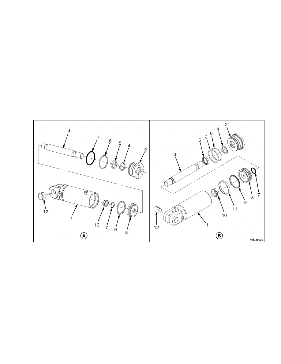
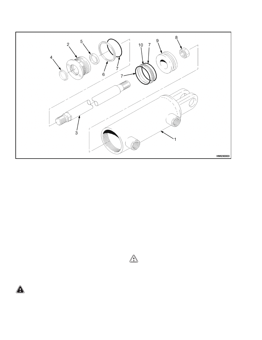
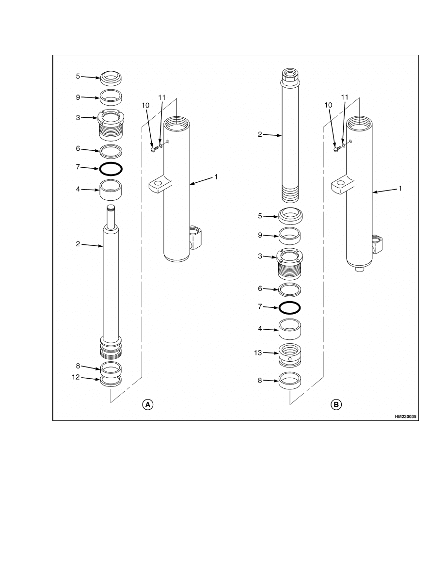
1.
Put the tilt cylinder in a soft jaw vise. Remove
the rod end and, if equipped, tilt spacer from the
rod. See Figure 3 or Figure 4.
2.
Using a pin-type spanner wrench, Remove the
gland from the tilt cylinder. Remove the rod and
piston assembly from the cylinder.
NOTE: To prevent damage to sealing surfaces, use
brass tools when removing seals and O-rings.
3.
Remove and discard the O-ring, backup ring,
seal, and wiper from the gland.
NOTE: Perform Step 4 only if the piston or rod has
been damaged.
4.
Place the rod in a soft-jaw vise and remove the
piston from the rod.
5.
Remove and discard the O-ring and piston seal
from the piston.
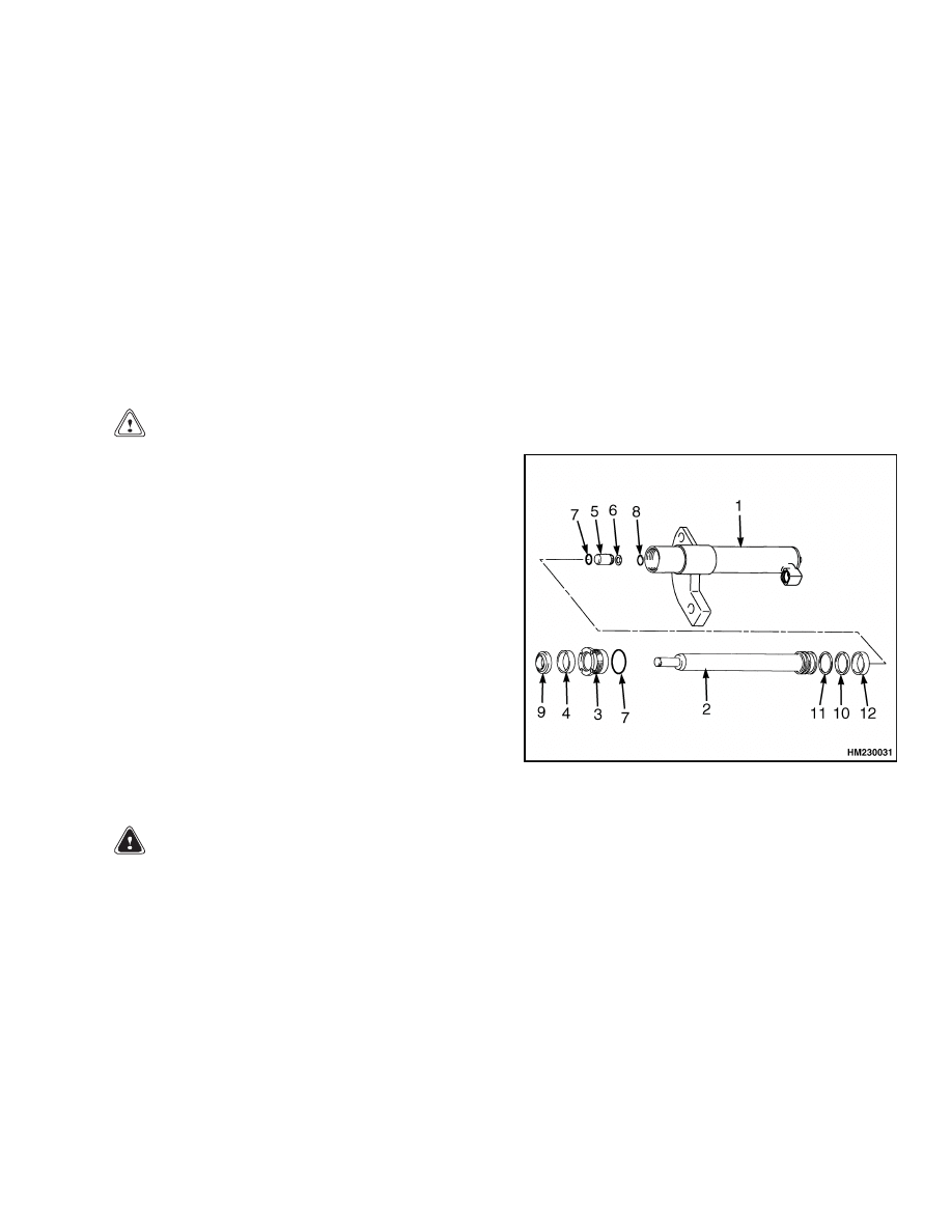
A. S2.0-2.5FT (S40-S55FT, S55FTS) (F187),
S30FT, S35FT, S40FTS (E010), H1.6FT, H1.8FT,
H2.0FTS (H30FT, H35FT, H40FTS) (F001), AND
H2.0-2.5FT (H40-50FT) (L177)
B. S3.0-3.5FT (S60-S70FT) (F187) AND H3.0-3.5FT
(H60-70FT) (L177)
1.
TUBE
2.
GLAND
3.
ROD
4.
WIPER RING
5.
SEAL
6.
BACKUP RING
7.
O-RING
8.
PISTON
9.
PISTON SEAL
10. NUT
11. WEAR RING
12. BUSHING
Figure 3. Tilt Cylinder
5
Tilt Cylinder Repair
2100 SRM 1139
1.
CYLINDER SHELL
2.
RETAINER
3.
ROD
4.
WIPER RING
5.
SEAL
6.
BACKUP RING
7.
O-RING
8.
NUT
9.
PISTON
10. PISTON SEAL
Figure 4. Tilt Cylinder - E1.50-2.00XM (E25-35Z, E40ZS) (E114) and J1.60-2.00XMT (J30-40ZT) (J160)
INSPECT
Inspect the gland for damage to the threads and the
seal surfaces. Replace the gland if damaged.
Inspect the piston for any damage to the seal surfaces
and replace if damaged.
Inspect the rod for damage to the rod surface and
ensure that the rod is not bent. Replace the rod if
found to be damaged.
Inspect the inner surface of the cylinder tube for
damage. If the tube is found to be damaged, replace
the cylinder.
CLEAN
WARNING
Cleaning solvents can be flammable and toxic
and can cause skin irritation.
When using
cleaning solvents, always follow the solvent
manufacturer’s recommended safety proce-
dures.
Compressed air can move particles so they
cause injury to the user or to other personnel.
Make sure the path of the compressed air is
away from all personnel. Wear protective gog-
gles or a face shield to prevent injury to the
eyes.
CAUTION
Do not allow cleaning solvent to come in con-
tact with rubber components, as it will damage
those components.
Clean all metal parts in solvent and dry with com-
pressed air.
6

2100 SRM 1139
Tilt Cylinder Repair
ASSEMBLE
NOTE: To prevent damage to sealing surfaces, use
brass tools when installing seals and O-rings.
1.
Install a new piston seal and O-ring on the pis-
ton. See Figure 3.
NOTE: Perform Step 2 only if the piston was removed
from the rod.
2.
Place the rod in a soft-jaw vise, and install the
piston on the rod and tighten the nut to
• 170 to 220 N•m (125 to 163 lbf ft) on lift truck
models
S2.0-2.5FT
(S40-S55FT,
S55FTS)
(F187),
S30FT,
S35FT,
S40FTS
(E010),
E1.50-2.00XM
(E25-35Z,
E40ZS)
(E114),
H1.6FT, H1.8FT, H2.0FTS (H30FT, H35FT,
H40FTS) (F001), and H2.0-2.5FT (H40-50FT)
(L177)
• 320 to 400 N•m (240 to 295 lbf ft) on lift truck
models S3.0-3.5FT (S60-S70FT) (F187) and
H3.0-3.5FT (H60-70FT) (L177)
• 163 to 190 N•m (120 to 140 lbf ft) on lift truck
models J1.60-2.00XMT (J30-40ZT) (J160)
3.
Install a new wiper, seal, backup ring, and O-ring
on the gland.
4.
Install the rod and piston assembly in the cylin-
der. Using a pin-type spanner, install the gland
in the cylinder. Tighten the gland to
• 170 to 237 N•m (125 to 175
lbf ft) for lift
truck models S2.0-2.5FT (S40-S55FT, S55FTS)
(F187) and H2.0-2.5FT (H40-50FT) (L177)
• 163 to 190 N•m (120 to 140
lbf ft) for
lift truck models S30FT, S35FT, S40FTS
(E010),
E1.50-2.00XM
(E25-35Z,
E40ZS)
(E114), J1.60-2.00XMT (J30-40ZT) (J160), and
H1.6FT, H1.8FT, H2.0FTS (H30FT, H35FT,
H40FTS) (F001).
• 400 to 500 N•m (295 to 370
lbf ft) for lift
truck models S3.0-3.5FT (S60-S70FT) (F187)
and H3.0-3.5FT (H60-70FT) (L177)
5.
Place the cylinder in a soft-jaw vise and install
the tilt spacer, if equipped, and rod end on the rod
as noted during removal. Tighten the capscrew
on the rod end to 90 N•m (66 lbf ft).
6.
Repeat the above steps for the other tilt cylinder.
INSTALL
1.
Using a lifting device, place the cylinder on the
mounting point on the lift truck frame. Install
the anchor pin.
Install the retainer and cap-
screw. See Figure 2. Tighten the capscrew to
38 N•m (28 lbf ft).
2.
Connect the hydraulic lines to the tilt cylinder.
Slowly stroke the cylinders until the rod holes
line up with the mast tilt anchor holes.
3.
Install the anchor pin. Install the retainer and
capscrew.
Tighten the capscrew to 38 N•m
(28 lbf ft).
4.
Remove chain holding the mast to the frame.
WARNING
Do NOT put hands between the cylinder rod
end and the mast. Serious injury can occur.
5.
Operate the tilt cylinders. Check for correct op-
eration and leakage. Adjust the tilt cylinders.
TILT CYLINDERS, ADJUST
WARNING
When the tilt cylinders have tilt limit spacers,
make sure they are installed during installa-
tion procedures. Without the tilt limit spacers,
the mast can tilt too much and cause an acci-
dent or serious injury.
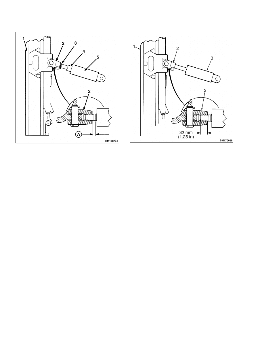
Check the tilt cylinder stroke by slowly tilting the
mast fully forward and backward several times. Both
tilt cylinders must stop their stroke at the same time.
Adjust the rod ends as shown in Figure 5. There
must be no twist in the mast weldments.
7
Tilt Cylinder Repair
2100 SRM 1139
A. DIMENSION A = 15 mm (0.60 in.)
1.
MAST
2.
ROD END
3.
SHIMS
4.
TILT LIMIT SPACER
5.
TILT CYLINDER
Figure 5. Tilt Cylinder Adjustments (All Models
Except J1.60-2.00XMT (J30-40ZT) (J160))
1.
Adjust the stroke of the tilt cylinders WITHOUT
tilt limit spacers as follows:
a. Adjust the rod ends to 15 mm (0.6 in.) for all
tilt cylinders shown in Figure 5 and 23 mm
(1.25 in.) for all tilt cylinders shown in Fig-
ure 6.
b. Slowly tilt the mast backward until one
cylinder rod stops.
On the opposite cylin-
der, loosen the capscrews on the rod end.
Measure the distance from the end of the
cylinder to the back end of the rod end. Use
a wrench and turn the cylinder rod IN until
the dimension starts to decrease, then stop.
Repeat this procedure until both cylinder
rods stop at the same position within 1 mm
(0.04 in.). After the adjustments are com-
plete, tighten the capscrews on the rod ends.
c.
Tilt the mast fully backward and measure
the tilt angle.
See the nameplate for tilt
angles. If necessary, adjust both rod ends
equally for the correct angle.
1.
MAST
2.
ROD END
3.
TILT CYLINDER
Figure 6. Tilt Cylinder Adjustments (Models
J1.60-2.00XMT (J30-40ZT) (J160) Only)
2.
Adjust the stroke of the tilt cylinders WITH tilt
limit spacers as follows:
a. Adjust the rod ends to 15 mm (0.6 in.) for all
tilt cylinders as shown in Figure 5.
b. Slowly tilt the mast forward until one cylin-
der rod stops.
On the opposite cylinder,
loosen the capscrews on the rod end. Use
a wrench and turn the cylinder rod IN as
necessary. Repeat this procedure until both
cylinder rods stop at the same position
within 1 mm (0.04 in.).
c.
Slowly tilt the mast backward until one rod
end just contacts the spacer. Add shims to
fill the gap at the opposite rod end until both
rod ends contact the spacers within 0.5 mm
(0.02 in.).
d. After the adjustments are complete, tighten
the capscrews on the rod ends.
e.
Tilt the mast fully backward and measure
the tilt angle. See the nameplate for tilt an-
gles. If necessary, add an equal number of
shims to both rods for the correct angle.
8

2100 SRM 1139
Tilt Cylinder Repair
TILT CYLINDER LEAK CHECK FOR
TWO-STAGE LFL, TWO-STAGE FFL, AND
THREE-STAGE FFL
WARNING
During the test procedures for the hydraulic
system, use chains to fasten the load to the car-
riage to prevent it from falling. Keep all people
away from the lift truck during the tests.
Do NOT try to find hydraulic leaks by putting
your hand on hydraulic components under
pressure.
Hydraulic oil can be injected into
the body by the pressure.
1.
Operate the hydraulic system. Put a capacity
load on the forks, and raise and lower the load
several times. Lower the load and tilt the mast
forward and backward several times. Check for
leaks.
2.
Raise the carriage and load 1 m (3 ft). If the car-
riage slowly lowers when the control valve is in
the neutral position, there are leaks in the hy-
draulic system. The maximum speed that the
carriage is allowed to lower is 50 mm (2 in.) per
10 minutes when the hydraulic oil is 30 C (86 F).
If the oil temperature is 70 C (158 F), the max-
imum speed the carriage can lower is 150 mm
(6 in.) per 10 minutes.
3.
Check the lift cylinders for internal leaks. Re-
move the load from the forks. Install a gate valve
in the supply line between the main control valve
and the mast. Put a capacity load on the forks
again. Raise the carriage 1 m (3 ft). Close the
gate valve. If the carriage or mast weldments
lower SLOWLY, the seals in the lift cylinders
have leaks.
4.
If the carriage does not move, open the gate valve
and check the movement again. If the carriage
lowers when the gate valve is open, check for
leaks in the hydraulic lines and fittings. If no
leaks are found, the main control valve can be
worn or damaged.
Remove the load from the
forks.
TILT CYLINDER LEAK CHECK FOR THE
FOUR-STAGE FULL FREE-LIFT
WARNING
Never allow anyone under a raised carriage.
Do not put any part of your body in or through
the lift mechanism unless all parts of the mast
are completely lowered and the engine is
STOPPED.
Do not try to find hydraulic leaks by putting
your hand on hydraulic components under
pressure.
Hydraulic oil can be injected into
the body by the pressure.
1.
Put a capacity load on the forks. Use a safety
chain to hold the load to the carriage. Raise the
load approximately 2.5 m (8 ft). Put the mast in
a vertical position.
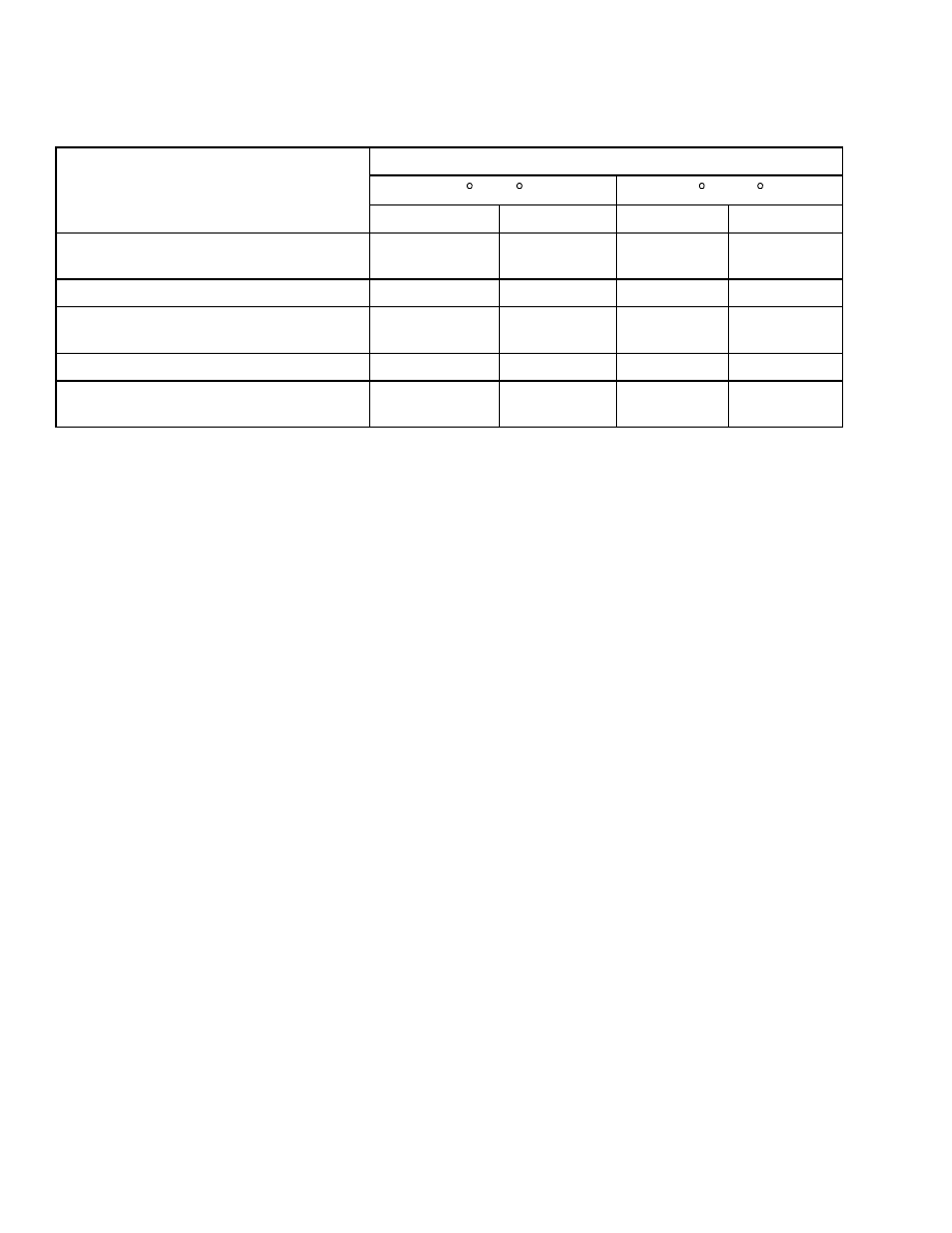
2.
Measure the distance that the rod for tilt cylin-
der extends from the shell. Check the distance
the rod moves in five or ten minutes. Multiply
the rate in Table 1 by the time of the test and
compare the numbers.
3.
If the tilt rate is greater than the specifications,
lower the mast and remove the load from the
forks. Install a valve between the port at the
front of the tilt cylinder and the hydraulic line.
The valve must be able to completely shut off the
flow of hydraulic oil. Put the load on the forks
again. Close the valve. Tilt the mast forward just
past the vertical position. If the mast continues
to tilt SLOWLY forward, the seals on the piston
are leaking.
4.
If the mast does not move, open the valve and
check the movement again. If the mast moves
forward when the gate valve is open, check for
leaks in the hydraulic lines and fittings. If no
leaks are found, the main control valve can be
worn or damaged.
Remove the load from the
forks when the checks are complete.
9
Tilt Cylinder Repair
2100 SRM 1139
Table 1. Movement Rates (Maximum) for Tilt Cylinders
Hydraulic Oil Temperature/Mast Tilt Rate
20 C (68 F)
60 C (140 F)
Lift Truck Model
mm/min
in./min
mm/min
in./min
S2.0-3.5FT
(S40-S70FT, S55FTS) (F187)
1.0
0.04
6.8
0.30
S30FT, S35FT, S40FTS (E010)
1.0
0.04
5.4
0.21
H1.6FT, H1.8FT, H2.0FTS (H30FT,
H35FT, H40FTS) (F001)
1.0
0.04
5.7
0.23
H2.0-3.5FT (H40-70FT) (L177)
1.0
0.04
6.3
0.25
E1.50-2.00XM (E25-35Z, E40ZS) (E114)
and J1.60-2.00XMT (J30-40ZT) (J160)
0.8
0.03
5.0
0.20
TORQUE SPECIFICATIONS
Piston Rod
S2.0-2.5FT (S40-S50FT, S55FTS) (F187),
S30FT, S35FT, S40FTS (E010), E1.50-2.00XM
(E25-35Z, E40ZS) (E114), H1.6FT, H1.8FT,
H2.0FTS (H30FT, H35FT, H40FTS) (F001),
and H2.0-2.5FT (H40-50FT) (L177)
170 to 220 N•m (125 to 163 lbf ft)
S3.0-3.5FT (S60-S70FT) (F187) and H3.0-3.5FT
(H60-70FT) (L177)
320 to 400 N•m (240 to 295 lbf ft)
J1.60-2.00XMT (J30-40ZT) (J160)
163 to 190 N•m (120 to 140 lbf ft)
Gland
S2.0-2.5FT (S40-S50FT, S55FTS) (F187) and
H2.0-2.5FT (H40-50FT) (L177)
170 to 237 N•m (125 to 175 lbf ft)
S3.0-3.5FT (S60-S70FT) (F187) and H3.0-3.5FT
(H60-70FT) (L177)
400 to 500 N•m (295 to 370 lbf ft)
S30FT, S35FT, S40FTS (E010), E1.50-2.00XM
(E25-35Z, E40ZS) (E114), J1.60-2.00XMT
(J30-40ZT) (J160), and H1.6FT, H1.8FT,
H2.0FTS (H30FT, H35FT, H40FTS) (F001)
163 to 190 N•m (120 to 140 lbf ft)
Tilt Cylinder Mounting Capscrew
38 N•m (28 lbf ft)
Tilt Cylinder Rod End Capscrew
90 N•m (66 lbf ft)
10

2100 SRM 1139
Lift Cylinder Repair
Lift Cylinder Repair
MAIN LIFT CYLINDERS, REMOVE
WARNING
Before working on or near the mast, see Safety
Procedures When Working Near Mast and Fig-
ure 1.
NOTE: The following procedures are for the removal
of the lift cylinders with the mast installed on the lift
truck.
1.
Remove the carriage as described in the carriage
removal procedures located in the section Mast
Repairs, 2, 3, and 4-Stage Masts 4000 SRM
1148. See Figure 1.
NOTE: Perform Step 2 if working on a lift truck
equipped with a two- or three-stage mast. Perform
Step 3 if working on a lift truck equipped with a
four-stage mast.
2.
Raise the mast until it is almost fully extended.
• On the two-stage mast, use safety chains to
connect the bottom crossmember of the inner
mast section to the top crossmember of the
outer mast section.
• On the three-stage mast, use safety chain to
connect the bottom crossmember of the inter-
mediate mast section to the top crossmember
of the outer mast section. Use another safety
chain to connect the bottom crossmember to
a crossmember on the intermediate or outer
mast section.
Lower the mast so the safety chains hold the
weight of the mast sections.
3.
Raise the mast until it is almost fully extended.
Use a safety chain to connect middle crossmem-
ber of first intermediate mast section to top cross-
member on outer mast section. Lower mast so
safety chain holds weight of the mast sections.
WARNING
Be careful when removing or installing snap
rings. These snap rings can come loose dur-
ing removal or installation with enough force
to cause an injury. Always use the correct snap
ring pliers, and wear eye and face protection
during removal or installation.
4.
If working on a two- or three-stage mast, remove
the snap ring or fitting at the top of the cylinder
to be removed.
If working on a four-stage mast, on left-hand lift
cylinder, remove the snap ring from top of the
cylinder rod. On right-hand lift cylinder, remove
spacer and retainer from cylinder rod.
WARNING
Hydraulic oil is hot after system operation and
can cause burns. Do not disconnect any hy-
draulic hoses until the oil in the system is cool.
6.
Put a drain pan under the area of the hydraulic
fittings.
Disconnect the hydraulic line at the
cylinder. Retract the rod into the lift cylinder.
7.
Remove the nut, bolt, and spacer at the mount.
On a two- or three-stage mast, disconnect the
main lift chain at the mount. See Figure 15.
8.
Use a lifting device, as necessary, to remove lift
cylinder from mast.
Remove the lift cylinder
from the front of the mast. On a lift cylinder be-
ing removed from a four-stage mast, keep shims
from top of left-hand cylinder with cylinder.
FREE-LIFT CYLINDER, REMOVE
1.
Remove the carriage as described in the car-
riage removal procedures in the section Mast
Repairs, 2, 3, and 4-Stage Masts 4000 SRM
1148. Lower the mast completely.
WARNING
Hydraulic oil is hot after system operation and
can cause burns. Do not disconnect any hy-
draulic hoses until the oil in the system is cool.
2.
Put a drain pan under the area of the hydraulic
fittings.
Disconnect the hydraulic line at the
cylinder.
NOTE: Perform Step 3 if working on a lift truck
equipped with a two- or three-stage mast. Perform
Step 4 if working on a lift truck equipped with a
four-stage mast.
3.
Remove the brackets for the free-lift cylinder. Re-
move the free-lift cylinder.
11
Lift Cylinder Repair
2100 SRM 1139
4.
Remove chains from chain sheaves. Remove the
clamp and brackets for the free-lift cylinder. Re-
move the free-lift cylinder.
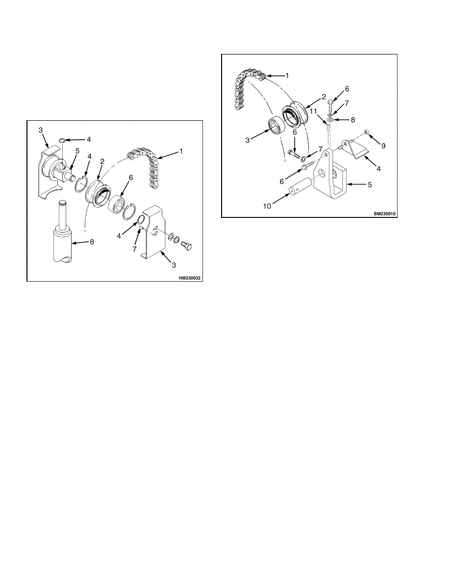
5.
Remove the crosshead from the cylinder rod. See
Figure 7, Figure 8, Figure 9, and Figure 10. Dis-
assemble the crosshead as necessary.
1.
LIFT CHAIN
2.
CHAIN SHEAVE
3.
CHAIN GUARD
4.
SNAP RING
5.
CROSSHEAD
6.
BEARING
7.
PIN
8.
FREE-LIFT
CYLINDER
Figure 7. Crosshead Assembly, Two-Stage and
Three-Stage FFL, Lift Truck Models S2.0-3.5FT
(S40-70FT, S55FTS) (F187) and H2.0-3.5FT
(H40-70FT) (L177)
1.
CHAIN
2.
CHAIN SHEAVE
3.
BEARING
4.
CHAIN GUARD
5.
CROSSHEAD
6.
CAPSCREW
7.
LOCKWASHER
8.
WASHER
9.
LOCK NUT
10. CROSSHEAD PIN
11. PIN
Figure 8. Crosshead Assembly, Two-Stage and
Three-Stage FFL, Lift Truck Models S30FT,
S35FT, S40FTS (E010), E1.50-2.00XM (E25-35Z,
E40ZS) (E114), J1.60-2.00XMT (J30-40ZT)
(J160), and H1.6FT, H1.8FT, H2.0FTS (H30FT,
H35FT, H40FTS) (F001)
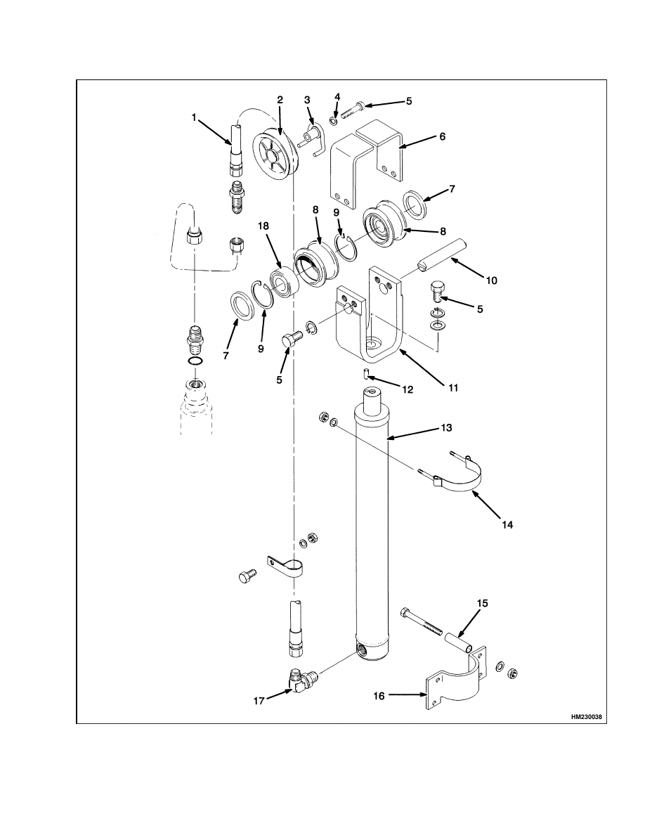
Legend for Figure 9
NOTE: LIFT TRUCK MODELS H2.0-3.5FT (H40-70FT) (L177) DO NOT HAVE A FOUR-STAGE MAST, BUT THE
CROSSHEAD AND TWO AND THREE-STAGE FREE-LIFT CYLINDER ASSEMBLY IS SIMILAR TO WHAT IS
SHOWN IN FIGURE 9.
1.
HOSE
2.
HOSE SHEAVE
3.
STUB SHAFT WELDMENT
4.
WASHER
5.
CAPSCREW
6.
CHAIN GUARD
7.
SPACER
8.
CHAIN SHEAVE
9.
SNAP RING
10. PIN
11. CROSSHEAD
12. ALIGNMENT PIN
13. FREE-LIFT CYLINDER
14. STRAP
15. TUBE SPACER
16. BRACKET
17. LOWERING CONTROL VALVE FITTING
18. BEARING
12
2100 SRM 1139
Lift Cylinder Repair
Figure 9. Crosshead and Four-Stage Free-Lift Cylinder Assembly, Lift Truck Models S2.0-3.5FT
(S40-70FT, S55FTS) (F187)
13
Lift Cylinder Repair
2100 SRM 1139
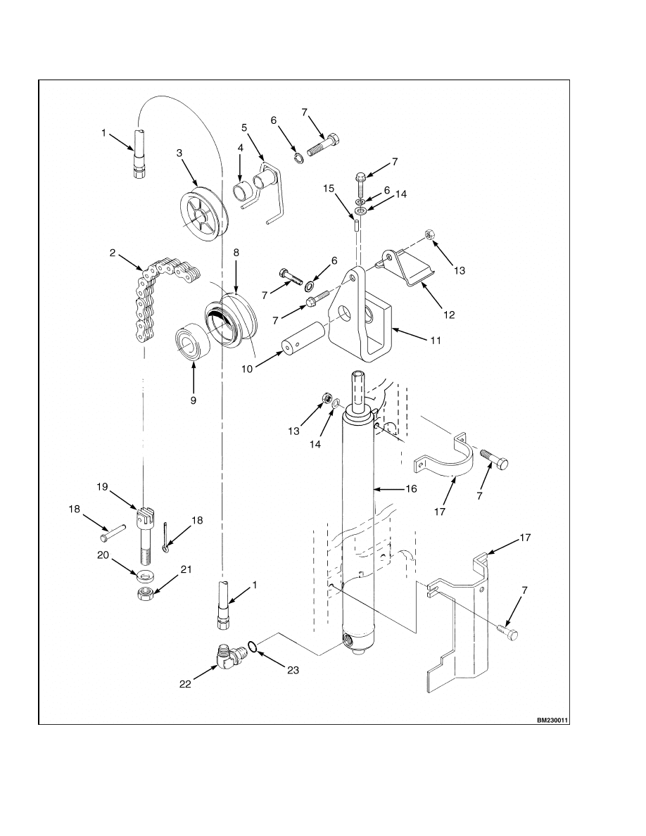
Figure 10. Crosshead and Three-Stage Free-Lift Cylinder Assembly, Lift Truck Models S30FT,
S35FT, S40FTS (E010), E1.50-2.00XM (E25-35Z, E40ZS) (E114), J1.60-2.00XMT (J30-40ZT) (J160),
and H1.6FT, H1.8FT, H2.0FTS (H30FT, H35FT, H40FTS) (F001)
14
2100 SRM 1139
Lift Cylinder Repair
Legend for Figure 10
1.
HOSE ASSEMBLY
2.
CHAIN
3.
HOSE SHEAVE
4.
BUSHING
5.
STUBSHAFT WELDMENT
6.
LOCKWASHER
7.
CAPSCREW
8.
CHAIN SHEAVE
9.
CHAIN SHEAVE BEARING
10. CROSSHEAD PIN
11. CROSSHEAD
12. CHAIN GUARD
13. LOCK NUT
14. WASHER
15. PIN
16. FREE-LIFT CYLINDER
17. BRACKET
18. COTTER PIN
19. CHAIN ANCHOR
20. HARDENED WASHER
21. NUT
22. FLOW VALVE
23. O-RING
FREE-LIFT AND MAIN LIFT CYLINDERS,
DISASSEMBLE
CAUTION
Carefully disassemble the lift cylinders so the
piston rods and sliding surfaces are not dam-
aged.
NOTE: To disassemble the left-hand main lift cylin-
der on trucks equipped with a two-stage FFL mast,
see the section Two-Stage FFL Cylinder, Disassem-
ble.
NOTE: To prevent damage to sealing surfaces, use
brass tools when removing or installing seals and
O-rings.
1.
Remove gland from shell.
2.
Remove rod and piston assembly from shell.
Drain hydraulic oil into container.
See Fig-
ure 11, Figure 12, and Figure 13.
3.
Remove and discard O-rings, seals, and wear
rings.
WARNING
Be careful when removing or installing snap
rings. These snap rings can come loose dur-
ing removal or installation with enough force
to cause an injury. Always use the correct snap
ring pliers and wear eye and face protection
during removal or installation.
4.
On left-hand lift cylinder, remove snap ring,
washer, and check valve from base of piston.
1.
SHELL
2.
ROD
3.
GLAND
4.
ROD SEAL
5.
CHECK VALVE
6.
WASHER
7.
O-RING
8.
SNAP RING
9.
WIPER RING
10. SEAL
11. BACKUP RING
12. WEAR RING
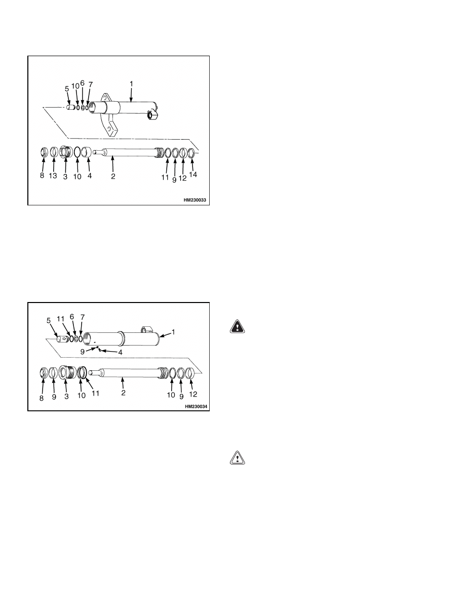
Figure 11. Main Lift Cylinder, Two-Stage LFL
15
Lift Cylinder Repair
2100 SRM 1139
1.
SHELL
2.
ROD
3.
GLAND
4.
SPACER
5.
CHECK VALVE
6.
WASHER
7.
SNAP RING
8.
WIPER RING
9.
SEAL
10. O-RING
11. BACKUP RING
12. WEAR RING
13. ROD SEAL
14. PISTON RING
Figure 12. Main Lift Cylinders, Three-Stage
Full Free-Lift
1.
SHELL
2.
ROD
3.
GLAND
4.
SCREW
5.
CHECK VALVE
6.
WASHER
7.
SNAP RING
8.
WIPER
9.
SEAL
10. BACKUP RING
11. O-RING
12. WEAR RING
Figure 13. Free-Lift Cylinder, Two-Stage and
Three-Stage FFL
TWO-STAGE FFL CYLINDER,
DISASSEMBLE
NOTE: The following procedure applies only to the
left-hand main lift cylinder of the lift trucks covered
in this manual. For disassembly procedures on the
right-hand main lift cylinder, see the section Free-
Lift and Main Lift Cylinders, Disassemble and Fig-
ure 14.
1.
Loosen the gland with a spanner wrench. See
Figure 14.
2.
Remove gland, rod, and piston assembly from
shell. Drain hydraulic oil into a container.
3.
Remove piston from rod. Remove gland from rod.
INSPECT
Inspect the gland for damage to the threads and the
seal surfaces. Replace the gland if damaged.
Inspect the piston for any damage to the seal surfaces
and replace if damaged.
Inspect the rod for damage to the rod surface and
ensure that the rod is not bent. Replace the rod if
found to be damaged.
Inspect the inner surface of the cylinder tube for
damage. If the tube is found to be damaged, replace
the cylinder.
CLEAN
WARNING
Cleaning solvents can be flammable and toxic
and can cause skin irritation.
When using
cleaning solvents, always follow the solvent
manufacturer’s recommended safety proce-
dures.
Compressed air can move particles so they
cause injury to the user or to other personnel.
Make sure the path of the compressed air is
away from all personnel. Wear protective gog-
gles or a face shield to prevent injury to the
eyes.
CAUTION
Do not allow cleaning solvent to come in con-
tact with rubber components, as it will damage
those components.
Clean all metal parts in solvent and dry with com-
pressed air.
16
2100 SRM 1139
Lift Cylinder Repair
A. RIGHT-HAND CYLINDER
B. LEFT-HAND CYLINDER
1.
SHELL
2.
ROD
3.
GLAND
4.
SPACER
5.
WIPER RING
6.
BACKUP RING
7.
O-RING
8.
WEAR RING
9.
ROD RING
10. SCREW
11. SEAL
12. PISTON RING
13. PISTON
Figure 14. Main Lift Cylinder, Right-Hand and Left-Hand Two-Stage FFL
17
Lift Cylinder Repair
2100 SRM 1139
FULL FREE-LIFT AND MAIN LIFT
CYLINDERS, ASSEMBLE
NOTE: The procedures in this section cover all masts
except for two-stage FFL masts. See the section Two-
Stage FFL and Main Lift Cylinders, Assemble for the
procedures.
NOTE: To prevent damage to sealing surfaces, use
brass tools when installing seals and O-rings.
1.
Lubricate all internal parts of the lift cylinder
with clean hydraulic oil or packing lubricant,
Hyster Part No. 186061. Use new O-rings, seals,
and wear rings. See Figure 13.
WARNING
Be careful when removing or installing snap
rings. These snap rings can come loose dur-
ing removal or installation with enough force
to cause an injury. Always use the correct snap
ring pliers and wear eye and face protection
during removal or installation.
2.
Install check valve and O-ring in base of pis-
ton of free-lift cylinder and left-hand lift cylinder.
Make sure arrow on check valve is toward base
of piston. Install washer and snap ring for check
valve. See Figure 13.
CAUTION
A difficult and important step in assembling
lift cylinders is the correct installation of the
seals. Most lift cylinder maintenance is caused
by seal leaks. Do not damage any parts during
assembly.
3.
Install the wear ring, piston seal, and backup
ring on to the piston assembly. On the main lift
cylinders, install seal ring. Install spacer, if used.
4.
Carefully push the piston and rod assembly into
the shell.
5.
Install the rod seal ring and wiper into the gland.
Install the O-ring and backup ring on the outside
of the retainer.
CAUTION
Additives may damage the hydraulic system.
Before using additives, contact your local Hys-
ter dealer.
NOTE: Hydraulic oil is poured into the free-lift cylin-
ders to act as a cushion during load lifting to prevent
damage to the cylinders.
6.
On free-lift cylinders, before installing gland,
pour 150 cc (5 oz) of hydraulic oil into the cylin-
der shell.
7.
Carefully install the gland on the piston rod.
8.
Carefully engage threads and tighten gland
in shell until tight.
Use the correct span-
ner.
Do NOT hit gland with a hammer and
driver. Tighten gland to 340 to 410 N•m (250 to
300 lbf ft).
9.
Install the lowering control valve in port at base
of left-hand, main control cylinder. See Figure 12
and Figure 13.
TWO-STAGE FFL AND MAIN LIFT
CYLINDERS, ASSEMBLE
NOTE: To prevent damage to sealing surfaces, use
brass tools when installing seals and O-rings.
1.
Install rod wiper and rod seal in retainer. Install
O-ring on outside of retainer. Install retainer on
rod.
2.
For the left-hand main cylinder, install gland
onto rod and install the piston. Tighten piston
to 170 to 200 N•m (125 to 150. lbf ft).
3.
Install O-ring and backup ring on piston for
right-hand cylinder. If a spacer is used, install it
on rod. Install piston in rod. Tighten piston to
170 to 200 N•m (125 to 150. lbf ft).
WARNING
Be careful when removing or installing snap
rings. These snap rings can come loose dur-
ing removal or installation with enough force
to cause an injury. Always use the correct snap
ring pliers and wear eye and face protection
during removal or installation.
4.
Install check valve and O-ring in base of piston
of free-lift cylinder. Make sure arrow on check
valve is toward base of piston.
5.
For the right-hand main cylinder, install washer
and snap ring for check valve. See Figure 13.
18

2100 SRM 1139
Lift Cylinder Repair
6.
Carefully engage threads and tighten gland
in shell until tight.
Use the correct span-
ner.
Do NOT hit gland with a hammer and
driver. Tighten gland to 475 to 540 N•m (350 to
400 lbf ft).
CAUTION
The correct screw and sealing washer must
be used in this location. The wrong parts will
cause leaks or damage the cylinder. See your
Hyster lift truck dealer for the correct parts.
CAUTION
Additives may damage the hydraulic system.
Before using additives, contact your local Hys-
ter dealer.
7.
Remove screw and sealing washer. Pour 150 cc
(5 oz) of hydraulic oil into the cylinder through
the hole. This oil provides a hydraulic cushion
when the cylinder reaches the top of its stroke.
See Figure 14.
Install the screw and sealing
washer and tighten to 6 N•m (53 lbf in).
8.
Install fitting at base of free-lift cylinder. This is
a special fitting that limits flow of the hydraulic
oil.
MAIN LIFT CYLINDERS, INSTALL
1.
Use a lifting device with a capacity of at least
1600 kg (3527 lb) to raise the mast until it is al-
most fully extended. Use safety chains to connect
the bottom crossmember of the inner mast weld-
ment (two-stage) or intermediate mast weldment
(three-stage) to the top crossmember of the outer
mast weldment. Lower the mast so the safety
chains hold the weight of the weldments. See
Figure 12, Figure 13, and Figure 15.
2.
Install the lift cylinder in the mount at the bot-
tom of the outer mast. Install the nut, bolt, and
spacer (11, Figure 15) at the mount for the lift
cylinder. Tighten nut to 53 N•m (39 lbf ft).
3.
Install shims at top of left-hand cylinder. Use
a lifting device to lower the inner mast weld-
ment (two-stage) or intermediate mast weldment
(three-stage) on to the lift cylinder. Install the
washers and snap ring at the top of the left-hand
lift cylinder. Install retainer, fittings, and tube
at the top of the right-hand lift cylinder. Tighten
nuts from retainer to 33 N•m (24 lbf ft). See Fig-
ure 12, Figure 13, and Figure 15 for the correct
adjustment of the lift cylinders.
4.
Connect the hydraulic line at the base of the lift
cylinder. Connect the hydraulic line at the top of
the left-hand main lift cylinder on the two-stage
and four-stage full free-lift masts. Connect hy-
draulic line at tube on right-hand lift cylinder.
5.
Install balance line between main lift cylinder.
6.
Connect the main lift chains as necessary and ad-
just them as specified in the section Mast Re-
pairs, 2, 3, and 4-Stage Masts 4000 SRM 1148.
7.
Remove the air from the cylinders on the two-
stage FFL as described below. See Figure 14.
a. Loosen the screws two turns to permit oil to
flow around the threads of the screw.
b. With the forks unloaded and the engine
speed at idle, raise the carriage using the hy-
draulic control. Raise the carriage 300 mm
(12 in.)
and then stop for ten seconds to
reduce the pressure in the cylinder. Repeat
this procedure until the oil flowing from
around the threads is free of air bubbles.
c.
Stop the carriage at the top of the cylinder
stroke. Tighten the screws.
19
Lift Cylinder Repair
2100 SRM 1139
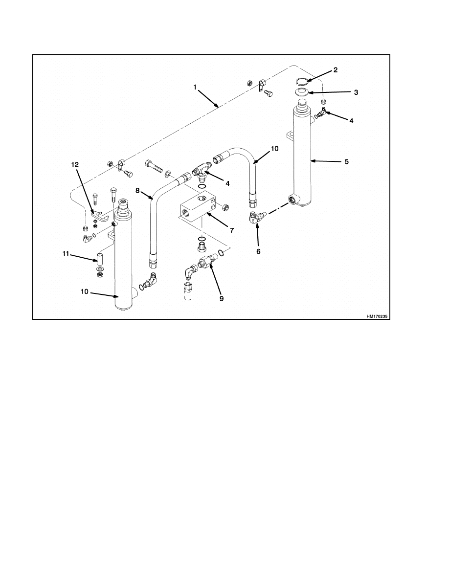
NOTE: BALANCE LINE IS USED ON FOUR-STAGE FFL MAST ONLY.
1.
BALANCE LINE
2.
SNAP RING
3.
SHIM
4.
FITTING AND O-RING
5.
LEFT-HAND MAIN LIFT CYLINDER
6.
LOWERING CONTROL VALVE FITTING
7.
HOUSING
8.
HOSE
9.
LOWERING CONTROL VALVE
10. RIGHT-HAND MAIN LIFT CYLINDER
11. SPACER
12. RETAINER
Figure 15. Main Lift Cylinders Installation
FREE-LIFT CYLINDER, INSTALL
1.
Make sure alignment pin is in position, then in-
stall the crosshead mount and crosshead assem-
bly on the cylinder rod. Tighten the capscrews for
the chain guards to 66 N•m (49 lbf ft). Tighten
the crosshead mount to 435 N•m (320 lbf ft).
Install chain sheaves in mount.
Install shaft
through sheaves. Install chain guard on mount,
making sure the shaft is in correct position. See
Figure 7 and Figure 13.
2.
Install the cylinder in the mounts. Install the
brackets, nuts, and tighten the bolts to 53 N•m
(39 lbf ft).
On the three-stage FFL cylinder,
the nuts are installed on the bracket side of the
free-lift cylinder. Tighten the nuts to 38 N•m
(28 lbf ft).
3.
Connect the hydraulic line at the cylinder.
4.
Install the carriage and load backrest as de-
scribed in the procedures for the section Mast
Repairs, 2, 3, and 4-Stage Masts 4000 SRM
1148.
20
2100 SRM 1139
Lift Cylinder Repair
TORQUE SPECIFICATIONS
Gland, Main Lift Cylinders
340 to 410 N•m (250 to 300 lbf ft)
Gland, Full Free-Lift Cylinders
475 to 540 N•m (350 to 400 lbf ft)
Piston, Main Lift Cylinders (Two-Stage
FFL Mast Only)
170 to 200 N•m (125 to 150 lbf ft)
Main Lift Cylinder Mounting Nut
To Outer Mast
53 N•m (39 lbf ft)
Retainer Nuts
33 N•m (24 lbf ft)
Chain Guard Capscrew (Free-Lift Cylinder)
66 N•m (49 lbf ft)
Crosshead Mount Capscrew
435 N•m (320 lbf ft)
Free-Lift Cylinder Mounting Bolts (All
Mast Except Three-Stage FFL)
53 N•m (39 lbf ft)
Free-Lift Cylinder Mounting Bolts
(Three-Stage FFL)
38 N•m (28 lbf ft)
LIFT CYLINDERS LEAK CHECK
WARNING
During the test procedures for the hydraulic
system, use chains to fasten the load to the car-
riage to prevent it from falling. Keep all people
away from the lift truck during the tests.
Do NOT try to find hydraulic leaks by putting
your hand on hydraulic components under
pressure.
Hydraulic oil can be injected into
the body by the pressure.
1.
Operate hydraulic system. Put capacity load on
forks. Use safety chain to hold load to carriage.
Raise and lower load several times. Lower load
and tilt mast forward and backward several
times. Check for leaks.
2.
Raise carriage and load 1 m (3 ft). If carriage
slowly lowers when control valve is in NEU-
TRAL position, there are leaks in hydraulic
system.
The maximum speed the carriage is
allowed to lower is 50 mm (2 in.) per 10 minutes
when hydraulic oil is 30 C (86 F). If oil tem-
perature is 70 C (158 F), the maximum speed
the carriage can lower is 150 mm (6 in.) per 10
minutes.
3.
Check lift cylinders for internal leaks. Remove
load from forks. Install valve in supply line be-
tween main control valve and mast. Put capacity
load on forks again. Raise carriage 1 m (3 ft).
Close valve. If carriage or mast lower slowly,
seals in lift cylinders have leaks.
4.
If carriage does not move, open valve and check
movement again. If carriage lowers when valve
is open, check for leaks in hydraulic lines and
fittings.
If no leaks are found, main control
valve can be worn or damaged.
Remove load
from forks.
21

NOTES
____________________________________________________________
____________________________________________________________
____________________________________________________________
____________________________________________________________
____________________________________________________________
____________________________________________________________
____________________________________________________________
____________________________________________________________
____________________________________________________________
____________________________________________________________
____________________________________________________________
____________________________________________________________
____________________________________________________________
____________________________________________________________
____________________________________________________________
____________________________________________________________
____________________________________________________________
____________________________________________________________
____________________________________________________________
____________________________________________________________
22


TECHNICAL PUBLICATIONS
2100 SRM 1139
9/05 (5/05)(12/04) Printed in United Kingdom
Document Outline
- toc
- Cylinder Repair
- Safety Precautions Maintenance and Repair
- General
- Description
- Safety Procedures When Working Near Mast
- Tilt Cylinder Repair
- Lift Cylinder Repair
- Main Lift Cylinders, Remove
- Free-Lift Cylinder, Remove
- Free-Lift and Main Lift Cylinders, Disassemble
- Two-Stage FFL Cylinder, Disassemble
- Inspect
- Clean
- Full Free-Lift and Main Lift Cylinders, Assemble
- Two-Stage FFL and Main Lift Cylinders, Assemble
- Main Lift Cylinders, Install
- Free-Lift Cylinder, Install
- Torque Specifications
- Lift Cylinders Leak Check
- tables
Wyszukiwarka
Podobne podstrony:
1580512 1600SRM1133 (05 2005) UK EN
1580518 2200SRM1130 (06 2005) UK EN
1495954 0900SRM0948 (09 2005) UK EN
1565653 2100SRM1116 (08 2005) UK EN
1580519 2200SRM1131 (07 2005) UK EN
1482638 8000SRM0805 (09 2005) UK EN
1510478 8000SRM0988 (06 2005) UK EN
1568204 0700SRM1159 (08 2005) UK EN
1566043 0620SRM1115 (08 2005) UK EN
897653 1800SRM0566 (04 2005) UK EN
więcej podobnych podstron