
USER INTERFACE
SUPERVISOR
S30FT, S35FT, S40FTS [E010];
H1.6FT, H1.8FT, H2.0FTS
(H30FT, H35FT, H40FTS) [F001];
S2.0-3.5FT (S40-70FT, S55FTS ) [F187];
H2.0-3.5FT (H40-70FT) [L177]
This manual contains information that is confidential and/or proprietary to Hyster
Company, its subsidiaries and/or vendors. Copying or distribution of any sections of
this manual marked "Confidential/Proprietary" is prohibited.
PART NO. 1580518
2200 SRM 1130

SAFETY PRECAUTIONS
MAINTENANCE AND REPAIR
• When lifting parts or assemblies, make sure all slings, chains, or cables are correctly
fastened, and that the load being lifted is balanced. Make sure the crane, cables, and
chains have the capacity to support the weight of the load.
• Do not lift heavy parts by hand, use a lifting mechanism.
• Wear safety glasses.
• DISCONNECT THE BATTERY CONNECTOR before doing any maintenance or repair
on electric lift trucks. Disconnect the battery ground cable on internal combustion lift
trucks.
• Always use correct blocks to prevent the unit from rolling or falling. See HOW TO PUT
THE LIFT TRUCK ON BLOCKS in the Operating Manual or the Periodic Mainte-
nance section.
• Keep the unit clean and the working area clean and orderly.
• Use the correct tools for the job.
• Keep the tools clean and in good condition.
• Always use HYSTER APPROVED parts when making repairs. Replacement parts
must meet or exceed the specifications of the original equipment manufacturer.
• Make sure all nuts, bolts, snap rings, and other fastening devices are removed before
using force to remove parts.
• Always fasten a DO NOT OPERATE tag to the controls of the unit when making repairs,
or if the unit needs repairs.
• Be sure to follow the WARNING and CAUTION notes in the instructions.
• Gasoline, Liquid Petroleum Gas (LPG), Compressed Natural Gas (CNG), and Diesel fuel
are flammable. Be sure to follow the necessary safety precautions when handling these
fuels and when working on these fuel systems.
• Batteries generate flammable gas when they are being charged. Keep fire and sparks
away from the area. Make sure the area is well ventilated.
NOTE: The following symbols and words indicate safety information in this
manual:
WARNING
Indicates a condition that can cause immediate death or injury!
CAUTION
Indicates a condition that can cause property damage!

User Interface
Table of Contents
TABLE OF CONTENTS
General ...............................................................................................................................................................
Description .....................................................................................................................................................
Dash Display Menu Access ...........................................................................................................................
Menu Navigation ...............................................................................................................................................
Standard Display ...........................................................................................................................................
Main Menu .........................................................................................................................................................
Passwords Menu ................................................................................................................................................
Password Administration ..................................................................................................................................
Add Password ................................................................................................................................................
Delete Password ............................................................................................................................................
Edit Password ................................................................................................................................................
Other Password Functions ................................................................................................................................
Operator Passwords - Enable/Disable ..........................................................................................................
Password Time-Out Delay.............................................................................................................................
Passwords - Number Wrong to Disable ........................................................................................................
Lockout Reset Password................................................................................................................................
View Password Log ........................................................................................................................................
Setup Display Menu ..........................................................................................................................................
Set Operator Language .................................................................................................................................
Set Units ........................................................................................................................................................
Set Time Format (12/24 Hour) ......................................................................................................................
Set Daylight Saving Time .............................................................................................................................
Set Time .........................................................................................................................................................
Set Date Format ............................................................................................................................................
Set Date..........................................................................................................................................................
Operator Checklist.............................................................................................................................................
Operator Checklist Off-On Mode ..................................................................................................................
Edit Operator Checklist ................................................................................................................................
Set Operator Checklist Expiration ...............................................................................................................
View Checklist Log ........................................................................................................................................
Clear Operator Checklist Log .......................................................................................................................
Clear Operator Checklist Fault ....................................................................................................................
This section is for the following models:
S30FT, S35FT, S40FTS [E010];
H1.6FT, H1.8FT, H2.0FTS (H30FT, H35FT, H40FTS) [F001];
S2.0-3.5FT (S40-70FT, S55FTS ) [F187];
H2.0-3.5FT (H40-70FT) [L177]
©2005 HYSTER COMPANY
i

"THE
QUALITY
KEEPERS"
HYSTER
APPROVED
PARTS
2200 SRM 1130
General
General
DESCRIPTION
NOTE: Initial setup of operator/supervisor pass-
words must be done by a qualified dealer technician
with service level menu access. Other truck func-
tions may be adjusted through the dash display
by a qualified dealer technician.
These functions
may include: Truck Speed Limit, Acceleration Rate,
Deceleration Rate, Power Reversal Rate, Inch/Brake
Overlap, Maximum Hydraulic Function Speeds,
Motion Alarm Operation, and Light Shutdown
Time-Out.
This section contains information to allow access to
the supervisor functions of the dash display. With a
proper supervisor password, the supervisor can ac-
cess menu items not visible to persons with operator
password level access. Supervisor level access is lim-
ited to all normal menu access areas described in the
Operator Manual for your lift truck and additional
areas in the Password Menu, Display Setup Menu,
Daily Checklist Menu, and the Impact Sensor Menu.
Menu items covering optional equipment will only be
displayed for those options installed on the lift truck.
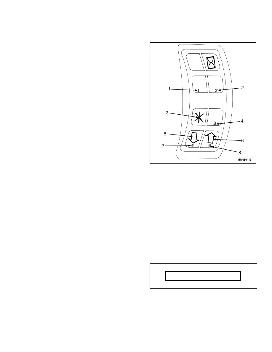
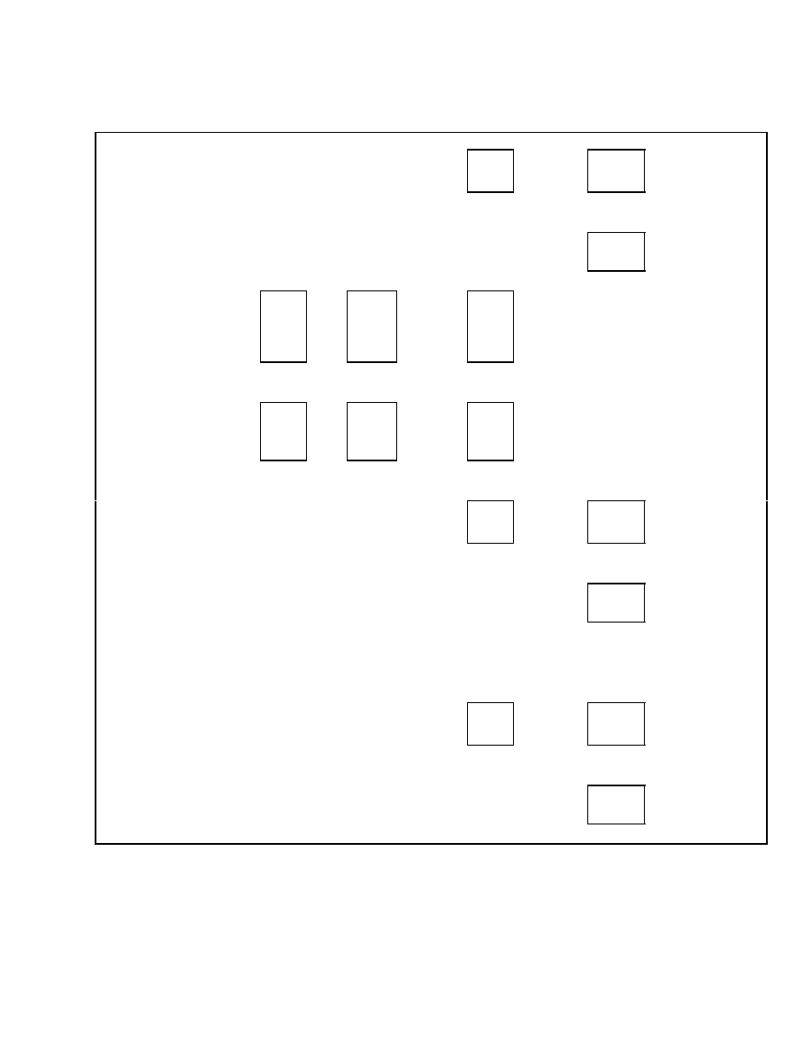
Access to display panel functions is through the scroll
keys #4 and #5 and the
*
key on the right-hand side
of the dash display located on the steering column of
the truck. See Figure 1. After successfully entering
your supervisor password into the dash display, push
the
*
key for access to the Main Menu.
DASH DISPLAY MENU ACCESS
NOTE: A qualified dealer technician with service
level access must install the initial supervisor
password. Once the initial supervisor password is
installed, that password may be used to access all
functions listed in this section and install additional
supervisor or password lockout passwords.
When the key is turned to the ON position or the
Power On button is pushed, the menu access keys are
activated.
1.
NUMERICAL PASSWORD ENTRY KEY #1
2.
NUMERICAL PASSWORD ENTRY KEY #2
3.
ENTER KEY
4.
NUMERICAL PASSWORD ENTRY KEY #3
5.
SCROLL DOWN KEY
6.
SCROLL UP KEY
7.
NUMERICAL PASSWORD ENTRY KEY #4
8.
NUMERICAL PASSWORD ENTRY KEY #5
Figure 1. Menu Access Keys
Upon initialization, the Password Screen will be
shown on the dash display. See Table 1. Enter your
five-digit supervisor password using the five number
keys on the right-hand dash display input panel.
Press the
*
key to enable all dash display menu
options allowed for supervisor password access.
Table 1. Password Screen
Enter Password XXXXX
Confidential/Proprietary - Do Not Copy or Duplicate
1

Passwords Menu
2200 SRM 1130
Menu Navigation
STANDARD DISPLAY
Upon successful entry of your supervisor password,
you will be directed to the Main Menu. Using the
scroll keys #4 and #5, scroll through the menu selec-
tions until you see the menu selection you want to
access. Press the
*
key to access that selection. The
Main Menu will only include the menus that are ac-
cessible with a supervisor password.
The
*
key allows you to move from menu to menu
and is used to make selections within a menu. The
#4 and #5 scroll keys allow you to move up and down
within a menu.
Each menu (except the Main Menu) will have a Back
One Level option within the menu options at that
level. Use the scroll keys #4 and #5 to access this
option. Press the
*
key to select this option and re-
turn to the previous menu.
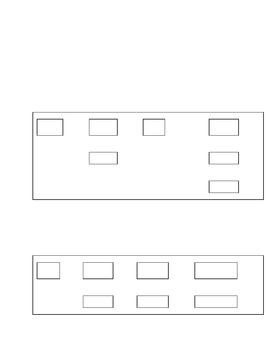
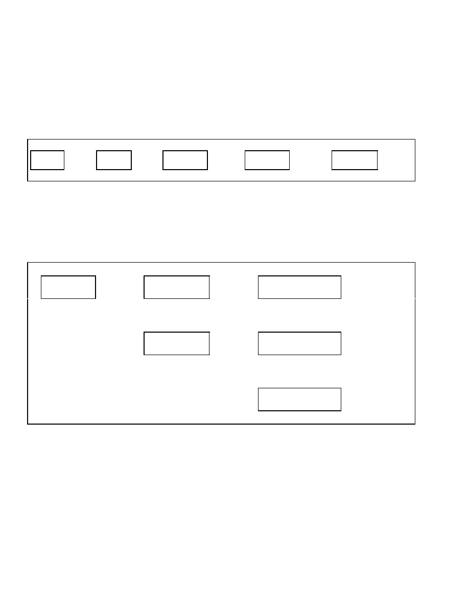
Any time an optional value is changed within a
menu, pressing the
*
key will take you to the Exit
Options menu where you will have the opportunity
to return to the previous menu, exit the menu system
without saving any changes, or save your changes
and exit the menu system. See Table 2.
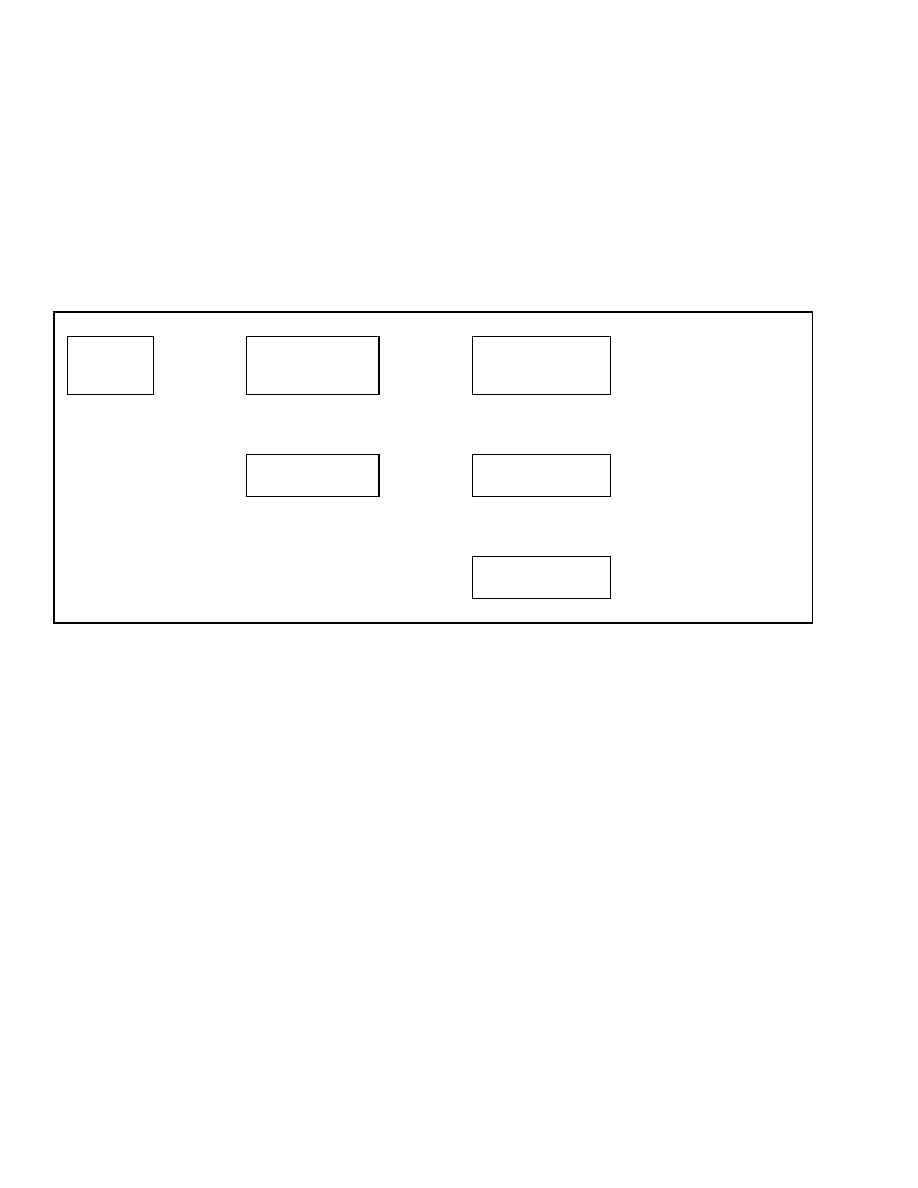
Table 2. Exit Options Menu
Main Menu
Save and Exit
Press
*
Key
Save All Changes and
Exit Menu - Yes
Press
*
Key to Save
Changes and Return to
Menu
↑
SCROLL
↓
↑
SCROLL
↓
Main Menu
Exit Without Saving
Cancel Save
Return to Menu
Press
*
Key to Exit and
Return to Menu
Main Menu
Upon entering the Main Menu from the password en-
try screen, the following menu functions are visible
to the supervisor:
• Passwords
• Setup Display
• Setup General Items
• Calibrations
Passwords Menu
Within the Passwords Menu, the supervisor has
access to the following additional dash display func-
tions: View Password Log, Add Password, Delete
Password,
Edit Password,
Operator Passwords
Enable/Disable, Password Time-Out Delay, and
Passwords – Number Wrong to Disable. These func-
tions are not available to anyone using an operator
password.
2
Confidential/Proprietary - Do Not Copy or Duplicate
2200 SRM 1130
Password Administration
Password Administration
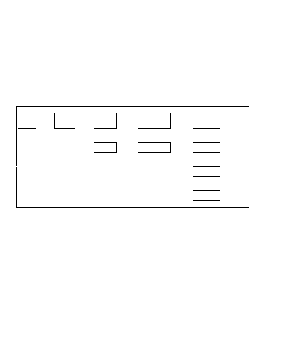
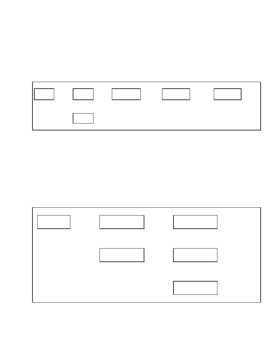
ADD PASSWORD
After entering the Add Password menu, enter the
new user’s five-digit password using the number
keys and press the
*
key to add the password. See
Table 3. You will be asked to enter the password
type.
Select:
Operator - Allows Truck Operation
Lockout Reset - Allows Person to Reset the Pass-
word Function After Password Lockout has Been
Enabled
Supervisor - Allows Access to the Above Functions,
All Password Menu Functions, and All Password
Entry Logs
If the password is accepted, the display will return to
the Add Password menu. Scroll to the Exit Options
menu and choose the appropriate action.
Table 3. Add Password Menu
Main Menu
Passwords
Press
*
Key
Passwords
Add Password
Press
*
Key
Enter
Password
Enter 5-Digit Password
and Press
*
Key
Password Type
Operator
Select 1
Operator
Type
↑
SCROLL
↓
↑
SCROLL
↓
Passwords
Back 1 Level
Password Type
Lockout Reset
↑
SCROLL
↓
Password Type
Supervisor
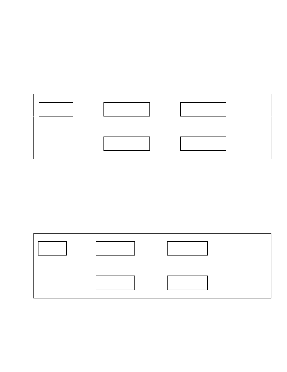
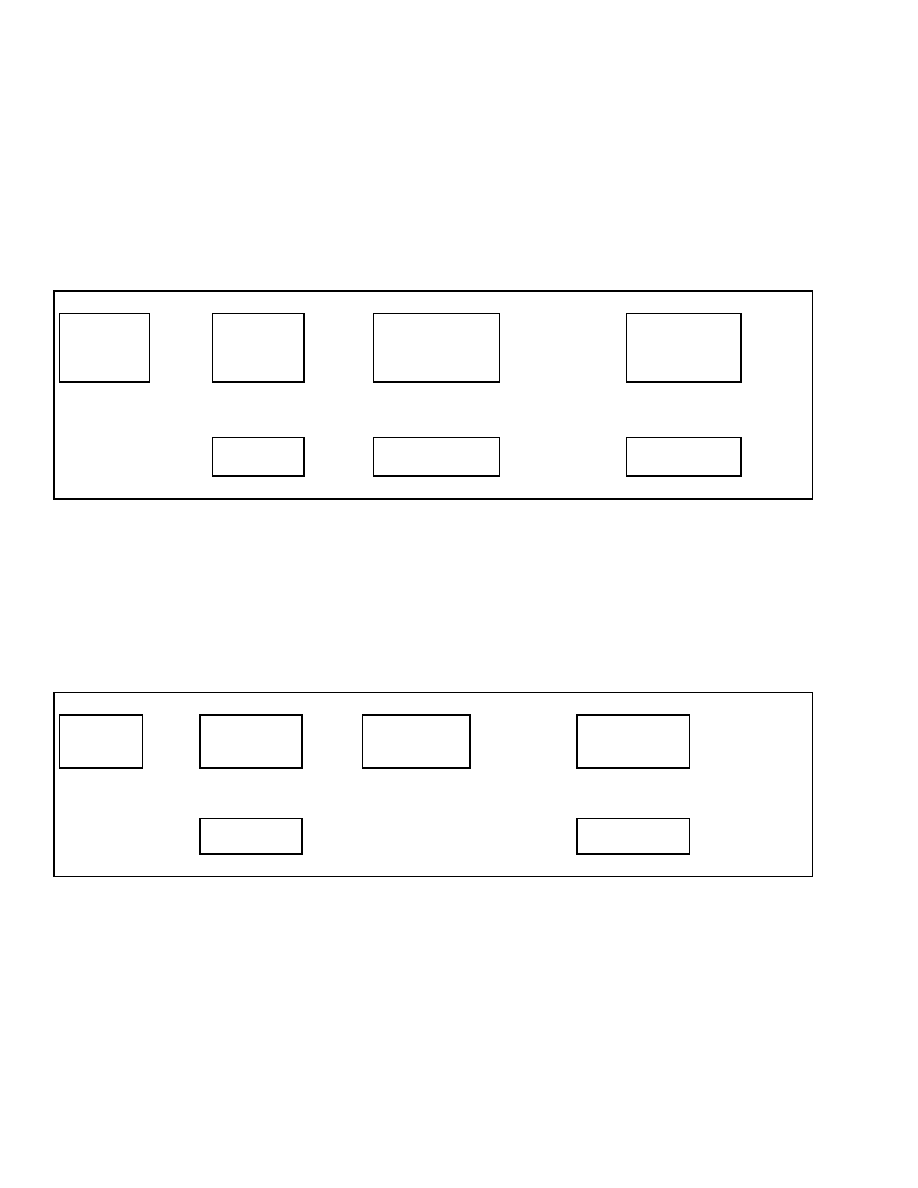
DELETE PASSWORD
This function allows the supervisor to delete the
password information of any user or supervisor.
After entering the Delete Password menu, enter the
five-digit password you want to delete and press the
*
key. See Table 4. You will be prompted to confirm
that you want to delete the password. If you want to
delete the password, choose Yes and press the
*
key.
If the delete is accepted, the display will return to the
Delete Password menu. Scroll to the Exit Options
menu and choose the appropriate action.
Table 4. Delete Password Menu
Main Menu
Passwords
Press
*
Key
Passwords
Delete Password Press
*
Key
Delete Password
Enter Password
Enter 5-Digit
Password and
Press
*
Key
Delete Password? No
Password XXXXX
Select Action
and
Press
*
Key
↑
SCROLL
↓
↑
SCROLL
↓
↑
SCROLL
↓
Passwords
Back 1 Level
Passwords
Back 1 Level
Delete Password? Yes
Password XXXXX
Confidential/Proprietary - Do Not Copy or Duplicate
3
Password Administration
2200 SRM 1130
EDIT PASSWORD
This function allows the supervisor to edit any exist-
ing password information that has been stored in the
dash display.
After entering the Edit Password menu, enter the
password you want to edit and press the
*
key.
If the password entered for editing has not been
stored in the dash display, the next higher stored
password will be displayed. Use the scroll keys to
scroll through the stored passwords.
Use the
*
key to select a password for editing. See Table 5.
The password and password type information for
the password entered will now be displayed on the
dash display. You can edit the five-digit password
by entering the new password using the number
keys. When finished, press the
*
key and edit the
password type.
Use the scroll keys to select the
new password type and press the
*
key to store the
selection.
Table 5. Edit Password Menu
Main Menu
Passwords
Press
*
Key
Passwords
Edit Password
Press
*
Key
Edit Password
Enter Password
Enter 5-Digit
Password and
Press
*
Key
Editing Password
Password XXXXX Type
Edit Password
and
Press
*
Key
Password Type
Operator
Select 1 Operator
Type and
Press
*
Key
↑
SCROLL
↓
↑
SCROLL
↓
↑
SCROLL
↓
Passwords
Back 1 Level
Passwords
Back 1 Level
Password Type
Lockout Reset
↑
SCROLL
↓
Password Type
Supervisor
↑
SCROLL
↓
Password Type
Service
If you want to continue making edits, select the Save
and Return option to return to the Edit Password
menu. If you are finished making changes, scroll to
the Exit Options menu and choose the appropriate
action.
4
Confidential/Proprietary - Do Not Copy or Duplicate
2200 SRM 1130
Other Password Functions
Other Password Functions
OPERATOR PASSWORDS -
ENABLE/DISABLE
If your lift truck is configured for optional operator
passwords, this function can be used to enable or dis-
able the use of operator passwords.
Use the scroll keys to select Activated or Deactivated
and press the
*
key to access the Exit Options menu
and choose the appropriate action. See Table 6.
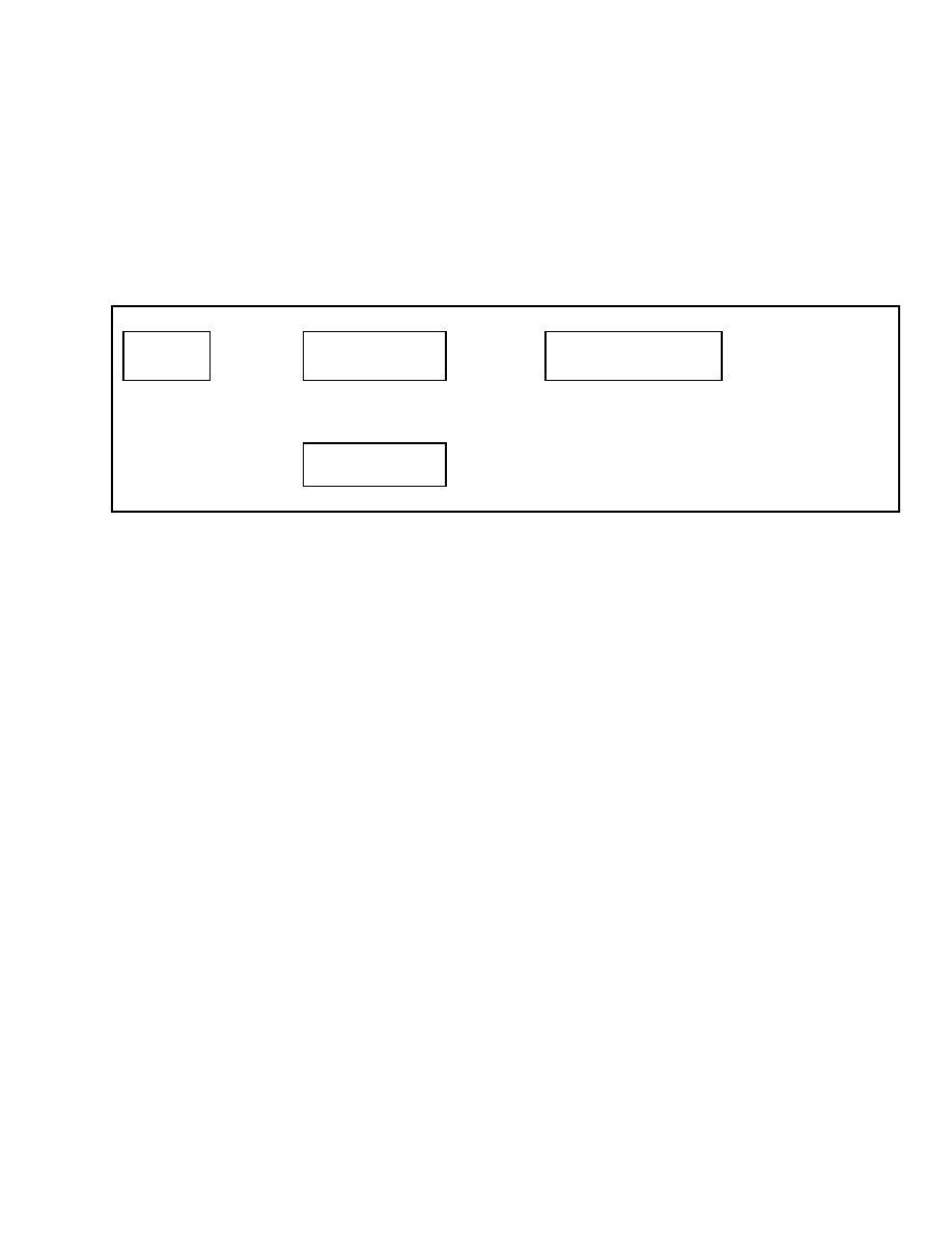
Table 6. Operator Passwords Menu
Main Menu
Passwords
Press
*
Key
Passwords
Operator Password
Press
*
Key
Operator Password
Activated
Select Action and
Press
*
Key
↑
SCROLL
↓
↑
SCROLL
↓
Passwords
Back 1 Level
Operator Password
Deactivated
PASSWORD TIME-OUT DELAY
If your lift truck is configured for optional operator
passwords, this function can be used to select the
amount of time an operator can turn OFF the lift
truck and RESTART the lift truck without having
to re-enter operator’s password.
After entering the Password Time-Out Delay menu,
enter the number of minutes you want to allow before
requiring re-entry of the operator password. See Ta-
ble 7. The delay must be entered in one-minute incre-
ments up to five minutes. For delay longer than five
minutes, the delay must be entered in five-minute in-
crements. The maximum delay that can be entered
is 30 minutes. After entering the delay, press the
*
key to access the Exit Options menu and choose the
appropriate action.
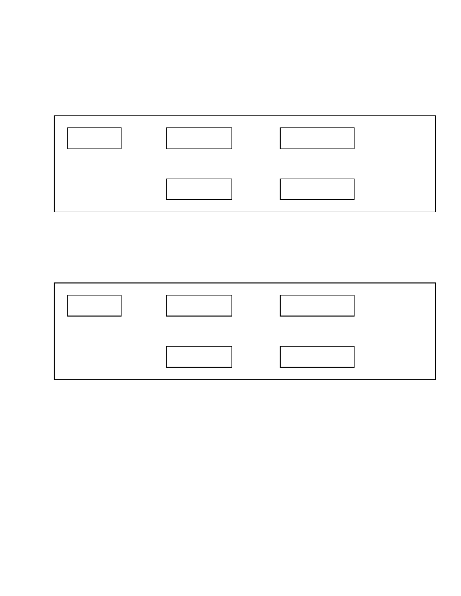
Table 7. Password Time-Out Delay Menu
Main Menu
Passwords
Press
*
Key
Passwords
Time-Out Delay
Press
*
Key
Time-Out Delay
30 Minutes
Select Delay from Available
Selections and Press
*
Key
↑
SCROLL
↓
↑
SCROLL
↓
Passwords
Back 1 Level
Time-Out Delay
0 Minutes
Confidential/Proprietary - Do Not Copy or Duplicate
5
Other Password Functions
2200 SRM 1130
PASSWORDS - NUMBER WRONG TO
DISABLE
This function is used to select the number of times
an operator can enter an incorrect password before
disabling further access to the lift truck.
After entering the Passwords – Number Wrong to
Disable menu, use the scroll keys to select between 1
and 10 attempts. See Table 8. You may also choose to
deactivate this function and allow unrestricted log-in
attempts. After making your selection, press the
*
key to access the Exit Options menu and choose the
appropriate action.
Table 8. Passwords - Number Wrong to Disable Menu
Main Menu
Passwords
Press
*
Key
Passwords
# Wrong To Disable
Press
*
Key
# Wrong To Disable
10 Entries
Select # of Wrong Entries
from Available Selections and
Press
*
Key
↑
SCROLL
↓
↑
SCROLL
↓
Passwords
Back 1 Level
# Wrong To Disable
1 Entries
↑
SCROLL
↓
# Wrong To Disable
Deactivated
LOCKOUT RESET PASSWORD
If the operator continues to enter an incorrect pass-
word and activates the lockout feature above, the sys-
tem must be reset by someone with a lockout reset
password, a supervisor password, or a service tech-
nician password. The supervisor can assign a lockout
reset password to anyone using the Passwords menu.
Enter the password using the Add Password menu
and select Lockout Reset for the password type. This
allows the person assigned the lockout reset pass-
word to unlock the lift truck without allowing access
to other dash display menu functions.
6
Confidential/Proprietary - Do Not Copy or Duplicate
2200 SRM 1130
Other Password Functions
VIEW PASSWORD LOG
Entering this function allows the supervisor to view
the log-in information of all users who have entered
a password into the dash display. See Table 9. This
provides the supervisor with the following informa-
tion – password, date, and the engine hourmeter
reading at the time of log-in each time a password
has been entered into the dash display. If the truck
has been accessed by a service technician, the log
will show a SERV entry.
The supervisor can scroll through the log entries us-
ing the scroll keys. Pressing the
*
key at any time
will return the display to the Passwords menu.
Table 9. View Password Log Menu
Main Menu
Passwords
Press
*
Key
Passwords
View Password Log
Press
*
Key
Password Log
06/12/04
XXXXX
998
Press
*
Key to Return
to Main Menu
↑
SCROLL
↓
Passwords
Back 1 Level
Confidential/Proprietary - Do Not Copy or Duplicate
7

Setup Display Menu
2200 SRM 1130
Setup Display Menu
SET OPERATOR LANGUAGE
This function allows the supervisor to select the lan-
guage to be used to display information on the dash
display.
NOTE: When changing languages, it may be nec-
essary for the dash display to reset to the new
language. This process may take several seconds
to complete. Wait for the dash display to reset and
display the new operator language.
Select the language desired by using the scroll keys.
See Table 10. After making your selection, press the
*
key to access the Exit Options menu and choose
the appropriate action.
Table 10. Set Language Menu
Main Menu
Setup Display
Press
*
Key
Setup Display
Set Oper Language
Press
*
Key
Set Oper Language
English
Select Language from
Available Options and
Press
*
Key
↑
SCROLL
↓
↑
SCROLL
↓
Setup Display
Back 1 Level
Set Oper Language
Spanish
↑
SCROLL
↓
Set Oper Language
Italian
↑
SCROLL
↓
Set Oper Language
German
↑
SCROLL
↓
Set Oper Language
French
↑
SCROLL
↓
Set Oper Language
Optional
8
Confidential/Proprietary - Do Not Copy or Duplicate
2200 SRM 1130
Setup Display Menu
SET UNITS
This function allows the supervisor to select the units
used to display information on the dash display.
Use the scroll keys to select between SI/Metric units
or Imperial/English units. See Table 11. After mak-
ing your selection, press the
*
key to access the Exit
Options menu and choose the appropriate action.
Table 11. Set Units Menu
Main Menu
Setup Display
Press
*
Key
Setup Display
Set Units (SI/Imp)
Press
*
Key
Set Units (SI/Imp)
Units - Imperial (Eng)
Select Units and
Press
*
Key
↑
SCROLL
↓
↑
SCROLL
↓
Setup Display
Back 1 Level
Set Units (SI/Imp)
Units - SI (Metric)
SET TIME FORMAT (12/24 HOUR)
This function allows the supervisor to select the for-
mat used by the dash display.
Using the scroll keys, select between a 12-hour for-
mat or a 24-hour format. See Table 12. After making
your selection, press the
*
key to access the Exit Op-
tions menu and choose the appropriate action.
Table 12. Set Time Format Menu
Main Menu
Setup Display
Press
*
Key
Setup Display
Set Time 12/24 Hr
Press
*
Key
Set Time 12/24 Hr
Set Time 12 Hr
Select Time Format and
Press
*
Key
↑
SCROLL
↓
↑
SCROLL
↓
Setup Display
Back 1 Level
Set Time 12/24 Hr
Set Time 24 Hr
Confidential/Proprietary - Do Not Copy or Duplicate
9
Setup Display Menu
2200 SRM 1130
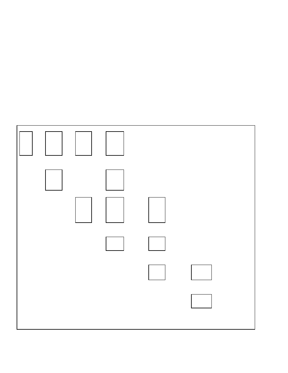
SET DAYLIGHT SAVING TIME
This function allows the supervisor to enable or dis-
able the use of daylight saving time on the dash dis-
play. When daylight saving time is enabled, the su-
pervisor can select the month and day daylight sav-
ing time will start and the month and day daylight
saving time will end.
To enable daylight saving time, select Daylight Save
On and press the
*
key.
Scroll to Daylight Save Start, press the
*
key, and
select the number of the month daylight saving time
is to start. See Table 13. Press the
*
key again, select
the day of the month daylight saving time is to start
and press the
*
key.
Scroll to Daylight Save End, press the
*
key and se-
lect the number of the month daylight saving time is
to end. Press the
*
key again, select the day of the
month daylight saving time is to end and press the
*
key to access the exit menu selections.
NOTE: You have the option of specifying either the
date or the day of the week to start or stop daylight
saving time. See the menu options.
Table 13. Set Daylight Saving Time Menu
Main
Menu
Setup
Display
Press
*
Key
Setup
Display
Set
Daylight
Saving
Press
*
Key
Set
Daylight
Saving
Daylight
Save
On/Off
Press
*
Key
Daylight
Save
On/Off
Daylight
Save On
Select On or
Off and
Press
*
Key
↑
SCROLL
↓
↑
SCROLL
↓
Setup
Display
Back One
Level
↑
SCROLL
↓
Daylight
Save
On/Off
Daylight
Save Off
Set
Daylight
Saving
Daylight
Save Start
Press
*
Key
Daylight
Save Start
Month 12
Select Daylight
Saving Start
Month from
Available
Selections and
Press
*
Key
Daylight
Save Start
Day 31
Select the Day
of the Month
from Available
Selections and
Press
*
Key
↑
SCROLL
↓
↑
SCROLL
↓
Daylight
Save Start
Month 01
Daylight
Save Start
Day 01
↑
SCROLL
↓
Daylight
Save Start
Day Last
Press
*
Key
Daylight Save
Start
Last Su
Select the Day of the Week
from Available Selections
and Press
*
Key
↑
SCROLL
↓
Daylight Save
Start
Last Sa
↑
SCROLL
↓
↑
SCROLL
↓
10
Confidential/Proprietary - Do Not Copy or Duplicate
2200 SRM 1130
Setup Display Menu
Table 13. Set Daylight Saving Time Menu (Continued)
Daylight
Save Start
Day 1st
Press
*
Key
Daylight Save
Start
1st Su
Select the Day of the Week
from Available Selections
and Press
*
Key
↑
SCROLL
↓
Daylight Save
Start
1st Sa
Set
Daylight
Saving
Daylight
Save End
Press
*
Key
Daylight
Save End
Month 12
Select Daylight
Saving End
Month from
Available
Selections and
Press
*
Key
Daylight
Save End
Day 31
Select the Day
of the Month
from Available
Selections and
Press
*
Key
↑
SCROLL
↓
↑
SCROLL
↓
↑
SCROLL
↓
Set
Daylight
Saving
Back One
Level
Daylight
Save End
Month 01
Daylight
Save End
Day 01
↑
SCROLL
↓
Daylight
Save End
Day Last
Press
*
Key
Daylight Save
End
Last Su
Select the Day of the Week
from Available Selections
and Press
*
Key
↑
SCROLL
↓
Daylight Save
End
Last Sa
↑
SCROLL
↓
Daylight
Save End
Day 1st
Press
*
Key
Daylight Save
End
1st Su
Select the Day of the Week
from Available Selections
and Press
*
Key
↑
SCROLL
↓
Daylight Save
End
1st Sa
Confidential/Proprietary - Do Not Copy or Duplicate
11
Setup Display Menu
2200 SRM 1130
SET TIME
This function allows the supervisor to set the time on
the on-board clock.
After entering the Set Time menu, a flashing cur-
sor will appear over the time segment that can be
changed. See Table 14. Move from segment to seg-
ment by pressing the
*
key. When finished, press the
*
key to access the Exit Options menu and choose the
appropriate action.
Table 14. Set Time Menu
Main Menu
Setup Display
Press
*
Key
Setup Display
Set Time
Press
*
Key
Set Time
Set Time XX:XX pm
Change Hours
and Press
*
Key
Set Time
Set Time XX:XX pm
Change Minutes
and Press
*
Key
Set Time
Set Time XX:XX pm
Change am/pm
and Press
*
Key
SET DATE FORMAT
This function allows the supervisor to select the for-
mat for displaying the date on the dash display.
After entering the Set Date Format menu, use the
scroll keys to select from the three options. See Ta-
ble 15. When finished, press the
*
key to access the
Exit Options menu and choose the appropriate ac-
tion.
Table 15. Set Date Format Menu
Main Menu
Setup Display
Press
*
Key
Setup Display
Set Date Format
Press
*
Key
Set Date Format
Set Date mm/dd/yyyy
Make Selection and
Press
*
Key
↑
SCROLL
↓
↑
SCROLL
↓
Setup Display
Back 1 Level
Set Date Format
Set Date dd/mm/yyyy
↑
SCROLL
↓
Set Date Format
Set Date yyyy/mm/dd
12
Confidential/Proprietary - Do Not Copy or Duplicate
2200 SRM 1130
Operator Checklist
SET DATE
This function is used to set the date used by the
on-board clock in the dash display.
After entering the Set Date menu, a flashing cur-
sor will appear over the date segment that can be
changed. See Table 16. Move from segment to seg-
ment using the
*
key. When finished, press the
*
key to access the Exit Options menu and choose the
appropriate action.
Table 16. Set Date Menu
Main Menu
Setup Display
Press
*
Key
Setup Display
Set Date
Press
*
Key
Set Date
Set Date 08/02/2004
Set Month and
Press
*
Key
Set Date
Set Date 08/02/2004
Set Day and
Press
*
Key
Set Date
Set Date 08/02/2004
Set Year and
Press
*
Key
↑
SCROLL
↓
Setup Display
Back 1 Level
Operator Checklist
OPERATOR CHECKLIST OFF-ON MODE
If your lift truck is configured for optional operator
checklist, this function can be used to enable or dis-
able the checklist.
Use the scroll keys to select On or Off. See Table 17.
There is also a selection that allows you to disable
the lift truck if there is a negative response to any
checklist item. After making your selection, press
the
*
key to access the Exit Options menu and choose
the appropriate action.
Table 17. Checklist Off-On Mode Menu
Main Menu
Setup Display
Press
*
Key
Setup Display
Checklist On/Off
Press
*
Key
Checklist On/Off
Checklist Off
Press
*
Key
↑
SCROLL
↓
↑
SCROLL
↓
Setup Display
Back 1 Level
Checklist On/Off
Checklist On
↑
SCROLL
↓
Checklist On/Off
Checklist On-Stop
Confidential/Proprietary - Do Not Copy or Duplicate
13
Operator Checklist
2200 SRM 1130
EDIT OPERATOR CHECKLIST
This function allows the supervisor to enable or dis-
able individual items included in the operator check-
list.
Use the scroll keys to select the checklist item and
press the
*
key. Use the scroll keys to select Activate
or Deactivate for the item you wish to change. See
Table 18. Press the
*
key again to save your selection
and return to the selection menu. If finished, press
the
*
key to access the Exit Options menu and choose
the appropriate action.
Table 18. Edit Checklist Menu
Main Menu
Setup Display
Press
*
Key
Setup Display
Edit Checklist
Press
*
Key
Edit Checklist
Forks & Carriage
Select Any Available
Checklist Item and
Press
*
Key
Operator Restraint
Item Deactivated
Make
Selection
and Press
*
Key
↑
SCROLL
↓
↑
SCROLL
↓
↑
SCROLL
↓
Setup Display
Back 1 Level
Edit Checklist
Operator Restraint
Operator Restraint
Item Activated
SET OPERATOR CHECKLIST EXPIRATION
If your lift truck is configured for optional operator
checklist, this function can be used to select how long
a completed operator checklist remains in effect and
whether it is to be measured using clock hours or
engine operating hours.
After entering the Set Operator Checklist Expiration
menu, enter the number of hours the truck can be
operated before requiring the operator to re-enter the
checklist data. See Table 19. Press the
*
key and
select between clock hours or engine hours. Press
the
*
key again to access the Exit Options menu and
choose the appropriate action.
Table 19. Checklist Expiration Menu
Main Menu
Setup Display
Press
*
Key
Setup Display
Checklist Expiration
Press
*
Key
Checklist Expiration
XX hr Clock
Set Hours for
Checklist to be Active
and Press
*
Key
Checklist Expiration
XX hr Clock
Select if Hours are Clock
Hours or Engine Hours
and Press
*
Key
↑
SCROLL
↓
↑
SCROLL
↓
Setup Display
Back 1 Level
Checklist Expiration
XX hr Engine
14
Confidential/Proprietary - Do Not Copy or Duplicate
2200 SRM 1130
Operator Checklist
VIEW CHECKLIST LOG
If your lift truck is configured for optional operator
checklist, the supervisor can use this function to view
the operator password, date, and engine hour read-
ing when a checklist was completed.
After entering the View Checklist Log menu, press
the
*
key to enter the log. See Table 20. The sys-
tem stores up to 20 checklist log entries. These en-
tries can be viewed by using the scroll keys to move
through each checklist entry. When finished viewing
the log, press the
*
key and return to the previous
menu. If you are finished making changes, scroll to
the Exit Options menu and choose the appropriate
action.
Table 20. View Checklist Log Menu
Main Menu
Setup Display
Press
*
Key
Setup Display
Checklist Log
Press
*
Key
Checklist Log XXXXX
06/12/04 engine hrs
Scroll to View Log
Entries and Press
*
Key When Finished
↑
SCROLL
↓
↑
SCROLL
↓
Setup Display
Back 1 Level
Checklist Log XXXXX
06/25/04 engine hrs
CLEAR OPERATOR CHECKLIST LOG
If your lift truck is configured for optional operator
checklist, the supervisor can use this function to
clear entries from the checklist failure log.
After entering the Clear Operator Checklist Log
menu, press the
*
key to select the Cleared option.
See Table 21. Press the
*
key again to clear the log
and return to the previous menu. If you are finished
making changes, scroll to the Exit Options menu
and choose the appropriate action.
Table 21. Clear Checklist Log Menu
Main Menu
Setup Display
Press
*
Key
Setup Display
Clear Checklist Log
Press
*
Key
Clear Checklist Log
Cleared
Press
*
Key to
Clear Log
↑
SCROLL
↓
Setup Display
Back 1 Level
Confidential/Proprietary - Do Not Copy or Duplicate
15
Operator Checklist
2200 SRM 1130
CLEAR OPERATOR CHECKLIST FAULT
If your lift truck is configured for optional operator
checklist, the supervisor can use this function to re-
turn a truck to service after the truck was disabled
by a negative response to an operator checklist item.
After entering the Clear Operator Checklist Fault
menu, press the
*
key. See Table 22. Press the
*
key again to clear the fault and return to the previ-
ous menu. If you are finished making changes, scroll
to the Exit Options menu and choose the appropriate
action.
Table 22. Clear Checklist Fault Menu
Main Menu
Setup Display
Press
*
Key
Setup Display
Clear Checklist Fail
Press
*
Key
Clear Checklist Fail
Cleared
Press
*
Key to
Clear Failure Log
↑
SCROLL
↓
Setup Display
Back 1 Level
16
Confidential/Proprietary - Do Not Copy or Duplicate


TECHNICAL PUBLICATIONS
2200 SRM 1130
6/05 (5/05)(12/04) Printed in United Kingdom
Document Outline
- toc
- tables
- Table 1. Password Screen
- Table 2. Exit Options Menu
- Table 3. Add Password Menu
- Table 4. Delete Password Menu
- Table 5. Edit Password Menu
- Table 6. Operator Passwords Menu
- Table 7. Password Time-Out Delay Menu
- Table 8. Passwords - Number Wrong to Disable Menu
- Table 9. View Password Log Menu
- Table 10. Set Language Menu
- Table 11. Set Units Menu
- Table 12. Set Time Format Menu
- Table 13. Set Daylight Saving Time Menu
- Table 14. Set Time Menu
- Table 15. Set Date Format Menu
- Table 16. Set Date Menu
- Table 17. Checklist Off-On Mode Menu
- Table 18. Edit Checklist Menu
- Table 19. Checklist Expiration Menu
- Table 20. View Checklist Log Menu
- Table 21. Clear Checklist Log Menu
- Table 22. Clear Checklist Fault Menu
Wyszukiwarka
Podobne podstrony:
1580519 2200SRM1131 (07 2005) UK EN
1510478 8000SRM0988 (06 2005) UK EN
1554634 2200SRM1078 (07 2005) UK EN
1586985 2200SRM1178 (03 2005) UK EN
1468474 2200SRM0756 (07 2005) UK EN
1466217 1900SRM0743 (06 2005) UK EN
1580512 1600SRM1133 (05 2005) UK EN
1580516 2100SRM1139 (09 2005) UK EN
897961 2200SRM0647 (03 2005) UK EN
1580521 2200SRM1143 (05 2005) UK EN
1595265 2200SRM1204 (01 2005) UK EN
1589731 2200SRM1184 (03 2005) UK EN
1463744 2200SRM0739 (04 2005) UK EN
897825 2200SRM0596 (03 2005) UK EN
1534735 2200SRM1056 (07 2005) UK EN
więcej podobnych podstron