ELECTRICAL SYSTEM
J1.6-2.0XMT (J30-40ZT) [J160]
PART NO. 1554634
2200 SRM 1078

SAFETY PRECAUTIONS
MAINTENANCE AND REPAIR
• When lifting parts or assemblies, make sure all slings, chains, or cables are correctly
fastened, and that the load being lifted is balanced. Make sure the crane, cables, and
chains have the capacity to support the weight of the load.
• Do not lift heavy parts by hand, use a lifting mechanism.
• Wear safety glasses.
• DISCONNECT THE BATTERY CONNECTOR before doing any maintenance or repair
on electric lift trucks. Disconnect the battery ground cable on internal combustion lift
trucks.
• Always use correct blocks to prevent the unit from rolling or falling. See HOW TO PUT
THE LIFT TRUCK ON BLOCKS in the Operating Manual or the Periodic Mainte-
nance section.
• Keep the unit clean and the working area clean and orderly.
• Use the correct tools for the job.
• Keep the tools clean and in good condition.
• Always use HYSTER APPROVED parts when making repairs. Replacement parts
must meet or exceed the specifications of the original equipment manufacturer.
• Make sure all nuts, bolts, snap rings, and other fastening devices are removed before
using force to remove parts.
• Always fasten a DO NOT OPERATE tag to the controls of the unit when making repairs,
or if the unit needs repairs.
• Be sure to follow the WARNING and CAUTION notes in the instructions.
• Gasoline, Liquid Petroleum Gas (LPG), Compressed Natural Gas (CNG), and Diesel fuel
are flammable. Be sure to follow the necessary safety precautions when handling these
fuels and when working on these fuel systems.
• Batteries generate flammable gas when they are being charged. Keep fire and sparks
away from the area. Make sure the area is well ventilated.
NOTE: The following symbols and words indicate safety information in this
manual:
WARNING
Indicates a condition that can cause immediate death or injury!
CAUTION
Indicates a condition that can cause property damage!

Electrical System
Table of Contents
TABLE OF CONTENTS
Introduction........................................................................................................................................................
General ...........................................................................................................................................................
Discharging the Capacitors...........................................................................................................................
Emissions .......................................................................................................................................................
Electromagnetic Interference ...................................................................................................................
Motor Controllers...............................................................................................................................................
Controllers .....................................................................................................................................................
Remove.......................................................................................................................................................
Install .........................................................................................................................................................
Hydraulics Contactor ....................................................................................................................................
Remove.......................................................................................................................................................
Disassemble ...............................................................................................................................................
Assemble ....................................................................................................................................................
Install .........................................................................................................................................................
Contactor Panel..................................................................................................................................................
Main Contactor ..............................................................................................................................................
Remove.......................................................................................................................................................
Disassemble ...............................................................................................................................................
Assemble ....................................................................................................................................................
Install .........................................................................................................................................................
Contactor Coil............................................................................................................................................
Contactor Tips ...........................................................................................................................................
Fuses ..............................................................................................................................................................
Display Units .....................................................................................................................................................
Features .........................................................................................................................................................
Replace ...........................................................................................................................................................
Key Switch..........................................................................................................................................................
Replace ...........................................................................................................................................................
Directional Controls...........................................................................................................................................
Directional Control Switches ........................................................................................................................
Accelerator Switches and Pedal Assembly...................................................................................................
Install .............................................................................................................................................................
Calibrate.........................................................................................................................................................
MONOTROL™ Directional Control .............................................................................................................
Brakes.................................................................................................................................................................
Brake Switch..................................................................................................................................................
Adjust or Replace ......................................................................................................................................
Master Cylinder Indicator.............................................................................................................................
Parking Brake Disengage .............................................................................................................................
Override Mode ...........................................................................................................................................
Horn Components and Steering Encoder .........................................................................................................
Horn Components ..........................................................................................................................................
Horn ...........................................................................................................................................................
Horn Button and Contacts........................................................................................................................
Steering Encoder ...........................................................................................................................................
Hood and Seat Switches ....................................................................................................................................
Hood Position Switches .................................................................................................................................
Seat Switch ....................................................................................................................................................
Steer Angle Potentiometer ................................................................................................................................
General ...........................................................................................................................................................
Operation .......................................................................................................................................................
©2005 HYSTER COMPANY
i

Table of Contents
Electrical System
TABLE OF CONTENTS (Continued)
Example .....................................................................................................................................................
Position Steer Tire for Straight Travel.........................................................................................................
Install .............................................................................................................................................................
Set Potentiometer to Midpoint .................................................................................................................
Install to Steer Axle ..................................................................................................................................
Calibrate ....................................................................................................................................................
Test .................................................................................................................................................................
Wiring Harness ..................................................................................................................................................
This section is for the following models:
J1.6-2.0XMT (J30-40ZT) [J160]
ii
2200 SRM 1078
Introduction
Introduction
GENERAL
This section includes removal, disassembly, checks,
adjustments,
assembly,
installation,
and trou-
bleshooting procedures for the electrical system
components on these models. Components covered
in other sections, such as motors and industrial
batteries, are not included in this section.
See the section AC Motor Controllers/Display
Panel, Description, Checks, Adjustments, and
Troubleshooting 2200 SRM 1087 for additional
information on the controller and for information on
troubleshooting fault codes, adjusting parameters,
and testing the controller.
See the section AC Motor Repair 620 SRM 1053 for
general information on AC motors.
See the section DC Motor Maintenance 620 SRM
294 for general information on DC motors.
See the section Industrial Battery 2240 SRM 1 for
information on battery maintenance.
See the section Electro-Hydraulic Control Valve
2000 SRM 1086 for information and service proce-
dures on the electro-hydraulic valve option and its
components.
See the section Periodic Maintenance 8000 SRM
1079 for regular maintenance schedules and proce-
dures.
See the section Diagrams 8000 SRM 1081 for the
wiring diagrams and schematics.
Throughout this section, forward will refer to travel
in the direction of the forks and left and right are
determined by an operator sitting in the seat facing
forward. See Figure 1.
DISCHARGING THE CAPACITORS
WARNING
Do not make repairs or adjustments unless you
are properly trained and authorized to do so.
Repairs and adjustments that are not correct
can create dangerous operating conditions.
Do not operate a lift truck that needs repairs.
Report the need for repairs to your supervisor
immediately. If repair is necessary, attach a
DO NOT OPERATE tag on the steering wheel.
Remove the key from the key switch.
WARNING
Disconnect the battery before opening the elec-
trical compartment cover or inspecting or re-
pairing the electrical system. If a tool causes
a short circuit, the high current flow from the
battery can cause personal injury or property
damage.
WARNING
Some checks and adjustments are done with
the battery connected.
Do not connect the
battery until the procedure tells you to do so.
Never have any metal on your fingers, arms,
or neck. Metal items can accidentally make an
electrical connection and cause injury.
WARNING
Block the lift truck to prevent unexpected
movement before performing any tests or ad-
justments.
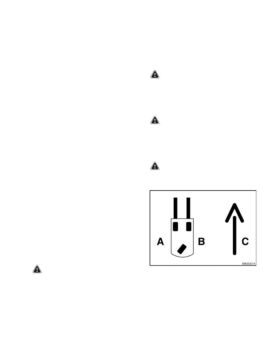
A. LEFT SIDE
B. RIGHT SIDE
C. FORWARD TRAVEL
Figure 1. Truck Orientation
1
Introduction
2200 SRM 1078
WARNING
The capacitor in the transistor controller(s)
can hold an electrical charge after the battery
is disconnected. To prevent an electrical shock
and personal injury, discharge the capacitor(s)
before inspecting or repairing any component
in the electrical compartment.
Wear safety
glasses.
Make certain that the battery has
been disconnected.
CAUTION
To avoid controller damage, always disconnect
the battery, discharge the capacitor(s), and
never put power to the controller while any
power wires are disconnected.
Never short
any controller terminal or motor terminal to
the battery. Make sure to use proper proce-
dure when servicing the controller.
1.
Turn key switch to OFF position and disconnect
the battery.
Block load wheels to prevent lift
truck from moving.
2.
Open the electrical compartment located at the
rear of the truck.
a. Remove the two screws securing the electri-
cal compartment door.
b. Tilt the door back on its hinges to open the
compartment.
NOTE: Some lift trucks are equipped with a premium
controller, which controls the hydraulic motor as well
as the traction motors.
3.
Discharge the capacitor in the controller by con-
necting a 200-ohm, 2-watt resistor across the
controller’s BT+ and B
terminals for 10 seconds
using insulated jumper wires. See Figure 2.
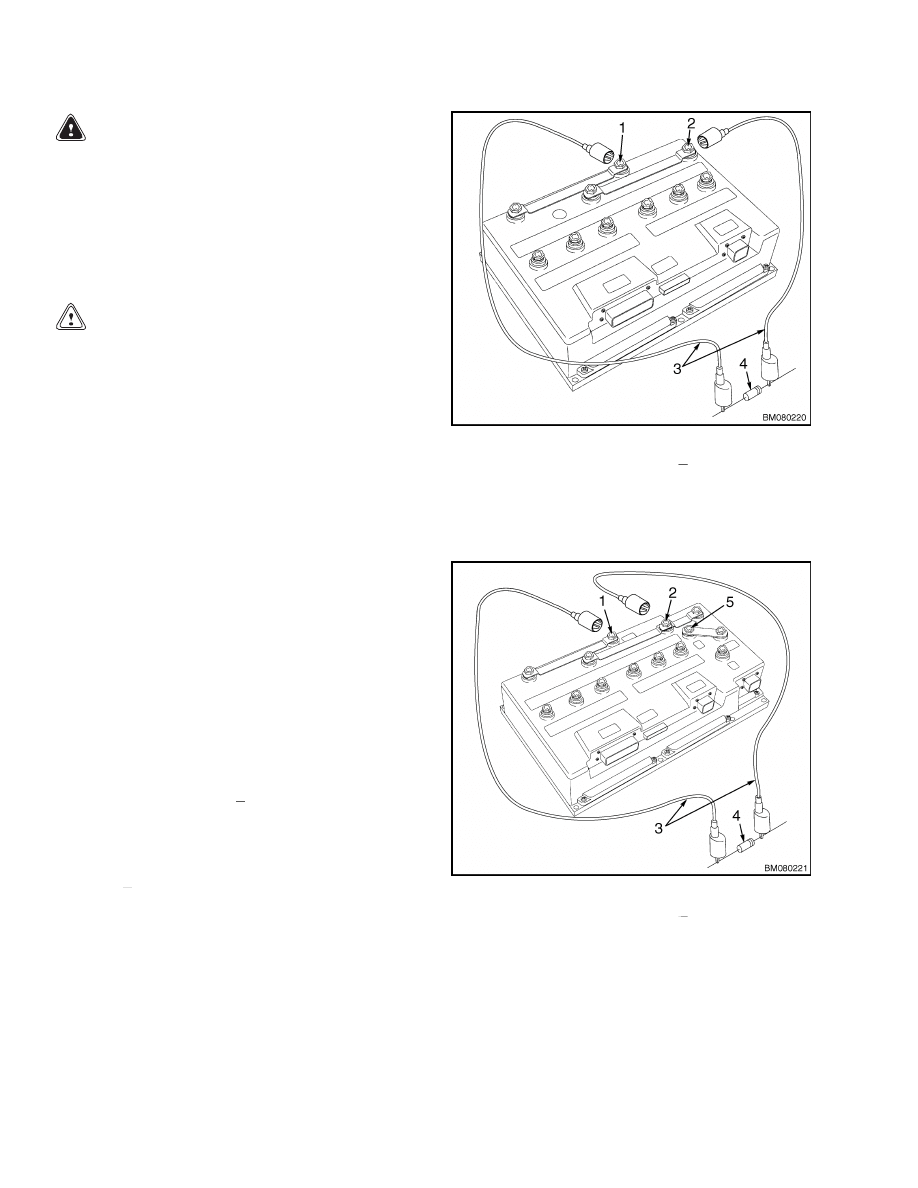
4.
On the premium controller, also connect the 200-
ohm, 2-watt resistor across the controller’s P+
and B
terminals for 10 seconds using insulated
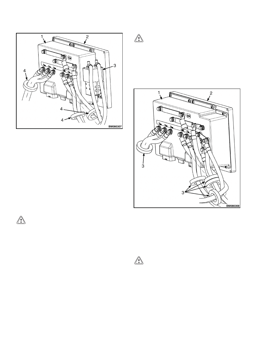
jumper wires. See Figure 3.
5.
Remove the 200-ohm, 2-watt resistor before re-
connecting the battery.
1.
POSITIVE CONNECTION (BT+)
2.
NEGATIVE CONNECTION (B )
3.
INSULATED JUMPER WIRES
4.
200-OHM, 2-WATT RESISTOR
Figure 2. Discharging the Capacitors
1.
POSITIVE CONNECTION (BT+)
2.
NEGATIVE CONNECTION (B )
3.
INSULATED JUMPER WIRES
4.
200-OHM, 2-WATT RESISTOR
5.
POSITIVE CONNECTION (P+)
Figure 3. Discharging the Capacitors
2
2200 SRM 1078
Motor Controllers
EMISSIONS
Electromagnetic Interference
Electromagnetic interference (EMI), also referred to
as radio-frequency interference (RFI), is the term
given to any unwanted electromagnetic disturbances
affecting the performance of useful electronic sig-
nals. The electrical system of the lift truck is capable
of producing EMI emissions during normal opera-
tion. Several EMI reduction devices are placed near
the transistor controller to reduce electromagnetic
emissions. These devices do not affect the perfor-
mance of the lift truck and help reduce disruptions
to communications devices, computers, and other
electronic devices.
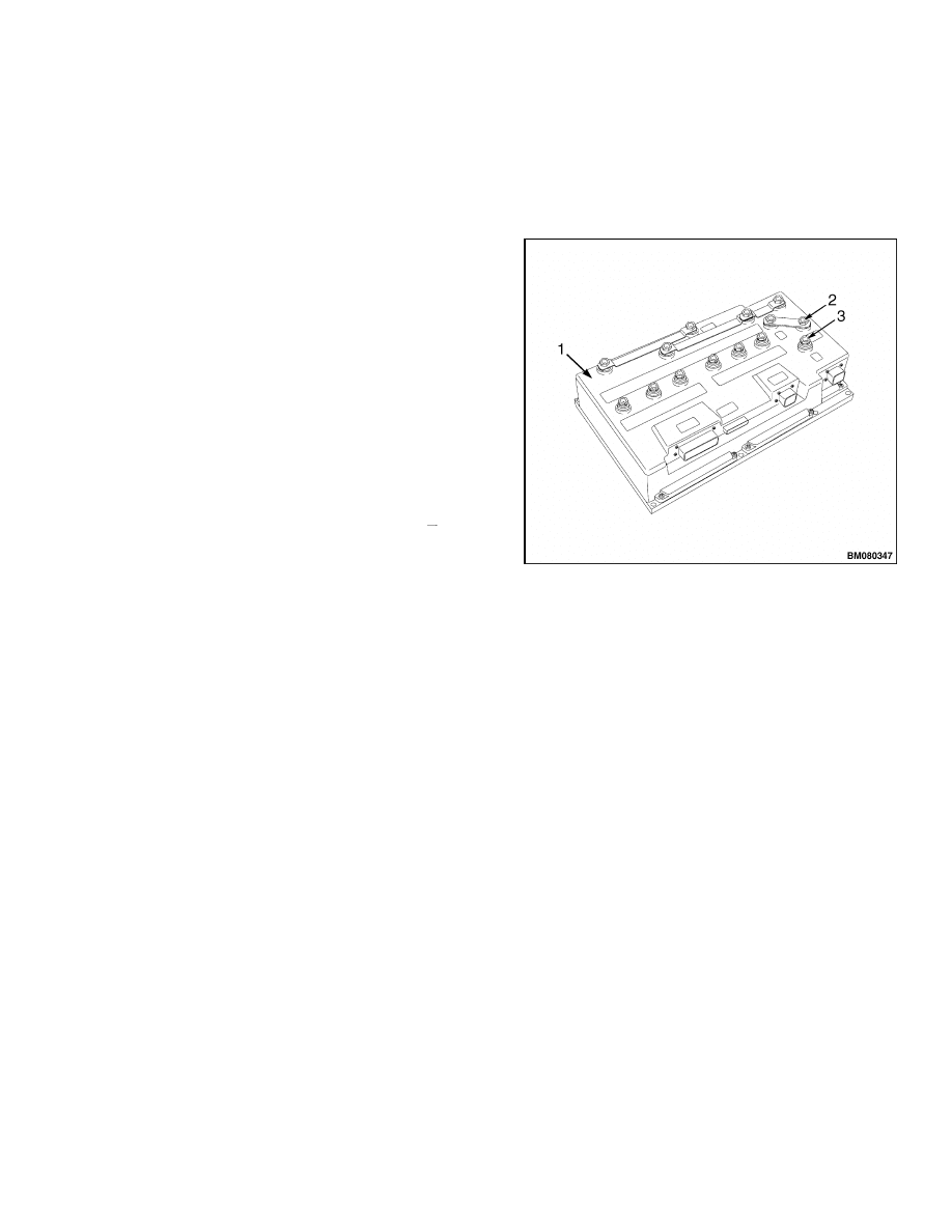
EMI reduction devices on these models include a ca-
pacitor on premium controllers and a series of fer-
rites installed standard on the transistor controller
power cables of all controllers. On models with tran-
sistor hydraulics (premium controller only), the ca-
pacitor is installed between the BPF+ and P
termi-
nals (see Figure 4) on the controller and functions
as an EMI reduction device. Ferrites are washer-
shaped, solid metallic components installed on the
power cables. Refer to Figure 5 or Figure 6. They
reduce EMI by blocking some of the emissions cre-
ated by the power cables. The capacitor (premium
controller only) reduces EMI by regulating spikes in
voltage. It stores surges of electricity and gradu-
ally releases the stored energy over a period of time.
These components are not serviced unless physically
damaged. Replace any damaged EMI reduction de-
vices immediately to maintain acceptable EMI emis-
sion levels.
1.
PREMIUM CONTROLLER
2.
CAPACITOR POSITIVE (BPF+)
3.
CAPACITOR NEGATIVE (P-)
Figure 4. Capacitor Placement
Motor Controllers
The motor controller assembly is mounted to the
inside of electrical compartment door.
The con-
troller is factory mounted to an aluminum heat sink.
The controller and heat sink assembly is mounted
against heat dispersal vanes in the electrical com-
partment door with socket-head screws. A thin layer
of thermal grease maximizes heat transfer between
the heat sink and the electrical compartment door.
The standard controller controls the power supply
and feedback from the traction motors. A contactor is
mounted beside the standard controller on the heat
sink, which controls current flow to the lift pump mo-
tor. The premium controller manages power for both
the traction motors and the lift pump motor; there is
no need for a lift motor contactor on this model.
CONTROLLERS
Remove
Certain repairs may not require the removal of all
components. Perform only the procedures necessary
to complete the repairs.
For the following proce-
dures, refer to Figure 5 or Figure 6.
1.
Turn the key switch to the OFF position and
disconnect the battery. Place blocks in front of
and behind the tires to prevent unexpected move-
ment.
3
Motor Controllers
2200 SRM 1078
1.
CONTROLLER
2.
HEAT SINK
3.
HYDRAULIC CONTACTOR
4.
FERRITES
Figure 5. Controller With Contactor Hydraulics
(Standard)
2.
Open the electrical compartment located at the
rear of the truck.
a. Remove the two screws securing the electri-
cal compartment door.
b. Tilt the door back on its hinges to open the
compartment.
CAUTION
Be sure to remove the resistor from the con-
troller before reconnecting the battery connec-
tor.
3.
Discharge the capacitors. See Discharging the
Capacitors in this section.
4.
Tag and disconnect the wiring and cables from
the controller and hydraulic contactor if so
equipped. It may be helpful to make a sketch
of the routing of the wiring and cables for assis-
tance during reassembly.
5.
Remove the hydraulic contactor (contactor hy-
draulic models), if necessary.
See Hydraulics
Contactor.
CAUTION
Do not remove the controller from the heat
sink plate. The controller is factory set and
mounted to the heat sink plate. ONLY remove
the controller and heat sink as an assembly.
6.
Remove the socket-head screws retaining the
controller and heat sink assembly to the electri-
cal compartment door.
1.
CONTROLLER
2.
HEAT SINK PLATE
3.
FERRITES
Figure 6. Controller With Transistor
Hydraulics (Premium)
Install
CAUTION
The back of the heat sink assembly, where the
assembly mounts to the electrical compart-
ment door, must be clean, free of paint and
rust, and completely covered with a thin, level
coat of electrical grease.
1.
Clean the back of the controller and heat sink
assembly thoroughly of paint, dirt, and rust.
4

2200 SRM 1078
Motor Controllers
2.
Apply an even coat of thermal compound (Hys-
ter™ 1198757 or equivalent) on the heat sink
plate of the motor controller. Position the mo-
tor controller assembly on to the mount surface
of the electrical compartment door. Make sure
there are no air spaces between the heat sink and
the mount surface. The heat sink must make full
contact with the mount surface. Secure the as-
sembly in place with socket head screws as re-
moved.
3.
Install the controller and heat sink assembly to
the electrical compartment door using screws as
removed.
4.
Install the hydraulic contactor (contactor hy-
draulic models), if removed.
See Hydraulics
Contactor.
5.
Connect cables and wiring to controller as re-
moved. Apply a light coat of dielectric grease to
each piece of the electrical connections during as-
sembly. Torque all cable connections to 13 N•m
(115 lbf in).
HYDRAULICS CONTACTOR
The hydraulic contactor is mounted on the heat sink
beside the standard controller. See Figure 5.
Remove
1.
Turn the key switch to the OFF position and
disconnect the battery. Place blocks in front of
and behind the tires to prevent unexpected move-
ment.
2.
Open the electrical compartment located at the
rear of the truck.
a. Remove the two screws securing the electri-
cal compartment door closed.
b. Tilt the door back on its hinges to open the
compartment.
CAUTION
Be sure to remove the resistor from the con-
troller before reconnecting the battery connec-
tor.
3.
Discharge the capacitors. See Discharging the
Capacitors in this section.
4.
Tag and disconnect the wiring and cables from
the contactor.
5.
Remove the screws securing the lift contactor to
the heat sink.
Disassemble
1.
Remove contactor from heat sink. See Remove.
2.
Remove screws that fasten the top cover to the
coil and frame.
3.
Remove cover, moving contact, and return
spring.
4.
Remove capscrews, washers, and nuts that make
up the fixed contactor tips from the top cover if
the contacts must be replaced. See Contactor
Tips in this section.
5.
If the coil will be replaced, remove coil frame and
remove end cap from frame. For information on
testing the contactor coil, see Contactor Coil in
this section.
Assemble
1.
Install new coil on frame and install end cap, if
removed.
2.
Install moving contact and return spring.
3.
Install capscrews, washers, and nuts, which
make up the fixed contactor tips, to the top
cover.
NOTE: Check that the moving contactor and springs
move freely without binding.
4.
Install cover to coil and frame using screws.
5.
Install contactor assembly onto heat sink. See
Install.
Install
1.
Install the lift contactor to the heat sink using
screws as removed.
2.
Connect cables and wiring to the lift contactor as
removed.
3.
Close the electrical compartment door and secure
using two screws.
4.
Remove blocks from wheels, connect the battery,
and test for proper operation.
5
Contactor Panel
2200 SRM 1078
Contactor Panel
WARNING
The capacitor in the transistor controller can
hold an electrical charge after the battery is
disconnected. Discharge the capacitor before
inspecting or repairing any component in the
electrical compartment to prevent personal in-
jury and damage to the electrical system. Al-
ways wear safety glasses.
See Discharging the Capacitors, in this section, for
information on how to properly discharge the capac-
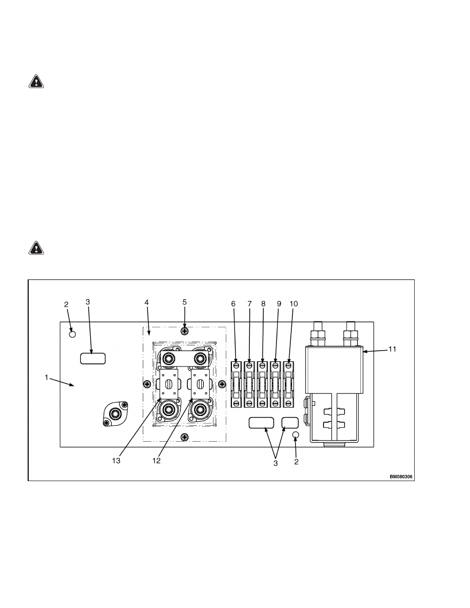
itors. The contactor panel is located in the electrical
compartment. See Figure 7.
MAIN CONTACTOR
Remove
WARNING
DO NOT short across the motor controller ter-
minals with a screwdriver or jumper wire.
1.
Turn the key switch to the OFF position and dis-
connect the battery.
2.
Open the electrical compartment located at the
rear of the truck.
a. Remove the two screws securing the electri-
cal compartment door closed.
b. Tilt the door back on its hinges to open the
compartment.
3.
Discharge the capacitors. See Discharging the
Capacitors.
4.
If the lift truck has an EE rating, remove cover
of the contactor box for access to the contactor
terminals.
5.
Tag and disconnect the wires and cables from the
contactor assembly.
1.
CONTACTOR PANEL
2.
MOUNTING HOLE
3.
LABELS
4.
ENCLOSURE (EE)
5.
SCREWS (EE)
6.
FUSE (FU11)
7.
FUSE (FU12)
8.
FUSE (FU13)
9.
FUSE (FU14)
10. FUSE (FU15)
11. MAIN CONTACTOR
12. FUSE (FU3)
13. FUSE (FU2)
(CONTACTOR HYDRAULICS)
Figure 7. Contactor Panel
6
2200 SRM 1078
Contactor Panel
6.
Remove two mounting screws securing contactor
assembly to the contactor panel and remove the
contactor assembly.
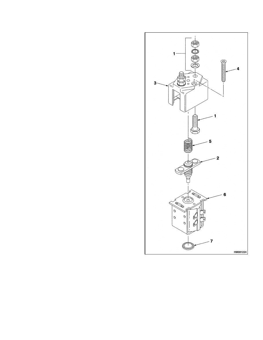
Disassemble
For the following procedures, refer to Figure 8.
1.
Remove contactor assembly from the contactor
panel. Refer to Remove.
2.
Remove screws (4) that fasten the top cover to the
coil and frame.
3.
Remove cover, moving contact (2), and return
spring.
4.
Remove capscrews, washers, and nuts that make
up the fixed contactor tips (1) from the top cover.
5.
If a coil will be replaced, remove coil frame and
remove end cap from frame.
6.
Remove coil from frame.
Assemble
For the following procedures, refer to Figure 8.
1.
Install new coil on frame and install end cap, if
removed.
2.
Install moving contact (2) and return spring.
3.
Install capscrews, washers, and nuts that make
up the fixed contactor tips (1) to the top cover.
NOTE: Check that the moving contactor and springs
move freely without binding.
4.
Install cover to coil and frame using screws (4).
Install
1.
Position contactor assembly in place and install
two mounting screws securing the contactor to
the contactor panel.
2.
Install wires and cables to the contactor assem-
bly as removed.
3.
Install cover of contactor box on EE units.
4.
Connect the battery, turn the key switch to the
ON position, and test for proper operation.
5.
Close the electrical compartment door and secure
using two screws.
1.
FIXED CONTACT
2.
MOVING CONTACT
3.
TOP COVER
4.
SCREW
5.
RETURN SPRING
6.
COIL AND FRAME
7.
END CAP
Figure 8. Main Contactor
7
Contactor Panel
2200 SRM 1078
Contactor Coil
Test the contactor coil.
Tag and disconnect coil wires. Check the coil using
an ohmmeter to measure the resistance. Record the
highest resistance indication. The coil should read 33
ohms ±10%. Replace coil with new one if resistance
readings are outside the specified range. Make sure
coil wires are connected to the proper terminals. See
Figure 8.
Contactor Tips
CAUTION
All contactor tips must be replaced at the same
time if any are replaced.
NOTE: If both the contactor tips and the coil will be
replaced, replace the entire contactor assembly as de-
scribed in Remove and Install.
The contactor tips are made of special silver alloy.
The contacts will look black and rough from normal
operation. This condition is normal and requires no
service. Cleaning is not necessary. DO NOT USE
A FILE ON THE CONTACTS. DO NOT LUBRI-
CATE THE CONTACTS. Replace contacts when
the silver alloy is worn away to the base support
metal.
Replace contactor tips at the same time.
Perform only the procedures necessary to complete
the repairs. See Figure 8.
FUSES
WARNING
DO NOT short across the motor controller ter-
minals with a screwdriver or jumper wire.
1.
Turn the key switch to the OFF position and dis-
connect the battery.
2.
Open the electrical compartment located at the
rear of the truck.
a. Remove the two screws securing the electri-
cal compartment door closed.
b. Tilt the door back on its hinges to open the
compartment.
3.
Discharge the capacitors. See Discharging the
Capacitors.
4.
Check the fuses. The condition of fuses can nor-
mally be checked visually, although some fuses
do not change in appearance and must be re-
moved and checked with an ohmmeter. Replace
all bad fuses. Check to determine the cause of
the fuse failure before replacing the fuse.
5.
Connect the battery and turn the key switch to
the ON position. Check for proper operation.
6.
Secure the rear compartment door closed.
Fuses
Circuit
Rating
FU-2
Hydraulic Motor
(Contactor Hydraulics)
500A
FU-3
Steer Motor
60A
FU-11
Light
10A
FU-12
Horn and Display
5A
FU-13
Valve Drivers and Lever
Controller
5A
FU-14
Motor Controllers
5A
FU-15
Auxiliary
20A
8
2200 SRM 1078
Display Units
Display Units
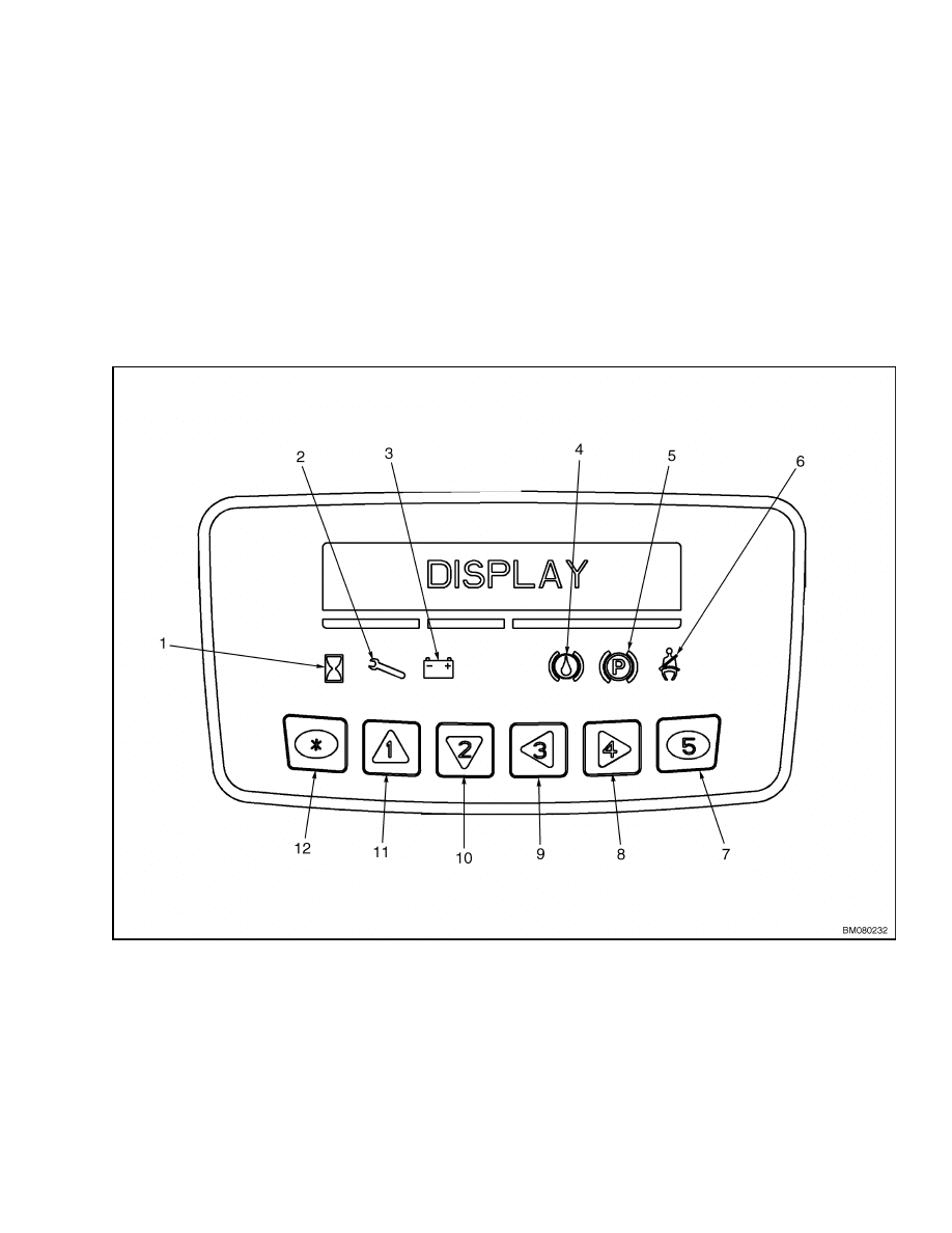
FEATURES
The following features are part of both the Standard
and Premium Display Units:
• LED (Light Emitting Diode) Symbol Indicators
• LCD (Liquid Crystal Display) Screen
• Hourmeter Indicator
• Service Indicator
• Battery Discharge Indicator
• Master Cylinder Indicator
• Parking Brake Indicator
• Seat Belt Indicator
These features are shown in Figure 9.
Since the
indicators are for common features, these indica-
tors are the same on the Premium Display Unit.
For more information on the standard and pre-
mium display units and their features, see AC
Motor Controllers/Display Panel, Description,
Checks,
Adjustments,
and Troubleshooting
2200 SRM 1087.
1.
HOURMETER
2.
SERVICE INDICATOR
3.
BATTERY INDICATOR
4.
MASTER CYLINDER INDICATOR
5.
PARKING BRAKE INDICATOR
6.
SEAT BELT INDICATOR
7.
BUTTON 5
8.
BUTTON 4
9.
BUTTON 3
10. BUTTON 2
11. BUTTON 1
12. STAR BUTTON
Figure 9. Standard and Premium Display Units
9
Display Units
2200 SRM 1078
REPLACE
WARNING
Before replacing the display, fully lower all
parts of the mast and tilt it forward until the
tips of the forks touch the ground. This action
will prevent the mast from lowering suddenly
if the control lever is accidentally moved.
Always disconnect the battery, remove the key,
and discharge the capacitor before replacing
the display.
Never have any metal on your finger, arms, or
neck. Metal items can accidentally make an
electrical connection and cause an injury.
CAUTION
A short circuit and damage can occur if wires
are not installed correctly. Make sure wire con-
nectors do not touch other power sources or
grounds. Make sure the wires are not pulled
tight or pinched. Route the wires to prevent
rubbing, chafing, or pinch points that can dam-
age the wires.
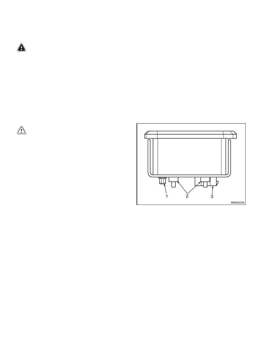
The display unit is located in the instrument panel
(dash) and has no serviceable parts. If malfunction-
ing, the unit must be replaced. See Figure 10.
1.
Lower the mast, turn the key switch to the OFF
position, and disconnect the battery.
2.
Disconnect the connectors from the bottom of the
display unit.
3.
Remove four finger nuts retaining the display
unit.
4.
Lift the display unit from the top of the instru-
ment panel (dash).
5.
Install the new display unit into the instrument
panel (dash) from the top.
6.
Secure display unit in place using four finger
nuts.
7.
Install the connectors to the bottom of the display
unit as removed.
8.
Connect the battery and turn the key switch to
the ON position.
9.
Test the display unit for proper operation before
returning the lift truck to service.
1.
CONNECTOR
2.
FINGER NUTS
3.
CONNECTOR
Figure 10. Display Unit Mounting
10
2200 SRM 1078
Key Switch
Key Switch
REPLACE
1.
Turn the key switch to the OFF position and re-
move the key. Disconnect the battery connector.
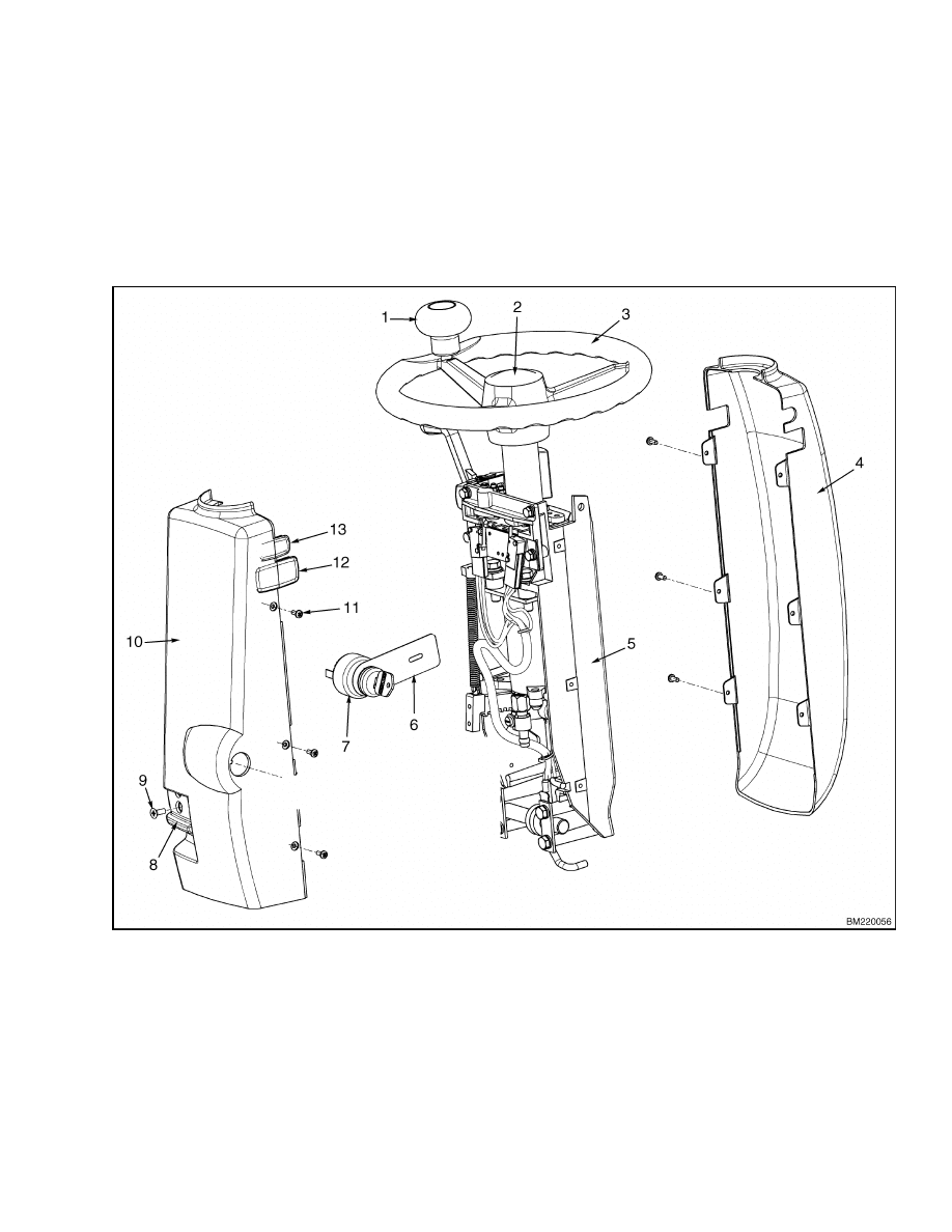
2.
Disassemble the steering column covers by re-
moving six screws securing the covers together
and two screws securing the latch release. Care-
fully separate the covers and collect all plugs.
See Figure 11.
3.
Tag and disconnect the wiring from the key
switch.
1.
STEERING KNOB
2.
HORN BUTTON
3.
STEERING WHEEL
4.
UPPER COVER
5.
COLUMN BRACKET
6.
STATIC GROUND STRAP
7.
KEY SWITCH
8.
LATCH RELEASE
9.
SCREW
10. LOWER COVER
11. SCREW
12. PLUG
13. PLUG
Figure 11. Key Switch Replacement
11
Directional Controls
2200 SRM 1078
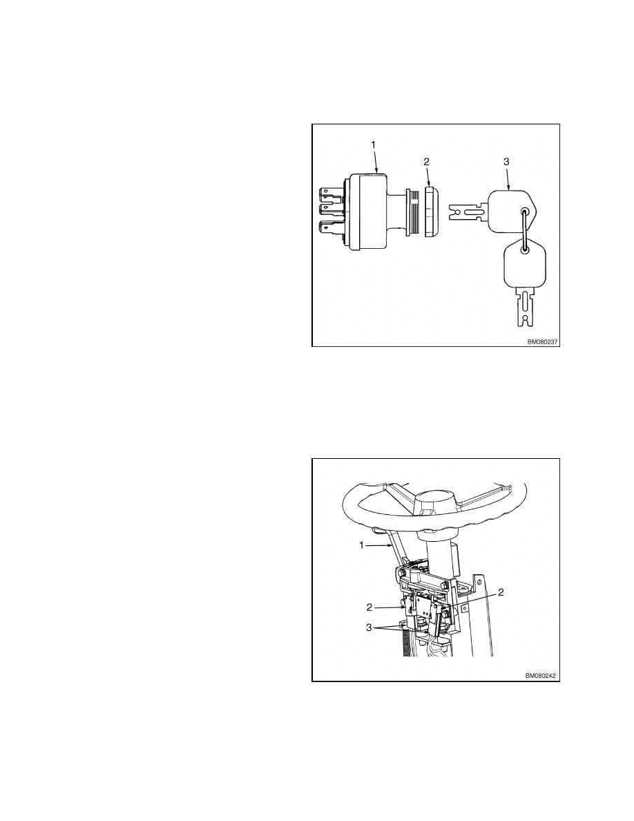
NOTE: Make a note of proper switch orientation for
reference during installation.
4.
Remove the key switch retaining nut from the
outside of the lower cover. See Figure 12.
5.
Remove the key switch from the lower cover and
remove the static ground strap from the switch.
6.
Install the static ground strap to the new key
switch and position the switch into the lower
cover.
NOTE: Make sure static ground strap is aligned with
screw hole in the cover.
7.
Install the key switch retaining nut to threads of
the key switch. Position switch and static ground
strap as removed and tighten retaining nut.
8.
Install wiring to the key switch as removed.
9.
Install the covers by assembling each half around
the steering column and installing six screws.
10. Install latch release and secure using two screws.
11. Connect the battery connector, insert the key into
the key switch, and turn to the ON position. Test
for proper operation.
1.
KEY SWITCH
2.
RETAINING NUT
3.
KEY
Figure 12. Key Switch
Directional Controls
DIRECTIONAL CONTROL SWITCHES
The directional control lever is mounted on the left
hand side of the steering column.
This lever is
attached to linkages, which activate the directional
control switches located inside the steering column.
These switches are responsible for communicating
to the controller which direction to turn the traction
motor.
See Figure 13 for the following procedures.
1.
Turn the key switch to the OFF position and dis-
connect the battery. Place blocks in front and be-
hind the drive tires to prevent unexpected move-
ment.
2.
Remove the steering column covers. See Steer-
ing System 1600 SRM 1075, Remove.
3.
Tag and disconnect wiring from switches.
4.
Remove the screws securing the directional con-
trol switches to the switch plate.
1.
DIRECTIONAL CONTROL LEVER
2.
DIRECTIONAL CONTROL SWITCHES
3.
CONNECTORS
Figure 13. Directional Control Switches
12

2200 SRM 1078
Directional Controls
CAUTION
DO NOT overtighten screws securing direc-
tional control switches to the switch plate.
5.
Install new switches and adjust so switch opens
and closes properly with movement of the direc-
tional control lever.
6.
Install wiring to switches as removed.
7.
Install the steering column covers and secure us-
ing six screws as removed. See Steering Sys-
tem 1600 SRM 1075, Install.
8.
Check for proper operation before returning to
service.
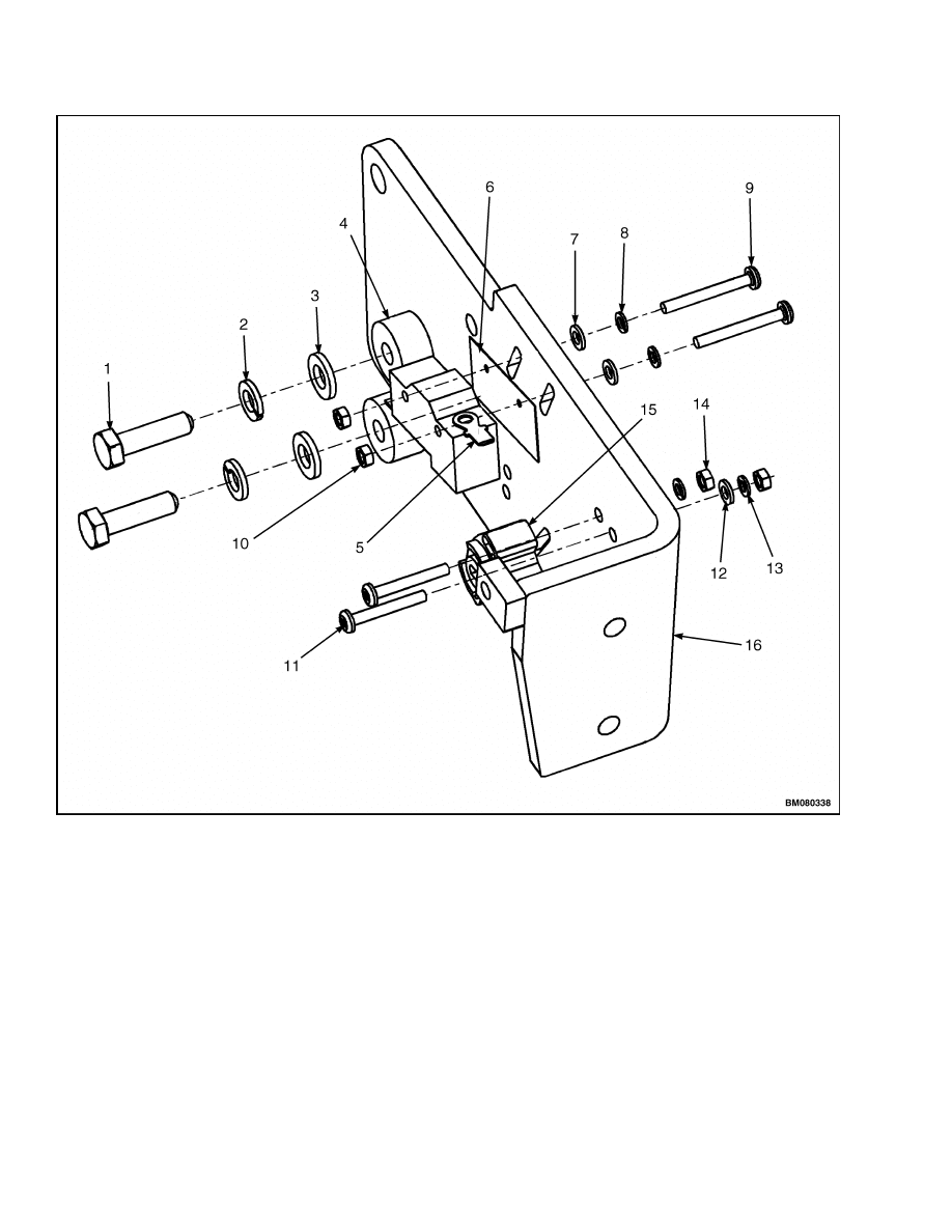
ACCELERATOR SWITCHES AND PEDAL
ASSEMBLY
The accelerator pedal is used to control the speed and
acceleration of the traction motors. The pedal is foot
controlled and is spring returned to its up position.
A neutral switch mounted on the mounting bracket
monitors when the pedal is in the neutral position.
When the pedal is depressed, a throttle position sen-
sor (potentiometer), mounted on the bracket below
the neutral switch, communicates the position of the
pedal to the controller. The controller then signals
the traction motors to accelerate accordingly.
INSTALL
WARNING
Installing and adjusting the throttle position
sensor can cause the lift truck to move unex-
pectedly. DO NOT attempt to install the sen-
sor until the drive tires have been suspended
above the floor.
1.
Turn the key switch to the OFF position and dis-
connect the battery.
2.
Position the lift truck on blocks so that the drive
tires are suspended above the floor.
3.
Mount neutral switch with isolator pad to the ac-
celerator bracket loosely using two screws, lock-
washers, washers, and nuts. See Figure 14.
NOTE: This application requires the neutral switch
to be wired normally closed (NC). Connect wiring to
the normally closed terminal (NC) and the neutral
terminal on the neutral switch.
4.
Connect wiring to the neutral switch as removed.
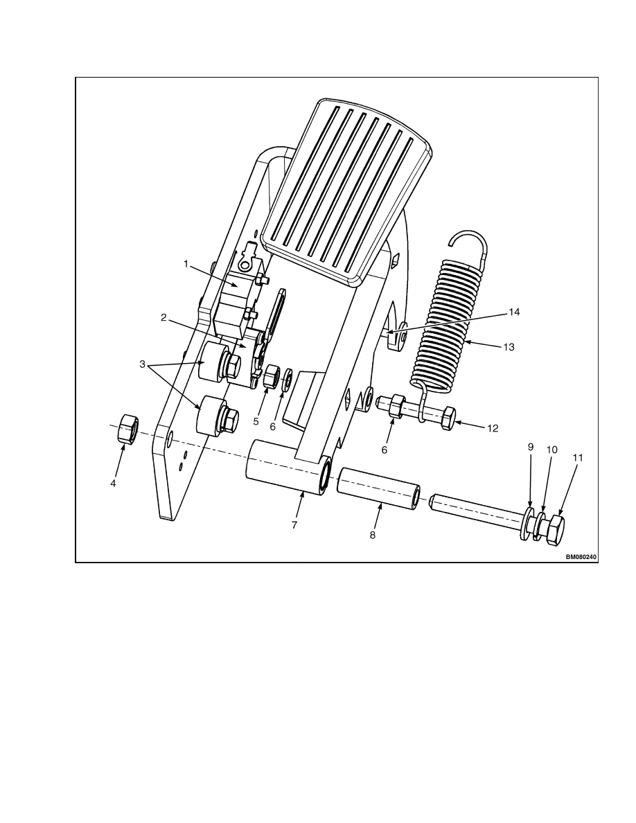
NOTE: Make sure the throttle position sensor arm is
installed to the pin on the accelerator pedal at instal-
lation. Refer to Figure 15.
5.
Install the throttle position sensor loosely to the
accelerator bracket using two screws, washers,
lockwashers, and nuts.
6.
Apply power and install a voltmeter to the throt-
tle position sensor:
a. Connect pin A of the throttle position sensor
connector to pin A of the main wiring harness
connector using a jumper wire.
b. Connect pin C of the throttle position sensor
connector to pin C of the main wiring harness
connector using a jumper wire.
c.
Connect the battery and turn the key switch
to the ON position.
d. Connect one voltmeter lead to the jumper
wire at pin C.
e.
Use the other voltmeter lead to probe pin B
of the throttle position sensor connector.
7.
Adjust the switches:
a. Adjust the throttle position sensor so that the
voltmeter reads 3.80 to 3.95 Volts with the
accelerator pedal in the full up position.
b. Tighten the screws to hold the throttle po-
sition sensor stationary. DO NOT OVER-
TIGHTEN.
c.
Position the neutral switch so that the actua-
tor is depressed just enough to click the con-
tacts inside the switch when the accelerator
pedal is in the full upright position.
d. Tighten the screws to hold the neutral switch
stationary. DO NOT OVERTIGHTEN.
e.
Depress the accelerator pedal just until
the neutral switch contacts click again and
HOLD.
13
Directional Controls
2200 SRM 1078
1.
CAPSCREW
2.
LOCKWASHER
3.
WASHER
4.
PEDAL STOP
5.
NEUTRAL SWITCH
6.
INSULATOR
7.
WASHER
8.
LOCKWASHER
9.
SCREW
10. NUT
11. SCREW
12. WASHER
13. LOCKWASHER
14. NUT
15. THROTTLE POSITION SENSOR
16. ACCELERATOR BRACKET
Figure 14. Accelerator Switches Installation
14
2200 SRM 1078
Directional Controls
1.
NEUTRAL SWITCH
2.
THROTTLE POSITION SENSOR
3.
PEDAL STOPS
4.
NUT
5.
NUT
6.
LOCKWASHER
7.
PEDAL
8.
BUSHING
9.
WASHER
10. LOCKWASHER
11. CAPSCREW
12. CAPSCREW
13. SPRING
14. PIN
Figure 15. Accelerator Switches
15

Directional Controls
2200 SRM 1078
f.
Verify that the voltmeter attached to the
throttle position sensor reads 3.64 to 3.69
Volts with the accelerator in this position.
Adjust as necessary.
g. Fully depress the accelerator pedal to the
lower stop and HOLD.
h. Verify that the voltmeter reads 0.54 to 0.36
Volts with the accelerator in this position.
Adjust as necessary.
i.
Torque neutral switch and throttle position
sensor screws to 2.2 N•m (19 lbf in).
8.
Turn the key switch to the OFF position and dis-
connect the battery.
9.
Remove the voltmeter and jumper wires from the
connectors.
10. Install the connector to the throttle position sen-
sor as removed.
11. Install the floor plates and floormat.
12. Calibrate the throttle position sensor to the con-
troller. See Calibrate.
CALIBRATE
1.
From the seat, turn the key switch to the ON
position.
2.
Press the Star key on the display panel two times
to display the password login screen.
3.
Enter the service password.
4.
Scroll up or down to “Setup” using button 1 and
button 2 on the display panel.
5.
Press button 4. “Traction Settings” will display.
6.
Press button 4. “Throttle Calibration” will dis-
play.
7.
Press button 4 again to initiate calibration mode.
WARNING
The truck should not accelerate in either di-
rection when the truck is in calibration mode.
SLOWLY depress the accelerator and check
that the truck does not move. NEVER perform
calibration around equipment or personnel in
case of unexpected movement of the lift truck
during calibration.
NOTE: Models equipped with the MONOTROL™
feature do not utilize a directional control lever. The
direction of travel is selected by pressing switches
on the left or right side of the accelerator pedal.
8.
Move the directional control lever to the forward
position if so equipped.
9.
Slowly depress the accelerator pedal until com-
pletely depressed and HOLD for one second to
set the forward throttle value.
10. Move the directional control lever to the reverse
position if so equipped.
11. Slowly depress the accelerator pedal until com-
pletely depressed and HOLD for one second to
set the reverse throttle value.
NOTE: The new calibration values may be canceled
at any time until the Star button is pressed. Press
button 3 to cancel calibration mode.
12. Press the Star button to save values. Slowly re-
lease the pedal and move the directional control
lever to the neutral position.
13. Press button 3 four times to completely back out
of service mode.
14. Test the truck for proper acceleration in a safe,
unobstructed area.
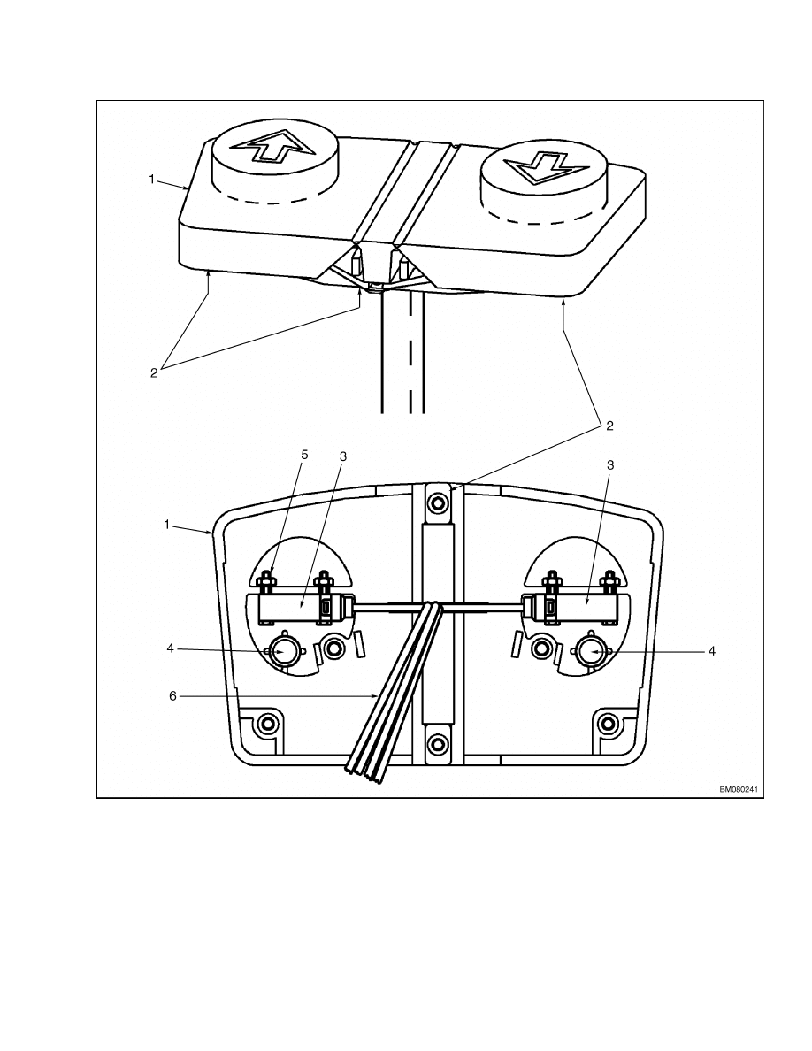
MONOTROL™ DIRECTIONAL CONTROL
An optional feature is the MONOTROL™ Direc-
tional Control pedal. This allows hand-free direc-
tional and speed control. Switches on the left and
right side of the MONOTROL™ Directional Control
pedal signal the controller which direction to travel.
Refer to Install. The speed and acceleration rate is
determined by how far the pedal is depressed, just
as the standard accelerator operates. See Figure 16.
16
2200 SRM 1078
Directional Controls
1.
COVER
2.
SCREWS
3.
SWITCHES
4.
SPRING
5.
ATTACHING HARDWARE
6.
WIRING HARNESS
Figure 16. MONOTROL™ Directional Control
17
Brakes
2200 SRM 1078
Brakes
BRAKE SWITCH
The brake switch is located below the floor plates
inside the brake pedal mounting bracket.
When
the service brake pedal is in its full up position, it
depresses the switch actuator. Pressing the brake
pedal, even a small distance, releases the actuator.
The controller monitors this circuit and reduces
power to the traction motors when the brake pedal
is depressed.
Adjust or Replace
To adjust the switch:
1.
Turn the key switch to the OFF position and dis-
connect the battery.
2.
Remove the floormat and floor plates.
3.
Depress and hold the brake pedal.
4.
Press the actuator of the switch up and down re-
peatedly to check that the switch return spring
functions correctly and listen for the "click" of the
contacts inside the switch.
5.
If in question, tag and disconnect the wiring and
remove the switch. Check with an ohmmeter.
Replace if necessary.
6.
Position switch to bracket as removed and install
screws and nutplate. Do not tighten.
or
7.
To adjust, loosen screws and nutplate holding
switch to bracket.
8.
With brake pedal in its full, upright position,
move the brake switch toward the brake pedal
until the actuator depresses and the contacts in
the switch click. Then tighten the screws to hold
the switch in place.
9.
Remove the screws and nutplate retaining the
switch to the brake pedal bracket. See Figure 17.
10. Position the switch against the brake pedal so
that the actuator is closed when the pedal is in
its upright position.
11. Retighten the screws to securely mount the
switch in place. DO NOT OVERTIGHTEN.
12. Reconnect the battery and turn the key switch to
the ON position and test for proper function.
1.
SCREWS
2.
BRAKE SWITCH
3.
INSULATOR
4.
NUTPLATE
5.
SERVICE PEDAL
6.
MASTER CYLINDER
7.
MOUNTING BRACKET
Figure 17. Brake Switch
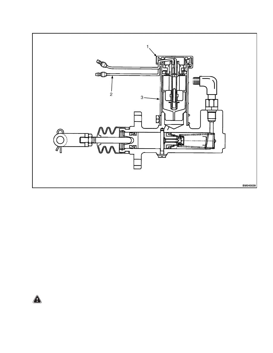
MASTER CYLINDER INDICATOR
The fluid level in the master cylinder reservoir is
monitored by a float switch, which is part of the reser-
voir cap. The switch is normally open when the reser-
voir is full. When the oil level in the master cylin-
der drops below the minimum safe level, the switch
closes and an indicator light on the display panel illu-
minates. If the indicator light does not come on when
the oil level is below the minimum safe level, check
the switch by disconnecting the cap wiring harness
and removing the cap assembly. Check that the float
moves smoothly and is completely sealed. Check the
switch for proper operation using an ohmmeter. Con-
nect the ohmmeter leads to each terminal and check
the resistance while moving the float up and down.
The resistance should increase from 0 to 470 ohms as
the float is moved. If the float does not move freely
or if the resistance in not within specification, re-
place the cap assembly with a new one and install
the wiring as removed. See Figure 18.
18
2200 SRM 1078
Brakes
1.
CAP ASSEMBLY
2.
SENSOR WIRES
3.
RESERVOIR
Figure 18. Master Cylinder Indicator Switch
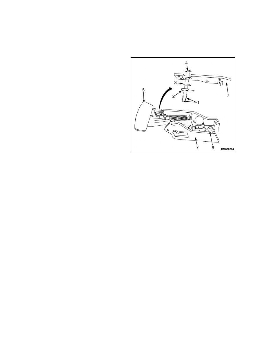
PARKING BRAKE DISENGAGE
The parking brakes must be disengaged to perform
certain repairs. When certain systems malfunction,
it may be necessary to tow the lift truck to a different
location to perform service. The parking brakes must
be disengaged to tow the truck, also. If towing, move
slowly and listen for sounds other than normal. If
the parking brakes do not release or there are other
signs of damage (noises), stop towing and repair on
site or carry the lift truck using a larger lift truck
if possible. See Periodic Maintenance 8000 SRM
1079, General for proper towing procedures.
Override Mode
WARNING
The following procedures refer to overriding
the parking brakes for repair or service in
a controlled environment.
Additional pre-
cautions and procedures are required when
towing. See Periodic Maintenance 8000 SRM
1079, How to Tow Lift Truck.
To disengage the parking brake in order to perform
service:
1.
Turn the key switch to the OFF position and dis-
connect the battery by pressing the emergency
disconnect switch to the STOP position.
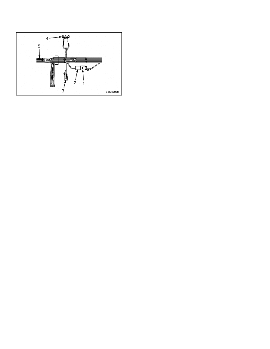
2.
Locate the parking brake connectors (BRK_RUN
1, BRK_RUN 2, and the BRK_TOWING) beside
the brake diode on the main wiring harness.
These items are found near the front, right
wheel well. See Figure 19.
19
Horn Components and Steering Encoder
2200 SRM 1078
1.
BRK_RUN 1
2.
BRK_RUN 2
3.
BRK_TOWING
4.
BRAKE DIODE
5.
MAIN WIRING HARNESS
Figure 19. Brake Diode and Release Connectors
3.
If a charged battery is not installed in the lift
truck, use special tool - Auxiliary Battery Con-
nector (Hyster™ P/N 1564329):
a. Disconnect the BRK_RUN 1 and BRK_RUN
2 connectors.
Connect the auxiliary battery connector to
the BRK_RUN 2 connector.
b. Connect the jumper wires to the 24-volt aux-
iliary power source and listen for the parking
brakes to release.
4.
If a charged battery is installed in the lift truck,
energize the brake override circuit:
a. Disconnect the BRK_RUN 1 and BRK_RUN
2 connectors.
b. Connect the BRK_TOWING and BRK_RUN
2 connectors.
c.
Pull the emergency disconnect switch to the
RUN position and listen for the parking
brakes to release.
5.
Return the truck to operation mode and test for
proper operation before returning to service.
Horn Components and Steering Encoder
HORN COMPONENTS
If the horn does not operate properly, there are differ-
ent components that may be at fault. To determine
if the horn itself is faulty, check that 36/48 volts DC
are present at the terminals when the horn button is
depressed.
1.
Turn the key switch to the OFF position and dis-
connect the battery. Block the wheel to prevent
unexpected movement.
2.
Tag and disconnect the wiring harness connected
to the terminals on the horn. See Figure 20.
3.
Connect a voltmeter lead to each end of the
wiring harness connectors.
4.
Connect the battery and turn the key switch to
the ON position.
5.
Press the horn button in the center of the steer-
ing wheel.
a. If the voltmeter does not read 36/48 ±5 volts,
troubleshoot the horn button, horn contacts,
and wiring.
b. If the voltmeter does read 36/48 ±5 volts, re-
place the horn.
Horn
The horn is the actual audible alarm and is mounted
to the cowl facing forward. To replace the horn, refer
to the following procedures.
1.
Remove the cowl cover by removing the four at-
taching screws.
2.
Tag and disconnect the wires fastened to the horn
terminals.
3.
Hold the horn and remove the capscrew, nut,
and washer that fasten the horn to the bracket
welded to the lift truck cowl. Remove the horn.
4.
Install the new horn and secure using capscrew,
lockwasher, and nut as removed.
5.
Install the wires on the horn terminals.
6.
Connect the battery and test for proper opera-
tion.
20
2200 SRM 1078
Horn Components and Steering Encoder
7.
Reinstall the cowl cover using the four attaching
screws.
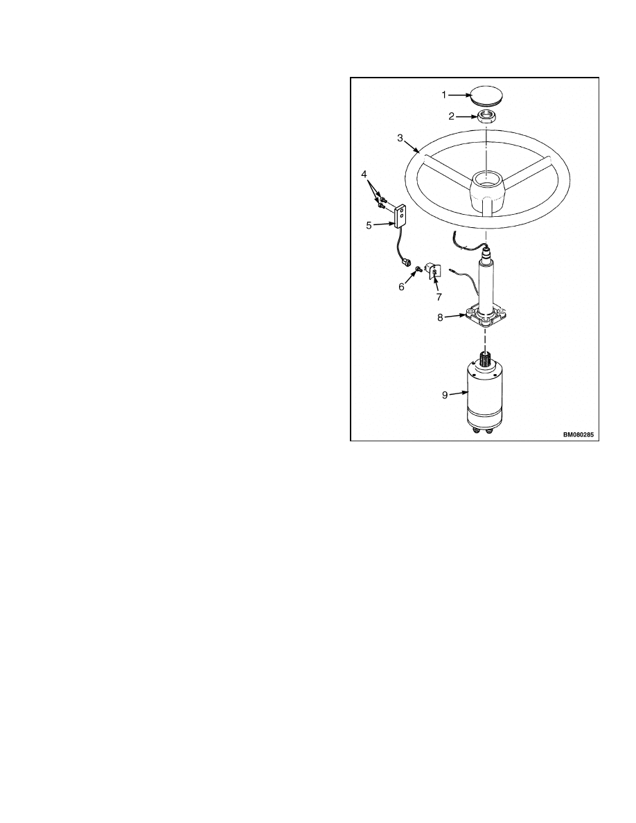
Horn Button and Contacts
The horn button and contacts are located on the
steering column. The contacts are mounted on the
front of the steering column, just above the steering
encoder. The horn button, which actuates the con-
tacts, is made into the steering wheel cap. Wires
run from the horn button to the contacts through the
steering column. See Figure 20.
STEERING ENCODER
The steering encoder is fastened to the steering col-
umn with two screws. See Figure 20. Remove the
steering column covers to access the encoder.
1.
HORN BUTTON
2.
STEERING WHEEL NUT
3.
STEERING WHEEL
4.
SCREWS
5.
HORN CONTACTS
6.
SCREW
7.
STEERING ENCODER
8.
STEERING COLUMN
9.
STEERING CONTROL UNIT
Figure 20. Horn Switch and Steering Encoder
21
Steer Angle Potentiometer
2200 SRM 1078
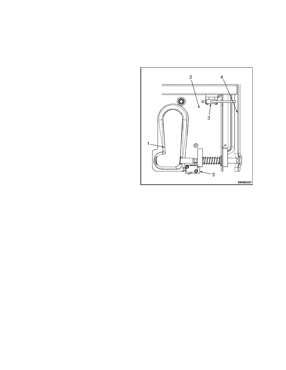
Hood and Seat Switches
HOOD POSITION SWITCHES
The hood functions as a restraint to hold the battery
in the battery compartment if an accident causes the
lift truck to tip over. A sliding latch mechanism on
the front of the hood locks it closed during operation.
The latch can be accessed by releasing and raising
the hydraulic levers and linkage assembly up and out
of the way. A switch is mounted to the underside of
the hood beside the latch pin. The actuator of the
switch is depressed when the latch pin is in the open
position. The actuator slides down the side of the
latch pin and rests in the groove in the latch pin when
the latch is closed. If the switch actuator does not
enter completely into the groove, the lift truck will
not operate.
A second switch mounted to the right, front under-
side of the hood senses the position of the hood it-
self. The switch actuator is normally depressed by
the truck frame when the hood is in the fully closed
position. When the hood is lifted, the actuator is re-
leased and the controller will not allow the lift truck
to operate. See Figure 21.
SEAT SWITCH
The seat assembly contains an operator presence
switch as a safety feature. The seat wiring harness
connects to switch and exits through the bottom of
the seat assembly. The operator presence switch is
located inside the bottom seat cushion. When an
operator sits in the seat, the switch alerts the motor
controller to operate normally.
If the operator is
not in the seat, neither the lift pump motor nor the
traction motors will operate.
1.
HANDLE RECESS
2.
HOOD (UNDERSIDE)
3.
HOOD POSITION SWITCH
4.
FRAME
5.
LATCH POSITION SWITCH
Figure 21. Hood Position Switches
Steer Angle Potentiometer
GENERAL
The steer angle potentiometer measures the position
of the steer axle and relays this information to the
traction motor controller. The controller can then
modify individual drive motor speeds to improve
the truck’s turning performance. The potentiometer
facilitates a voltage divider circuit and is rated at
10,000 ohms.
The steer angle potentiometer is mounted to the
mounting arm which pivots on the arm stop cap-
screw. The potentiometer shaft is attached to the top
of the rotary actuator by a holder and setscrew. The
steer angle potentiometer is accessible through the
electrical compartment and must be mounted in the
correct orientation to the steering axle before it can
be properly calibrated. A status code is displayed
when the potentiometer is greatly out of adjustment.
However, a potentiometer that is moderately out of
adjustment may continue to operate. The absence of
a status code does NOT necessarily mean that the
potentiometer is properly adjusted.
OPERATION
When the steering potentiometer is properly ad-
justed and operating correctly, the input voltage
measured at the traction motor controller is between
the full left and full right calibration values and
corresponds to the turn angle of the drive tire. The
controller retards the traction motor on the side to
22
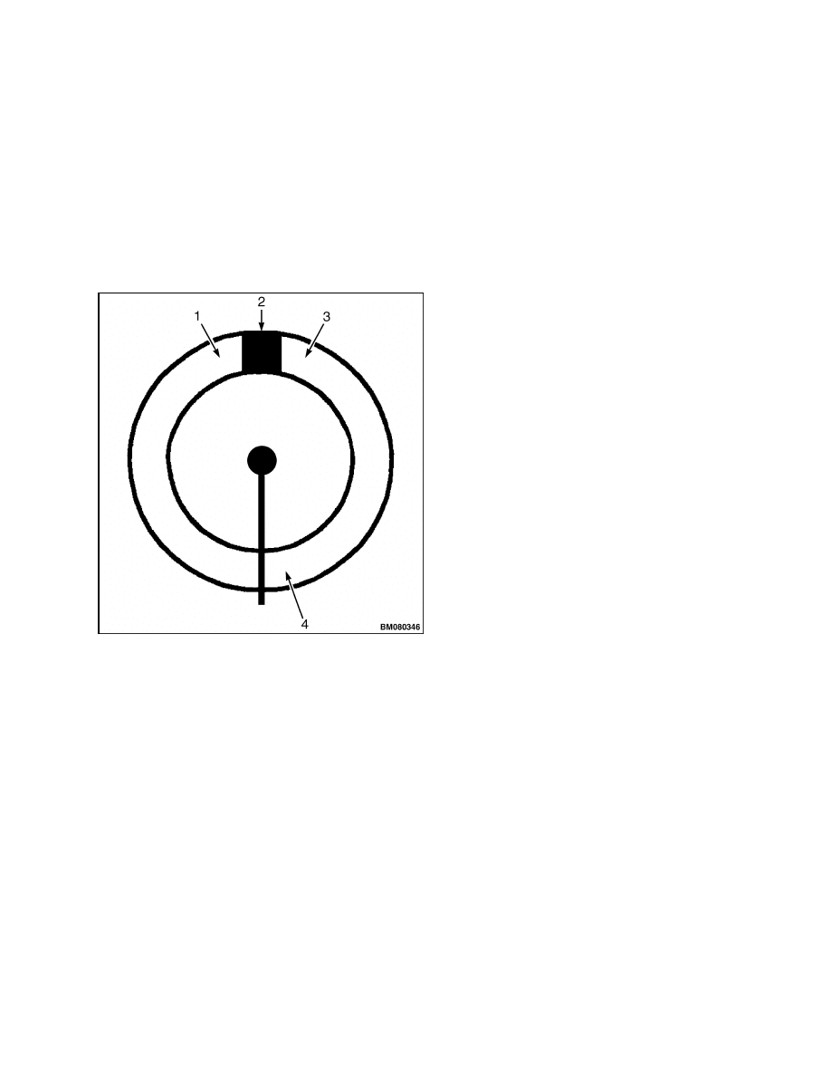
2200 SRM 1078
Steer Angle Potentiometer
which the steer tire is turned to improve the truck’s
turning radius. When the drive tire is positioned
straight ahead (0-degree turn angle), the input volt-
age at the controller should be 2.2 ±0.1 volts. As the
steer tire is turned left, the input voltage decreases
and the speed of the left side traction motor is re-
duced. As the steer tire is turned right, the input
voltage increases and the speed of the right side
traction motor is reduced. Refer to Figure 22 for the
correlation between the turn angles of the steer tire
and the input voltages to the controller.
1.
LOWEST VOLTAGE (HIGH RESISTANCE)
2.
DEAD AREA (INFINITE RESISTANCE)
3.
HIGHEST VOLTAGE (LOW RESISTANCE)
4.
MIDPOINT
Figure 22. Potentiometer Input
Example
The following series of events takes place in a left
turn from the 0- to 90-degree steer wheel position.
In the first 25 degrees of travel (2.15 to 1.81 wiper
volts), there is no change to the wheel speed on the
inside of the turn (left wheel).
Between 25 degrees (1.81 wiper volts) and 66 de-
grees (1.10 wiper volts), the left motor reduces speed
proportionally from top speed at 25 degrees to creep
speed at 66 degrees.
Beyond 32 degrees, the maximum lift truck speed is
reduced. The maximum lift truck speed is reduced
from full speed at 32 degrees to the value set by Func-
tion 11 at 90 degrees.
Between 66 degrees and 71 degrees, the left wheel is
in a free-wheel mode.
As the steer angle reaches the 71-degree point, the
left wheel begins to turn in the opposite direction and
accelerate proportionally.
Beyond 86 degrees, the steer angle potentiometer is
outside the normal range of travel.
POSITION STEER TIRE FOR STRAIGHT
TRAVEL
The steer tire must be positioned so the truck trav-
els in a straight line within 152 mm (6 in.) over a
distance of 9 m (30 ft) before adjustments are made
to the steer angle potentiometer.
The following
procedure is used to verify that the truck travels
in a straight line for 9 m (30 ft). If the truck does
not travel straight within the tolerance allowed, the
steer tire should be repositioned using the steering
control handle until the truck can be operated in a
straight line, as described, within the specified tol-
erance. The steer tire must be exactly positioned for
straight travel before adjustments can be properly
made to the steer angle potentiometer.
NOTE: This procedure requires a section of floor that
is smooth and level for approximately 30 m (100 ft).
1.
Move the steering control wheel so the steer
tire is positioned for straight travel.
Operate
the lift truck slowly, while holding the steering
wheel stationary, for 9 m (30 ft). The steer tire
is in the proper position when the lift truck will
travel within 152 mm (6 in.) of a straight line for
9 m (30 ft). Check that the lift truck moves in a
straight line as follows:
a. Install a pointer on the outside of the lift
truck, forward of the counterweight.
The
pointer should be positioned so it does not
touch the floor. A wire tie can be secured to
the frame with duct tape to serve as a pointer.
b. Mark the floor under the point of the pointer.
c.
Operate the lift truck slowly for 5 m (16 ft).
The operator should not move the steering
control handle while traveling, and the lift
23
Steer Angle Potentiometer
2200 SRM 1078
truck should coast to a stop. Mark the floor
under the point of the pointer.
d. Operate the lift truck slowly in the same di-
rection for another 5 m (16 ft). The opera-
tor should not move the steering control han-
dle while traveling and allow the lift truck
to coast to a stop. Mark the floor under the
point of the pointer.
e.
With an assistant, pull a string in a straight
line between the first and last marks. The
center mark must be within 76 mm (3 in.) of
the string. If the center mark is not within
76 mm (3 in.), the steer tire is positioned in-
correctly. Reposition the steer tire with the
steering wheel and repeat this procedure un-
til the steer tire is correctly positioned.
f.
Remove the pointer.
2.
When the steer tire has been correctly positioned,
the steer angle potentiometer can be installed.
INSTALL
Set Potentiometer to Midpoint
For the following procedures, refer to Figure 22.
NOTE: The steer tire cannot be seen from the seat.
Have an assistant watch the steering tire and advise
you of its position.
1.
On a clean workbench, touch the leads of an ohm-
meter to the middle and one of the outside pins
on the steering potentiometer connector.
2.
Position the potentiometer shaft where its high-
est resistance (infinity) and its lowest resistance
meet.
a. Turn the potentiometer shaft until the ohm-
meter reaches it highest resistance (infinity).
b. Draw a straight, continuous line down the
shaft and onto the base of the potentiometer,
using a marker to mark the position.
CAUTION
Do not move the shaft of the potentiometer
after this point.
If the shaft is accidentally
moved, realign the marks on the potentiome-
ter and shaft (Step b) and continue from Step 3.
3.
Turn the potentiometer arm 180 degrees to the
midpoint. The ohmmeter should read approxi-
mately 5000 ohms. Remove the ohmmeter leads.
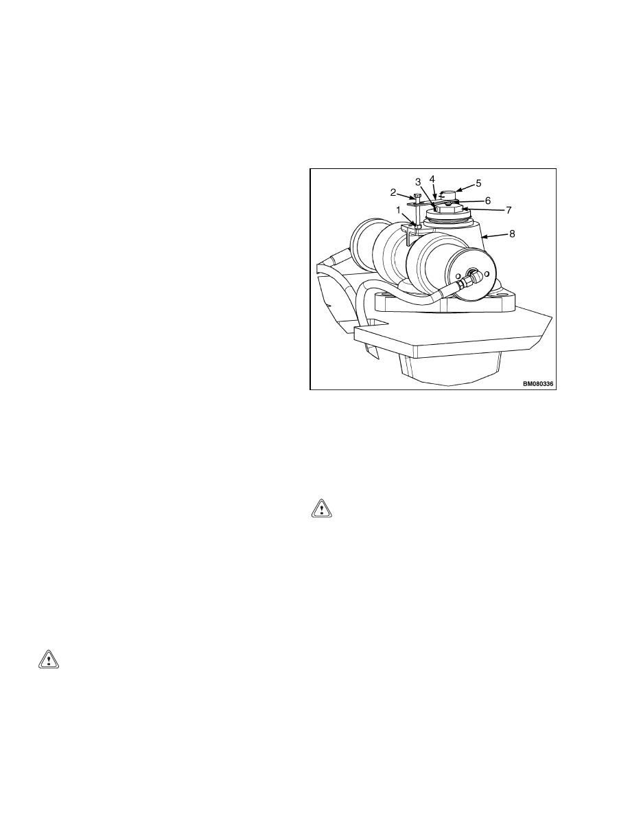
Install to Steer Axle
For the following procedures, refer to Figure 23.
1.
JAM NUT
2.
ARM STOP
CAPSCREW
3.
SETSCREW
4.
MOUNTING ARM
5.
POTENTIOMETER
6.
MOUNTING
HARDWARE
7.
HOLDER
8.
STEER AXLE
HOUSING
Figure 23. Steer Potentiometer Mounting
CAUTION
Be careful not to move the potentiometer shaft
when installing to the steering actuator. If the
shaft is accidentally moved, realign the marks
on the potentiometer and shaft (Step b) and
continue from Step 3.
1.
Remove the hardware from the potentiometer,
install the potentiometer to the mounting arm,
and reinstall hardware. Position the potentiome-
ter with its wiring harness toward the slot in the
mounting arm and torque the nut to 1.24 N•m
(11 lbf in) to secure in position.
2.
Make sure the steer tires are positioned for
straight travel.
See Position Steer Tire for
Straight Travel.
3.
Turn the key switch to the OFF position and dis-
connect the battery.
24

2200 SRM 1078
Steer Angle Potentiometer
4.
Install the arm stop capscrew down through the
slot on the mounting arm and into the steering
actuator housing and tighten the jam nut.
5.
Carefully position the potentiometer (shaft
down) into the holder.
6.
Tighten the holder setscrew to secure the poten-
tiometer shaft in place.
7.
Connect the potentiometer wiring harness, as re-
moved. Use a new wire tie to secure it to the arm
stop capscrew.
8.
Reconnect the battery and calibrate the steering
potentiometer using the display panel. See Cali-
brate.
Calibrate
The following procedures use the display panel to cal-
ibrate the controller values for the steering poten-
tiometer. Refer to Figure 9.
1.
From the seat, turn the key switch to the ON
position.
2.
Press the Star button on the display panel two
times to display the password login.
3.
Enter the service password.
4.
Press button 1 or button 2 to scroll to “Setup.”
5.
Press button 4. “Traction Settings” will display.
6.
Press button 4. “Throttle Calibration” will dis-
play.
7.
Press button 1 or button 2 to scroll to “Max Steer
Right” and press button 4 to display the current
values.
8.
Press button 4 again to initiate calibration mode.
9.
Slowly turn and hold the steering wheel in its full
right position.
10. Press the Star button to save the values.
11. Press button 3 to back out one level.
12. Press button 1 or button 2 to scroll to “Max Steer
Left.” Press button 4 to display the current val-
ues.
13. Press button 4 to initiate calibration mode.
14. Slowly turn the steering wheel to the full left po-
sition.
15. Press the Star button to save the values.
16. Press button 3 to back out on level.
17. Press button 1 or button 2 to scroll to “Max Steer
0.” Press button 4 to display the current values.
18. Press button 4 again to initiate calibration mode.
NOTE: The steer tire cannot be seen from the seat.
Have an assistant watch the steering tire and advise
you of its position.
19. Turn the steering wheel to position the steer tires
for straight travel.
20. Press the Star button to save the values.
21. Press button 3 four times to completely back out
of service mode.
22. Test the truck for proper operation in a safe, un-
obstructed area.
TEST
The steer angle potentiometer is tested by measur-
ing resistance values after disconnecting the poten-
tiometer from the truck wiring harness. Refer to Ta-
ble 1. Connect an analog volt-ohmmeter to the de-
sired test points and slowly rotate the potentiome-
ter shaft. The needle on the meter should sweep
smoothly from the minimum to maximum value. Re-
place the potentiometer if the needle movement is er-
ratic through the range from minimum to maximum.
Table 1. Potentiometer Specifications
Test Points
Resistance Value
Between pot terminals
1 and 3
10K
±10%
Between pot terminals
1 and 2
0-10K
±10%
Between pot terminals
2 and 3
0-10K
±10%
25

Wiring Harness
2200 SRM 1078
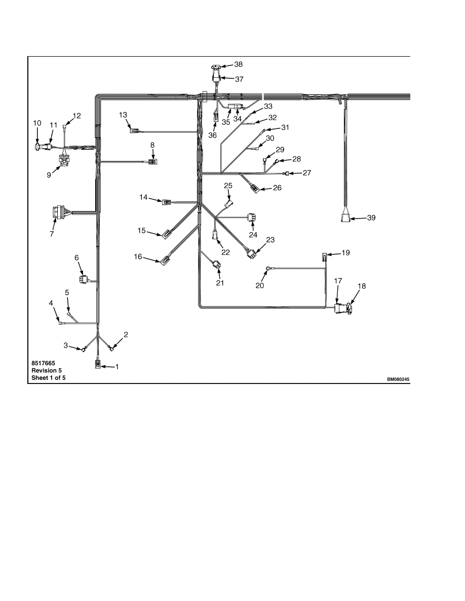
Wiring Harness
The wiring harness is a series of wires bound to-
gether which carry power and electrical signals
throughout the electrical system.
The controller
monitors signals from various sensors through the
wiring harness and sends instructions and power
for different components. Resistor assemblies are
present throughout the wiring harness to protect
certain systems.
If there is damage to the wiring harness, it may be
possible to replace only a few wires instead of the
entire wiring harness. Wires and cables do not nor-
mally need replacing. Make sure the wire or cable is
damaged before it is replaced. Make sure malfunc-
tions in the system are not being caused by a con-
nector or connection before replacing wires or compo-
nents. Determine the cause of the damage and rec-
tify the problem before correcting the wiring to pre-
vent the same problems from occurring again. If a
wire or cable is damaged, replace the wire and any
connectors using the correct size and type replace-
ment parts. For specific wiring harness functions,
see Figure 24.
26

2200 SRM 1078
Wiring Harness
Legend for Figure 24
1.
Steer Encoder (SE)
2.
Horn Switch (HS2)
3.
Horn Switch (HS1)
4.
Key Switch (Run)
5.
Key Switch (Bat)
6.
Directional Switches
7.
Dash
8.
PC Connection
9.
Valve Controller
10. CANbus Resistor
11. Resistor Connector
12. (MJ)
13. Hydraulic Tank Level
14. Tilt Speed
15. RH Traction Motor
16. LH Traction Motor
17. Resistor Connector
18. CANBUS Resistor
19. Steer Pump Motor
20. Steer Positive
21. Horn
22. Brake Coil (C3)
23. Lift Pump
24. Brake Pedal
25. Brake Coil (C2)
26. Throttle Sensor
27. Directional Control (FC3)
28. Directional Control (FC2)
29. Directional Control (FC1)
30. Start Traction (SW1)
31. Start Traction (SW2)
32. Brake Fluid (MC1)
33. Brake Fluid (MC2)
34. BRK RUN (1)
35. BRK RUN (2)
36. BRK TOWING
37. Diode Connector
38. Brake Diode
39. Control Valve
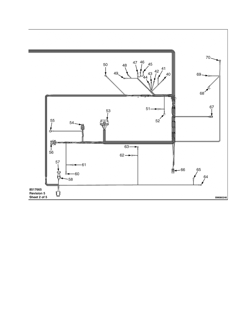
40. Fuse (FU15B)
41. Fuse (FU12B)
42. Fuse (FU14B)
43. Fuse (FU13B)
44. Fuse (FU11B)
45. Fuse (FU14A)
46. Fuse (FU13A)
47. Fuse (FU11A)
48. Fuse (FU12A)
49. Fuse (FU15A)
50. EHB Ground
51. Main Contactor (C1)
52. Main Contactor (C2)
53. Controller (TBC)
54. Controller (TBA)
55. TC Negative
56. Controller (TBD)
57. Resistor
58. Connector
59. Seat
60. Hydraulic Contactor (C1)
61. Hydraulic Contactor (C2)
62. Hood Switch (SW1A)
63. Hood Switch (SW1B)
64. Hood Switch (SW2A)
65. Hood Switch (SW2B)
66. Auxiliary Connector
67. Steering Potentiometer
68. Emergency Shutoff (ES2)
69. Emergency Shutoff (ES1)
70. Battery Positive
27
Wiring Harness
2200 SRM 1078
28
2200 SRM 1078
Wiring Harness
Figure 24. Wiring Harness
29

NOTES
____________________________________________________________
____________________________________________________________
____________________________________________________________
____________________________________________________________
____________________________________________________________
____________________________________________________________
____________________________________________________________
____________________________________________________________
____________________________________________________________
____________________________________________________________
____________________________________________________________
____________________________________________________________
____________________________________________________________
____________________________________________________________
____________________________________________________________
____________________________________________________________
____________________________________________________________
____________________________________________________________
____________________________________________________________
____________________________________________________________
30


TECHNICAL PUBLICATIONS
2200 SRM 1078
7/05 (11/04)(6/04) Printed in United Kingdom
Document Outline
- toc
- tables
Wyszukiwarka
Podobne podstrony:
1468474 2200SRM0756 (07 2005) UK EN
1580519 2200SRM1131 (07 2005) UK EN
1534735 2200SRM1056 (07 2005) UK EN
1459370 1600SRM0720 (07 2005) UK EN
1596602 0100SRM1200 (07 2005) UK EN
1586985 2200SRM1178 (03 2005) UK EN
1580518 2200SRM1130 (06 2005) UK EN
897961 2200SRM0647 (03 2005) UK EN
1580521 2200SRM1143 (05 2005) UK EN
1596605 8000SRM1203 (07 2005) UK EN
1534732 0620SRM1053 (07 2005) UK EN
1595265 2200SRM1204 (01 2005) UK EN
1589731 2200SRM1184 (03 2005) UK EN
1534733 1600SRM1054 (07 2005) UK EN
1556364 0620SRM1098 (07 2005) UK EN
więcej podobnych podstron