STEERING SYSTEM
FOR AC ELECTRIC
LIFT TRUCKS
J2.00-3.20XM (J40-65Z) [A416];
E1.50-2.00XM (E25-35Z, 40ZS) [E114];
V30ZMD [D210]; E2.00-3.20XM (E45-65Z) [G108];
E3.50-5.50XL, E4.50XLS
(E70-120Z, E100ZS) [D098]
PART NO. 1534733
1600 SRM 1054

SAFETY PRECAUTIONS
MAINTENANCE AND REPAIR
• When lifting parts or assemblies, make sure all slings, chains, or cables are correctly
fastened, and that the load being lifted is balanced. Make sure the crane, cables, and
chains have the capacity to support the weight of the load.
• Do not lift heavy parts by hand, use a lifting mechanism.
• Wear safety glasses.
• DISCONNECT THE BATTERY CONNECTOR before doing any maintenance or repair
on electric lift trucks. Disconnect the battery ground cable on internal combustion lift
trucks.
• Always use correct blocks to prevent the unit from rolling or falling. See HOW TO PUT
THE LIFT TRUCK ON BLOCKS in the Operating Manual or the Periodic Mainte-
nance section.
• Keep the unit clean and the working area clean and orderly.
• Use the correct tools for the job.
• Keep the tools clean and in good condition.
• Always use HYSTER APPROVED parts when making repairs. Replacement parts
must meet or exceed the specifications of the original equipment manufacturer.
• Make sure all nuts, bolts, snap rings, and other fastening devices are removed before
using force to remove parts.
• Always fasten a DO NOT OPERATE tag to the controls of the unit when making repairs,
or if the unit needs repairs.
• Be sure to follow the WARNING and CAUTION notes in the instructions.
• Gasoline, Liquid Petroleum Gas (LPG), Compressed Natural Gas (CNG), and Diesel fuel
are flammable. Be sure to follow the necessary safety precautions when handling these
fuels and when working on these fuel systems.
• Batteries generate flammable gas when they are being charged. Keep fire and sparks
away from the area. Make sure the area is well ventilated.
NOTE: The following symbols and words indicate safety information in this
manual:
WARNING
Indicates a condition that can cause immediate death or injury!
CAUTION
Indicates a condition that can cause property damage!

Steering System for AC Electric Lift Trucks
Table of Contents
TABLE OF CONTENTS
General ...............................................................................................................................................................
Description .........................................................................................................................................................
Steering Wheel and Column Assembly Repair ................................................................................................
General ...........................................................................................................................................................
Assembly Components, Remove ...................................................................................................................
Assembly Components, Install .....................................................................................................................
Power Steering Motor and Pump ......................................................................................................................
Description .....................................................................................................................................................
Remove ...........................................................................................................................................................
Disassemble ...................................................................................................................................................
Install .............................................................................................................................................................
Power Steering Pump, Repair.......................................................................................................................
Seal, Replace..............................................................................................................................................
Steering System Air Removal ...........................................................................................................................
Steering Pressure Check ...................................................................................................................................
Steering Motor Circuits Check..........................................................................................................................
Troubleshooting..................................................................................................................................................
This section is for the following models:
J2.00-3.20XM (J40-65Z) [A416];
E1.50-2.00XM (E25-35Z, 40ZS) [E114];
V30ZMD [D210];
E2.00-3.20XM (E45-65Z) [G108];
E3.50-5.50XL, E4.50XLS (E70-120Z, E100ZS) [D098]
©2005 HYSTER COMPANY
i

"THE
QUALITY
KEEPERS"
HYSTER
APPROVED
PARTS

1600 SRM 1054
Description
General
This section covers the description, disassembly, as-
sembly, checks, adjustments, and troubleshooting of
the steering system. See Figure 1. There is a de-
scription for each part of the steering system at the
beginning of each repair section. See the Steering
Axle SRM for your vehicle for the description and
repair procedures for the steering cylinder.
Description
The steering system used on this lift truck is a
hydraulic system that does not have a mechanical
connection between the steering wheel and steer-
ing axle. The control of the steering is through a
hydraulic circuit. See Figure 1 and Figure 2. An
electric motor drives a hydraulic pump. To energize
the motor, the key switch must be ON and the seat
switch must be closed. After the starting sequence is
completed, the electric motor on the Power Steering
pump will run continuously at low speed. As the
wheel is turned, the electric motor will increase
its speed to meet the steering demand. When the
electric motor operates the pump, hydraulic oil flows
through the power steering system.
As the steering wheel is moved to steer the lift
truck, the steering sensor detects the movement
of the steering shaft.
The steering sensor sends
a signal to the motor to increase or decrease the
motor speed proportional to the speed that the
steering wheel is turned.
For more information,
see the section Electrical Diagrams, AC Motor
Control System 8000 SRM 1059 for lift truck
models J2.00-3.20XM (J40-65Z) (A416), V30ZMD
(D210), E1.50-2.00XM (E25-35Z, E40ZS) (E114),
and E2.00-3.20XM (E45-65Z) (G108). See the sec-
tion Diagrams, AC Motor Control System 8000
SRM 1203 for lift trucks E3.50-5.50XL, E4.50XLS
(E70-120Z, E100ZS) (D098). for the electrical con-
nections for Power Steering with the On-Demand
system. The steering control unit is also operated
by the steering wheel to direct oil to the steering
cylinder.
The steering wheel also operates the steering con-
trol unit. When the steering wheel is rotated to steer
the lift truck, the hydraulic oil is sent to the steering
cylinder on the steering axle.
The steering control unit is a rotary valve operated
by the steering wheel. During the steering operation,
the steering control unit controls the direction of flow
and volume of oil to control the direction and degree
of turn. Hydraulic oil returns from the cylinder to
the steering control unit and then returns to the hy-
draulic tank.
If for any reason the steering pump does not oper-
ate, a check valve permits the steering control unit
to still control the steering system. The lift truck is
difficult to steer when the steering pump is not op-
erating, but the steering control unit can operate the
steering cylinder and makes steering possible.
1
Description
1600 SRM 1054
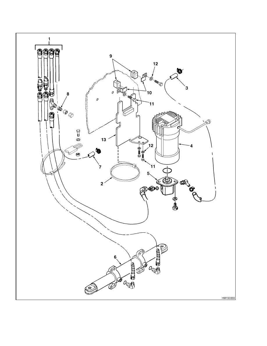
Figure 1. Power Steering Components (Typical)
2
1600 SRM 1054
Steering Wheel and Column Assembly Repair
Legend for Figure 1
1.
TO STEERING CONTROL UNIT
2.
METAL BAND (HOLDS PUMP MOTOR TO
MOUNTING WELDMENT)
3.
FROM HYDRAULIC TANK
4.
PUMP MOTOR
5.
STEERING PUMP
6.
STEERING CYLINDER
7.
RETURN TO HYDRAULIC TANK
8.
PRESSURE CHECK FITTING
9.
RUBBER CHANNELS
10. MOUNTING BRACKETS
11. CAPSCREW
12. WASHER
13. MOUNTING WELDMENT
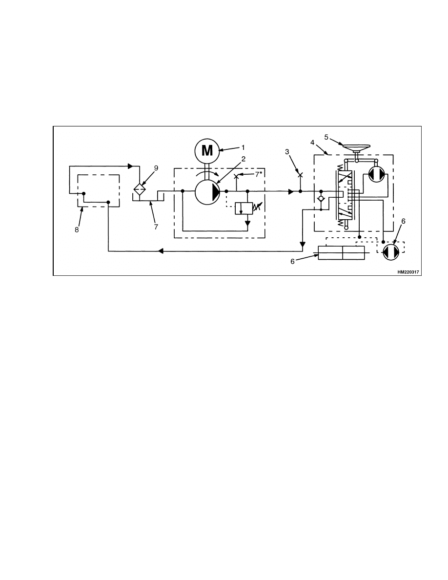
1.
MOTOR
2.
STEERING PUMP
3.
PRESSURE TEST PORT
4.
STEERING CONTROL UNIT
5.
STEERING WHEEL
6.
STEERING CYLINDER
7.
HYDRAULIC TANK
8.
MAIN CONTROL VALVE
9.
FILTER
Figure 2. Steering System Hydraulic Schematic
Steering Wheel and Column Assembly Repair
GENERAL
The upper end of the steering shaft has splines for the
steering wheel. A large hex nut holds the steering
wheel onto the steering shaft. The horn button is the
cover for the center of the steering wheel. The lower
end of the steering column has splines or a tang to
engage the steering control unit. See Figure 3.
The steering column is adjustable and is held in po-
sition by a latch. The steering column position can
be changed for different operators. The steering col-
umn must be raised to the UP position to provide
clearance for the seat when removing or installing
the battery. There is a cover on the steering column
for access to the steering control unit, key switch,
horn switch, direction switch (if installed), and steer-
ing sensor.
ASSEMBLY COMPONENTS, REMOVE
NOTE: This procedure is for the removal of all com-
ponents of the steering column assembly. Usually, it
is not necessary to remove all of the components. Do
only those steps of the procedure necessary to remove
the component you need to remove. To make repairs
to the steering control unit, see the section Steering
Housing and Control Unit 1600 SRM 720.
3
Steering Wheel and Column Assembly Repair
1600 SRM 1054
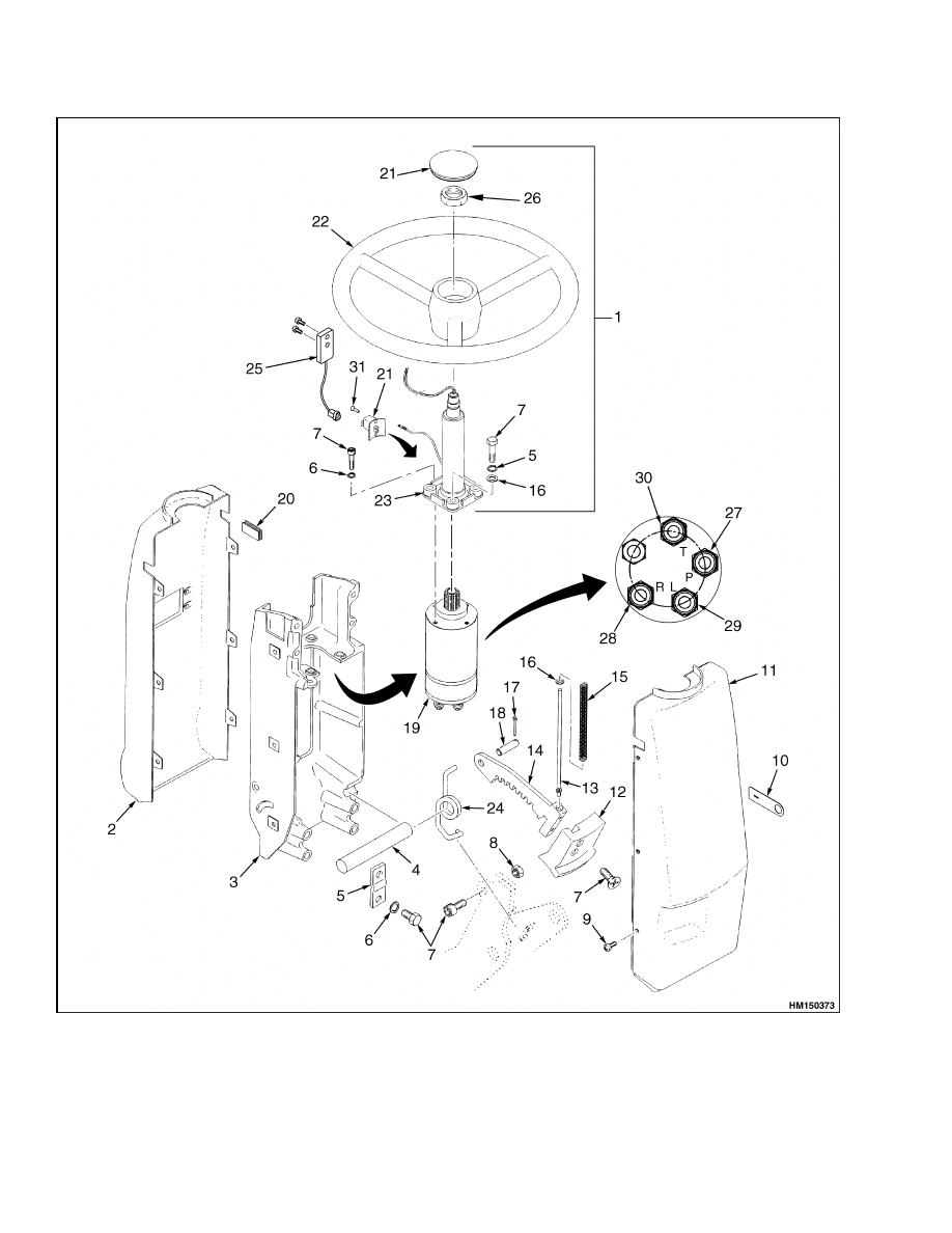
Figure 3. Steering Column Assembly
4
1600 SRM 1054
Steering Wheel and Column Assembly Repair
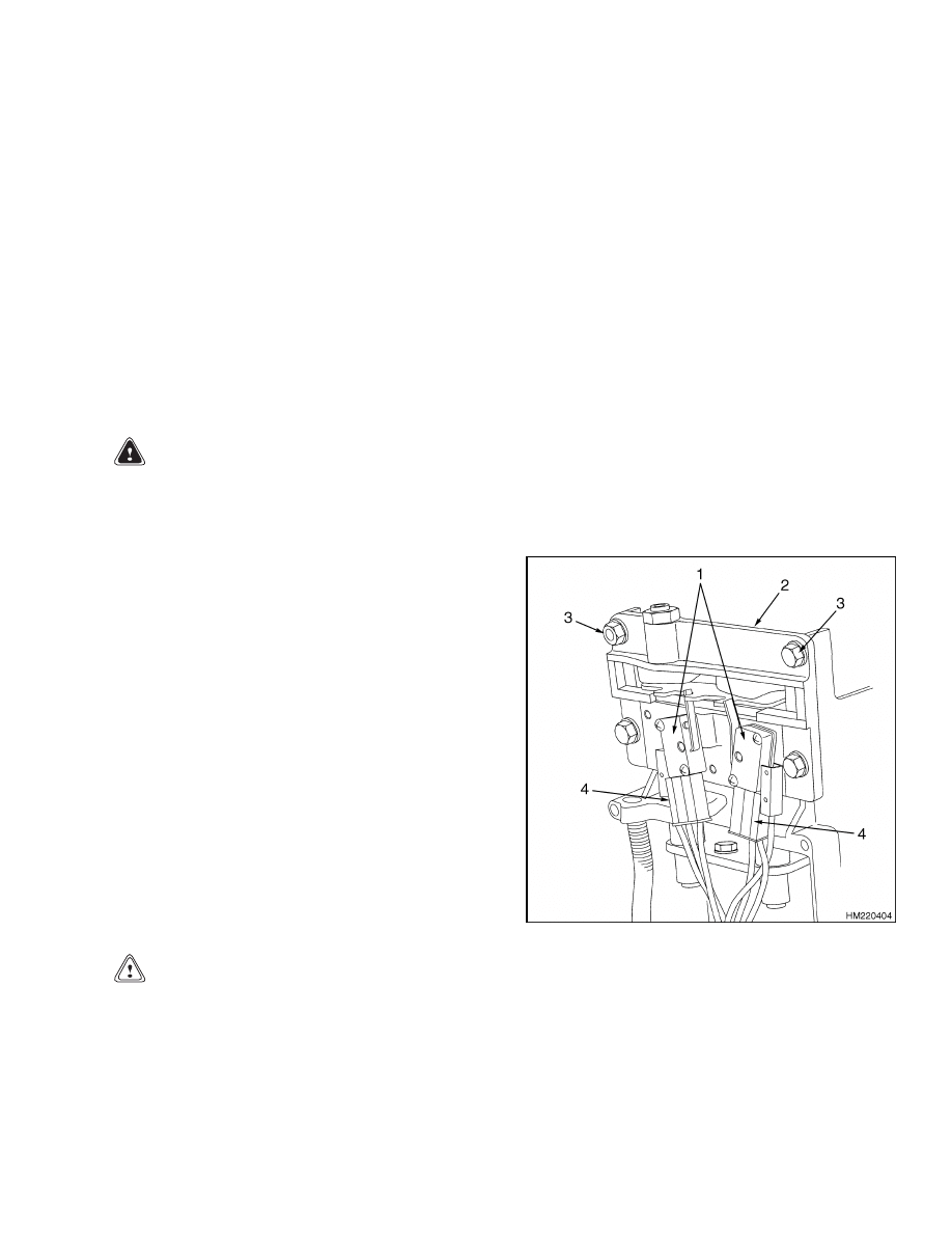
Legend for Figure 3
NOTE: FOR CORRECT CONNECTION, SEE THE ELECTRICAL DIAGRAMS, AC MOTOR CONTROL SYSTEM
8000 SRM 1059 FOR LIFT TRUCK MODELS J2.00-3.20XM (J40-65Z) (A416), V30ZMD (D210), E1.50-2.00XM
(E25-35Z, E40ZS) (E114), AND E2.00-3.20XM (E45-65Z) (G108). SEE DIAGRAMS, AC MOTOR CONTROL SYS-
TEM 8000 SRM 1203 FOR LIFT TRUCK MODELS E3.50-5.50XL, E4.50XLS (E70-120Z, E100ZS) (D098).
1.
ON-DEMAND STEERING
COMPONENTS
2.
UPPER ACCESS COVER
3.
BRACKET
4.
PIVOT (STEERING) SHAFT
5.
PLATE
6.
LOCKWASHER
7.
CAPSCREW
8.
LOCK NUT
9.
SCREW
10. STATIC GROUND PATCH
11. LOWER ACCESS COVER
12. COLUMN TILT LEVER
13. PUSH ROD
14. LATCH
15. SPRING
16. WASHER
17. COTTER PIN
18. PIN
19. STEERING CONTROL UNIT
20. PLUG (WITHOUT TURN
SIGNAL)
21. HORN SWITCH AND HORN
BUTTON
22. STEERING WHEEL
23. STEERING COLUMN
24. RETURN SPRING
25. STEERING SENSOR
26. LARGE HEX NUT
27. INPUT
28. RIGHT TURN
29. LEFT TURN
30. RETURN
31. PLASTIC RIVET
WARNING
The hydraulic hoses must be connected to the
correct ports or the steering system will not op-
erate as expected, which can cause damage or
personal injury. Make sure the hoses are iden-
tified and connected correctly.
1.
Disconnect the battery and attach a tag on the
truck battery connector stating DO NOT CON-
NECT BATTERY. Raise the steering column to
the UP position. Remove the column tilt lever
and the upper and lower access covers from the
steering column.
2.
Remove key switch from housing of the steering
column. Make an identification of the electrical
wires and disconnect them from the key switch.
3.
Remove the horn button assembly. Identify each
horn wire and remove them from the horn button
assembly.
4.
Make an identification of the electrical connec-
tors and disconnect them from the direction
switches. Remove the direction switch from the
housing of the steering column. Remove screws
and shift lever assembly. See Figure 4.
CAUTION
Horn wires could be damaged using a steering
wheel puller.
5.
Remove the plastic rivets that fasten the bracket
for the horn switch to the housing of the steering
column. Move the horn switch and bracket away
from the steering column. See Figure 3.
6.
Remove the horn button, large hex nut, and
steering wheel from the shaft. If necessary, use
puller tool to remove steering wheel.
1.
DIRECTION
SWITCHES
2.
SHIFT LEVER
ASSEMBLY
3.
SCREW
4.
ELECTRICAL
CONNECTORS
Figure 4. Direction Control Handle Assembly
5
Steering Wheel and Column Assembly Repair
1600 SRM 1054
7.
Disconnect the connector and remove the two
capscrews holding the steering sensor to the
steering column.
Remove the steering sensor
from the steering column. See Figure 3.
NOTE: If the steering column needs to be replaced,
remove screws and replace steering column.
8.
Remove the steering column and steering pump
from the mounting bracket. See Figure 3.
WARNING
The hydraulic hoses must be connected to the
correct ports or the steering system will not op-
erate as expected, which can cause damage or
personal injury. Make sure the hoses are iden-
tified and connected correctly.
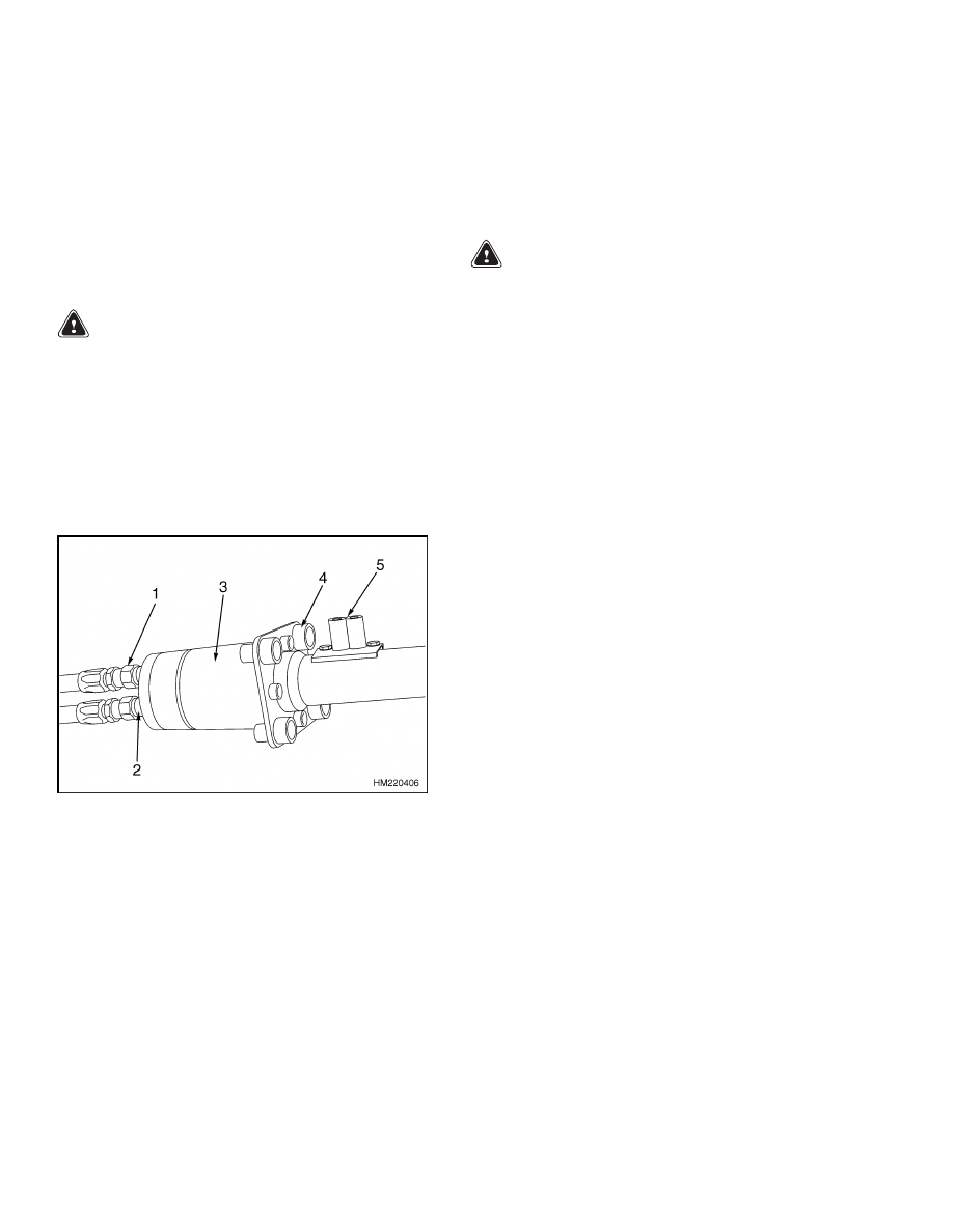
9.
Disconnect the hydraulic hoses at the bottom of
the steering control unit. Install plugs at all hose
ports and hose ends to prevent dirt from entering
the system. See Figure 5.
1.
HYDRAULIC HOSE ENDS
2.
HOSE PORTS
3.
STEERING CONTROL UNIT
4.
SCREWS
5.
HORN SWITCH
Figure 5. Hydraulic Hose Connections
10. Remove the capscrews, lockwashers, and lock
plates that fasten the steering column to the
pivots on the lift truck. Remove the steering col-
umn from the lift truck. Make sure the electric
wires and the hydraulic hoses are not damaged
as the steering column is removed.
ASSEMBLY COMPONENTS, INSTALL
NOTE: This procedure is for the installation of all
components of the steering column assembly. Do only
those steps of the procedure necessary to install the
component you need to install.
WARNING
The hydraulic hoses MUST be connected to the
correct ports and fittings or the steering sys-
tem will not operate as expected. This opera-
tion that is not expected can cause damage or
personal injury. Connect the hoses as identi-
fied during removal.
1.
Install the steering control unit to the bracket.
Install the steering column to steering control
unit and bracket. See Figure 3.
2.
Remove plug at each hose end and port.
3.
Connect each hydraulic hose at the bottom of the
steering control unit. Make sure each hydraulic
hose is connected to the correct port as identified
during removal. Repeat Step 1 through Step 3
until all hydraulic hoses are connected to their
ports. See Figure 5.
4.
Connect the wire connector and install the two
capscrews that hold the steering sensor to the
steering column.
5.
Install the steering wheel and large hex nut.
Tighten the large hex nut to 40 to 54 N•m (30 to
40 lbf ft). Connect the wire at the horn button
and install the horn button.
6.
Identify the corresponding contact and electrical
wire to each directional switch. Install the direc-
tional switch to the housing of the steering col-
umn. Install screws and shift lever assembly to
steering column. See Figure 4.
7.
If removed, install the wires on the key switch
that were identified during removal. Install the
key switch.
8.
Identify each horn wire to the horn switch. In-
stall each horn wire to the horn switch. Using
two plastic rivets install the horn switch into the
steering shaft.
6
1600 SRM 1054
Power Steering Motor and Pump
9.
If removed, connect the wire connectors on the
direction switch that were identified during re-
moval. Install the direction switch in the housing
and install the large nut, dust cover, and handle.
See Figure 4.
10. Install column tilt lever.
11. Connect the wire connectors at the bottom of the
steering column. Install the upper and lower ac-
cess covers on the steering column. See Figure 3.
12. Lower the steering column to the DOWN posi-
tion. Remove DO NOT CONNECT BATTERY
tag from truck battery connector. Connect the
battery and operate the steering system to check
for correct operation and leaks.
Power Steering Motor and Pump
DESCRIPTION
NOTE: See also the section Hydraulic System
1900 SRM 559 for additional information for the
power steering pump. The steering motor and pump
assembly are mounted behind the battery compart-
ment on J2.00-3.20XM (J40-60Z) (A416).
Under
the floor boards on E2.00-3.20XM (E45-65Z) (G108),
V30ZMD (D210),
and E3.50-5.50XL (E70-120Z)
(D098) lift truck models, and under the battery
tray on E1.50-2.00XM (E25-35Z,E40ZS) (E114). See
Figure 6
The power steering motor and pump operate as de-
scribed in Description in the front of this manual.
See Figure 7.
REMOVE
WARNING
Make sure the blocks or stands have enough
capacity to hold the lift truck. Use additional
blocks next to the tires as necessary to prevent
movement of the lift truck.
NOTE: To remove the steering motor and pump
from the E2.00-3.20XM (E45-65Z) (G108), V30ZMD
(D210), and E3.50-5.50XL, E4.50XLS (E70-120Z,
E100ZS) (D098) the floor boards must be removed,
and on the E1.50-2.00XM (E25-35Z,E40ZS) (E114)
the battery and battery tray must be removed See
Figure 6.
NOTE: Put the lift truck on blocks as described in
the Operating Manual or in the section Periodic
Maintenance 8000 SRM 1060. To remove the steer-
ing motor and pump from the J2.00-3.20XM (J40-
60Z) (A416) the left steer wheel and fender shield
must be removed. See Figure 6.
1.
Turn the key to the OFF position, unplug bat-
tery, and discharge capacitors by honking horn.
Remove the left steer wheel.
NOTE: Step 2, Step 3, Step 4, Step 5, and Step 6 are
used on J2.00-3.20XM (J40-60Z) lift trucks.
2.
Remove the left side steer tire and wheel. See
the section Steering Axle 1600 SRM 316 for the
procedures.
3.
Remove the fender shield that is located above
the steer wheel on the left side.
WARNING
Never put tools or other metal objects on the
battery. Metal on the battery can cause a short
circuit and possible damage or injury.
4.
Open the hood and install a cardboard or plywood
cover on the top of the battery to prevent acciden-
tal short circuits.
5.
Remove the cover panel from the left side of the
battery.
6.
Remove the cover from the top of the counter-
weight.
7.
On E1.50-2.00XM (E25-35Z, E40ZS), E2.00-
3.20XM (E45-65Z), and E3.50-5.50XL, E4.50XLS
(E70-120Z, E100ZS), remove the floor boards.
8.
Remove the suction hose at the pump. Quickly
put plugs in the end of the hose and the pump
port to keep oil from draining and dirt from en-
tering the system.
9.
Disconnect the pressure hose from the steering
pump. Install a plug at the fitting for the hose
and the pump port.
7
Power Steering Motor and Pump
1600 SRM 1054
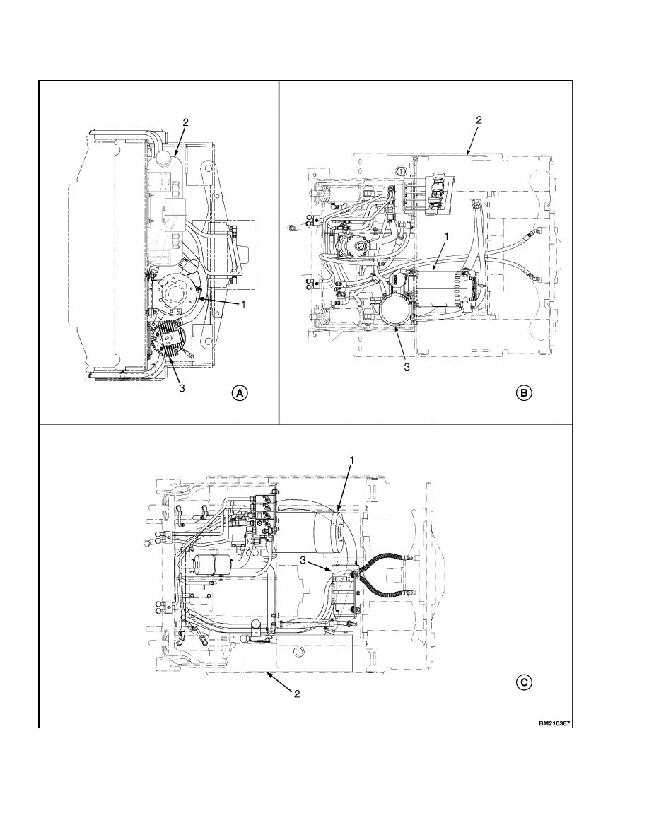
Figure 6. Steering Motor And Pump Location
8
1600 SRM 1054
Power Steering Motor and Pump
Legend for Figure 6
NOTE: TOP VIEW SHOWN
A. J2.00-3.20XM (J40-60Z) (A416)
B. E2.00-3.20XM (E45-65Z) (G108), V30ZMD (D210), AND E3.50-5.50XL, E4.50XLS (E70-120Z, E100ZS)
(D098)
C. E1.50-2.00XM (E25-35Z,E40ZS) (E114)
1.
DC HYDRAULIC MOTOR*
2.
HYDRAULIC TANK
3.
STEERING MOTOR
*LIFT TRUCK MODELS V30ZMD (D210) ARE EQUIPPED WITH A AC HYDRAULIC MOTOR ONLY.
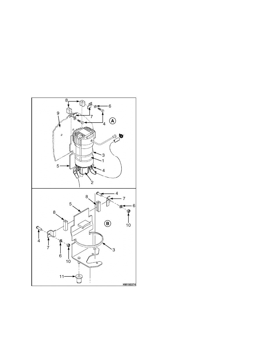
Figure 7. Steering Pump and Motor
Legend for Figure 7
A. STEERING MOTOR AND PUMP MOUNTING
BRACKET AND HARDWARE FOR
J2.00-3.20XM (J40-60Z) (A416), E1.50-2.00XM
(E25-35Z,E40ZS) (E114), E2.00-3.20XM
(E45-65Z) (G108), AND V30ZMD (D210) TRUCKS
SHOWN
B. STEERING MOTOR AND PUMP MOUNTING
BRACKET AND HARDWARE FOR E3.50-5.50XL,
E4.50XLS (E70-120Z, E100ZS) (D098) TRUCKS
SHOWN
1.
STEERING MOTOR
2.
STEERING PUMP
3.
METAL STRAP
4.
CAPSCREW
5.
BRACKET
WELDMENT
6.
WASHER
7.
BRACKET
8.
RUBBER CHANNEL
9.
TRUCK FRAME
10. NUT
11. GROMMET
10. Attach identification tags on all electrical cables.
Disconnect the cables from the pump motor.
11. Install a sling around the steering pump and
motor assembly. Connect a crane to the sling
and raise the crane so that it supports the
assembly.
The pump and motor assembly
weighs approximately 13.6 kg (30 lb) or more
for lift truck models J2.00-3.20XM (J40-60Z)
(A416), E1.50-2.00XM (E25-35Z,E40ZS) (E114),
E2.00-3.20XM (E45-65Z) (G108), and V30ZMD
(D210) and 18.5 kg (41 lb) for lift truck models
E3.50-5.50XL, E4.50XLS (E70-120Z, E100ZS)
(D098).
12. Remove the capscrews that fasten the mounting
bracket to the lift truck frame.
13. Remove the pump and motor as an assembly.
14. Make a note of the position of the inlet and outlet
ports of the pump for correct alignment to the
motor during assembly. Remove the capscrews
that fasten the pump to the motor and carefully
remove the pump. Remove the O-rings between
the motor and the pump. See Figure 1.
9

Power Steering Motor and Pump
1600 SRM 1054
DISASSEMBLE
The power steering motor cannot be disassembled. It
must be replaced as an entire unit.
INSTALL
1.
Install a new O-ring between the motor and the
pump.
2.
Install the pump on the motor. Make sure the
pump shaft correctly engages the motor shaft.
3.
Attach the motor to the mounting bracket. Make
sure the motor is correctly aligned on the mount-
ing bracket.
4.
Attach a sling around the motor. Position the
sling so it passes through the area where the
steering motor mounts. Attach a crane to the
sling, and carefully lift the pump motor assem-
bly into position.
5.
Raise the motor into position. Install the mount-
ing bolts that attach the mounting bracket to the
lift truck frame.
6.
Attach all electrical cables to the motor as
marked during removal.
NOTE: Tighten the connections for power cables at
M6 terminals to 18 to 22 N•m (159 to 195 lbf in).
On lift truck models E3.50-5.50XL, E4.50XLS (E70-
120Z, E100ZS) (D098) tighten M6 terminals to 6.5 to
7.0 N•m (57.5 to 62.0 lbf in).
7.
Attach the pressure hose to the pump.
8.
On
E1.50-2.00XM
(E25-35Z,E40ZS),
E2.00-
3.20XM (E45-65Z), and E3.50-5.50XL, E4.50XLS
(E70-120Z, E100ZS), install the floor boards.
NOTE: Step 9, Step 10, Step 11, Step 12, Step 13,
and Step 14 are used on J2.00-3.20XM (J40-60Z) lift
trucks.
9.
Attach the suction hose to the pump.
10. Install the cover on the counterweight.
11. Install the cover panel on the left side of the
truck.
12. Install the fender shield.
13. Carefully slide the wheel onto the spindle. In-
stall the outer bearing cone.
14. Install the castle nut. Tighten the castle nut to
68 N•m (50 lbf ft). Back off one quarter turn and
torque the castle nut to 3 N•m (25 lbf in). Insert
and bend one prong of cotter pin.
POWER STEERING PUMP, REPAIR
Seals that are worn or damaged are the most common
cause of pump repair. The pump bearings, gears, and
shafts also wear. Most service persons do not repair
a worn pump. The cost of repairs can be greater than
the cost of a new pump. The seals can be replaced in
the power steering pump. Replace a power steering
pump that is worn or damaged.
The power steering pump is a single-section gear
pump that is fastened to the power steering motor.
See Figure 8. The inlet (suction port) of the pump
is connected to the hydraulic tank with a hydraulic
hose. Bushings at each side of each gear are the
bearings for the gearshafts. The bushings also have
passages for the oil flow to the pump outlet and for
lubrication. Seals prevent leaks between sections of
the pump housing. A coupling is connected between
the motorshaft and the pump shaft.
When the pump is installed on the motor, use a new
O-ring between the pump and the motor housings.
Seal, Replace
NOTE: If the pump is held in a vise for disassem-
bly, do not cause distortion of the pump body. Use
a vise with soft jaws or blocks of soft wood between
the pump body and the jaws of the vise.
Make an identification of the location of the parts and
seals during disassembly. Similar parts can cause
errors during assembly. Identification of the parts
can be difficult if the parts are mixed.
1.
Remove the four capscrews that hold the pump
together. Two of the capscrews are through bolts
and fasten to the end plate of the motor.
2.
Carefully remove the end covers and remove the
seals and O-rings.
3.
Carefully press the gear bearing and gear assem-
blies from the pump body.
10
1600 SRM 1054
Power Steering Motor and Pump
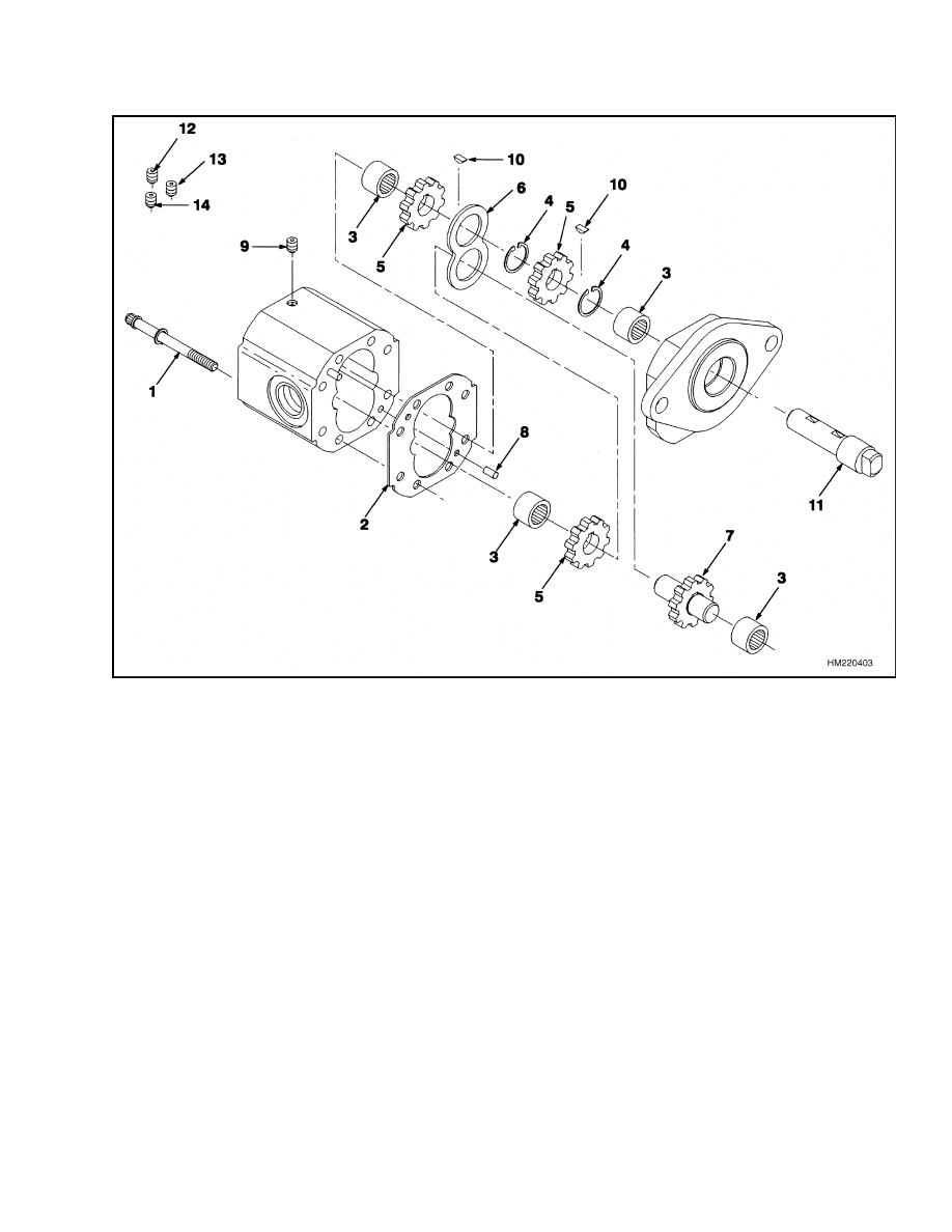
1.
SCREW
2.
GASKET KIT
3.
NEEDLE BEARING
4.
SNAP RING
5.
GEAR
6.
SPACER PLATE
7.
IDLER SHAFT KIT
8.
PIN
9.
PLUG
10. KEY
11. SHAFT
12. PLUG (PLASTIC)
13. PLUG (PLASTIC)
14. PLUG (STEEL)
Figure 8. Power Steering Pump
NOTE: Some pump bodies will show marks caused by
gears as the gears rotate against the pump body. The
small clearances between the parts cause the gears
to leave the marks. These marks do not always indi-
cate that the pump is worn or damaged. If the pump
will not supply the volume and pressure shown in the
specifications, then the pump must be repaired or re-
placed.
4.
Inspect the gear assemblies, the gear bearings,
and the pump body for wear or damage.
5.
Clean the internal parts of the pump. Use hy-
draulic oil to lubricate the parts as they are in-
stalled into the pump. Install new seals in the
bushings.
6.
Install the gears and bushings in the pump body.
7.
Install new O-rings, seal rings, and dowel pin
into the end cover of the pump with the relief
valve. See Figure 8 for the arrangement.
8.
Install new O-rings, seal rings, and dowel pin
into the other end cover with the flange. Install
this end cover onto the pump.
11
Steering Pressure Check
1600 SRM 1054
9.
Check that all of the parts are in the correct posi-
tion, and install the four capscrews. Tighten the
capscrews to 34 to 40 N•m (25 to 30 lbf ft).
10. Install a new O-ring on the flange to seal against
the end plate of the motor.
Steering System Air Removal
If there is air in the hydraulic lines of the steering
system, the operation will not be constant. Rotate
the steering wheel from stop to stop several times to
remove the air from the steering system. If the air
cannot be removed from the steering system, check
for leaks at the power steering pump. Check for a
loose fitting or a leak in the intake manifold. If the
O-ring or the oil seal between the power steering
motor and pump has damage, air will enter the hy-
draulic system.
Steering Pressure Check
Do the following procedure to connect a 20 MPa
(3000 psi) gauge:
1.
Remove the cap of the pressure check fitting in
the steering line under the floor plate and near
the center of the cowl. See Figure 1 and Figure 9.
2.
The hydraulic oil must be at operating tempera-
ture 54 to 66 C (130 to 150 F)
3.
Operate the power steering pump and steering
for a complete turn. The maximum pressure for
each lift truck covered in this manual is:
• J2.00-3.20XM (J40-60Z) (A416) 9.40 MPa
(1342 psi)
• E1.50-2.00XM
(E25-35Z,
E40ZS)
(E114)
6.05 MPa (864 psi)
• E2.00-3.20XM
(E45-65Z)
(G108)
and
V30ZMD (D210) 9.00 MPa (1286 psi)
• E3.50-5.50XL,
E4.50XLS
(E70-120Z,
E100ZS) (D098) 10.7 MPa (1550 psi)
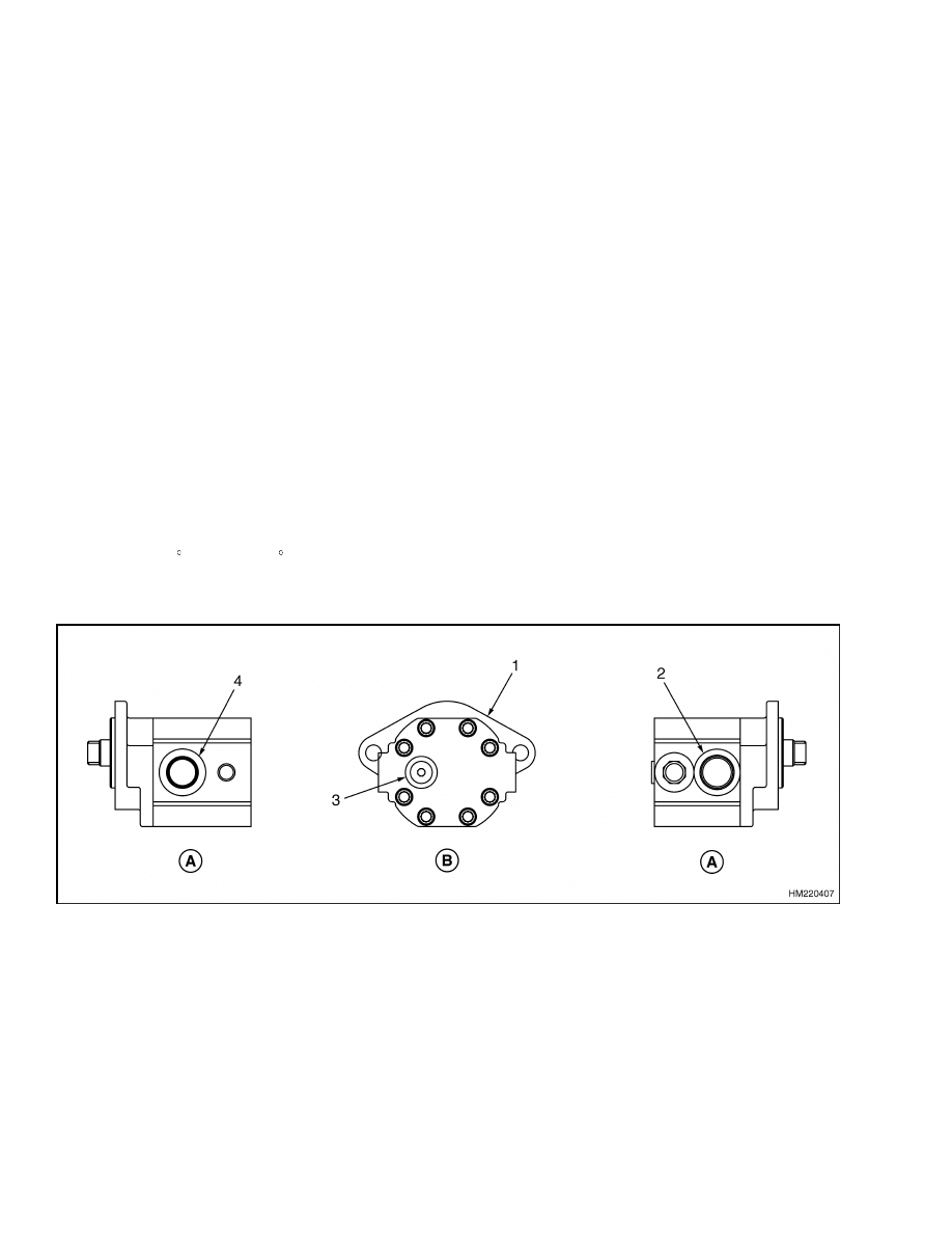
A. TOP VIEW
B. BOTTOM VIEW
1.
POWER STEERING PUMP
2.
INLET PORT
3.
PRESSURE PORT
4.
OUTLET PORT
Figure 9. Steering System Pressure Check
12

1600 SRM 1054
Steering Motor Circuits Check
4.
If the pressure is less than the minimum pres-
sure for the lift truck, check that the power steer-
ing pump is not worn or damaged. If the power
steering pump is worn or damaged, replace the
steering pump. The minimum pressure for each
lift truck is:
• J2.00-3.20XM (J40-60Z) (A416) 8.70 MPa
(1242 psi)
• E1.50-2.00XM
(E25-35Z,
E40ZS)
(E114)
5.54 MPa (792 psi)
• E2.00-3.20XM
(E45-65Z)
(G108)
and
V30ZMD (D210) 8.50 MPa (1214 psi)
• E3.50-5.50XL,
E4.50XLS
(E70-120Z,
E100ZS) (D098) 10.0 MPa (1450 psi)
5.
When the pressure checks are complete, return
the steering system to normal operation.
Steering Motor Circuits Check
1.
Raise the drive wheels as described in the Op-
erating Manual or the section Periodic Main-
tenance 8000 SRM 1060 for lift truck mod-
els J2.00-3.20XM (J40-65Z) (A416), V30ZMD
(D210), E1.50-2.00XM (E25-35Z, E40ZS) (E114),
and E2.00-3.20XM (E45-65Z) (G108) or sec-
tion Periodic Maintenance 8000 SRM 1201
for lift truck models E3.50-5.50XL, E4.50XLS
(E70-120Z, E100ZS) (D098).
NOTE: Pump motor will not stop operating after
steering wheel stops moving.
2.
Visually inspect that the steering contactor and
main contactor close at the same time.
a. If steer contactor does not close. Make sure
the seat switch is working correctly.
b. Check continuity of steer contactor coil. If
steer contactor coil is open, replace steer con-
tactor.
c.
Check battery positive on wire 3C. See the
section Electrical Diagrams,
AC Mo-
tor Control System 8000 SRM 1059 for
lift truck models J2.00-3.20XM (J40-65Z)
(A416),
V30ZMD (D210),
E1.50-2.00XM
(E25-35Z, E40ZS) (E114), and E2.00-3.20XM
(E45-65Z) (G108) or section Diagrams, AC
Motor Control System 8000 SRM 1203 for
lift truck models E3.50-5.50XL, E4.50XLS
(E70-120Z, E100ZS) (D098) for more infor-
mation. Also, check continuity of wiring to
the Master Controller.
3.
If the steer contactor closes. See the section Con-
trol and Power Fuse Check, and check fuse 4 and
7.
4.
Remove steer column covers and look for LED
to light when steer contactor is closed and the
steering wheel is turned.
a. If the LED does not light, unplug connec-
tor and check for battery voltage across
wires 11D and 13X. See the section Elec-
trical Diagrams,
AC Motor Control
System 8000 SRM 1059 for lift truck models
J2.00-3.20XM (J40-65Z) (A416), V30ZMD
(D210),
E1.50-2.00XM (E25-35Z, E40ZS)
(E114), and E2.00-3.20XM (E45-65Z) (G108)
or section Diagrams, AC Motor Control
System 8000 SRM 1203 for lift truck mod-
els
E3.50-5.50XL,
E4.50XLS
(E70-120Z,
E100ZS) (D098) for more information. If bat-
tery voltage is present, replace steer sensor.
b. If LED does not light, check continuity
of steering signal wire.
See the section
Electrical Diagrams, AC Motor Control
System 8000 SRM 1059 for lift truck models
J2.00-3.20XM (J40-65Z) (A416), V30ZMD
(D210),
E1.50-2.00XM (E25-35Z, E40ZS)
(E114), and E2.00-3.20XM (E45-65Z) (G108)
or section Diagrams, AC Motor Control
System 8000 SRM 1203 for lift truck mod-
els
E3.50-5.50XL,
E4.50XLS
(E70-120Z,
E100ZS) (D098) for more information. First,
check wire 61 in the main harness between
the steer sensor connector and steer motor
connector. Second, check continuity between
wire 60E at the motor and wire 60A at the
power steering contactor.
5.
With the steering contactor closed, check for
battery voltage at steering motor terminals. If
voltage is not present, check continuity of power
leads.
6.
Unplug the two-pin connector at the steering mo-
tor. The steer motor should be running at full
RPMs. If the motor is not running at full RPMs,
the motor needs to be replaced.
13

Troubleshooting
1600 SRM 1054
Troubleshooting
PROBLEM
POSSIBLE CAUSE
PROCEDURE OR ACTION
The steering wheels do not
move
when
the
steering
wheel is turned.
The oil level is low or there is no oil
in the tank.
Fill tank to the correct level. Check
for leaks.
The steering control unit is dam-
aged.
Repair or install new control unit.
No oil flow from the steering control
unit to the steering cylinder.
Repair or install new components.
Check for leaks.
The sleeve and spool in the control
unit will not move.
Install new components.
Steer hoses not connected or have
damage.
Check for leaks.
Tighten connec-
tions.
Install new components as
necessary.
Slow or difficult steering.
Relief valve for the steering system
is not adjusted correctly.
Adjust or install new relief valve.
Low oil pressure from the Steer
pump.
Check for restrictions.
See Trou-
bleshooting Chart, Hydraulic Sys-
tem.
Seal in the steering cylinder has a
leak.
Repair cylinder. Install new seal or
new cylinder.
Steer lines are too small or have re-
strictions.
Remove restrictions. Install larger or
new hydraulic lines.
Steering control unit is worn, not as-
sembled correctly, or has damage.
Repair or install new control unit.
Steering wheel turns the
tires in the wrong direction.
The hydraulic lines are not con-
nected correctly at the steering
cylinder or at the steering control
unit.
Connect lines correctly. Remove air
from the system.
The steering operation is not
smooth.
The oil level in the tank is low.
Fill tank to the correct level. Check
for leaks.
Air was not removed after repair to
the hydraulic system.
Remove air from the system.
The hydraulic pump is leaking at the
inlet.
Fix leaks. Remove air from the sys-
tem.
14

1600 SRM 1054
Troubleshooting
PROBLEM
POSSIBLE CAUSE
PROCEDURE OR ACTION
The pump motor will not
stop operating after steering
wheel stops turning.
See Steering Motor Circuits Check.
The power steering pump
makes noise that is not nor-
mal.
There is not enough oil in hydraulic
tank.
Fill the tank to the correct level.
Check for leaks.
Air is entering the system at the in-
let side of the pump.
Repair the leaks.
The power steering motor
does not operate when the
steering wheel is turned.
See Steering Motor Circuits Check.
15

NOTES
____________________________________________________________
____________________________________________________________
____________________________________________________________
____________________________________________________________
____________________________________________________________
____________________________________________________________
____________________________________________________________
____________________________________________________________
____________________________________________________________
____________________________________________________________
____________________________________________________________
____________________________________________________________
____________________________________________________________
____________________________________________________________
____________________________________________________________
____________________________________________________________
____________________________________________________________
____________________________________________________________
____________________________________________________________
____________________________________________________________
16


TECHNICAL PUBLICATIONS
1600 SRM 1054
7/05 (3/05)(5/04)(4/04)(11/03)(3/03) Printed in United Kingdom
Document Outline
- toc
Wyszukiwarka
Podobne podstrony:
1459370 1600SRM0720 (07 2005) UK EN
1534732 0620SRM1053 (07 2005) UK EN
1534735 2200SRM1056 (07 2005) UK EN
1459370 1600SRM0720 (07 2005) UK EN
897953 1600SRM0639 (03 2005) UK EN
1596602 0100SRM1200 (07 2005) UK EN
1565582 1600SRM1114 (04 2005) UK EN
1554634 2200SRM1078 (07 2005) UK EN
1468474 2200SRM0756 (07 2005) UK EN
1580512 1600SRM1133 (05 2005) UK EN
1596605 8000SRM1203 (07 2005) UK EN
1580519 2200SRM1131 (07 2005) UK EN
897097 1600SRM0316 (04 2005) UK EN
1556364 0620SRM1098 (07 2005) UK EN
więcej podobnych podstron