AC MOTOR REPAIR
E1.50-2.00XM (E25-35Z, E40ZS) [E114];
E2.00-3.20XM (E45-65Z) [G108]; V30ZMD [D210];
E3.50-5.50XL, E4.50XLS
(E70-120Z, E100ZS) [D098]
PART NO. 1556364
620 SRM 1098

SAFETY PRECAUTIONS
MAINTENANCE AND REPAIR
• When lifting parts or assemblies, make sure all slings, chains, or cables are correctly
fastened, and that the load being lifted is balanced. Make sure the crane, cables, and
chains have the capacity to support the weight of the load.
• Do not lift heavy parts by hand, use a lifting mechanism.
• Wear safety glasses.
• DISCONNECT THE BATTERY CONNECTOR before doing any maintenance or repair
on electric lift trucks. Disconnect the battery ground cable on internal combustion lift
trucks.
• Always use correct blocks to prevent the unit from rolling or falling. See HOW TO PUT
THE LIFT TRUCK ON BLOCKS in the Operating Manual or the Periodic Mainte-
nance section.
• Keep the unit clean and the working area clean and orderly.
• Use the correct tools for the job.
• Keep the tools clean and in good condition.
• Always use HYSTER APPROVED parts when making repairs. Replacement parts
must meet or exceed the specifications of the original equipment manufacturer.
• Make sure all nuts, bolts, snap rings, and other fastening devices are removed before
using force to remove parts.
• Always fasten a DO NOT OPERATE tag to the controls of the unit when making repairs,
or if the unit needs repairs.
• Be sure to follow the WARNING and CAUTION notes in the instructions.
• Gasoline, Liquid Petroleum Gas (LPG), Compressed Natural Gas (CNG), and Diesel fuel
are flammable. Be sure to follow the necessary safety precautions when handling these
fuels and when working on these fuel systems.
• Batteries generate flammable gas when they are being charged. Keep fire and sparks
away from the area. Make sure the area is well ventilated.
NOTE: The following symbols and words indicate safety information in this
manual:
WARNING
Indicates a condition that can cause immediate death or injury!
CAUTION
Indicates a condition that can cause property damage!

AC Motor Repair
Table of Contents
TABLE OF CONTENTS
General ...............................................................................................................................................................
AC Motor Repair ................................................................................................................................................
Disassemble ...................................................................................................................................................
Assemble ........................................................................................................................................................
Troubleshooting..................................................................................................................................................
This section is for the following models:
E1.50-2.00XM (E25-35Z, E40ZS) [E114];
E2.00-3.20XM (E45-65Z) [G108];
V30ZMD [D210];
E3.50-5.50XL, E4.50XLS (E70-120Z, E100ZS) [D098]
©2005 HYSTER COMPANY
i

"THE
QUALITY
KEEPERS"
HYSTER
APPROVED
PARTS
620 SRM 1098
AC Motor Repair
General
This section describes the disassembly, assembly,
and inspection procedures and checks for malfunc-
tions of AC motors.
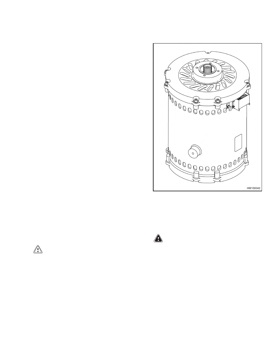
AC traction motors and AC hydraulic pump motors
are similar in design. See Figure 1. The AC hy-
draulic pump and AC steering pump motors are a
smaller version of the AC traction motor. Disassem-
bly and repair of these motors are similar.
Figure 1. AC Traction Motor V30ZMD (D210)
and E2.00-3.20XM (E45-65Z) (G108) Models
Shown
AC Motor Repair
DISASSEMBLE
CAUTION
The bearings and seal on the AC traction motor
are serviceable parts, while the only service-
able parts on the AC hydraulic pump motor are
the bearings. Be careful to not damage bear-
ings when replacing.
NOTE: When replacing one bearing, it is strongly rec-
ommended to replace both bearings and the seal of
the AC traction motor.
1.
Remove motor from the lift truck. See the Frame
SRM for your lift truck model for removal infor-
mation.
WARNING
The AC hydraulic pump motor can weigh as
much as113 kg (250 lb) and the AC traction mo-
tor can weigh as much as204 kg (450 lb). To pre-
vent injury, use a lifting device capable of lift-
ing the assembly.
2.
Screw lifting eye into the threaded hole in the
end of the rotor shaft, and connect a chain to lift-
ing eye. Attach approved lifting device and lift
motor.
3.
Place motor on level blocks on a flat surface with
drive end pointing down. Remove approved lift-
ing device and lifting eye. See Figure 1.
4.
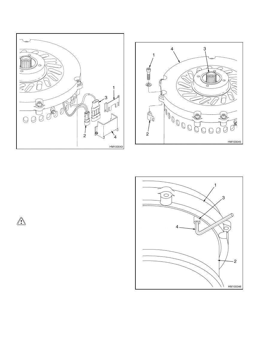
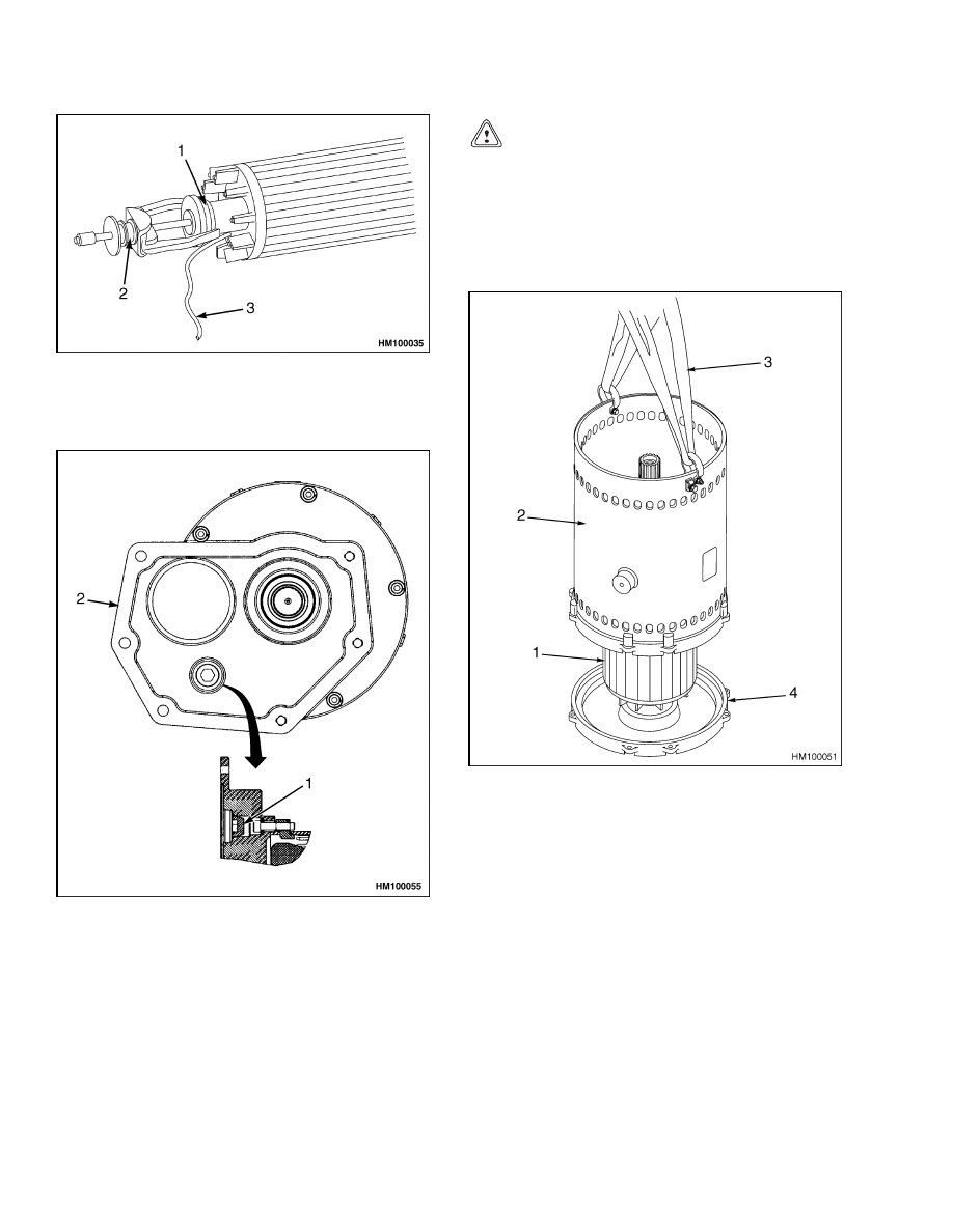
Remove connector cover. See Figure 2.
1
AC Motor Repair
620 SRM 1098
1.
MOUNTING BRACKET
2.
TEMPERATURE SENSOR
3.
ENCODER BEARING CONNECTOR
4.
CONNECTOR COVER
Figure 2. Connector Cover
5.
Remove connectors from mounting bracket. See
Figure 2.
6.
Remove screws and retaining nuts from the end
bell. See Figure 3.
CAUTION
Do not rotate the end bell. Lift end bell straight
up enough to separate the bearing. If the end
bell is pulled or lifted too high, damage will oc-
cur to the encoder wire.
7.
With a rubber mallet, gently tap under the end
bell and lift end bell straight up.
8.
Support end bell with four small blocks and re-
move hex socket screws that attach air guide to
the end bell. See Figure 4.
9.
Remove end bell by lifting it straight up.
10. Pull rubber wire mount out of the stator. See
11. Separate encoder wire and temperature sensor
wire from the rubber wire mount. See Figure 6.
12. Remove the air guide. See Figure 7.
1.
SCREW
2.
RETAINING NUT
3.
ROTOR SHAFT
4.
END BELL
Figure 3. Removing Screws and Retaining
Nuts From End Bell
1.
END BELL
2.
AIR GUIDE
3.
HEX SOCKET SCREW
4.
HEX SOCKET SCREW WRENCH
Figure 4. Hex Socket Screws Removal
2
620 SRM 1098
AC Motor Repair
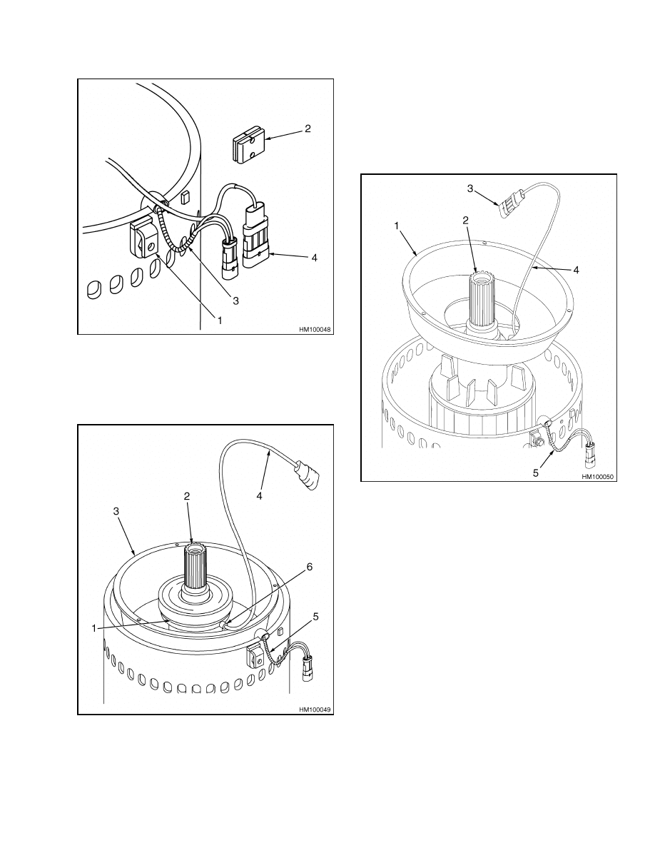
1.
POWER TERMINAL
2.
RUBBER WIRE MOUNT
3.
TEMPERATURE SENSOR WIRE
4.
ENCODER BEARING CONNECTOR
Figure 5. Rubber Wire Mount Removal
Figure 6. Separated Encoder Wire From
Rubber Mount
Legend for Figure 6
1.
ENCODER BEARING
2.
ROTOR SHAFT
3.
AIR GUIDE
4.
ENCODER BEARING WIRE
5.
TEMPERATURE SENSOR WIRE
6.
ENCODER BEARING TANG
1.
AIR GUIDE
2.
ROTOR SHAFT
3.
ENCODER BEARING CONNECTOR
4.
ENCODER BEARING WIRE
5.
TEMPERATURE SENSOR WIRE
Figure 7. Air Guide Removal
NOTE: Before removing the encoder bearing, note its
orientation and install the new encoder bearing in
the same orientation.
13. Using a bearing puller, remove encoder bearing.
See Figure 8.
NOTE: Perform Step 14 for E1.50-2.00XM (E25-35Z,
E40ZS) (E114) model only.
14. Remove the 3/4 inch hex socket plug from the end
bell. See Figure 9.
3
AC Motor Repair
620 SRM 1098
1.
ENCODER
BEARING
2.
BEARING PULLER
3.
ENCODER WIRE
Figure 8. Bearing Removal
1.
3/4-INCH HEX SOCKET PLUG
2.
END BELL
Figure 9. End Bell E1.50-2.00XM (E25-35Z,
E40ZS) (E114)
15. Remove screws and retaining nuts from the drive
end bell.
CAUTION
To prevent damage to the encoder wire, make
sure the encoder wire is out of the way when
lifting stator.
16. Attach approved lifting device to the stator, and
slowly lift stator straight up from the rotor and
drive end bell. See Figure 10.
1.
ROTOR
2.
STATOR
3.
APPROVED LIFTING DEVICE
4.
DRIVE END BELL
Figure 10. Lifting of Stator V30ZMD (D210)
and E2.00-3.20XM (E45-65Z) (G108) Models
Shown
NOTE: On the hydraulic pump motors there is a sec-
ond air guide attached to the drive end bell. Remove
screws from the second air guide so you are able to
move the second air guide for access to the snap ring.
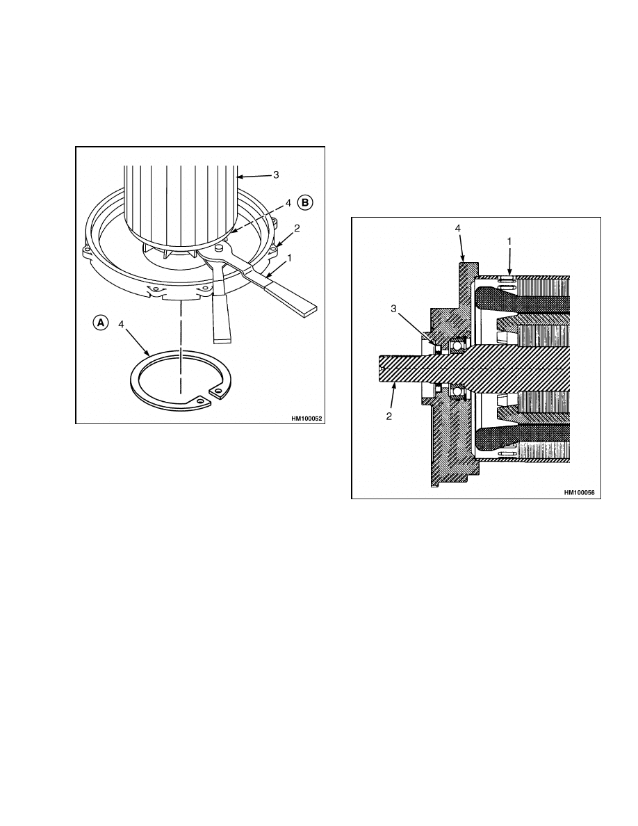
NOTE: On older lift truck models, the snap ring is
between the rotor and drive end of end bell. You will
need to feel with your fingers where the snap ring
is located and attach the snap ring pliers. See Fig-
ure 11.
4
620 SRM 1098
AC Motor Repair
NOTE: On newer lift truck models, the snap ring is
located in the drive end of the end bell. See Figure 11.
17. Remove snap ring. For older lift truck models,
use snap ring pliers. See Figure 11.
A. LOCATION OF SNAP RING, NEWER LIFT
TRUCK MODELS
B. LOCATION OF SNAP RING, OLDER LIFT TRUCK
MODELS
1.
SNAP RING PLIERS
2.
DRIVE END BELL
3.
ROTOR
4.
SNAP RING
Figure 11. Snap Ring Removal V30ZMD (D210)
and E2.00-3.20XM (E45-65Z) (G108) Models
Shown
18. Screw lifting eye into the threaded hole in the
end of the rotor shaft. Attach approved lifting
device and lift rotor straight up from the drive
end bell.
19. Using a bearing puller, remove bearing from
drive end of rotor shaft.
20. Remove snap ring from shaft.
21. Using a seal driver, remove drive shaft seal from
end bell.
ASSEMBLE
NOTE: Perform Step 1 for E1.50-2.00XM (E25-35Z,
E40ZS) (E114) model only.
1.
Lubricate the drive end bell seal shaft with mul-
tipurpose grease using 2 to 4 percent molybde-
num disulfide. See Figure 12.
1.
TRACTION MOTOR (SHOWN)
2.
ROTOR ASSEMBLY
3.
DRIVE END BELL SEAL SHAFT
4.
DRIVE END HOUSING
Figure 12. Lubrication of Seal Shaft
2.
Using a seal driver, install drive shaft seal, with
lip seal towards the motor, in end bell.
3.
On older lift truck models, place snap ring on
rotor shaft with chamfered side toward the rotor.
See Figure 11.
4.
Install the bearing on the drive end of the rotor
shaft using a bearing driver and arbor press.
5
AC Motor Repair
620 SRM 1098
CAUTION
To avoid damage to the encoder bearing elec-
tronics, use a bearing drive and arbor press.
NOTE: The encoder bearing must be oriented as
noted during removal.
5.
Using a bearing driver and arbor press, install
encoder bearing as noted during removal.
6.
Attach lifting eye and lift rotor with approved
lifting device. Lower rotor into drive end bell.
Make sure bearing is fully seated against drive
end bell.
7.
On older lift truck models, use snap ring pliers
and install snap ring into groove. For newer lift
truck models, install snap ring in drive end of the
end bell. See Figure 11.
8.
Remove approved lifting device and lifting eye
from rotor.
CAUTION
To avoid damage to the encoder wire, make
sure the encoder wire is out of the way when
lowering stator onto drive end bell.
9.
Use approved lifting device and lift stator.
NOTE: Make sure holes for retaining nuts in stator
are aligned with the holes for the retaining bolts in
the drive end bell.
10. Lower stator straight onto drive end bell. See
11. Remove approved lifting device from stator.
12. Attach retaining bolts and nuts into stator and
the drive end bell. Tighten retaining bolts and
nuts to 25 to 30 N•m (221 to 265 lbf in). See
Figure 3.
NOTE: Perform Step 13 for E1.50-2.00XM (E25-35Z,
E40ZS) (E114) model only.
13. Install the 3/4 inch hex socket plug into the end
bell to prevent oil leakage. See Figure 9.
14. Place encoder wire through air guide and lower
air guide onto rotor shaft.
15. Place encoder wire and temperature sensor wire
back into the rubber wire mount.
16. Place rubber wire mount back into stator.
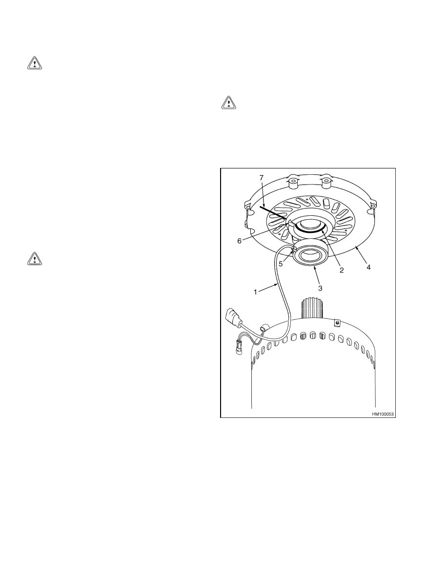
NOTE: Make sure the spring washer is installed in
the end bell. See Figure 13.
CAUTION
To prevent damage to the encoder bearing, en-
sure encoder wire is inserted in encoder wire
slot when air guide is attached to the end bell.
17. Insert encoder wire in the end bell slot and attach
air guide to end bell. See Figure 13.
1.
ENCODER WIRE
2.
SPRING WASHER
3.
ENCODER
BEARING
4.
END BELL
5.
ENCODER
BEARING TANG
6.
ENCODER TANG
SLOT
7.
ENCODER WIRE
SLOT
Figure 13. Alignment of Encoder Wire and
Encoder Bearing Tang in End Bell Slot
6

620 SRM 1098
Troubleshooting
CAUTION
To prevent damage to the encoder wire, line up
encoder tang slot with encoder bearing tang.
18. For proper bearing alignment, see Figure 13.
Lower the end bell straight down onto the rotor
shaft.
19. Seat end bell completely onto shaft.
20. Attach screws and retaining nuts to the end bell.
21. Attach connectors to mounting bracket and at-
tach connector cover and mounting bracket to
stator. Tighten connector cover capscrews to 3.4
to 4.0 N•m (30 to 35 lbf in). See Figure 2.
Troubleshooting
PROBLEM
POSSIBLE CAUSE
PROCEDURE OR ACTION
Truck moves slow or in a
jerky motion.
Encoder broken.
Replace encoder bearing.
Encoder wire broken.
Check and repair encoder wire or re-
place encoder bearing.
Temperature
sensor
wire
fails.
Measure resistance with ohmmeter.
Resistance should be 530 ohms at 25
C (77 F). Repair temperature sensor
wire. The temperature sensor wire
can be repaired, but the temperature
sensor cannot be repaired.
Stator wires fail.
Loss of insulation in wire.
Check resistance between winding
and case.
Resistance should be at
50,000 ohms or above.
7

NOTES
____________________________________________________________
____________________________________________________________
____________________________________________________________
____________________________________________________________
____________________________________________________________
____________________________________________________________
____________________________________________________________
____________________________________________________________
____________________________________________________________
____________________________________________________________
____________________________________________________________
____________________________________________________________
____________________________________________________________
____________________________________________________________
____________________________________________________________
____________________________________________________________
____________________________________________________________
____________________________________________________________
____________________________________________________________
____________________________________________________________
8


TECHNICAL PUBLICATIONS
620 SRM 1098
7/05 (3/05)(6/04)(11/03) Printed in United Kingdom
Document Outline
Wyszukiwarka
Podobne podstrony:
1534732 0620SRM1053 (07 2005) UK EN
1566043 0620SRM1115 (08 2005) UK EN
1459370 1600SRM0720 (07 2005) UK EN
1596602 0100SRM1200 (07 2005) UK EN
1554634 2200SRM1078 (07 2005) UK EN
1468474 2200SRM0756 (07 2005) UK EN
1596605 8000SRM1203 (07 2005) UK EN
1580519 2200SRM1131 (07 2005) UK EN
1534733 1600SRM1054 (07 2005) UK EN
1534735 2200SRM1056 (07 2005) UK EN
1566043 0620SRM1115 (08 2005) UK EN
1459370 1600SRM0720 (07 2005) UK EN
więcej podobnych podstron