AC MOTOR CONTROLLERS/DISPLAY
PANEL
DESCRIPTION, CHECKS, ADJUSTMENTS, AND
TROUBLESHOOTING
J2.00-3.20XM (J40-65Z) [A416]; V30ZMD [D210];
E1.50-2.00XM (E25-35Z, E40ZS) [E114];
E2.00-3.20XM (E45-65Z) [G108];
E3.50-5.50XL, E4.50XLS (E70-120Z, E100ZS) [D098]
PART NO. 1534735
2200 SRM 1056

SAFETY PRECAUTIONS
MAINTENANCE AND REPAIR
• When lifting parts or assemblies, make sure all slings, chains, or cables are correctly
fastened, and that the load being lifted is balanced. Make sure the crane, cables, and
chains have the capacity to support the weight of the load.
• Do not lift heavy parts by hand, use a lifting mechanism.
• Wear safety glasses.
• DISCONNECT THE BATTERY CONNECTOR before doing any maintenance or repair
on electric lift trucks. Disconnect the battery ground cable on internal combustion lift
trucks.
• Always use correct blocks to prevent the unit from rolling or falling. See HOW TO PUT
THE LIFT TRUCK ON BLOCKS in the Operating Manual or the Periodic Mainte-
nance section.
• Keep the unit clean and the working area clean and orderly.
• Use the correct tools for the job.
• Keep the tools clean and in good condition.
• Always use HYSTER APPROVED parts when making repairs. Replacement parts
must meet or exceed the specifications of the original equipment manufacturer.
• Make sure all nuts, bolts, snap rings, and other fastening devices are removed before
using force to remove parts.
• Always fasten a DO NOT OPERATE tag to the controls of the unit when making repairs,
or if the unit needs repairs.
• Be sure to follow the WARNING and CAUTION notes in the instructions.
• Gasoline, Liquid Petroleum Gas (LPG), Compressed Natural Gas (CNG), and Diesel fuel
are flammable. Be sure to follow the necessary safety precautions when handling these
fuels and when working on these fuel systems.
• Batteries generate flammable gas when they are being charged. Keep fire and sparks
away from the area. Make sure the area is well ventilated.
NOTE: The following symbols and words indicate safety information in this
manual:
WARNING
Indicates a condition that can cause immediate death or injury!
CAUTION
Indicates a condition that can cause property damage!

AC Motor Controllers/Display Panel
Table of Contents
TABLE OF CONTENTS
Description .........................................................................................................................................................
General ...........................................................................................................................................................
AC Motors ..................................................................................................................................................
Motor Controllers ......................................................................................................................................
Master Controller ......................................................................................................................................
Dash Display .............................................................................................................................................
Controller Area Network Bus (CANBus) .................................................................................................
Master Controller Checks and Adjustments ....................................................................................................
Function Settings...............................................................................................................................................
General ...........................................................................................................................................................
Function Numbers .........................................................................................................................................
Function Descriptions........................................................................................................................................
General ...........................................................................................................................................................
Function Number 1 BATTERY VOLTAGE ..............................................................................................
Function Number 2 EXTENDED SHIFT ................................................................................................
Function Number 3 ACCELERATION 1 .................................................................................................
Function Number 4 ACCELERATION 2 .................................................................................................
Function Number 5 TOP SPEED LIMIT .................................................................................................
Function Number 6 REGEN BRAKING ..................................................................................................
Function Number 7 AUTO DECELERATION ........................................................................................
Function Number 8 BDI ADJUSTMENT ................................................................................................
Function Number 9 LIFT INTERRUPT ..................................................................................................
Function Number 10 POWER STEERING TIME DELAY .....................................................................
Function Number 11 SERVICE REMINDER ..........................................................................................
Function Number 12 CUSTOM................................................................................................................
Function Number 13 PUMP SPEED 1 ....................................................................................................
Function Number 14 PUMP SPEED 2 ....................................................................................................
Function Number 15 PUMP SPEED 3 ....................................................................................................
Function Number 16 PUMP ACCELERATION ......................................................................................
Troubleshooting..................................................................................................................................................
General ...........................................................................................................................................................
Controller Status Light Emitting Diodes (LEDs) ........................................................................................
AC Master Controller................................................................................................................................
AC Motor Controllers ................................................................................................................................
Status Codes ..................................................................................................................................................
AC Motor Controllers Status Code Charts .......................................................................................................
AC Transistor Motor Controller Replacement .................................................................................................
General ...........................................................................................................................................................
General Maintenance Instructions...............................................................................................................
Special Precautions ...................................................................................................................................
Fuses ..............................................................................................................................................................
Fan Test..........................................................................................................................................................
Contactors ......................................................................................................................................................
Repair.........................................................................................................................................................
Thermal Sensors ............................................................................................................................................
Motor Controller, Replace .............................................................................................................................
Display Panel .....................................................................................................................................................
General ...........................................................................................................................................................
Premium Display Panel ............................................................................................................................
Standard Display Panel ............................................................................................................................
Display Functions and Features .......................................................................................................................
©2005 HYSTER COMPANY
i

Table of Contents
AC Motor Controllers/Display Panel
TABLE OF CONTENTS (Continued)
Key-On Initialization.....................................................................................................................................
Standard Display ...........................................................................................................................................
Premium Display ...........................................................................................................................................
Lift Truck Inspection Function .....................................................................................................................
Access to Service Functions ..........................................................................................................................
Service Functions ..........................................................................................................................................
Performance Modes .......................................................................................................................................
Battery Discharge Indication (BDI) .............................................................................................................
Hourmeter......................................................................................................................................................
Dash Display Service Menu Navigation ...........................................................................................................
General ...........................................................................................................................................................
Moving Through Menu Selections ................................................................................................................
Editing and Adding Information ..................................................................................................................
This section is for the following models:
J2.00-3.20XM (J40-65Z) [A416];
V30ZMD [D210];
E1.50-2.00XM (E25-35Z, E40ZS) [E114];
E2.00-3.20XM (E45-65Z) [G108];
E3.50-5.50XL, E4.50XLS (E70-120Z, E100ZS) [D098]
ii

2200 SRM 1056
Description
Description
GENERAL
The alternating current (AC) system consists of AC
motors, motor controller(s), a master controller, and
a dash display. The major difference between the
AC system and the direct current (DC) system is the
master controller performs many of the same func-
tions that previously were performed in the motor
controllers on the DC system.
AC Motors
The AC motors are three-phase AC induction mo-
tors. They do not include motor brushes or commuta-
tors. An AC induction motor operates on three-phase
AC power provided directly by the motor controller.
The motor’s speed is controlled by the motor con-
troller and can be changed by the frequency of the
AC power generated to the motor. A speed sensor
has been built into the rear motor bearing, which
provides feedback to the motor controller allowing
software to continually monitor motor direction and
revolutions per minute (RPMs). Using this software
feedback, the AC motor control system can provide
much better vehicle top speed control than is avail-
able with DC SEM systems.
The AC motors also have thermal sensors embedded
in the motor windings that are continuously moni-
tored by the motor controllers.
Motor Controllers
The motor controllers convert DC power from the
truck’s battery to three-phase AC power at the fre-
quencies and currents necessary to drive the respec-
tive pump and/or traction motor. Each AC induction
motor provides feedback of speed, rotation direction,
and temperature directly to the motor controller. The
two motor controllers used to power the traction mo-
tor and hydraulic pump motor are very similar. The
primary motor controller difference is in the power
output rating.
The motor controller logic board receives power from
the key switch. Power to the motors can be inter-
rupted indirectly by the key switch. The motor con-
trollers get motor speed and temperature informa-
tion directly from the motors. The motor controllers
do not get any other input from the truck. The mas-
ter controller relays speed, acceleration, and direc-
tion commands to the motor controllers.
Master Controller
The master controller is a general-purpose mi-
cro-controller for CANbus-based electric vehicles.
It contains processing power, memory resources,
analog and digital input/output (I/O) to provide the
required full-featured functionality.
The master
controller is designed to manage the traction motor
controller and optional pump motor controller, inter-
face to the operator controls, and control the vehicle
dash display.
The master controller also manages the operating
truck parameters, status codes, battery discharge
indicator (BDI) function, hourmeters, password fea-
ture, and all operator inputs. It also supplies power
to the line and power steering contactors, cooling
fans, and reverse light relay.
Dash Display
The new AC dash display is similar in appearance
to the SEM dash display and includes the same fea-
tures. In addition, the AC dash display provides ex-
panded service capabilities. The dash display also
has a password-accessible service mode that allows a
technician to change control settings and view real-
time RPM, current, temperature, and switch closure
information. Previously, a separate handset or com-
puter was required for these operations. For a com-
plete description of the display panel see the Display
Panel section of this manual.
Controller Area Network Bus (CANBus)
The motor controllers, master controller, and dash
display are connected together with a CANbus com-
munication system. A personal computer (PC) with
the appropriate ETACC service software and inter-
face cable can easily communicate with all system
nodes by simply connecting to the CANbus. A spe-
cial connector located under the dash and next to the
display is configured specifically for this purpose
1
Function Settings
2200 SRM 1056
Master Controller Checks and Adjustments
NOTE: All checks and adjustments to the master con-
troller can be done with a personal computer (PC).
A connector in the wiring harness below the display
panel can connect the PC to the CANbus system to
communicate to the master controller. Many checks
can also be done at the display panel without being
connected to a PC.
The following checks and adjustments may be made
using a PC or the dash display:
• Check the system status codes history.
• Check the state of charge of the battery.
• Check the hourmeter readings on the traction cir-
cuit and hydraulic pump controllers.
• Monitor or adjust the register values for each func-
tion as shown inTable 1, Table 2, and Table 3.
Function Settings
GENERAL
The master controller has 16 functions (parame-
ters) that can be changed to configure different lift
truck models and voltages. The function settings
are stored and used by the master controller to deter-
mine lift truck performance or other operation vari-
ables.
NOTE: Table 1, Table 2, Table 3, and Table 4 show the
default settings for each control function. The fac-
tory-settings are the recommended settings for new
units. These settings will give satisfactory perfor-
mance for most applications.
All functions can be adjusted within the permitted
range to change the lift truck operation for a spe-
cific application. Adjustment of a register to a num-
ber that is different than the factory setting is al-
lowed, but follow the instructions carefully. Adjust-
ments other than the factory settings will cause the
lift truck performance and energy consumption to
change.
FUNCTION NUMBERS
WARNING
NEVER adjust any of the function registers
without using the procedures and settings
given in this section.
The function numbers are code numbers for the dif-
ferent parameters that can be set for the master con-
troller. The PC or the dash display must be used to
adjust the parameters for the master controller.
Table 1. Factory Parameter Table -
J2.00-3.20XM (J40-65Z) (A416)
Function
Factory
Setting
72V
Factory
Setting
80V
1-BATTERY
VOLTAGE
72
80
2-EXTENDED SHIFT
ENABLED
ENABLED
3-ACCELERATION 1
40
40
4-ACCELERATION 2
7
7
5-TOP SPEED LIMIT
94
100
6-REGEN BRAKING
75
75
7-AUTO
DECELERATION
70
70
8-BDI ADJUSTMENT
30
30
9-LIFT INTERRUPT
ENABLED
ENABLED
10-PS TIME DELAY
20
20
11-SERVICE
REMINDER
0
0
12-CUSTOM
0
0
13-PUMP SPEED 1
25
25
14-PUMP SPEED 2
50
50
15-PUMP SPEED 3
95
95
16-PUMP
ACCELERATION
25
25
2
2200 SRM 1056
Function Settings
Table 2. Factory Setting Table - V30ZMD (D210), E2.00-3.20XM (E45-65Z) (G108)
Function
Factory
Setting 36V
Factory
Setting 48V
Factory
Setting 72V
Factory
Setting 80V
1-BATTERY VOLTAGE
36
48
72
80
2-EXTENDED SHIFT
ENABLED
ENABLED
ENABLED
ENABLED
3-ACCELERATION 1
40
49
46
50
4-ACCELERATION 2
5
8
6
9
5-TOP SPEED LIMIT
85
92
91
98
6-REGEN BRAKING
60
60
60
70
7-AUTO DECELERATION
65
70
70
70
8-BDI ADJUSTMENT
30
30
30
30
9-LIFT INTERRUPT
ENABLED
ENABLED
ENABLED
ENABLED
10-PS TIME DELAY
20
20
20
20
11-SERVICE REMINDER
0
0
0
0
12-CUSTOM
0
0
0
0
13-PUMP SPEED 1
25
25
25
25
14-PUMP SPEED 2
50
50
50
50
15-PUMP SPEED 3
95
95
95
95
16-PUMP ACCELERATION
25
25
25
25
Table 3. Factory Setting Table - E1.50-2.00XM (E25-35Z, E40ZS) (E114)
Function
Factory Setting
36V
Factory Setting
48V
Factory Setting
48V (Europe)
1-BATTERY VOLTAGE
36
48
48
2-EXTENDED SHIFT
ENABLED
ENABLED
ENABLED
3-ACCELERATION 1
48
66
62
4-ACCELERATION 2
7
14
10
5-TOP SPEED LIMIT
80
100
100
6-REGEN BRAKING
60
60
75
7-AUTO DECELERATION
65
70
70
8-BDI ADJUSTMENT
30
30
30
9-LIFT INTERRUPT
ENABLED
ENABLED
ENABLED
10-PS TIME DELAY
20
20
20
11-SERVICE REMINDER
0
0
0
12-CUSTOM
0
0
0
13-PUMP SPEED 1
25
25
25
3

Function Settings
2200 SRM 1056
Table 3. Factory Setting Table - E1.50-2.00XM (E25-35Z, E40ZS) (E114) (Continued)
Function
Factory Setting
36V
Factory Setting
48V
Factory Setting
48V (Europe)
14-PUMP SPEED 2
50
50
50
15-PUMP SPEED 3
95
95
95
16-PUMP ACCELERATION
25
25
25
Table 4. Factory Parameter Table - E3.50-5.50XL, E4.50XLS (E70-120Z, E100ZS) (D098)
Function
Factory Setting
36V
Factory Setting
48V
Factory Setting
80V
1-BATTERY VOLTAGE
36V
48V
80V
2-EXTENDED SHIFT
ENABLED
ENABLED
ENABLED
3-ACCELERATION 1
35
45
45
4-ACCELERATION 2
3
4
4
5-TOP SPEED LIMIT
85
100
100
6-REGEN BRAKING
65
65
65
7-AUTO DECELERATION
80
80
80
8-BDI ADJUSTMENT
30
30
30
9-LIFT INTERRUPT
ENABLED
ENABLED
ENABLED
10-PS TIME DELAY
20
20
20
11-SERVICE REMINDER
0
0
0
12-CUSTOM
0
0
0
13-PUMP SPEED 1
25
25
25
14-PUMP SPEED 2
50
50
50
15-PUMP SPEED 3
95
95
95
16-PUMP ACCELERATION
25
25
25
4

2200 SRM 1056
Function Descriptions
Function Descriptions
GENERAL
WARNING
If any of the register values are changed, the
operators must be told that the lift truck will
operate differently.
The following section contains descriptions for the
different functions.
The register setting for each
function is specific for each motor controller.
Function Number 1 BATTERY VOLTAGE
(36, 48, 72, or 80)
Function 1 is used to inform the master controller
what voltage battery is installed in the truck. The
battery choices are: 36, 48, 72, or 80.
Function Number 2 EXTENDED SHIFT
(Enable or Disable)
Function 2 enables or disables a preset motor per-
formance program in the traction motor controller.
When enabled, this function provides a balance be-
tween truck performance and battery shift life that
will meet the requirements of most applications.
Truck acceleration and top speed will vary with the
amount of load on the forks.
When disabled, truck acceleration and top speed are
determined by values set in Functions 3, 4, and 5.
If the motor and controller can deliver the power,
then the truck performance will not vary with the
amount of load on the forks or the battery state of
charge
Grade climbing speed will also improve because the
motor controller will deliver maximum current. Any
increase in performance will decrease the battery
shift life.
Function Number 3 ACCELERATION 1
(Range 0-100)
Function 3 determines the truck acceleration rate
when traction motor speed is below 1,500 rpm. The
truck will accelerate at this rate regardless of the
load on the forks, provided that the motor and con-
trol can deliver the required power.
To increase the acceleration rate above the factory
setting, Function 2 will need to be set to disabled.
To reduce the acceleration rate below the factory
setting, Function 2 may be enabled or disabled.
Any increase in performance will decrease the bat-
tery shift life.
Function Number 4 ACCELERATION 2
(Range 0-100)
Function 4 determines the truck acceleration rate
when traction motor speed is above 1,500 rpm. The
truck will accelerate at this rate regardless of the
load on the forks, provided that the motor and con-
trol can deliver the required power.
To increase the acceleration rates above the factory
setting, Function 2 will need to be disabled.
To reduce the acceleration rate below the factory
setting, Function 2 may be enabled or disabled.
Any increase in performance will decrease the bat-
tery shift life.
Function Number 5 TOP SPEED LIMIT
(Range 1-100)
Function 5 determines the top speed limit of the
truck.
To increase the top speed above the factory setting,
Function 2 will need to be disabled.
To reduce the top speed below the factory setting,
Function 2 may be enabled or disabled.
For speed limits slower than the normal truck speed,
the top speed is the same regardless of the load on
the forks. Acceleration rates are also unaffected by
lowering the top speed.
Any increase in performance will decrease the bat-
tery shift life.
5

Function Descriptions
2200 SRM 1056
Function Number 6 REGEN BRAKING
(Range 0-100)
Function 6 determines the maximum deceleration
rate when the accelerator pedal is fully depressed
during regen braking.
NOTE: The deceleration rate is less when the pedal
is not fully depressed.
Function Number 7 AUTO DECELERATION
(Range 0-100)
Function 7 determines the maximum deceleration
rate when the accelerator pedal is released.
The
strength of auto deceleration is a percentage of the
regen braking strength determined by Function 6.
A Function 7 setting of zero will turn off auto decel-
eration completely, and a setting of 100 will give auto
deceleration the same strength as regen braking.
Function Number 8 BDI ADJUSTMENT
(Range 0-100)
Function 8 allows for adjustment to improve the ac-
curacy of the Battery Discharge Indicator in the
dash display. Increasing the setting will cause the
gage to show empty at a higher specific gravity or
battery voltage.
A setting of 30 is the recommended starting point for
flooded cell batteries, and a setting of 50 for main-
tenance-free batteries. Further adjustments may be
used to fine-tune the BDI accuracy.
Function Number 9 LIFT INTERRUPT
(Enable or Disable)
Function 9 enables or disables the lift interrupt
feature. The lift interrupt feature stops hoist opera-
tion when the BDI reads empty to protect the bat-
tery from excessive discharge and possible damage.
NOTE: Trucks are shipped from the factory with this
feature enabled.
Function Number 10 POWER STEERING
TIME DELAY
(Range 0-100)
Function 10 sets the time delay for the power steer-
ing contactor to open after the seat switch opens. The
setting range is 1.5 to 65 seconds. Opening the key
switch will open the power steering contactor with no
delay.
Function Number 11 SERVICE REMINDER
(Set Next Hourmeter)
Function 11 can be used by the service technician
to show a Status Code 99 when the truck is due for
service.
To use this feature, set this function to the hourme-
ter reading that the service is to occur. When that
hourmeter is reached, the dash display will display
Status Code 99 for 10 seconds each time the key is
turned ON. After 20 hours of operation, the truck will
slow to half speed and the code will display continu-
ously until the service is performed. After servicing
the truck, Function 11 should be set to the next ser-
vice hourmeter reading to regain full performance.
NOTE: A setting of zero will disable this feature.
Function Number 12 CUSTOM
(Range 0-100)
Function 12 is not used except for special func-
tions required for special applications. Normally,
this function is set to zero.
A setting value of 1 will change auto deceleration to
work even with a partial release of the accelerator
pedal. Normally, auto deceleration only works when
the accelerator pedal is fully released.
A setting value of 2 will cause the maximum lift
speed and pump motor acceleration rate to change
with the performance mode selected. Normally, only
traction speeds and acceleration rates change with
the performance mode selected.
6

2200 SRM 1056
Troubleshooting
A setting value of 3 will combine the changes de-
scribed for setting values of 1 and 2.
A setting value of 4 directs the master controller to
output forward and reverse signals that are compat-
ible with wire guided trucks.
Function Number 13 PUMP SPEED 1
(Range 0-100)
Function 13 determines the hydraulic pump motor
low speed. Low speed is used for tilt and some
auxiliary operations (slide shift).
Any increase in performance will decrease the bat-
tery shift life.
Function Number 14 PUMP SPEED 2
(Range 0-100)
Function 14 determines the hydraulic pump motor
medium speed. Medium speed is used for slow
hoist and some auxiliary operations.
Any increase in performance will decrease the bat-
tery shift life.
Function Number 15 PUMP SPEED 3
(Range 0-100)
Function 15 determines the hydraulic pump motor
high speed. High speed is used for maximum
hoist speed.
Any increase in performance will decrease the bat-
tery shift life.
Function Number 16 PUMP
ACCELERATION
(Range 0-100)
Function 16 determines the hydraulic pump motor
acceleration rate. Higher numbers bring up motor
speed quicker.
Any increase in performance will decrease the bat-
tery shift life.
Troubleshooting
GENERAL
The AC motor and master controllers are sealed
units with no serviceable components. Troubleshoot-
ing is usually limited to accessing status codes and
following the diagnostic procedures listed in the
Status Code Charts.
Use standard testing procedures to verify inputs and
outputs when necessary.
CAUTION
Never attempt to probe through the back of
the connector plugs of the motor controller.
These plugs are special sealed plugs. Probing
through the back of the plugs will destroy the
seal and can cause a short circuit. If a circuit
must be tested for voltage, check for voltage at
an amp-type plug, a switch, or a component. If
a circuit is suspect, check the circuit for conti-
nuity by disconnecting the P plug and testing
continuity from the front (pin end) of the plug.
Standard probes are too large to be inserted
into the center of the female pins (sockets) of
the special sealed plugs and can expand the
pins. Expanded pins will not provide good con-
nections once the plug is reconnected. The con-
nectors are shaped to allow the insertion of a
small flat blade screwdriver into the connec-
tor. After inserting the screwdriver into the
connector attach probes with alligator clips to
the shank of the screwdriver to obtain read-
ings. An additional method would be to use a
breakout kit Hyster P/N 1397311.
See Electrical Diagrams, AC Motor Control
System 8000 SRM 1059,J2.00-3.20XM (J40-65Z)
(A416), V30ZMD (D210), E1.50-2.00XM (E25-35Z,
E40ZS), (E114), E2.00-3.20XM (E45-65Z) (G108), or
Diagrams, AC Motor Control System 8000 SRM
1203 E3.50-5.50XL (E70-120Z, E100ZS) (D098) for
additional wiring details.
If the lift truck does not operate correctly, a status
code is displayed on the display panel.
7
Troubleshooting
2200 SRM 1056
Once the status code number is obtained, follow the
procedures outlined in the Status Code Charts of this
manual to determine the problem.
NOTE: Due to the interaction of the master controller
with all lift truck functions, almost any status code
or controller fault could be caused by an internal fail-
ure of the master controller. After all other status
code procedures have been followed and no problem
is found, the master controller should be replaced as
the last option to correct the problem.
Tools and test equipment required are: clip leads,
volt ohmmeter (20,000 ohms per volt), and basic hand
tools.
Check resistance on RX1000 scale from frame to
power and controller terminals. Resistance of less
than 20,000 ohms can cause misleading symptoms.
Resistance of less than 1000 ohms should be cor-
rected first.
Before proceeding, visually check for loose wiring,
misaligned linkage to the accelerator switch, signs
of overheating of components, etc.
CONTROLLER STATUS LIGHT EMITTING
DIODES (LEDS)
The AC traction motor controllers, AC pump motor
controllers, and AC master controllers each have a
separate LED to indicate its operating status. Each
LED is green in color and may be lit continuously or
blinking. See each description for the location of each
LED.
AC Master Controller
• The master controller location varies with the
truck model.
On J2.00-3.20XM (J40-60Z), it is
located behind the battery and can be reached by
removing the plastic cover at the rear of the hood.
On the E1.50-2.00XM (E25-35Z, E40ZS), it is lo-
cated under the frame side plate on the right-hand
side, and on the left-hand side for the V30ZMD,
E2.00-3.20XM (E45-65Z) line of trucks. A mirror
can be used to view the LED through an access
hole.
On E3.50-5.50XL, E4.50XLS (E70-120Z,
E100ZS) (D098) lift trucks, the master controller
is located under the rear floor plate.
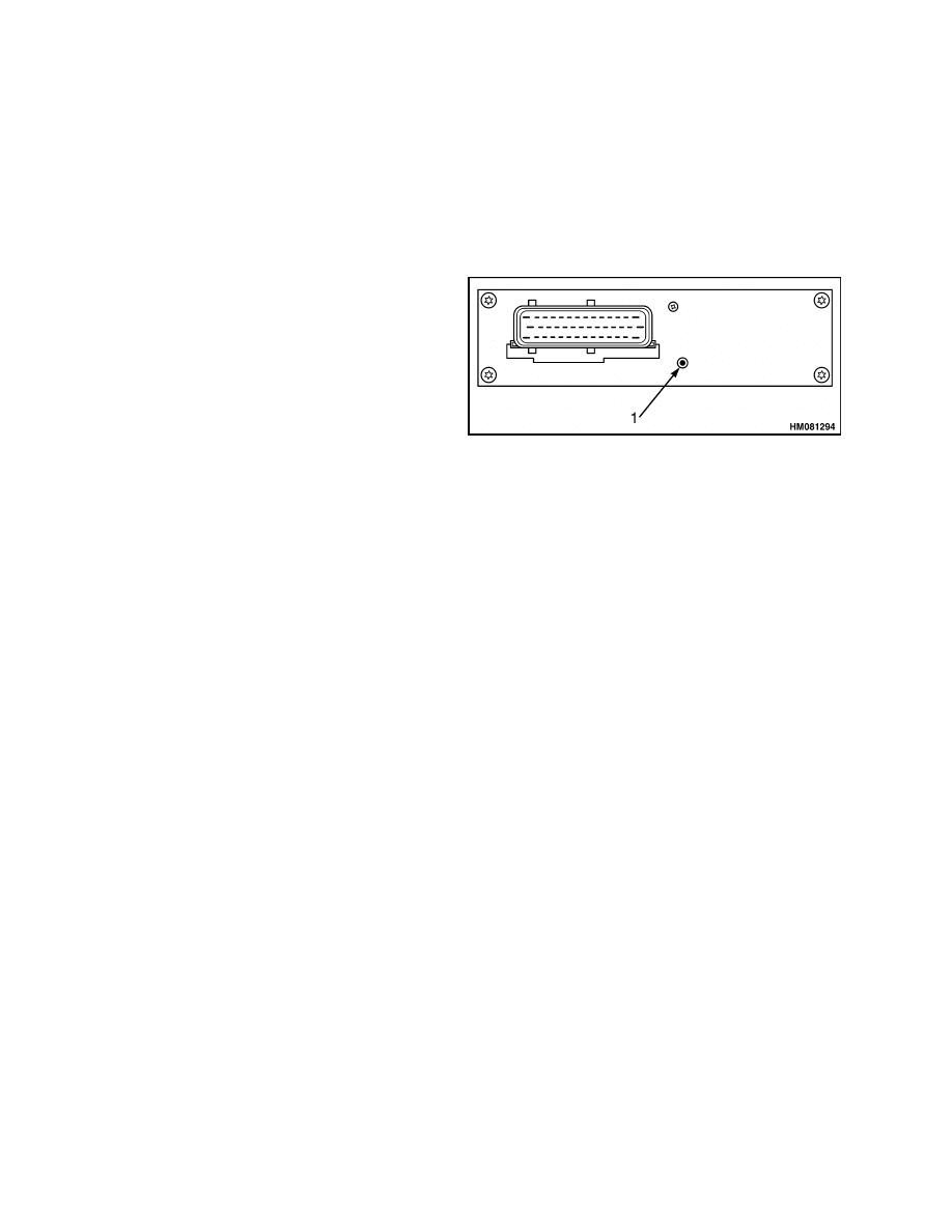
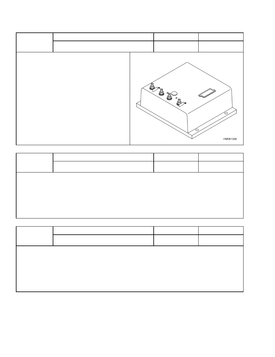
• The LED is located next to the wire harness con-
nector. See Figure 1.
• The LED blinking rate is usually twice a second,
when the battery is connected and the key is in the
OFF position.
• The LED blinking rate slows to once every two sec-
onds when the battery is connected and the key is
moved to the ON position.
• If the above conditions are not present, the master
controller may not be properly connected or may be
faulty.
• Due to the location of the master controller, a small
inspection mirror may be needed to view the LED.
1.
LED
Figure 1. AC Master Controller LED
AC Motor Controllers
NOTE: In Figure 2 through Figure 6 the terms Gen IV
and Gen V refer to Generation IV and Generation V
respectively. Controller and contactor panels labeled
Gen IV are used in early model lift trucks and con-
troller and contactor panels labeled Gen V are used
in later model lift trucks.
This section covers both the AC traction motor con-
trollers and AC pump motor controllers. Remove the
rear cover to view the motor controllers. See Fig-
ure 2, Figure 3, Figure 4, Figure 5, and Figure 6.
• The LED is located next to the label on the plastic
cover of the controller. See Figure 2 or Figure 3Fig-
ure 4 or Figure 5.
• The LED only turns on when the key is in the ON
position.
• The LED will show a steady continuous green color
if there is no fault condition detected.
• When a fault condition is detected that is not seri-
ous enough to shut down the truck, the LED blink-
ing rate is twice a second. A status code should ap-
pear on the dash display to reference the problem.
• When a fault condition is detected that has shut
down the truck, the LED blinking rate will be at
a very rapid rate (too fast to count). A status code
should appear on the dash display to reference the
problem.
• If the above conditions are not present, the AC mo-
tor controller may not be getting power from the
key switch or may be faulty.
8
2200 SRM 1056
Troubleshooting
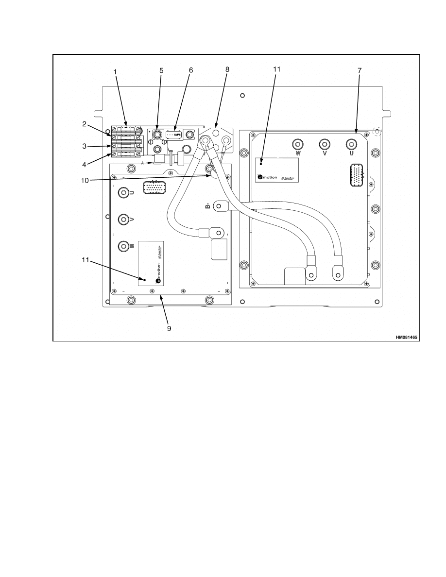
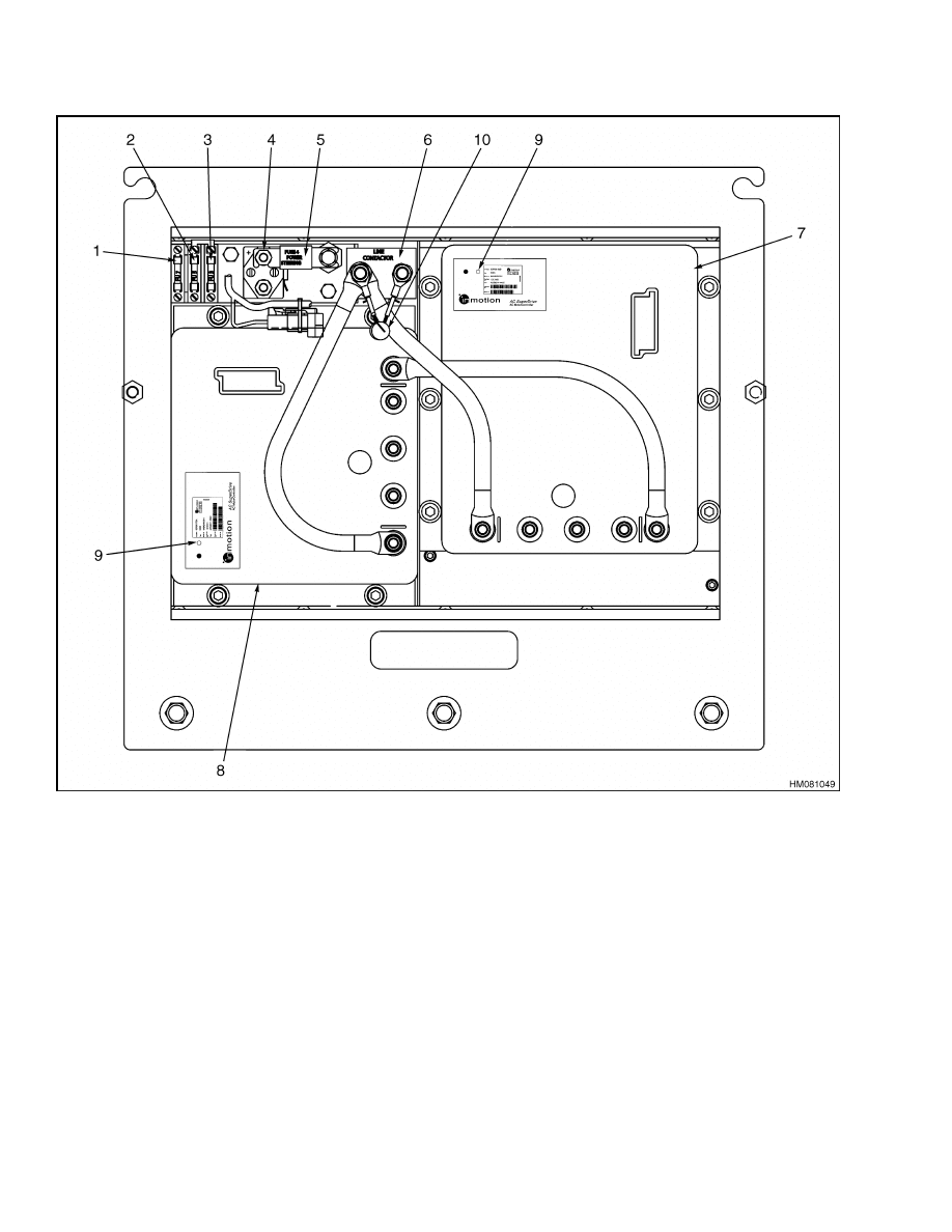
1.
FUSE 1 (15A) AUXILIARY TERMINAL STRIP
2.
FUSE 2 (15A) (SLOW BLOW) SEAT BRAKE
SOLENOID
3.
FUSE 3 (15A) LIGHTS
4.
FUSE 4 (5A) KEY SWITCH
5.
POWER STEERING CONTACTOR
6.
FUSE 5 (40 A) POWER STEERING
7.
AC TRACTION MOTOR CONTROLLER
8.
LINE CONTACTOR
9.
AC PUMP MOTOR CONTROLLER
10. POSITIVE TEMPERATURE COEFFICIENT
RESISTOR (PTC)
11. LED INDICATOR
Figure 2. AC Traction and AC Pump Motor Controllers (Gen V) (36v/48v or 72v/80v)
9

Troubleshooting
2200 SRM 1056
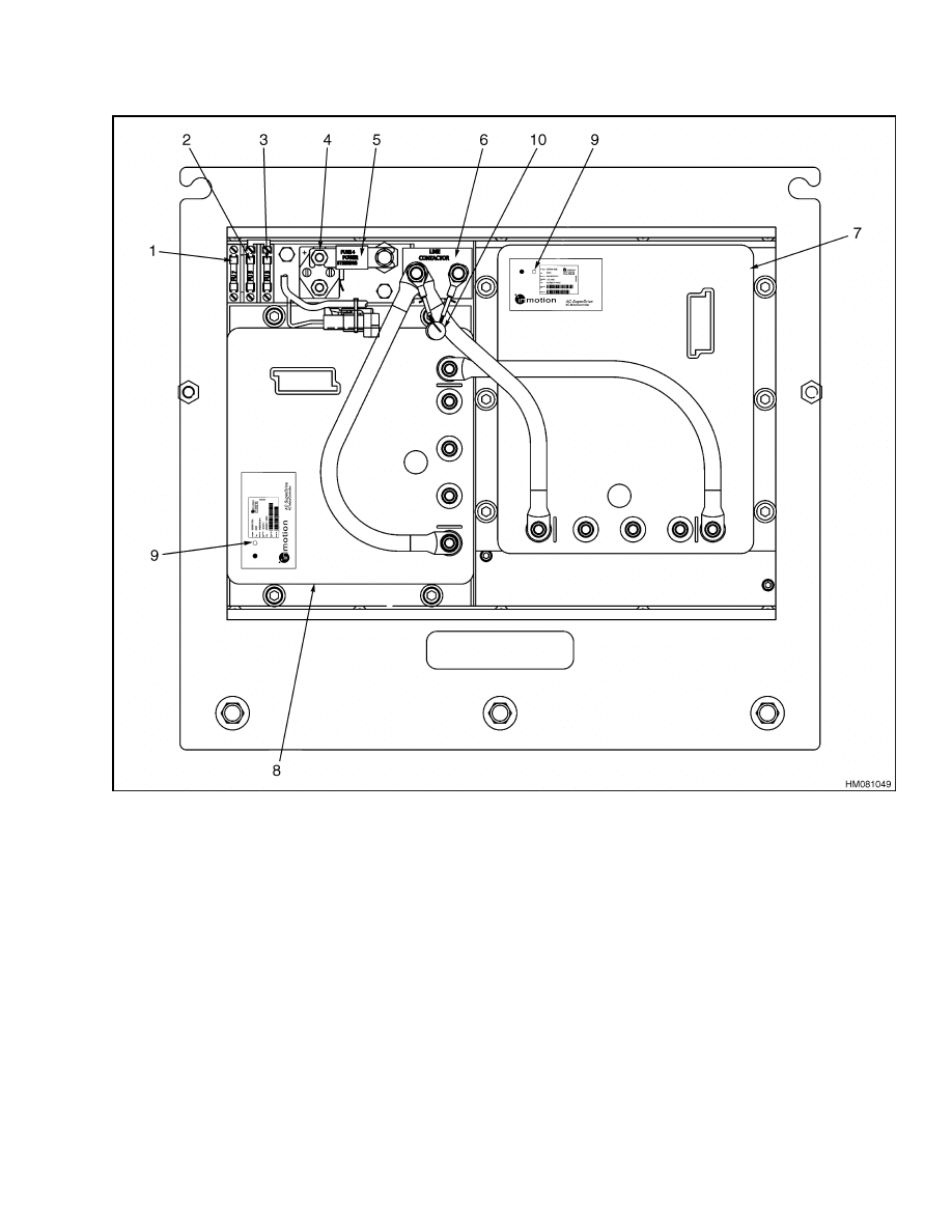
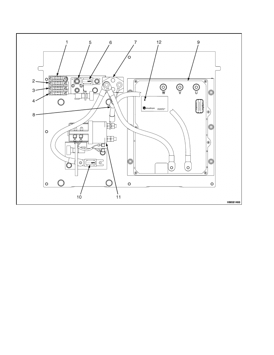
1.
FUSE 1 (15A) AUXILIARY TERMINAL STRIP
2.
FUSE 2 (15A) (SLOW BLOW) SEAT BRAKE
SOLENOID
3.
FUSE 3 (15A) LIGHTS
4.
FUSE 4 (5A) KEY SWITCH
5.
POWER STEERING CONTACTOR
6.
FUSE 5 (40A) POWER STEERING
7.
LINE CONTACTOR
8.
POSITIVE TEMPERATURE COEFFICIENT
RESISTOR (PTC)
9.
AC TRACTION MOTOR CONTROLLER
10. FUSE (325A) PUMP
11. CONTACTOR FOR DC PUMP MOTOR
12. LED INDICATOR
Figure 3. AC Traction Motor Controller and Contactor Control for DC Lift Pump Motor (Gen
V) (36v/48v or 72v/80v)
10
2200 SRM 1056
Troubleshooting
1.
FUSE 7 (15A) AUXILIARY TERMINAL STRIP
2.
FUSE 6 (15A) LIGHTS
3.
FUSE 3 (5A) KEY SWITCH
4.
POWER STEERING CONTACTOR
5.
FUSE 4 (40A) POWER STEERING
6.
LINE CONTACTOR
7.
AC TRACTION MOTOR CONTROLLER
8.
AC PUMP MOTOR CONTROLLER
9.
LED INDICATOR
10. POSITIVE TEMPERATURE COEFFICIENT
RESISTOR (PTC)
Figure 4. AC Traction and AC Pump Motor Controllers (72v/80v) (Gen IV)
11
Troubleshooting
2200 SRM 1056
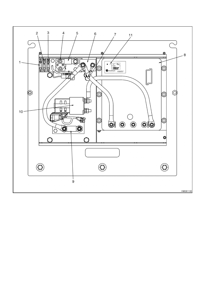
1.
FUSE 7 (15A) AUXILIARY TERMINAL STRIP
2.
FUSE 5 (15A) LIGHTS
3.
FUSE 3 (5A) KEY SWITCH
4.
POWER STEERING CONTACTOR
5.
FUSE 4 (40A) POWER STEERING
6.
LINE CONTACTOR
7.
POSITIVE TEMPERATURE COEFFICIENT
RESISTOR (PTC)
8.
AC TRACTION MOTOR CONTROLLER
9.
FUSE 2 (325A) PUMP
10. CONTACTOR FOR DC PUMP MOTOR
11. LED INDICATOR
Figure 5. AC Traction Motor Controller and Contactor Control for DC Lift Pump Motor (72v/80v)
(Gen IV)
12
2200 SRM 1056
Troubleshooting
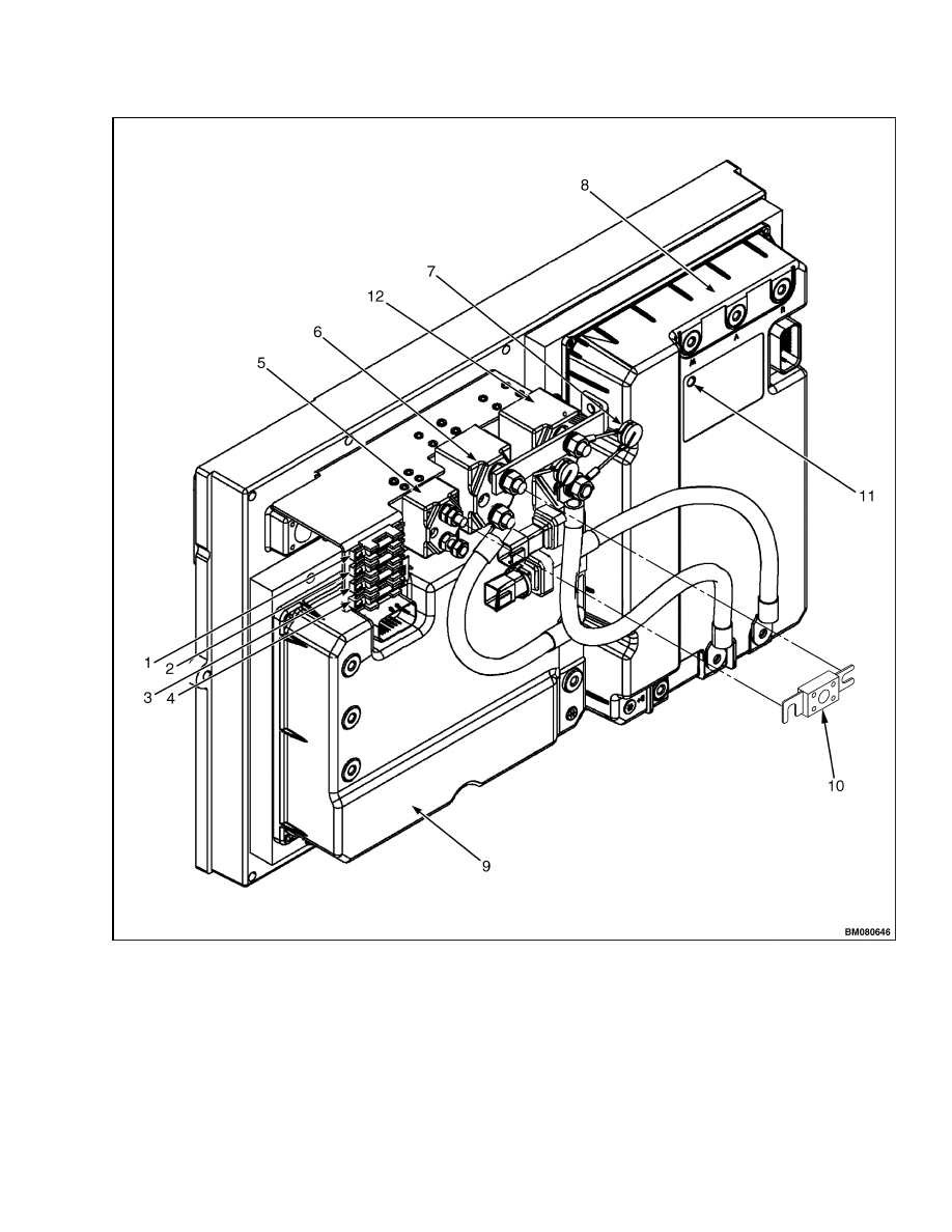
1.
FUSE 1 (15A) AUXILIARY
TERMINAL STRIP
2.
FUSE 2 (15A) (SLOW BLOW)
SEAT BRAKE SOLENOID
3.
FUSE 3 (15A) LIGHTS
4.
FUSE 4 (5A) KEY SWITCH
5.
POWER STEERING
CONTACTOR
6.
LINE TRACTION CONTACTOR
7.
POSITIVE TEMPERATURE
COEFFICIENT RESISTOR
(PTC)
8.
AC TRACTION MOTOR
CONTROLLER
9.
AC PUMP MOTOR
CONTROLLER
10. FUSE 5 (40A) POWER
STEERING
11. LED INDICATOR
12. LINE PUMP CONTACTOR
Figure 6. AC Traction and Pump Motor Controllers E3.50-5.50XL, E4.50XLS (E70-120Z, E100ZS)
(D098) Lift Truck Models
13
Troubleshooting
2200 SRM 1056
STATUS CODES
NOTE: Make sure the parameter values are correct
for your lift truck to ensure the trouble is not just
an incorrect setting. See Function Settings to set the
correct parameter values. If there is no status code
display and the lift truck does not operate correctly,
there can be a fault in the master controller.
The status codes are code numbers for malfunctions
or lift truck operations that are not correct and that
the motor controller can sense. The master controller
will indicate this code number on the LCD screen of
the display panel.
The master and motor controllers sense the following
types of malfunctions:
• Input voltages that are too high or too low
• Input voltages in the wrong sequence or
• Correct input voltages that occur at the wrong time
NOTE: A status code indication does not always mean
that there is a malfunction. A temporary operating
condition can cause a status code display.
These code numbers are only codes to help identify
a possible malfunction. A short description of the
different status codes is shown in Table 5.
The Status Code Charts in this section have a more
complete description of the status code, the circuit
that has generated the input for the status code, the
symptom, and the possible causes.
Table 5. List of Status Codes
Status Code
Description
Status Code
Description
BLANK
No input voltage to controller or
display panel.
52
Traction or pump motor speed sensor
error.
01
No seat switch input.
53
Traction controller does not respond
to master controller.
02
The forward switch is closed before
the key or seat switch closes.
54
Pump controller does not respond to
master controller.
03
The reverse switch is closed before
the key or seat switch closes.
55
Dash display cannot communicate
with master controller.
04
Park brake applied while the key
switch is in the ON position.
61
Current to cooling fans is too high
during operation.
05
Start switch fails to close.
62
Current to reverse relay is too high
during operation.
06
Accelerator depressed, no direction
selected.
63
Current to DC pump contactor coil is
too high during operation.
07
Acceleration voltage too high
when key is first moved to the ON
position.
64
Current to power steering contactor
coil is too high during operation.
08
Acceleration input voltage too low
when key is first moved to the ON
position.
65
Current to the line contactor coil is
too high during operation.
09
Both the forward and reverse
directional switches are closed at
the same time.
66
Short circuit sensed on power output
to traction motor.
11
The acceleration start switch
closed before the key and/or the
seat switch.
67
Short circuit sensed on power outage
to pump motor.
14
2200 SRM 1056
AC Motor Controllers Status Code Charts
Table 5. List of Status Codes (Continued)
Status Code
Description
Status Code
Description
15
Battery voltage is too low or master
controller is adjusted to the wrong
voltage.
68
Current to seat brake controller too
high during operation.
16
Battery voltage is too high or
master controller is adjusted to the
wrong battery voltage.
69
Current to the pump line contactor
coil is too high during operation.
41
Traction motor controller
overheated.
76
Capacitor voltage is too high.
42
Pump motor controller overheated.
90
Traction motor temperature too high.
43
Traction motor temperature sensor
out of range.
91
Pump motor temperature too high.
44
Pump motor temperature sensor
out of range.
95
Lift pump motor brushes are worn.
51
Capacitor volts are too low before
line contactor closes.
99
Maintenance Alert and Speed Limit.
AC Motor Controllers Status Code Charts
Description
Memory Recall
Circuit
Status Code
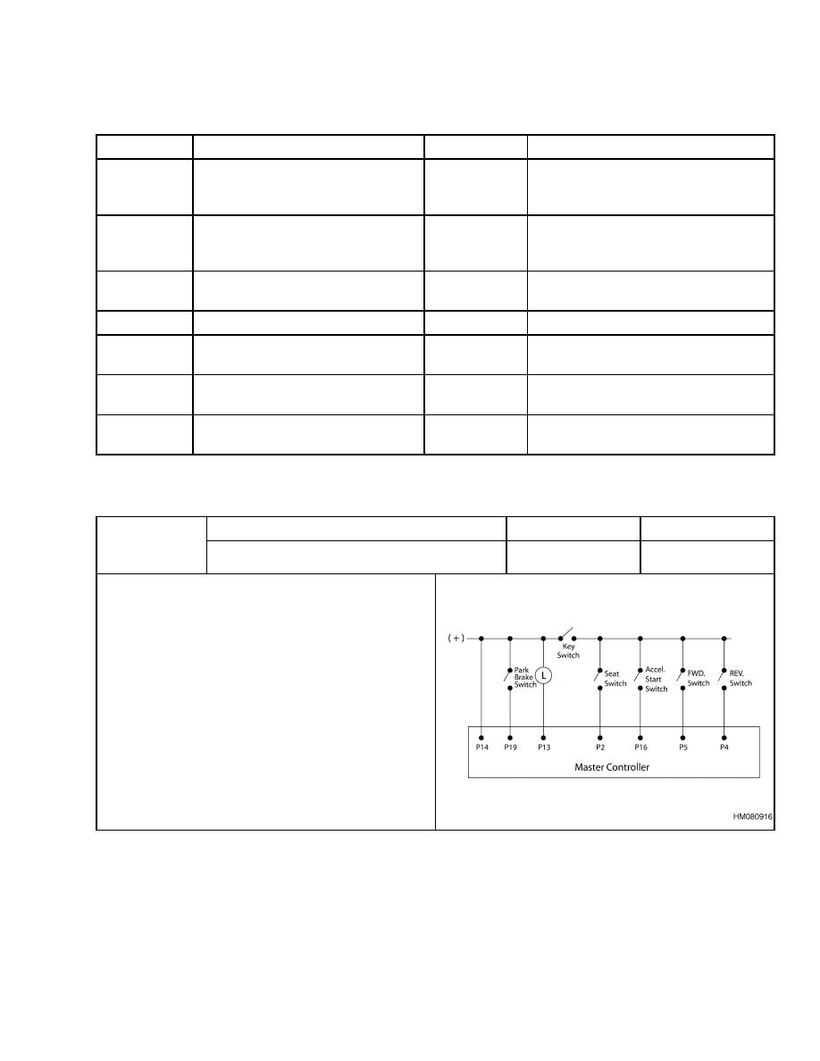
01
No seat switch input.
No
Traction
Symptom
Lift truck does not move.
Possible Causes and Test Procedures
• Seat switch malfunction.
Check to see that the seat switch operates prop-
erly.
Replace a failed switch.
• Check wiring to the seat switch and from the seat
switch to the master controller
15
AC Motor Controllers Status Code Charts
2200 SRM 1056
Description
Memory Recall
Circuit
Status Code
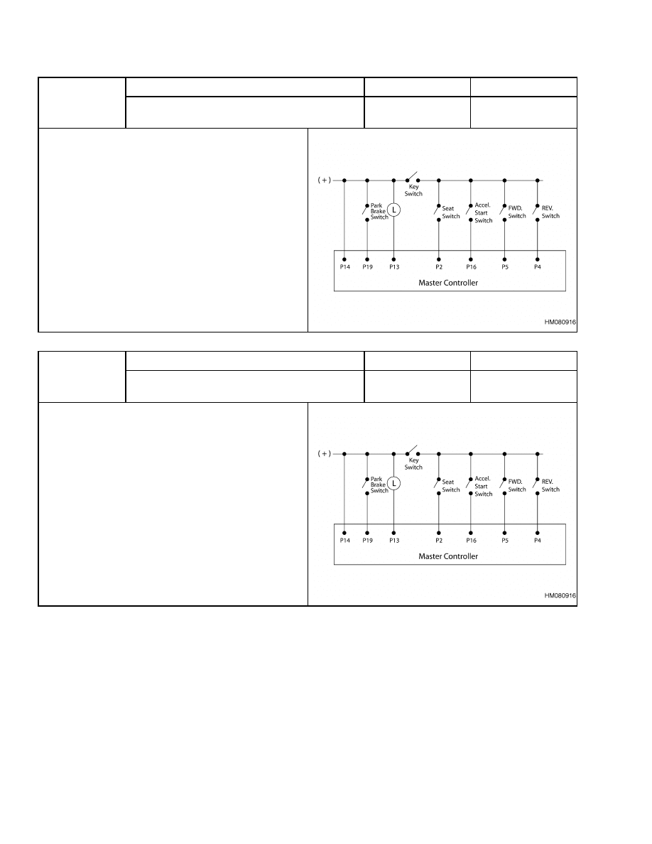
02
The forward switch is closed before the
key or seat switch closes.
No
Traction
Symptom
Lift truck does not operate.
Possible Causes and Test Procedures
• A directional switch is closed when the key switch is
turned to the ON position. This violates the Static
Return to Off (SRO) Startup Procedure, move the
directional lever to the neutral position, and then
select a direction.
• A directional switch is failed closed or out of adjust-
ment.
Description
Memory Recall
Circuit
Status Code
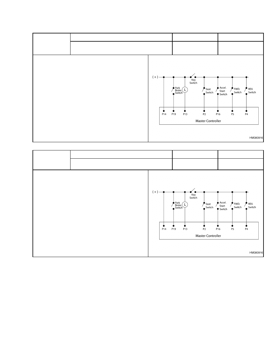
03
The reverse switch is closed before key
or seat switch closes.
No
Traction
Symptom
Lift truck does not operate.
Possible Causes and Test Procedures
• A directional switch is closed when the key switch is
turned to the ON position. This violates the Static
Return to Off (SRO) Startup Procedure, move the
directional lever to the neutral position, and then
select a direction.
• A directional switch is failed closed or out of adjust-
ment.
16
2200 SRM 1056
AC Motor Controllers Status Code Charts
Description
Memory Recall
Circuit
Status Code
04
Park brake applied while the key switch
is in the ON position.
No
Traction
Symptom
Lift truck does not move.
Possible Causes and Test Procedures
• Park brake is applied.
Truck will not operate with park brake applied.
Release the park break.
• Park brake switch is out of adjustment or is shorted.
Description
Memory Recall
Circuit
Status Code
05
Start switch fails to close.
No
Traction
Symptom
Lift truck does not move.
Possible Causes and Test Procedures
• Malfunction of start switch circuit.
Check for open circuit or loose connections in
wiring from key switch to start switch and from
P16 to start switch.
• Malfunction of start switch.
Check start switch for correct operation and out-
put.
17
AC Motor Controllers Status Code Charts
2200 SRM 1056
Description
Memory Recall
Circuit
Status Code
06
Accelerator depressed with no direc-
tion selected.
No
Traction
Symptom
Lift truck does not move.
Possible Causes and Test Procedures
• Accelerator pedal is depressed before closing a direc-
tion switch.
Status code will disappear when directional
switch is closed or when accelerator pedal is re-
leased.
• Malfunction of directional switch.
Check forward or reverse switch to make sure
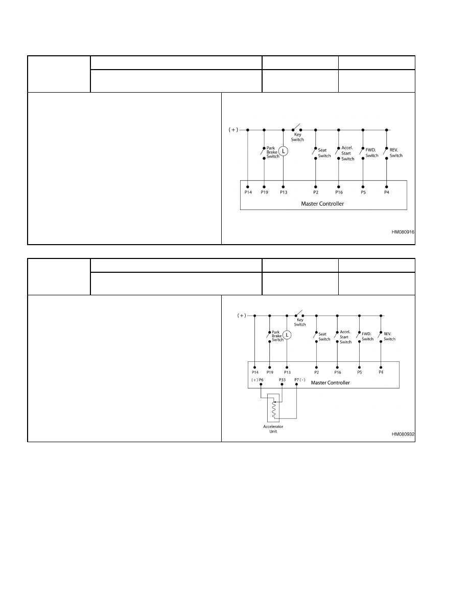
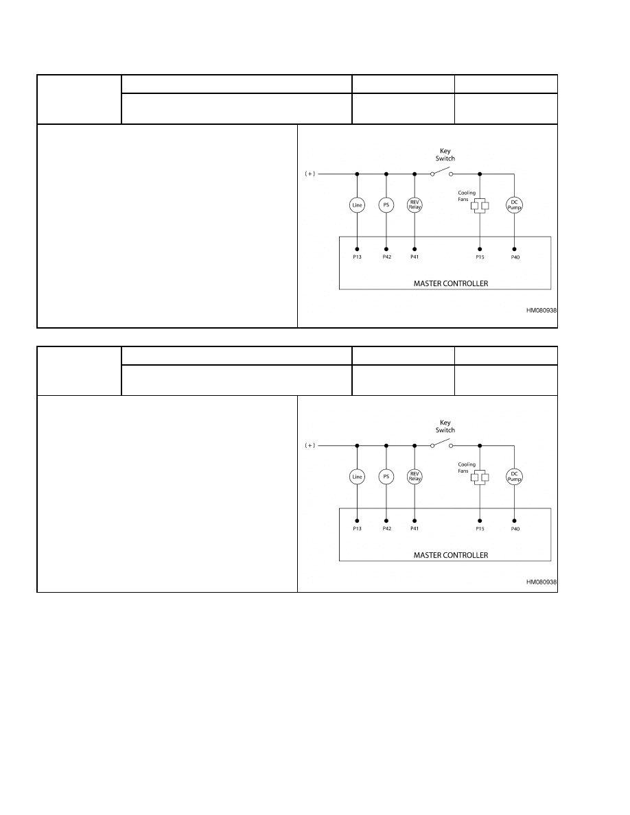
there is continuity when direction is selected.
• Open circuit between directional switch and battery
positive or between directional switch and P4 or P5.
Check all wires and connections shown in trou-
bleshooting diagram.
Description
Memory Recall
Circuit
Status Code
07
Accelerator input voltage too high when key
is first moved to ON position.
No
Traction
Symptom
Lift truck does not move.
Possible Causes and Test Procedures
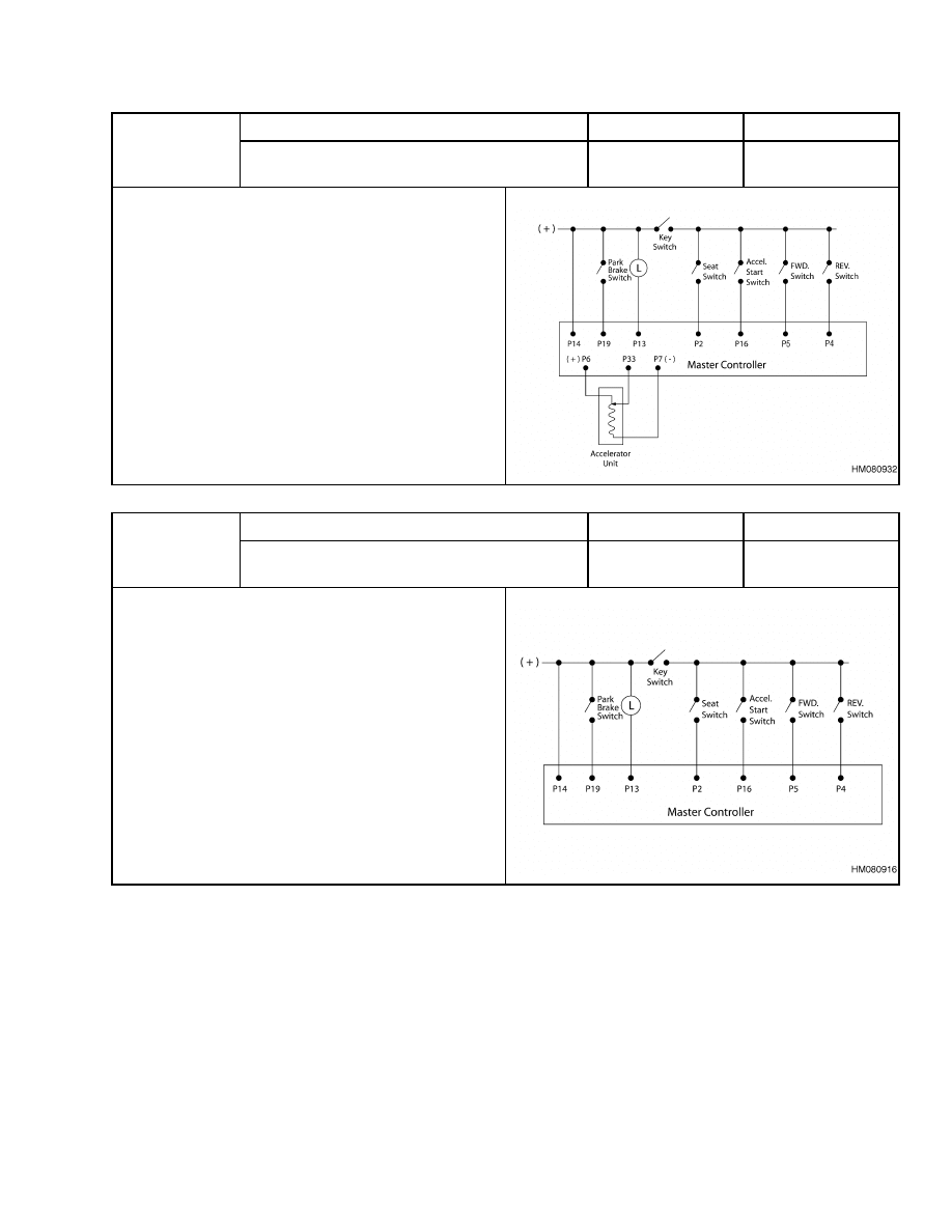
• Accelerator unit has a malfunction or is out of adjust-
ment. Maximum accelerator wiper voltage should be
11.00 volts with the pedal fully up.
• Open circuit between accelerator unit and P7.
18
2200 SRM 1056
AC Motor Controllers Status Code Charts
Description
Memory Recall
Circuit
Status Code
08
Accelerator input voltage too low when key
is first moved to the ON position.
No
Traction
Symptom
Lift truck does not move.
Possible Causes and Test Procedures
• Minimum accelerator wiper voltage should be 10.70
volts with the pedal fully up.
• Accelerator unit has malfunction or is out of adjust-
ment.
Description
Memory Recall
Circuit
Status Code
09
Both the forward and reverse directional
switches are closed at the same time.
No
Traction
Symptom
Lift truck does not move.
Possible Causes and Test Procedures
• Forward or reverse directional switch is failed closed
or out of adjustment (adjusted to be held closed).
Replace or adjust directional switches to make
sure they open when directional switch is re-
turned to neutral.
• Short circuit between battery positive and P4 and/or
P5.
Disconnect wires from P4 and P5 and check wire
for short circuit to positive side of directional
switch.
19
AC Motor Controllers Status Code Charts
2200 SRM 1056
Description
Memory Recall
Circuit
Status Code
11
The accelerator start switch closed before
the key and/or the seat switch.
No
Traction
Symptom
Lift truck does not move.
Possible Causes and Test Procedures
• The accelerator pedal was depressed when the key
was turned to the ON position. This violates the
Static Return to Off (SRO) Startup Procedure. To
correct this action, release the accelerator pedal and
resume normal operation.
• The accelerator pedal was depressed when the oper-
ator sat down. This violates the SRO Startup Proce-
dure. To correct this action, release the accelerator
pedal and resume normal operation.
• The accelerator start switch is out of adjustment or
has a short.
Description
Memory Recall
Circuit
Status Code
15
Battery voltage is too low or truck is adjusted
to the wrong battery voltage.
No
Traction
Symptom
Lift truck does not move.
Possible Causes and Test Procedures
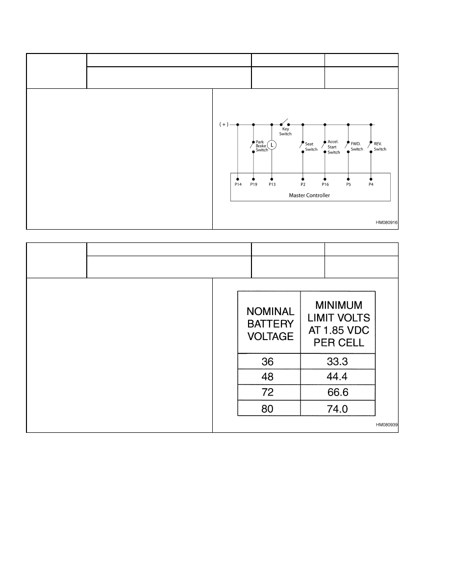
• Discharged battery.
Check battery for correct open circuit voltage.
Correct voltages are listed on right. Charge bat-
tery if required.
• Battery is damaged.
Check each battery cell for correct voltage (greater
than 1.85 volts each cell). Replace or repair bat-
tery.
• Incorrect master controller adjustment.
Check the battery volts setting in the master con-
troller for the correct battery volts.
• Check the battery volts on the main power cables at
the motor controllers.
20
2200 SRM 1056
AC Motor Controllers Status Code Charts
Description
Memory Recall
Circuit
Status Code
16
Battery voltage is too high or master controller
is adjusted to the wrong battery voltage.
No
Traction
Symptom
Lift truck does not move.
Possible Causes and Test Procedures
• Incorrect master controller adjustment.
Check the battery volts setting in the master con-
troller for the correct battery volts.
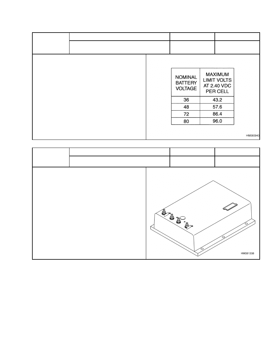
• Battery overcharged or incorrect battery used.
Check battery for correct open circuit voltage.
Correct voltages are listed on right. If voltage is
too high, check battery charger for correct output
voltage.
Description
Memory Recall
Circuit
Status Code
41
Traction motor controller overheated.
Yes
Traction
Symptom
Truck acceleration is reduced or truck may
stop completely.
Possible Causes and Test Procedures
• Excessive pushing or stalling of traction motor.
• Check operation of cooling fans.
See Fan Test.
• Check for proper application of thermal grease be-
tween motor controller and heat sink.
21
AC Motor Controllers Status Code Charts
2200 SRM 1056
Description
Memory Recall
Circuit
Status Code
42
Pump motor controller overheated.
Yes
Traction
Symptom
Truck acceleration and travel speed is reduced
and pump motor may stop completely.
Possible Causes and Test Procedures
• Excessive operation or stalling of the pump motor.
• Check operation of the cooling fans.
See Fan Test.
• Check for proper application of thermal grease be-
tween motor controller and heat sink.
Description
Memory Recall
Circuit
Status Code
43
Traction motor temperature sensor out of range.
No
Traction
Symptom
Status code is displayed for 10 seconds after startup. Truck still operates, but traction
motor overtemperature protection is inoperative.
Possible Causes and Test Procedures
• Wiring from motor temperature sensor to the motor controller is open or has shorted.
• Motor temperature sensor is faulty.
Replace the motor, or operate without the temperature sensor.
Description
Memory Recall
Circuit
Status Code
44
Pump motor temperature sensor out of range.
No
Pump
Symptom
Status code is displayed for 10 seconds after startup. Truck still operates, but pump
motor overtemperature protection is inoperative.
Possible Causes and Test Procedures
• Wiring from motor temperature sensor to the motor controller is open or has shorted.
• Motor temperature sensor is faulty.
Replace the motor, or operate without the temperature sensor.
22
2200 SRM 1056
AC Motor Controllers Status Code Charts
Description
Memory Recall
Circuit
Status Code
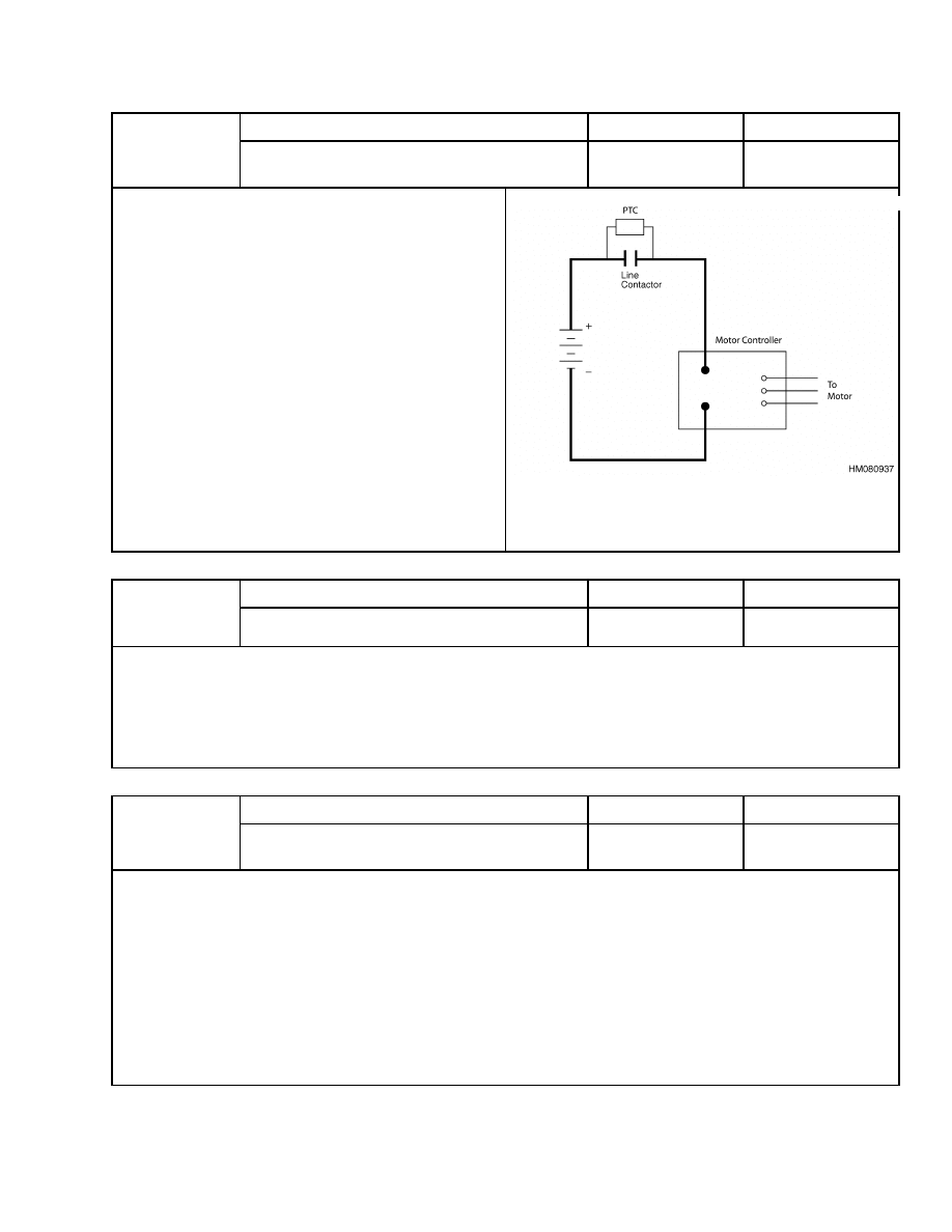
51
Capacitor volts are too low before line
contactor closes.
No
Traction
Symptom
Lift truck does not move and line contac-
tor does not close.
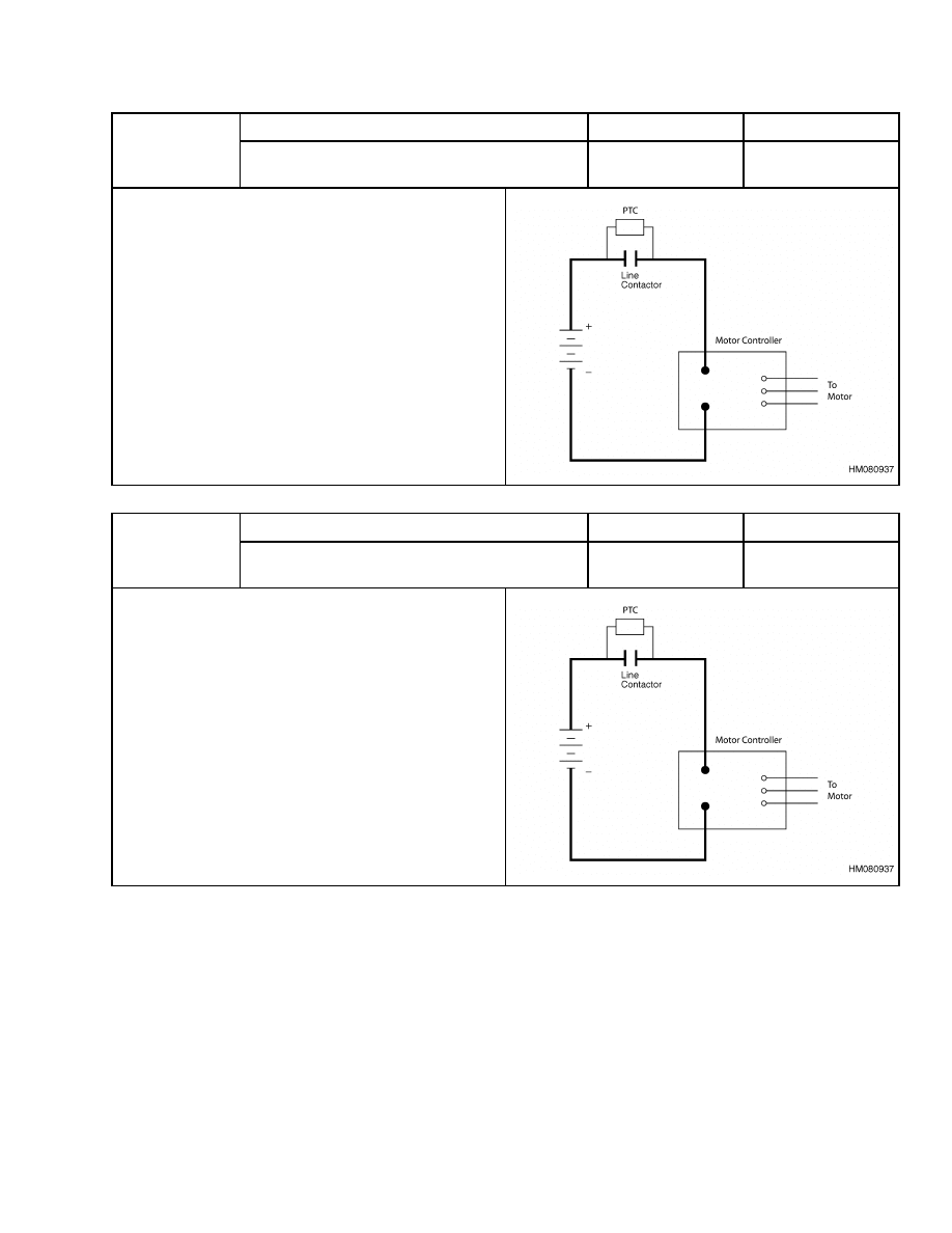
Possible Causes and Test Procedures
• A Positive Temperature Coefficient (PTC) is discon-
nected or malfunctioning, preventing the capacitors
to charge when the battery is plugged in.
• An accessory or component other than the motor con-
trollers is connected to load side of line contactor.
This will cause the PTC to get hot and not charge
the capacitors.
• Repeated charging/discharging the capacitors dur-
ing troubleshooting may cause a Status Code 51. If
the PTC is hot, allow it to cool.
• Status code will occur if the line contactor does not
close properly and truck operation is attempted.
• Status code will occur if battery voltage drops below
50% nominal voltage.
Description
Memory Recall
Circuit
Status Code
52
Traction or pump motor speed sensor error.
No
Traction
Symptom
Traction or pump motor operates very slowly and jerky.
Possible Causes and Test Procedures
• Disconnected or broken sensor wires between motor and motor controller.
• Malfunction of motor encoder bearing.
Description
Memory Recall
Circuit
Status Code
53
Traction controller does not respond to
master controller.
No
Traction
Symptom
Lift truck does not move.
Possible Causes and Test Procedures
• Malfunction of motor controller.
Check key switch input to motor controller.
See Controller Status Light Emitting Diodes (LEDs).
• CANbus communication between motor controller and master controller is not working.
Check for loose or broken wires.
• Open connection between motor controller pin 13 (ground) and pin 12 and/or pin 20. See the Electrical
Diagrams manual for your lift truck model. Pins 12 and 20 are truck I.D. pins.
23
AC Motor Controllers Status Code Charts
2200 SRM 1056
Description
Memory Recall
Circuit
Status Code
54
Pump controller does not respond to
master controller.
No
Traction
Symptom
Hydraulic pump motor does not operate.
Possible Causes and Test Procedures
• Malfunction of motor controller.
Check key switch input to motor controller.
See Controller Status Light Emitting Diodes (LEDs).
• CANbus communication between motor controller and master controller is not working
Check for loose or broken wires.
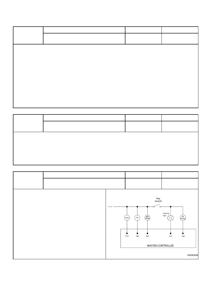
• This status code may appear on trucks with contactor controlled DC pump motors. The master controller
senses the presence of a contactor by a voltage on pin 40. If there is no voltage on pin 40, the master con-
troller assumes an AC pump motor controller is present, but not able to communicate.
Check for voltage at the pump contactor coil.
Check wiring from pump contactor coil to master controller, pin 40.
Description
Memory Recall
Circuit
Status Code
55
Dash display cannot communicate with
master controller.
Yes
Traction
Symptom
Varies due to problem.
Possible Causes and Test Procedures
• If truck operates and code is displayed on dash, the CANbus communication is not working.
Check for loose or broken wires.
• If truck does not operate and code is displayed on dash, fault may be in master controller.
Description
Memory Recall
Circuit
Status Code
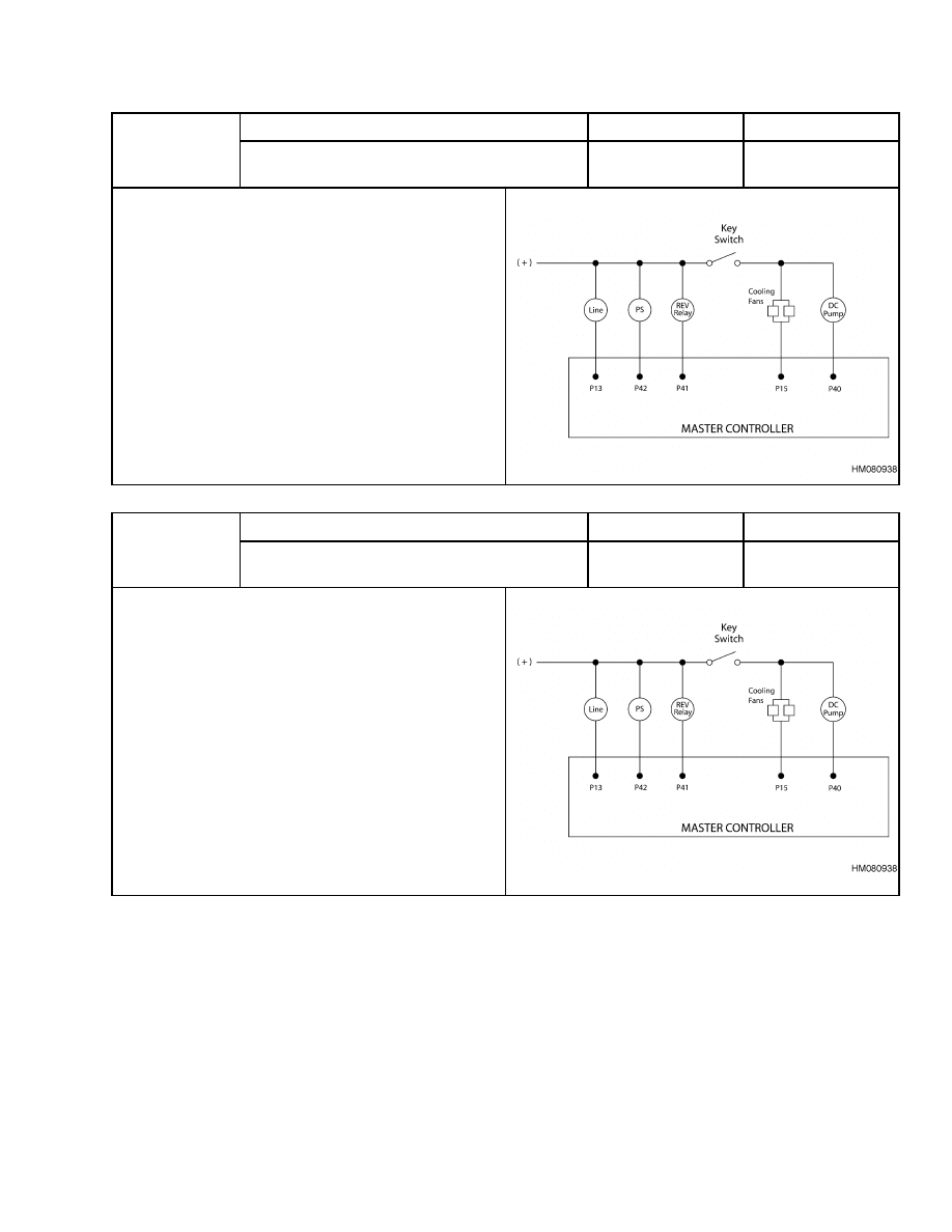
61
Current to cooling fans is too high
during operation.
No
Traction
Symptom
Lift truck does not move. If fault occurred during
truck operation, status code will not display until the
key switch is cycled to OFF and then to ON again.
Possible Causes and Test Procedures
• A fan or wiring to fan may have a short.
• Trucks using a fan power supply may have a short in
the power supply.
• If the status code is displayed while fans or power
supply are disconnected, fault is probably in the mas-
ter controller.
24
2200 SRM 1056
AC Motor Controllers Status Code Charts
Description
Memory Recall
Circuit
Status Code
62
Current to reverse relay is too high
during operation.
No
Traction
Symptom
Lift truck does not move. If fault occurred during
truck operation, status code will not display until the
key switch is cycled to OFF and then to ON again.
Possible Causes and Test Procedures
• Reverse relay coil or wiring coil may have a short.
Check the coil resistance with the wires discon-
nected. The approximate resistance is 160 ohms.
• If status code is displayed while relay coil wires are
disconnected, the fault is probably in master con-
troller.
Description
Memory Recall
Circuit
Status Code
63
Current to DC pump contactor coil is too
high during operation.
No
Traction
Symptom
Lift truck does not move. If fault occurred during
truck operation, status code will not display until the
key switch is cycled to OFF and then to ON again.
Possible Causes and Test Procedures
• DC pump contactor coil or wiring to coil may have a
short.
Check the coil resistance with wires disconnected.
Approximate coil resistance, at room tempera-
ture, should be:
36/48 volt trucks 31 ohms
72/80 volt trucks 70 ohms
• If status code is displayed while contactor coil wires
are disconnected, the fault is probably in master con-
troller.
25
AC Motor Controllers Status Code Charts
2200 SRM 1056
Description
Memory Recall
Circuit
Status Code
64
Current to power steering contactor coil
is too high during operation.
No
Traction
Symptom
Lift truck does not move. If fault occurred during
truck operation, status code will not display until the
key switch is cycled to OFF and then to ON again.
Possible Causes and Test Procedures
• Power steering contactor coil or wiring to coil may
have a short.
Check the coil resistance with wires disconnected.
Approximate coil resistance, at room tempera-
ture, should be:
36/48 volt trucks 174 ohms
72/80 volt trucks 600 ohms
• If status code is displayed while contactor coil wires
are disconnected, the fault is probably in master con-
troller.
Description
Memory Recall
Circuit
Status Code
65
Current to the line contactor coil is too
high during operation.
No
Traction
Symptom
Lift truck does not move. If fault occurred during
truck operation, status code will not display until the
key switch is cycled to OFF and then to ON again.
Possible Causes and Test Procedures
• Line contactor coil or wire to coil has a short.
Check the coil resistance with wires disconnected.
Approximate coil resistance, at room tempera-
ture, should be:
36/48 volt trucks 31 ohms
72/80 volt trucks 85 ohms
• If status code is displayed while contactor coil wires
are disconnected, the fault is probably in master con-
troller.
26
2200 SRM 1056
AC Motor Controllers Status Code Charts
Description
Memory Recall
Circuit
Status Code
66
Short circuit sensed on power output
to traction motor.
No
Traction
Symptom
Lift truck does not move.
Possible Causes and Test Procedures
• Short circuit in motor or heavy power wires going to
motor.
• If status code is displayed with motor power wires
disconnected, the short circuit is internal.
Replace motor controller.
Description
Memory Recall
Circuit
Status Code
67
Short circuit sensed on power output
to pump motor.
No
Traction
Symptom
Hydraulic pump motor does not operate.
Possible Causes and Test Procedures
• Short circuit in motor or heavy power wires going to
motor
• If status code is displayed with motor power wires
disconnected, short circuit is internal.
Replace motor controller.
27
AC Motor Controllers Status Code Charts
2200 SRM 1056
Description
Status Code
68
Current to seat brake controller too
high during operation.
Memory Recall
No
Symptom
Lift truck does not move, and seat brake
does not release.
If fault occurs during truck operation, status code
does not display until the key switch is turned to the
OFF position and then turned to the ON position.
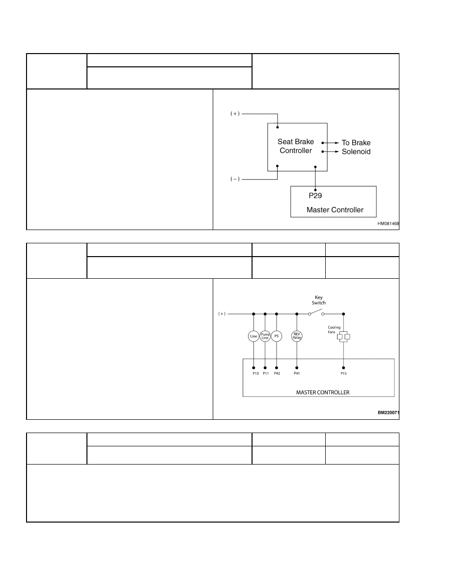
Possible Causes and Test Procedures
• Seat brake controller or wire to controller has a short
• If status code is displayed with the wires discon-
nected, the fault is probably in the master controller
Description
Memory Recall
Circuit
Status Code
69
Current to the pump line contactor coil is
too high during operation.
No
Traction
Symptom
Lift truck does not move. If fault occurred during
truck operation, status code will not display until the
key switch is cycled to OFF and then to ON again.
Possible Causes and Test Procedures
• Pump line contactor coil or wire to coil has a short.
Check the coil resistance with wires disconnected.
Approximate coil resistance, at room tempera-
ture, should be:
36/48 volt trucks 31 ohms
72/80 volt trucks 85 ohms
• If status code is displayed while contactor coil wires
are disconnected, the fault is probably in master con-
troller.
Description
Memory Recall
Circuit
Status Code
76
Capacitor voltage too high.
No
Traction
Symptom
Lift truck does not work.
Possible Causes and Test Procedures
• Regen setting too high.
Combination of a fully charged battery and a high regen setting may cause status code.
28
2200 SRM 1056
AC Motor Controllers Status Code Charts
Description
Memory Recall
Circuit
Status Code
90
Traction motor temperature too high.
Yes
Traction
Symptom
Truck acceleration is reduced, or truck may stop completely.
Possible Causes and Test Procedures
• Excessive pushing or stalling of traction motor.
• Operation may continue at slower duty cycle.
Allow traction motor to cool to regain full performance.
• Comparing the motor temperature through the display panel with a known motor temperature, such as
room temperature, can check the motor temperature sensor.
• A shorted or open temperature sensor will generate a status code 43.
Description
Memory Recall
Circuit
Status Code
91
Pump motor temperature is too high.
Yes
Pump
Symptom
Truck acceleration and travel speed reduced. Pump motor may stop completely.
Possible Causes and Test Procedures
• Excessive operation or stalling of pump motor.
• Operation may continue at slower duty cycle.
Allow pump motor to cool off to regain full performance.
• Comparing the motor temperature through the display panel with a known motor temperature, such as
room temperature, can check the motor temperature sensor.
• A shorted or open temperature sensor will generate a status code 43.
Description
Memory Recall
Circuit
Status Code
95
DC lift pump motor brushes are worn.
Yes
Pump
Symptom
Status code warning only.
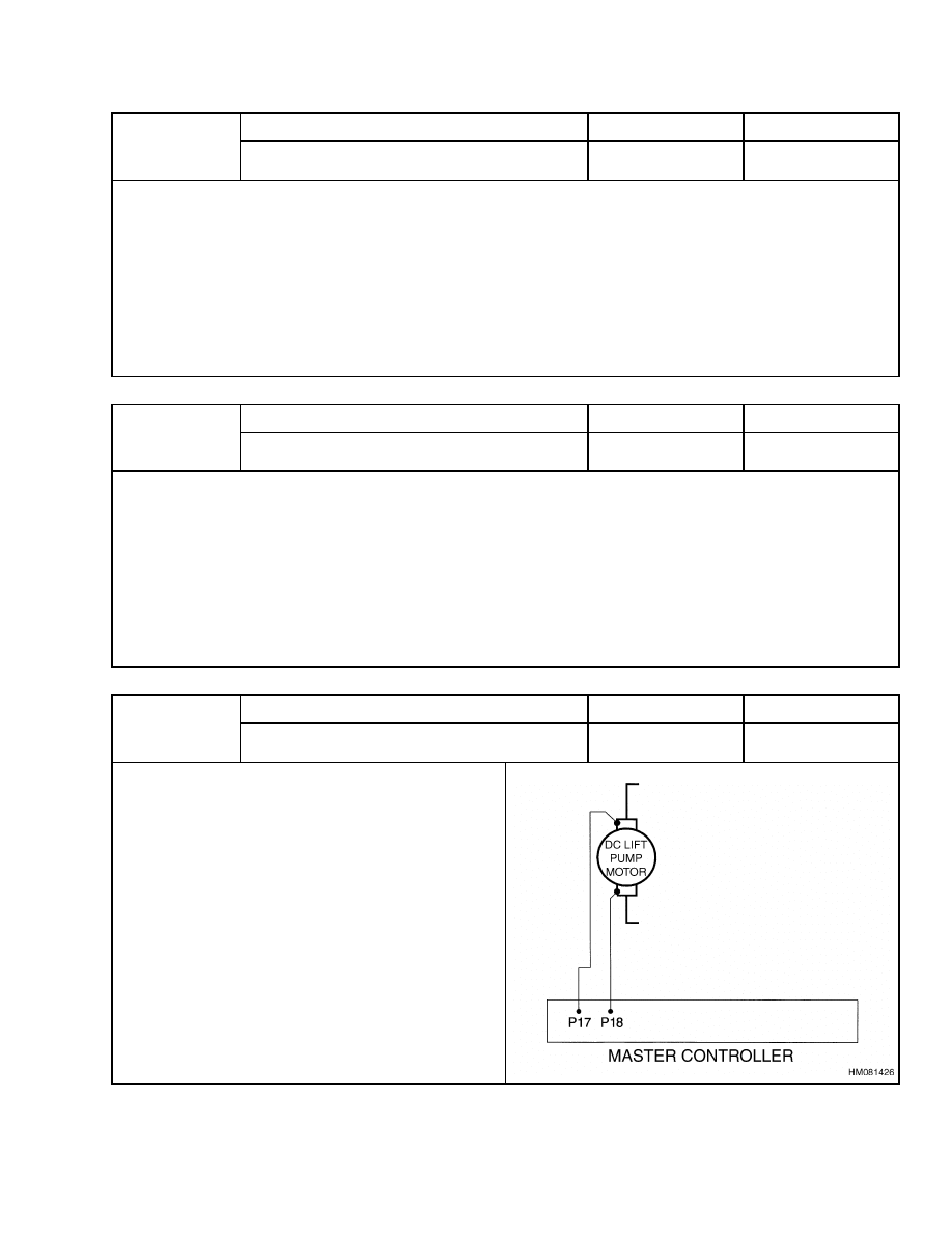
Possible Causes and Test Procedures
• Pump motor brushes are worn too short.
• Motor brush wear sensor wires to motor controller
may have a short to battery positive.
29

AC Transistor Motor Controller Replacement
2200 SRM 1056
Description
Memory Recall
Circuit
Status Code
99
Maintenance Alert and Speed Limit.
No
Traction
Symptom
Status code is displayed and, after 20 hours, truck speed is reduced to 50% of normal top speed.
Possible Causes and Test Procedures
• Maintenance reminder indicating it is time to service truck. It was set by a technician through the dash
display or with a PC.
• The technician must perform desired maintenance and reset reminder to next hourmeter reading that main-
tenance should occur.
AC Transistor Motor Controller Replacement
GENERAL
NOTE: In Figure 7 through Figure 11, the terms Gen
IV and Gen V refer to Generation IV and Genera-
tion V respectively. Controller and contactor panels
labeled Gen IV are used in early model lift trucks
and controller and contactor panels labeled Gen V
are used in later model lift trucks.
The assembly of the AC Traction Motor Controller
with AC Pump Motor controller is shown in Figure 7,
Figure 8, and Figure 9. The assembly of the AC Trac-
tion Motor controller with DC Lift Pump Motor is
shown in Figure 10 and Figure 11. There are NO
internal parts of these motor controllers that can be
repaired. Each of these motor controllers must be re-
placed if an internal malfunction occurs.
30

2200 SRM 1056
AC Transistor Motor Controller Replacement
1.
FUSE 1 (15A)
2.
FUSE 2 (15A) (SLOW)
3.
FUSE 3 (15A)
4.
FUSE 4 (5A)
5.
POWER STEERING CONTACTOR
6.
FUSE 4 (POWER STEERING) (40A)
7.
AC TRACTION MOTOR CONTROLLER
8.
LINE CONTACTOR
9.
AC PUMP MOTOR CONTROLLER
10. POSITIVE TEMPERATURE COEFFICIENT
RESISTOR (PTC)
11. LED INDICATOR
Figure 7. AC Traction and AC Pump Motor Controllers (Gen V) (36v/48v or 72v/80v)
31
AC Transistor Motor Controller Replacement
2200 SRM 1056
1.
FUSE 7 (15A)
2.
FUSE 5 (15A)
3.
FUSE 3 (5A)
4.
POWER STEERING CONTACTOR
5.
FUSE 4 (POWER STEERING) (40A)
6.
LINE CONTACTOR
7.
AC TRACTION MOTOR CONTROLLER
8.
AC PUMP MOTOR CONTROLLER
9.
LED INDICATOR
10. POSITIVE TEMPERATURE COEFFICIENT
RESISTOR (PTC)
Figure 8. AC Traction and AC Pump Motor Controllers (72v/80v) (Gen IV)
32

2200 SRM 1056
AC Transistor Motor Controller Replacement
1.
FUSE 1 (15A)
2.
FUSE 2 (15A) (SLOW)
3.
FUSE 3 (15A)
4.
FUSE 4 (5A)
5.
POWER STEERING
CONTACTOR
6.
LINE TRACTION CONTACTOR
7.
POSITIVE TEMPERATURE
COEFFICIENT RESISTOR
(PTC)
8.
AC TRACTION MOTOR
CONTROLLER
9.
AC PUMP MOTOR
CONTROLLER
10. POWER STEERING FUSE
(40A)
11. LED INDICATOR
12. LINE PUMP CONTACTOR
Figure 9. AC Traction and Pump Motor Controllers E3.50-5.50XL, E4.50XLS (E70-120Z, E100ZS)
(D098) Lift Truck Models
33
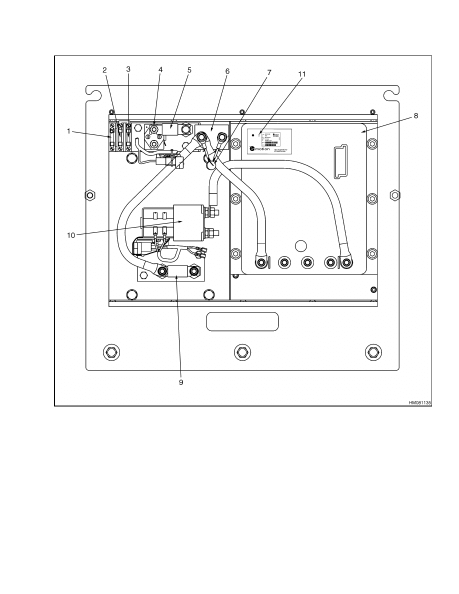
AC Transistor Motor Controller Replacement
2200 SRM 1056
1.
FUSE 1 (15A)
2.
FUSE 2 (15A) (SLOW)
3.
FUSE 3 (15A)
4.
FUSE 4 (5A)
5.
POWER STEERING CONTACTOR
6.
FUSE 4 (POWER STEERING) (40A)
7.
LINE CONTACTOR
8.
POSITIVE TEMPERATURE COEFFICIENT
RESISTOR (PTC)
9.
AC TRACTION MOTOR CONTROLLER
10. FUSE (PUMP) (325A)
11. CONTACTOR FOR DC PUMP MOTOR
12. LED INDICATOR
Figure 10. AC Traction Motor Controller and Contactor Control for DC Lift Pump Motor (Gen
V) (36v/48v or 72v/80v)
34
2200 SRM 1056
AC Transistor Motor Controller Replacement
1.
FUSE 7 (15A)
2.
FUSE 5 (15A)
3.
FUSE 3 (5A)
4.
POWER STEERING CONTACTOR
5.
FUSE 4 (POWER STEERING) (40A)
6.
LINE CONTACTOR
7.
POSITIVE TEMPERATURE COEFFICIENT
RESISTOR (PTC)
8.
AC TRACTION MOTOR CONTROLLER
9.
FUSE 2 (PUMP) (325A)
10. CONTACTOR FOR DC PUMP MOTOR
11. LED INDICATOR
Figure 11. AC Traction Motor Controller and Contactor Control for DC Lift Pump Motor (72v/80v)
(Gen IV)
35

AC Transistor Motor Controller Replacement
2200 SRM 1056
GENERAL MAINTENANCE
INSTRUCTIONS
The motor controllers, like other electronic devices,
have temperature limits. These devices can be dam-
aged if they get too hot. Normal maintenance will
help prevent high-temperature conditions. Always
make sure motor controllers are installed using heat
sink compound and that all heat sink surfaces are
clean. Do not block cooling airflow.
Special Precautions
WARNING
To avoid injury and prevent electrical shock,
perform
the
following
steps
before
trou-
bleshooting, adjustments, or repair:
• Turn the key to the OFF position and discon-
nect the battery connector.
• Discharge the capacitors in the controllers
using the horn.
Move the key to the OFF
position, disconnect the battery connector,
and hold the horn button until the horn stops
making a sound.
CAUTION
To help prevent controller damage:
• ALWAYS disconnect the battery when servic-
ing the controllers.
• ALWAYS discharge the capacitors using the
horn before performing any service.
• NEVER make a short circuit at any motor
controller terminal to battery (+), battery ( ),
or the frame.
• Remove the motor controllers before per-
forming any authorized welding procedures.
CAUTION
Never add any electrical component to the lift
truck without approval from your dealer for
your lift truck. Other electrical components
can prevent operation and/or damage the mo-
tor controller.
NEVER USE STEAM TO CLEAN ELECTRONIC
COMPONENTS.
In dusty areas, blow low pressure air over the con-
troller to remove dust. In oily or greasy areas, a
mild solution of detergent or denatured alcohol can
be used to wash off the controller; and then, low pres-
sure air should be used to completely dry the con-
troller.
For the controller to be most effective, it must be
mounted against the finned aluminum heat sink.
This additional heat sink will give improved lift
truck performance by keeping the controller package
cooler. During installation of the controller, apply
a sufficient layer of silicone (heat transfer) grease
Hyster P/N 1198757 between the controller and the
heat sink to not allow air gaps between the two.
Controller wire plugs and other exposed transistor
controller parts should be kept free of dirt and paint
that might change the effective resistance between
points.
CAUTION
Do NOT operate the traction system at high
speed or rapidly change direction of operation
with the wheels raised. Motor controller dam-
age can occur.
Do not subject the controller to any high voltage
(hipot or megger) testing.
Use a lead acid battery with the voltage and ampere
hour rating specified for the lift truck. Follow normal
battery maintenance procedures, recharging at 80
percent discharge, with monthly equalizing charges.
Parts of these assemblies not covered in this manual
cannot be repaired and must be replaced if they mal-
function. The contactors do have parts that can be
replaced.
36
2200 SRM 1056
AC Transistor Motor Controller Replacement
WARNING
Some checks in this section must be done with
the battery connected and power applied to
the controller.
When making these checks,
make sure the drive wheels are raised from
the floor. See Procedures given in the Periodic
Maintenance Manual or the Operating Manual
for your lift truck.
Make sure you disconnect the battery and
separate the connector before you remove any
power cables from the power terminals of the
motor controller.
The capacitor stores elec-
trical energy and can cause injury if a person
discharges a capacitor through parts of the
body. AFTER the battery is disconnected and
the key in the OFF position, make sure you
also discharge the capacitors. Discharge the
capacitors by pushing and holding the horn
button until the horn stops making a sound.
The capacitors discharge through the horn.
NOTE: The bolts and screws connected to the elec-
tronic components are normally metric sizes.
Make sure that you use the correct fastener for the
part that has been disassembled or removed.
FUSES
The fuses are found on the contactor panels. See Fig-
ure 7, Figure 8, Figure 9, Figure 10, and Figure 11.
The condition of the fuses can normally be checked
by looking at them. Some fuses do not change in ap-
pearance and must be checked with an ohmmeter.
FAN TEST
To determine if the fans are operating correctly, go
to the Access to Service Functions section of this
SRM. Using the procedures in that section, go to
Diagnostics Menu and select No Run Diagnostics.
From there, go to Fan On, which is the last menu
item. As soon as Fan On is selected, the fans should
start running.
On 36/48 volt trucks, the fans operate at battery volt-
age. If battery voltage is present at the fan terminal
strip and the fan(s) doesn’t run, replace the fan(s).
If battery voltage is not present at the fan terminal
strip, look for problems in the positive circuit from
the key switch or the negative circuit to pin 15 on
the master controller.
On 72/80 volt trucks, the fans operate with a fan
power supply. If the power supply voltage (48 volts) is
present and the fan(s) doesn’t run, then replace the
fan(s). If there is battery voltage to the fan power
supply and there is no output voltage, then replace
the fan power supply. If battery voltage is not present
at the power supply, look for problems in the positive
circuit from the key switch or the negative circuit to
pin 15 on the master controller.
CONTACTORS
There can be three contactors on these lift trucks.
All lift trucks have a power steering contactor and
a line contactor. See Figure 12 and Figure 13. Lift
truck models E3.50-5.50XL, E4.50XLS (E70-120Z,
E100ZS) (D098) have a separate line contactor for
the pump motor controller. Lift trucks that do NOT
have a pump motor controller also have a contactor
to energize the lift pump motor. See Figure 12.
1.
CONTACTOR
2.
POWER
TERMINALS
3.
FIXED CONTACTS
4.
MOVABLE
CONTACTS
5.
SPRING
6.
PLUNGER
Figure 12. Pump Motor Contactor
Repair
Make an identification and disconnect the wires and
cables from the contactor assembly.
Remove the
mounting screws and remove the contactor assem-
bly. See Figure 13.
37
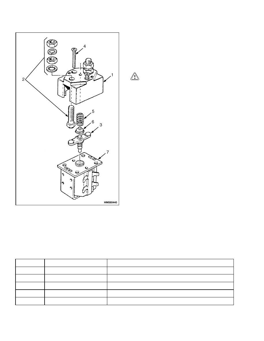
AC Transistor Motor Controller Replacement
2200 SRM 1056
1.
TOP COVER
2.
FIXED CONTACT
SETS
3.
MOVABLE
CONTACTS
4.
SCREW
5.
RETURN SPRING
6.
INSULATOR
7.
COIL ASSEMBLY
Figure 13. Replacement Parts of Power
Steering Contactor
Contactor Contacts. The contacts in a contactor
are made of special silver alloy. The contacts will look
black and rough from normal operation. This condi-
tion does not cause problems with the operation of
the lift truck. Cleaning is not necessary. DO NOT
USE A FILE ON THE CONTACTS. DO NOT LUBRI-
CATE THE CONTACTS.
CAUTION
ALWAYS replace all of the contacts in a con-
tactor at the same time. Replace the contacts
when the thickness of any area of a contact is
less than 30 percent of the thickness of a new
contact or if there is any transfer of contact ma-
terial.
Coil. Check the coil with an ohmmeter for an open
circuit or a short circuit. Coil resistance is very low.
Approximate coil resistance, at room temperature,
can be determined by looking at Status Codes 63,
64, 65, and 69. Replace the coil if it is damaged.
Make sure the coil wires are connected again to the
correct terminals.
NOTE: Some wire numbers found in Table 6, Table 7,
and Table 8 may or may not be followed by a letter,
depending on the lift truck model.
Table 6. 42-Pin Connections/Descriptions for Master Controller
Pin No.
Wire Number
Function
1
2
7
SEAT SWITCH
3
10
KEY SWITCH
4
8
REVERSE SWITCH
5
6
FORWARD SWITCH
38
2200 SRM 1056
AC Transistor Motor Controller Replacement
Table 6. 42-Pin Connections/Descriptions for Master Controller (Continued)
Pin No.
Wire Number
Function
6
32
+12 V
7
13
ANALOG GROUND
8
72
CANbus GROUND
9
51
PUMP HIGH SPEED
10
11*
PUMP LINE CONTACTOR
12
6
FORWARD SIGNAL
13
24
LINE CONTACTOR
14
3
BATTERY POSITIVE
15
65
FAN
16
15
ACC START SWITCH
17
107
PUMP MOTOR BRUSH WEAR
18
108
PUMP MOTOR BRUSH WEAR
19
44
PARK BRAKE
20
21
22
74
CANbus HIGH
23
73
CANbus LOW
24
25
26
27
28
13
BATTERY NEGATIVE
29
SEAT BRAKE
30
31
45
BRAKE FLUID LEVEL
32
100
DC PUMP MOTOR TEMPERATURE
33
53
PUMP LOW SPEED
34
35
36
29
ACCELERATOR PEDAL POSITION
37
38
52
PUMP MEDIUM SPEED
39
39
AC Transistor Motor Controller Replacement
2200 SRM 1056
Table 6. 42-Pin Connections/Descriptions for Master Controller (Continued)
Pin No.
Wire Number
Function
40
54
DC PUMP CONTACTOR
41
8
REVERSE SIGNAL
42
60
POWER STEERING CONTACTOR
*E3.50-5.50XL, E4.50XLS (E70-120Z, E100ZS) (D098) LIFT TRUCK MODELS ONLY
Table 7. Pin Connections/Descriptions for 72/80 (Gen IV) Volt Motor Controllers
Wire Number
Pin No.
Traction
Pump
Function
1
10
10
KEY SWITCH
2
3
33
33
SENSOR VOLTAGE SUPPLY
4
13
13
BATTERY NEGATIVE
5
104
110
SENSOR BEARING SIGNAL
6
103
109
SENSOR BEARING SIGNAL
7
102
100
MOTOR TEMPERATURE
8
9
CONTROLLER ID PIN
10
74
74
CANbus HIGH
11
73
73
CANbus LOW
12
74
CANbus TERMINATION RESISTANCE
13
72
72
CANbus GROUND
Table 8. Pin Connections/Descriptions for 36/48 and 72v/80v (Gen V) Volt Motor Controllers
Wire Number
Pin No.
Traction
Pump
Function
1
10
10
KEY SWITCH
2
3
33
33
SENSOR VOLTAGE SUPPLY
4
13
13
BATTERY NEGATIVE
5
104
110
SENSOR BEARING SIGNAL
6
103
109
SENSOR BEARING SIGNAL
7
72
72
CANbus GROUND
12
CONTROLLER ID PIN
40
2200 SRM 1056
AC Transistor Motor Controller Replacement
Table 8. Pin Connections/Descriptions for 36/48 and 72v/80v (Gen V)
Volt Motor Controllers (Continued)
Wire Number
Pin No.
Traction
Pump
Function
13
13
CONTROLLER ID PIN GROUND
14
73
73
CANbus LOW
15
73
CANbus LOW
16
102
100
MOTOR TEMPERATURE
17
13
13
MOTOR TEMPERATURE GROUND
20
CONTROLLER ID PIN
22
74
74
CANbus HIGH
23
74
CANbus HIGH
THERMAL SENSORS
The thermal sensors for AC motors are embedded in
the motor windings and are continuously monitored
by the motor controllers. They are part of the motor
and cannot be replaced or repaired.
MOTOR CONTROLLER, REPLACE
Make sure the battery is disconnected and the capac-
itor is discharged using the horn as previously de-
scribed. Replace the motor controller as described in
the following procedure.
1.
Make an identification for correct connection of
the power cables on the power terminals of the
motor controller. Disconnect the power cables
and the connector plug for the control wires.
2.
Remove the eight (traction) or six (pump) mount-
ing screws that fasten the plate of the motor con-
troller to the lift truck heat sink. Carefully re-
move the motor controller.
CAUTION
Do not remove the small screws that fasten the
cover of the motor controller.
Make sure there is no dirt between the plate of
the motor controller and the mount surface of
the lift truck heat sink.
3.
Put an even coat of the silicone compound (Hys-
ter P/N 1198757) or equivalent on the plate of
the motor controller. Make sure there are no air
spaces between the plate and mount surface of
the lift truck heat sink. The plate of the motor
controller must make full contact with the heat
sink. Install the mount screws that fasten the
motor controller to the heat sink.
4.
Install the power cables at the power terminals
of the motor controller as identified during re-
moval. Install the connector plug for the control
wires on the connector of the motor controller.
41
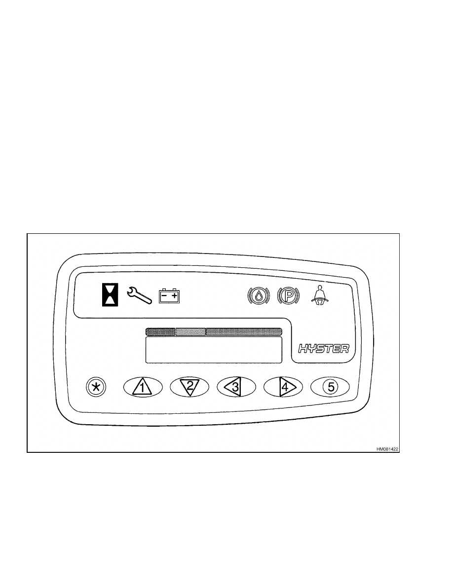
Display Panel
2200 SRM 1056
Display Panel
GENERAL
There are two dash display options, Standard and
Premium.
Both displays look identical.
See Fig-
ure 14.
Premium Display Panel
• Allows preassigned user passwords to control
driver access to the vehicle.
• Provides four driving modes that are accessed
through the key pad.
• Allows preassigned service passwords to control ac-
cess to the service functions available through the
display.
• Provides a comprehensive set of service functions,
which are accessed through the mode buttons and
liquid crystal display (LCD).
• Allows access to the User Check List function.
Standard Display Panel
• Allows preassigned service passwords to control ac-
cess to the service functions available through the
display.
• Provides the same comprehensive set of service
functions using the mode buttons and LCD as the
Premium Display.
Standard and Premium display panels are inter-
changeable on the vehicle. Therefore, the display
system can be easily upgraded or downgraded by
changing the display panel.
Figure 14. Standard and Premium Display Panel
42
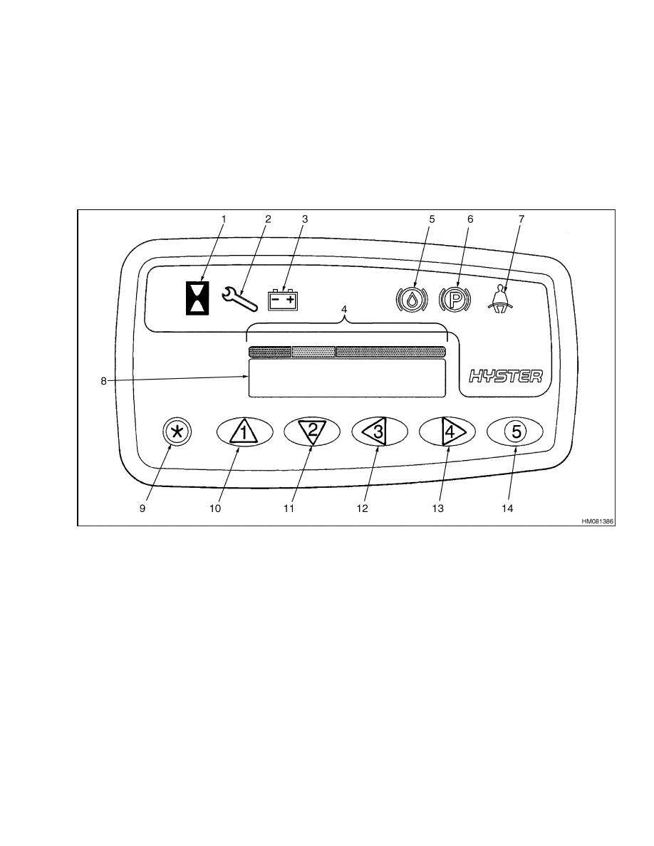
2200 SRM 1056
Display Functions and Features
Display Functions and Features
KEY-ON INITIALIZATION
Upon turning the key to the ON position, the display
sequentially lights the indicators, from left to right,
located along the top of the display. See Figure 15.
NOTE: The seat belt light will stay on whether the
seat belt is fastened or not fastened.
The indicator lights turn off sequentially, except for
the seat belt light, which will remain lighted for ap-
proximately 10 seconds.
1.
HOURMETER INDICATOR
2.
WRENCH INDICATOR
3.
BATTERY INDICATOR
4.
BATTERY DISCHARGE INDICATOR (BDI)
5.
BRAKE FLUID LEVEL
6.
PARKING BRAKE
7.
FASTEN SEAT BELT
8.
LCD SCREEN
9.
STAR PUSH BUTTON
10. PUSH BUTTON #1
11. PUSH BUTTON #2
12. PUSH BUTTON #3
13. PUSH BUTTON #4
14. PUSH BUTTON #5
Figure 15. Dash Display
43
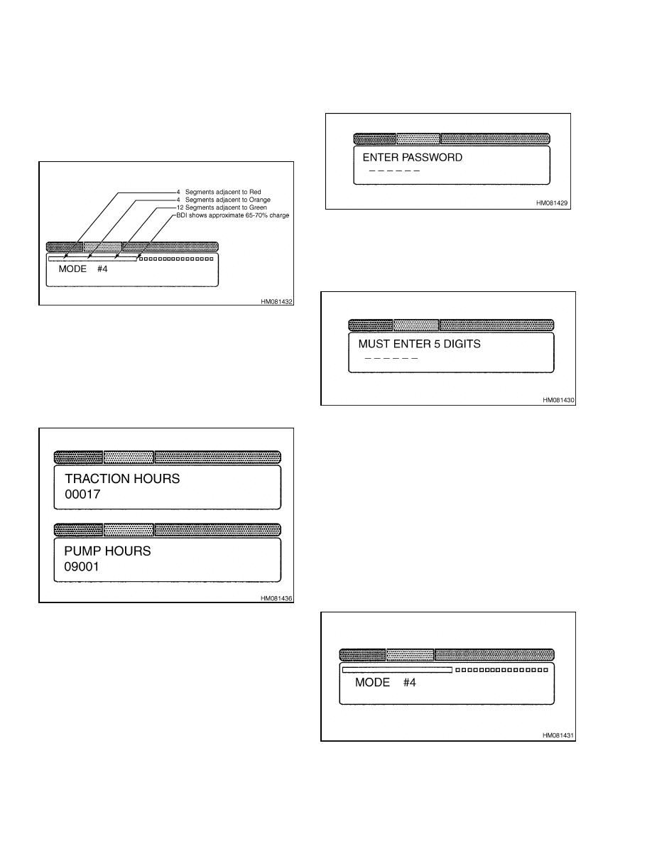
Display Functions and Features
2200 SRM 1056
STANDARD DISPLAY
Following the sequence given above, and as the seat
belt light becomes illuminated, the LCD displays the
BDI as a bar. See Figure 16. As the battery is dis-
charged, the bar becomes shorter.
Figure 16. Battery Discharge Indicator
When the key is turned to the OFF position, the
Hourglass indicator becomes illuminated, and the
following hourmeter information is flashed on the
LCD screen: Traction Hours for 3-4 seconds, followed
by Pump Hours for 3-4 seconds, after which the dis-
play turns off and appears black. See Figure 17.
Figure 17. Traction/Pump Hours
PREMIUM DISPLAY
Following the sequence given above, and as the seat
belt light becomes illuminated, the LCD displays the
prompt for the operator to enter a password if this
function has been enabled. See Figure 18. If the
password function is disabled, the display will by-
pass the password prompt. To enable the password
function, see Troubleshooting and Adjustments
Using the AC Controls Program (ETACC) 2200
SRM 1058, Enable/Disable Password and Lift Truck
Inspection Functions.
Figure 18. Password Prompt Screen
If the password is not entered within 5-8 seconds, a
reminder screen is shown on the LCD display. See
Figure 19.
Figure 19. Password Reminder Screen
Until a password is entered that agrees with a pass-
word stored in the vehicle master controller, the lift
and traction systems are inoperative.
Passwords
may be entered in the master controller using either
the dash display (see Dash Display Service Menu
Navigation) or by using the PC software. See the
section Troubleshooting and Adjustments Us-
ing the AC Controls Program (ETACC) 2200
SRM 1058.
A few seconds after the correct password has been en-
tered, the BDI and performance mode are displayed
and the vehicle can be operated. See Figure 20.
Figure 20. Display Screen (Premium Display)
44
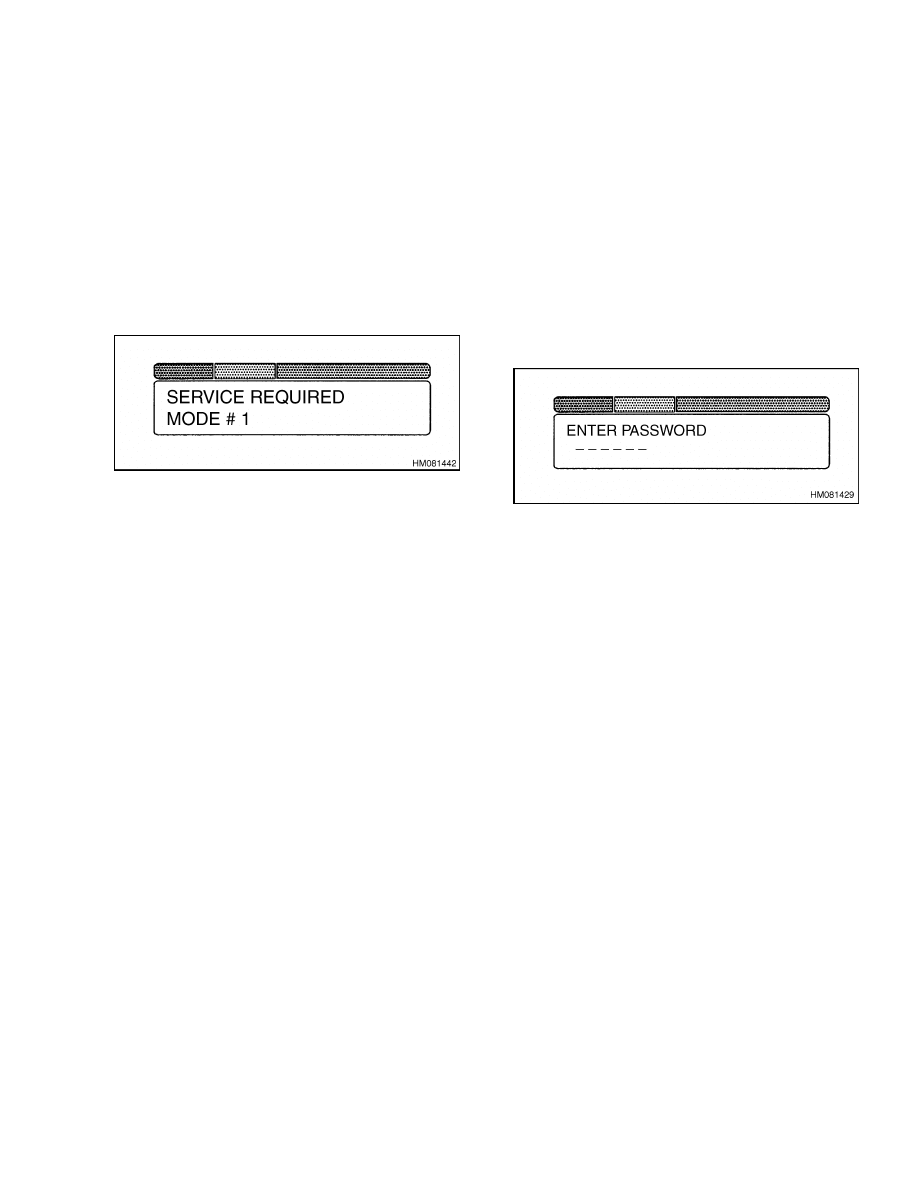
2200 SRM 1056
Display Functions and Features
LIFT TRUCK INSPECTION FUNCTION
If this function is turned on, the operator is prompted
to answer a checklist of questions. The operator in-
dicates a 1 for pass or a 4 for fail. If the operator
indicates the vehicle passes the inspection, the dis-
play will show the previous information and the op-
erator can drive the vehicle. If the operator indicates
that the vehicle fails the inspection, Service Required
will appear on the display screen, and the vehicle will
only operate in Mode 1 until the required action is
taken. See Figure 21.
Figure 21. Inspection Failure Screen
The inspection feature can be enabled with or with-
out the password function enabled, depending upon
the user’s preference. The inspection checklist fea-
ture, as with the password feature, may be set up
using either the dash display or using a PC. For the
PC instructions, go to the section Troubleshooting
and Adjustments Using the AC Controls Pro-
gram (ETACC) 2200 SRM 1058. The checklist must
be enabled or disabled by a service technician.
The following is the list of checks:
• Check for leaks.
• Check service brake.
• Check park brake.
• Check horn, lights, and reverse alarm.
• Check gauges and warning lights.
• Check tire condition and pressure.
• Check hydraulic oil level.
ACCESS TO SERVICE FUNCTIONS
All service functions are accessible from either Stan-
dard or Premium displays. The following functions
are the same with either display version, except as
noted in the following sections.
Once the vehicle is turned ON with the key switch
and the initialization process has been completed, a
service technician can gain access to the service func-
tions by pressing the star button (*) twice.
NOTE: It is suggested that the factory set password,
55555, be changed prior to the lift truck being placed
into service.
The display will prompt the service technician for a
five-digit password. See Figure 22. The default set-
ting for the password is 55555. When a correct pass-
word is entered, the Service Features menu is dis-
played as follows:
• Setup Menu
• Password Menu (Operator passwords are only
available with Premium Display)
• Diagnostic Menu
• View Hourmeter
Figure 22. Password Request
The technician can scroll through the menu using the
up [1] or down [2] arrows and select the desired func-
tion by pressing the [4] button. Each menu selection
has a list of submenu functions. The submenus are
viewed and items selected by scrolling through the
menu in the same manner as described above.
To exit a selected function and return to the previous
function, press the [3] button. Pressing the [3] but-
ton multiple times will return the technician to the
operator’s driving mode.
SERVICE FUNCTIONS
The following submenu functions are accessible
from the Main Menu of Service Functions, described
above.
This includes the following three vehicle
setup values and 16 control function settings. The
16 control function settings are discussed further in
Function Descriptions.
• Setup Menu
Serial Number
Set Traction Hours
Set Pump Hours
Control Function Settings
1.
Battery voltage
2.
Extended Shift
3.
Acceleration 1
4.
Acceleration 2
5.
Top speed limit
45

Display Functions and Features
2200 SRM 1056
6.
Regen braking
7.
Auto deceleration
8.
BDI adjustment
9.
Lift interrupt
10. PS time delay
11. Service reminder
12. Custom
13. Pump speed 1
14. Pump speed 2
15. Pump speed 3
16. Pump acceleration
• Password Menu
Enter Password
Truck Inspection
Add Password
Delete Password
Edit Password
NOTE: All indications in the diagnostic menu are
shown as On, Off, or a value (i.e., Throttle Pot Volt).
On is indicated by a 1. Off is indicated by a 0.
• Diagnostic Menu
No Run Diagnostics
Direction switch
Accelerator start
Throttle pot volt
Seat switch
Park brake
Pump switch #1
Pump switch #2
Pump switch #3
Steering brush #1
Steering brush #2
DC pump brush #1
DC pump brush #2
DC pump motor temp
Fan on
Run Diagnostics
Traction motor speed
Traction motor amps
Traction motor temp
AC pump motor speed
AC pump motor amps
AC pump motor temp
• View Hourmeter
Traction Hourmeter
Pump Hourmeter
Secure Hourmeter
PERFORMANCE MODES
NOTE: Performance modes are not available on the
Standard Dash display, and the factory configuration
is equivalent to Mode 4.
When equipped with the Premium Dash display,
the following four operator-selectable performance
modes are available. These modes are preconfigured
from the factory as described below. Mode 4 provides
the highest performance and Modes 1-3 are percent-
ages of Mode 4. A service technician, using the dash
display or connecting with the PC software, can re-
vise the control settings and configure the top speed
and acceleration of the vehicle.
The relationship
between Modes 1-4 remains constant and cannot be
altered.
With the premium display, the operator can change
modes by pressing the numbered keys on the dash
display. Any number can be selected at any time to
change the performance mode. The change does not
take effect until the operator releases the accelerator
pedal. If the password is enabled, the operator will be
limited by the performance level set in the password
function.
Mode 4 is the highest level of performance available
to the operator, regardless of the performance setup
in the control. For instance, if the control is con-
figured to limit top speed less than maximum, then
Mode 4 top speed is equal to the top speed set in the
control. Three lower performance modes are avail-
able to the operator by using the buttons on the dis-
play. These lower performance settings are percent-
ages of the highest performance available in Mode 4
as described below:
• Mode 4 - This is the highest performance mode.
Other modes are a lower percentage of Mode 4.
• Mode 3 - Top speed is the same as Mode 4. Accel-
eration is 80 percent of Mode 4.
• Mode 2 - Top speed is 80 percent of Mode 4. Accel-
eration is 70 percent of Mode 4.
• Mode 1 - Top speed is 60 percent of Mode 4. Accel-
eration is 60 percent of Mode 4.
BATTERY DISCHARGE INDICATION (BDI)
The AC control system includes a Battery Discharge
Indicator (BDI) that provides indication of the bat-
tery state of charge. See Figure 23. The BDI feature
is displayed to the operator on the dash display with
a 20-segment bar that looks and functions the same
as the current BDI. Lift truck operators will not need
to learn a new BDI system.
46
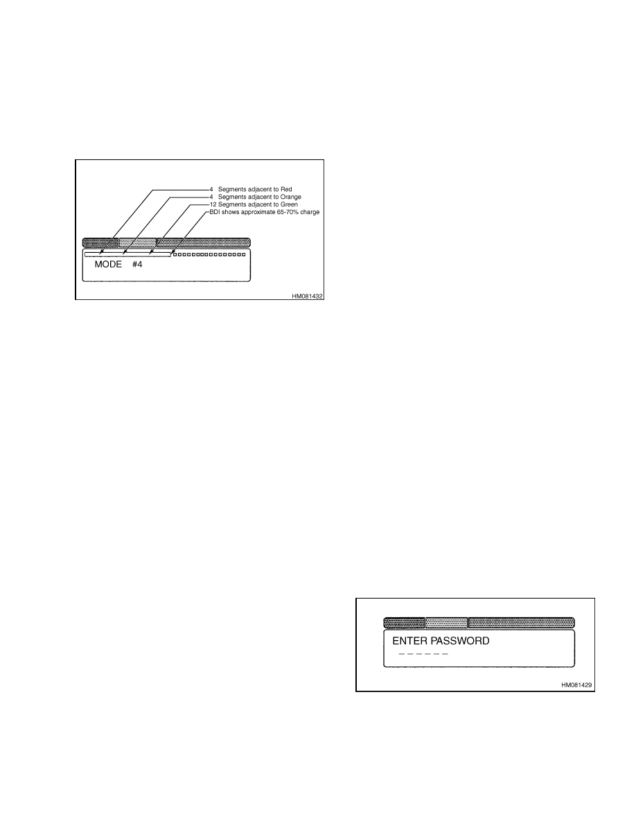
2200 SRM 1056
Dash Display Service Menu Navigation
The BDI provides full functionality when used with
a full range of batteries including:
• Flooded cell, standard amp-hour batteries
• Flooded cell, high amp-hour capacity batteries
• Valve regulated (absorbed glass mat) maintenance-
free batteries (VRLA)
Figure 23. Battery Discharge Indication in
Dash Display LCD Window
The lift interrupt feature is controlled by the vehicle
master controller and prevents the lift function when
the battery is 80 percent discharged. Although lift
interrupt prevents lifting, low speed functions, such
as tilt and sideshift, remain operational to allow the
operator to more easily remove the forks from the
load and return to the battery charging area.
When lift interrupt is initiated, it will remain in ef-
fect until the battery is disconnected and a recharged
battery is reconnected to the vehicle. When a bat-
tery is replaced or recharged, the new state of charge
must be at least 25 percent greater than the previ-
ous state of charge. This prevents the BDI from be-
ing activated by a battery that has recovered slightly
during an idle period.
A BDI adjustment feature is provided through the
control setup function, which is accessible using ei-
ther the dash display or the PC service software. The
adjustment scale is 0-100, with a value of 30 for the
factory setting. The setting of 30 is the starting point
for flooded cell-type batteries of all voltages and amp-
hour capacities. The adjustment can then be used to
fine-tune the BDI lift interrupt feature. For example,
if it is desired to have the lift interrupt to occur at a
higher battery specific gravity, then the value would
be increased. The value is decreased if a lower spe-
cific gravity is desired for the lift interrupt point.
If a maintenance-free battery is installed, the BDI
adjustment should be increased to a value of about
50 as a starting point. Fine-tuning can be done from
that value.
HOURMETER
There are three different hourmeter functions.
1.
Pump hours - accumulates time only when the
pump motor is operating.
2.
Traction hours - accumulates time when the seat
switch is closed and the key switch is in the ON
position.
3.
Secure hours - based on traction hours. The se-
cure hours cannot be reset.
The hourmeter data is stored in the master controller
during every 6 minutes of operation. If there is a loss
of power, data is not lost.
Dash Display Service Menu Navigation
GENERAL
To enter the service mode, turn the key to the ON po-
sition and press the (*) button twice. Enter Password
prompt will appear on the display. See Figure 24. All
lift trucks will have 55555 as the default service pass-
word at the time of delivery. This password can be
changed by a service technician. Go to Editing and
Adding Information.
Figure 24. Password Prompt
47
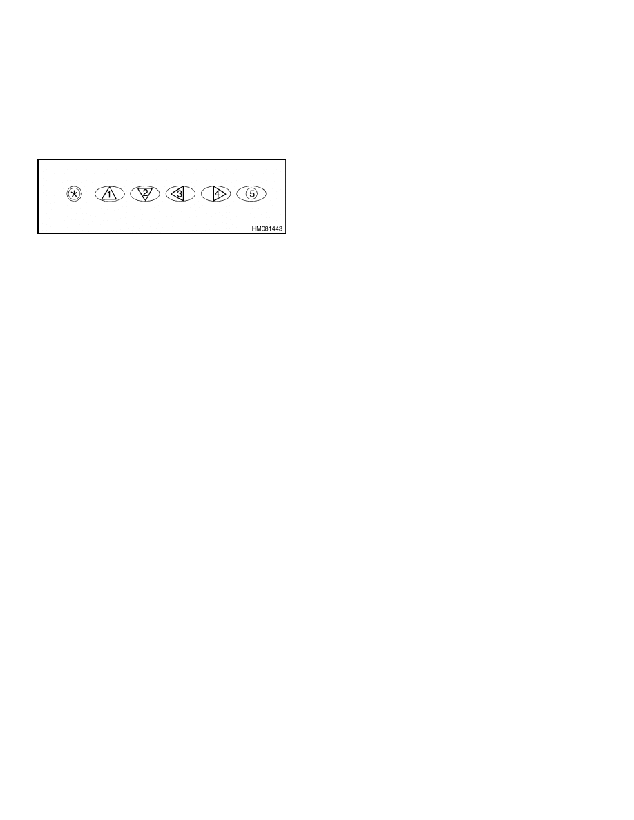
Dash Display Service Menu Navigation
2200 SRM 1056
Buttons [1], [2], [3], [4], and [*] are used for menu
navigation and for adding or editing information.
Button [5] is only used if it is part of the password
required to enter the service mode.
The display
has arrows on the buttons to aid in the navigation
process. See Figure 25.
Figure 25. Dash Display Buttons
The following list is the numbers on the dash display
and their function:
1.
Is up, for scrolling up
2.
Is down, for scrolling down
3.
Is left, for scrolling left or out of the current menu
4.
Is right, for scrolling right or deeper into the next
menu level
MOVING THROUGH MENU SELECTIONS
1.
When the service technician’s password has been
correctly entered, the first menu item, which is
the Setup Menu, is displayed on the dash dis-
play LCD screen. To view the next menu item,
press the [2] key on the dash display numeric key
pad. Repeat this until the desired menu item has
been reached. To return to a previous menu item,
press the [1] key. When the last menu item is
reached and the [2] key is pressed again, the first
menu item will return to the display.
2.
To move into a submenu of a main menu item,
press the [4] key on the dash display numeric key
pad. To move into a sub submenu, as with the
Diagnostics Menu, press the [4] key again.
3.
To move up or down within the submenu or the
sub submenu, press the [1] or [2] keys.
4.
To move out of the sub submenu and return to
the submenu, press the [3] key.
5.
To move out of the submenu and return to the
main menu, press the [3] key.
6.
To exit the service mode, press the [3] key.
EDITING AND ADDING INFORMATION
NOTE: The setup and password menus can be used to
edit or add information to the truck software. When
an item in these menus is selected, the current value
will be displayed. The characters available to be se-
lected from the display are 0-9, A-Z, blank, and dash.
Each line in the display can have no more than 20
characters including blanks.
1.
If a change is to be made, press the [4] key and
the cursor will blink on one of the characters.
Keys [3] and [4] are used to move from character
to character in the item being changed.
2.
When a character that is to be changed is blink-
ing, use keys [1] and [2] to scroll up or down until
the desired character is found. Use keys [3] or [4]
to move to the next character to be changed. This
is repeated until all changes in the item have
been made.
3.
When all changes have been made, press the [*]
key to store the value. Press the [1] or [2] key to
access the next item to be changed. Repeat this
procedure for each item that is to be changed.
4.
When all changes have been made, press the [3]
key to exit the menu.
48


TECHNICAL PUBLICATIONS
2200 SRM 1056
7/05 (3/05)(5/04)(3/04)(1/04)(12/03)(11/03)(3/03) Printed in United Kingdom
Document Outline
- toc
- AC Motor Controllers/Display Panel
- Safety Precautions Maintenance and Repair
- Description
- Master Controller Checks and Adjustments
- Function Settings
- Function Descriptions
- General
- Function Number 1 BATTERY VOLTAGE
- Function Number 2 EXTENDED SHIFT
- Function Number 3 ACCELERATION 1
- Function Number 4 ACCELERATION 2
- Function Number 5 TOP SPEED LIMIT
- Function Number 6 REGEN BRAKING
- Function Number 7 AUTO DECELERATION
- Function Number 8 BDI ADJUSTMENT
- Function Number 9 LIFT INTERRUPT
- Function Number 10 POWER STEERING TIME DELAY
- Function Number 11 SERVICE REMINDER
- Function Number 12 CUSTOM
- Function Number 13 PUMP SPEED 1
- Function Number 14 PUMP SPEED 2
- Function Number 15 PUMP SPEED 3
- Function Number 16 PUMP ACCELERATION
- General
- Troubleshooting
- AC Motor Controllers Status Code Charts
- AC Transistor Motor Controller Replacement
- Display Panel
- Display Functions and Features
- Dash Display Service Menu Navigation
- tables
- Table 1. Factory Parameter Table - J2.00-3.20XM (J40-65Z) (A416)
- Table 2. Factory Setting Table - V30ZMD (D210), E2.00-3.20XM (E4
- Table 3. Factory Setting Table - E1.50-2.00XM (E25-35Z, E40ZS) (
- Table 4. Factory Parameter Table - E3.50-5.50XL, E4.50XLS (E70-1
- Table 5. List of Status Codes
- Table 6. 42-Pin Connections/Descriptions for Master Controller
- Table 7. Pin Connections/Descriptions for 72/80 (Gen IV) Volt Mo
- Table 8. Pin Connections/Descriptions for 36/48 and 72v/80v (Gen
Wyszukiwarka
Podobne podstrony:
1554634 2200SRM1078 (07 2005) UK EN
1468474 2200SRM0756 (07 2005) UK EN
1534732 0620SRM1053 (07 2005) UK EN
1580519 2200SRM1131 (07 2005) UK EN
1534733 1600SRM1054 (07 2005) UK EN
1459370 1600SRM0720 (07 2005) UK EN
1596602 0100SRM1200 (07 2005) UK EN
1586985 2200SRM1178 (03 2005) UK EN
1580518 2200SRM1130 (06 2005) UK EN
897961 2200SRM0647 (03 2005) UK EN
1580521 2200SRM1143 (05 2005) UK EN
1596605 8000SRM1203 (07 2005) UK EN
1595265 2200SRM1204 (01 2005) UK EN
więcej podobnych podstron