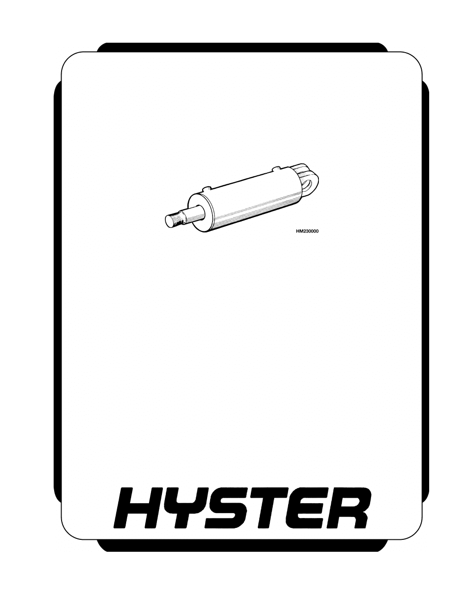
TILT CYLINDERS
H40.00-52.00XM-16CH
(H1050HD-CH, 1150HD-CH) [E117, F117]
PART NO. 1565653
2100 SRM 1116

SAFETY PRECAUTIONS
MAINTENANCE AND REPAIR
• When lifting parts or assemblies, make sure all slings, chains, or cables are correctly
fastened, and that the load being lifted is balanced. Make sure the crane, cables, and
chains have the capacity to support the weight of the load.
• Do not lift heavy parts by hand, use a lifting mechanism.
• Wear safety glasses.
• DISCONNECT THE BATTERY CONNECTOR before doing any maintenance or repair
on electric lift trucks. Disconnect the battery ground cable on internal combustion lift
trucks.
• Always use correct blocks to prevent the unit from rolling or falling. See HOW TO PUT
THE LIFT TRUCK ON BLOCKS in the Operating Manual or the Periodic Mainte-
nance section.
• Keep the unit clean and the working area clean and orderly.
• Use the correct tools for the job.
• Keep the tools clean and in good condition.
• Always use HYSTER APPROVED parts when making repairs. Replacement parts
must meet or exceed the specifications of the original equipment manufacturer.
• Make sure all nuts, bolts, snap rings, and other fastening devices are removed before
using force to remove parts.
• Always fasten a DO NOT OPERATE tag to the controls of the unit when making repairs,
or if the unit needs repairs.
• Be sure to follow the WARNING and CAUTION notes in the instructions.
• Gasoline, Liquid Petroleum Gas (LPG), Compressed Natural Gas (CNG), and Diesel fuel
are flammable. Be sure to follow the necessary safety precautions when handling these
fuels and when working on these fuel systems.
• Batteries generate flammable gas when they are being charged. Keep fire and sparks
away from the area. Make sure the area is well ventilated.
NOTE: The following symbols and words indicate safety information in this
manual:
WARNING
Indicates a condition that can cause immediate death or injury!
CAUTION
Indicates a condition that can cause property damage!

Tilt Cylinders
Table of Contents
TABLE OF CONTENTS
General ...............................................................................................................................................................
Description .........................................................................................................................................................
Tilt Cylinder Repair ...........................................................................................................................................
Remove ...........................................................................................................................................................
Disassemble ...................................................................................................................................................
Clean ..............................................................................................................................................................
Inspect ............................................................................................................................................................
Assemble ........................................................................................................................................................
Install .............................................................................................................................................................
Tilt Cylinder Leak Check ..................................................................................................................................
Tilt Cylinder Stroke and Mast Tilt Angle Adjustment ....................................................................................
Torque Specifications .........................................................................................................................................
Troubleshooting..................................................................................................................................................
This section is for the following models:
H40.00-52.00XM-16CH (H1050HD-CH, 1150HD-CH) [E117, F117]
©2005 HYSTER COMPANY
i

"THE
QUALITY
KEEPERS"
HYSTER
APPROVED
PARTS

2100 SRM 1116
Tilt Cylinder Repair
General
This section has a description, repair, and troubleshooting procedure for the tilt cylinders.
Description
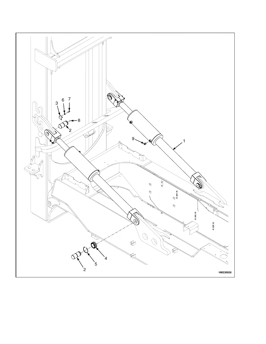
The tilt cylinders (see Figure 1) are used to move the
mast forward and backward. To extend the cylinder
rod (tilt forward), oil enters the tilt cylinder port be-
hind the piston. The oil pressure pushes the cylin-
der rod out of the cylinder. Oil in front of the piston
returns to the hydraulic tank. To retract the cylinder
rod (tilt backward), the oil enters the port in front of
the piston. The oil pressure pushes the cylinder rod
into the tilt cylinder. The oil behind the piston re-
turns to the hydraulic tank.
Tilt Cylinder Repair
REMOVE
WARNING
Remove and replace one tilt cylinder at one
time. Always keep one tilt cylinder assembled
on the lift truck as a safety precaution.
1.
Set the attachment on a container that is at
ground level.
2.
Lock the attachment on the container with the
twistlocks.
3.
Shut down the engine.
4.
Apply the parking brake.
WARNING
Do not disconnect any hydraulic lines when the
engine is running or personal injury may oc-
cur.
5.
Disconnect the hydraulic lines at the tilt cylinder.
Install caps on the hydraulic lines and ports.
WARNING
Do not push the anchor pins out of the rod end
with your fingers. Do not permit the tilt cylin-
ders to drop and cause damage.
6.
Remove the retainers for the anchor pins. Pull
the anchor pin out of the rod end with a pulley.
See Figure 1.
WARNING
The tilt cylinder weights 450 kg (992 lb). Verify
the lifting device has the rated capacity to lift
the tilt cylinder.
7.
Use a lifting device to move large tilt cylinders.
Remove the anchor pins from the frame anchors.
Remove the tilt cylinder from the frame.
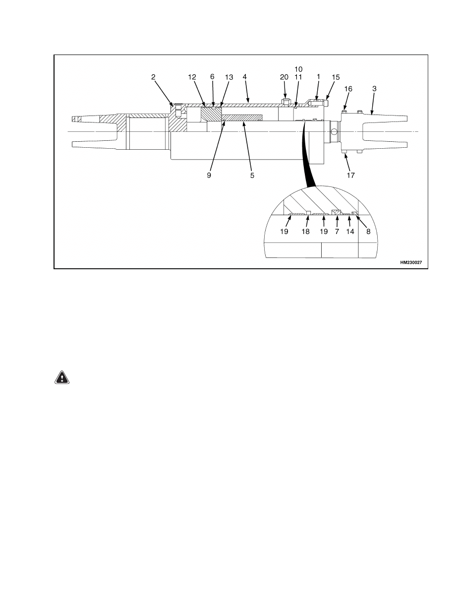
DISASSEMBLE
1.
Put the tilt cylinder in a vise with soft jaws,
placed in a horizontal position.
2.
Disassemble and remove the end rod by remov-
ing the two bolts/nuts. See Figure 2.
3.
Disassemble and remove the bearing from the
piston rod by removing the 20 retaining bolts.
CAUTION
Be careful not to damage the finished surface
of the piston rod when removing the piston rod
from the cylinder shell in a horizontal position
(parallel to the cylinder shell).
4.
Disassemble piston rod assembly from the cylin-
der shell by pulling it out.
CAUTION
Be careful not to damage the grooves when re-
moving seals, wipers, and wear rings.
5.
Disassemble and remove all seals, wipers, and
wear rings.
1
Tilt Cylinder Repair
2100 SRM 1116
1.
TILT CYLINDER
2.
ANCHOR PIN
3.
RETAINER
4.
BEARING
5.
SNAP RING
6.
WASHER
7.
CAPSCREW
8.
SCREW
9.
FITTING
Figure 1. Tilt Cylinder Removal/Installation
2
2100 SRM 1116
Tilt Cylinder Repair
1.
BEARING
2.
PISTON ROD
3.
ROD END
4.
CYLINDER SHELL
5.
SPACER
6.
PISTON SEAL
7.
ROD SEAL
8.
WIPER
9.
O-RING
10. O-RING
11. BACKUP RING
12. WEAR BAND
13. WEAR BAND
14. WEAR BAND
15. BOLT
16. NUT
17. BOLT
18. ROD SEAL
19. WEAR BAND
20. O-RING
Figure 2. Tilt Cylinder
CLEAN
WARNING
Cleaning solvents can be flammable and toxic
and can cause skin irritation.
When using
cleaning solvents, always follow the solvent
manufacturer’s recommended safety proce-
dures.
Compressed air can move particles so they
cause injury to the user or to other personnel.
Make sure that the path of the compressed air
is away from all personnel.
Wear protective
goggles or a face shield to prevent injury to
the eyes.
Clean all parts in solvent and dry with compressed
air.
INSPECT
Inspect the parts of the tilt cylinders for damage,
rust, or wear. Carefully inspect the rod surface for
absence of dents and scratches. Verify that the inter-
nal stroke surface of the cylinder shell and grooves
for the seals do not show any nicks, scratches, or
other damage. Repair or replace parts as needed.
ASSEMBLE
NOTE: Verify that all parts are clean before assembly.
NOTE: Always use new seals and O-rings. Lubricate
all parts with clean hydraulic oil.
1.
Assemble the new seals, wipers, and wear rings
according to Figure 2.
2.
Assemble the bearing onto the piston rod.
3
Tilt Cylinder Stroke and Mast Tilt Angle Adjustment
2100 SRM 1116
CAUTION
Be careful not to damage the finished surface
of the piston rod when installing the piston rod
into the cylinder shell in a horizontal position
(parallel to the cylinder shell).
3.
Lubricate the cylinder shell bore with clean hy-
draulic oil. Push the piston rod assembly into the
cylinder shell.
4.
Push the bearing into the cylinder shell. Lubri-
cate the threads of the cylinder shell and bolts
with clean oil and install the bolts and tighten.
See Torque Specifications.
5.
Assemble the rod end onto the rod. Lubricate the
capscrews with clean oil. Install and tighten the
capscrews. See Torque Specifications.
INSTALL
NOTE: Before installing the tilt cylinder, apply a
pressure test of 25 MPa (3626 psi).
1.
Use a lifting device to move large tilt cylinders.
Put the cylinder in the lift truck. Install the an-
chor pin in the frame. Install the retainer pin.
See Figure 1.
2.
Install the anchor pin at the mast mount. Install
the retainer pin for the anchor pin. Tighten the
capscrews for the retainer pins.
3.
Connect the hydraulic lines to the tilt cylinder.
4.
Operate the tilt cylinders. Check for correct op-
eration and leakage. Adjust the tilt cylinders
as described in Tilt Cylinder Leak Check and
Tilt Cylinder Stroke and Mast Tilt Angle Adjust-
ment.
Tilt Cylinder Leak Check
WARNING
Never allow anyone under a raised carriage.
Do not put any part of your body in or through
the lift mechanism unless all parts of the mast
are completely lowered and the engine is
STOPPED.
Do not try to find hydraulic leaks by putting
your hand on hydraulic components under
pressure.
Hydraulic oil can be injected into
the body by the pressure.
1.
Put a capacity load on the forks. Use a safety
chain to hold the load to the carriage. Raise the
load approximately 2.5 m (8 ft). Put the mast in
a vertical position.
2.
Measure the distance that the rod for tilt cylinder
extends from the shell. Check the distance the
rod moves in ten minutes. See the rate in Table 1.
3.
If the tilt rate is greater than the specifications,
lower the mast and remove the load from the
forks. Install a valve between the port at the
front of the tilt cylinder and the hydraulic line.
Put the load on the forks again. Close the valve.
Tilt the mast forward just past the vertical posi-
tion. If the mast continues to tilt slowly forward,
the seals on the piston are leaking.
4.
If the mast does not move, open the gate valve
and check the movement again.
If the mast
moves forward when the gate valve is open,
check for leaks in the hydraulic lines and fit-
tings. If no leaks are found, the main control
valve can be worn or damaged. Remove the load
from the forks when the checks are complete.
Table 1. Movement Rate (Maximum)
for Tilt Cylinders
Hydraulic Oil Temperature/Mast Tilt Rate
60 C (140 F)
mm/10 min
in./10 min
12.7
0.5
Tilt Cylinder Stroke and Mast Tilt Angle Adjustment
Adjust the tilt cylinders as described in the section Mast 4000 SRM 1160.
4

2100 SRM 1116
Troubleshooting
Torque Specifications
Piston Rod End Nut
333 N•m (245 lbf ft)
Bearing Bolt
649 N•m (480 lbf ft)
Troubleshooting
PROBLEM
POSSIBLE CAUSE
PROCEDURE OR ACTION
Tilt cylinder movement is
slow or not smooth.
Air is in the hydraulic system.
Remove air from hydraulic system.
The hydraulic pump is worn or dam-
aged.
Repair or replace hydraulic pump.
Restriction in the hydraulic lines.
Repair hydraulic lines.
Seals in tilt cylinder are damaged.
Replace seals and inspect cylinder
bore for damage.
Tilt cylinders have internal damage.
Repair or replace cylinder.
Load is greater than capacity.
Reduce load.
Pressure relief valve(s) is not ad-
justed correctly or is damaged.
Repair or adjust relief valve(s).
Large leaks between spool and bore.
Replace valve section.
Spool is not fully extended or re-
tracted.
Adjust linkage to spool.
Tilt control spool is damaged.
Repair control valve.
The tilt cylinders permit the
mast to move when the Tilt
control lever is in the Neu-
tral position.
There are leaks in the hydraulic
lines.
Tighten fittings or repair leaks.
Seals in tilt cylinder are damaged.
Replace seals and inspect cylinder
bore for damage.
Tilt cylinders have internal damage.
Repair or replace cylinder.
Tilt control spool is damaged.
Repair control valve.
5

NOTES
____________________________________________________________
____________________________________________________________
____________________________________________________________
____________________________________________________________
____________________________________________________________
____________________________________________________________
____________________________________________________________
____________________________________________________________
____________________________________________________________
____________________________________________________________
____________________________________________________________
____________________________________________________________
____________________________________________________________
____________________________________________________________
____________________________________________________________
____________________________________________________________
____________________________________________________________
____________________________________________________________
____________________________________________________________
____________________________________________________________
6


TECHNICAL PUBLICATIONS
2100 SRM 1116
8/05 (8/04)(7/04) Printed in United Kingdom
Document Outline
Wyszukiwarka
Podobne podstrony:
1568204 0700SRM1159 (08 2005) UK EN
1566043 0620SRM1115 (08 2005) UK EN
910091 1900SRM0097 (08 2005) UK EN
1565789 1800SRM1117 (08 2005) UK EN
1569718 4000SRM1160 (08 2005) UK EN
1529749 1800SRM1036 (08 2005) UK EN
1574068 1400SRM1171 (08 2005) UK EN
1580516 2100SRM1139 (09 2005) UK EN
1596604 8000SRM1202 (08 2005) UK EN(1)
1568204 0700SRM1159 (08 2005) UK EN
1566043 0620SRM1115 (08 2005) UK EN
więcej podobnych podstron