CAPACITIES AND
SPECIFICATIONS
E3.50-5.50XL, E4.50XLS
(E70-120Z, E100ZS) [D098]
PART NO. 1596604
8000 SRM 1202

SAFETY PRECAUTIONS
MAINTENANCE AND REPAIR
• When lifting parts or assemblies, make sure all slings, chains, or cables are correctly
fastened, and that the load being lifted is balanced. Make sure the crane, cables, and
chains have the capacity to support the weight of the load.
• Do not lift heavy parts by hand, use a lifting mechanism.
• Wear safety glasses.
• DISCONNECT THE BATTERY CONNECTOR before doing any maintenance or repair
on electric lift trucks. Disconnect the battery ground cable on internal combustion lift
trucks.
• Always use correct blocks to prevent the unit from rolling or falling. See HOW TO PUT
THE LIFT TRUCK ON BLOCKS in the Operating Manual or the Periodic Mainte-
nance section.
• Keep the unit clean and the working area clean and orderly.
• Use the correct tools for the job.
• Keep the tools clean and in good condition.
• Always use HYSTER APPROVED parts when making repairs. Replacement parts
must meet or exceed the specifications of the original equipment manufacturer.
• Make sure all nuts, bolts, snap rings, and other fastening devices are removed before
using force to remove parts.
• Always fasten a DO NOT OPERATE tag to the controls of the unit when making repairs,
or if the unit needs repairs.
• Be sure to follow the WARNING and CAUTION notes in the instructions.
• Gasoline, Liquid Petroleum Gas (LPG), Compressed Natural Gas (CNG), and Diesel fuel
are flammable. Be sure to follow the necessary safety precautions when handling these
fuels and when working on these fuel systems.
• Batteries generate flammable gas when they are being charged. Keep fire and sparks
away from the area. Make sure the area is well ventilated.
NOTE: The following symbols and words indicate safety information in this
manual:
WARNING
Indicates a condition that can cause immediate death or injury!
CAUTION
Indicates a condition that can cause property damage!

Capacities and Specifications
Table of Contents
TABLE OF CONTENTS
Lift Truck Lifting Capacity................................................................................................................................
Counterweight Weights .....................................................................................................................................
Tire Sizes ............................................................................................................................................................
Capacities ...........................................................................................................................................................
Hydraulic System...............................................................................................................................................
Steering System .................................................................................................................................................
Specifications .................................................................................................................................................
Turning Radius ..............................................................................................................................................
Mast Speeds .......................................................................................................................................................
Maximum Carriage and Tilt Creep Rates ........................................................................................................
Battery Specifications........................................................................................................................................
Traction Motor Speed.........................................................................................................................................
Battery Current at Hoist Relief ........................................................................................................................
Torque Specifications .........................................................................................................................................
Brake System.................................................................................................................................................
Differential.....................................................................................................................................................
Drive Axle ......................................................................................................................................................
Frame .............................................................................................................................................................
Mast................................................................................................................................................................
Main Control Valve........................................................................................................................................
Steering System.............................................................................................................................................
Tilt Cylinders .................................................................................................................................................
Hydraulic System ..........................................................................................................................................
Electrical System ...........................................................................................................................................
This section is for the following models:
E3.50-5.50XL, E4.50XLS (E70-120Z, E100ZS) [D098]
©2005 HYSTER COMPANY
i

"THE
QUALITY
KEEPERS"
HYSTER
APPROVED
PARTS

8000 SRM 1202
Capacities
Lift Truck Lifting Capacity
Model
Kilograms (Pounds)
E3.50XL (E70Z)
3175 kg (7000 lb)
E4.00XL (E80Z)
3628 kg (8000 lb)
E4.50XLS (E100ZS)
4536 kg (10,000 lb)
E4.50XL (E100Z)
4536 kg (10,000 lb)
E5.50XL (E120Z)
5443 kg (12,000 lb)
NOTE: Load center at 610 mm (24 in.)
Counterweight Weights
Model
Kilograms (Pounds)*
E3.50XL (E70Z)
822 kg (1812 lb)
E4.00XL (E80Z)
1253 kg (2762 lb)
E4.50XLS (E100ZS)
1912 kg (4215 lb)
E4.50XL (E100Z)
1253 kg (2762 lb)
E5.50XL (E120Z)
1912 kg (4215 lb)
* ±50 kg (110 lb)
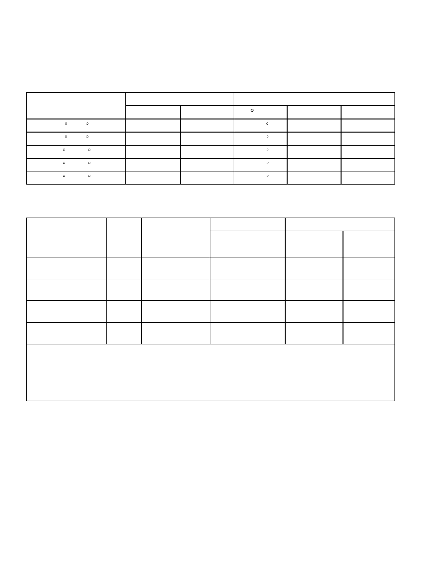
Tire Sizes
Model
Steering
Drive
E3.50-4.00XL (E70-80Z)
18 × 6 × 12-1/8
22 × 9 × 16
E4.50-5.50XL, E4.50XLS
(E100-120Z, E100ZS)
18 × 7 × 12-1/8
22 × 12 × 16
Capacities
Item
Specification
Hydraulic System Capacity
E3.50XL, E4.00XL, E4.50XLS (E70Z, E80Z, E100ZS)
41.3 liter (10.9 gal)
E4.50XL, E5.50XL (E100Z, E120Z)
49.2 liter (13.0 gal)
Hydraulic Tank Capacity (To Full Mark)
E3.50XL, E4.00XL, E4.50XLS (E70Z, E80Z, E100ZS)
33.3 liter (8.8 gal)
E4.50XL, E5.50XL (E100Z, E120Z)
39.8 liter (10.5 gal)
Differential/Speed Reducer
5.2 liter (5.5 qt)
Brake Fluid
0.24 liter (0.5 pt)
1

Steering System
8000 SRM 1202
Hydraulic System
Item
Specification
Relief Pressures*
Main Control Valve
Lift Circuit
20.6 ±0.7 MPa (3000 ±100 psi)
Tilt Circuit
15.5 ±0.7 MPa (2250 ±100 psi)
Steering Circuit
10.3 ±0.35 MPa (1500 ±50 psi)
* Oil temperature 55 to 65 C (130 to 150 F).
Steering System
SPECIFICATIONS
Item
36 Volt
48/80 Volts
Steering Oil Temperature
49 to 60 C (120 to 140 F)
49 to 60 C (120 to 140 F)
Inside Tire Angle
79
79
Number of Turns on Steer Wheel
4.5
4.5
Steering Relief Pressure
10,342 ±345 kPa (1500 ±50 psi)
10,342 ±345 kPa (1500 ±50 psi)
Steering Relief Current
18.4 ±5.0 Amps
18.3 ±5.0 Amps (48 Volt)
11.5 ±5.0 Amps (80 Volt)
Open Center Pressure Maximum
345 kPa (50 psi) Max.
345 kPa (50 psi) Max.
Open Center Current Maximum
3.0 Amps Max.
3.0 Amps Max. (48 Volt)
2.0 Amps Max. (80 Volt)
Steering Time
(Unloaded Static)
3.6 Seconds
2.9 Seconds (48 Volt)
3.0 Seconds (80 Volt)
Hand Pump Displacement
(Nominal)
100 CC/Rev.
100 CC/Rev.
TURNING RADIUS
Model
Turning Radius
E3.50XL (E70Z)
2098 mm (82.6 in.)
E4.00XL (E80Z)
2148 mm (84.6 in.)
E4.50XLS (E100ZS)
2225 mm (87.6 in.)
E4.50XL (E100Z)
2314 mm (91.1 in.)
E5.50XL (E120Z)
2405 mm (94.7 in.)
Minimum Turing Radius Average Values ±50 mm (±2 in.)
(WITH LOAD)
2

8000 SRM 1202
Mast Speeds
Mast Speeds
Lifting
Lowering
Rated Load
No Load
Rated Load
No Load
Model
Mast
V
m/sec
ft/min
m/sec
ft/min
m/sec ft/min m/sec
ft/min
Two-Stage
36
48/80
0.27
0.38
54
76
0.46
0.59
91
118
0.52
104
0.48
95
Free-Lift
36
48/80
0.26
0.36
51
71
0.44
0.55
84
109
0.45
90
0.37
74
E3.50XL
(E70Z)
Three-Stage
36
48/80
0.26
0.36
51
72
0.43
0.53
86
106
0.49
98
0.39
77
Two-Stage
36
48/80
0.26
0.37
52
73
0.46
0.59
91
118
0.52
104
0.48
95
Free-Lift
36
48/80
0.25
0.34
49
68
0.42
0.55
84
109
0.45
90
0.37
74
E4.00XL
(E80Z)
Three-Stage
36
48/80
0.25
0.35
49
69
0.43
0.53
86
106
0.49
98
0.39
77
Two-Stage
36
48/80
0.20
0.29
40
57
0.35
0.45
69
89
0.45
89
0.37
73
Free-Lift
36
48/80
0.20
0.27
39
54
0.32
0.41
64
82
0.40
80
0.29
58
E4.50XL,
E4.50XLS
(E100Z,
E100ZS)
Three-Stage
36
48/80
0.20
0.27
39
54
0.35
0.40
64
80
0.43
86
0.32
63
Two-Stage
36
48/80
0.19
0.27
38
53
0.35
0.45
69
89
0.45
89
0.37
73
Free-Lift
36
48/80
0.18
0.25
36
50
0.32
0.41
64
82
0.40
80
0.29
58
E5.50XL
(E120Z)
Three-Stage
36
48/80
0.18
0.25
36
50
0.32
0.40
64
80
0.44
88
0.32
63
Oil temperature 55 to 66 C (130 to 150 F). Lifting speeds (valve fully open) ±10% acceptable. "No Load"
lowering speeds are minimum values. "Rated Load" lowering speeds are maximum values.
3
Battery Specifications
8000 SRM 1202
Maximum Carriage and Tilt Creep Rates
NOTE: Start measurement with mast at vertical position and the load raised to 2.5 m (8.2 ft). Use maximum
lift height if the maximum is less than 2.5 m (8.2 ft).
Vertical Creep at Carriage
Tilt Creep at Cylinder Rod
Hydraulic Oil
Temperature
mm/Min
in./Min
/Min
mm/Min
in./Min
20 C (68 F)
2.2 mm
0.09 in.
0.11
0.74 mm
0.029 in.
30 C (86 F)
4.2 mm
0.17 in.
0.21
1.42 mm
0.54 in.
40 C (104 F)
6.3 mm
0.25 in.
0.31
2.10 mm
0.83 in.
50 C (122 F)
10.0 mm
0.39 in.
0.50
3.38 mm
1.33 in.
60 C (140 F)
14.6 mm
0.57 in.
0.73
4.94 mm
1.94 in.
Battery Specifications
Battery Length*
Weight
Model
Volts
Minimum
Compartment
Size Length ×
Width
Min./Max
Min.
Max.
E3.50-4.00XL
(E70-80Z)
36, 48,
80
841 × 987 mm
(33.1 × 38.9 in.)
950 to 990 mm
(37.4 to 39.0 in.)
1542 kg
(3400 lb)
2177 kg
(4799 lb)
E4.50XLS (E100ZS)
36, 48,
80
841 × 987 mm
(33.1 × 38.9 in.)
950 to 990 mm
(37.4 to 39.0 in.)
1633 kg
(3600 lb)
2177 kg
(4799 lb)
E4.50XL (E100Z)
36, 48,
80
694 × 1037 mm
(27.3 × 40.8 in.)
1115 to 1150 mm
(43.9 to 45.3 in.)
1814 kg
(4000 lb)
2517 kg
(5681 lb)
E5.50XL (E120Z)
36, 48,
80
993 × 1146 mm
(39.3 × 45.1 in.)
1115 to 1150 mm
(43.9 to 45.3 in.)
1919 kg
(4231 lb)
2517 kg
(5681 lb)
*BATTERY WIDTH
Batteries without cover: 950 to 1117 mm (37.4 to 44.0 in.)
Batteries with cover: 950 to 1143 mm (37.4 to 45.0 in.)
NOTE: Maximum tolerances are +0 and -13 mm (+0 and -0.5 in.) for the size of the battery compartment. The
battery specification chart shows the maximum size tolerances that will permit the battery to still fit into a
battery compartment.
4
8000 SRM 1202
Torque Specifications
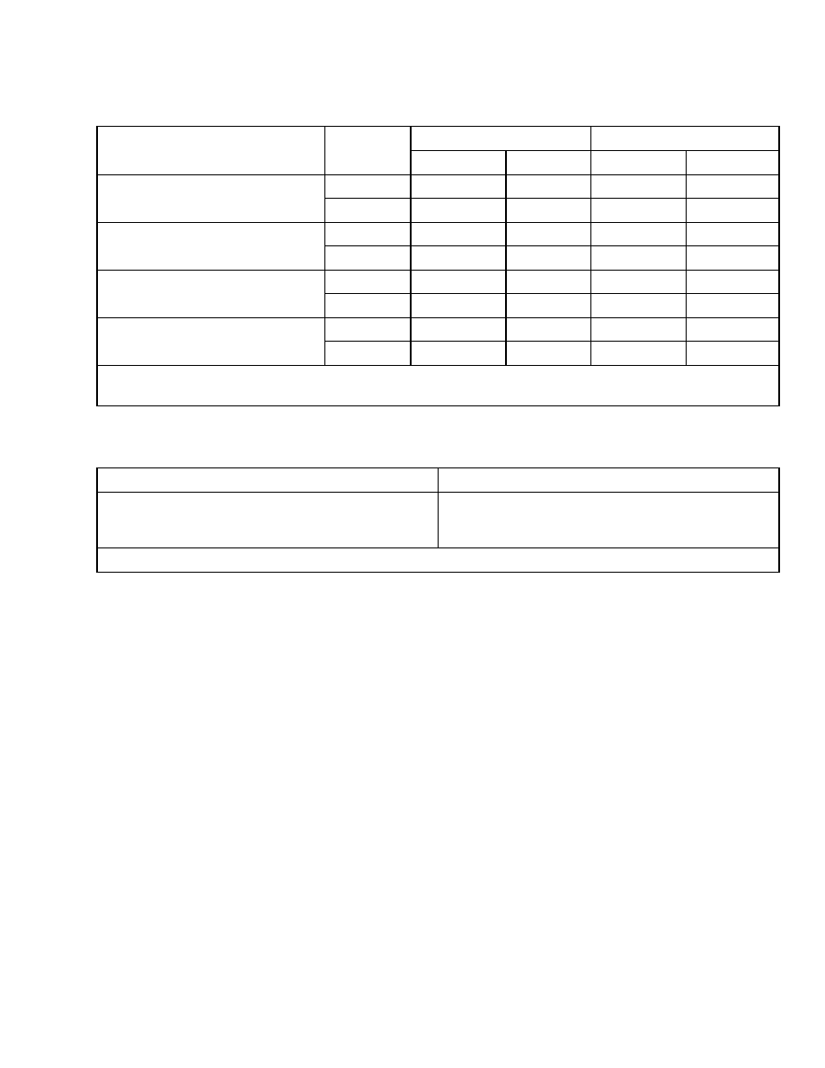
Traction Motor Speed
No Load
Rated Load
Model
Volts
km/h
mph
km/h
mph
36
12.0
7.5
10.9
6.8
E3.50XL(E70Z)
48/80
13.8
8.6
13.2
8.2
36
11.7
7.3
10.5
6.5
E4.00XL(E80Z)
48/80
13.8
8.6
12.7
7.9
36
11.4
7.1
9.9
6.2
E4.50XLS (E100ZS)
E4.50XL (E100Z)
48/80
13.7
8.5
12.0
7.5
36
11.2
7.0
9.7
6.0
E5.50XL (E120Z)
48/80
13.3
8.3
11.6
7.2
NOTE: Speeds ±8% acceptable.
Speeds measured with fully charged battery and lift truck run for one-half hour.
Battery Current at Hoist Relief
Voltage
Battery Current*
36
48
80
782 amps
728 amps
386 amps
*Battery Current at Hoist Relief ±50 amperes.
Torque Specifications
BRAKE SYSTEM
Back Plate Nuts
120 N•m (90 lbf ft)
Brake Drum to Hub Nuts
285 N•m (210 lbf ft)
Service Brakes Support Plate
55 to 80 N•m (40 to 60 lbf ft)
Brake Light Switch Mounting Capscrews
2.0 to 2.3 N•m (18 to 20 lbf in)
DIFFERENTIAL
Lock Plate Capscrews
19 N•m (14 lbf ft)
Adjuster Nuts
40 N•m (30 lbf ft)
Bearing Cap Capscrews
225 N•m (166 lbf ft)
Differential Case Half Capscrews
140 N•m (105 lbf ft)
Ring Gear Capscrews
140 N•m (105 lbf ft)
DRIVE AXLE
Drive Axle to Speed Reducer Case Capscrews
66 N•m (50 lbf ft)
Axle Mount Capscrews
320 N•m (235 lbf ft)
Axle Shaft Capscrews
225 N•m (166 lbf ft)
Wheel Nuts
680 N•m (500 lbf ft)
5

Torque Specifications
8000 SRM 1202
Wheel Bearing Adjustment Nut
203 N•m (150 lbf ft) Initial
34 N•m (25 lbf ft) Final
Wheel Bearing Lock Nut
136 N•m (100 lbf ft)
Traction Motor to Speed Reducer
38 N•m (28 lbf ft)
FRAME
Counterweight Capscrews
Upper 404 N•m (298 lbf ft)
Lower 66 N•m (49 lbf ft)
Overhead Guard Mounting Capscrews
86 N•m (64 lbf ft)
Hood Hinge
8 N•m (71 lbf in)
MAST
Hanger Caps for Sideshift Carriage
320 N•m (235 lbf ft)
Keeper Plate Capscrews
90 N•m (65 lbf ft)
Side Roller Mount Capscrews
90 N•m (65 lbf ft)
Mobile Frame to Fixed Frame, Sideshift
Carriage
78 N•m (58 lbf ft)
Bottom Mounting Capscrews, Main Lift
Cylinders (2 Stage LFL and 3 Stage FFL Masts)
38 N•m (28 lbf ft)
Bottom Mounting Capscrews, Main Lift
Cylinders (2 Stage FFL Masts)
53 N•m (40 lbf ft)
Main Lift Cylinders Mounting Brackets to
Top of Outer Weldment (All Masts)
18 N•m (159 lbf in)
Lowering Control Valve
18 N•m (159 lbf in)
MAIN CONTROL VALVE
Through Bolt Nuts (5/16 in.)
20 N•m (15 lbf ft)
Through Bolt Nuts (3/8 in.)
45 N•m (35 lbf ft)
Solenoid End Plate
4.5 to 5.6 N•m (40 to 50 lbf in)
STEERING SYSTEM
Axle Mount Capscrews
88 N•m (65 lbf ft)
Bearing Cap for Spindles
52 N•m (38 lbf ft)
Tie Rod Nut
175 N•m (129 lbf ft)
Steering Cylinder Capscrews
225 N•m (165 lbf ft)
Wheel Bearing Adjustment Nut
68 N•m (50 lbf ft) Initial
3 N•m (25 lbf in) Final
Steering Wheel Nut
35 to 45 N•m (26 to 33 lbf ft)
TILT CYLINDERS
Piston Nut
400 to 445 N•m (295 to 325 lbf ft)
Retainer
400 to 500 N•m (295 to 370 lbf ft)
Rod End Lock Capscrews
80 N•m (60 lbf ft)
Anchor Pin Retainer Capscrews
80 N•m (60 lbf ft)
Tilt Cylinder to Mast Mounting
77 N•m (57 lbf ft)
HYDRAULIC SYSTEM
Hydraulic Pump Rear Valve Hous-
ing Capscrews
46 to 49 N•m (34 to 36 lbf ft)
Hydraulic Motor Power Cables
18 to 22 N•m (159.3 to 195 lbf in)
Hydraulic Pump Hose Connections
49 N•m (36 lbf ft)
Steering Motor Power Cables (M6 x 1.0)
6.5 to 7.0 N•m (57.5 to 62 lbf in)
6

8000 SRM 1202
Torque Specifications
Steer Pump Hose Connections
77 to 80 N•m (56 to 59 lbf ft)
Steering and Hydraulic Pump and Motor
Mounting Bracket Capscrews
16 N•m (142 lbf in)
ELECTRICAL SYSTEM
Electrical Connections:
#6-32 - Terminal Strip
0.73 to 1.02 N•m (6.5 to 9.0 lbf in)
M6 x 1.00 - Power Steer Motor
4.7 to 5.3 N•m (42 to 47 lbf in)
M8 x 1.00 - Traction and Pump Motor
21 to 25 N•m (186 to 221 lbf in)
M8 x 1.00 - Traction and Pump Controls
13 to 17 N•m (115 to 150 lbf in)
M10 x 1.5 - Line and Pump Contactors
15 to 18 N•m (133 to 159 lbf in)
Traction and Pump Motor Controllers
26 to 28 N•m (230 to 248 lbf in)
7

NOTES
____________________________________________________________
____________________________________________________________
____________________________________________________________
____________________________________________________________
____________________________________________________________
____________________________________________________________
____________________________________________________________
____________________________________________________________
____________________________________________________________
____________________________________________________________
____________________________________________________________
____________________________________________________________
____________________________________________________________
____________________________________________________________
____________________________________________________________
____________________________________________________________
____________________________________________________________
____________________________________________________________
____________________________________________________________
____________________________________________________________
8


TECHNICAL PUBLICATIONS
8000 SRM 1202
8/05 (7/05)(3/05) Printed in United Kingdom
Document Outline
- toc
- Capacities and Specifications
- Safety Precautions Maintenance and Repair
- Lift Truck Lifting Capacity
- Counterweight Weights
- Tire Sizes
- Capacities
- Hydraulic System
- Steering System
- Mast Speeds
- Maximum Carriage and Tilt Creep Rates
- Battery Specifications
- Traction Motor Speed
- Battery Current at Hoist Relief
- Torque Specifications
Wyszukiwarka
Podobne podstrony:
1596605 8000SRM1203 (07 2005) UK EN
1510478 8000SRM0988 (06 2005) UK EN
1568204 0700SRM1159 (08 2005) UK EN
1566043 0620SRM1115 (08 2005) UK EN
910091 1900SRM0097 (08 2005) UK EN
1596602 0100SRM1200 (07 2005) UK EN
1565789 1800SRM1117 (08 2005) UK EN
1566279 8000SRM1155 (02 2005) UK EN
1569718 4000SRM1160 (08 2005) UK EN
1529749 1800SRM1036 (08 2005) UK EN
1574068 1400SRM1171 (08 2005) UK EN
897875 8000SRM0616 (03 2005) UK EN
1580526 8000SRM1151 (05 2005) UK EN
1565653 2100SRM1116 (08 2005) UK EN
1495208 8000SRM0949 (03 2005) UK EN
1458783 8000SRM0592 (03 2005) UK EN
więcej podobnych podstron