MAST
H40.00-52.00XM-16CH
(H1050HD-CH, 1150HD-CH) [E117, F117]
PART NO. 1569718
4000 SRM 1160

SAFETY PRECAUTIONS
MAINTENANCE AND REPAIR
• When lifting parts or assemblies, make sure all slings, chains, or cables are correctly
fastened, and that the load being lifted is balanced. Make sure the crane, cables, and
chains have the capacity to support the weight of the load.
• Do not lift heavy parts by hand, use a lifting mechanism.
• Wear safety glasses.
• DISCONNECT THE BATTERY CONNECTOR before doing any maintenance or repair
on electric lift trucks. Disconnect the battery ground cable on internal combustion lift
trucks.
• Always use correct blocks to prevent the unit from rolling or falling. See HOW TO PUT
THE LIFT TRUCK ON BLOCKS in the Operating Manual or the Periodic Mainte-
nance section.
• Keep the unit clean and the working area clean and orderly.
• Use the correct tools for the job.
• Keep the tools clean and in good condition.
• Always use HYSTER APPROVED parts when making repairs. Replacement parts
must meet or exceed the specifications of the original equipment manufacturer.
• Make sure all nuts, bolts, snap rings, and other fastening devices are removed before
using force to remove parts.
• Always fasten a DO NOT OPERATE tag to the controls of the unit when making repairs,
or if the unit needs repairs.
• Be sure to follow the WARNING and CAUTION notes in the instructions.
• Gasoline, Liquid Petroleum Gas (LPG), Compressed Natural Gas (CNG), and Diesel fuel
are flammable. Be sure to follow the necessary safety precautions when handling these
fuels and when working on these fuel systems.
• Batteries generate flammable gas when they are being charged. Keep fire and sparks
away from the area. Make sure the area is well ventilated.
NOTE: The following symbols and words indicate safety information in this
manual:
WARNING
Indicates a condition that can cause immediate death or injury!
CAUTION
Indicates a condition that can cause property damage!
Mast
Table of Contents
TABLE OF CONTENTS
General ...............................................................................................................................................................
Description and Operation ................................................................................................................................
General ...........................................................................................................................................................
Lifting.............................................................................................................................................................
Lowering.........................................................................................................................................................
Safety Procedures When Working Near Mast..................................................................................................
Carriage Repair..................................................................................................................................................
General ...........................................................................................................................................................
Remove ...........................................................................................................................................................
Disassemble ...................................................................................................................................................
Clean and Inspect ..........................................................................................................................................
Assemble ........................................................................................................................................................
Install .............................................................................................................................................................
Carriage Side Blocks .....................................................................................................................................
Adjust .........................................................................................................................................................
Mast Repair ........................................................................................................................................................
Remove ...........................................................................................................................................................
Disassemble ...................................................................................................................................................
Clean and Inspect ..........................................................................................................................................
Assemble ........................................................................................................................................................
Install .............................................................................................................................................................
Lift Cylinders Repair .........................................................................................................................................
Remove ...........................................................................................................................................................
Disassemble ...................................................................................................................................................
Clean and Inspect ..........................................................................................................................................
Assemble ........................................................................................................................................................
Install .............................................................................................................................................................
Header Hoses Replacement...............................................................................................................................
Carriage Side Blocks Adjustment .....................................................................................................................
Mast Side Blocks Adjustment ...........................................................................................................................
Mast Load Rollers Adjustment .........................................................................................................................
Lift Chains Adjustment .....................................................................................................................................
Lift and Tilt Cylinders Leak Check ..................................................................................................................
Troubleshooting..................................................................................................................................................
This section is for the following models:
H40.00-52.00XM-16CH (H1050HD-CH, 1150HD-CH) [E117, F117]
©2005 HYSTER COMPANY
i

"THE
QUALITY
KEEPERS"
HYSTER
APPROVED
PARTS
4000 SRM 1160
Description and Operation
General
This section has the description and the service procedures for the mast. The parts of the mast include the
forks, carriages, lift cylinders, and the mast weldments.
Description and Operation
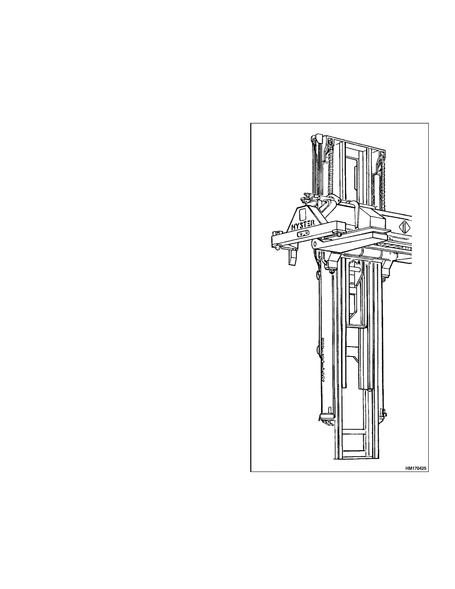
GENERAL
The vertical frames of a mast are called channel
weldments. See Figure 1. All of the masts have tele-
scopic weldments. The outer weldment is mounted
on support pins in the frame to let the mast tilt
forward and backward. The tilt cylinders connect
the outer weldment of the mast to the frame.
Hydraulic lift cylinders are installed vertically at
each side of the outer channel weldments. The lift
cylinders and lift chains raise and lower the inner
weldment and the carriage. The base of each lift
cylinder fits into a mount near the bottom of the
outer weldment. The top of each lift cylinder (cylin-
der rod) fits into a guide at the top of the inner
weldment. Operation of the lift cylinders extends
and retracts the inner weldment.
Two lift chains control the movement of the carriage.
The chains fasten to mounts near the top of the
outer weldment.
The chains go up and over the
chain sheaves and then connect to the carriage. The
chain sheaves are installed near the top of the inner
weldment. When the lift cylinders extend, the lift
chains transfer the force from the lift cylinders to
the carriage.
When the telescopic weldments and the carriage
lift a load, forces are put on the mast assembly. To
decrease the friction caused by these forces, load
rollers and side blocks are installed between the
moving parts. The load rollers and side blocks travel
along the channels within the weldments.
Figure 1. Mast
1

Safety Procedures When Working Near Mast
4000 SRM 1160
LIFTING
Oil from the main control valve enters the lift cylin-
ders at the lowering control valves. Because of the
heavy load on the mast, pressure in the base of the
lift cylinders is higher when there is a load. There
is no oil in the top of the lift cylinders, but there is a
drain line attached on top of the lift cylinders which
connects to the hydraulic tank.
LOWERING
During lowering, the oil from the lift cylinders flows
through the lowering control valves to the main con-
trol valve. See the section Diagrams 8000 SRM 1153
for the E117 lift trucks and Diagrams 8000 SRM
1236 for the F117 lift trucks. The lowering control
valves permit easy entry of hydraulic oil into the lift
cylinders, but give a restriction when the lift cylin-
ders are lowered. This restriction controls the speed
that a load can be lowered.
Safety Procedures When Working Near Mast
The following procedures must be used when inspect-
ing or working near the mast. Additional precautions
and procedures can be required when repairing or re-
moving the mast. See the correct Service Manual sec-
tion for the specific mast being repaired.
WARNING
Mast parts are heavy and can move. Distances
between parts are small.
Serious injury or
death can result if part of the body is hit by
parts of the mast or the carriage.
• Never put any part of the body into or under
the mast or carriage unless all parts are com-
pletely lowered or a safety chain is installed.
Also make sure that the power is OFF and the
key is removed. Put a DO NOT OPERATE tag
in the operator’s compartment.
• Be careful of the forks.
When the mast is
raised, the forks can be at a height to cause
an injury.
• Do NOT climb on the mast or lift truck at any
time. Use a ladder or personnel lift to work
on the mast.
• Do NOT use blocks to support the mast weld-
ments nor to restrain their movement.
• Mast repairs can require disassembly and re-
moval of parts and can require removal of the
mast or carriage. Follow the repair proce-
dures in the correct Service Manual for the
mast.
WHEN WORKING NEAR THE MAST ALWAYS:
1.
Lower the mast and carriage completely. Push
the lift/lower control lever forward and verify
there is no movement in the mast. Verify that all
parts of the mast that move are fully lowered.
OR
2.
If parts of the mast must be in raised position,
install a safety chain to restrain the moving parts
of the mast. Connect moving parts to a part that
does not move. Follow these procedures:
a. Put the mast in a vertical position.
b. Raise the mast to align the bottom cross-
member of the inner weldment with a cross-
member on the outer weldment.
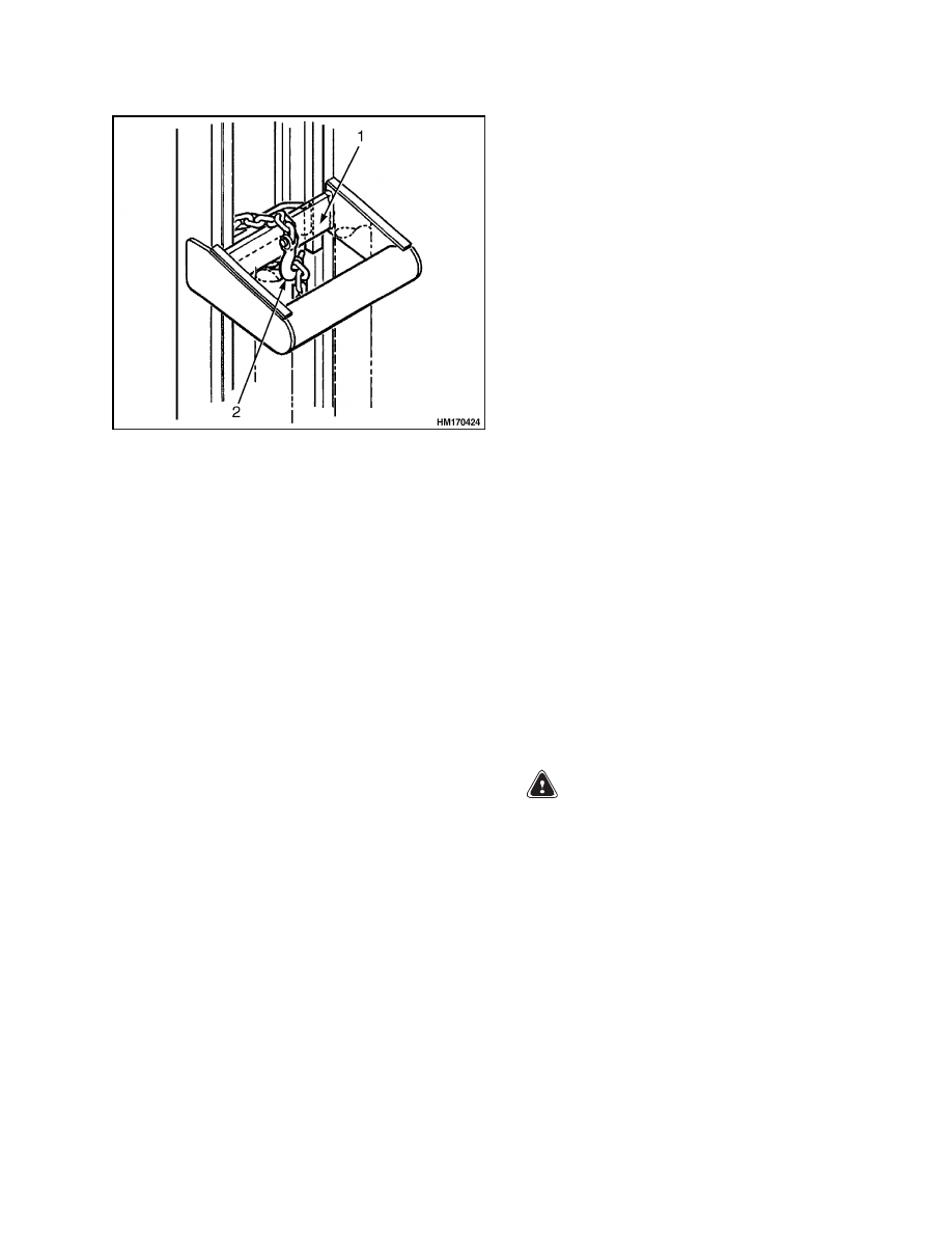
c.
Use a safety chain, which can hold a mini-
mum of 20,000 kg (44,093 lb), with a hook
to fasten the crossmembers together so that
the movable member cannot lower. Put the
hook on the back side of the mast. Verify the
hook is completely engaged with a link in the
chain. Verify the safety chain does not touch
lift chains or chain sheaves, tubes, hoses, fit-
tings, or other parts on the mast. See Fig-
ure 2.
d. Lower the mast until there is tension in the
safety chain. If running, stop the engine. Ap-
ply the parking brake. Install a DO NOT
REMOVE tag on the safety chain(s).
e.
Install another safety chain (1/2 inch mini-
mum) between the top or bottom crossmem-
ber of the carriage and a crossmember on the
outer weldment.
3.
Apply the parking brake. After lowering or re-
straining the mast, shut off the power and re-
move the key. Put a DO NOT OPERATE tag
in the operator’s compartment.
2
4000 SRM 1160
Carriage Repair
Figure 2. Mast Safety Chains
Legend for Figure 2
1.
OUTER WELDMENT
2.
HOOK
Carriage Repair
GENERAL
These procedures are for the following carriage types.
• Dedicated carriage. See Figure 3.
• Gantry carriage PPS (Power Pile Slope). See Fig-
ure 4.
• Gantry carriage MPS (Mechanical Pile Slope). See
REMOVE
1.
Remove the dedicated container attachment or
gantry container attachment.
See the section
Extendable Container Attachment (Elme),
812, 813, 815, and 818 Series 5000 SRM 723.
2.
Place lift truck on solid, level surface.
3.
Lower carriage completely.
4.
Apply parking brake.
5.
Shut down the engine.
6.
Put blocks on both sides (front and back) of the
tires to prevent movement of the lift truck.
7.
Connect a lifting device to the lifting eyes at each
side of the top crossmember of the carriage. Op-
erate the lifting device until the carriage just be-
gins to move.
NOTE: Tag all hoses, hydraulic lines, or wiring har-
nesses before removal.
8.
Disconnect any header hoses, hydraulic lines, or
wiring harness at the carriage.
9.
Put caps on open lines.
WARNING
When disconnecting the lift chains, maintain
control of the ends. Use wire to temporarily
connect the ends of the lift chains to the mast.
This procedure will prevent the lift chains
from falling and causing injury or damage.
10. Verify the lifting device is holding the carriage.
Disconnect lift chains at the carriage. Disconnect
chains by removing the pins from the chain an-
chors or remove the nuts from the chain anchors.
Connect the ends of the chain to the mast.
11. Start the engine.
3
Carriage Repair
4000 SRM 1160
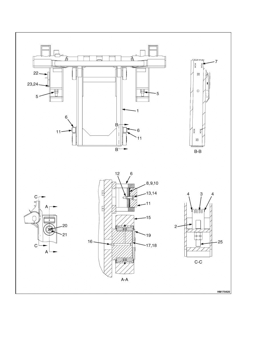
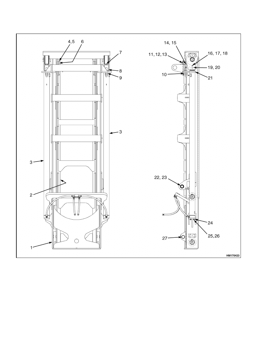
Figure 3. Dedicated Carriage Assembly
4

4000 SRM 1160
Carriage Repair
Legend for Figure 3
1.
DEDICATED CARRIAGE
2.
CHAIN ANCHOR
3.
PIN
4.
SNAP RING
5.
NUT
6.
BEARING BRACKET
7.
CAPSCREW
8.
SHIM
9.
SHIM
10. SHIM
11. BEARING BLOCK
12. NUT
13. WASHER
14. CAPSCREW
15. ROLLER ASSEMBLY
16. LUBE FITTING
17. SHIM
18. SHIM
19. CAP
20. PIPE FITTING
21. CAPSCREW
22. BRACKET
23. CAPSCREW
24. NUT
25. LUBRICANT
CAUTION
Raising the inner weldment will cause the
chain sheaves to raise the lift chains. Verify
the lift chains are connected loosely enough so
the inner weldment can raise with the chains
still connected.
12. Operate the lift cylinders to raise the inner weld-
ment. Verify the lifting mechanism is directly
over the carriage.
Raise inner weldment just
past the top load rollers of the carriage.
13. Shut down the engine.
14. Remove the carriage from the lift truck. Lower
the carriage to the floor so that the load rollers
are up.
DISASSEMBLE
1.
Remove the load rollers as follows:
a. Remove the four capscrews that hold re-
tainer to the stub shafts. Remove retainer.
b. Remove the shims.
c.
Make identification marks on the shims so
that they will be installed in the same order.
d. Remove the load roller from the stub shaft.
Remove the shields and bearings from the
load roller.
2.
Remove side blocks as follows:
NOTE: If necessary, it is possible to equip the carriage
with side rollers as an option.
a. Remove the capscrews that hold the side
block to the carriage.
b. Remove the capscrew that holds the wear
plate.
c.
Remove the shims.
3.
Remove the chain anchor as follows:
a. Remove nuts that hold the chain anchor to
the carriage.
CLEAN AND INSPECT
Use steam or solvent to clean the parts of the car-
riage.
CAUTION
Do not use steam to clean the side blocks, side
rollers, and load rollers. Steam will cause cor-
rosion and damage to the parts.
Inspect the carriage weldments, side blocks, and load
rollers for wear or damage. Inspect the welds for
cracks.
5
Carriage Repair
4000 SRM 1160
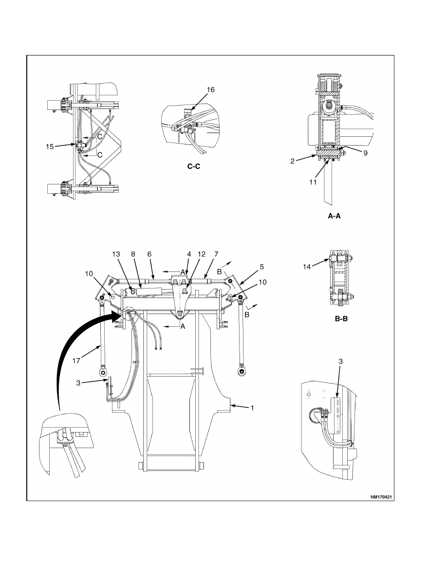
Figure 4. Gantry Carriage PPS (Power Pile Slope)
6

4000 SRM 1160
Carriage Repair
Legend for Figure 4
1.
GANTRY CARRIAGE
2.
PIN WELDMENT
3.
BRACKET
4.
PIVOT ARM
5.
PIVOT ARM
6.
TELESCOPIC ROD ASSEMBLY
7.
ROD
8.
HYDRAULIC CYLINDER, POWER PILE SLOPE
9.
BUSHING
10. PIN WELDMENT
11. LUBE FITTING
12. PIN WELDMENT
13. PIN
14. PIN WELDMENT
15. MANIFOLD ASSEMBLY, POWER PILE SLOPE
16. SOLENOID VALVE
17. HANGER SET, FIXED LENGTH
ASSEMBLE
1.
Install the load rollers as follows:
a. Install the snap rings in the center of the load
roller. Install the bearing cups.
b. Lubricate the bearing cones and install them
in the load roller. Install the shields on the
bearings.
c.
Lubricate the stub shaft and install the load
roller on the shaft.
d. Install the retainer (without shims) and cap-
screws on the stub shaft. Tighten the cap-
screws to 47 N•m (35 lbf ft) while rotating
the load roller.
e.
Loosen the capscrews that hold the retainer.
f.
Tighten the capscrews evenly again while
checking the load roller for side movement.
Tighten the capscrews until there is no side
movement.
g. Measure the clearance between the stub
shaft and the retainer. Remove the retainer.
Install shims equal to the measurement.
h. Install the retainer, shims, and capscrews.
Tighten the capscrews to 115 N•m (85 lbf ft).
2.
Install the side blocks as follows:
a. Install side block to the carriage with four
capscrews.
b. Tighten the capscrews to 130 N•m (96 lbf ft).
c.
Install wear plates.
d. Use a pry bar to move the inner weldment
from side to side to measure the amount of
movement. Maximum clearance at the point
of the tightest fit is 0.5 to 1.5 mm (0.020
to 0.060 in.). Adjust the wear plates as de-
scribed in Carriage Side Blocks, Adjust in
this section.
3.
Install the chain anchor as follows:
a. Install the nuts that hold the chain anchor to
the carriage.
INSTALL
1.
Connect a lifting device at each side of the top
crossmember of the carriage.
2.
Start the engine.
3.
Operate the lift cylinders to raise the inner weld-
ment of the mast. Raise the inner weldment just
past the top load rollers of the carriage.
4.
Shut down the engine.
WARNING
When disconnecting the lift chains, maintain
control of the ends. Use wire to temporarily
connect the ends of the lift chains to the mast.
This procedure will prevent the lift chains
from falling and causing injury or damage.
5.
Operate the lifting device and move the carriage
into position under the inner weldment.
6.
Start the engine.
7.
Lower the inner weldment completely to engage
the rollers of the carriage.
8.
Shut down the engine.
9.
Raise the carriage and connect the lift chains at
the carriage. Remove the lifting device. Adjust
the lift chains as described in Lift Chains Adjust-
ment in this section.
10. Connect header hoses, hydraulic lines, and
wiring harness at the carriage.
7
Carriage Repair
4000 SRM 1160
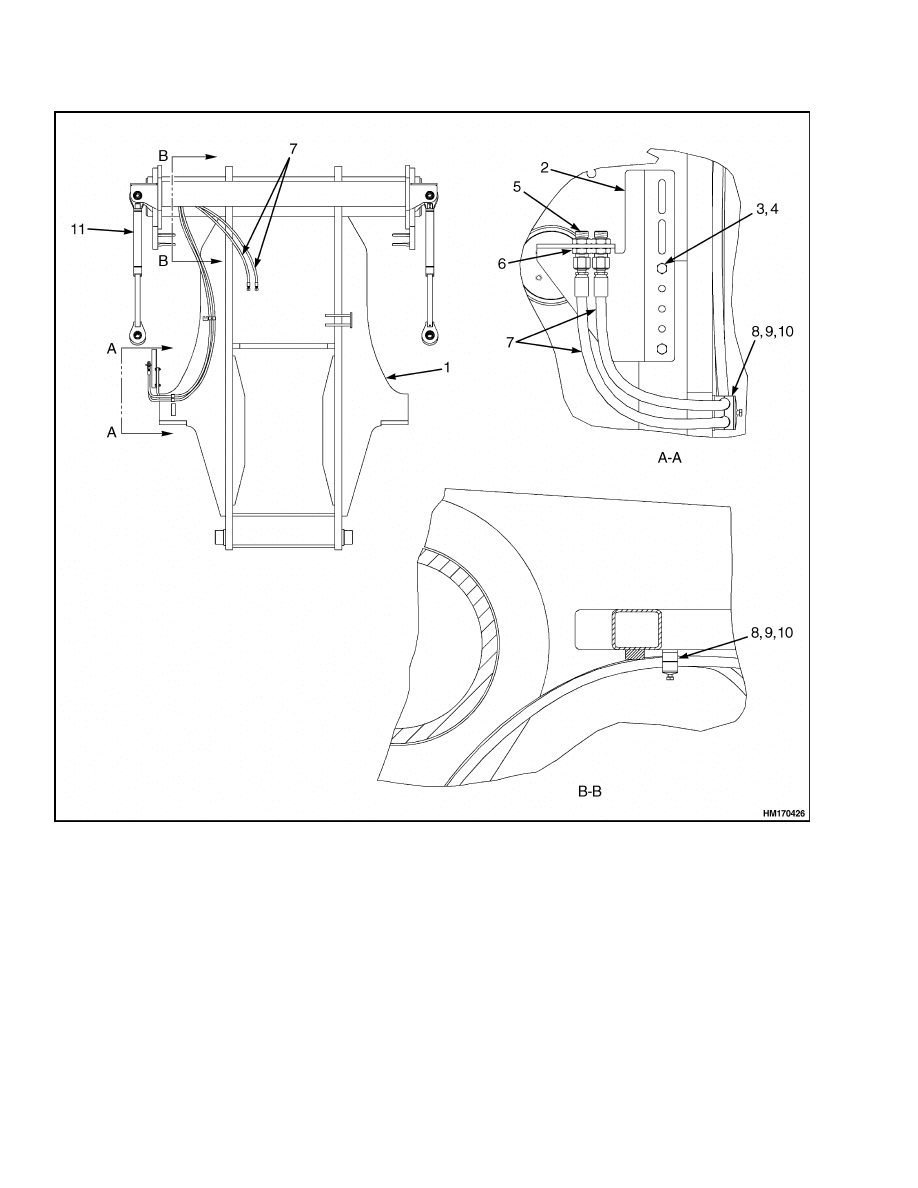
1.
GANTRY CARRIAGE
2.
BRACKET
3.
CAPSCREW
4.
NUT
5.
FITTING
6.
NUT
7.
HOSE ASSEMBLY
8.
CLAMP
9.
PLATE
10. CAPSCREW
11. HANGER SET, FIXED LENGTH
Figure 5. Gantry Carriage MPS (Mechanical Pile Slope)
8
4000 SRM 1160
Mast Repair
WARNING
Do not try to locate hydraulic leaks by putting
hands on pressurized hydraulic components.
Hydraulic oil can be injected into the body by
pressure and cause personal injury.
11. Start the engine and operate the hydraulic sys-
tem.
Check that all functions of the carriage
work correctly.
12. Check for leaks.
13. Remove the blocks from the front and back of the
tires.
CARRIAGE SIDE BLOCKS
Adjust
1.
Adjust wear plates so maximum clearance at the
point of tightest fit is 0.5 to 1.5 mm (0.020 to
0.060 in.).
NOTE: If more than five shims are required, replace
the bearing block.
2.
Insert shims between wear plate and bearing
bracket weldment as necessary.
Mast Repair
REMOVE
1.
Remove the carriage as described in the section
Carriage Repair. Lower the mast completely.
2.
Disconnect the two hydraulic lines at the base of
each lift cylinder (from the junction block). Put
caps on open lines.
WARNING
When removing the mast assembly, verify the
lifting devices have the correct capacity.
3.
Connect the lifting device to the lifting eyes on
the outer weldment of the mast. Search for the
best center of gravity in which the mast mount
assembly has minor tension. Location of the lift-
ing device will be away from the lift truck.
4.
Disconnect the tilt cylinders from the mast as fol-
lows:
a. Attach a lifting device and chains for support
of the tilt cylinders.
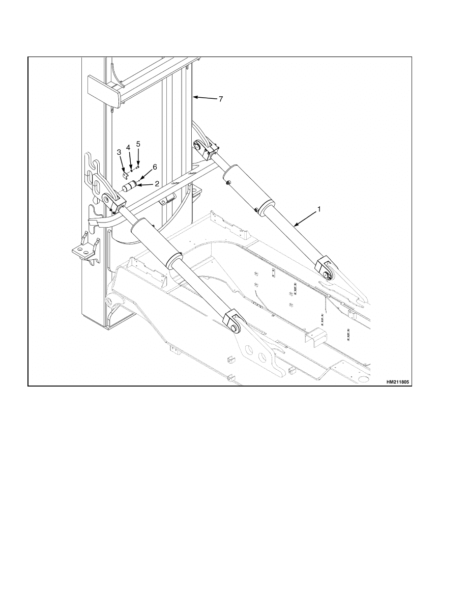
b. Remove the capscrew and retaining pin from
each tilt cylinder anchor pin from the mount
on the mast. Use a pulley to pull out the
anchor pins. Lower the tilt cylinders to the
frame. Put blocks under the cylinders to se-
cure the cylinders. See Figure 6.
WARNING
Do not use your finger to push the anchor pins.
The tilt cylinder can drop and cause injury.
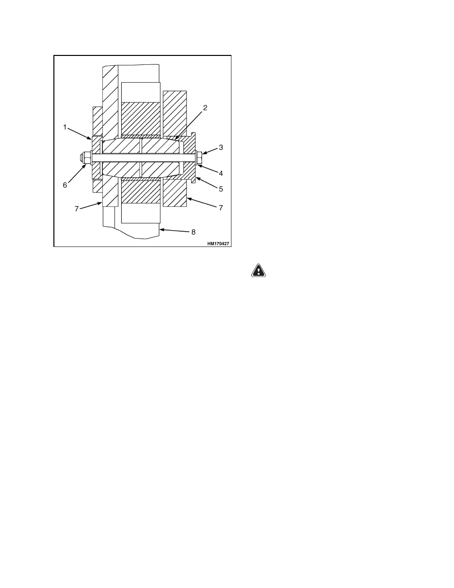
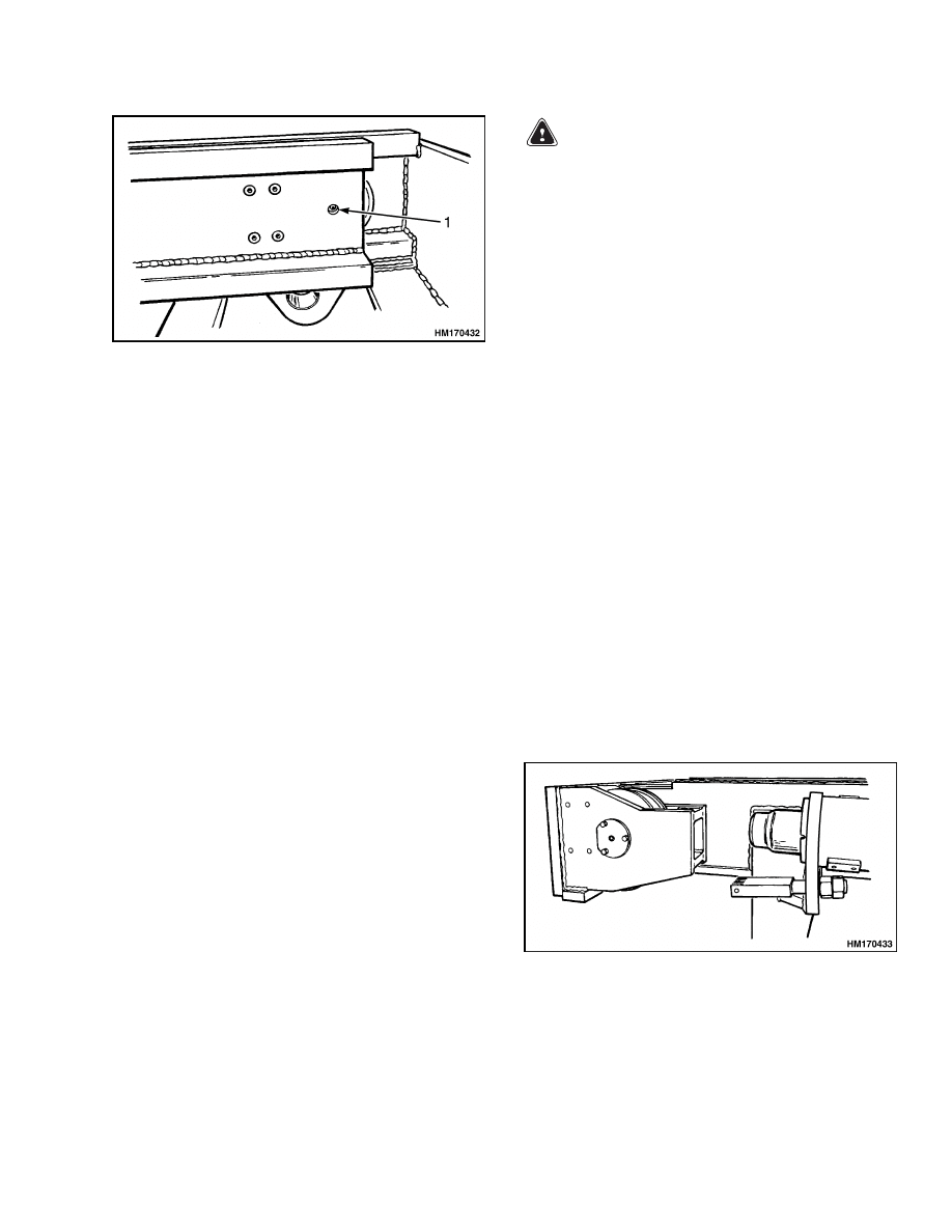
5.
Remove nut, capscrew, and outer cap from both
mast mounts. See Figure 7.
6.
Remove the inner cap. Use 1/2-in. UNC cap-
screws in the threaded holes to push the inner
cap out of the bore of the mast hanger.
7.
Remove the support pins. Verify the lifting de-
vice controls the mast. Lift the mast away from
the lift truck. Lower the mast on blocks so the
mast mounts on the channel weldments are up.
Put blocks under the outer weldment so that the
inner weldment can move.
9
Mast Repair
4000 SRM 1160
1.
TILT CYLINDER
2.
ANCHOR PIN
3.
RETAINER
4.
WASHER
5.
CAPSCREW
6.
SCREW
7.
MAST
Figure 6. Tilt Cylinder
10
4000 SRM 1160
Mast Repair
1.
CAP
2.
PIN
3.
CAPSCREW
4.
WASHER
5.
CAP
6.
LOCK NUT
7.
FRAME
8.
MAST
Figure 7. Mast Mount to Frame
DISASSEMBLE
1.
Disconnect the lift chains from the outer weld-
ment. Remove the lift chains.
2.
Remove the lift cylinders as follows (see Fig-
ure 8):
a. Connect a lifting device to the lift cylinder.
Raise the cylinder just enough to put tension
on the lifting device.
b. Remove the capscrew from the top of the lift
cylinder. Use a pry bar to extend the inner
weldment approximately 150 mm (6 in.).
c.
Remove the capscrews from the bottom of the
lift cylinder. Remove the lift cylinder from
the mast. Disassemble the lift cylinder as
described in Lift Cylinders Repair.
3.
Remove and disassemble the chain sheaves as
follows (see Figure 9):
a. Connect a lifting device to the chain sheave.
Operate the lifting device just enough to sup-
port the chain sheave.
b. Remove both covers for the shaft of the chain
sheave. Remove the shims.
c.
Use a drive punch to remove the shaft. Re-
move the chain sheave and spacer from the
mast.
d. Remove the bearings and seals from the
chain sheave.
4.
Remove the side blocks at the top of the outer
weldment. Keep the shims with each side block.
WARNING
Verify the lifting devices have the correct ca-
pacity.
5.
Connect a lifting device to the top crossmember
of the inner weldment. Pull the inner weldment
halfway out of the outer weldment. Move the lift-
ing device to the center of the inner weldment.
Remove the inner weldment from the outer weld-
ment.
6.
Remove the load rollers and side blocks as neces-
sary.
11
Mast Repair
4000 SRM 1160
1.
OUTER MAST WELDMENT
2.
INNER MAST WELDMENT
3.
LIFT CYLINDER
4.
LOCKWASHER
5.
CAPSCREW
6.
PLATE
7.
CHAIN
8.
CHAIN ANCHOR
9.
NUT
10. WEAR SHOE
11. SHIM
12. SHIM
13. SHIM
14. SNAP RING
15. SNAP RING
16. NUT
17. WASHER
18. STUD
19. SHIM
20. SHIM
21. TUBE
22. BEARING
23. SNAP RING
24. PLATE
25. LOCKWASHER
26. CAPSCREW
27. BUSHING
Figure 8. Mast Assembly
12
4000 SRM 1160
Mast Repair
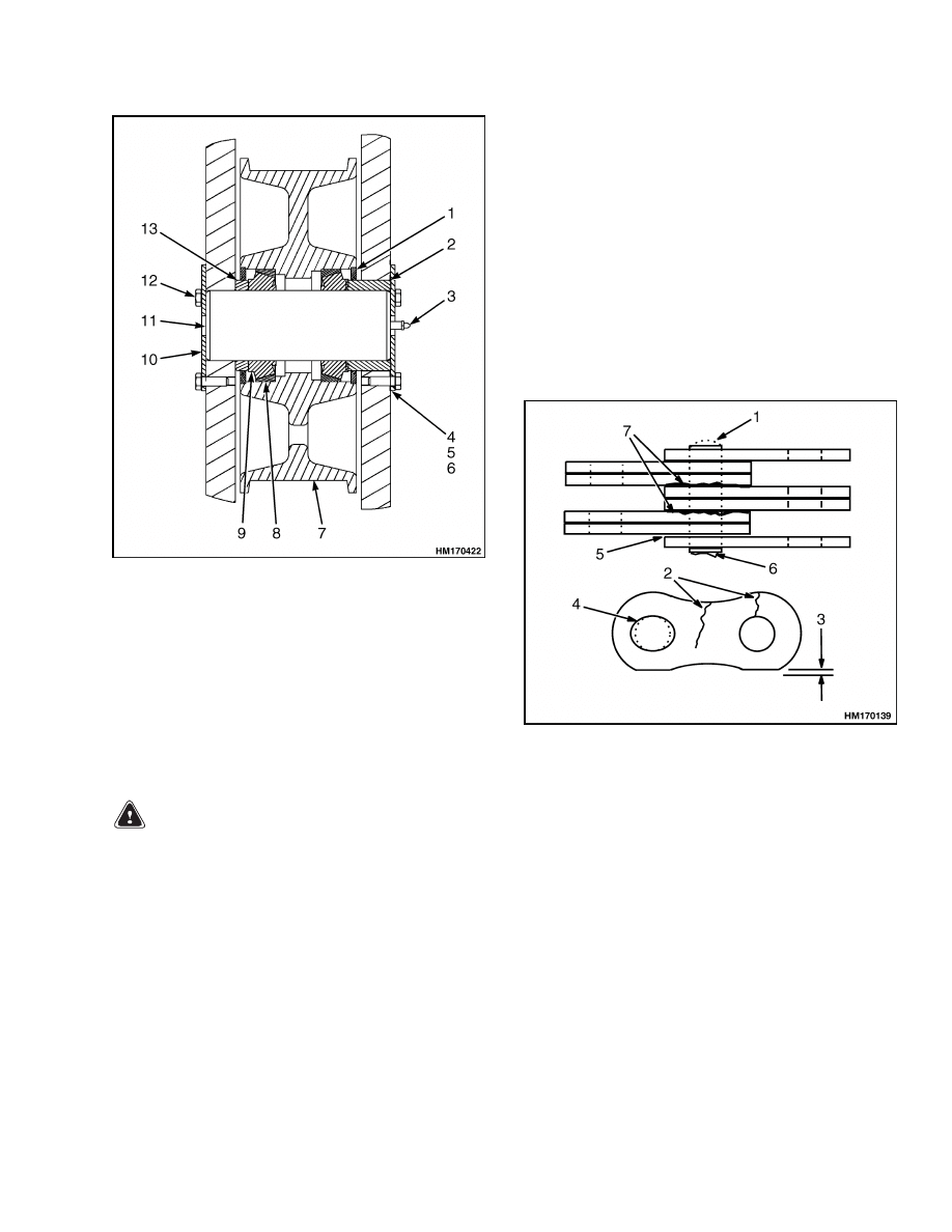
1.
OIL SEAL
2.
SPACER
3.
LUBE FITTING
4.
SHIM
5.
SHIM
6.
SHIM
7.
SHEAVE
8.
ROLLER BEARING
CUP
9.
ROLLER BEARING
CONE
10. COVER
11. CAPSCREW
12. CAPSCREW
13. SPACER
Figure 9. Chain Sheave
CLEAN AND INSPECT
WARNING
DO NOT weld on any part of the mast assembly
including the weldments, forks, or carriage.
Get information from your Hyster lift truck
dealer before welding on the mast.
1.
Inspect the sheaves and load rollers. Replace any
parts that are worn or damaged. DO NOT use
steam to clean the lift chains, sheaves, or load
rollers.
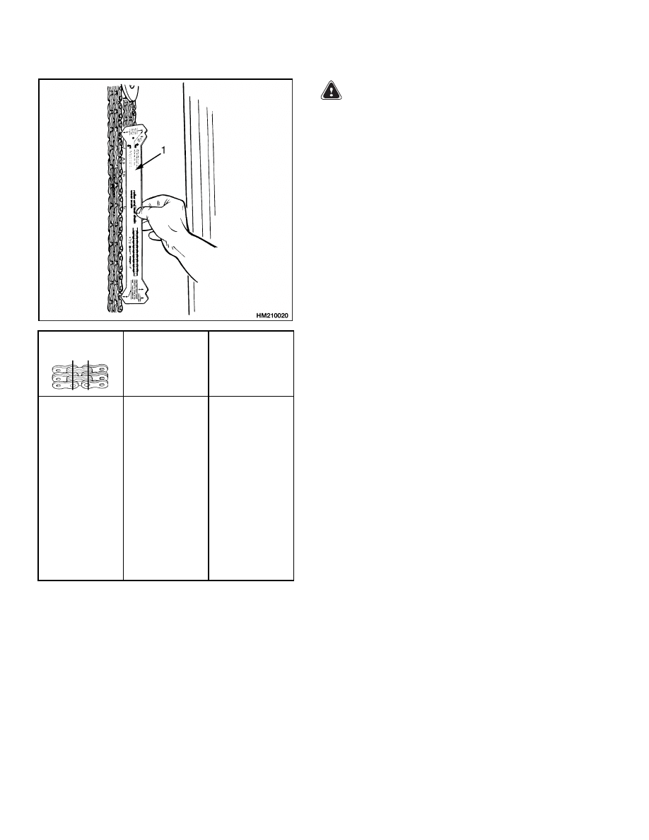
2.
Clean the lift chains with solvent. Inspect the lift
chains for wear or damage. See Figure 10. A lift
chain becomes longer when it is worn. If a chain
is 3% longer than a new lift chain, the lift chain
must be replaced. Use a chain scale to measure
the chains. If a chain scale is not available, check
the lift chains with the measurements given in
Figure 11. Lubricate the chains with SAE 30
engine oil. The best procedure is to remove the
chains from the lift truck and soak them in oil.
1.
WORN PIN
2.
CRACKS
3.
EDGE WEAR
(MAXIMUM 5% OF
NEW)
4.
HOLE WEAR
5.
LOOSE LEAVES
6.
DAMAGED PIN
7.
CORROSION
Figure 10. Lift Chains Check
13
Mast Repair
4000 SRM 1160
Pitch
Total Length
of 20 Links
(Pitch) of New
Chain
Wear Limit
The Maximum
Length of 20
Links
12.7 mm
(0.50 in.)
15.9 mm
(0.626 in.)
19.1 mm
(0.75 in.)
25.4 mm
(1.00 in.)
31.8 mm
(1.25 in.)
44.5 mm
(1.75 in.)
50.8 mm
(2.00 in.)
254.0 mm
(10.0 in.)
317.5 mm
(12.5 in.)
381.0 mm
(15.0 in.)
508.0 mm
(20.0 in.)
635.0 mm
(25.0 in.)
889.0 mm
(35.0 in.)
1016.0 mm
(40.0 in.)
261.6 mm
(10.3 in.)
327.0 mm
(12.87 in.)
392.4 mm
(15.45 in.)
523.25 mm
(20.6 in.)
654.1 mm
(25.75 in.)
915.7 mm
(36.05 in.)
1046.5 mm
(41.2 in.)
NOTE: INSTRUCTIONS FOR MEASURING CHAIN
WEAR ARE SHOWN ON THE CHAIN WEAR SCALE.
1.
CHAIN WEAR SCALE
Figure 11. Lift Chains Check
WARNING
Never replace just the worn section of a chain.
Replace the complete chain. Never replace just
one chain of a chain pair. Replace both chains.
3.
Inspect the chain anchors and pins. Replace any
parts that are worn or damaged.
4.
Clean the mast weldments with steam or solvent.
5.
Inspect the sliding and rolling surfaces for dam-
age. Inspect all welds for cracks.
ASSEMBLE
1.
Install the load rollers on the inner weldment as
follows (see Figure 17):
a. Lubricate the bearings with oil. Install the
bearings and shields in the load roller.
b. Install the load roller on the stub shaft.
Install the retainer plate without shims.
Tighten the capscrews to 47 N•m (35 lbf ft)
while rotating the load roller.
c.
Loosen the capscrews for the retainer.
d. Tighten the capscrews for the retainer until
there is zero clearance in the bearings. Mea-
sure the clearance between the stub shaft
and the retainer.
Measure the clearance
through the hole in the retainer.
e.
Remove the retainer. Install shims equal to
the measurement made in Step d.
f.
Install the retainer plate. Tighten the cap-
screws to 115 N•m (85 lbf ft). Lubricate the
load rollers with multipurpose grease at the
grease fittings.
2.
Install the side block at the bottom of the inner
weldment as follows:
a. Install the bushings in the side block. Install
new O-rings on the shaft. Install the side
block in the mount.
b. Install the side block, spacer, and shims on
the inner weldment. Verify the grease fitting
in the side block can be reached through the
hole in the spacer and mast weldment. See
Figure 12.
14
4000 SRM 1160
Mast Repair
1.
HOLE WITH GREASE FITTING
Figure 12. Inner Weldment
c.
Adjust the side blocks as described in Mast
Side Blocks Adjustment in this section.
3.
Install the capscrew and washers for the lift
cylinders at the top of the inner weldment. The
capscrew cannot be installed after the chain
sheave is installed.
4.
Install the chain sheaves as follows (see Fig-
ure 9):
a. Lubricate the bearings, then install the bear-
ings in the chain sheave. Install the oil seals
in the chain sheave.
b. Connect a lifting device to the chain sheave.
Install the short spacer in the chain sheave.
c.
Install the chain sheave in the inner weld-
ment. The short spacer fits toward the out-
side of the mast. Install the long spacer in the
inner weldment. Install the shaft with the
grease fitting toward the inside of the mast.
d. Install the retainer on the outside of the in-
ner weldment. Install the retainer on the in-
side of the inner weldment. (Do not install
the shims at this time.)
Tighten the cap-
screws for the retainer until rotation of the
chain sheave becomes difficult. Measure the
clearance between the retainer and the inner
weldment. Install enough shims under the
retainer to give zero clearance in the bear-
ings.
WARNING
Verify the lifting devices have the correct ca-
pacity.
5.
Connect a lifting device to the center of the inner
weldment.
Verify the inner weldment can be
raised and remain horizontal. Install the inner
weldment into the outer weldment. When the
inner weldment is at least two-thirds installed,
install the side block at the top of the outer
weldment. Install the side block as described in
Step 2.
Push the inner weldment until it extends approx-
imately 150 mm (6 in.) out of the outer weldment.
6.
Install the lift cylinders as follows:
a. Connect a lifting device to the lift cylinder.
b. Install the lift cylinder in position on the
outer weldment.
Install the capscrews,
washers, and keeper plates at the bottom
mount for the lift cylinder.
Install the spacer on the capscrew that fits
at the top of the lift cylinder. Push the inner
weldment until it engages with the rod of the
lift cylinder. See Figure 13. Tighten the cap-
screws at the top of the lift cylinder.
7.
Install the chain anchors in the outer weldment.
Install the lift chains to the chain anchors. Use
wire to connect the other end of the lift chains
close to the bottom of the outer weldment.
Figure 13. Lift Cylinder Installation
15
Lift Cylinders Repair
4000 SRM 1160
INSTALL
WARNING
Verify the lifting devices have the correct ca-
pacity.
1.
Connect a lifting device to the top crossmembers
of the inner and outer weldments.
2.
Raise the mast assembly and verify it has stabil-
ity. Move the mast to the mounts on the frame of
the lift truck. Align the holes in the mounts with
the holes in the mast.
NOTE: Verify the support pins are completely free of
grease before installation.
3.
Operate the lifting device to move the mast so
the tilt cylinders can be connected. Lubricate and
install the pins for the tilt cylinders. Install the
anchor pins for the tilt cylinder pins.
4.
Disconnect the lifting device from the mast. Con-
nect the hydraulic lines to lift cylinders.
5.
Install the carriage as described in Carriage Re-
pair.
Lift Cylinders Repair
REMOVE
Remove the lift cylinders as described in Mast Re-
pair, Disassemble.
DISASSEMBLE
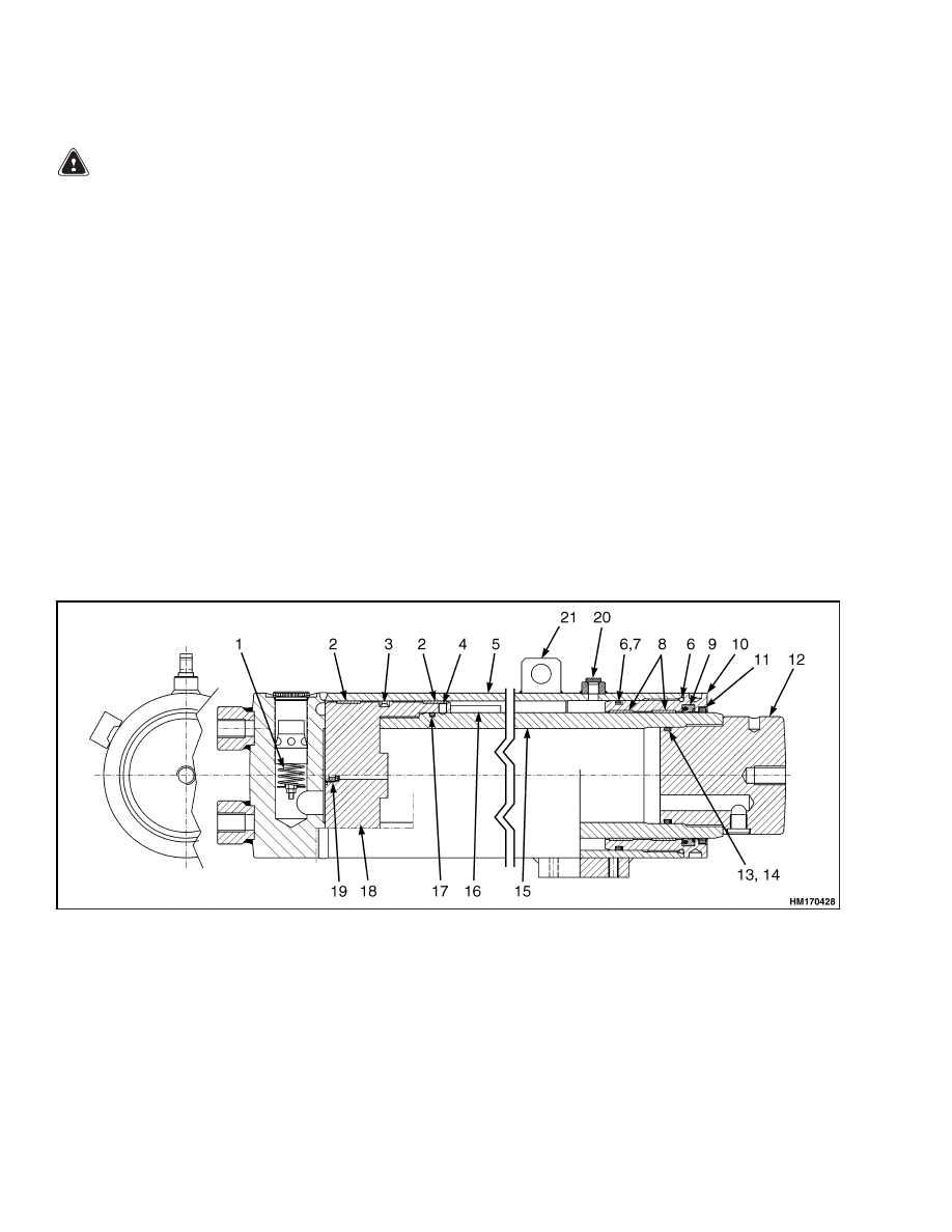
1.
Remove the retainer from the cylinder shell. See
Figure 14.
2.
Install a lifting eye on the end of the cylinder rod.
Pull the rod from the shell.
3.
Remove the seals and O-rings from the parts of
the cylinder.
4.
Remove the lowering control valve and fittings
from the base of the cylinder.
1.
VALVE
2.
WEAR BAND
3.
PISTON SEAL
4.
SCREW (USE LOCTITE
®
242)
5.
CYLINDER SHELL
6.
O-RING
7.
BACKUP RING
8.
WEAR BAND
9.
ROD SEAL
10. BEARING
11. WIPER
12. ROD END (USE LOCTITE
®
270)
13. O-RING
14. BACKUP RING
15. PISTON ROD
16. SPACER
17. O-RING
18. PISTON (USE LOCTITE
®
242)
19. VALVE/PLUG
20. DRAIN PLUG
21. LIFTING EYE
Figure 14. Lift Cylinder
16
4000 SRM 1160
Header Hoses Replacement
CLEAN AND INSPECT
Clean all the parts of the lift cylinder in solvent. In-
spect the bore and rod for scratches or grooves.
ASSEMBLE
1.
Install the lowering control valve, check valve,
and fittings in the base of the cylinder. See Fig-
ure 14.
NOTE: The seal can be installed on the piston with
the use of a cone. Make a cone (wood) that is approx-
imately 250 mm (10 in.) long. Make the small end of
the cone approximately 6 mm (0.25 in.) smaller than
the inside diameter of the seal. Make the large end of
the cone approximately 6 mm (0.25 in.) larger than
the piston. Fasten the cone to the piston by using the
hole in the bottom of the piston. Put the seal on the
cone. Use a wood or plastic drift to push the seal onto
the cone and piston.
2.
Install the seal on the piston as follows:
a. Install part of the seal in the groove of the
piston. Have a helper hold the seal in the
groove.
b. Use two bars [at least 460 mm (18 in.) long
and approximately 10 mm (0.38 in.) in diam-
eter] that have a tapered end. Verify the bars
are smooth so the seal is not damaged.
c.
With the tapered end of the bars toward the
piston, use the bars to pull the seal into the
groove. It will take several minutes for the
seal to increase in size to fit over the piston.
After installation, it will take several min-
utes for the seal to decrease to its original
size.
d. Install the backup rings on both sides of the
piston seal.
e.
Install the wear ring on the piston.
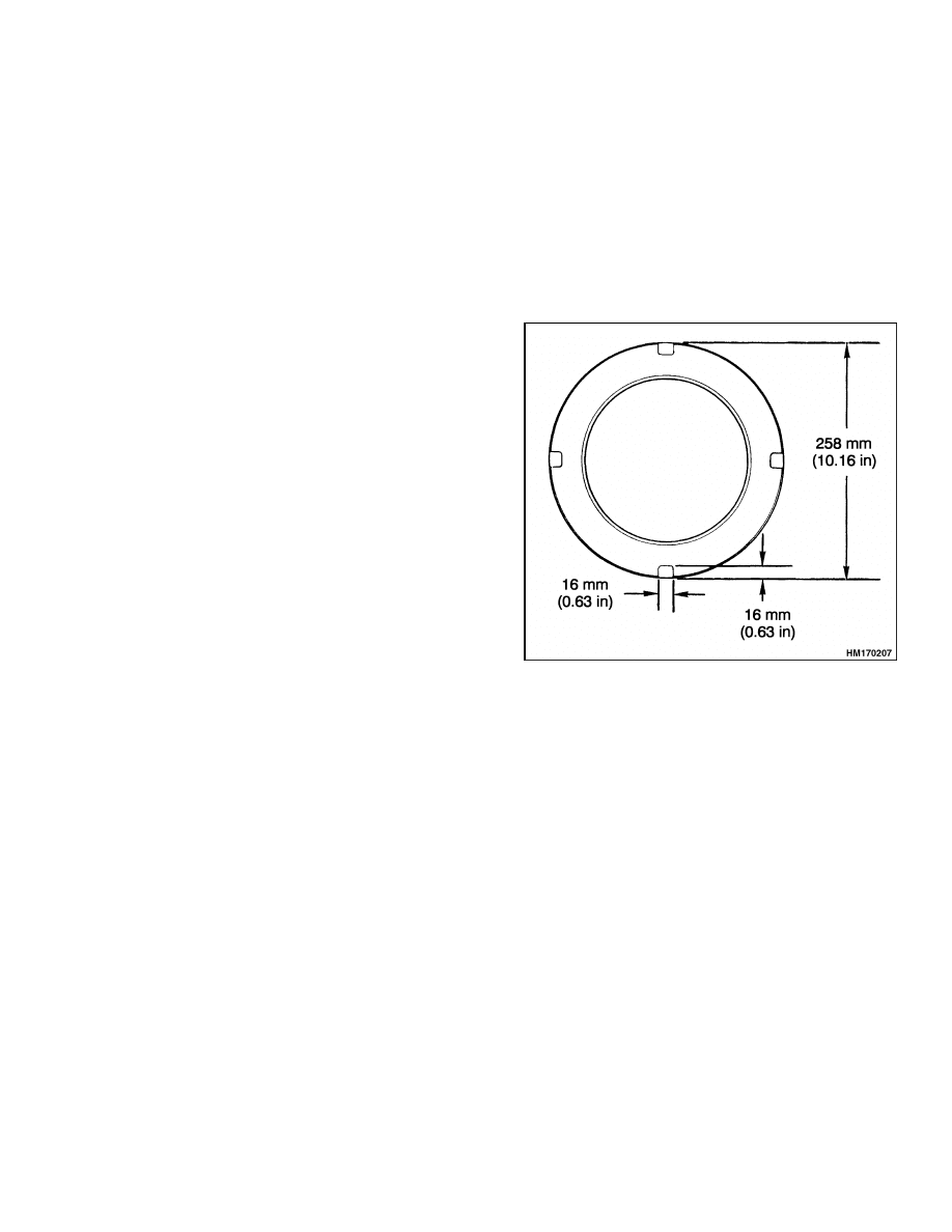
3.
Install the O-ring, backup ring, nylon plug, rod
seal, and rod wiper in the retainer. Install the
retainer. It is necessary to make a special tool
to tighten the retainer. See Figure 15 for the
dimensions of the retainer. Tighten the retainer
to 1065 N•m (785 lbf ft).
Figure 15. Retainer Dimensions
INSTALL
Install the lift cylinder as described in Mast Repair,
Assemble, Step 6.
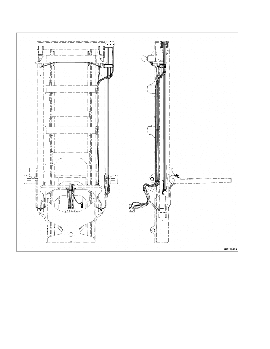
Header Hoses Replacement
The header hoses are the hydraulic lines that con-
nect the attachment cylinders to the hydraulic
system of the lift truck.
The header hoses move
on hose sheaves that are installed at the top of the
outer weldment.
When removing or installing the header hoses, verify
they are connected to the correct fittings as shown
in Figure 16. To install the hoses, use the following
procedure:
1.
Connect the hoses to the fittings on the lift truck.
2.
Use clamps and fasten the hoses to the mast. Do
not tighten the clamps for the hoses at the top of
the lift cylinder.
3.
Put the hoses over the sheaves. Put tension on
the hoses by pulling on them with 16 kg (35 lb)
of force and then tighten the clamps at the top of
the lift cylinder.
4.
Install the hose with the wiring harness as de-
scribed in Step 2 and Step 3 above. After tight-
ening the clamps for the hose, verify the wiring
harness moves freely inside the hose.
17
Carriage Side Blocks Adjustment
4000 SRM 1160
Figure 16. Header Hoses Arrangement
Carriage Side Blocks Adjustment
1.
Adjust the wear plates so the maximum clear-
ance at the point of the tightest fit is 0.5 to
1.5 mm (0.020 to 0.060 in.).
NOTE: If more than five shims are required, replace
the bearing block.
2.
Insert shims between wear plate and bearing
bracket weldment as necessary.
18
4000 SRM 1160
Mast Load Rollers Adjustment
Mast Side Blocks Adjustment
1.
Adjust the wear plates so maximum clearance at
the point of tightest fit is 0.5 to 1.5 mm (0.020 to
0.059 in.).
NOTE: If more than five shims are required, replace
the side block.
2.
Insert shims between wear plate and bearing
bracket weldment as necessary.
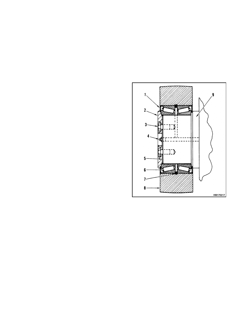
Mast Load Rollers Adjustment
1.
Remove the four capscrews and the retainer
plate. See Figure 17. Remove the shims between
the retainer plate and the bearing. Replace the
retainer plate and the capscrews. Tighten the
capscrews to 47 N•m (35 lbf ft) while rotating
the load roller.
2.
Loosen the capscrews that hold the retainer plate
to the stub shaft.
3.
Tighten the capscrews evenly again while check-
ing the load roller for side movement. Tighten
the capscrews until the movement just stops.
Verify the load roller still rotates.
Measure
the clearance between the stub shaft and the
retainer plate.
Gain access to the clearance
through the hole in the center of the retainer
plate.
4.
Remove the retainer plate. Install shims of equal
thickness to the measurement taken in Step 3.
5.
Install the retainer plate. Tighten the capscrews
to 115 N•m (85 lbf ft). Lubricate the load rollers
with multipurpose grease at the grease fittings.
1.
BEARING SHIELD
2.
RETAINER PLATE
3.
CAPSCREW
4.
GREASE FITTING
5.
SHIMS
6.
BEARINGS
7.
SNAP RINGS
8.
LOAD ROLLER
9.
STUB SHAFT
Figure 17. Load Roller
19
Lift and Tilt Cylinders Leak Check
4000 SRM 1160
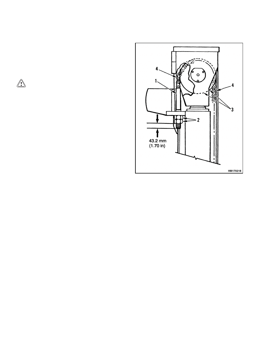
Lift Chains Adjustment
1.
Adjust the nuts on the chain anchors to the di-
mension shown in Figure 18.
2.
Install the nuts fully on the threaded areas of
the chain anchors, then loosen the nuts until the
tension on both lift chains is the same.
CAUTION
Verify the carriage (top side rollers) does not
touch the inside top of the inner weldment.
3.
Extend the mast fully. Verify the chain anchors
do not touch the chain sheave. There must be a
minimum clearance of 6.4 mm (0.25 in.) between
the chain anchor and the chain sheaves.
1.
CHAIN ANCHOR
2.
NUT
3.
CHAIN SHEAVE
4.
LIFT CHAIN
Figure 18. Lift Chains Adjustment
Lift and Tilt Cylinders Leak Check
Check the lift and tilt cylinders for leakage as de-
scribed in the section Periodic Maintenance 8000
SRM 1154 for E117 lift trucks and Periodic Main-
tenance 8000 SRM 1237 for F117 lift trucks.
20

4000 SRM 1160
Troubleshooting
Troubleshooting
PROBLEM
POSSIBLE CAUSE
PROCEDURE OR ACTION
No movement of the lift
cylinders.
Lift control linkage is disconnected.
Connect lift control linkage.
No oil or not enough oil to the lift
cylinders.
Fill tank. Check for leaks.
Relief valve is set too low or a check
valve is bad.
Adjust or install new relief valve or
check valve.
Pilot line is damaged.
Replace pilot line.
Pilot pressure is not correct.
Adjust pilot pressure.
Spool in main control valve does not
operate correctly.
Repair or replace spool in main con-
trol valve.
Slow action of the lift cylin-
ders.
No oil or not enough oil to the lift
cylinders.
Fill tank. Check for leaks.
Lift cylinder seals are damaged.
Replace lift cylinder seals.
Lift cylinders have internal or exter-
nal leaks.
Repair leaks. Install new parts.
The relief pressure at the main con-
trol valve is not correct.
Adjust relief pressure.
Rough movement of the mast
assembly.
Lift cylinders have internal or exter-
nal leaks.
Repair leaks.
Relief pressure at main control valve
is not correct.
Adjust relief pressure.
Air in the hydraulic system.
Bleed system. Check for loose con-
nections or break in lines.
Damaged cylinder rod(s), bent lift
cylinders.
Replace damaged rod(s) or cylinders.
Mast assembly is damaged or not in
alignment.
Repair or align mast assembly.
21

Troubleshooting
4000 SRM 1160
PROBLEM
POSSIBLE CAUSE
PROCEDURE OR ACTION
The tilt cylinder movement
is slow or is not smooth.
Lowering control valve(s) do not op-
erate correctly.
Repair or replace lowering control
valve(s).
No oil or not enough oil to the tilt
cylinders.
Fill tank. Check for leaks.
The seals in the tilt cylinders are
damaged.
Replace seals.
The relief valve is not adjusted cor-
rectly.
Adjust relief valve.
The tilt cylinders permit the
mast to move when the lever
is in the Neutral position.
There is air in the hydraulic system.
Bleed system.
Check for loose con-
nections or break in lines.
The tilt cylinders have internal dam-
age.
Repair or replace tilt cylinders.
There is leakage in the hydraulic
lines of the tilt system.
Repair or replace hydraulic lines.
The seals in the tilt cylinders are
damaged.
Replace seals.
The main control valve is damaged.
Repair or replace main control valve.
The tilt cylinders tilt the
mast forward or backward
too slowly.
The main control valve is damaged.
Repair or replace main control valve.
There is a leak in the hydraulic sys-
tem.
Repair leaks in the hydraulic system.
The relief pressure at the main con-
trol valve is not correct.
Adjust relief pressure at the main
control valve.
Pilot pressure is not correct.
Adjust pilot pressure.
22


TECHNICAL PUBLICATIONS
4000 SRM 1160
8/05 (8/04)(7/04) Printed in United Kingdom
Document Outline
- toc
- Mast
- Safety Precautions Maintenance and Repair
- General
- Description and Operation
- Safety Procedures When Working Near Mast
- Carriage Repair
- Mast Repair
- Lift Cylinders Repair
- Header Hoses Replacement
- Carriage Side Blocks Adjustment
- Mast Side Blocks Adjustment
- Mast Load Rollers Adjustment
- Lift Chains Adjustment
- Lift and Tilt Cylinders Leak Check
- Troubleshooting
Wyszukiwarka
Podobne podstrony:
1568204 0700SRM1159 (08 2005) UK EN
1566043 0620SRM1115 (08 2005) UK EN
910091 1900SRM0097 (08 2005) UK EN
1565789 1800SRM1117 (08 2005) UK EN
1529749 1800SRM1036 (08 2005) UK EN
1574068 1400SRM1171 (08 2005) UK EN
1565653 2100SRM1116 (08 2005) UK EN
1466169 4000SRM0741 (03 2005) UK EN
1596604 8000SRM1202 (08 2005) UK EN(1)
1568204 0700SRM1159 (08 2005) UK EN
1566043 0620SRM1115 (08 2005) UK EN
więcej podobnych podstron