
ACCUMULATOR
H14.00-20.00XM (H360-450H) [A214];
H16.00-18.00XM-12EC (H400-450H-EC) [A214];
RS45-27CH, RS45-30CH, RS45-27IH, RS46-33CH,
RS46-30IH, RS46-36CH, RS46-33IH [A222];
H36.00-48.00E (H800-1050E) [D117];
H36.00-48.00E-16CH (H800-1050E-16CH) [D117];
H20.00-32.00F (H440-700F/FS) [E008];
H40.00-52.00XM-16CH
(H1050HD-CH, 1150HD-CH) [E117, F117]
PART NO. 1529749
1800 SRM 1036

SAFETY PRECAUTIONS
MAINTENANCE AND REPAIR
• When lifting parts or assemblies, make sure all slings, chains, or cables are correctly
fastened, and that the load being lifted is balanced. Make sure the crane, cables, and
chains have the capacity to support the weight of the load.
• Do not lift heavy parts by hand, use a lifting mechanism.
• Wear safety glasses.
• DISCONNECT THE BATTERY CONNECTOR before doing any maintenance or repair
on electric lift trucks. Disconnect the battery ground cable on internal combustion lift
trucks.
• Always use correct blocks to prevent the unit from rolling or falling. See HOW TO PUT
THE LIFT TRUCK ON BLOCKS in the Operating Manual or the Periodic Mainte-
nance section.
• Keep the unit clean and the working area clean and orderly.
• Use the correct tools for the job.
• Keep the tools clean and in good condition.
• Always use HYSTER APPROVED parts when making repairs. Replacement parts
must meet or exceed the specifications of the original equipment manufacturer.
• Make sure all nuts, bolts, snap rings, and other fastening devices are removed before
using force to remove parts.
• Always fasten a DO NOT OPERATE tag to the controls of the unit when making repairs,
or if the unit needs repairs.
• Be sure to follow the WARNING and CAUTION notes in the instructions.
• Gasoline, Liquid Petroleum Gas (LPG), Compressed Natural Gas (CNG), and Diesel fuel
are flammable. Be sure to follow the necessary safety precautions when handling these
fuels and when working on these fuel systems.
• Batteries generate flammable gas when they are being charged. Keep fire and sparks
away from the area. Make sure the area is well ventilated.
NOTE: The following symbols and words indicate safety information in this
manual:
WARNING
Indicates a condition that can cause immediate death or injury!
CAUTION
Indicates a condition that can cause property damage!

Accumulator
Table of Contents
TABLE OF CONTENTS
General ...............................................................................................................................................................
Description and Operation ................................................................................................................................
Accumulator Maintenance ................................................................................................................................
Precharge Check ............................................................................................................................................
Precharge Filling ...........................................................................................................................................
Remove ...........................................................................................................................................................
Disassemble ...................................................................................................................................................
Clean ..............................................................................................................................................................
Inspect ............................................................................................................................................................
Repair .............................................................................................................................................................
Assemble ........................................................................................................................................................
Replace ...........................................................................................................................................................
This section is for the following models:
H14.00-20.00XM (H360-450H) [A214];
H16.00-18.00XM-12EC (H400-450H-EC) [A214];
RS45-27CH, RS45-30CH, RS45-27IH, RS46-33CH, RS46-30IH,
RS46-36CH, RS46-33IH [A222];
H36.00-48.00E (H800-1050E) [D117];
H36.00-48.00E-16CH (H800-1050E-16CH) [D117];
H20.00-32.00F (H440-700F/FS) [E008];
H40.00-52.00XM-16CH (H1050HD-CH, 1150HD-CH) [E117, F117]
©2005 HYSTER COMPANY
i

"THE
QUALITY
KEEPERS"
HYSTER
APPROVED
PARTS

1800 SRM 1036
Accumulator Maintenance
General
The following sections are for the removal, disassem-
bly, repair, cleaning, inspection, and assembly of the
accumulator. The accumulator is a vital part of the
brake system which requires regular maintenance.
All instructions/procedures should be followed care-
fully.
Description and Operation
NOTE: The accumulator is located inside the frame,
near the hydraulic system components. If the accu-
mulator does not charge correctly or does not hold its
charge, it must be repaired or replaced.
The accumulator provides pressurized hydraulic
oil for the pilot system and/or the operation of the
brakes. When the engine is switched OFF, braking
will be possible only for a limited number of times.
Accumulator Maintenance
PRECHARGE CHECK
NOTE: During service, the precharge pressure will
decrease as a result of the natural diffusion of ni-
trogen gas. Therefore, the precharge pressure must
be checked every 6 months and recharged if re-
quired. See Table 1 for required initial accumulator
precharge pressure at approximately 20 C (68 F).
See Precharge Filling.
NOTE: When the accumulator pressure is less then
the precharge pressure value which indicates possi-
ble failure of seals, shown in Table 1, it is probable
that the seals are leaking and the accumulator will
require new seals.
NOTE: For checking of the precharge value, proceed
as follows:
1.
Lower the mast.
2.
Switch the engine OFF.
3.
Connect a 0 to 30 MPa (0 to 4351 psi) gauging
assembly to the accumulator charge valve check
port.
4.
Apply brake pedal and observe the gauge read-
ing.
Repeat this procedure until a sudden
sharp decrease in accumulator pressure is ob-
served. The reading just before the sharp drop
in pressure represents the precharge of the ac-
cumulator.
5.
Refill with nitrogen gas at approximately 20 C
(68 F) to the required precharge pressure as
shown in Table 1. See Precharge Filling.
Table 1. Accumulator Pressures
Model
Precharge Pressure
Precharge Pressure Which
Indicates Possible Failure
of Seals
A214
7.0 MPa (1015 psi)
5.2 MPa (754 psi)
A222
10.35 MPa (1501 psi)
7.7 MPa (1117 psi)
E008
10.35 MPa (1501 psi)
7.7 MPa (1117 psi)
D117
10.35 MPa (1501 psi)
7.7 MPa (1117 psi)
E117
10.35 MPa (1501 psi)
7.7 MPa (1117 psi)
1
Accumulator Maintenance
1800 SRM 1036
PRECHARGE FILLING
NOTE: If water-pumped nitrogen is not available, oil-
pumped nitrogen may be used.
NOTE: The precharge filling of the accumulator re-
quires a charging and gauging assembly. Contact
your Hyster dealer for the required assembly.
WARNING
If charging and gauging assembly other than
the recommended assembly is being used, ver-
ify it is compatible. All components must be
rated for a pressure at least as high as the ni-
trogen source. See Figure 1.
1.
Lower the mast.
2.
Switch the engine OFF.
3.
Install blocks at the wheels to prevent the lift
truck from moving.
4.
Operate the lift/lower lever and the brake pedals
until the hydraulic accumulator pressure is re-
leased.
5.
Verify nitrogen supply is OFF.
NOTE: Verify correct thread type of gauging assem-
bly to avoid thread damage and incorrect readings.
6.
Attach hose from gauging assembly to nitrogen
source.
7.
Remove gas valve guard and gas valve cap.
NOTE: Back T-handle on gauging assembly all the
way out before attaching charging assembly to accu-
mulator gas valve.
8.
Close bleed valve on gauging assembly.
9.
Attach swivel nut on gauging assembly to gas
valve and tighten to 1.13 to 1.69 N•m (10 to
15 lbf in). Make sure not to loop or twist the hose.
10. Turn T-handle on gauging assembly all the way
down to depress core in gas valve.
CAUTION
Only fill if both nitrogen gas and accumulator
are at approximately 20 C (68 F).
11. Crack open nitrogen bottle valve and slowly fill
accumulator to the required precharge pressure
as shown in Table 1 and then close the nitrogen
bottle valve.
CAUTION
Do not reduce precharge by depressing valve
core with a foreign object. High pressure may
rupture rubber valve seat.
12. Turn T-handle all the way out.
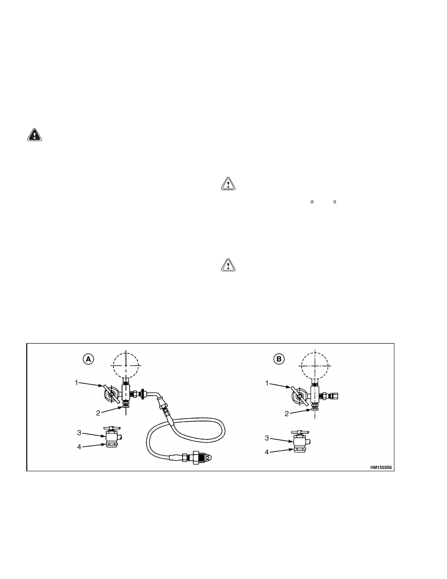
A. GAUGE WITH CHARGING HOSE
B. GAUGE WITHOUT CHARGING HOSE
1.
T-HANDLE
2.
BLEED VALVE
3.
GAS CHUCK
4.
SWIVEL NUT
Figure 1. Charging and Gauging Assemblies
2

1800 SRM 1036
Accumulator Maintenance
13. Let the precharge set for 10 to 15 minutes. This
will allow the gas temperature to stabilize. If the
desired precharge is exceeded, slowly open bleed
valve on gauge assembly. Close the bleed valve
when the correct value is obtained.
14. Remove gauging assembly by holding the gas
valve and loosening the swivel nut on the gaug-
ing assembly.
15. Replace gas valve cap and valve guard. Tighten
to 1.13 to 1.69 N•m (10 to 15 lbf in).
REMOVE
WARNING
Before disconnecting the hydraulic line, re-
lease pressure from the hydraulic circuit as
follows:
a. Shut OFF the engine and completely lower
the carriage. Install blocks at the wheels to
prevent the lift truck from moving.
b. Operate the lift/lower lever and the brake
pedals until the hydraulic pressure is re-
leased.
1.
Put tags for identification on the line.
2.
Slowly disconnect the hydraulic line from the ac-
cumulator to release any pressure slowly.
3.
Put cap on the line.
4.
Loosen screws and remove accumulator from the
frame brackets.
DISASSEMBLE
NOTE: Back T-handle on gauging assembly all the
way out before attaching gauging assembly to accu-
mulator gas valve. See Figure 2.
1.
Remove gas valve guard and gas valve cap.
2.
Close bleed valve on gauging assembly.
3.
Attach swivel nut on gauging assembly to gas
valve and tighten to 1.13 to 1.69 N•m (10 to
15 lbf in). Make sure not to loop or twist the hose.
4.
Turn T-handle on gauging assembly all the way
down to depress core in accumulator.
5.
Open bleed valve until all gas precharge is re-
lieved from the accumulator.
6.
Remove gauging assembly and gas valve.
7.
Lay accumulator horizontal and hold down with
a strap wrench or in a vise.
8.
Install three pins into holes in gas valve cap.
9.
Using a long bar, working against the pins, un-
screw the gas valve cap from the body.
10. Remove O-rings and backup rings from the hy-
draulic end cap.
WARNING
Never try to remove piston by applying com-
pressed air at opposite end.
11. Remove piston by pushing from hydraulic end
cap with a bar.
12. Remove V O-ring by lifting seal with a smooth
screwdriver or similar tool and moving the tool
around the piston several times while using the
other hand to work ring off the piston.
CLEAN
WARNING
Compressed air can move particles so they
cause injury to the user or to other personnel.
Make sure the path of the compressed air is
away from all personnel. Wear protective gog-
gles or a face shield to prevent injury to the
eyes.
NOTE: Bore must be clean of any particles detectable
to touch.
1.
Thoroughly clean metal parts in solvent and dry
with compressed air.
2.
Clean body bore with a clean, lint-free cloth
soaked in clean solvent.
INSPECT
1.
Inspect piston for cracks, burrs around O-ring
grooves, or damage.
2.
Using a light, examine body bore for scratches or
scoring.
3.
Inspect end caps for damaged threads or burrs on
O-ring grooves.
3
Accumulator Maintenance
1800 SRM 1036
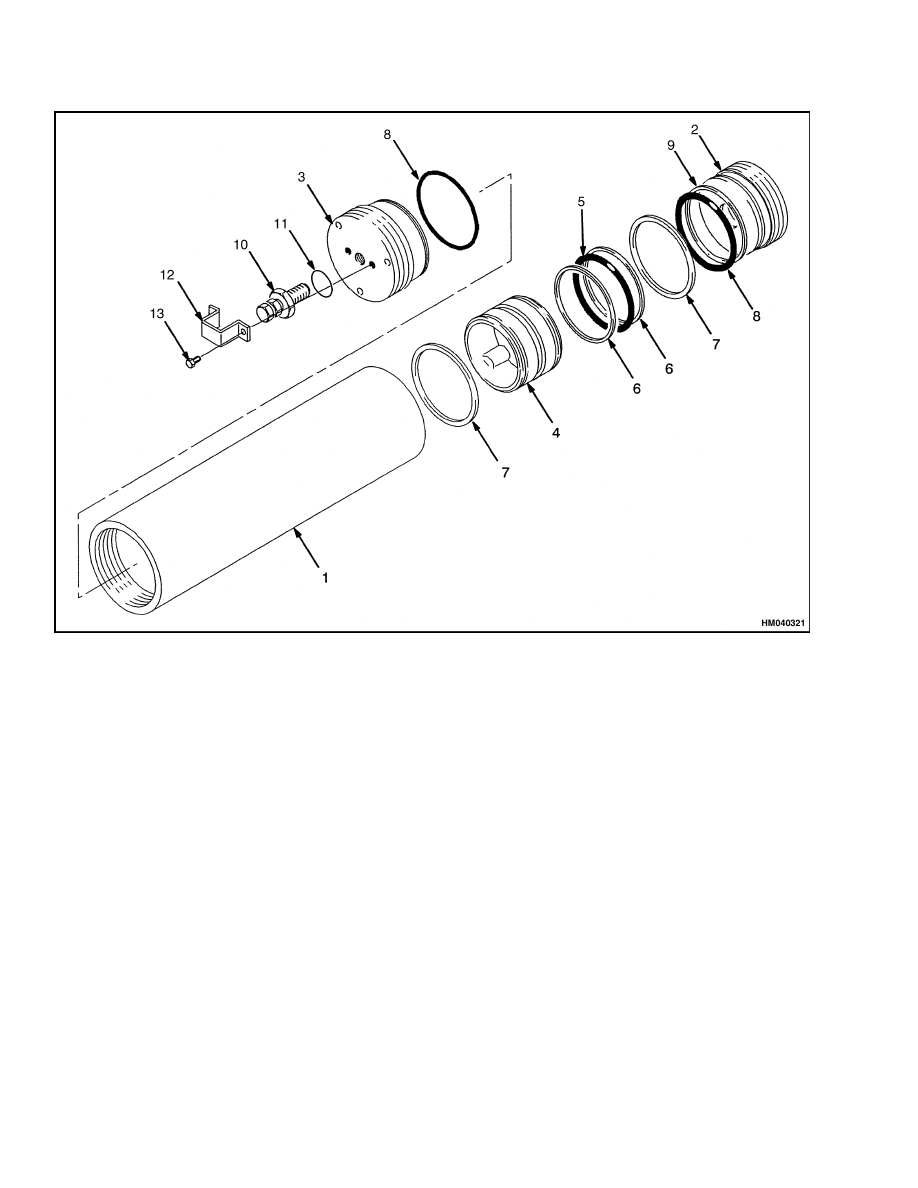
1.
SHELL
2.
HYDRAULIC END CAP
3.
GAS VALVE CAP
4.
PISTON
5.
V O-RING
6.
BACKUP WASHER
7.
WEAR RING
8.
O-RING
9.
BACKUP WASHER
10. GAS VALVE
11. O-RING
12. GAS VALVE GUARD
13. SCREW
Figure 2. Accumulator
REPAIR
NOTE: Minor nicks and scratches or light scoring of
the body bore can be removed by using crocus cloth.
1.
Dress bore until all apparent imperfections have
been removed.
2.
Replace Teflon wear rings, V O-rings, O-rings,
and backup washers.
ASSEMBLE
NOTE: Coat all internal parts with clean hydraulic
fluid before reassembly.
NOTE: Do not let V O-ring drag on threads. Piston
must go into bore exactly square and very slowly. V
O-ring will compress as it rides up the chamber if
done slowly, but may be damaged if forced quickly.
Piston should fit snug.
1.
With new V O-ring and Teflon rings on piston,
install piston (hollow side toward gas end) into
bore of body.
NOTE: Keep force against piston while tapping V
O-ring through bore chamber; otherwise, piston will
bounce back and damage the O-ring.
4

1800 SRM 1036
Accumulator Maintenance
2.
Use hammer and wood block to tap piston into
place until all of piston is 51 mm (2 in.) below
beginning of honed bore.
3.
Cover port opening to keep out dirt.
NOTE: O-ring sealing is not dependent on cap tight-
ness. Extreme tightness is not required. Cap should
be flush with end of body within 0.16 cm (0.063 in.)
to 0.27 cm (0.106 in.) above or below.
4.
Install new backup ring first and then new
O-ring on threaded end cap or caps and install
into body bore. End cap will stop against cham-
ber leading into honed bore.
REPLACE
NOTE: Always check the precharge before installing
a replacement accumulator on the truck.
1.
Replace the accumulator on the frame brackets.
2.
Tighten the bracket nuts.
3.
Connect the hydraulic line.
4.
Operate the system and check for leaks. Remove
air from the hydraulic system. See Brake System
Air Removal.
5

NOTES
____________________________________________________________
____________________________________________________________
____________________________________________________________
____________________________________________________________
____________________________________________________________
____________________________________________________________
____________________________________________________________
____________________________________________________________
____________________________________________________________
____________________________________________________________
____________________________________________________________
____________________________________________________________
____________________________________________________________
____________________________________________________________
____________________________________________________________
____________________________________________________________
____________________________________________________________
____________________________________________________________
____________________________________________________________
____________________________________________________________
6


TECHNICAL PUBLICATIONS
1800 SRM 1036
8/05 (3/05)(8/04)(7/04)(9/02) Printed in United Kingdom
Document Outline
Wyszukiwarka
Podobne podstrony:
1565789 1800SRM1117 (08 2005) UK EN
1568204 0700SRM1159 (08 2005) UK EN
1566043 0620SRM1115 (08 2005) UK EN
897653 1800SRM0566 (04 2005) UK EN
910091 1900SRM0097 (08 2005) UK EN
1510466 1800SRM0985 (05 2005) UK EN
1569718 4000SRM1160 (08 2005) UK EN
1531815 1800SRM1040 (03 2005) UK EN
1574068 1400SRM1171 (08 2005) UK EN
1466229 1800SRM0734 (05 2005) UK EN
1565653 2100SRM1116 (08 2005) UK EN
1596604 8000SRM1202 (08 2005) UK EN(1)
1531821 1800SRM1037 (03 2005) UK EN
1568204 0700SRM1159 (08 2005) UK EN
1566043 0620SRM1115 (08 2005) UK EN
897653 1800SRM0566 (04 2005) UK EN
więcej podobnych podstron