
© ISO 2001
Technical drawings — General principles of
presentation —
Part 30:
Basic conventions for views
Dessins techniques — Principes généraux de représentation —
Partie 30: Conventions de base pour les vues
SIS-2002-573
2001

ii
© ISO 2001 – All rights reserved
PDF disclaimer
This PDF file may contain embedded typefaces. In accordance with Adobe's licensing policy, this file may be printed or viewed but shall not be
edited unless the typefaces which are embedded are licensed to and installed on the computer performing the editing. In downloading this file,
parties accept therein the responsibility of not infringing Adobe's licensing policy. The ISO Central Secretariat accepts no liability in this area.
Adobe is a trademark of Adobe Systems Incorporated.
Details of the software products used to create this PDF file can be found in the General Info relative to the file; the PDF-creation parameters
were optimized for printing. Every care has been taken to ensure that the file is suitable for use by ISO member bodies. In the unlikely event
that a problem relating to it is found, please inform the Central Secretariat at the address given below.
© ISO 2001
All rights reserved. Unless otherwise specified, no part of this publication may be reproduced or utilized in any form or by any means, elec-
tronic or mechanical, including photocopying and microfilm, without permission in writing from either ISO at the address below or ISO's mem-
ber body in the country of the requester.
ISO copyright office
Case postale 56 • CH-1211 Geneva 20
Tel. + 41 22 749 01 11
Fax + 41 22 749 09 47
E-mail copyright@iso.ch
Web www.iso.ch
Printed in Switzerland

© ISO 2001 – All rights reserved
iii
ISO (the International Organization for Standardization) is a worldwide federation of national standards bodies (ISO
member bodies). The work of preparing International Standards is normally carried out through ISO technical
committees. Each member body interested in a subject for which a technical committee has been established has
the right to be represented on that committee. International organizations, governmental and non-governmental, in
liaison with ISO, also take part in the work. ISO collaborates closely with the International Electrotechnical
Commission (IEC) on all matters of electrotechnical standardization.
International Standards are drafted in accordance with the rules given in the ISO/IEC Directives, Part 3.
Draft International Standards adopted by the technical committees are circulated to the member bodies for voting.
Publication as an International Standard requires approval by at least 75 % of the member bodies casting a vote.
Attention is drawn to the possibility that some of the elements of this part of ISO 128 may be the subject of patent
rights. ISO shall not be held responsible for identifying any or all such patent rights.
International Standard ISO 128-30 was prepared by Technical Committee ISO/TC 10,
Technical product
documentation
, Subcommittee SC 1,
Basic conventions
.
This first edition is based on ISO 128:1982, clause 2 of which it cancels and replaces.
ISO 128 consists of the following parts, under the general title
Technical drawings — General principles of
presentation
:
—
Part 20: Basic conventions for lines
—
Part 21: Preparation of lines by CAD systems
—
Part 22: Basic conventions and applications for leader lines and reference lines
—
Part 23: Lines on construction drawings
—
Part 24: Lines on mechanical engineering drawings
—
Part 25: Lines on shipbuilding drawings
—
Part 30: Basic conventions for views
—
Part 34: Views on mechanical engineering drawings
—
Part 40: Basic conventions for cuts and sections
—
Part 44: Sections on mechanical engineering drawings
—
Part 50: Basic conventions for representing areas on cuts and sections
The following part is under preparation:
Part 1: Introduction and index.
Annexes A ,B and C form a normative part of this part of ISO 128.

iv
© ISO 2001 – All rights reserved
According to the replaced clause 2 of ISO 128:1982 three different methods of presenting views are allowed. In this
part of ISO 128, the method of using reference arrows has been selected as the preferred one. The first angle
projection method (formerly referred to as method E) and the third angle projection method (formerly referred to as
method A) are still to be regarded as normative. Annexes A and B of this part of ISO 128 give basic information on
the first and third angle projection methods; ISO 5456-2 specifies the rules in detail.

© ISO 2001 – All rights reserved
1
Technical drawings — General principles of presentation —
Part 30:
Basic conventions for views
1 Scope
This part of ISO 128 specifies the general principles for presenting views, applicable to all kinds of technical drawings
(mechanical, electrical, architectural, civil engineering, etc.), following the orthographic projection methods specified
in ISO 5456-2.
Attention has also been given in this part of ISO 128 to the requirements of reproduction, including microcopying in
accordance with ISO 6428.
The following normative documents contain provisions which, through reference in this text, constitute provisions of
this part of ISO 128. For dated references, subsequent amendments to, or revisions of, any of these publications do
not apply. However, parties to agreements based on this part of ISO 128 are encouraged to investigate the possibility
of applying the most recent editions of the normative documents indicated below. For undated references, the latest
edition of the normative document referred to applies. Members of ISO and IEC maintain registers of currently valid
International Standards.
ISO 128-24:1999,
Technical drawings — General principles of presentation — Part 24: Lines on mechanical
engineering drawings
.
ISO 3098-0,
Technical product documentation — Lettering — Part 0: General requirements
.
ISO 5456-2,
Technical drawings — Projection methods — Part 2: Orthographic representations
.
ISO 6428,
Technical drawings — Requirements for microcopying
.
ISO 10209-1,
Technical product documentation — Vocabulary — Part 1: Terms relating to technical drawings:
general and types of drawings
.
ISO 10209-2,
Technical product documentation — Vocabulary — Part 2: Terms relating to projection methods
.
ISO 81714-1,
Design of graphical symbols for use in the technical documentation of products — Part 1: Basic rules
.
For the purposes of this part of ISO 128, the terms and definitions given in ISO 10209-1 and ISO 10209-2 apply.
4 General
The most informative view of an object shall be used as the front or principal figure, taking into consideration, for
example, its functioning position, position of manufacturing or mounting.
Each view, with the exception of the front or principal figure (view, plan, principal figure), shall be given clear
identification with a capital letter, repeated near the reference arrow needed to indicate the direction of viewing for the
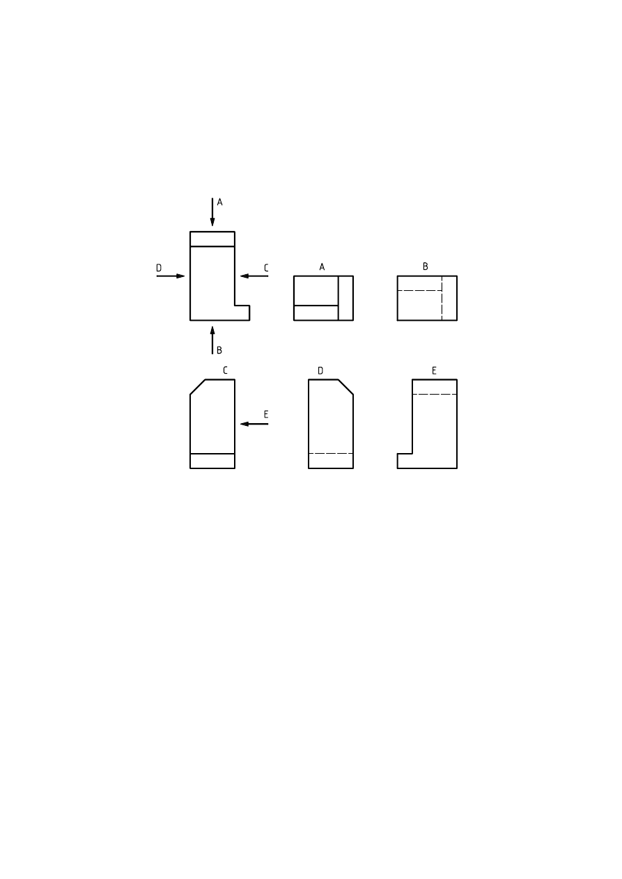
2
© ISO 2001 – All rights reserved
relevant view. Whatever the direction of viewing, the capital letter shall always be positioned in normal relation to the
direction of reading, and be indicated either above or on the right side of the reference arrow.
The reference arrow is defined in annex C (including the arc arrow, see clause 7), as is the lettering height of the
identification.
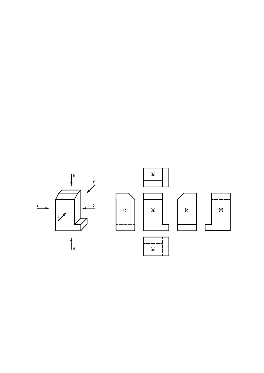
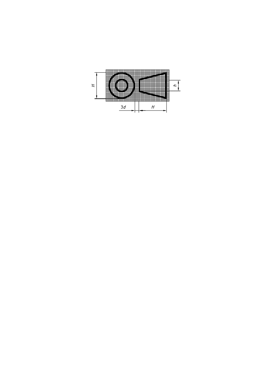
The designated views may be located irrespective of the principal figure. The capital letters identifying the referenced
views shall be placed immediately above the relevant views (see Figure 1).
5 Choice of views
When views (including cuts and sections) are needed, these shall be selected according to the following principles:
— limit the number of views (and cuts and sections) to the minimum necessary but sufficient to fully delineate the
object without ambiguity;
— avoid the need for hidden outlines and edges;
— avoid unnecessary repetition of a detail.
Figure 1 — Identification of referenced views
© ISO 2001 – All rights reserved
3
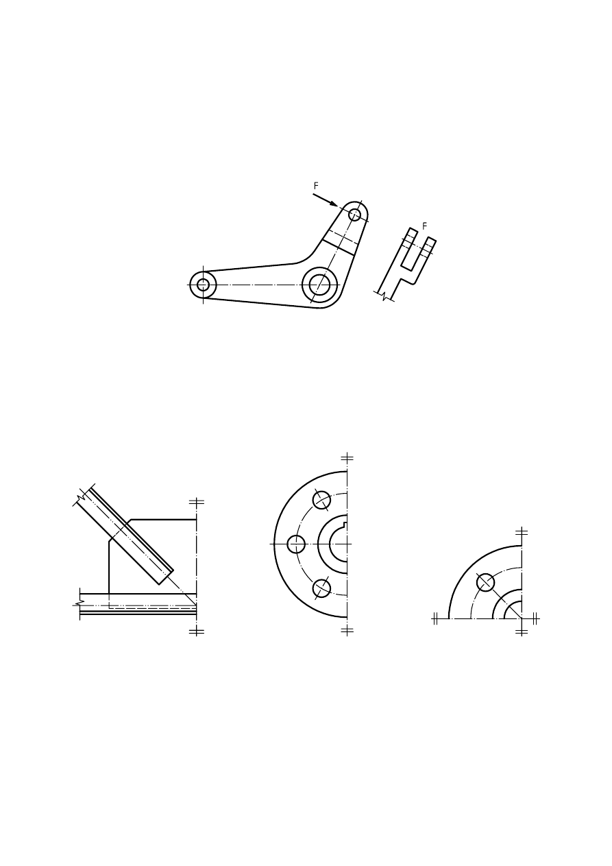
6 Partial views
6.1 General
Features needing specific illustration, but not meriting a full view, may be illustrated using a partial view limited by a
continuous narrow line with zigzags of type 01.1.19 according to ISO 128-24:1999 (see Figure 2).
6.2
Partial view of symmetrical parts
To save time and space, symmetrical objects may be drawn as a fraction of the whole [see Figure 3 a), b) and c)].
The line of symmetry is identified at each of its ends by two narrow short parallel lines drawn at right angles to it [see
Figure 3 a), b) and c)]. The graphical symbol for symmetry shall be drawn in accordance with clause C.4.
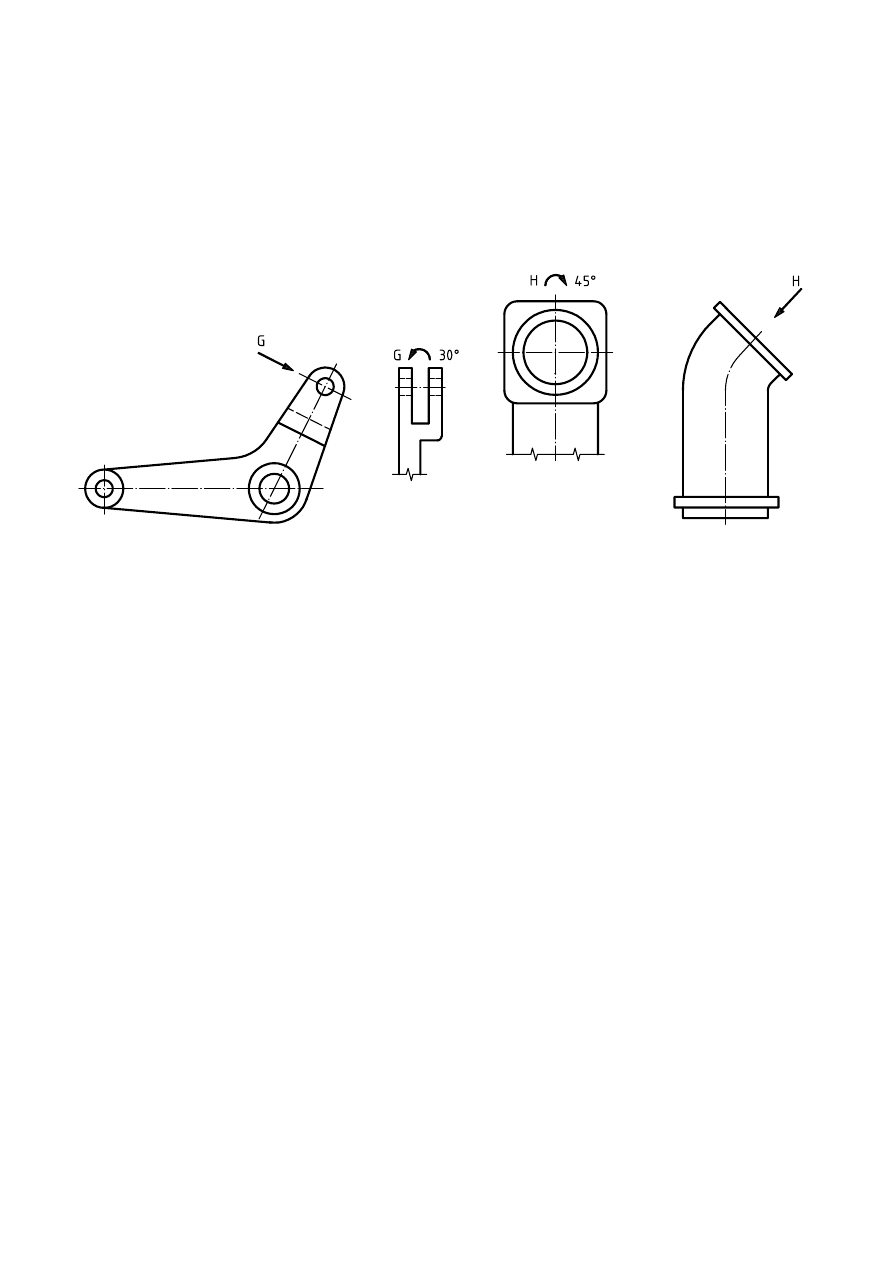
7 Special positions of view
When necessary, it is permitted to show the view in another position than that indicated by the reference arrow.
Figure 2 — Partial view
a) Example 1
b) Example 2
c) Example 3
Figure 3 — Partial view of symmetrical parts
4
© ISO 2001 – All rights reserved
The fact that the view is shown in another position should be clarified by an arc arrow showing the direction of rotation
according to Figure 4 a) and b). The angle of rotation of the view after the capital letter may be indicated. If used, the
sequence shall be:
“view identification — arc arrow — angle of rotation”
The arc arrow shall be drawn in accordance with clause C.3.
a) Example 1
b) Example 2
Figure 4 — Special view positions
© ISO 2001 – All rights reserved
5
Annex A
(normative)
First angle projection method
A.1 General
The first angle projection method is to be regarded as a requirement of this part of ISO 128. A more detailed
description of the first angle projection method is to be found in ISO 5456-2.
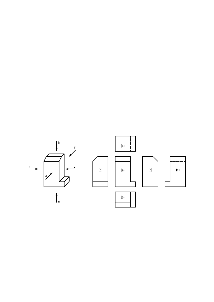
A.2 First angle projection method
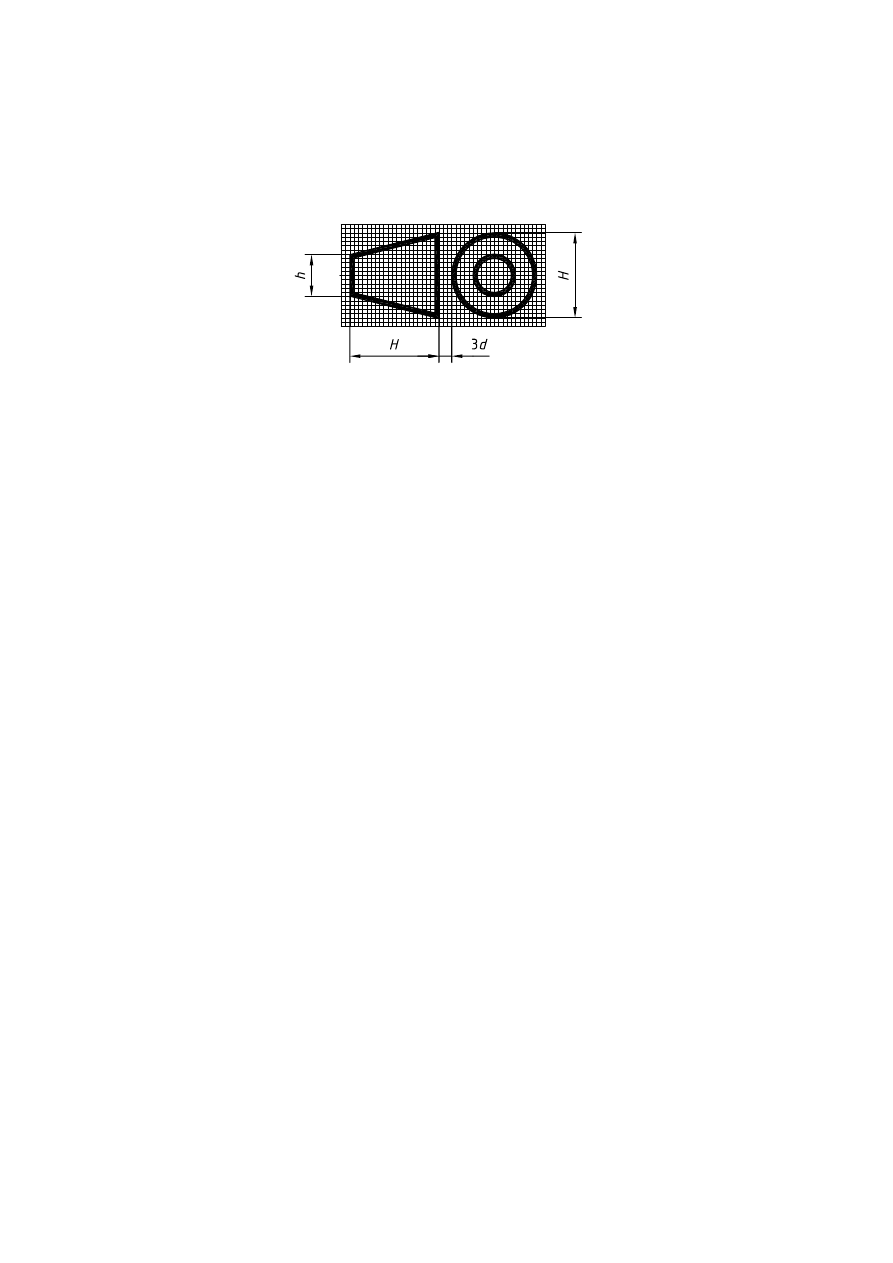
With reference to the front view, (a), the other views are arranged as follows (see Figure A.1):
— the view from above, (b), is placed underneath;
— the view from below, (e), is placed above;
— the view from the left, (c), is placed on the right;
— the view from the right, (d), is placed on the left;
— the view from the rear, (f), may be placed on the left or right, as convenient.
Figure A.1 — First angle projection method
6
© ISO 2001 – All rights reserved
A.3 Graphical symbol
The graphical symbol for the first angle projection method is shown in Figure A.2. The proportions and dimensions of
this graphical symbol are specified in ISO 5456-2.
Figure A.2 — Graphical symbol
© ISO 2001 – All rights reserved
7
Annex B
(normative)
Third angle projection method
B.1 General
The third angle projection method is to be regarded as a requirement of this part of ISO 128. A more detailed
description of the third angle projection method is to be found in ISO 5456-2.
B.2 Third angle projecion method
With reference to the front view, (a), the other views are arranged as follows (see Figure B.1):
— the view from above, (b), is placed above;
— the view from below, (e), is placed underneath;
— the view from the left, (c), is placed on the left;
— the view from the right, (d), is placed on the right;
— the view from the rear, (f), may be placed on the left or right, as convenient.
Figure B.1 — Third angle projection method
8
© ISO 2001 – All rights reserved
B.3 Graphical symbol
The graphical symbol for the third angle projection method is shown in Figure B.2. The proportions and dimensions
of this graphical symbol are specified in ISO 5456-2.
Figure B.2 — Graphical symbol
© ISO 2001 – All rights reserved
9
Annex C
(normative)
Graphical symbols
C.1 General
In order to harmonize the sizes of the graphical symbols specified in this part of ISO 128 with those of the other
inscriptions on the drawing (dimensions, tolerances, etc.), the rules given in ISO 81714-1 shall apply.
The view identification lettering height, , shall be larger than the normal lettering on the technical drawing by a factor
of
Within Figures C.1, C.2 and C.3, lettering type B, vertical, according to ISO 3098-0, applies. Other lettering types are
also permitted.
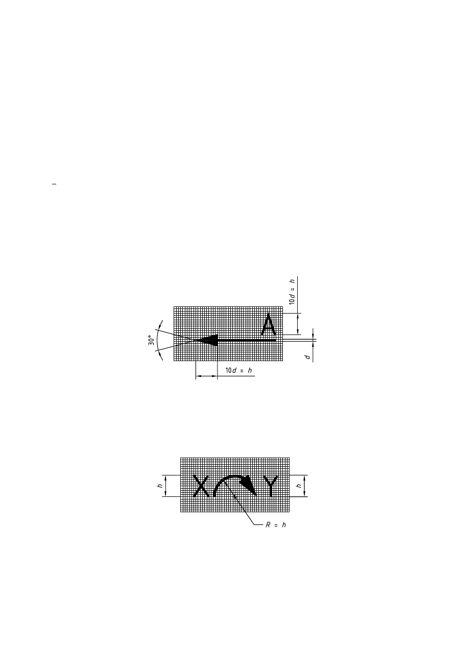
C.2 Reference arrow
See Figure C.1.
C.3 Arc arrow
See Figure C.2.
Figure C.1 — Graphical symbol for reference arrows
Figure C.2 — Graphical symbol for arc arrows
h
√
2.
10
© ISO 2001 – All rights reserved
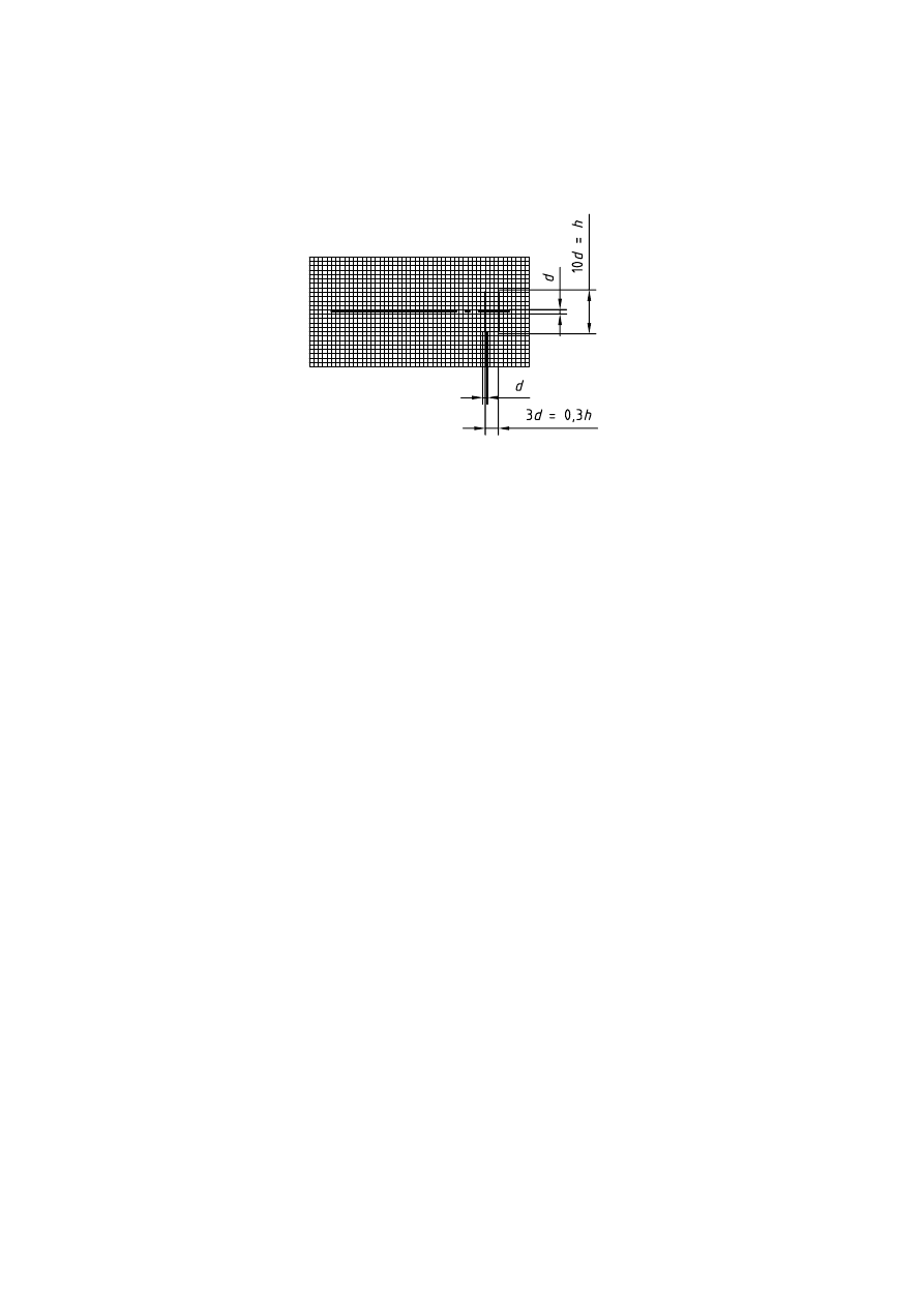
C.4 Symmetry
See Figure C.3.
Figure C.3 — Graphical symbol for symmetry

© ISO 2001 – All rights reserved
11
[1] ISO 128-20,
Technical drawings — General principles of presentation — Part 20: Basic conventions for lines
.

Wyszukiwarka
Podobne podstrony:
ISO128 34 views mechanical
FIDE Trainers Surveys 2012 03 30 Georg Mohr Methods & Principles of Defence
30 Struktury zaleznosci miedzy wskaznikami zrow rozw K Chmura
30 Wydatki rodziny
30 Tydzień zwykły, 30 środa
Fizyka 0 wyklad organizacyjny Informatyka Wrzesien 30 2012
geolog ogolna 30
Ustawa z 30 10 2002 r o ubezp społ z tyt wyp przy pracy i chor zawod
30 Obciążenia obiektów budowlanych, mostów drogowych i kolejowych
wyklad 29 i 30 tech bad
wyklad z kardiologii 30 11 2011
i 30 0 Przywodztwo w organizacji
F II wyklad 11 30 04 12
więcej podobnych podstron