
ENGINE MECHANICAL
CONTENTS
PRECAUTIONS ...............................................................3
Supplemental Restraint System (SRS)
...............3
Parts Requiring Angular Tightening.............................3
Liquid Gasket Application Procedure ..........................3
PREPARATION ...............................................................4
Special Service Tools ..................................................4
Commercial Service Tools ...........................................6
NOISE, VIBRATION AND HARSHNESS (NVH)
TROUBLESHOOTING .....................................................8
NVH Troubleshooting Chart - Engine Noise ...............9
OUTER COMPONENT PARTS .....................................10
Removal and Installation ...........................................10
MEASUREMENT OF COMPRESSION PRESSURE ....13
OIL PAN.........................................................................14
Removal.....................................................................14
Installation..................................................................16
TIMING BELT ................................................................17
Components...............................................................17
Removal.....................................................................18
Inspection...................................................................20
BELT TENSIONER AND TENSIONER SPRING
..........20
Installation..................................................................21
Tension Adjustment....................................................22
..................................22
AFTER ENGINE OVERHAUL OR ENGINE
REASSEMBLY (WITH ROCKER COVERS
REMOVED)
.............................................................23
OIL SEAL.......................................................................25
Replacement..............................................................25
.....................................................25
.........................25
.............................................26
....................................................26
......................................................26
CYLINDER HEAD..........................................................27
Components...............................................................27
Removal.....................................................................28
Disassembly...............................................................30
Inspection...................................................................31
...............................31
....................................32
..............................................32
.......................................32
........................32
............................................33
...........................33
....................................33
................................34
.........................................................35
REPLACING VALVE SEAT FOR SERVICE PARTS
....36
...............................................36
.......................................................37
......................37
....................................38
Assembly ...................................................................38
Installation..................................................................39
ENGINE ASSEMBLY.....................................................43
Removal and Installation ...........................................43
...............................................44
CYLINDER BLOCK .......................................................47
Components...............................................................47
Removal and Installation ...........................................48
Disassembly...............................................................48
....................................48
Inspection...................................................................49
PISTON AND PISTON PIN CLEARANCE
..................49
............................49
..........................................49
CONNECTING ROD BEND AND TORSION
...............50
CYLINDER BLOCK DISTORTION AND WEAR
...........50
..............................51
.........................................................52
...........................................53
CONNECTING ROD BUSHING CLEARANCE
(SMALL END)
..........................................................55
REPLACEMENT OF CONNECTING ROD
BUSHING (SMALL END)
..........................................55
Assembly ...................................................................56
..................................................................56
GI
MA
LC
EC
FE
AT
AX
SU
BR
ST
RS
BT
HA
SC
EL
IDX

.........................................................56
............................58
SERVICE DATA AND SPECIFICATIONS (SDS) .........59
General Specifications...............................................59
Cylinder Head ............................................................60
Valve ..........................................................................60
....................................................................60
.......................................................61
....................................61
.........................................................61
......................61
Valve Seat..................................................................62
..............................................62
...........................................63
Camshaft and Camshaft Bearing ..............................64
Cylinder Block............................................................65
Piston, Piston Ring and Piston Pin ...........................66
................................................66
.........................................................66
............................................................67
Connecting Rod .........................................................67
Crankshaft..................................................................67
Available Main Bearing..............................................68
.............................................68
..................................68
.............................................68
...........................................................68
Available Connecting Rod Bearing............................69
CONNECTING ROD BEARING UNDERSIZE
.............69
Miscellaneous Components.......................................69
...........................................69
CONTENTS
(Cont’d)
EM-2
Supplemental Restraint System (SRS) “AIR
BAG” and “SEAT BELT PRE-TENSIONER”
NDEM0041
The Supplemental Restraint System such as “AIR BAG” and “SEAT BELT PRE-TENSIONER” used along with
a seat belt, helps to reduce the risk or severity of injury to the driver and front passenger for certain types of
collision. The Supplemental Restraint System consists of driver air bag module (located in the center of the
steering wheel), front passenger air bag module (located on the instrument panel on passenger side), seat
belt pre-tensioners, a diagnosis sensor unit, warning lamp, wiring harness, and spiral cable.
Information necessary to service the system safely is included in the RS section of this Service Manual.
WARNING:
쐌
To avoid rendering the SRS inoperative, which could increase the risk of personal injury or death
in the event of a collision which would result in air bag inflation, all maintenance should be per-
formed by an authorized NISSAN dealer.
쐌
Improper maintenance, including incorrect removal and installation of the SRS, can lead to per-
sonal injury caused by unintentional activation of the system. For removal of Spiral Cable and Air
Bag Module, see the RS section.
쐌
Do not use electrical test equipment on any circuit related to the SRS unless instructed to in this
Service Manual. SRS wiring harnesses can be identified by yellow harness connectors.
Parts Requiring Angular Tightening
NDEM0001
쐌
Use an angle wrench for the final tightening of the following
engine parts:
a)
Cylinder head bolts
b)
Connecting rod cap nuts
쐌
Do not use a torque value for final tightening.
쐌
The torque value for these parts are for a preliminary step.
쐌
Ensure thread and seat surfaces are clean and coated with
engine oil.
SEM371C
AEM080
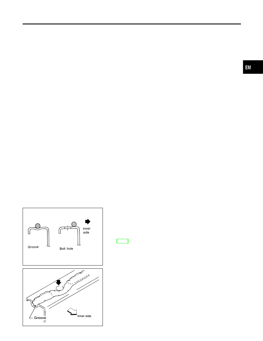
Liquid Gasket Application Procedure
NDEM0002
1)
Use a scraper to remove all traces of old liquid gasket from
mating surfaces and grooves. Also completely clean any oil
stains from these portions.
2)
Apply a continuous bead of liquid gasket to mating surfaces.
Use Genuine RTV Silicone Sealant or equivalent. Refer to
GI-48, “Recommended Chemical Products and Sealants”.
쐌
Be sure liquid gasket is 3.5 to 4.5 mm (0.138 to 0.177 in) dia.
(for oil pan).
쐌
Be sure liquid gasket is 2.0 to 3.0 mm (0.079 to 0.118 in) dia.
(in areas except oil pan).
3)
Apply liquid gasket to inner surface around hole perimeter area
(unless otherwise specified).
4)
Assembly should be done within 5 minutes after coating.
5)
Wait at least 30 minutes before refilling engine oil and engine
coolant.
GI
MA
LC
EC
FE
AT
AX
SU
BR
ST
RS
BT
HA
SC
EL
IDX
PRECAUTIONS
Supplemental Restraint System (SRS) “AIR BAG” and “SEAT BELT PRE-TENSIONER”
EM-3
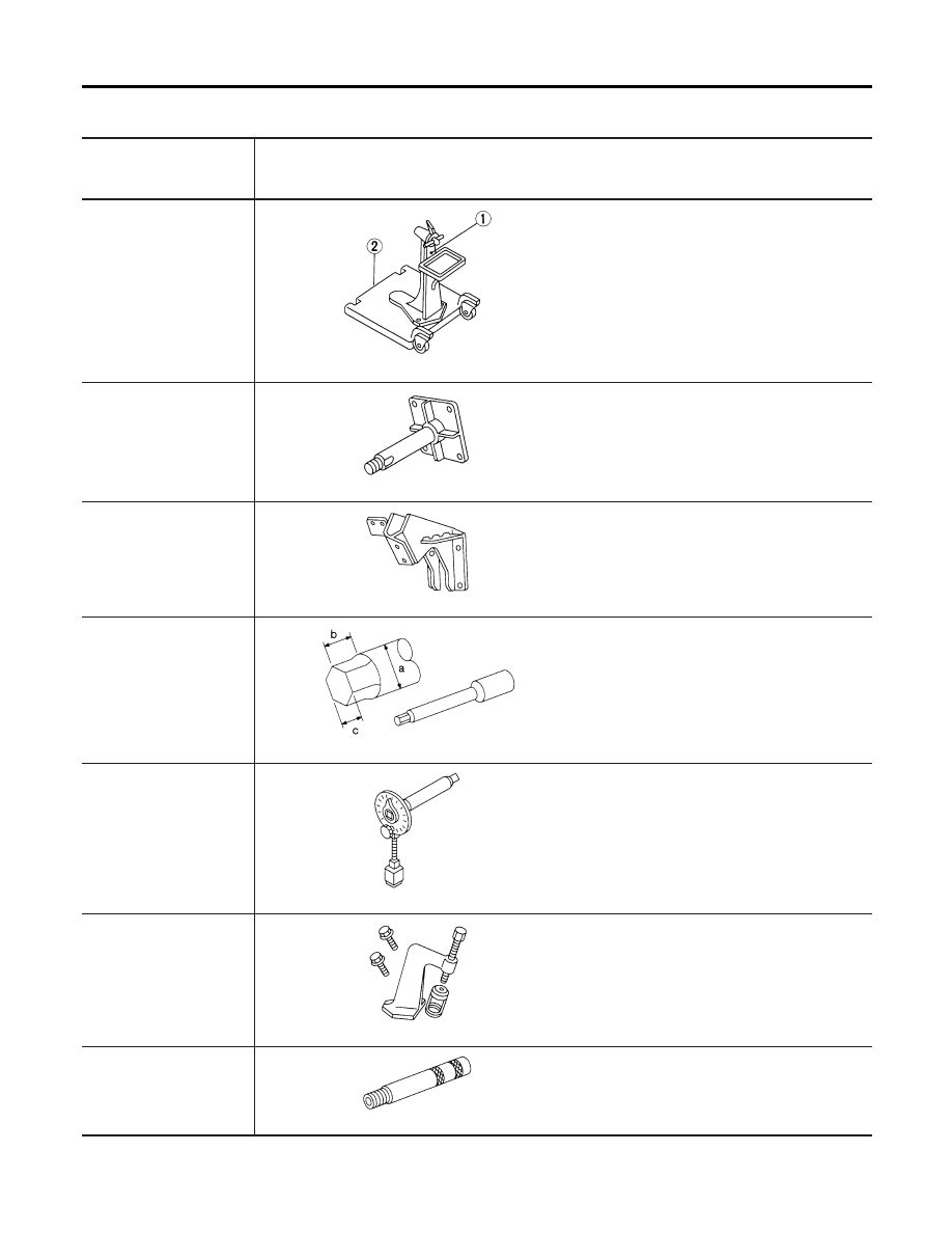
Special Service Tools
NDEM0003
The actual shapes of Kent-Moore tools may differ from those of special service tools illustrated here.
Tool number
(Kent-Moore No.)
Tool name
Description
ST0501S000
(
—
)
Engine stand assembly
1 ST05011000
(
—
)
Engine stand
2 ST05012000
(
—
)
Base
NT042
Disassembling and assembling
KV10106500
(
—
)
Engine stand shaft
NT028
KV10110001
(
—
)
Engine sub-attachment
NT032
ST10120000
(J24239-01)
Cylinder head bolt wrench
NT583
Loosening and tightening cylinder head bolt
a: 13 mm (0.51 in) dia.
b: 12 mm (0.47 in)
c: 10 mm (0.39 in)
KV10112100
(BT8653-A)
Angle wrench
NT014
Tightening bearing cap, cylinder head bolts,
etc.
KV10110600
(J33986)
Valve spring compressor
NT033
Disassembling and assembling valve compo-
nents
KV10107501
(
—
)
Valve oil seal drift
NT025
Installing valve oil seal
PREPARATION
Special Service Tools
EM-4
Tool number
(Kent-Moore No.)
Tool name
Description
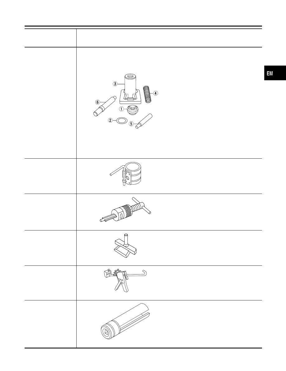
KV10110300
(
—
)
Piston pin press stand
assembly
1 KV10110310
(
—
)
Cap
2 KV10110330
(
—
)
Spacer
3 ST13030020
(
—
)
Press stand
4 ST13030030
(
—
)
Spring
5 KV10110340
(
—
)
Drift
6 KV10110320
(
—
)
Center shaft
NT036
Disassembling and assembling piston with
connecting rod
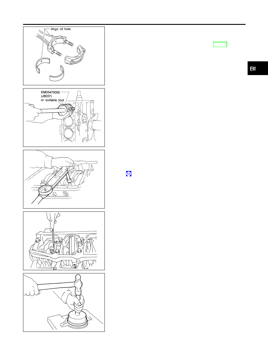
EM03470000
(J8037)
Piston ring compressor
NT044
Installing piston assembly into cylinder bore
ST16610001
(J23907)
Pilot bushing puller
NT045
Removing crankshaft pilot bushing
KV10111100
(J37228)
Seal cutter
NT046
Removing oil pan
WS39930000
(
—
)
Tube presser
NT052
Pressing the tube of liquid gasket
KV10117100
(J3647-A)
Heated oxygen sensor
wrench
NT379
Loosening or tightening front heated oxygen
sensor
with 22 mm (0.87 in) hexagon nut
GI
MA
LC
EC
FE
AT
AX
SU
BR
ST
RS
BT
HA
SC
EL
IDX
PREPARATION
Special Service Tools (Cont’d)
EM-5
Tool number
(Kent-Moore No.)
Tool name
Description
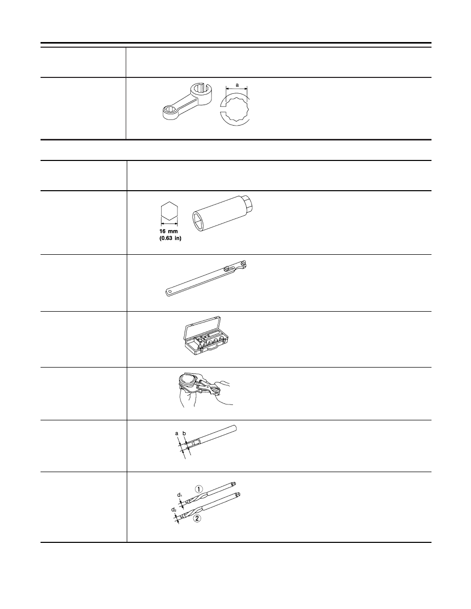
KV10114400
(J38365)
Heated oxygen sensor
wrench
NT636
Loosening or tightening rear heated oxygen
sensor
a: 22 mm (0.87 in)
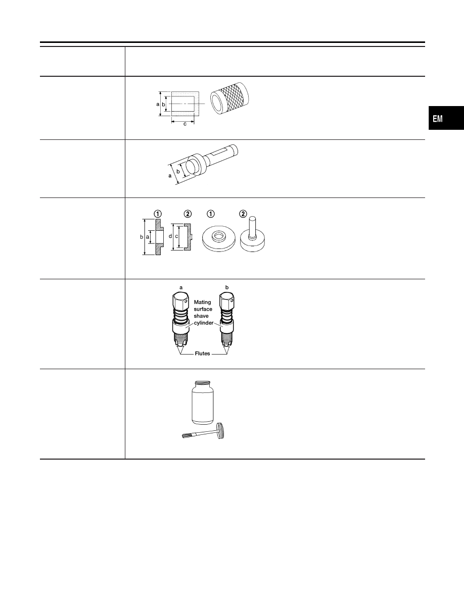
Commercial Service Tools
NDEM0004
Tool number
(Kent-Moore No.)
Tool name
Description
Spark plug wrench
NT047
Removing and installing spark plug
Pulley holder
NT035
Holding camshaft pulley while tightening or
loosening camshaft bolt
Valve seat cutter set
NT048
Finishing valve seat dimensions
Piston ring expander
NT030
Removing and installing piston ring
Valve guide drift
NT015
Removing and installing valve guide
Intake & Exhaust:
a = 10.5 mm (0.413 in) dia.
b = 6.6 mm (0.260 in) dia.
Valve guide reamer
NT016
Reaming valve guide 1 or hole for oversize
valve guide 2
Intake:
d
1
= 7.0 mm (0.276 in) dia.
d
2
= 11.2 mm (0.441 in) dia.
Exhaust:
d
1
= 8.0 mm (0.315 in) dia.
d
2
= 12.2 mm (0.480 in) dia.
PREPARATION
Special Service Tools (Cont’d)
EM-6
Tool number
(Kent-Moore No.)
Tool name
Description
Camshaft oil seal drift
NT613
Installing camshaft oil seal
a: 60 mm (2.36 in) dia.
b: 44.5 mm (1.752 in) dia.
c: 75 mm (2.95 in)
Front oil seal drift
NT049
Installing front oil seal
a: 52 mm (2.05 in) dia.
b: 44 mm (1.73 in) dia.
Rear oil seal drift
NT719
Installing rear oil seal
a: 46 mm (1.81 in)
b: 110 mm (4.33 in)
c: 84 mm (3.31 in)
d: 96 mm (3.78 in)
(J-43897–18)
(J-43897–12)
Oxygen Sensor Thread
Cleaner
AEM488
Reconditioning the exhaust system threads
before installing a new oxygen sensor. Use
with anti-seize lubricant shown below
a: J-43897–18 18mm diameter, for Zirconia
oxygen sensor
a: J-43897–12 12mm diameter, for Titania
oxygen sensor
Anti-seize lubricant (Per-
matex
姟
133AR or equiva-
lent meeting MIL specifica-
tion MIL-A-907)
AEM489
Lubricating oxygen sensor thread cleaning tool
when reconditioning exhaust system threads
GI
MA
LC
EC
FE
AT
AX
SU
BR
ST
RS
BT
HA
SC
EL
IDX
PREPARATION
Commercial Service Tools (Cont’d)
EM-7
NDEM0039
AEM413
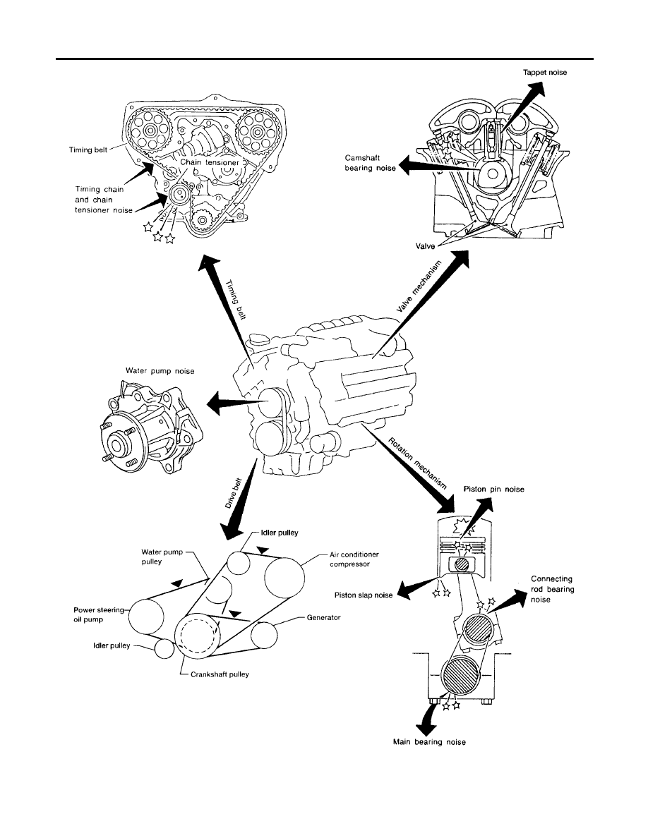
NOISE, VIBRATION AND HARSHNESS (NVH) TROUBLESHOOTING
EM-8
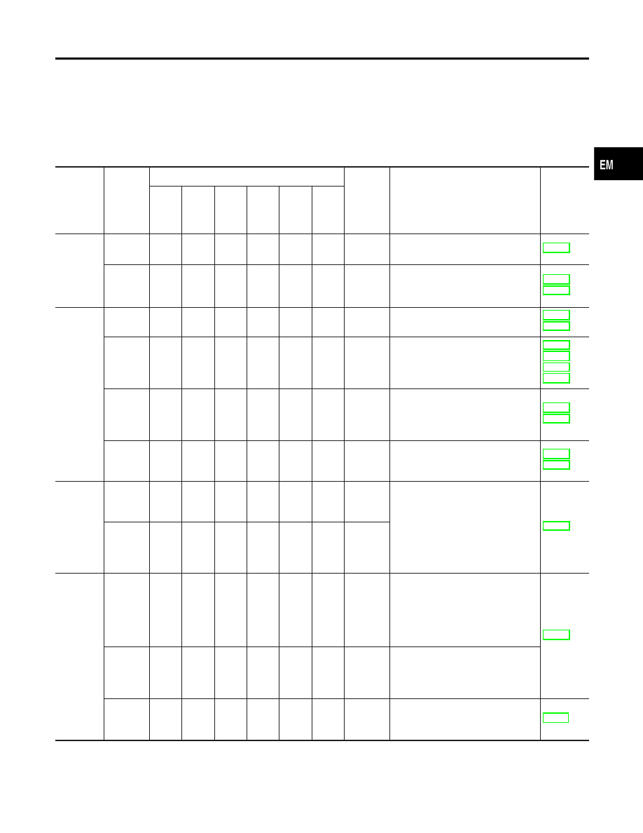
NVH Troubleshooting Chart — Engine Noise
NDEM0039S01
Use the chart below to help you find the cause of the symptom.
1.
Locate the area where noise occurs.
2.
Confirm the type of noise.
3.
Specify the operating condition of engine.
4.
Check specified noise source.
If necessary, repair or replace these parts.
Location
of noise
Type of
noise
Operating condition of engine
Source of
noise
Check item
Refer-
ence
page
Before
warm-up
After
warm-up
When
starting
When
idling
When
racing
While
driving
Top of
engine
Rocker
cover
Cylinder
head
Ticking or
clicking
C
A
—
A
B
—
Tappet
noise
Hydraulic valve lifter
EM-39 *1
Rattle
C
A
—
A
B
C
Camshaft
bearing
noise
Camshaft journal clearance
Camshaft runout
Crank-
shaft pul-
ley
Cylinder
block
(Side of
engine)
Oil pan
Slap or
knock
—
A
—
B
B
—
Piston
pin noise
Piston and piston pin clearance
Connecting rod bushing clearance
Slap or
rap
A
—
—
B
B
A
Piston
slap
noise
Piston-to-bore clearance
Piston ring side clearance
Piston ring end gap
Connecting rod bend and torsion
Knock
A
B
C
B
B
B
Connect-
ing rod
bearing
noise
Connecting rod bushing clearance
(Small end)
Connecting rod bearing clearance
(Big end)
Knock
A
B
—
A
B
C
Main
bearing
noise
Main bearing oil clearance
Crankshaft runout
Timing
belt cover
Whine or
hissing
C
A
—
A
A
—
Timing
belt noise
(too tight)
Loose timing belt
Belt contacting case
Clatter
A
B
—
C
A
—
Timing
belt noise
(too
loose)
Front of
engine
Squeak-
ing or
fizzing
A
B
—
B
—
C
Other
drive
belts
(Sticking
or slip-
ping)
Drive belts deflection
Creaking
A
B
A
B
A
B
Other
drive
belts
(Slipping)
Idler pulley bearing operation
Squall
Creak
A
B
—
B
A
B
Water
pump
noise
Water pump operation
A: Closely related
B: Related
C: Sometimes related
—: Not related
*1: Step 19 in “Installation”, “CYLINDER HEAD”
GI
MA
LC
EC
FE
AT
AX
SU
BR
ST
RS
BT
HA
SC
EL
IDX
NOISE, VIBRATION AND HARSHNESS (NVH) TROUBLESHOOTING
NVH Troubleshooting Chart — Engine Noise
EM-9
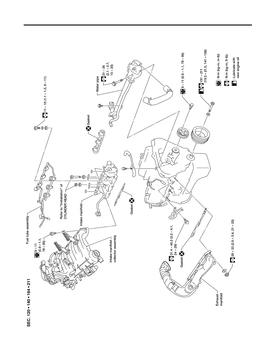
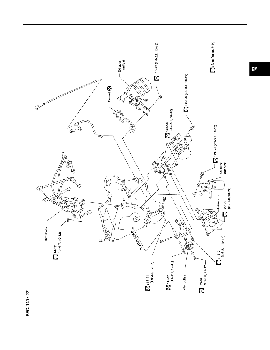
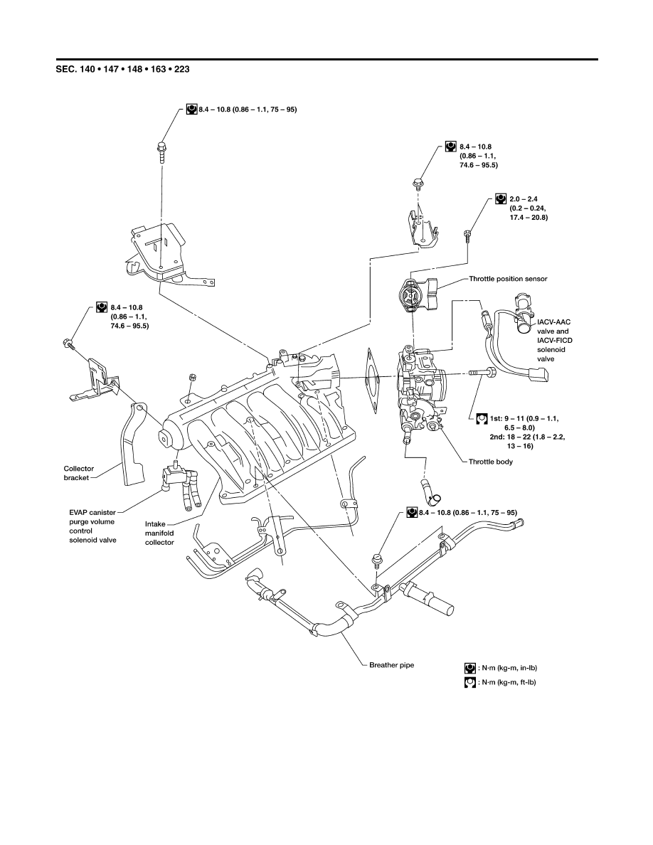
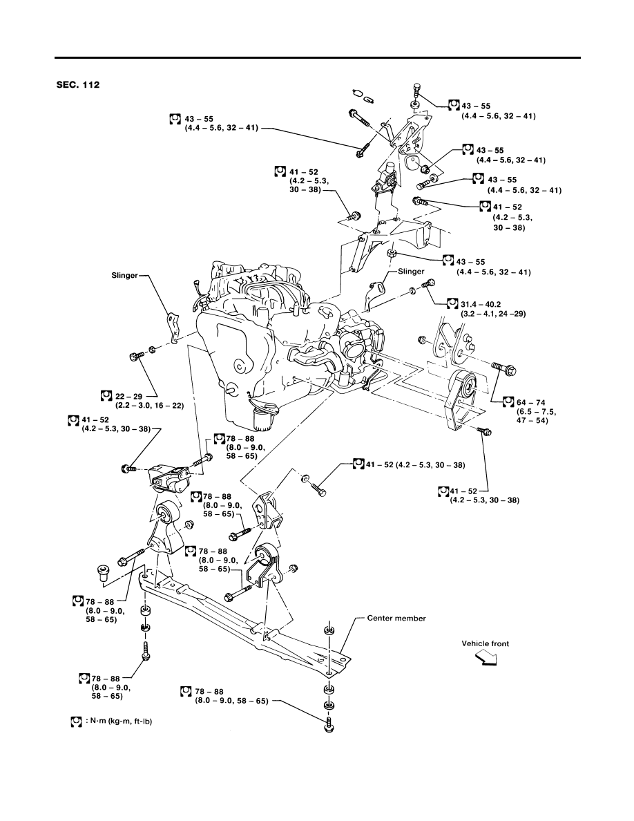
Removal and Installation
NDEM0005
WEM130
OUTER COMPONENT PARTS
Removal and Installation
EM-10
WEM143
GI
MA
LC
EC
FE
AT
AX
SU
BR
ST
RS
BT
HA
SC
EL
IDX
OUTER COMPONENT PARTS
Removal and Installation (Cont’d)
EM-11
WEM127
OUTER COMPONENT PARTS
Removal and Installation (Cont’d)
EM-12
NDEM0006
AEC800A
1.
Warm up engine.
2.
Turn ignition switch OFF.
3.
Release fuel pressure.
Refer to EC-35, “ Fuel Pressure Release”.
4.
Remove all spark plugs.
쐌
Clean area around plug with compressed air before
removing the spark plug.
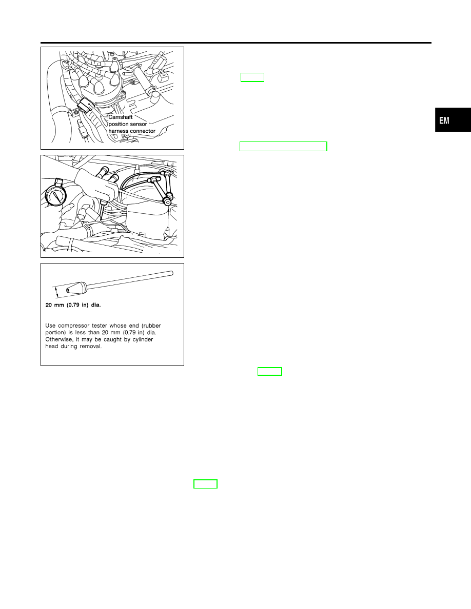
5.
Disconnect the camshaft position sensor harness connector at
the distributor.
6.
Remove fuel injector fuse 33 located in engine room.
Refer to “Terminal Arrangement”.
SEM814C
SEM387C
7.
Attach a compression tester to No. 1 cylinder.
8.
Depress accelerator pedal fully to keep throttle valve wide
open.
9.
Crank engine and record highest gauge indication.
10. Repeat the measurement on each cylinder as shown above.
쐌
Always use a fully-charged battery to obtain specified
engine speed.
Compression pressure: kPa (kg/cm
2
, psi)/300 rpm
Standard
1,196 (12.2, 173)
Minimum
883 (9.0, 128)
Difference limit between cylinders
98 (1.0, 14)
11. If cylinder compression in one or more cylinders is low, pour a
small amount of engine oil into cylinders through spark plug
holes and retest compression.
쐌
If adding oil improves cylinder compression, piston rings
may be worn or damaged. If so, replace piston rings after
checking piston.
쐌
If pressure stays low, a valve may be sticking or seating
improperly. Inspect and repair valve and valve seat. Refer
to “Valve”, EM-60. If valve or valve seat is damaged
excessively, replace them.
쐌
If compression in any two adjacent cylinders is low and if
adding oil does not improve compression, there is leak-
age past the gasket surface. If so, replace cylinder head
gasket.
12. Reinstall spark plugs, fuel injector fuse, fuel pump fuse and
reconnect camshaft position sensor harness connector at the
distributor.
13. Erase the DTC stored in ECM.
CAUTION:
Always erase the DTC after checking compression. Refer to
EC-61, “How to Erase Emission-Related Diagnostic Informa-
tion”.
GI
MA
LC
EC
FE
AT
AX
SU
BR
ST
RS
BT
HA
SC
EL
IDX
MEASUREMENT OF COMPRESSION PRESSURE
EM-13
Removal
NDEM0007
WARNING:
쐌
Place vehicle on a flat and solid surface.
쐌
Place chocks at front and rear of rear wheels.
쐌
You should not remove oil pan until exhaust system and
cooling system have completely cooled off.
Otherwise, you may burn yourself and/or fire may break
out in the fuel line.
쐌
When removing front and/or rear engine mounting bolts or
nuts, lift engine slightly to ensure safety.
CAUTION:
쐌
In lifting engine, be careful not to hit against adjacent
parts, especially against accelerator wire casing end,
brake tube and brake master cylinder.
1.
Drain engine oil.
2.
Remove engine lower covers.
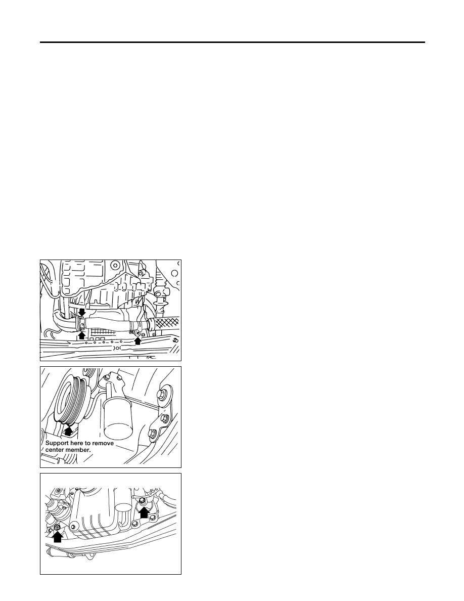
WEM101
3.
Remove exhaust tube fixing nuts and exhaust tube.
AEM003
4.
Support engine at crankshaft pulley with a suitable jack and
block or from above with a suitable support bar or hoist.
쐌
Be careful not to damage crankshaft pulley.
AEM450
5.
Remove engine mounting insulator bolts and nuts.
OIL PAN
Removal
EM-14
AEM073
6.
Remove the rear A/C refrigerant lines support bracket bolts, if
so equipped.
AEM070
7.
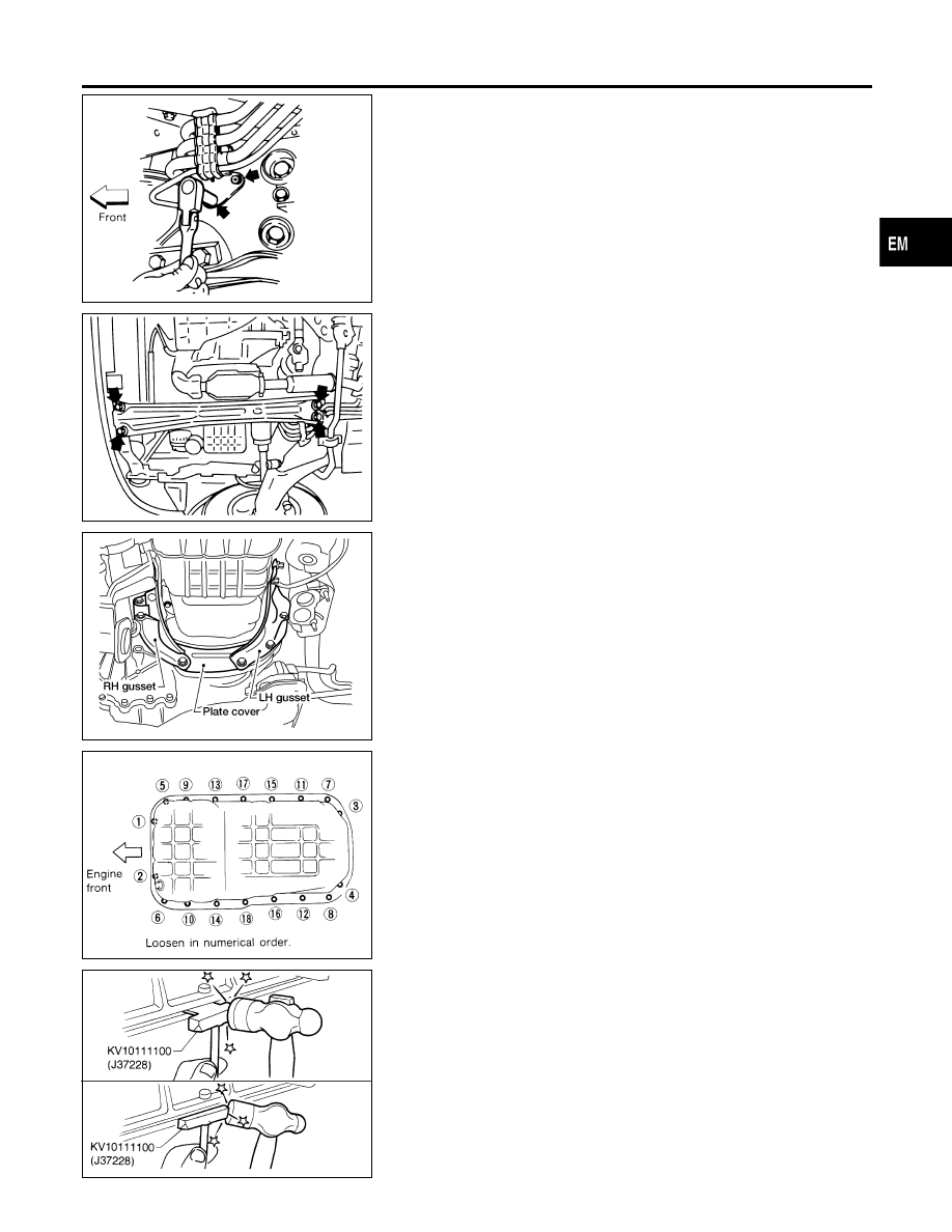
Remove center member.
AEM451
8.
Remove LH and RH gusset from engine block and transmis-
sion.
9.
Remove plate cover.
SEM045E
10. Remove oil pan bolts in numerical order.
SEM365E
11. Remove oil pan.
a.
Insert Tool between cylinder block and oil pan.
쐌
Do not drive seal cutter into oil pump or rear oil seal
retainer portion, or aluminum mating face will be dam-
aged.
쐌
Do not insert screwdriver, or oil pan flange will be
deformed.
b.
Slide Tool by tapping its side with a hammer, and remove oil
pan.
GI
MA
LC
EC
FE
AT
AX
SU
BR
ST
RS
BT
HA
SC
EL
IDX
OIL PAN
Removal (Cont’d)
EM-15
SEM350B
Installation
NDEM0008
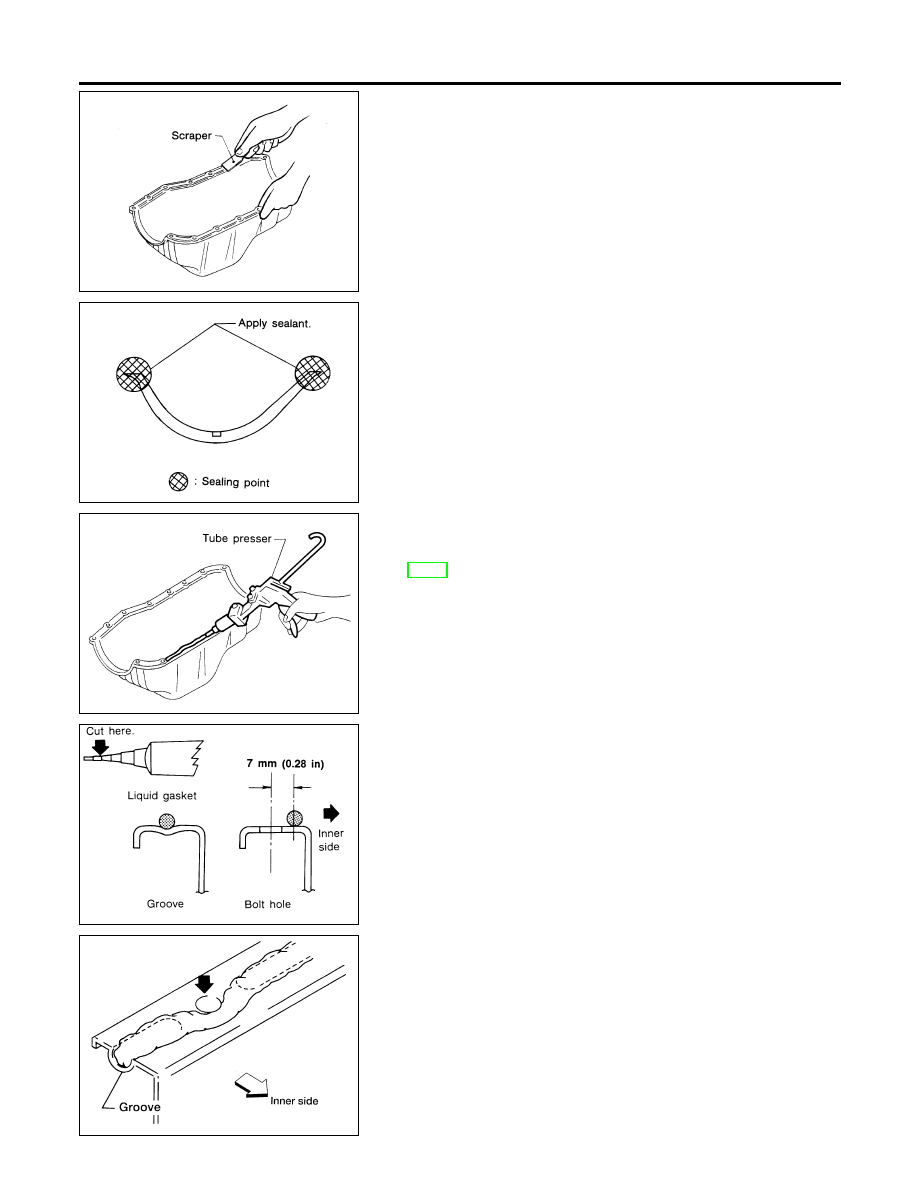
1.
Before installing oil pan, remove all traces of liquid gasket from
mating surface using a scraper.
쐌
Also remove traces of liquid gasket from mating surface of
cylinder block.
SEM894B
2.
Apply sealant to oil pump gasket and rear oil seal retainer
gasket.
SEM351B
3.
Apply a continuous bead of liquid gasket to mating surface of
oil pan.
쐌
Use Genuine RTV Silicone Sealant or equivalent. Refer to
GI-48, “Recommended Chemical Products and Sealants”.
SEM015E
AEM080
쐌
Be sure liquid gasket is 3.5 to 4.5 mm (0.138 to 0.177 in)
wide.
4.
Apply liquid gasket to inner sealing surface as shown in figure.
쐌
Attaching should be done within 5 minutes after coating.
5.
Install oil pan.
쐌
Install bolts/nuts in their reverse order of removal.
쐌
Wait at least 30 minutes before refilling engine oil.
OIL PAN
Installation
EM-16
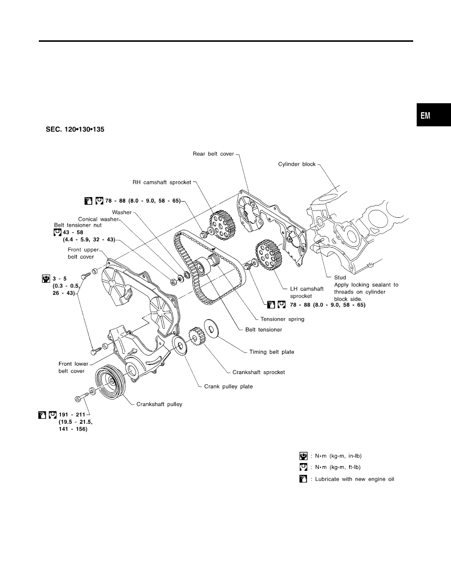
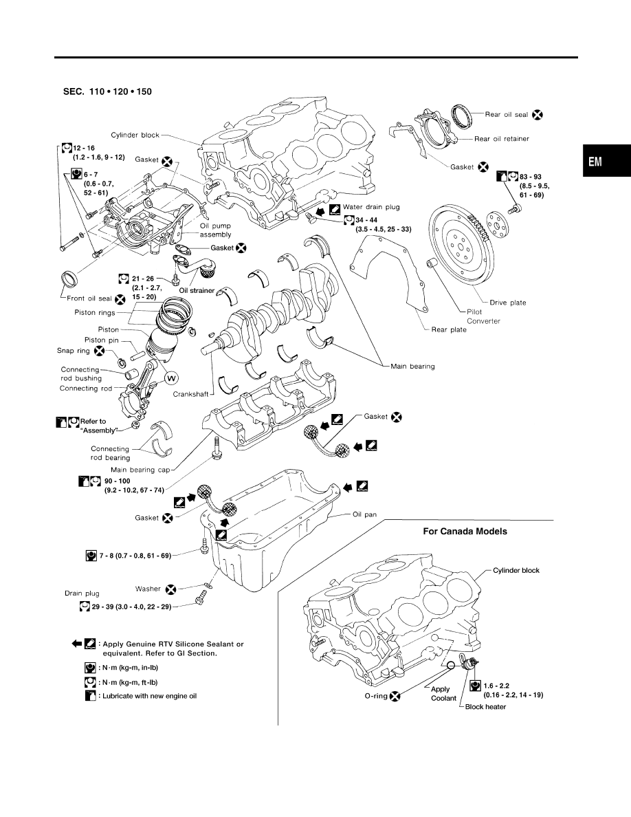
Components
NDEM0009
CAUTION:
쐌
Do not bend or twist timing belt.
쐌
After removing timing belt, do not turn crankshaft and camshaft separately because valves will
strike piston heads.
쐌
Make sure that timing belt, camshaft sprocket, crankshaft sprocket and belt tensioner are clean and
free from oil and water.
쐌
Installation should be carried out when engine is cold.
SEM311FA
GI
MA
LC
EC
FE
AT
AX
SU
BR
ST
RS
BT
HA
SC
EL
IDX
TIMING BELT
Components
EM-17
Removal
NDEM0010
1.
Jack up the vehicle front and support with safety stand.
2.
Remove engine under cover.
3.
Remove front RH wheel and engine side cover.
4.
Drain engine coolant from radiator. Refer to MA-14, “Changing
Engine Coolant”.
5.
Remove the following belts.
쐌
Compressor drive belt
쐌
Generator drive belt
쐌
Power steering pump drive belt
WEM129
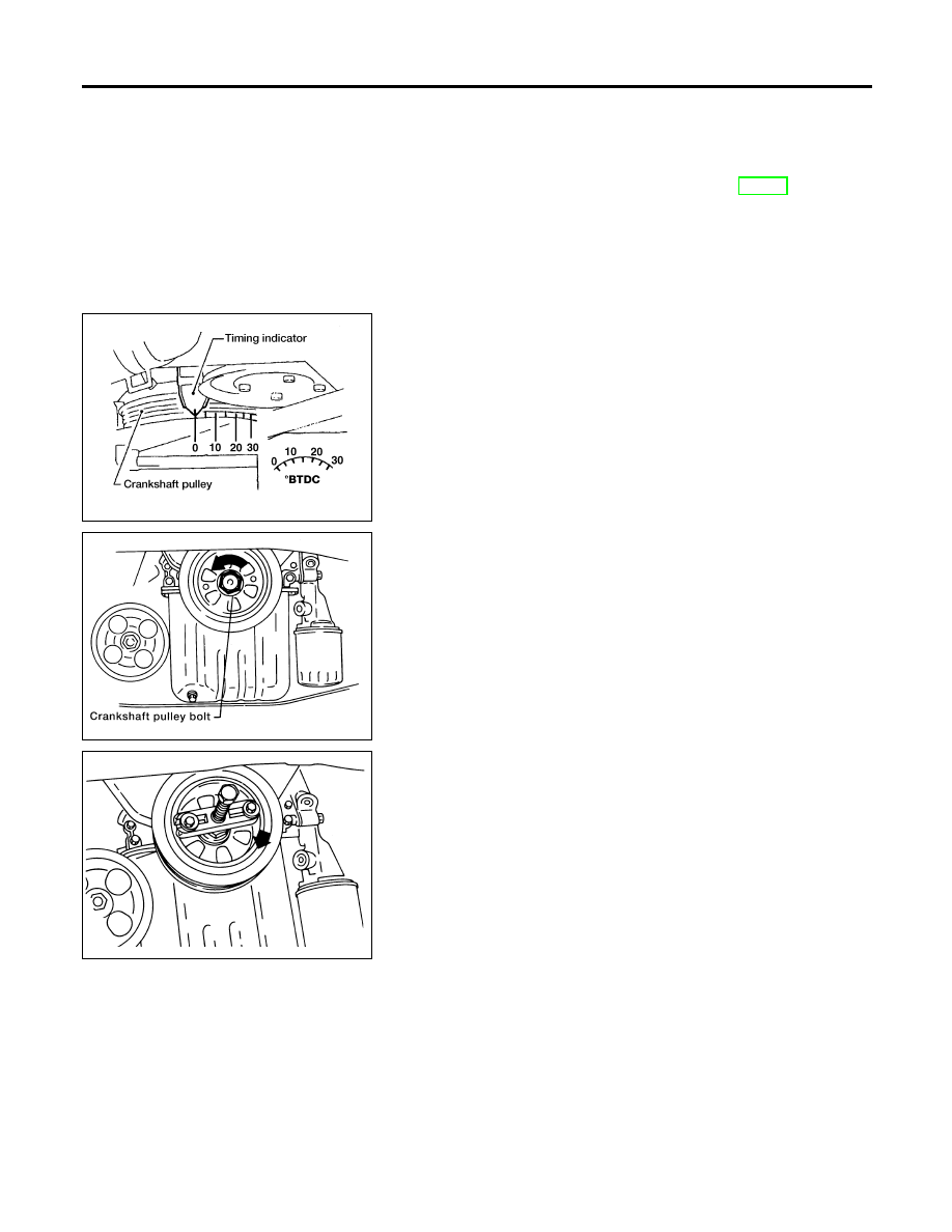
6.
Set No. 1 piston at TDC of its compression stroke.
AEM222
7.
Loosen crankshaft pulley bolt.
AEM007
8.
Remove crankshaft pulley using a suitable puller.
TIMING BELT
Removal
EM-18
AEM223
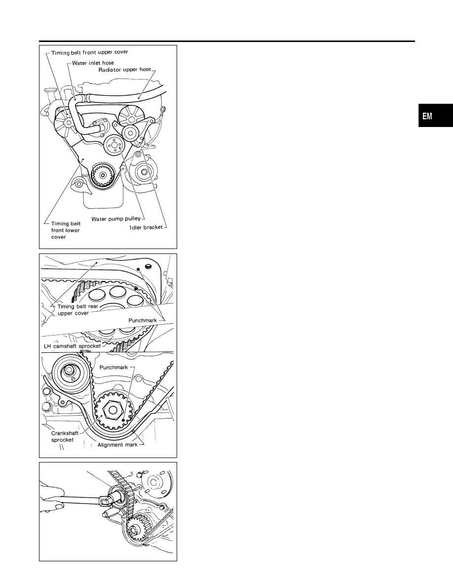
9.
Remove radiator upper hose and water inlet hose.
10. Remove compressor drive belt idler bracket.
11. Remove water pump pulley.
12. Remove breather pipe from timing belt front upper cover.
13. Remove timing belt front covers.
SEM394CA
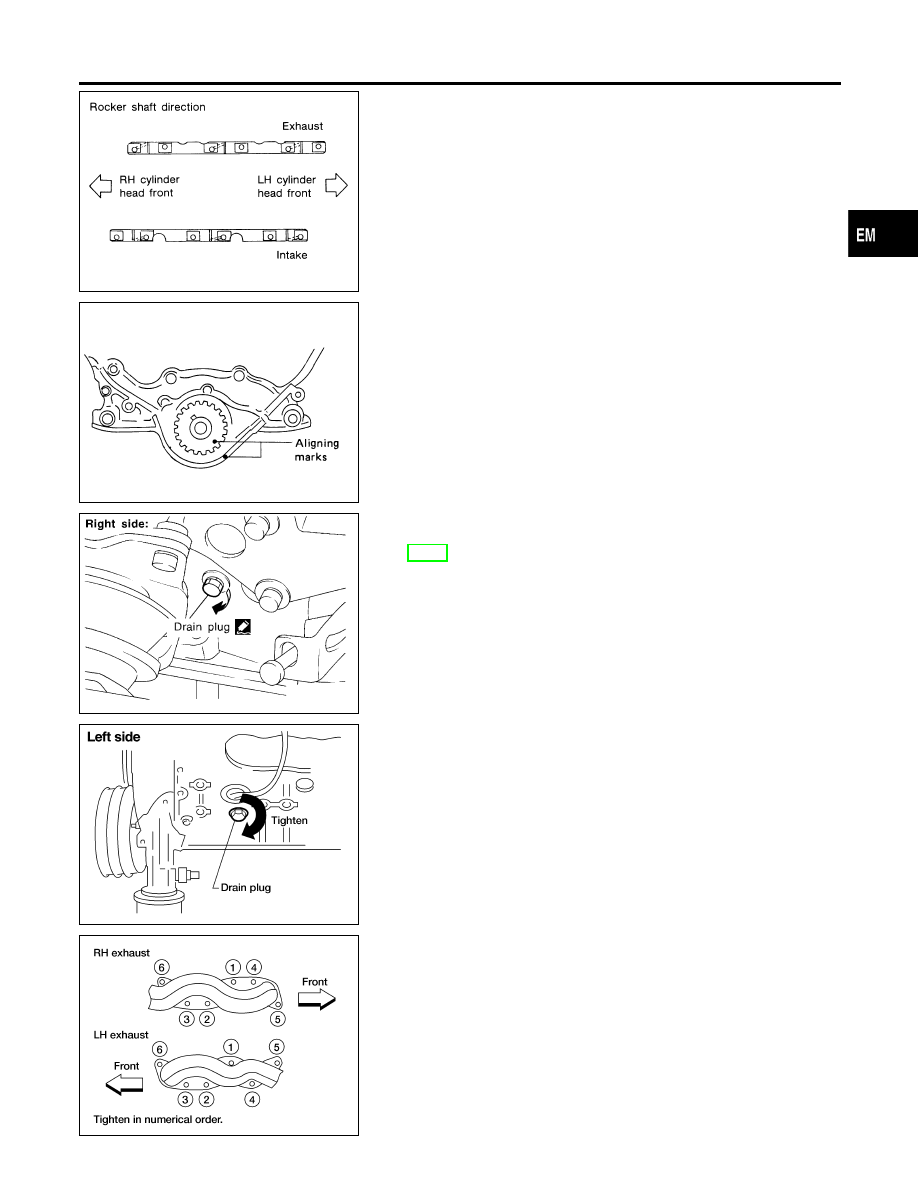
쐌
Align punchmark on LH camshaft sprocket with punch-
mark on timing belt rear cover.
쐌
Align punchmark on crankshaft sprocket with alignment
mark on oil pump housing.
쐌
Temporarily install crankshaft pulley bolt on crankshaft so
the crankshaft can be rotated.
SEM240A
14. Loosen timing belt tensioner nut, rotate tensioner, then remove
timing belt.
GI
MA
LC
EC
FE
AT
AX
SU
BR
ST
RS
BT
HA
SC
EL
IDX
TIMING BELT
Removal (Cont’d)
EM-19
Inspection
NDEM0011
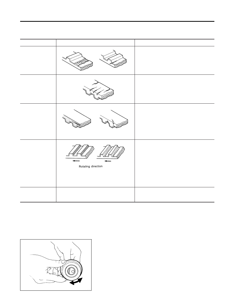
Visually check the condition of timing belt.
Replace if any abnormality is found.
Item to check
Problem
Cause
Tooth is broken/tooth
root is cracked.
SEM394A
쐌
Camshaft jamming
쐌
Distributor jamming
쐌
Damaged camshaft/crankshaft oil seal
Back surface is
cracked/worn.
SEM395A
쐌
Tensioner jamming
쐌
Overheated engine
쐌
Interference with belt cover
Side surface is worn.
SEM396A
쐌
Belt corners are worn and round.
쐌
Wicks are frayed and coming out.
쐌
Improper installation of belt
쐌
Malfunctioning crankshaft pulley plate/timing belt
plate
Teeth are worn.
SEM397A
쐌
Canvas on tooth face is worn down.
쐌
Canvas on tooth is fluffy, rubber layer is worn
down and faded white, or weft is worn down and
invisible.
쐌
Poor belt cover sealing
쐌
Coolant leakage at water pump
쐌
Camshaft not functioning properly
쐌
Distributor not functioning properly
쐌
Excessive belt tension
Oil/Coolant or water is
stuck to belt.
—
쐌
Poor oil sealing of each oil seal
쐌
Coolant leakage at water pump
쐌
Poor belt cover sealing
SEM558
BELT TENSIONER AND TENSIONER SPRING
NDEM0011S01
1.
Check belt tensioner for smooth turning.
2.
Check condition of tensioner spring.
TIMING BELT
Inspection
EM-20
SEM510EA
Installation
NDEM0012
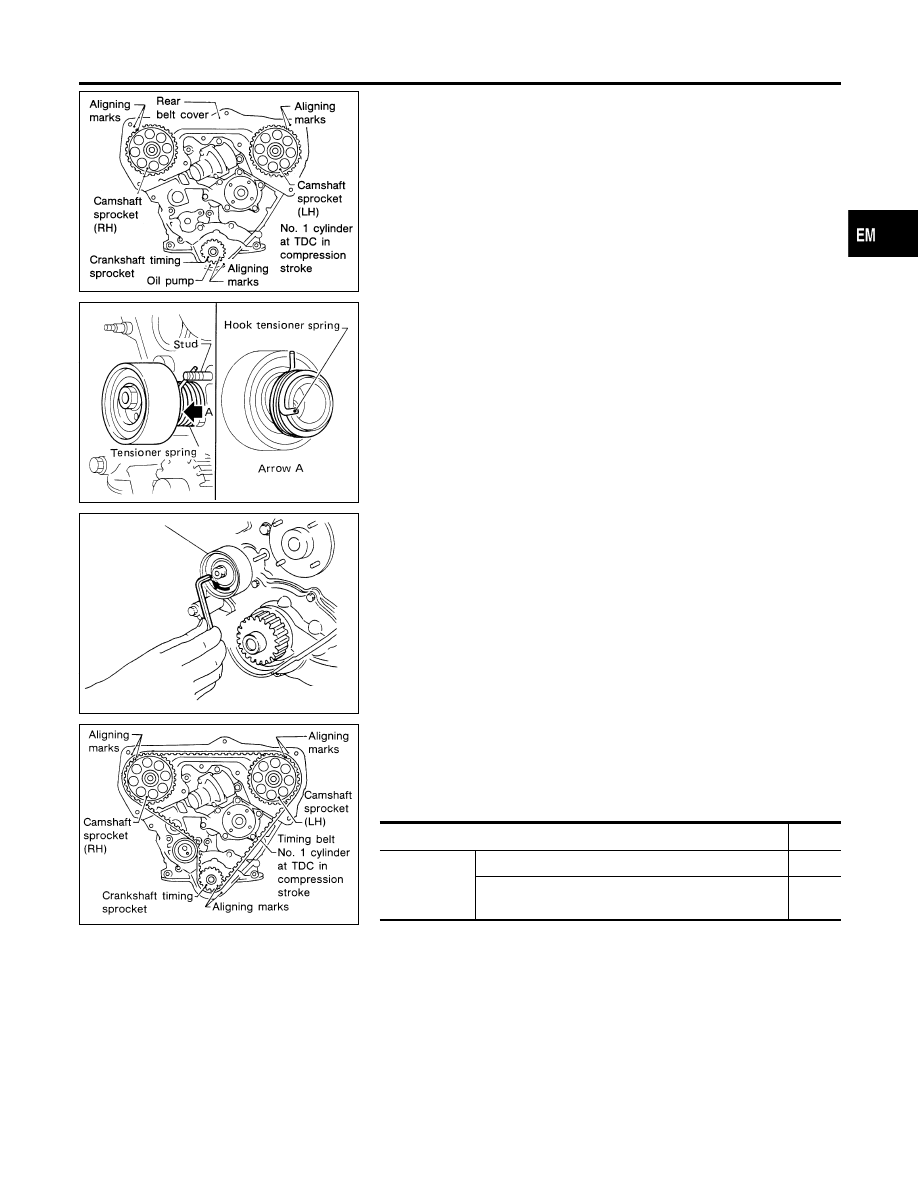
1.
Confirm that No. 1 piston is set at TDC on its compression
stroke.
SEM243A
2.
Install tensioner and tensioner spring.
Once stud is removed, apply locking sealant to threads of stud
on cylinder block side before installing.
SEM829A
3.
Turn tensioner fully outward with hexagon wrench, and tempo-
rarily tighten lock nut.
SEM511EA
4.
Set timing belt when engine is cold.
1)
Align white lines on timing belt with punchmarks on camshaft
sprockets and crankshaft sprocket.
2)
Point arrow on timing belt toward front belt cover.
Number of teeth (reference):
Number of timing belt teeth
133
Number of
teeth between
timing marks
Between LH and RH camshaft sprockets
40
Between LH camshaft sprocket and crankshaft tim-
ing sprocket
43
GI
MA
LC
EC
FE
AT
AX
SU
BR
ST
RS
BT
HA
SC
EL
IDX
TIMING BELT
Installation
EM-21
AEM418
AEM440
Tension Adjustment
NDEM0040
AFTER BELT REPLACEMENT
NDEM0040S01
If the timing belt was replaced (or to adjust tension on a used belt),
follow the steps below.
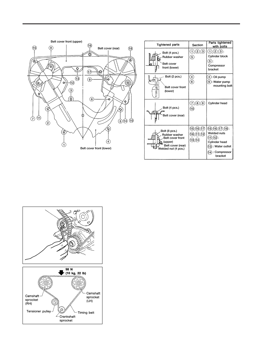
1.
Loosen tensioner lock nut, then turn tensioner clockwise and
counterclockwise with hexagon wrench at least 2 times.
SEM744DA
2.
Tighten tensioner lock nut.
3.
Turn crankshaft clockwise at least 2 times, then slowly set No.
1 piston at TDC on its compression stroke.
4.
Measure deflection of timing belt midway between camshaft
pulleys while pushing with 98 N (10 kg, 22 lb) force.
Belt deflection when engine is cold (Reference value):
13 - 15 mm (0.51 - 0.59 in)/98 N (10 kg, 22 lb)
5.
If NG, return to step 1.
TIMING BELT
Installation (Cont’d)
EM-22
AFTER ENGINE OVERHAUL OR ENGINE REASSEMBLY
(WITH ROCKER COVERS REMOVED)
NDEM0040S02
If the engine was overhauled or previously disassembled (i.e.
intake manifold and/or cylinder head were removed), follow the
steps below.
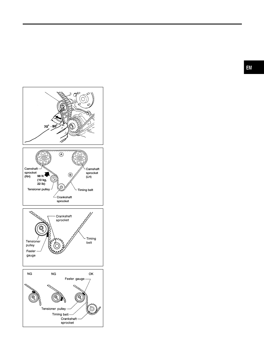
1.
Loosen rocker shaft bolts to relieve belt tension caused by the
cam shafts.
SEM886B
2.
Loosen tensioner lock nut, keeping tensioner steady with
hexagon wrench.
3.
Turn tensioner 70 to 80 degrees clockwise with hexagon
wrench to release belt tension, and temporarily tighten lock
nut.
4.
Turn crankshaft clockwise at least two times, then slowly set
No. 1 piston at TDC on its compression stroke.
AEM446
5.
Push middle of timing belt between RH camshaft sprocket and
tensioner pulley with force of 98 N (10 kg, 22 lb) to apply ten-
sions on part A and part B.
6.
Loosen tensioner lock nut, keeping tensioner steady with
hexagon wrench.
SEM240E
7.
Set feeler gauge as shown in figure which is 0.5 mm (0.0206
in) thick and 12.7 mm (0.500 in) wide.
SEM889BA
8.
Turn crankshaft clockwise until feeler gauge is positioned as
shown in figure.
쐌
Timing belt will move about 2.5 teeth.
9.
Tighten tensioner lock nut, keeping tensioner steady with
hexagon wrench.
10. Turn crankshaft clockwise or counterclockwise, and remove
feeler gauge.
11. Turn crankshaft clockwise at least two times, then slowly set
No. 1 piston at TDC on its compression stroke.
GI
MA
LC
EC
FE
AT
AX
SU
BR
ST
RS
BT
HA
SC
EL
IDX
TIMING BELT
Tension Adjustment (Cont’d)
EM-23
SEM744DA
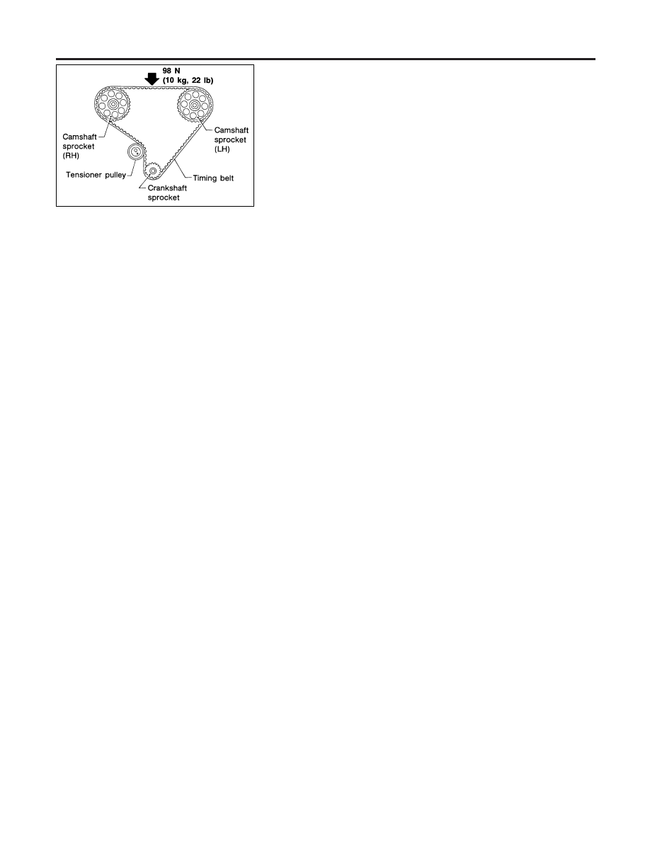
12. Measure deflection of timing belt midway between camshaft
pulleys while pushing with 98 N (10 kg, 22 lb) force.
Belt deflection when engine is cold (Reference value):
13 - 15 mm (0.51 - 0.59 in)/98 N (10 kg, 22 lb)
13. Install lower and upper belt covers.
TIMING BELT
Tension Adjustment (Cont’d)
EM-24
SEM257A
SEM285A
Replacement
NDEM0013
VALVE OIL SEAL
NDEM0013S01
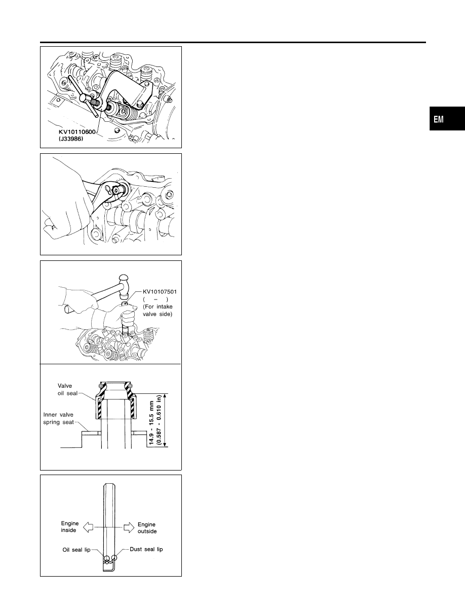
1.
Remove rocker cover.
2.
Remove rocker shaft assembly and valve lifters with valve lifter
guide.
3.
Remove valve springs and valve oil seal.
쐌
Piston concerned should be set at TDC to prevent valve from
falling.
쐌
When removing intake side valve oil seal, use Tool or suitable
tool.
쐌
When removing exhaust side valve oil seal, pull it out with
suitable tool.
SEM493F
4.
Apply engine oil to new valve oil seal and install it.
쐌
Before installing valve oil seal, install inner valve spring seat.
쐌
When installing intake side valve oil seal, use Tool.
쐌
When installing exhaust side valve oil seal, set it by hand.
SEM715A
OIL SEAL INSTALLING DIRECTION
NDEM0013S02
GI
MA
LC
EC
FE
AT
AX
SU
BR
ST
RS
BT
HA
SC
EL
IDX
OIL SEAL
Replacement
EM-25
SEM284A
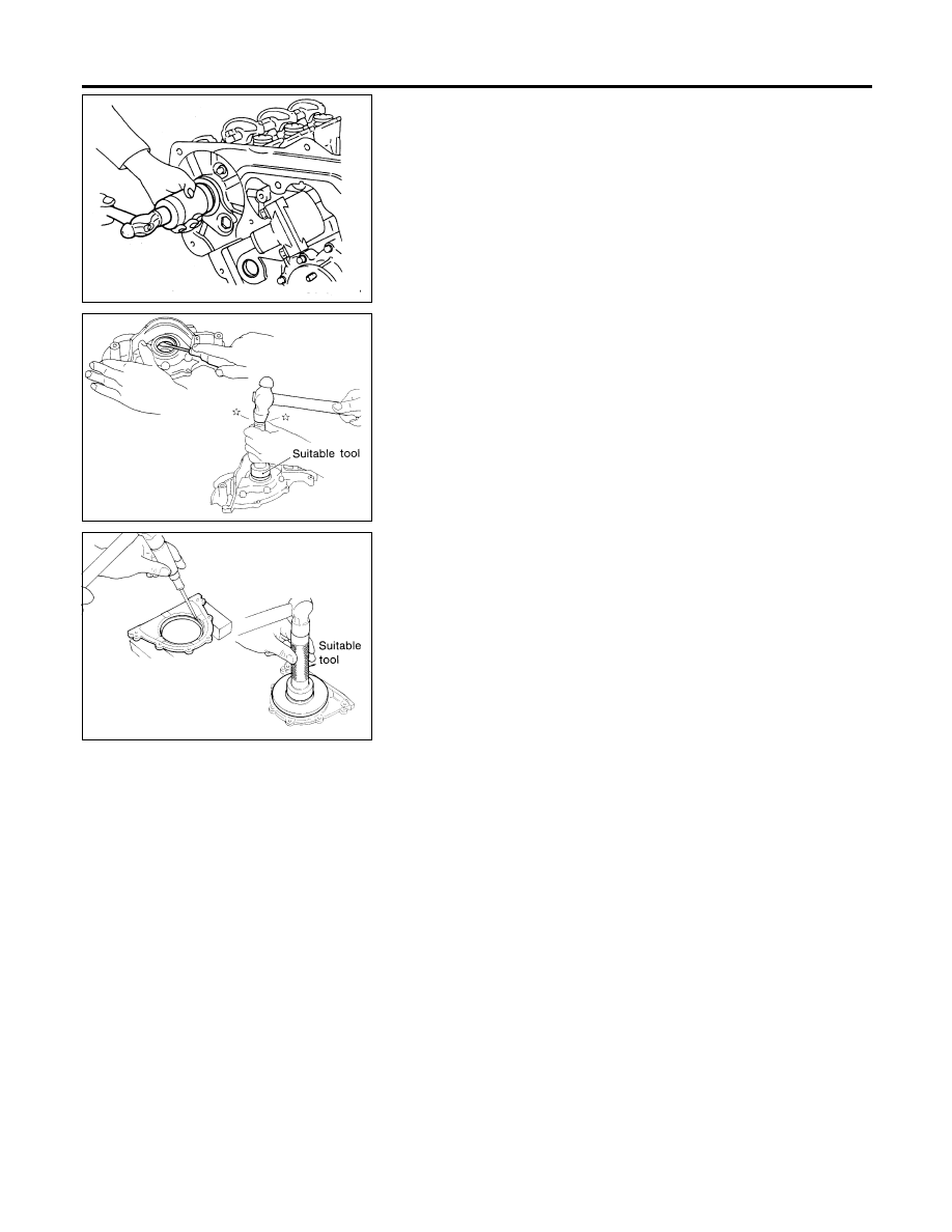
CAMSHAFT OIL SEAL
NDEM0013S03
1.
Remove timing belt.
2.
Remove camshaft sprocket.
3.
Remove camshaft.
4.
Remove camshaft oil seal.
Be careful not to scratch camshaft.
5.
Apply engine oil to new camshaft oil seal.
SEM241E
FRONT OIL SEAL
NDEM0013S04
1.
Remove timing belt and crankshaft sprocket.
2.
Remove oil pump assembly.
3.
Remove front oil seal from oil pump body.
4.
Apply engine oil to new oil seal and install it using suitable tool.
SEM242E
REAR OIL SEAL
NDEM0013S05
1.
Remove drive plate.
2.
Remove rear oil seal retainer.
3.
Remove rear oil seal from retainer.
쐌
Be careful not to scratch rear oil seal retainer.
4.
Apply engine oil to new oil seal and install it using suitable tool.
5.
Install rear oil seal retainer with a new gasket to cylinder block.
쐌
Always use a new oil seal retainer to cylinder block gasket.
OIL SEAL
Replacement (Cont’d)
EM-26
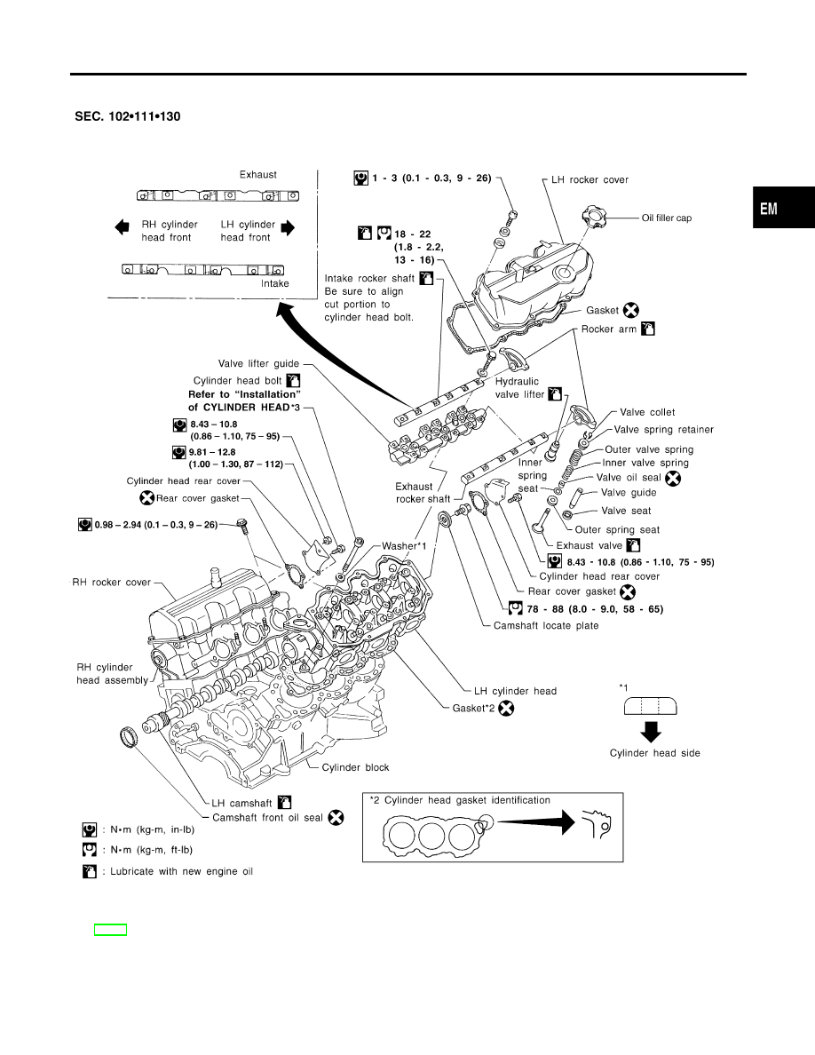
Components
NDEM0014
WEM145
*3
GI
MA
LC
EC
FE
AT
AX
SU
BR
ST
RS
BT
HA
SC
EL
IDX
CYLINDER HEAD
Components
EM-27
Removal
NDEM0015
1.
Release fuel pressure.
Refer to EC-35, “ Fuel Pressure Release”.
2.
Remove timing belt.
Refer to “Removal”, EM-18.
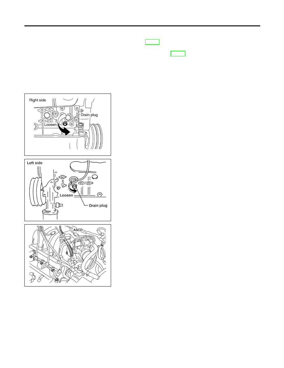
AEM417
AMA038
3.
Drain coolant by removing drain plugs from both sides of cyl-
inder block.
AEM453
4.
Disconnect air duct hose.
5.
Separate ASCD and accelerator control wire from intake mani-
fold collector.
6.
Remove intake manifold collector from engine. The following
parts should be disconnected to remove intake manifold col-
lector.
a.
Harness connectors for:
쐌
IACV-AAC valve
쐌
Throttle position sensor
쐌
Throttle position switch
쐌
Distributor (ignition coil)
쐌
Distributor
쐌
IACV-FICD solenoid valve
b.
Water hoses from collector
c.
Heater hoses
d.
PCV hose from RH/LH rocker cover
e.
Vacuum hoses for:
쐌
EVAP canister
쐌
Master brake cylinder
쐌
Pressure regulator
f.
Purge hose from purge control valve
CYLINDER HEAD
Removal
EM-28
g.
Spark plug wires
h.
Distributor assembly
i.
Three left/right bank injector connectors
j.
Ground harness
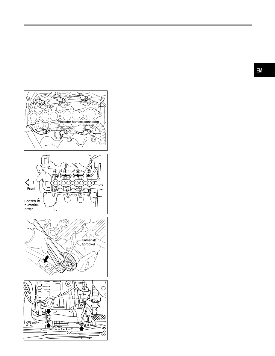
AEM452
7.
Remove fuel feed and fuel return hoses from injector fuel tube
assembly.
8.
Disconnect the right injector harness connectors.
9.
Remove injector fuel tube assembly.
SEM034E
10. Remove intake manifold from engine. The following parts
should be disconnected to remove intake manifold.
a.
Engine coolant temperature switch harness connector
b.
Water hose from thermostat housing
SEM819C
11. Remove both camshaft sprockets.
12. Remove rear timing belt cover.
13. Remove distributor.
After pulling out distributor from cylinder head, do not rotate
distributor rotor.
14. Remove harness clamp from RH rocker cover.
WEM101
15. Remove exhaust tube from LH exhaust manifold.
GI
MA
LC
EC
FE
AT
AX
SU
BR
ST
RS
BT
HA
SC
EL
IDX
CYLINDER HEAD
Removal (Cont’d)
EM-29
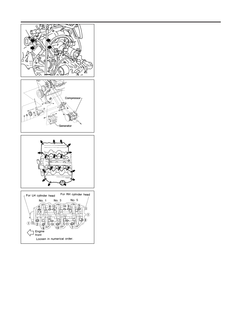
AEM074
16. Remove the nuts and bolt, then separate the LH exhaust mani-
fold from the RH exhaust manifold.
17. Remove the LH exhaust manifold to support bracket bolt.
AEM416
18. Remove compressor from bracket.
19. Remove generator from bracket.
20. Remove compressor and bracket.
SEM027E
21. Remove both rocker covers.
SEM926AA
22. Remove cylinder head with exhaust manifold.
쐌
A warped or cracked cylinder head could result from
removing in incorrect order.
쐌
Cylinder head bolts should be loosened in two or three
steps.
Disassembly
NDEM0016
CAUTION:
쐌
When installing sliding parts such as rocker arms, cam-
shaft and oil seal, be sure to apply new engine oil on their
sliding surfaces.
쐌
When tightening cylinder head bolts and rocker shaft
bolts, apply new engine oil to thread portions and seat
surfaces of bolts.
CYLINDER HEAD
Removal (Cont’d)
EM-30
SEM870BA
쐌
If hydraulic valve lifter is kept on its side, there is a risk of
air entering it. After removal, always set hydraulic valve
lifter straight up, or when laying it on its side, have it soak
in new engine oil.
쐌
Do not disassemble hydraulic valve lifter.
쐌
Attach tags to valve lifters so as not to mix them up.
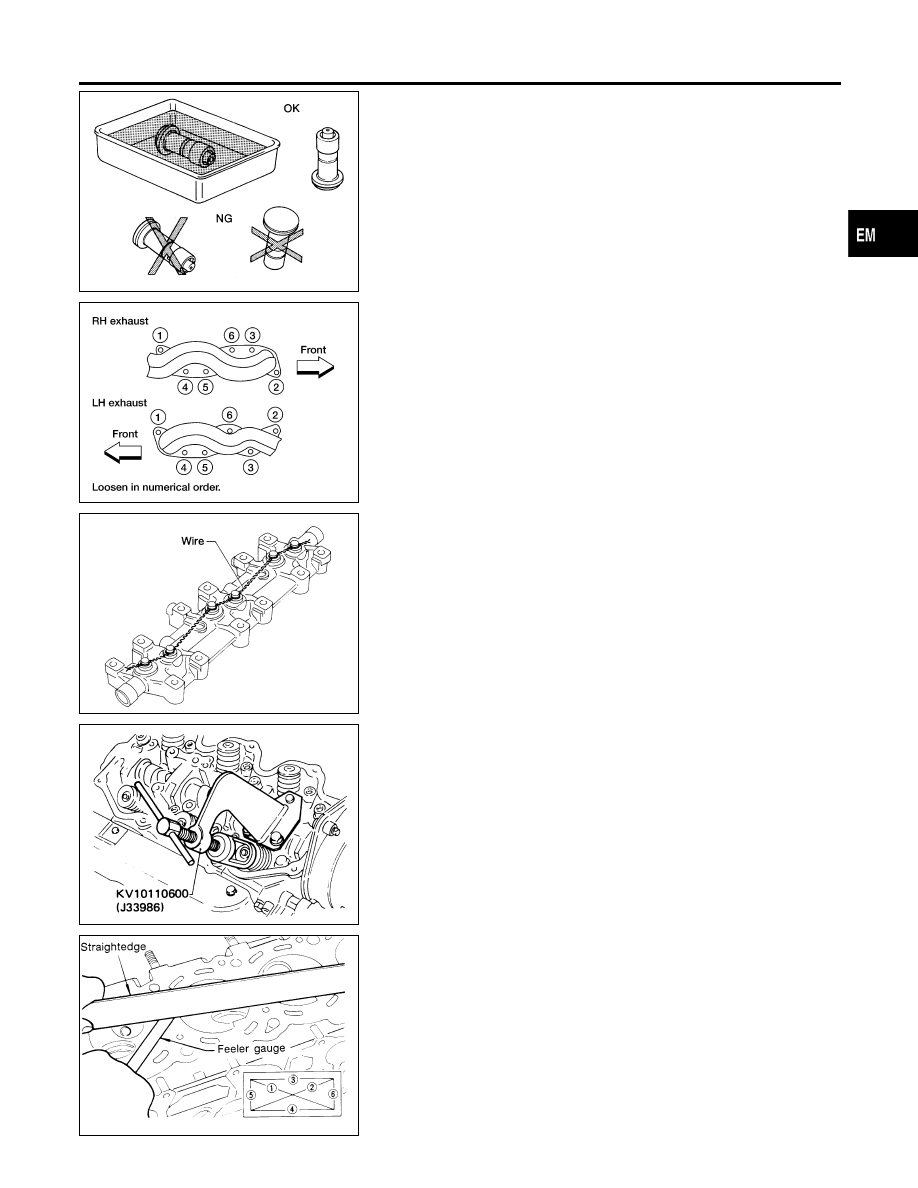
WEM102
1.
Remove exhaust manifolds from cylinder head.
SEM304A
2.
Remove rocker shafts with rocker arms.
Bolts should be loosened in two or three steps.
3.
Remove hydraulic valve lifters and lifter guide.
쐌
Hold hydraulic valve lifters with wire so that they will not
drop from lifter guide.
4.
Remove oil seal and camshaft.
쐌
Before removing camshaft, measure camshaft end play.
SEM257A
5.
Remove valve components with Tool.
6.
Remove valve oil seals with Tool or suitable tool.
SEM868A
Inspection
NDEM0017
CYLINDER HEAD DISTORTION
NDEM0017S01
Head surface flatness:
Less than 0.1 mm (0.004 in)
If beyond the specified limit, resurface it or replace it.
Resurfacing limit:
The resurfacing limit of cylinder head is determined by the
cylinder block resurfacing in an engine.
Amount of cylinder head resurfacing is “A”.
Amount of cylinder block resurfacing is “B”.
The maximum limit is as follows:
GI
MA
LC
EC
FE
AT
AX
SU
BR
ST
RS
BT
HA
SC
EL
IDX
CYLINDER HEAD
Disassembly (Cont’d)
EM-31
A + B = 0.2 mm (0.008 in)
After resurfacing cylinder head, check that camshaft rotates freely
by hand. If resistance is felt, cylinder head must be replaced.
Nominal cylinder head height:
106.8 - 107.2 mm (4.205 - 4.220 in)
CAMSHAFT VISUAL CHECK
NDEM0017S02
Check camshaft for scratches, seizure and wear.
SEM758A
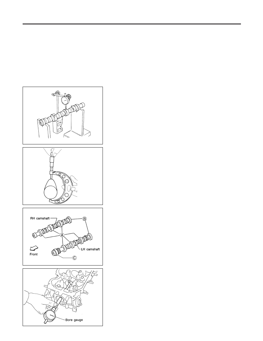
CAMSHAFT RUNOUT
NDEM0017S03
1.
Measure camshaft runout at the center journal.
Runout (Total indicator reading):
Limit 0.1 mm (0.004 in)
2.
If it exceeds the limit, replace camshaft.
SEM549A
CAMSHAFT CAM HEIGHT
NDEM0017S04
1.
Measure camshaft cam height.
Standard cam height:
Intake and exhaust:
38.943 - 39.133 mm (1.5332 - 1.5407 in)
Cam wear limit:
0.15 mm (0.0059 in)
2.
If wear is beyond the limit, replace camshaft.
SEM893BA
CAMSHAFT JOURNAL CLEARANCE
NDEM0017S05
SEM879A
1.
Measure inner diameter of camshaft bearing.
Standard inner diameter:
A 47.000 - 47.025 mm (1.8504 - 1.8514 in)
B 42.500 - 42.525 mm (1.6732 - 1.6742 in)
C 48.000 - 48.025 mm (1.8898 - 1.8907 in)
CYLINDER HEAD
Inspection (Cont’d)
EM-32
SEM012A
2.
Measure outer diameter of camshaft journal.
Standard outer diameter:
A 46.920 - 46.940 mm (1.8472 - 1.8480 in)
B 42.420 - 42.440 mm (1.6701 - 1.6709 in)
C 47.920 - 47.940 mm (1.8866 - 1.8874 in)
3.
If clearance exceeds the limit, replace camshaft and/or cylin-
der head.
Camshaft journal clearance limit:
0.15 mm (0.0059 in)
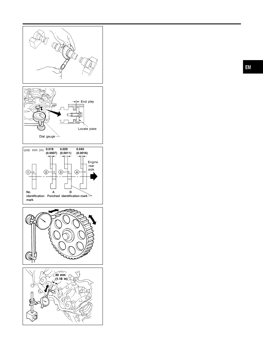
SEM392E
CAMSHAFT END PLAY
NDEM0017S06
1.
Install camshaft and locate plate in cylinder head.
2.
Measure camshaft end play.
Camshaft end play:
Standard:
0.03 - 0.06 mm (0.0012 - 0.0024 in)
WEM081
3.
If it is out of the specified range, select thickness of camshaft
locate plate to obtain standard specified end play.
Example:
When camshaft end play is 0.08 mm (0.0031 in) with camshaft
locate plate 1, replace camshaft locate plate 1 with camshaft
locate plate 4 to set the end play at 0.04 mm (0.0016 in).
SEM872B
CAMSHAFT SPROCKET RUNOUT
NDEM0017S07
1.
Install sprocket on camshaft.
2.
Measure camshaft sprocket runout.
Runout (Total indicator reading):
Limit:
0.1 mm (0.004 in)
3.
If it exceeds the limit, replace camshaft sprocket.
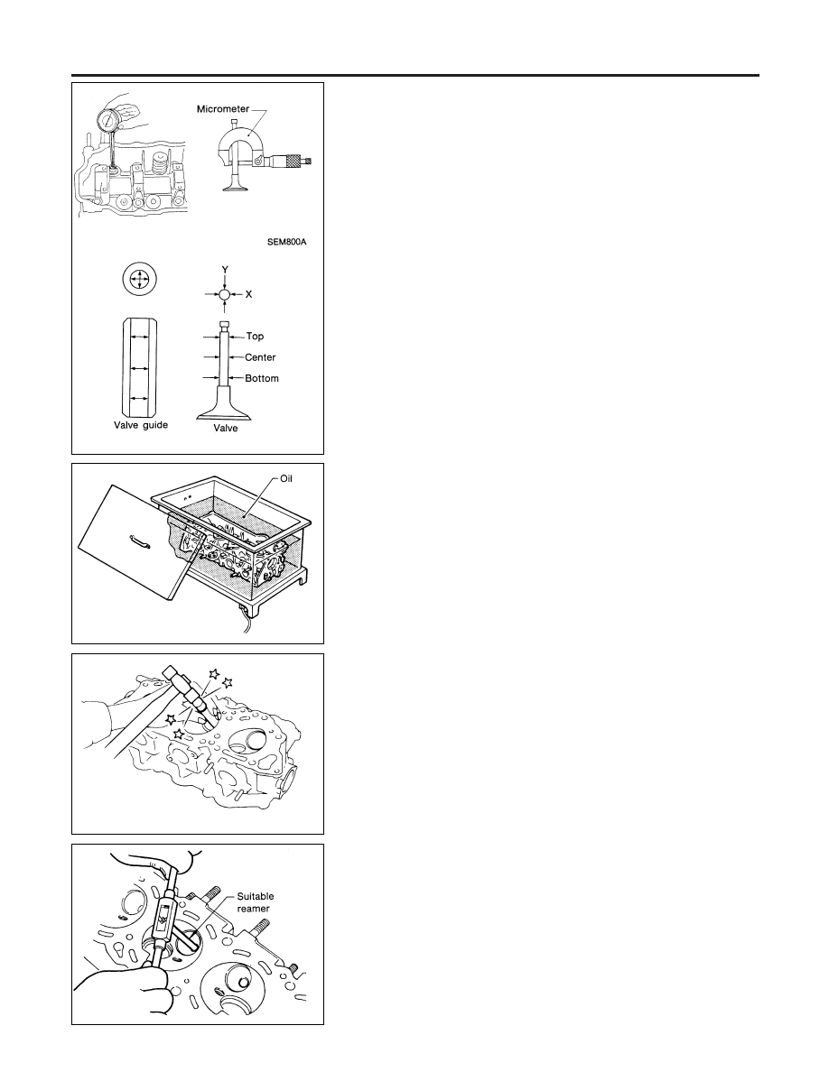
SEM263A
VALVE GUIDE CLEARANCE
NDEM0017S08
1.
Measure valve deflection in a right-angled direction with cam-
shaft. (Valve and valve guide mostly wear in this direction.)
Valve deflection limit (Dial gauge reading):
0.20 mm (0.0079 in)
GI
MA
LC
EC
FE
AT
AX
SU
BR
ST
RS
BT
HA
SC
EL
IDX
CYLINDER HEAD
Inspection (Cont’d)
EM-33
SEM751A
2.
If it exceeds the limit, check valve to valve guide clearance.
a.
Measure valve stem diameter and valve guide inner diameter.
b.
Check that clearance is within specification.
Valve to valve guide clearance:
Intake:
0.020 - 0.053 mm (0.0008 - 0.0021 in)
Exhaust:
0.030 - 0.049 mm (0.0012 - 0.0019 in)
Limit:
0.10 mm (0.0039 in)
c.
If it exceeds the limit, replace valve or valve guide.
SEM008A
VALVE GUIDE REPLACEMENT
NDEM0017S09
1.
To remove valve guide, heat cylinder head to 150 to 160°C
(302 to 320°F) by soaking in heated oil.
SEM264A
2.
Drive out valve guide with a press [under a 20 kN (2 ton, 2.2
US ton, 2.0 Imp ton) pressure] or hammer and suitable tool.
SEM088C
3.
Ream cylinder head valve guide hole.
Valve guide hole diameter (for service parts):
Intake:
11.175 - 11.196 mm (0.4400 - 0.4408 in)
Exhaust:
12.175 - 12.196 mm (0.4793 - 0.4802 in)
CYLINDER HEAD
Inspection (Cont’d)
EM-34
SEM089C
4.
Heat cylinder head to 150 to 160°C (302 to 320°F) by soaking
in heated oil and press service valve guide onto cylinder head.
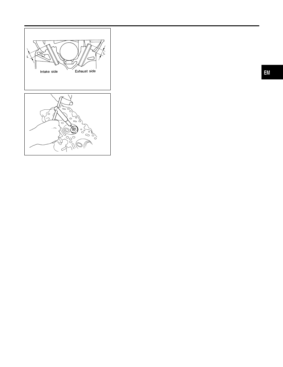
Projection “L”:
13.2 - 13.4 mm (0.520 - 0.528 in)
5.
Ream valve guide.
Finished size:
Intake:
7.000 - 7.018 mm (0.2756 - 0.2763 in)
Exhaust:
8.000 - 8.011 mm (0.3150 - 0.3154 in)
SEM090C
VALVE SEATS
NDEM0017S10
Check valve seats for any evidence of pitting at valve contact
surface, and reseat or replace if it has worn out excessively.
쐌
Before repairing valve seats, check valve and valve guide
for wear. If they have worn, replace them. Then correct
valve seat.
쐌
Use both hands to cut uniformly.
GI
MA
LC
EC
FE
AT
AX
SU
BR
ST
RS
BT
HA
SC
EL
IDX
CYLINDER HEAD
Inspection (Cont’d)
EM-35
SEM795A
REPLACING VALVE SEAT FOR SERVICE PARTS
=NDEM0017S11
1.
Bore out old seat until it collapses. The machine depth stop
should be set so that boring cannot continue beyond the bot-
tom face of the seat recess in cylinder head.
2.
Ream cylinder head recess.
Reaming bore for service valve seat:
Oversize [0.5 mm (0.020 in)]:
Intake:
44.500 - 44.516 mm (1.7520 - 1.7526 in)
Exhaust:
37.500 - 37.516 mm (1.4764 - 1.4770 in)
Reaming should be done in circles concentric to the valve
guide center so that valve seat will have the correct fit.
3.
Heat cylinder head to 150 to 160°C (302 to 320°F) by soaking
in heated oil.
4.
Press fit valve seat until it seats on the bottom.
SEM892B
5.
Cut or grind valve seat using suitable tool at the specified
dimensions. Refer to “Valve”, EM-60.
6.
After cutting, lap valve seat with abrasive compound.
7.
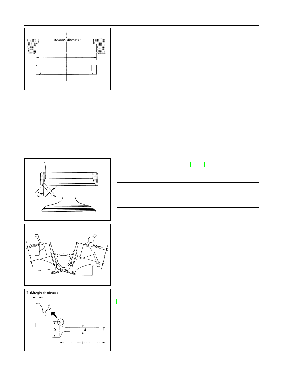
Check valve seating condition.
Intake
Exhaust
Seat face angle “
α
”
degree
45
45
Contacting width “W”
mm (in)
1.75 (0.0689)
1.7 (0.067)
SEM621F
8.
Use a depth gauge to measure the distance between the
mounting surface of the cylinder head spring seat and the
valve stem end. If the distance is shorter than specified, repeat
step 5 above to adjust it. If it is longer, replace the valve seat
with a new one.
Intake:
44.7 - 44.9 mm (1.760 - 1.768 in)
Exhaust:
45.4 - 45.6 mm (1.787 - 1.795 in)
SEM188A
VALVE DIMENSIONS
NDEM0017S12
Check dimensions in each valve. For dimensions, refer to “Valve”,
EM-60.
When valve head has been worn down to 0.5 mm (0.020 in) in
margin thickness, replace valve.
Grinding allowance for valve stem tip is 0.2 mm (0.008 in) or
less.
CYLINDER HEAD
Inspection (Cont’d)
EM-36
SEM207E
VALVE SPRING
NDEM0017S13
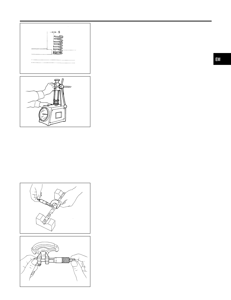
Squareness
NDEM0017S1301
1.
Measure “S” dimension.
Out-of-square:
Outer:
Less than 2.2 mm (0.087 in)
Inner:
Less than 1.9 mm (0.075 in)
2.
If not within specification, replace spring.
EM113
Pressure
NDEM0017S1302
Check valve spring pressure.
Standard pressure: N (kg, lb) at height mm (in)
Outer:
523.7 (53.4, 117.7) at 30.0 (1.181)
Inner:
255.0 (26.0, 57.3) at 25.0 (0.984)
Limit pressure: N (kg, lb) at height mm (in)
Outer:
More than 228.5 (23.3, 51.4) at 25.0 (0.984)
Inner:
More than 225.6 (23.0, 50.7) at 25.0 (0.984)
If not within specification, replace spring.
SEM761A
ROCKER SHAFT AND ROCKER ARM
NDEM0017S14
1.
Check rocker shafts for scratches, seizure and wear.
2.
Check outer diameter of rocker shaft.
Diameter:
17.979 - 18.000 mm (0.7078 - 0.7087 in)
SEM762A
3.
Check inner diameter of rocker arm.
Diameter:
18.007 - 18.028 mm (0.7089 - 0.7098 in)
Rocker arm to shaft clearance:
0.007 - 0.049 mm (0.0003 - 0.0019 in)
쐌
Keep rocker arm with hydraulic valve lifter standing to
prevent air from entering hydraulic valve lifter when
checking.
GI
MA
LC
EC
FE
AT
AX
SU
BR
ST
RS
BT
HA
SC
EL
IDX
CYLINDER HEAD
Inspection (Cont’d)
EM-37
SEM243E
HYDRAULIC VALVE LIFTER
NDEM0017S15
1.
Check contact and sliding surfaces for wear or scratches.
2.
Check diameter of valve lifter.
Outer diameter:
15.947 - 15.957 mm (0.6278 - 0.6282 in)
SEM760A
3.
Check valve lifter guide inner diameter.
Inner diameter:
16.000 - 16.013 mm (0.6299 - 0.6304 in)
Standard clearance between valve lifter and lifter
guide:
0.043 - 0.066 mm (0.0017 - 0.0026 in)
SEM638B
Assembly
NDEM0018
1.
Install valve component parts.
쐌
Always use new valve oil seal. Refer to “VALVE OIL
SEAL”, EM-25.
쐌
Before installing valve oil seal, install inner valve spring
seat.
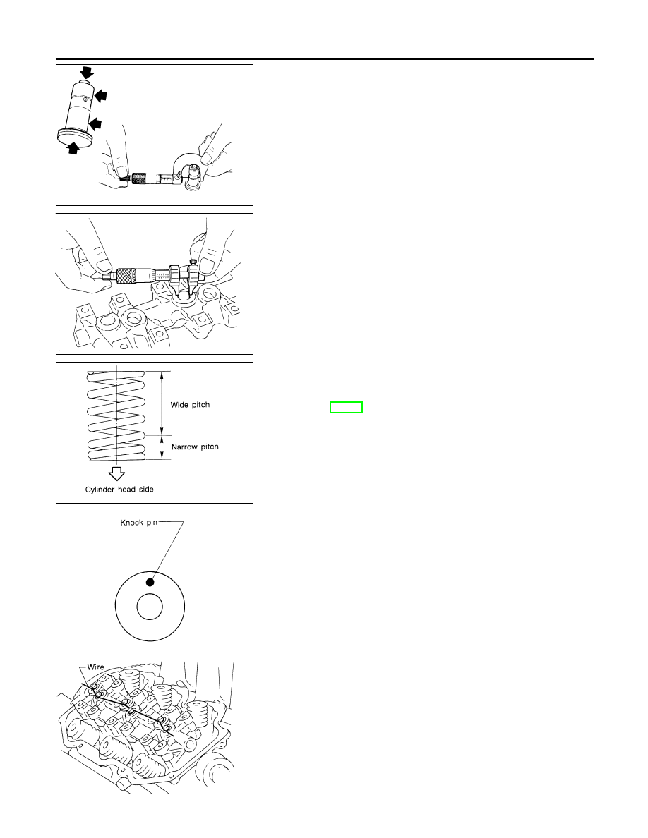
쐌
Install outer valve spring (uneven pitch type) with its nar-
row pitch side toward cylinder head side.
쐌
After installing valve component parts, use plastic ham-
mer to lightly tap valve stem tip to assure a proper fit.
SEM834B
2.
Install camshafts, locate plates and cylinder head rear covers.
쐌
Set knock pin of camshaft at the top.
SEM280A
3.
Install valve lifters into valve lifter guide.
쐌
Assemble valve lifters to their original position and hold
all valve lifters with wire to prevent lifters from falling off.
쐌
After installing, remove the wire.
CYLINDER HEAD
Inspection (Cont’d)
EM-38
SEM835BA
4.
Install rocker shafts with rocker arms.
쐌
Tighten bolts gradually in two or three stages.
쐌
Before tightening, be sure to set camshaft lobe at the posi-
tion where lobe is not lifted.
a.
Set No. 1 piston at TDC on its compression stroke and tighten
rocker shaft bolts for No. 2, No. 4 and No. 6 cylinders.
b.
Set No. 4 piston at TDC on its compression stroke and tighten
rocker shaft bolts for No. 1, No. 3 and No. 5 cylinders.
5.
Install exhaust manifold to cylinder head in reverse order of
removal.
SEM836B
Installation
NDEM0019
1.
Set No. 1 piston at TDC on its compression stroke as follows:
a.
Align crankshaft sprocket aligning mark with mark on oil pump
body.
b.
Confirm that knock pin on camshaft is set at the top.
SEM861CA
AEM454
2.
Install both drain plugs.
쐌
Use Genuine RTV Silicone Sealant or equivalent. Refer to
GI-48, “Recommended Chemical Products and Sealants”.
AEM414
3.
Install exhaust manifolds to cylinder head.
GI
MA
LC
EC
FE
AT
AX
SU
BR
ST
RS
BT
HA
SC
EL
IDX
CYLINDER HEAD
Assembly (Cont’d)
EM-39
SEM877A
4.
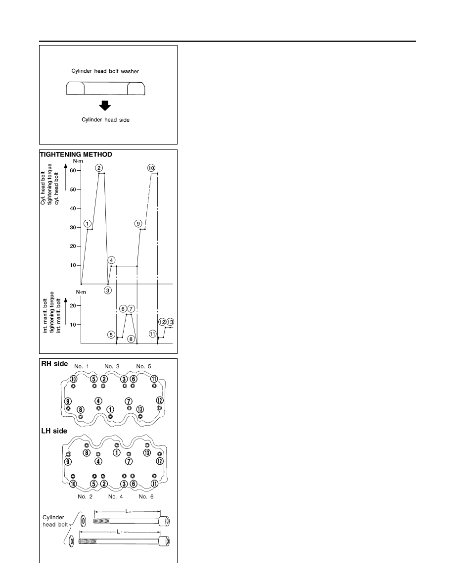
Install cylinder head with new gasket.
쐌
Be sure to install washers between bolts and cylinder
head.
쐌
Do not rotate crankshaft and camshaft separately, or
valves will hit piston heads.
WEM014
SEM348F
5.
Tighten cylinder head bolts in numerical order using angle
wrench [ST10120000 (J24239-01)].
Apply engine oil to threads and seating surfaces of cylinder
head bolts before installing them.
쐌
Cylinder head bolts for 4, 7, 9 and 12 are longer than the
others.
L
1
: 127 mm (5.00 in) for 4, 7, 9 and 12
L
2
: 106 mm (4.17 in) for others
쐌
Install intake manifold and cylinder head at the same time
using the following procedure:
1)
Tighten cylinder head bolts to 29 N·m (3.0 kg-m, 22 ft-lb).
2)
Tighten cylinder head bolts to 59 N·m (6.0 kg-m, 43 ft-lb).
3)
Loosen cylinder head bolts completely.
4)
Tighten cylinder head bolts to 10 N·m (1.0 kg-m, 7 ft-lb).
5)
Tighten intake manifold bolts and nuts to 4 N·m (0.4 kg-m, 2.9
ft-lb).
6)
Tighten intake manifold bolts and nuts to 18 N·m (1.8 kg-m, 13
ft-lb).
7)
Tighten intake manifold bolts and nuts to 16 to 20 N·m (1.6 to
2.0 kg-m, 12 to 14 ft-lb).
8)
Loosen intake manifold bolts and nuts completely.
9)
Tighten cylinder head bolts to 29 N·m (3.0 kg-m, 2.2 ft-lb).
10) Turn cylinder head bolts to 60 to 65 degrees clockwise. If an
angle wrench is not available, tighten cylinder head bolts to 54
to 64 N·m (5.5 to 6.5 kg-m, 40 to 47 ft-lb).
11) Tighten cylinder head sub-bolts to 9.0 to 11.8 N·m (0.92 to 1.20
kg-m, 6.7 to 8.7 ft-lb).
12) Tighten intake manifold bolts and nuts to 4 N·m (0.4 kg-m, 2.9
ft-lb).
13) Tighten intake manifold bolts and nuts to 9 N·m (0.9 kg-m, 6.5
ft-lb).
14) Tighten intake manifold bolts and nuts to 8 to 10 N·m (0.8 to
1.0 kg-m, 5.8 to 7 ft-lb).
CYLINDER HEAD
Installation (Cont’d)
EM-40
SEM825C
쐌
If only intake manifold is removed and to be used again,
install it using the following procedure:
1)
Tighten all bolts and nuts to 4 N·m (0.4 kg-m, 2.9 ft-lb).
2)
Tighten all bolts and nuts to 9 N·m (0.9 kg-m, 6.5 ft-lb).
3)
Tighten all bolts and nuts to 8 to 10 N·m (0.8 to 1.0 kg-m, 5.8
to 7 ft-lb).
CAUTION:
If replacing intake manifold with a new one, cylinder head
gasket must also be replaced with a new one. Refer to step 4.
SEM403C
6.
Install both rocker covers.
AEM416
7.
Install compressor and generator bracket.
8.
Install generator.
9.
Install compressor.
10. Install exhaust front tube to exhaust manifold.
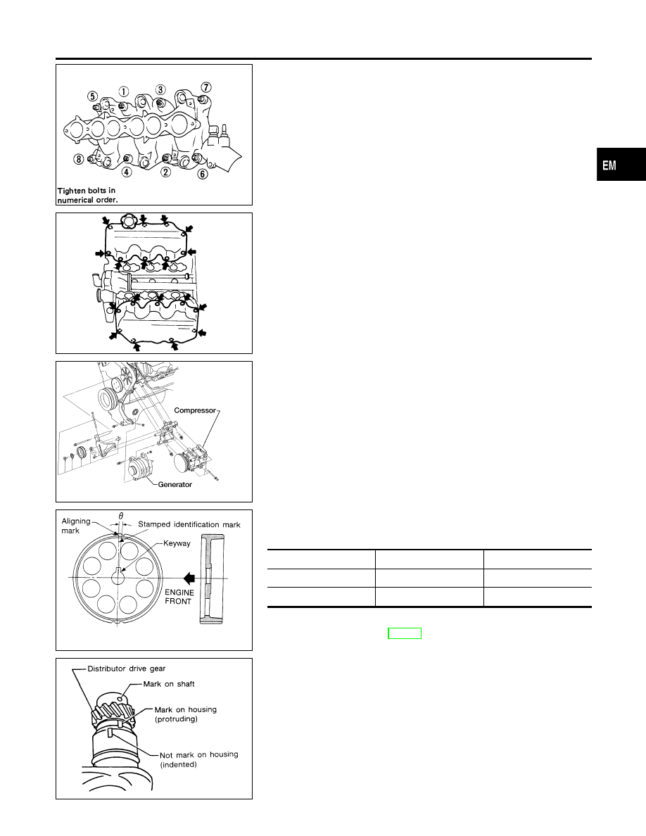
SEM303A
11. Install rear belt cover and camshaft sprocket.
쐌
RH camshaft sprocket and LH camshaft sprocket are dif-
ferent parts. Be sure to install them in the correct location.
Identification mark
θ
RH camshaft sprocket
R3
0°53
′
LH camshaft sprocket
L3
−3°27
′
12. Install timing belt and adjust belt tension.
Refer to “Installation”, EM-21.
SEM837BA
13. Install distributor.
1)
Align mark on shaft with protruding mark on housing.
GI
MA
LC
EC
FE
AT
AX
SU
BR
ST
RS
BT
HA
SC
EL
IDX
CYLINDER HEAD
Installation (Cont’d)
EM-41
AEM048
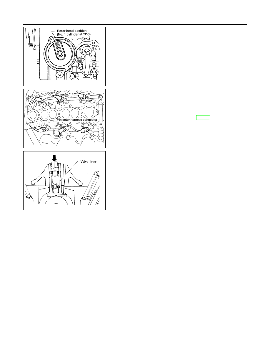
2)
After installing, confirm that distributor rotor head is set as
shown in figure.
AEM452
14. Install injector fuel tube assembly.
15. Connect all injector harness connectors.
16. Install fuel feed and fuel return hoses to injector fuel tube
assembly.
17. Install intake manifold collector. Install all parts which were
removed in step 6 under “Removal”, EM-28.
18. Install ASCD and accelerator control wire.
SEM531A
19. Check hydraulic valve lifter.
a.
Push plunger forcefully with your finger.
쐌
Be sure to check it with rocker arm in its free position (not
on the lobe).
b.
If valve lifter moves more than 1 mm (0.04 in), air may be
inside it.
c.
Bleed air off by running engine at 1,000 rpm under no load for
about 10 minutes.
d.
If hydraulic valve lifters are still noisy, replace them and bleed
air off again in the same manner as in step 19 (c).
CYLINDER HEAD
Installation (Cont’d)
EM-42

Removal and Installation
NDEM0020
WARNING:
쐌
Situate vehicle on a flat and solid surface.
쐌
Place chocks at front and back of rear wheels.
쐌
Do not remove engine until exhaust system has com-
pletely cooled off. Otherwise, you may burn yourself
and/or fire may break out in fuel line.
쐌
For safety during subsequent steps, the tension of wires
should be slackened against the engine.
쐌
Before disconnecting fuel hose, release fuel pressure
from fuel line.
Refer to EC-35, “Fuel Pressure Release”.
쐌
Before removing front axle from transmission, place
safety stands under designated front supporting points.
Refer to GI-43, “LIFTING POINTS AND TOW TRUCK TOW-
ING.
쐌
Be sure to hoist engine and transmission in a safe man-
ner.
쐌
For engines not equipped with engine slingers, attach
proper slingers and bolts described in PARTS CATALOG.
CAUTION:
쐌
When lifting engine, be careful not to strike adjacent parts,
especially accelerator wire casing, brake lines, and brake
master cylinder.
쐌
In hoisting the engine, always use engine slingers in a
safe manner.
쐌
Before separating engine and transmission, remove
crankshaft position sensor (OBD) from the assembly.
쐌
Always take extra care not to damage edge of crankshaft
position sensor (OBD), or ring gear teeth.
쐌
Do not loosen front engine mounting insulator cover
securing bolts.
When cover is removed, damper oil flows out and mount-
ing insulator will not function.
GI
MA
LC
EC
FE
AT
AX
SU
BR
ST
RS
BT
HA
SC
EL
IDX
ENGINE ASSEMBLY
Removal and Installation
EM-43
ENGINE MOUNTING
NDEM0020S01
WEM131
ENGINE ASSEMBLY
Removal and Installation (Cont’d)
EM-44
1.
Remove front wheels, engine under covers and side cover.
2.
Drain coolant from cylinder block and radiator. Refer to MA-14,
“Changing Engine Coolant”.
3.
Remove vacuum hoses, fuel tubes, wires, harnesses and con-
nectors.
4.
Remove exhaust tube, ball joints and drive shafts.
5.
Remove drive belts.
6.
Discharge refrigerant, refer to HA-122, “ HFC-134a (R-134a) Ser-
vice Procedures”.
7.
Remove A/C compressor manifold.
8.
Remove power steering oil pump from engine.
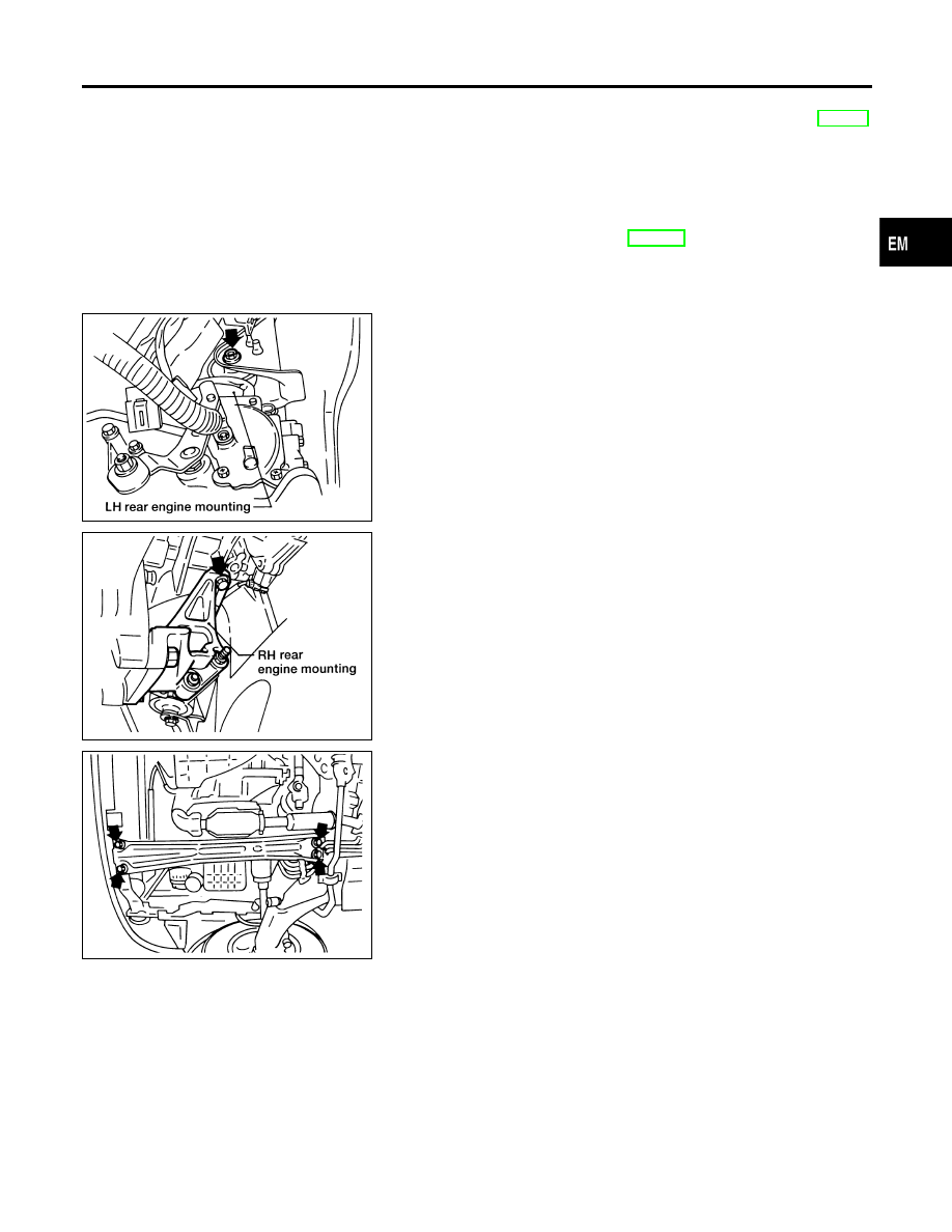
AEM011
9.
Set a powertrain lift under engine and transaxle.
10. Remove LH rear engine mounting bolts.
AEM012
11. Remove RH rear engine mounting.
12. If equipped, remove the rear A/C refrigerant lines support
bracket bolts.
AEM070
13. Remove center member bolts, then slowly lower powertrain lift.
GI
MA
LC
EC
FE
AT
AX
SU
BR
ST
RS
BT
HA
SC
EL
IDX
ENGINE ASSEMBLY
Removal and Installation (Cont’d)
EM-45

14. Remove engine with transaxle as shown.
AEM415
ENGINE ASSEMBLY
Removal and Installation (Cont’d)
EM-46
Components
NDEM0021
WEM128
GI
MA
LC
EC
FE
AT
AX
SU
BR
ST
RS
BT
HA
SC
EL
IDX
CYLINDER BLOCK
Components
EM-47
Removal and Installation
NDEM0022
CAUTION:
쐌
When installing sliding parts such as bearings and
pistons, be sure to apply engine oil on the sliding sur-
faces.
쐌
Place removed parts such as bearings and bearing caps
in their proper order and direction.
쐌
When installing connecting rod bolts and main bearing
cap bolts, apply new engine oil to threads and seating
surfaces.
쐌
Do not allow any magnetic materials to contact the ring
gear teeth on drive plate and rear plate.
SEM326FA
Disassembly
NDEM0023
PISTON AND CRANKSHAFT
NDEM0023S01
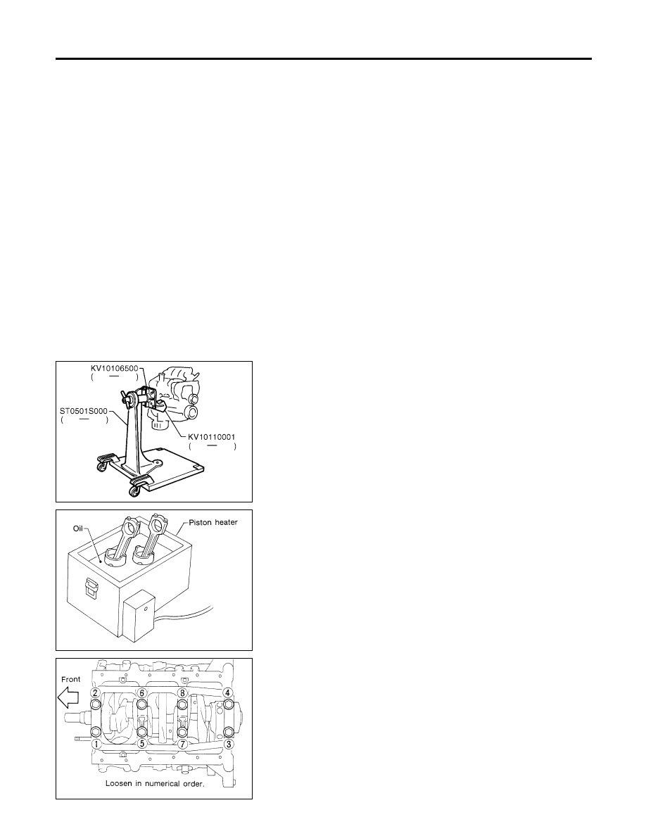
1.
Place engine on a work stand.
2.
Drain coolant and oil.
3.
Remove timing belt.
4.
Remove oil pan and oil pump.
5.
Remove water pump.
6.
Remove cylinder head.
SEM877B
7.
Remove pistons with connecting rods.
쐌
When disassembling piston and connecting rod, remove snap
ring first, then heat piston to 60 to 70°C (140 to 158°F) or use
piston pin press stand at room temperature.
CAUTION:
쐌
When piston rings are not replaced, make sure that piston
rings are mounted in their original positions.
쐌
When replacing piston rings, if there is no punchmark,
install with either side up.
SEM551E
8.
Remove bearing cap and crankshaft.
쐌
Before removing bearing cap, measure crankshaft end
play.
쐌
Bolts should be loosened in two or three steps.
CYLINDER BLOCK
Removal and Installation
EM-48
SEM684E
Inspection
NDEM0024
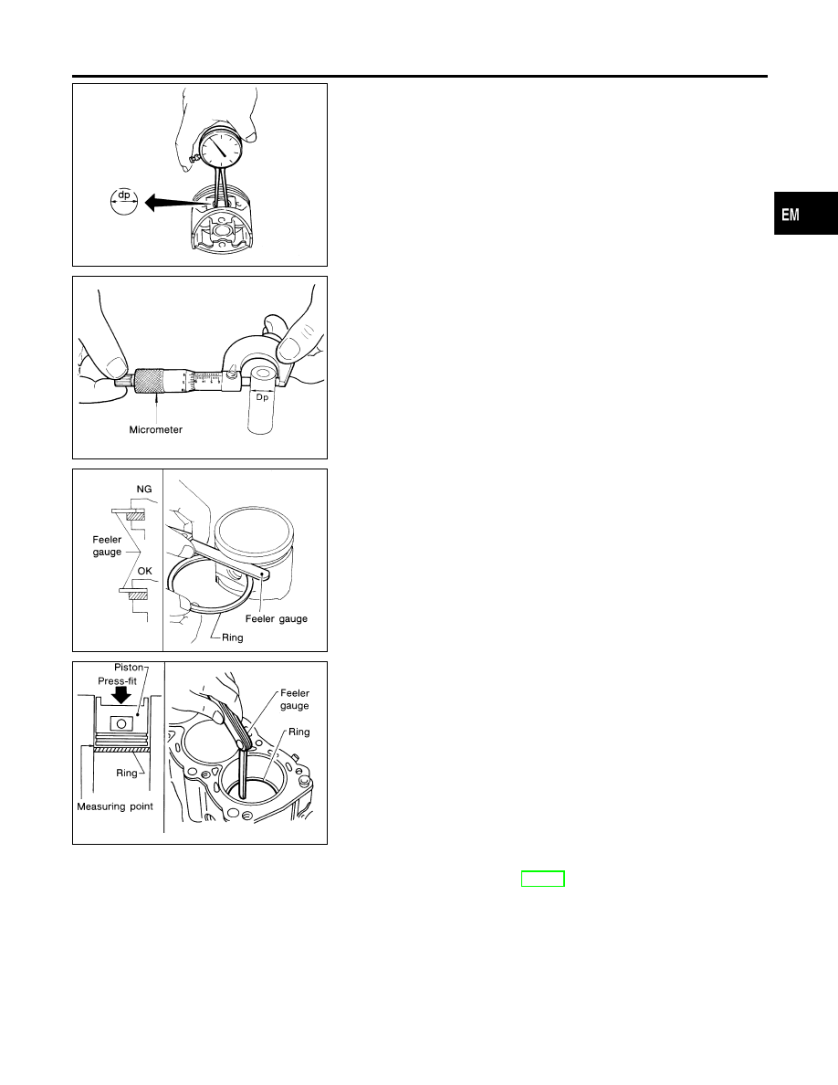
PISTON AND PISTON PIN CLEARANCE
NDEM0024S01
1.
Measure inner diameter of piston pin hole “dp”.
Standard diameter “dp”:
20.969 - 20.981 mm (0.8255 - 0.8260 in)
AEM024
2.
Measure outer diameter of piston pin “Dp”.
Standard diameter “Dp”:
20.971 - 20.983 mm (0.8256 - 0.8261 in)
3.
Calculate piston pin clearance.
dp − Dp = 0 to -0.004 mm (0 to -0.0002 in)
If it exceeds the above value, replace piston assembly with pin.
SEM024AA
PISTON RING SIDE CLEARANCE
NDEM0024S02
Side clearance:
Top ring: 0.040 - 0.080 mm (0.0016 - 0.0031 in)
2nd ring: 0.030 - 0.070 mm (0.0012 - 0.0028 in)
Oil ring: 0.015 - 0.185 mm (0.0006 - 0.0073 in)
Max. limit of side clearance:
Top ring: 0.11 mm (0.0043 in)
2nd ring: 0.1 mm (0.004 in)
If out of specification, replace piston and/or piston ring assembly.
SEM822B
PISTON RING END GAP
NDEM0024S03
End gap:
Top ring: 0.21 - 0.31 mm (0.0083 - 0.0122 in)
2nd ring: 0.50 - 0.60 mm (0.0197 - 0.0236 in)
Oil ring: 0.20 - 0.60 mm (0.0079 - 0.0236 in)
Max. limit of ring gap:
Top ring: 0.43 mm (0.0169 in)
2nd ring: 0.69 mm (0.0272 in)
Oil ring: 0.84 mm (0.0331 in)
If out of specification, replace piston ring. If gap still exceeds the
limit even with a new ring, rebore cylinder and use oversized pis-
ton and piston rings.
Refer to “PISTON RING”, EM-66.
쐌
When replacing the piston, check the cylinder block surface for
scratches or seizure. If scratches or seizure are found, hone
or replace the cylinder block.
GI
MA
LC
EC
FE
AT
AX
SU
BR
ST
RS
BT
HA
SC
EL
IDX
CYLINDER BLOCK
Inspection
EM-49
SEM038F
SEM003F
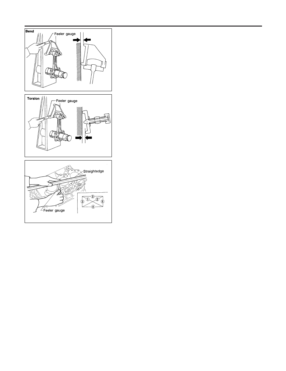
CONNECTING ROD BEND AND TORSION
NDEM0024S04
Bend:
Limit 0.15 mm (0.0059 in)
per 100 mm (3.94 in) length
Torsion:
Limit 0.30 mm (0.0118 in)
per 100 mm (3.94 in) length
If it exceeds the limit, replace connecting rod assembly.
SEM394E
CYLINDER BLOCK DISTORTION AND WEAR
NDEM0024S05
1.
Clean upper face of cylinder block and measure the distortion.
Limit:
0.10 mm (0.0039 in)
2.
If out of specification, resurface it.
The resurfacing limit is determined by cylinder head resurfac-
ing in engine.
Amount of cylinder head resurfacing is “A”.
Amount of cylinder block resurfacing is “B”.
The maximum limit is as follows:
A + B = 0.2 mm (0.008 in)
Nominal cylinder block height from crankshaft center:
227.60 - 227.70 mm (8.9606 - 8.9645 in)
3.
If necessary, replace cylinder block.
CYLINDER BLOCK
Inspection (Cont’d)
EM-50
SEM320A
SEM321AA
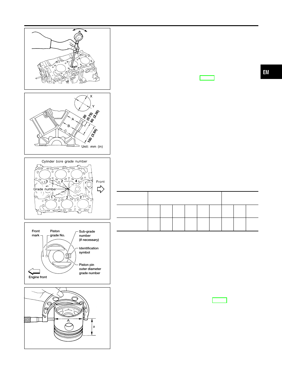
PISTON-TO-BORE CLEARANCE
NDEM0024S06
1.
Using a bore gauge, measure cylinder bore for wear, out-of-
round and taper.
Standard inner diameter:
Except for No. 5 cylinder
91.500 - 91.530 mm (3.6024 - 3.6035 in)
For No. 5 cylinder
91.515 – 91.545 mm (3.6029 – 3.6041 in)
Refer to “Cylinder Block”, EM-65.
Wear limit:
0.20 mm (0.0079 in)
If it exceeds the limit, rebore all cylinders. Replace cylinder block
if necessary.
Out-of-round (X − Y) standard:
0.015 mm (0.0006 in)
Taper (A − B or A − C) standard:
0.015 mm (0.0006 in)
2.
Check for scratches and seizure. If seizure is found, hone it.
SEM557AA
WEM098
쐌
If both cylinder block and piston are replaced with new
ones, select piston of the same grade number according
to the following table. These numbers are punched on
cylinder block and piston in either Arabic or Roman
numerals.
Combination of grade number for cylinder bore and piston
For No. 3, 4 and 5 cylinders
For No. 1, 2 and 6
cylinders
Cylinder bore
grade No.
1
2
3
4
5
6
1
2
3
Piston grade
No.
2-1
3-2
3-3
4-4
4-5
5-6
1
2
3
SEM258C
3.
Measure piston skirt diameter.
Piston diameter “A”:
Refer to “AVAILABLE PISTON”, EM-66.
Measuring point “a” (Distance from the top):
49.0 mm (1.929 in)
4.
Check that piston-to-bore clearance is within specification.
Piston-to-bore clearance “B”:
0.025 - 0.045 mm (0.0010 - 0.0018 in) for No. 1, 2 and
6 cylinders
GI
MA
LC
EC
FE
AT
AX
SU
BR
ST
RS
BT
HA
SC
EL
IDX
CYLINDER BLOCK
Inspection (Cont’d)
EM-51
0.015 - 0.025 mm (0.0006 - 0.0010 in) for No. 3 and 4
cylinders
0.030 - 0.040 mm (0.0012 - 0.0016 in) for No. 5 cylin-
der
5.
Determine piston oversize according to amount of cylinder
wear.
Oversize pistons are available for service. Refer to “AVAIL-
ABLE PISTON”, EM-66.
6.
Cylinder bore size is determined by adding piston-to-bore
clearance to piston diameter “A”.
Rebored size calculation:
D = A + B − C
where,
D: Bored diameter
A: Piston diameter as measured
B: Piston-to-bore clearance
C: Honing allowance 0.02 mm (0.0008 in)
7.
Install main bearing caps, and tighten to the specified torque
to prevent distortion of cylinder bores in final assembly.
8.
Cut cylinder bores.
쐌
When any cylinder needs boring, all other cylinders must
also be bored.
쐌
Do not cut too much out of cylinder bore at a time. Cut
only 0.05 mm (0.0020 in) or so in diameter at a time.
9.
Hone cylinders to obtain specified piston-to-bore clearance.
10. Measure finished cylinder bore for out-of-round and taper.
쐌
Measurement should be done after cylinder bore cools
down.
SEM316A
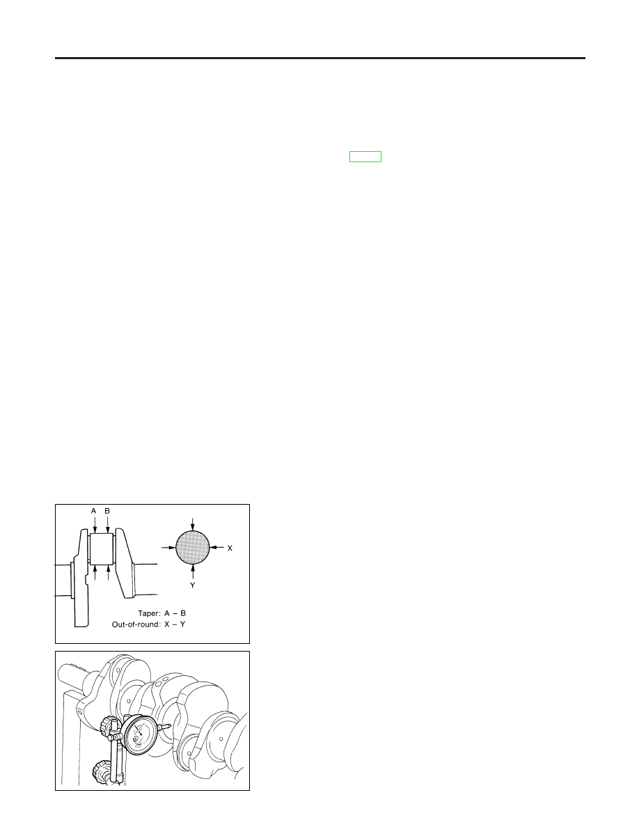
CRANKSHAFT
NDEM0024S07
1.
Check crankshaft main and pin journals for score, wear or
cracks.
2.
With a micrometer, measure journals for taper and out-of-
round.
Out-of-round (X − Y):
Less than 0.005 mm (0.0002 in)
Taper (A − B):
Less than 0.005 mm (0.0002 in)
SEM434
3.
Measure crankshaft runout.
Runout (Total indicator reading):
Less than 0.10 mm (0.0039 in)
CYLINDER BLOCK
Inspection (Cont’d)
EM-52
SEM208E
BEARING CLEARANCE
NDEM0024S08
쐌
Either of the following two methods may be used, however,
method A gives more reliable results and is preferable.
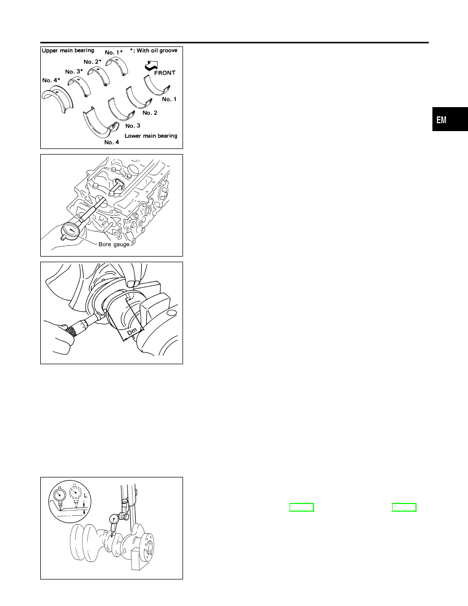
Method A (Using bore gauge & micrometer)
Main Bearing
NDEM0024S0801
1.
Set main bearings in their proper positions on cylinder block
and main bearing cap.
SEM505A
2.
Install main bearing cap to cylinder block.
Tighten all bolts in correct order in two or three stages.
3.
Measure inner diameter “A” of each main bearing.
AEM033
4.
Measure outer diameter “Dm” of each crankshaft main journal.
5.
Calculate main bearing clearance.
No. 1 Main bearing clearance (A - Dm)
Standard
0.030 - 0.048 mm (0.0012 - 0.0019 in)
Limit
0.060 mm (0.0024 in)
No. 2, 3 and No. 4 Main bearing clearance (A − Dm):
Standard
0.038 - 0.065 mm (0.0015 - 0.0026 in)
Limit
0.080 mm (0.0031 in)
6.
If it exceeds the limit, replace bearing.
7.
If clearance cannot be adjusted within the standard of any
bearing, grind crankshaft journal and use undersized bearing.
SEM184A
a.
When grinding crankshaft journal, confirm that “L” dimension in
fillet roll is more than the specified limit.
“L”: 0.1 mm (0.004 in)
b.
Refer to “Crankshaft”, EM-67 and “UNDER SIZE”, EM-68 for
grinding crankshaft and available service parts.
GI
MA
LC
EC
FE
AT
AX
SU
BR
ST
RS
BT
HA
SC
EL
IDX
CYLINDER BLOCK
Inspection (Cont’d)
EM-53
SEM508A
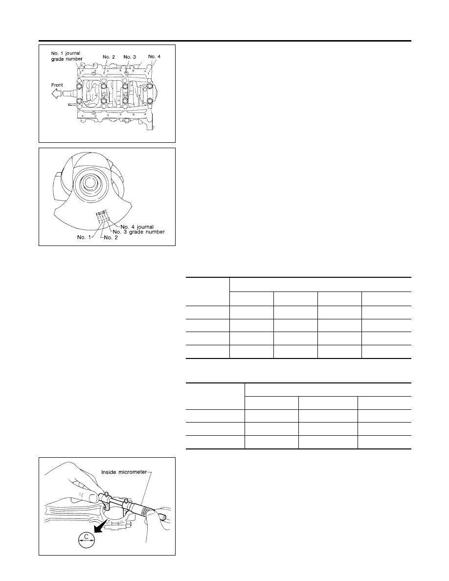
8.
If crankshaft is reused, measure main bearing clearances and
select thickness of main bearings.
If crankshaft is replaced with a new one, it is necessary to
select thickness of main bearings as follows:
a.
Grade number of each cylinder block main journal is punched
on the respective cylinder block. These numbers are punched
in either Arabic or Roman numerals.
SEM167B
b.
Grade number of each crankshaft main journal is punched on
the respective crankshaft. These numbers are punched in
either Arabic or Roman numerals.
c.
Select main bearing with suitable thickness according to the
following example or table.
Main bearing grade number
No. 1 main bearing
(Identification color):
Crankshaft
main journal
grade number
Cylinder block main journal grade number
3
4
5
6
3
0 (Black)
1 (Brown)
2 (Green)
3 (Yellow)
4
1 (Brown)
2 (Green)
3 (Yellow)
4 (Blue)
5
2 (Green)
3 (Yellow)
4 (Blue)
5 (Pink)
6
3 (Yellow)
4 (Blue)
5 (Pink)
6 (Purple)
No. 2, 3 and No. 4 main bearings
(Identification color):
Crankshaft journal
grade number
Main journal grade number
0
1
2
0
0 (Black)
1 (Brown)
2 (Green)
1
1 (Brown)
2 (Green)
3 (Yellow)
2
2 (Green)
3 (Yellow)
4 (Blue)
AEM027
Connecting Rod Bearing (Big end)
NDEM0024S0802
1.
Install connecting rod bearing to connecting rod and cap.
2.
Install connecting rod cap to connecting rod.
Tighten bolts to the specified torque.
3.
Measure inner diameter “C” of each bearing.
CYLINDER BLOCK
Inspection (Cont’d)
EM-54
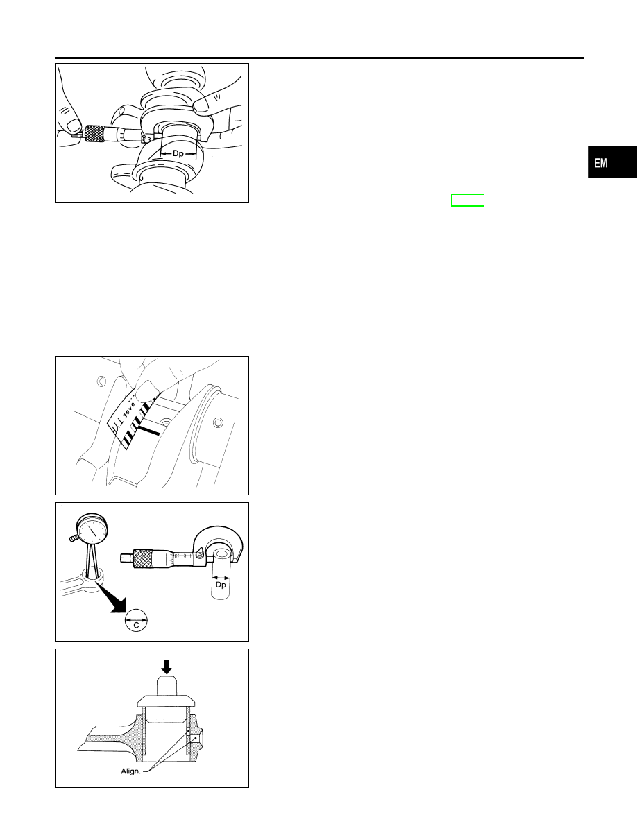
AEM034
4.
Measure outer diameter “Dp” of each crankshaft pin journal.
5.
Calculate connecting rod bearing clearance.
Connecting rod bearing clearance (C − Dp):
Standard
0.024 - 0.064 mm (0.0009 - 0.0025 in)
Limit
0.090 mm (0.0035 in)
6.
If it exceeds the limit, replace bearing.
7.
If clearance cannot be adjusted within the standard of any
bearing, grind crankshaft journal and use undersized bearing.
Refer to step 7 of “Main Bearing”, EM-53.
EM142
Method B (Using plastigage)
CAUTION:
쐌
Do not turn crankshaft or connecting rod while plastigage
is being inserted.
쐌
When bearing clearance exceeds the specified limit,
ensure that the proper bearing has been installed. Then if
excessive bearing clearance exists, use a thicker main
bearing or undersized bearing so that the specified bear-
ing clearance is obtained.
SEM673E
CONNECTING ROD BUSHING CLEARANCE (SMALL
END)
NDEM0024S09
1.
Measure inner diameter “C” of bushing.
2.
Measure outer diameter “Dp” of piston pin.
3.
Calculate connecting rod bushing clearance.
Connecting rod bushing clearance = C − Dp
Standard: 0.005 - 0.017 mm (0.0002 - 0.0007 in)
Limit: 0.023 mm (0.0009 in)
If it exceeds the limit, replace connecting rod assembly or connect-
ing rod bushing and/or piston set with pin.
SEM062A
REPLACEMENT OF CONNECTING ROD BUSHING
(SMALL END)
NDEM0024S10
1.
Drive in small end bushing until it is flush with end surface of
rod.
Be sure to align the oil holes.
2.
After driving in small end bushing, ream the bushing so that
clearance between connecting rod bushing and piston pin is
the specified value.
Clearance between connecting rod bushing and piston
pin:
0.005 - 0.017 mm (0.0002 - 0.0007 in)
GI
MA
LC
EC
FE
AT
AX
SU
BR
ST
RS
BT
HA
SC
EL
IDX
CYLINDER BLOCK
Inspection (Cont’d)
EM-55
SEM400F
Assembly
NDEM0025
PISTON
NDEM0025S01
1.
Install new snap ring on one side of piston pin hole.
2.
Heat piston to 60 to 70°C (140 to 158°F) and assemble piston,
piston pin, connecting rod and new snap ring.
쐌
Align the direction of piston and connecting rod.
쐌
Numbers stamped on connecting rod and cap correspond
to each cylinder.
쐌
After assembly, make sure connecting rod swings
smoothly.
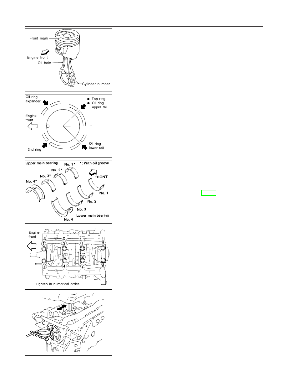
SEM160B
3.
Set piston rings as shown.
SEM208E
CRANKSHAFT
NDEM0025S02
1.
Set main bearings in their proper positions on cylinder block
and main bearing cap.
쐌
Confirm that correct main bearings are used.
쐌
Apply new engine oil to bearing surfaces.
Refer to “BEARING CLEARANCE”, EM-53.
SEM550EA
2.
Install crankshaft and main bearing caps and tighten bolts to
the specified torque.
쐌
Prior to tightening bearing cap bolts, place bearing cap in
its proper position by shifting crankshaft in the axial direc-
tion.
쐌
Tighten bearing cap bolts gradually in two or three stages.
Start with center bearing and move outward sequentially.
쐌
After securing bearing cap bolts, make sure crankshaft
turns smoothly by hand.
쐌
Lubricate threads and seat surfaces of the bolts with new
engine oil.
SEM158B
3.
Measure crankshaft end play.
Crankshaft end play:
Standard
0.050 - 0.170 mm (0.0020 - 0.0067 in)
Limit
0.30 mm (0.0118 in)
If beyond the limit, replace bearing with a new one.
CYLINDER BLOCK
Assembly
EM-56
SEM159B
4.
Install connecting rod bearings in connecting rods and con-
necting rod caps.
쐌
Confirm that correct bearings are used.
Refer to “Connecting Rod Bearing (Big End)”, EM-54.
쐌
Install bearings so that oil hole in connecting rod aligns with oil
hole of bearing.
SEM620
5.
Install pistons with connecting rods.
a.
Install them into corresponding cylinders with Tool.
쐌
Be careful not to scratch cylinder wall by connecting rod.
쐌
Arrange so that front mark on piston head faces toward
front of engine.
EM329
b.
Install connecting rod bearing caps.
쐌
Lubricate threads and seat surfaces with new engine oil.
Tighten connecting rod bearing cap nuts to the specified
torque.
: Connecting rod bearing nut
(1) Tighten to 14 to 16 N·m (1.4 to 1.6 kg-m, 10 to 12
ft-lb).
(2) Turn nuts 60 to 65 degrees clockwise. If an angle
wrench is not available, tighten nuts to 38 to 44 N·m
(3.9 to 4.5 kg-m, 28 to 33 ft-lb).
SEM512A
6.
Measure connecting rod side clearance.
Connecting rod side clearance:
Standard
0.20 - 0.35 mm (0.0079 - 0.0138 in)
Limit
0.40 mm (0.0157 in)
If beyond the limit, replace connecting rod and/or crankshaft.
SEM338F
7.
Install rear oil seal retainer.
GI
MA
LC
EC
FE
AT
AX
SU
BR
ST
RS
BT
HA
SC
EL
IDX
CYLINDER BLOCK
Assembly (Cont’d)
EM-57
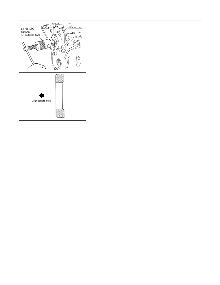
SEM916AA
REPLACING PILOT CONVERTER
NDEM0025S03
1.
Remove pilot converter.
SEM537E
2.
Install pilot converter.
CYLINDER BLOCK
Assembly (Cont’d)
EM-58
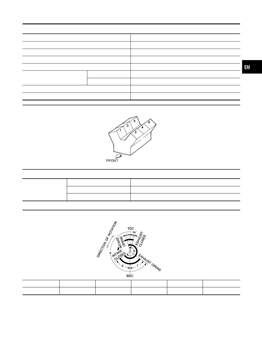
General Specifications
NDEM0026
Cylinder arrangement
V-6
Displacement
3,275 cm
3
(199.84 cu in)
Bore and stroke
91.5 x 83 mm (3.602 x 3.27 in)
Valve arrangement
OHC
Firing order
1-2-3-4-5-6
Number of piston rings
Compression
2
Oil
1
Number of main bearings
4
Compression ratio
8.9
Cylinder number
SEM713A
Unit: kPa (kg/cm
2
, psi)/300 rpm
Compression pressure
Standard
1,196 (12.2, 173)
Minimum
883 (9.0, 128)
Differential limit between cylinders
98 (1.0, 14)
Unit: degree
Valve timing
EM120
a
b
c
d
e
f
240
244
4
60
9
51
GI
MA
LC
EC
FE
AT
AX
SU
BR
ST
RS
BT
HA
SC
EL
IDX
SERVICE DATA AND SPECIFICATIONS (SDS)
General Specifications
EM-59
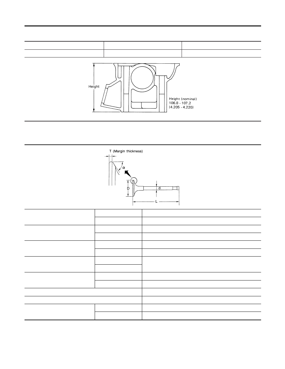
Cylinder Head
NDEM0027
Unit: mm (in)
Standard
Limit
Head surface distortion
Less than 0.03 (0.0012)
0.1 (0.004)
SEM082B
Valve
NDEM0028
VALVE
NDEM0028S01
Unit: mm (in)
SEM188
Valve head diameter “D”
Intake
42.0 - 42.2 (1.654 - 1.661)
Exhaust
35.0 - 35.2 (1.378 - 1.386)
Valve length “L”
Intake
125.3 - 125.9 (4.933 - 4.957)
Exhaust
124.2 - 124.8 (4.890 - 4.913)
Valve stem diameter “d”
Intake
6.965 - 6.980 (0.2742 - 0.2748)
Exhaust
7.965 - 7.970 (0.3136 - 0.3138)
Valve seat angle “
α
”
Intake
45°15
′
- 45°45
′
Exhaust
Valve margin “T”
Intake
1.15 - 1.45 (0.0453 - 0.0571)
Exhaust
1.35 - 1.65 (0.0531 - 0.0650)
Valve margin “T” limit
More than 0.5 (0.020)
Valve stem end surface grinding limit
Less than 0.2 (0.008)
Valve clearance
Intake
0 (0)
Exhaust
0 (0)
SERVICE DATA AND SPECIFICATIONS (SDS)
Cylinder Head
EM-60
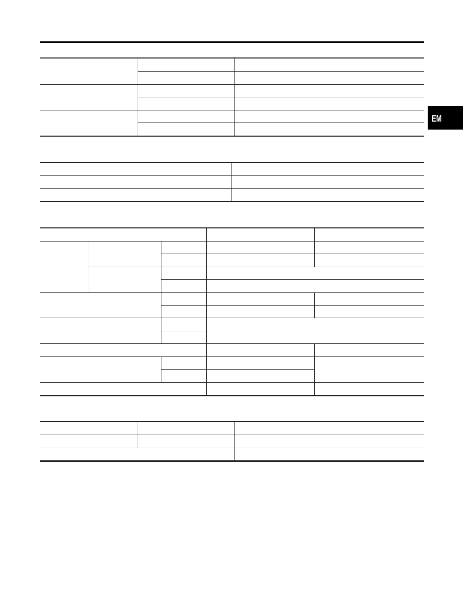
VALVE SPRING
NDEM0028S02
Free height
Outer
51.2 mm (2.016 in)
Inner
44.1 mm (1.736 in)
Pressure
Outer
523.7 N (53.4 kg, 117.7 lb) at 30.0 mm (1.181 in)
Inner
255.0 N (26.0 kg, 57.3 lb) at 25.0 mm (0.984 in)
Out-of-square
Outer
2.2 mm (0.087 in)
Inner
1.9 mm (0.075 in)
HYDRAULIC VALVE LIFTER
NDEM0028S03
Unit: mm (in)
Lifter outside diameter
15.947 - 15.957 (0.6278 - 0.6282)
Lifter guide inside diameter
16.000 - 16.013 (0.6299 - 0.6304)
Clearance between lifter and lifter guide
0.043 - 0.066 (0.0017 - 0.0026)
VALVE GUIDE
NDEM0028S04
Unit: mm (in)
Standard
Service
Valve guide
Outer diameter
Intake
11.023 - 11.034 (0.4340 - 0.4344)
11.223 - 11.234 (0.4418 - 0.4423)
Exhaust
12.023 - 12.034 (0.4733 - 0.4738)
12.223 - 12.234 (0.4812 - 0.4817)
Inner diameter (Finished
size)
Intake
7.000 - 7.018 (0.2756 - 0.2763)
Exhaust
8.000 - 8.011 (0.3150 - 0.3154)
Cylinder head valve guide hole diameter
Intake
10.975 - 10.996 (0.4321 - 0.4329)
11.175 - 11.196 (0.4400 - 0.4408)
Exhaust
11.975 - 11.996 (0.4715 - 0.4723)
12.175 - 12.196 (0.4793 - 0.4802)
Interference fit of valve guide
Intake
0.027 - 0.059 (0.0011 - 0.0023)
Exhaust
Standard
Max. tolerance
Stem to guide clearance
Intake
0.020 - 0.053 (0.0008 - 0.0021)
0.10 (0.0039)
Exhaust
0.030 - 0.049 (0.0012 - 0.0019)
Valve deflection limit
—
0.20 (0.0079)
ROCKER SHAFT AND ROCKER ARM
NDEM0028S05
Unit: mm (in)
Rocker shaft
Outer diameter
17.979 - 18.000 (0.7078 - 0.7087)
Rocker arm
Inner diameter
18.007 - 18.028 (0.7089 - 0.7098)
Clearance between rocker arm and rocker shaft
0.007 - 0.049 (0.0003 - 0.0019)
GI
MA
LC
EC
FE
AT
AX
SU
BR
ST
RS
BT
HA
SC
EL
IDX
SERVICE DATA AND SPECIFICATIONS (SDS)
Valve (Cont’d)
EM-61
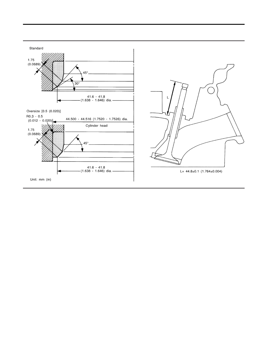
Valve Seat
NDEM0029
INTAKE VALVE SEAT
NDEM0029S01
SEM639F
SERVICE DATA AND SPECIFICATIONS (SDS)
Valve Seat
EM-62
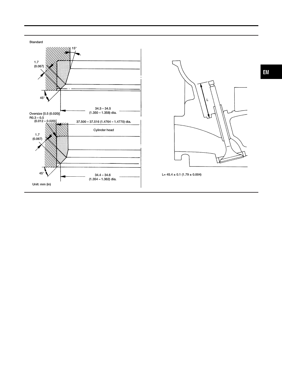
EXHAUST VALVE SEAT
NDEM0029S02
AEM455
GI
MA
LC
EC
FE
AT
AX
SU
BR
ST
RS
BT
HA
SC
EL
IDX
SERVICE DATA AND SPECIFICATIONS (SDS)
Valve Seat (Cont’d)
EM-63
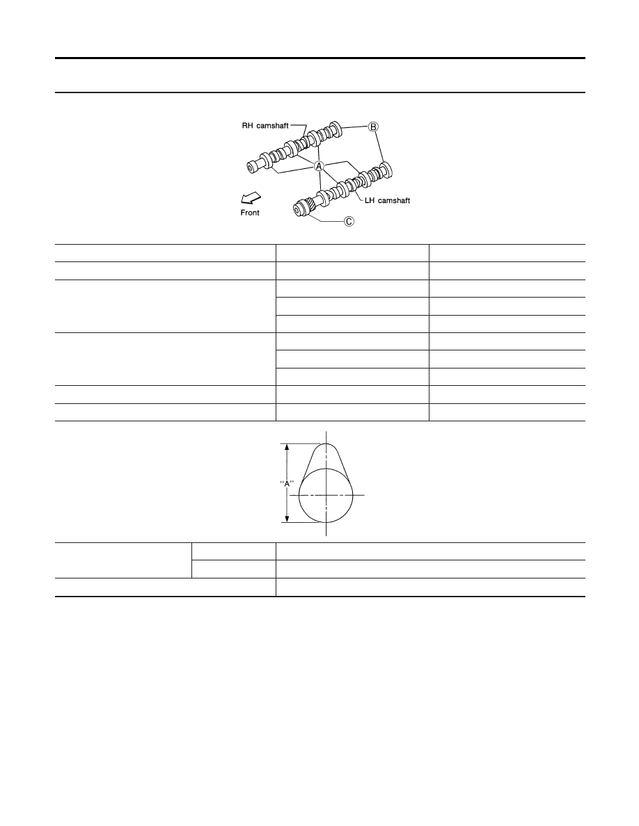
Camshaft and Camshaft Bearing
NDEM0030
Unit: mm (in)
SEM893BA
Standard
Max. tolerance
Camshaft journal to bearing clearance
0.060 - 0.105 (0.0024 - 0.0041)
0.15 (0.0059)
Inner diameter of camshaft bearing
A: 47.000 - 47.025 (1.8504 - 1.8514)
—
B: 42.500 - 42.525 (1.6732 - 1.6742)
—
C: 48.000 - 48.025 (1.8898 - 1.8907)
—
Outer diameter of camshaft journal
A: 46.920 - 46.940 (1.8472 - 1.8480)
—
B: 42.420 - 42.440 (1.6701 - 1.6709)
—
C: 47.920 - 47.940 (1.8866 - 1.8874)
—
Camshaft runout [TIR*]
Less than 0.04 (0.0016)
0.1 (0.004)
Camshaft end play
0.03 - 0.06 (0.0012 - 0.0024)
—
EM671
Cam height “A”
Intake
38.943 - 39.133 (1.5332 - 1.5407)
Exhaust
38.943 - 39.133 (1.5332 - 1.5407)
Wear limit of cam height
0.15 (0.0059)
*Total indicator reading
SERVICE DATA AND SPECIFICATIONS (SDS)
Camshaft and Camshaft Bearing
EM-64
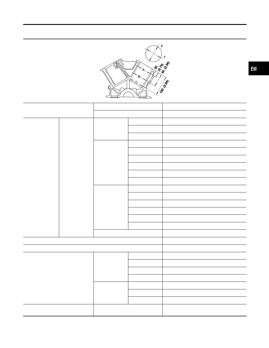
Cylinder Block
NDEM0031
Unit: mm (in)
SEM321A
Surface flatness
Standard
Less than 0.03 (0.0012)
Limit
0.10 (0.0039)
Cylinder bore
Inner diameter
Standard (for No. 1,
2 and 6 cylinders)
Grade No. 1
91.500 - 91.510 (3.6024 - 3.6027)
Grade No. 2
91.510 - 91.520 (3.6027 - 3.6031)
Grade No. 3
91.520 - 91.530 (3.6031 - 3.6035)
Standard (for No. 3
and 4 cylinders)
Grade No. 1
91.500 - 91.505 (3.6024 - 3.6026)
Grade No. 2
91.505 - 91.510 (3.6026 - 3.6027)
Grade No. 3
91.510 - 91.515 (3.6027 - 3.6029)
Grade No. 4
91.515 - 91.520 (3.6029 - 3.6031)
Grade No. 5
91.520 - 91.525 (3.6031 - 3.6033)
Grade No. 6
91.525 - 91.530 (3.6033 - 3.6035)
Standard (for No. 5
cylinder)
Grade No. 1
91.515 - 91.520 (3.6029 - 3.6031)
Grade No. 2
91.520 - 91.525 (3.6031 - 3.6033)
Grade No. 3
91.525 - 91.530 (3.6033 - 3.6035)
Grade No. 4
91.530 - 91.535 (3.6035 - 3.6037)
Grade No. 5
91.535 - 91.540 (3.6037 - 3.6039)
Grade No. 6
91.540 - 91.545 (3.6039 - 3.6041)
Wear limit
0.20 (0.0079)
Out-of-round (X − Y)
Less than 0.015 (0.0006)
Taper (A − B or A − C)
Less than 0.015 (0.0006)
Main journal inner diameter
No. 1 main journal
Grade No. 3
66.645 - 66.651 (2.6238 - 2.6240)
Grade No. 4
66.651 - 66.657 (2.6240 - 2.6243)
Grade No. 5
66.657 - 66.663 (2.6243 - 2.6245)
Grade No. 6
66.663 - 66.669 (2.6245 - 2.6248)
No. 2, 3 and 4 main
journals
Grade No. 0
66.645 - 66.654 (2.6238 - 2.6242)
Grade No. 1
66.654 - 66.663 (2.6242 - 2.6245)
Grade No. 2
66.663 - 66.672 (2.6245 - 2.6249)
Difference in inner diameter between cylin-
ders
Standard
Less than 0.05 (0.0020)
GI
MA
LC
EC
FE
AT
AX
SU
BR
ST
RS
BT
HA
SC
EL
IDX
SERVICE DATA AND SPECIFICATIONS (SDS)
Cylinder Block
EM-65
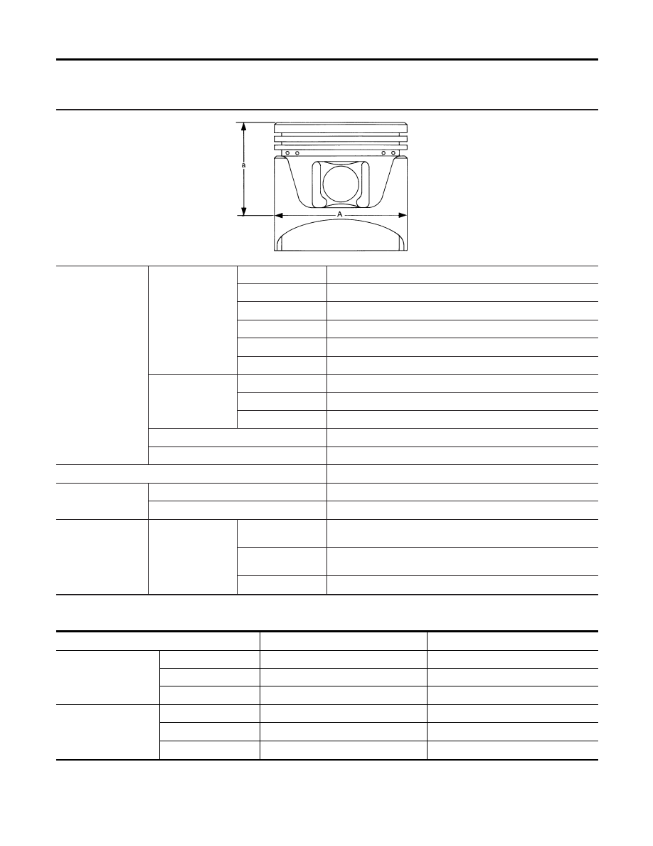
Piston, Piston Ring and Piston Pin
NDEM0032
AVAILABLE PISTON
NDEM0032S01
Unit: mm (in)
SEM882E
Piston skirt diameter
“A”
Standard (for No. 3, 4
and 5 cylinders)
Grade No. 2-1
91.480 - 91.485 (3.6016 - 3.6018)
Grade No. 3-2
91.485 - 91.490 (3.6018 - 3.6020)
Grade No. 3-3
91.490 - 91.495 (3.6020 - 3.6022)
Grade No. 4-4
91.495 - 91.500 (3.6022 - 3.6024)
Grade No. 4-5
91.500 - 91.505 (3.6024 - 3.6026)
Grade No. 5-6
91.505 - 91.510 (3.6026 - 3.6027)
Standard (for No. 1, 2
and 6 cylinders)
Grade No. 1
91.465 - 91.475 (3.6010 - 3.6014)
Grade No. 2
91.475 - 91.485 (3.6014 - 3.6018)
Grade No. 3
91.485 - 91.495 (3.6018 - 3.6022)
0.25 (0.0098) oversize (Service)
91.715 - 91.745 (3.6108 - 3.6120)
0.50 (0.0197) oversize (Service)
91.965 - 91.995 (3.6207 - 3.6218)
“a” dimension
49.0 (1.929)
Piston pin hole diam-
eter
Grade No. 0
20.969 - 20.975 (0.8255 - 0.8258)
Grade No. 1
20.975 - 20.981 (0.8258 - 0.8260)
Piston clearance to
cylinder block
Standard
For No. 1, 2 and 6 cyl-
inders
0.025 - 0.045 (0.0010 - 0.0018)
For No. 3 and 4 cylin-
ders
0.015 - 0.025 (0.0006 - 0.0010)
For No. 5 cylinder
0.030 - 0.040 (0.0012 - 0.0016)
PISTON RING
NDEM0032S02
Unit: mm (in)
Standard
Limit
Side clearance
Top
0.040 - 0.080 (0.0016 - 0.0031)
0.11 (0.0043)
2nd
0.030 - 0.070 (0.0012 - 0.0028)
0.10 (0.004)
Oil
0.015 - 0.185 (0.0006 - 0.0073)
—
Ring gap
Top
0.21 - 0.31 (0.0083 - 0.0122)
0.43 (0.0169)
2nd
0.50 - 0.60 (0.0197 - 0.0236)
0.69 (0.0272)
Oil (rail ring)
0.20 - 0.60 (0.0079 - 0.0236)
0.84 (0.0331)
SERVICE DATA AND SPECIFICATIONS (SDS)
Piston, Piston Ring and Piston Pin
EM-66
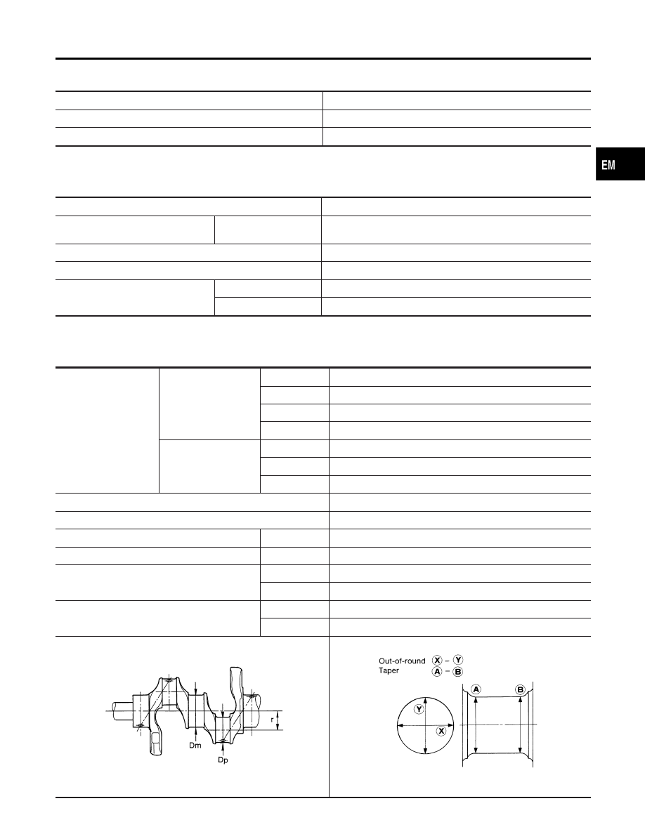
PISTON PIN
NDEM0032S03
Unit: mm (in)
Piston pin outer diameter
20.971 - 20.983 (0.8256 - 0.8261)
Interference fit of piston pin to piston
0 to -0.004 (0 to -0.0002)
Piston pin to connecting rod bushing clearance
0.005 - 0.017 (0.0002 - 0.0007)
Values measured at ambient temperature of 20°C (68°F)
Connecting Rod
NDEM0033
Unit: mm (in)
Center distance
154.1 - 154.2 (6.067 - 6.071)
Bend, torsion [per 100 (3.94)]
Limit
Bend: 0.15 (0.0059)
Torsion: 0.30 (0.0118)
Piston pin bushing inner diameter*
20.982 - 20.994 (0.8261 - 0.8265)
Connecting rod big end inner diameter
53.000 - 53.013 (2.0866 - 2.0871)
Side clearance
Standard
0.20 - 0.35 (0.0079 - 0.0138)
Limit
0.40 (0.0157)
*After installing in connecting rod
Crankshaft
NDEM0034
Unit: mm (in)
Main journal dia. “Dm”
No. 1 main journal
Grade No. 3
62.969 - 62.975 (2.4791 - 2.4793)
Grade No. 4
62.963 - 62.969 (2.4789 - 2.4791)
Grade No. 5
62.957 - 62.963 (2.4786 - 2.4789)
Grade No. 6
62.951 - 62.957 (2.4784 - 2.4786)
No. 2, 3 and 4 main jour-
nals
Grade No. 0
62.967 - 62.975 (2.4790 - 2.4793)
Grade No. 1
62.959 - 62.967 (2.4787 - 2.4790)
Grade No. 2
62.951 - 62.959 (2.4784 - 2.4787)
Pin journal dia. “Dp”
49.955 - 49.974 (1.9667 - 1.9675)
Center distance “r”
41.5 (1.634)
Out-of-round (X − Y)
Standard
Less than 0.005 (0.0002)
Taper (A − B)
Standard
Less than 0.005 (0.0002)
Runout [TIR]
Standard
Less than 0.025 (0.0010)
Limit
Less than 0.10 (0.0039)
Free end play
Standard
0.050 - 0.170 (0.0020 - 0.0067)
Limit
0.30 (0.0118)
SEM645
EM715
GI
MA
LC
EC
FE
AT
AX
SU
BR
ST
RS
BT
HA
SC
EL
IDX
SERVICE DATA AND SPECIFICATIONS (SDS)
Piston, Piston Ring and Piston Pin (Cont’d)
EM-67
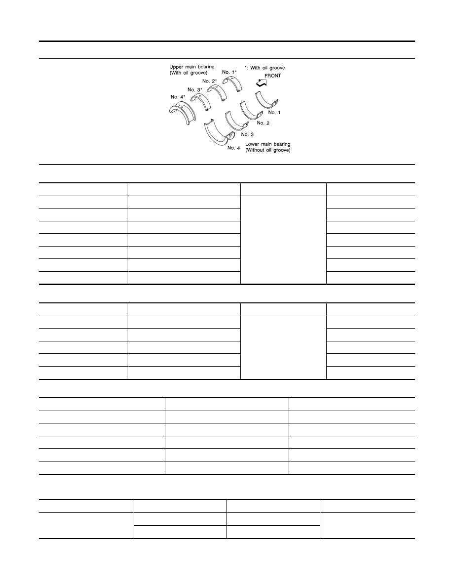
Available Main Bearing
NDEM0035
SEM327A
NO. 1 MAIN BEARING
NDEM0035S01
Grade number
Thickness “T” mm (in)
Width “W” mm (in)
Identification color
0
1.822 - 1.825 (0.0717 - 0.0719)
22.4 - 22.6 (0.882 - 0.890)
Black (A)
1
1.825 - 1.828 (0.0719 - 0.0720)
Brown (B)
2
1.828 - 1.831 (0.0720 - 0.0721)
Green (C)
3
1.831 - 1.834 (0.0721 - 0.0722)
Yellow (D)
4
1.834 - 1.837 (0.0722 - 0.0723)
Blue (E)
5
1.837 - 1.840 (0.0723 - 0.0724)
Pink (F)
6
1.840 - 1.843 (0.0724 - 0.0726)
Purple (G)
NO. 2 AND 3 MAIN BEARING
NDEM0035S02
Grade number
Thickness “T” mm (in)
Width “W” mm (in)
Identification color
0
1.817 - 1.821 (0.0715 - 0.0717)
18.9 - 19.1 (0.744 - 0.752)
Black
1
1.821 - 1.825 (0.0717 - 0.0719)
Brown
2
1.825 - 1.829 (0.0719 - 0.0720)
Green
3
1.829 - 1.833 (0.0720 - 0.0722)
Yellow
4
1.833 - 1.837 (0.0722 - 0.0723)
Blue
NO. 4 MAIN BEARING
NDEM0035S03
Grade number
Thickness “T” mm (in)
Identification color
0
1.817 - 1.821 (0.0715 - 0.0717)
Black
1
1.821 - 1.825 (0.0717 - 0.0719)
Brown
2
1.825 - 1.829 (0.0719 - 0.0720)
Green
3
1.829 - 1.833 (0.0720 - 0.0722)
Yellow
4
1.833 - 1.837 (0.0722 - 0.0723)
Blue
UNDER SIZE
NDEM0035S04
Unit: mm (in)
Thickness “T”
Main journal diameter “Dm”
0.25 (0.0098)
No. 1 main bearing
1.956 - 1.962 (0.0770 - 0.0772)
Grind so that bearing clearance is
the specified value.
No. 2, 3 and No. 4 main bearing
1.948 - 1.956 (0.0767 - 0.0770)
SERVICE DATA AND SPECIFICATIONS (SDS)
Available Main Bearing
EM-68
Available Connecting Rod Bearing
NDEM0036
CONNECTING ROD BEARING UNDERSIZE
NDEM0036S01
Unit: mm (in)
Thickness
Crank pin journal diameter “Dp”
Standard
1.502 - 1.506 (0.0591 - 0.0593)
49.955 - 49.974 (1.9667 - 1.9675)
Undersize
0.08 (0.0031)
1.542 - 1.546 (0.0607 - 0.0609)
Grind so that bearing clearance is the specified
value.
0.12 (0.0047)
1.562 - 1.566 (0.0615 - 0.0617)
0.25 (0.0098)
1.627 - 1.631 (0.0641 - 0.0642)
Miscellaneous Components
NDEM0037
Unit: mm (in)
Drive plate runout [TIR]
Less than 0.15 (0.0059)
BEARING CLEARANCE
NDEM0037S01
Unit: mm (in)
Main bearing clearance
No. 1 main bearing
Standard
0.030 - 0.048 (0.0012 - 0.0019)
Limit
0.060 (0.0024)
No. 2, 3, and No.4 main
bearing
Standard
0.038 – 0.065 (0.0015 – 0.0026)
Limit
0.080 (0.0031)
Connecting rod bearing clearance
Standard
0.024 - 0.064 (0.0009 - 0.0025)
Limit
0.090 (0.0035)
GI
MA
LC
EC
FE
AT
AX
SU
BR
ST
RS
BT
HA
SC
EL
IDX
SERVICE DATA AND SPECIFICATIONS (SDS)
Available Connecting Rod Bearing
EM-69

NOTES
Document Outline
- QUICK REFERENCE INDEX
- TABLE OF CONTENTS
- PRECAUTIONS
- PREPARATION
- NOISE, VIBRATION AND HARSHNESS (NVH) TROUBLESHOOTING
- OUTER COMPONENT PARTS
- MEASUREMENT OF COMPRESSION PRESSURE
- OIL PAN
- TIMING BELT
- OIL SEAL
- CYLINDER HEAD
- Components
- Removal
- Disassembly
- Inspection
- CYLINDER HEAD DISTORTION
- CAMSHAFT VISUAL CHECK
- CAMSHAFT RUNOUT
- CAMSHAFT CAM HEIGHT
- CAMSHAFT JOURNAL CLEARANCE
- CAMSHAFT END PLAY
- CAMSHAFT SPROCKET RUNOUT
- VALVE GUIDE CLEARANCE
- VALVE GUIDE REPLACEMENT
- VALVE SEATS
- REPLACING VALVE SEAT FOR SERVICE PARTS
- VALVE DIMENSIONS
- VALVE SPRING
- ROCKER SHAFT AND ROCKER ARM
- HYDRAULIC VALVE LIFTER
- Assembly
- Installation
- ENGINE ASSEMBLY
- CYLINDER BLOCK
- SERVICE DATA AND SPECIFICATIONS (SDS)
Wyszukiwarka
Podobne podstrony:
EM DYSTRYBUCJA
EM t 4 Ceny
EM t 6 produkcja
Poker współczesny Texas Hold'em i inne odmiany pokera (2)
Pisownia ę ą en em om
EM cz1
WYZNACZANIE STOSUNKU em ŁADUNKU ELEKTRONU DO JEGO MASY METODĄ MAGNETRONU
2 Wyznaczanie stosunku em ładunku elektronu do jego masy metodą magnetronu
EM U A wyk 11 12
IMIR drgania EM prady zmienne i Nieznany
Deutsch als Fremdsprache Em Uebungsgrammatik
2011 EM BF zadania 03
STOS-EM, 1 STUDIA - Informatyka Politechnika Koszalińska, Labki, fizyka1, fiza, fizyka
C 4, MIBM WIP PW, fizyka 2, laborki fiza(2), 31-Ruch elektronu w polu magnetycznym i elektrycznym. W
Mon. pól EM, Studia, 1-stopień, inżynierka, Ochrona Środowiska, Monitoring i bioindykacja środowiska
2011 EM BF zadania 12
referaty EM 13
Lardner Treat 'em Rough
Pomiar stosunku em metodą odchyleń w polu magnetycznym2
więcej podobnych podstron