Inductive proximity switches
Introduction
2/111
Siemens FS 10 · 2007
2
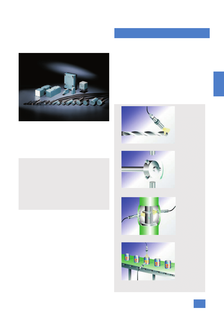
Inductive proximity switches – rugged,
precise and reliable
For contact-free detection of metal objects, proximity switches
are quite simply the most cost-effective solution. If an excellent
conductor of electricity or magnetism moves towards the sensor
or away from it, the signal automatically changes.
With their excellent repeat accuracy, they are extremely reliable.
And thanks to their wear-free operation and insensitivity to tem-
perature, noise, light and water, they have a long service life. We
have covered the complete application spectrum with a wide
range of different types and ranges.
Applications
Inductive proximity switches are the low-cost solution for non-
contact detection of metal objects. They are used in sectors in
which metal components play an important role, e.g.
• In the motor industry
• In mechanical engineering
• In the robotics industry
• In conveyor systems and
• In the paper and printing industry
The induction principle and the experience gained by Siemens
over many years have made the inductive proximity switches
what they are: extremely reliable with a very high repeat accu-
racy and long service life thanks to a lack of wearing parts as
well as their insensitivity to temperature, noise, light and water.
Our customers also benefit from the wide range of inductive
proximity switches that Siemens offers. Our complete range
meets a wide range of different requirements and leaves no
wishes unfulfilled.
Inductive proximity switches are available:
• With operating distances from 0.6 to 75 mm
• In cylindrical and cubic designs
• In the standard version as 3- and 4-wire sensors
• As 2-wire sensors for solid-state inputs
• For extra duty (65 V DC or 320 V AC/DC)
• To the IP68 degree of protection for extreme environmental
conditions
• With increased operating distances
• For welding applications
• Without a reduction factor
• As intrinsically safe sensors for potentially explosive environ-
ments.
Application examples
Highlights
• Extremely compact and rugged
• High degree of protection (IP67/IP68/IP69K)
• Correction factor 1
• High sensing ranges
• Fast switching frequencies
• Flexible mounting
• Especially suitable for small spaces
• Can be used all over the world: UL/CSA approvals
Recognition of broken drills
Recognition of positioning screws on the wheel for velocity or
direction control
Recognition of the valve position (completely open or closed)
Recognition of cans and lids

Inductive proximity switches
Introduction
2/112
Siemens FS 10 · 2007
2
The inductive proximity switches are classified in accordance
with their applications or their technical characteristics:
Configurator
A configurator for inductive proximity switches is available in the
A&D Mall. Based on the technical features required, the desired
product can be quickly and easily selected, placed in the shop-
ping cart and ordered.
Additional information is available in the Internet under:
www.siemens.com/simatic-sensors/px
SIMATIC Sensors Field of application
and special
characteristics
Voltage range
Output
Special advantages
PXI200
Sensors for standard
applications and for
PLCs
Operating distance
acc. to standard
• 10 V to 30 V DC or
15 V to 34 V DC
• 2-wire proximity switch:
1 NO contact, up to 25 mA residual
current and voltage drop suitable for
PLC inputs, minimal wiring outlay,
both current source and current sink,
power is supplied from PLC input
• 3-wire proximity switch:
1 NO or 1 NC, up to 200 mA, pnp or
npn
• 4-wire proximity switch:
1 NO and 1 NC (antivalent), pnp, up
to 200 mA
PXI300
Sensors for extra duty
• 3-wire proximity
switch:
10 to 65 V DC
• 2-wire proximity
switch:
20 to 320 V AC/DC
• 3-wire proximity switch:
1 NO or 1 NC, pnp
• 2-wire proximity switch:
1 NO or 1 NC
• Problem-free adaptation to different
rated operating voltages
• Insensitive to voltage deviations
Sensors with greater
operating distance
• 3-wire proximity
switch:
DC 10 to 30 V DC or
10 to 65 V DC
• 3-wire proximity switch:
1 NO or 1 NC, pnp, up to 300 mA
• Operating distance far above the
standard, up to three times the rated
operating distance defined in the
standard
• Wide range of mounting adjustment
• A smaller type can be selected for
the required operating distance
• Reduction of actuation distance is
corrected for non-ferrous metals
Sensors for extreme
environmental condi-
tions (IP68 / IP69K)
• 2-wire proximity
switch:
20 to 320 V AC/DC
• 3-wire proximity
switch:
15 to 34 V DC,
10 to 65 V DC
• 4-wire proximity
switch:
15 to 34 V DC
• 3-wire proximity switch:
1 NO or 1 NC, pnp up to 300 mA
• 4-wire proximity switch:
1 NO and 1 NC (antivalent), pnp,
up to 200 mA
• Can be used under extreme environ-
mental conditions according to IP68
by use of a well-sealed enclosure
with a special casting compound
PXI400
Sensors without a
reduction factor; for
welding applications
• 3-wire proximity
switch:
10 to 30 V DC
• 3-wire proximity switch:
1 NO, pnp up to 200 mA
• No reduction factor for non-ferrous
metals
• Welding/magnetic field resistant
up to 160 mT r.m.s. = approx. 21 kA
at 25.4 mm
PXI600
Sensors for Ex
Zone 2
Approval for gas :
EX II 3G EEx nA II T6 X
Approval for dust :
EX II 3D IP65 T 80 °C X
• 4-wire proximity
switch:
10 to 30 V DC
• 4-wire proximity switch:
1 NO + 1 NC, pnp up to 200 mA
PXI900
Pressure-resistant sen-
sors up to 500 bar
(7250 psi)
• 3-wire proximity
switch:
10 to 30 V DC
• 3-wire proximity switch:
1 NO, pnp up to 200 mA
• Operating distance: 3 mm
• Suitable for extreme dynamic me-
chanical stress
• Easy to install: The proximity switches
can be screw fastened against a
stop, no adjustment required
• Sensing face seal is gas-tight
Sensors with analog
output
• 3-wire proximity
switch:
10 to 30 V DC
• Voltage output 0 to 5 V DC
• Current output 1 to 5 mA
• Non-linearized design
Inductive proximity switches
Introduction
2/113
Siemens FS 10 · 2007
2
Approvals
3RG40, 3RG41 devices with M 12 or M 18 connectors as well as
terminal compartments are UL and CSA listed.
For a complete overview, see the Appendix.
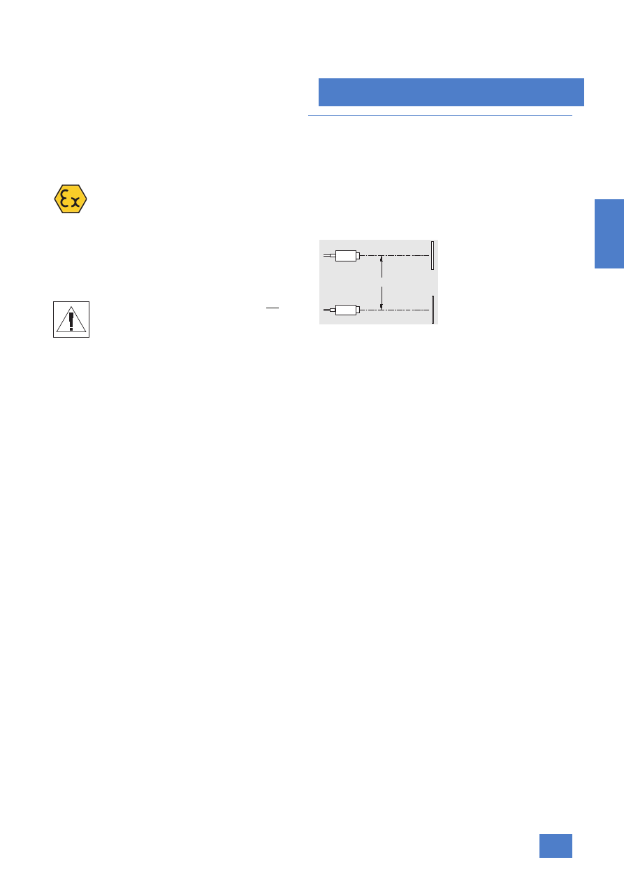
Sensors for Ex Zone 2/22
The inductive proximity switches PXI600 are ap-
proved according to EU Guideline 94/9/EG (ATEX)
Appendix VIII
The approval is valid for:
• Gas EX II 3G EEx nA II T6 X and
• Dust EX II 3D IP65 T 80 °C X
The functionality of the inductive proximity switches with ATEX
approval is identical to that of the standard proximity switches.
Personal safety
Use of the inductive proximity switches is not per-
missible for applications in which the safety of per-
sons is dependent on the function of the proximity
switch.
■
Design
Specifications
IEC 60947-5-2, EN 60947-5-2 (VDE 0660, Part 208)
Minimum clearance
The proximity switches must not interfere with each other. There-
fore a minimum distance a must be observed between two sen-
sors.
The distance a depends on the sensor size and type (see dia-
grams in the dimension drawings).
Connectors
For the cylindrical types, 8 mm combined plugs or plugs with
M12 threads are offered as standard (3-pole or 4-pole). A cable
plug is additionally required for the plug-and-socket connec-
tions, see under Accessories. As an option, plugs with an M18
thread (3-pole) are also offered for the M 18 and M 30 types.
Cables
In general, highly flexible cables with oil-resistant outer sheaths
of polyurethane (PUR) are used that are 2m long as standard.
For applications where cables come into contact with acids or
alkalis, please order devices with PVC cables.
For devices used in applications to UL and CSA, PVC cables
must be ordered.
Alternative cable lengths and materials on request.
Cable length
For the proximity switches, long cables cause:
• Capacitive loading of the output
• Increased injection of interference
Cables should be shorter than 300 m even under favorable con-
ditions.
Cable routing
The connecting leads of the proximity switches should not be
routed in a cable channel alongside cables that are used to
switch inductive loads (e.g. contactor coils, solenoid valves, mo-
tors) or that carry the current for solid-state motor drives.
The cable lengths should be kept as short as possible; with fa-
vorable routing (small coupling capacitance, small interference
voltages), the length may be up to 300 m.
Interference can be reduced by means of the following mea-
sures:
• Distance from interfering cables > 100 mm
• Shielding
• Connection of coils (of contactors, relays or solenoid valves)
with RC elements or varistors.
NSD0_00801
NSD0_00796
a

Inductive proximity switches
Introduction
2/114
Siemens FS 10 · 2007
2
Degree of protection
Degree of protection
according to IEC 60529
Explanation
Test conditions / notes
IP67
6 Protection against the entry of dust. Complete con-
tact protection (electric).
7 Protection against water when the enclosure is
immersed in water under given pressure and time
conditions. Entry of water in harmful amounts is not
allowed.
Test conditions:
• Immersion depth 1 m
• Time 30 min
If a device is subjected to water or damp over long periods,
IP68 degree of protection must be selected.
IP68
6 Protection against the entry of dust. Complete con-
tact protection (electric).
8 Protection against water when submersed.
The leak test is based on IEC 60068-2-17, test ql. Contrary
to the standard, the tested device is stored in steam and
not in water since greater stress exists with this type of stor-
age.
Parameters:
• Initial conditions: Operating distance for
T
amb
= 25 °C ± 5 °C
• Test liquid: tap water
• Temperature of test liquid: 105 °C – 5 °C
• Test pressure: 12 N/cm (1.2 bar)
• Stress duration: 5 days
• Subsequent treatment: drying at room temperature and
cooling. The final measurement is made as soon as the de-
vice under test has reached room temperature.
• Final measurement: Operating distance at T
amb
= 25 °C ±
5 °C. The permissible change is ± 10% of the initial state
IP69K
6 Protection against the entry of dust. Complete con-
tact protection (electric).
9K Protection against water with high-pressure jet clean-
ing. (i.e.: water directed at extremely high pressure
onto the enclosure from all directions must not result
in harmful effects.)

Inductive proximity switches
Introduction
2/115
Siemens FS 10 · 2007
2
■
Function
A high-frequency alternating field is generated in the proximity
switch and emerges at the "sensing face". The physical size of
this alternating field determines the "range" of the device. When
a material that is a good conductor of electricity and/or magne-
tism comes into close proximity with the sensing surface, the
field is damped. Both states (field damped or undamped) are
evaluated in the proximity switch and result in a change in the
output state of the switch.
Built-in protection
The protective circuits built into most proximity switches (see se-
lection data) make them easy to handle and protect the devices
from damage.
Protection is possible against
• Spurious signals
• Short-circuit and overload (DC)
• Swapped connectors
• Wire-break (connection L– or L+),
• Overvoltage peaks
• Radio interference
Spurious signal suppression
When the operating voltage is applied, the "damped" status is
simulated due to the transient condition of the sensor inductor –
even when an activation element is not present. Spurious signal
suppression prevents the output switching during this period.
Short-circuit and overload protection
All DC voltage devices with three-wire and four-wire connections
are equipped with short-circuit and overload protection. Short-
circuits between the output and the operating voltage connec-
tions do not damage the proximity switches, and may be occur
permanently; an unlimited overload is also permissible. For the
duration of the short circuit, the LEDs are not functional.
Polarity reversal protection
All DC voltage devices with three-wire and four-wire connections
are protected against reverse polarity at all connections.
Wire-break protection
The DC version is designed such that when a wire-break occurs
in any connection, the proximity switch does not output a faulty
signal (not for 3RG46 and all 4-wire proximity switches). A faulty
signal is any non-zero signal that is active for more than 2 ms
and whose current is larger than the residual current.
Inductive interference protection
When inductive loads are disconnected, the output voltage rises
(without protective elements) to high values whereby the output
transistor can be destroyed. The proximity switches are there-
fore equipped with a Zener diode at the output which limits the
disconnection voltage to a safe value (3-wire proximity switch).
When inductive loads are connected at currents > 100 mA and
simultaneously a switching frequency > 10 Hz, it is recom-
mended that a freewheeling diode be directly connected across
the load (due to the power losses in the built-in Zener diode).
Protection against radio interference
The high-frequency susceptibility has been sufficiently reduced
to comply with IEC 61000-4-3, Level 3 (testing level 10 V/m).
Protection against electrostatic charging
The devices are constructed such that electrostatic charging to
IEC 61000-4-3, Level 3 (8 kV) does not damage the devices.
Electromagnetic compatibility (EMC)
All inductive proximity switches meet the protection require-
ments of EMC guideline No. 89/336/EEC. This is confirmed by
application of the EN 60 947-5-2 standard.
The following EMC standards are applicable for the individual
tests:
• EN 55011, IEC-CISPR 11
• EN 55022, IEC-CISPR 22
• IEC 61000-4-2, Level 3
• IEC 61000-4-3, Level 3
• IEC 61000-4-4, Level 3
• IEC 61000-4-6.
Displays (LEDs)
Most proximity switches are equipped with one or two LEDs.
The yellow LED indicates the operating status:
• For proximity switches with NO function:
Proximity switch damped = LED lit
• For proximity switches with NC function:
Proximity switch not damped = LED lit
• For proximity switches with NO and NC function:
Proximity switches damped = LED lit
The green LED indicates that the operating voltage is applied.
This function is only available in certain devices.

Inductive proximity switches
Introduction
2/116
Siemens FS 10 · 2007
2
■
Technical specifications
General technical specifications
1) Up to +70 °C with 3RG41 and 3RG46.
2) Maximum switching current for three-wire proximity switches for stan-
dard duty at operating temperatures > 50 °C is 150 mA.
Fastening nuts
Differential travel H
H ≤ max. 0.2 s
r
Max. permissible cable length (unshielded)
• AC
100 m
• DC
300 m
Degree of protection
• With buried cable
IP67
• With connector and cable plug
IP67
• With terminal compartment
IP65
• Proximity switches for extreme environmen-
tal conditions
IP68 or IP69 K
• Proximity switch without a reduction factor
- With brass enclosure
IP67
- With stainless steel enclosure
IP68
Ambient temperature
• in operation
–25 ... + 85 °C
1
)
2
)
• During storage
–40 ... + 85 °C
1
)
Shock resistance
30 × g, 18 ms duration
Resistance to vibration
55 Hz, 1 mm amplitude
Reduction factor
• Proximity switch for flush or non-flush
mounting (typical values)
- Stainless steel
0.7 ... 0.9
- Aluminum
0.35 ... 0.5
- Copper
0.2 ... 0.4
- Brass
0.3 ... 0.6
• Proximity switch without a reduction factor
1
Voltage drop
• 2-wire proximity switch
≤
8 V
• 3-wire proximity switch
≤
2.5 V
• 4-wire proximity switch
≤
2.5 V
Design
Material
Tightening torque
Nm
M8
Brass
2
Stainless steel
5
M12
Brass
10
Molded plastic
1
Stainless steel
25
M14
Molded plastic
0.5
M18
Brass
20
Molded plastic
3
Stainless steel
50
M30
Brass
40
Molded plastic
5
Stainless steel
100
Inductive proximity switches
Introduction
2/117
Siemens FS 10 · 2007
2
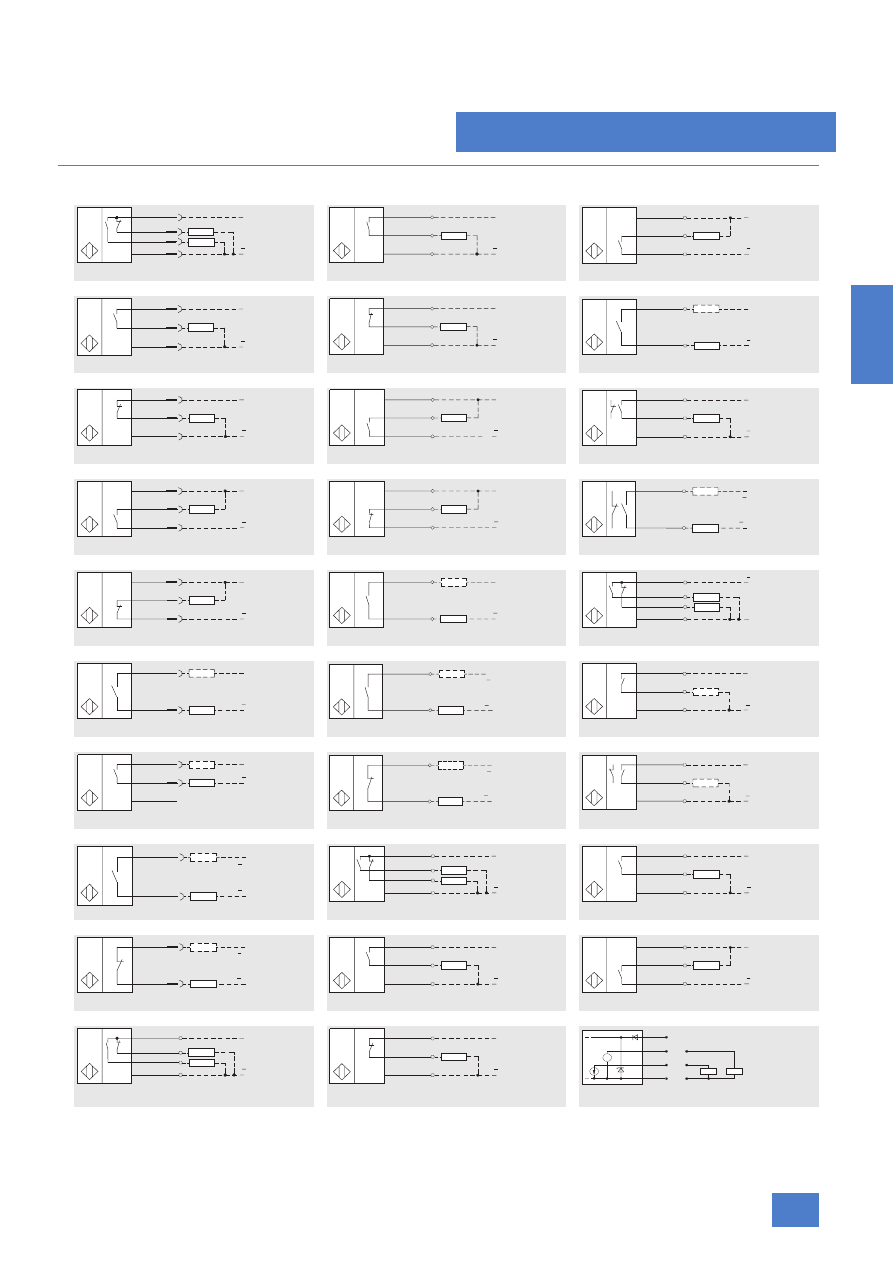
■
Circuit diagrams
Fig. 1
Fig. 11
Fig. 21
Fig. 2
Fig. 12
Fig. 22
Fig. 3
Fig. 13
Fig. 23
Fig. 4
Fig. 14
Fig. 24
Fig. 5
Fig. 15
Fig. 25
Fig. 6
Fig. 16
Fig. 26
Fig. 7
Fig. 17
Fig. 27
Fig. 8
Fig. 18
Fig. 28
Fig. 9
Fig. 19
Fig. 29
Fig. 10
Fig. 20
Fig. 30
Abbreviations for color identification of the con-
nection cables according to IEC 60757:
BK = black
BN = brown
BU = blue
WH = white
1
2
4
3
L+
L
NSD00642
NO+NC
I
L+
L
NSD00652a
NO
BN
BK
BU
I
1
2/4
3
L+
L
NO
NSD00662
I
1
4
3
L+
L
NO
NSD00643
I
NC
NSD00653
BN
BK
BU
L+
L
I
1
4
L+
L
NO
NSD00663
I
1
2
3
L+
L
NC
NSD00644
I
NO
NSD00654
BN
BK
BU
L+
L
I
1
2/4
3
L+
L
NC NO
NSD00664
I
1
4
3
L+
L
NO
NSD00645
I
NC
NSD00655
BN
BK
BU
L+
L
I
1/3
2/4
L1/L+
NC NO
NSD00665
(N/L )
N/L
(L1/L+)
I
1
2
3
L+
L
NC
NSD00646
I
NO
NSD00656
BN
BU
L+
L
I
3
4
2
1
L+
L
NO+NC
NSD00666
I
1
4
L+
L
NO
NSD00647
I
NO
NSD00657
BK
BK
L1/L+
N/L
(N/L )
(L1/L+)
I
1/3
X
2/4
L+
L
NSD00667
NO
I
1
4
3
L+
L
NO
NSD00648
I
NC
NSD00658
BK
BK
L1/L+
N/L
(N/L )
(L1/L+)
I
1/3
X
2/4
L+
L
NSD00668
NC NO
I
3
4
L1/L+
NO
N/L
N/L
L1/L+
I
1
4
2
3
L+
L
NO+NC
NSD00659
I
1
4
3
L+
L
NO
NSD01167
I
1
2
NC
NSD00650
L1/L+
N/L
L1/L+
N/L
I
1
2/4
3
L+
L
NO
NSD00660
I
1
4
3
L+
L
NO
NSD01168
I
L
L+
NSD00651
NO+NC
WH
BN
BK
BU
I
1
2/4
3
L+
L
NC
NSD00661
I
R
L2
R
L1
NSD00669
+U
B
BN
BK
WH
BU
A1
A2
0 V
Inductive proximity switches
Introduction
2/118
Siemens FS 10 · 2007
2
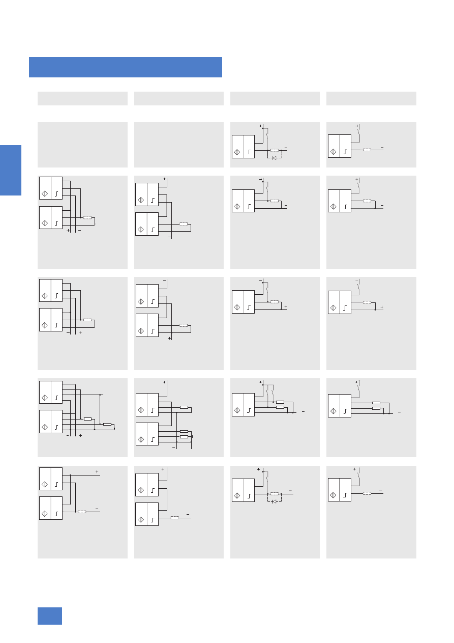
Connection examples
U
b
= operating voltage
U
c
= minimum operating voltage of load
n = number of proximity switches
U
min
= minimum permissible operating voltage
1) The power-up delay of the sensors must be considered when
determining the switching times.
Abbreviations for color identification of the connection cables according
to IEC 60757:
BK = black
BN = brown
BU = blue
WH = white
Parallel connection
Series connection
1
)
Parallel connection with 1 contact
(NO or NC)
Series connection with 1 contact
(NO or NC)
1
)
DC version
2-wire proximity switches, for PLCs
Not possible since the total of all
proximity switch off-state currents
must be smaller than the holding
current of the load
Not possible since
n ≤
U
b
SPS: 24 V
3-wire proximity switches, pnp
n ≤
+ 1
U
c
= U
b
– (n · 2.5 V)
Other connections are not
permissible.
3-wire proximity switches, npn
n ≤
+ 1
U
c
= U
b
– (n · 2.5 V)
4-wire proximity switches, pnp
AC/DC version
The total of all proximity switch
residual currents must be smaller
than the holding current of the load
n ≤
U
c
= U
b
– (n · 8 V)
With DC voltage operation, a diode
must be connected in parallel to the
primarily inductive load.
U
b
15 V
–
8 V
-------------------
NSD00671
BN
BU
L
L
I
NSD00670
BN
BU
L
L
I
NSD00672
BK
BU
L
L
BN
BK
BU
I
I
NSD00673
BN
BK
BU
L
L
BN
BK
BU
I
I
U
b
U
min
–
2,5 V
--------------------
NSD00675
L
BN
BK
BU
L
I
NSD00674
L
BN
BK
BU
L
I
NSD00676
BU
BK
BN
L
L
BU
BK
BN
I
I
NSD00677
BU
BK
BN
L
L
BU
BK
BN
I
I
U
b
U
min
–
2,5 V
--------------------
NSD00679
L
BU
BK
BN
L
I
NSD00678
L
BU
BK
BN
L
I
NSD01187
L
L
BN
BK
I
I
BU
BN
BK
WH
BU
WH
NSD01188
BN
BK
I
I
BU
BN
BK
WH
BU
WH
L
L
I
BN
BK
WH
BU
NSD01190
L
L
I
BN
BK
WH
BU
NSD01189
L
L
NSD00680
BK
BK
BK
BK
N(L )
L1(L )
I
I
NSD00681
BK
BK
BK
BK
N(L )
L1(L )
I
I
U
b
20 V
---------
NSD00683
BK
BK
L1(L )
N(L )
I
NSD00682
BK
BK
N(L )
L1(L )
I
Inductive proximity switches
Introduction
2/119
Siemens FS 10 · 2007
2
■
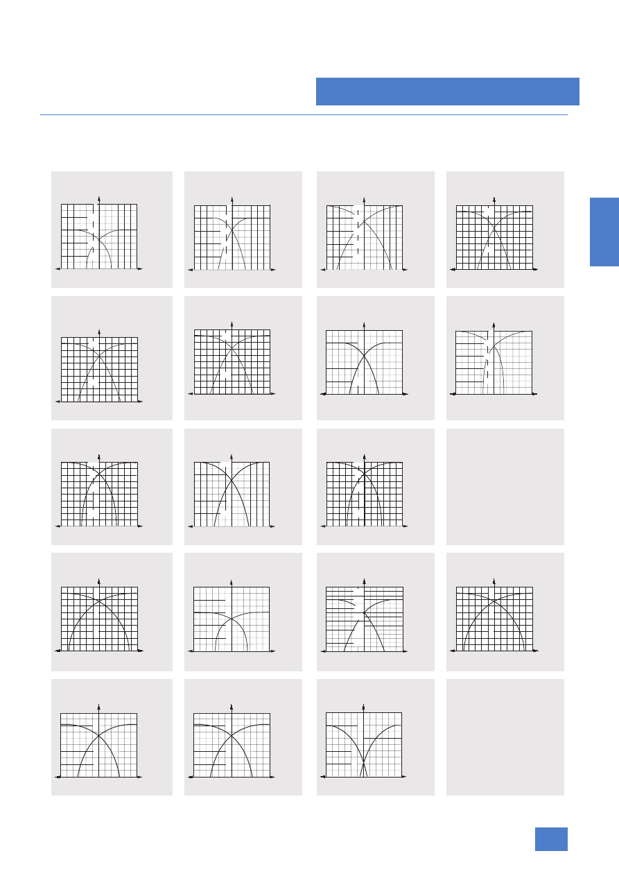
Characteristics
Response curves
The response curves are determined using standard targets
according to EN 60947-5-2.
Operating distance 0.6 mm (normal)
3RG46 03, 3RG46 00, 3RG4610
Operating distance 0.8 mm (nor-
mal) 3RG 46 .0, 3RG 46 36
Operating distance 1 mm (normal)
3RG40 11
Operating distance 1.5 mm (nor-
mal) 3RG40 ..–...33 (Shorty)
Operating distance 1.5 mm (normal)
3RG40 ..–...05, 3RG46 01,
3RG46 11, 3RG46 37
Operating distance 1.5 mm
(U BERO) 3RG46 11
Operating distance 2 mm (normal)
3RG40 12, 3RG40 52, 3RG40 7.
Operating distance 2 mm (extra
duty) 3RG41 11
Operating distance 2.5 mm (normal)
3RG40 21, 3RG40 60
Operating distance 2.5 mm
(normal) 3RG40 72
Operating distance 2.5 mm (extra
duty) 3RG46 02, 3RG46 11
Operating distance 3 mm (extra
duty) 3RG46 11
Operating distance 3 mm (extra
duty) 3RG46 02, 3RG46 37
Operating distance 3 mm
(U BERO) 3RG46 12
Operating distance 3 mm
(pressure-resistant) 3RG46 52
Operating distance 4 mm (normal)
3RG40 22, 3RG40 62
Operating distance 4 mm
(extra duty) 3RG41 12
Operating distance 4 mm
(U BERO) 3RG46 21
y
mm
mm
mm
0,8
1
0
1
NSD00301
-x
+x
0,6
0,2
1
0,5
1,5
1,5
0,5
0,4
y
mm
mm
mm
0,8
2
1
0
1
NSD00303
-x
+x 2
0,6
0,4
0,2
1
y
mm
mm
2
1
0
1
NSD00318
-x
+x 2
0,4
0,2
1,0
0,8
0,6
mm
y
mm
mm
mm
1,5
0,5
1
3
1
0
2
1
NSD00330
-x 2
+x 3
mm
mm
mm
1,5
0,5
1
3
1
0
2
1
NSD00331
-x 2
+x 3
y
mm
mm
mm
1,5
0,5
1
3
1
0
2
1
NSD00331
-x 2
+x 3
y
y
mm
-x
+x
2
0,5
1
4
2
0
2
4
NSD00362
mm
mm
y
mm
-x
+x
0,4
2
4
2
0
2
4
NSD00355
0,8
1,2
1,6
mm
mm
y
mm
mm
mm
2
4
0
4
NSD00390
-x
+x
2
1
0,5
2,5
2
1,5
y
mm
mm
mm
2
4
0
4
NSD00401
-x
+x
2
1
0,5
2,5
2
y
mm
mm
mm
2
4
0
4
NSD00390
-x
+x
2
1
0,5
2,5
2
1,5
y
mm
mm
mm
1
3
0
3
NSD00394
-x
+x
2
1
3
2
2
1
0
2
2
-x
+x
mm
mm
mm
y
4
4
1
2
3
4
6
6
NSD00396
N
S
D
0
0
4
1
5
y
mm
-x
+x
3,5
3,0
1,5
1,0
0,5
4
2
4
2
0
2,0
2,5
mm
mm
y
mm
mm
mm
1
3
0
3
NSD00394
-x
+x
2
1
3
2
2
1
y
mm
-x
mm
1
2
4
2
0
4
2
NSD00422
4
+x
mm
mm
y
mm
-x
mm
1
2
4
2
0
4
2
NSD00422
4
+x
mm
mm
y
mm
-x
mm
1
2
4
2
0
4
2
NSD0_00426
4
+x
mm
mm
3
Inductive proximity switches
Introduction
2/120
Siemens FS 10 · 2007
2
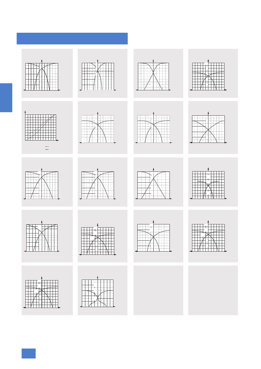
Operating distance 5 mm (normal)
3RG40 13, 3RG40 53
Operating distance 5 mm (normal)
3RG40 82
Operating distance 5 mm
(U BERO) 3RG46 13
Operating distance 6 mm (extra
duty) 3RG46 21, 3RG46 12
Operating distance 0 ... 6 mm
(analog) 3RG46 12
Operating distance 8 mm (normal)
3RG40 23, 3RG40 63
Operating distance 8 mm (extra
duty) 3RG41 13
Operating distance 8 mm
(U BERO) 3RG46 22
Operating distance 10 mm (normal)
3RG40 14, 3RG40 54, 3RG46 25
Operating distance 10 mm (extra
duty) 3RG46 22
Operating distance 10 mm
(U BERO) 3RG46 14
Operating distance 12 mm
(extra duty) 3RG46 13
Operating distance 12 mm
(U BERO) 3RG46 23
Operating distance 15 mm
(normal)
3RG40 24, 3RG40 31, 3RG 40 64
Operating distance 15 mm
(normal) 3RG40 30, 3RG40 34
Operating distance 15 mm (nor-
mal) 3RG40 38
Operating distance 15 mm
(extra duty)
3RG46 12
Operating distance 15 mm
(U BERO) 3RG46 34, 3RG46 38
y
mm
-x
+x
5
4
3
2
1
8
4
0
4
8
NSD00450
mm
mm
y
mm
mm
mm
8
0
8
NSD00474
-x
+x
1
5
4
4
2
4
3
NSD00462
y
mm
-x
+x
5
4
3
2
1
10
4
0
8 6
2
10
4
8
6
2
mm
mm
y
mm
mm
mm
4
8
0
8
NSD00482
-x
+x
4
4
2
10
8
6
y
mm
5
1
2
1
2
3
5
4
NSD00487
4
3
S mm
U
A
V
I
A
mA
y
mm
-x
+x
10
2
4
8
4
0
8
4
NSD00499
8
6
mm
mm
y
mm
-x
+x
10
2
4
8
4
0
8
4
NSD00499
8
6
mm
mm
10
4
NSD00491
y
mm
-x
+x
8
6
2
4
2
4
2
0
mm
mm
mm
-x
+x
10
8
6
4
2
10
5
10
5
0
NSD00516
y
mm
mm
mm
-x
+x
10
8
6
4
2
10
5
10
5
0
NSD00516
y
mm
mm
NSD00531
10
4
y
mm
-x
+x
8
6
2
8
4
8
4
0
12
12
mm
mm
y
mm
-x
+x
20
4
8
20 10
0
20
10
NSD00542
16
12
mm
mm
NSD00540
y
mm
-x
+x
12
4
6
2
10
4
0
8 6
2
10
4
8
6
2
8
10
mm
mm
y
mm
-x
+x
NSD0547
mm
mm
0
5
10
5
10
4
8
12
16
20
y
mm
-x
+x
20
16
8
4
NSD00562
16
8
16
8
0
mm
mm
y
mm
-x
+x
NSD01170
mm
mm
0
8
16
8
16
4
8
12
16
20
y
mm
-x
+x
NSD0547
mm
mm
0
5
10
5
10
4
8
12
16
20
NSD00568
5
15
20
y
mm
-x
+x
10
4
0
8 6
2
10
4
8
6
2
25
10
mm
mm
Inductive proximity switches
Introduction
2/121
Siemens FS 10 · 2007
2
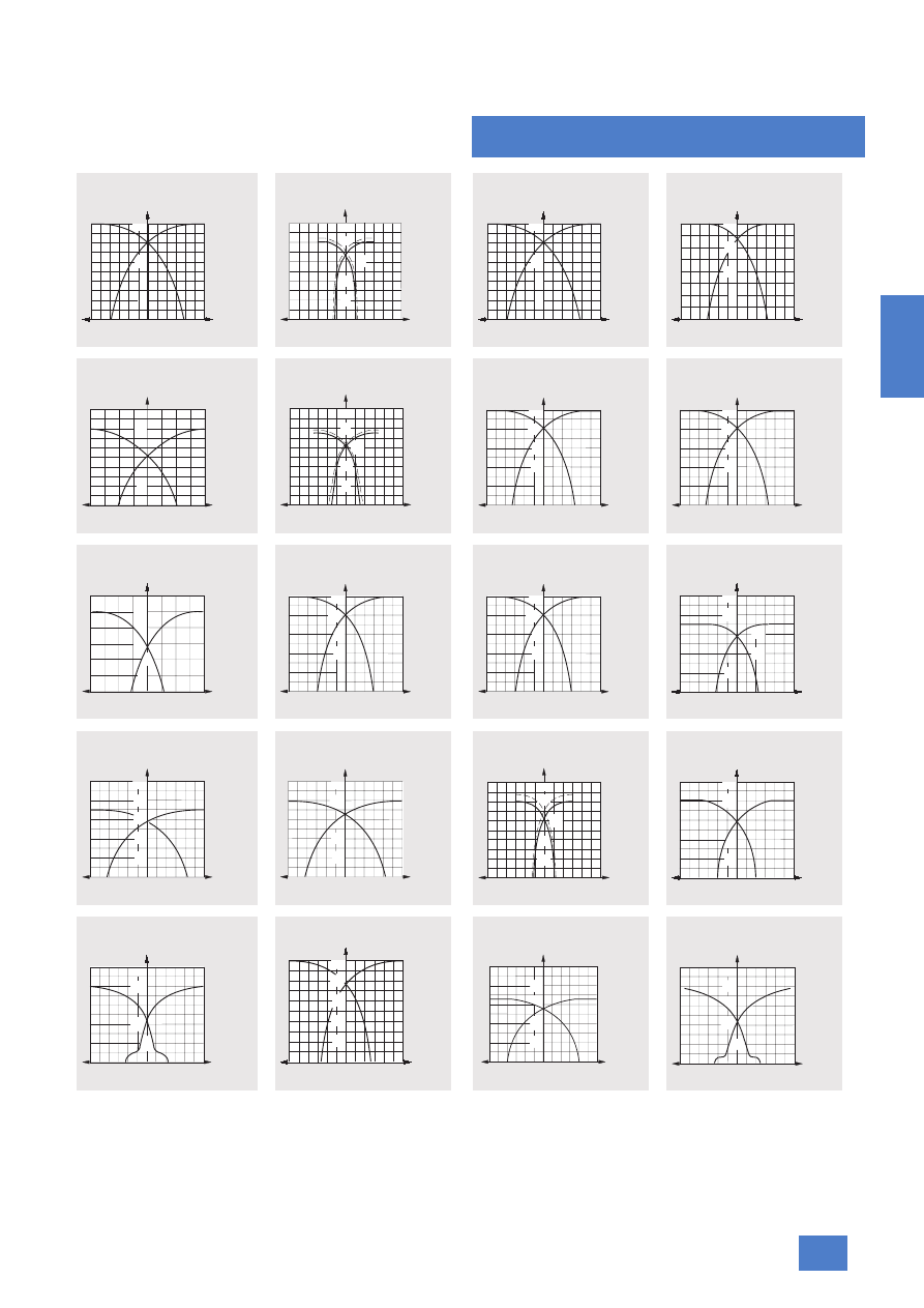
Operating distance 20 mm (normal)
3RG40 41, 3RG46 26
Operating distance 20 mm
(extra duty) 3RG46 23
Operating distance 20 mm (extra
duty) 3RG 41 34, 3RG46 38
Operating distance 20 mm
(extra duty) 3RG41 38
Operating distance 20 mm
(U BERO) 3RG46 12
Operating distance 22 mm
(extra duty) 3RG46 14
Operating distance 25 mm
(normal) 3RG40 32
Operating distance 25 mm (extra
duty) 3RG41 31, 3RG41 41
Operating distance 25 mm
(U BERO) 3RG46 44, 3RG46 48
Operating distance 30 mm
(normal) 3RG 40 33, 3RG40 42
Operating distance 30 mm
(extra duty) 3RG41 44
Operating distance 35 mm
(extra duty) 3RG41 48
Operating distance 35 mm
(U BERO) 3RG46 48
Operating distance 40 mm
(normal) 3RG 40 33, 3RG40 43
Operating distance 40 mm
(extra duty) 3RG46 24
Operating distance 40 mm
(extra duty) 3RG41 41
Operating distance 40 mm
(U BERO) 3RG46 44
Operating distance 50 mm
(extra duty) 3RG41 42
Operating distance 65 mm
(extra duty) 3RG41 43
Operating distance 75 mm
(U BERO) 3RG46 43
y
mm
mm
8
16
0
16
NSD00581
-x
+x
8
8
4
20
12
mm
y
mm
-x
+x
25
5
40 20
0
40
20
NSD00573
20
15
10
5 4 3 2 1
mm
mm
y
mm
mm
8
16
0
16
NSD00581
-x
+x
8
8
4
20
12
mm
y
mm
mm
10
20
NSD01171
-x
+x
mm
0
10 20
5
10
15
20
25
NSD00577
y
mm
-x
+x
8 4
8
4
0
12
12
5
10
15
20
mm
mm
y
mm
-x
+x
30
6
40 20
0
40
20
NSD00592
24
18
12
mm
mm
y
mm
-x
+x
25
5
10
20 10
0
20
10
NSD00594
15
20
mm
mm
y
mm
-x
+x
25
5
10
20 10
0
20
10
NSD00594
15
20
mm
mm
25
NSD00598
y
mm
-x
+x
20 10
20
10
0
30
30
20
10
5
15
30
mm
mm
y
mm
mm
+x
30
6
12
30 15
0
30
15
NSD00604
18
24
-x
mm
y
mm
mm
+x
30
6
12
30 15
0
30
15
NSD00604
18
24
-x
mm
y
mm
-x
+x
50
10
20
40 20
0
40
20
NSD01172
40
mm
mm
30
y
mm
-x
+x
50
10
20
30
30 15
0
30
15
NSD00612
40
mm
mm
y
mm
-x
+x
50
10
20
30
30 15
0
30
15
NSD00626
40
mm
mm
y
mm
-x
+x
50
10
80 40
0
80
40
NSD00614
40
30
20
mm
mm
y
mm
-x
+x
50
10
20
40 20
0
40
20
NSD00620
40
mm
mm
y
mm
-x
+x
50
10
20
40 20
0
40
20
40
NSD00630
mm
mm
mm
mm
mm
20
40
0
40
N
S
D
0
0
6
3
5
a
-x
+x
20
20
10
50
50
30
10
10
30
50
40
30
0
-x
+x
mm
mm
mm
y
20
40
80
60
20
40
60
20 40 60
NSD00638
NSD00640
y
mm
-x
+x
80
80 40
80
40
0
100
60
40
20
mm
mm
Inductive proximity switches
Introduction
2/122
Siemens FS 10 · 2007
2
■
Further information
Active surface
The active surface of an inductive proximity switch is the surface
through which an electromagnetic field is emitted (IEC).
The corresponding activation element (target) is moved toward
this surface to trigger a switching process.
Axial approach
Axial approaching of the target is where its center point is lo-
cated in the reference axis (IEC).
Axial distance to target ∆x
Distance between the actuating element and the proximity
switch axis z at the response point A.
Current input
The current input is understood to be the current consumption of
the proximity switch required to operate the oscillator, amplifier,
etc. It does not include the current flowing through the load.
The no-load current I
0
is the current drawn from the power sup-
ply without a load being connected.
Differential travel H
Distance between the switching points when the target ap-
proaches or is removed from the proximity switch (IEC).
The differential travel causes a defined switching response for
the devices. The switching distance always refers to the switch-
on point.
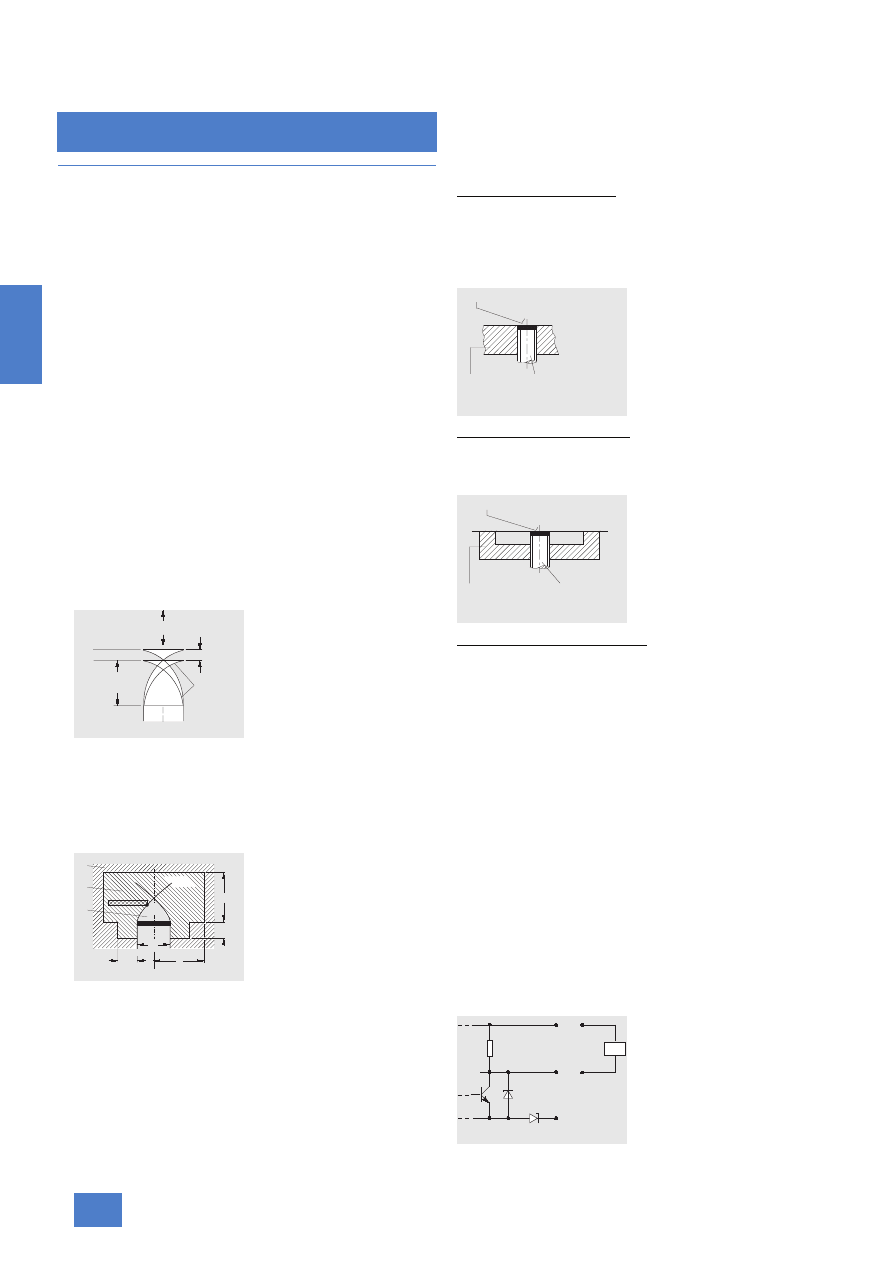
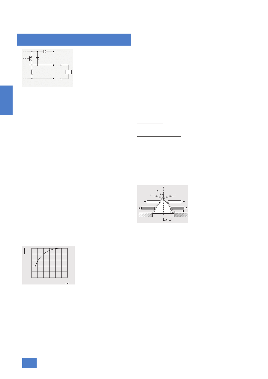
Free zone
Range around the proximity switch which must be kept free of
materials which interfere with the characteristic features of the
switch (IEC).
The volume of the free zone is defined by the dimensions r, c and
w, g (see graphic).
Ak
Response characteristic
A
Response point
c, g
Height points of the transition zone
d
Diameter of the proximity switch
Q
Active area
r
Radius of the free zone
w
Installed state
z
Reference axis
Z
B
Attenuation zone
Z
F
Free zone
Z
J
Inactive zone
Installation
Shielded proximity switches
A proximity switch can be shielded if any attenuating material
(metal) can be attached around the active surface without influ-
encing the characteristic features (IEC).
To ensure perfect functioning, a gap should be left in front of the
active surface.
Unshielded proximity switches
A proximity switch cannot be shielded if a certain free zone is re-
quired around its active surface in order to retain the character-
istic features (IEC).
Semi-shielded proximity switches
A proximity switch that is semi-shielded also requires a certain
free zone. However, flush mounting is permissible in non-atten-
uating materials.
Magnetic fields
Permanent magnetic fields and low-frequency alternating fields
do not generally influence the function of the proximity switches.
Strong fields may saturate the ferrite core of the switch and thus
increase the operating distance or switch the device. On the
other hand, damage is not probable.
High-frequency fields with frequencies of several hundred kHz
can considerably interfere with the function (operating fre-
quency of the sensors). Shielding is recommended in the event
of difficulties with interference fields.
Non-equivalence
The 4-wire proximity switches have two outputs:
• A
1
with NO function and
• A
2
with NC function.
npn connection
The output stage contains an npn transistor which connects the
load to the negative operating voltage (0 V). The load is con-
nected between the output and the positive operating voltage
(+U
B
).
NSD01053
Switch-off point
Switch-on point
Operating dis-
tance s
Response
curves
Differential
travel
Direction of movement
w
d
Q
Ak
A
Z
F
Z
J
Z
B
r
c
g
z
NSD01061
NSD01060
Metal
BERO
Sensing face
Proximity switch
NSD01062
Metal
BERO
Sensing face
Proximity switch
NSD01049
+
U
A
B
0 V
R
L
Load

Inductive proximity switches
Introduction
2/123
Siemens FS 10 · 2007
2
Operating temperature
The specified operating temperature range must not be ex-
ceeded. The proximity switch could then be damaged, and the
operating response is undefined.
Operating distance
The operating distance is the distance at which a change in sig-
nal is caused at the output when the target approaches the ac-
tive surface along the reference axis (IEC).
Measurement of the operating distance is carried out according
to IEC 60947-5-2 using a standard target and axial approach.
Rated operating distance s
n
The rated operating distance is a conventional variable for defin-
ing the operating distances. Neither specimen scatter nor
changes resulting from external influences such as voltage or
temperature are taken into account (IEC).
This operating distance applies when using the standard target
according to IEC 60947-5-2
.
Reduction factors must be consid-
ered if the material and/or size of the target differ from those of
the standard target.
Real operating distance s
r
Operating distance of a particular proximity switch measured at
defined temperature, voltage and mounting conditions (IEC).
This is the operating distance for a particular switch measured
according to IEC 60947-5-2. The manufacturing tolerance is
10 %:
0.9 s
n
< s
r
< 1.1 s
n
Usable operating distance s
u
Operating distance of a particular proximity switch measured
under defined conditions (IEC).
This includes the additionally expected deviations caused by
the variations in temperature and operating voltage within the
specified ranges.
The usable operating distance is between 90 % and 110 % of
the real operating distance. This results in the following for a re-
liable design:
0.81 s
n
< s
u
< 1.21 s
n
Ensured operating distance (actuation distance) s
a
Distance from the active surface at which actuation of the prox-
imity switch is ensured under defined conditions (IEC).
The ensured operating distance is between zero and the bottom
value of the useful operating distance:
0 < s
a
< 0.81 s
n
s
a
Working distance
s
n
Rated operating distance
s
r
Real operating distance
s
min
min. useful operating distance s
u
(= working distance s
a
)
s
max
max. useful operating distance s
u
Operational voltage
The operating voltage is specified including 10 % residual rip-
ple.
Output
The proximity switches are available with different output con-
nections.
2-wire, DC or AC/DC, load connected in series with the proximity switch
3-wire, DC, pnp, load connected between A and L–
3-wire, DC, npn, load connected between A and L+
4-wire, antivalent, DC, load connected between A
1
, A
2
and L–
Output resistance
The proximity switches have a built-in output resistance so that
the output voltage can follow the switching status even without
an external load. A load resistance must be connected when op-
erating with high switching frequencies (to reduce the electric
time constant).
Parallel connection
Parallel connection of proximity switches to implement logical
functions is possible with 3-wire and 4-wire proximity switches
without problem, but not with 2-wire proximity switches.
Please note:
• The power consumption increases.
• Leakage currents add up so that an impermissible voltage
drop may occur at the load even in the off state.
See graphics, Seite 118.
pnp connection
The output stage contains a pnp transistor which connects the
load to the positive operating voltage (+U
B
). The load is con-
nected between the output and the negative operating voltage
(0 V).
NSD01063
120%
100%
80%
0%
s
n
s
r
-10%
+10%
min
s
rmax
s
min
-10%
+10%
s
max
s s
+ 20%
N
n
s
a
BERO
Sensing
face
NSD01055
L+
L-
I
NSD01057
L+
L-
A
I
NSD01056
L+
L-
A
I
NSD01058
L+
L-
A2
A1
I
Inductive proximity switches
Introduction
2/124
Siemens FS 10 · 2007
2
Power-up delay t
v
Duration between switching on the power supply and the begin-
ning of the proximity switch's operational readiness (IEC).
Power supply units
Single-phase power supply units must be smoothed with at least
1000 µF/A. For noise suppression reasons, this measure is also
necessary with three-phase power supply units.
Programming
Selection of NO or NC function using slide switch in bottom part
of enclosure or plug-in jumper in the electronics base. Only with
certain cubic proximity switches.
Proximity switch lexicon
Some of the terms are defined in IEC 60947-5-2.
Rated operational current I
e
(output current)
The sensors are designed for a specific maximum output cur-
rent. If this current is exceeded, even briefly, the built-in overload
protection will be activated. Incandescent lamps, capacitors
and other strongly capacitive loads (e.g. long leads) have ef-
fects similar to an overload.
Reduction factors
The specified operating distance s refers to exactly defined
measuring conditions (see operating distance). Reduced oper-
ating distances usually result with other arrangements. The re-
duction factors (see Technical specifications) are only approxi-
mate values. Deviations may result depending on different alloys
and the type.
Influence of geometry
If a smaller target is used than the standard target defined in
IEC 60947-5-2, the operating distance must be corrected by a
reduction factor.
Reference axis z
Axis running perpendicular to the active surface and through its
center (IEC).
Residual voltage
The residual voltage is the voltage measured across the load
with the output disabled.
Residual current i
r
The residual current is the current which flows in the load circuit
of the proximity switch in the disabled condition (IEC).
It is used to retain the function, and must primarily be observed
with parallel connections.
Residual ripple
σ
The maximum value of the residual ripple from peak to peak
must not exceed 10 % of the rated voltage U
n
. The switching re-
sponse may be undefined if the residual ripple is large. Correc-
tion is possible using a larger smoothing capacitor or a regu-
lated power supply.
Release point B
The position, e.g. in the attenuation zone, at which the bottom
rear edge of the actuating element is located at the moment the
signal changes when removing.
Resistance to oil
The proximity switches with degree of protection IP67 are not
suitable for permanent operation in an environment containing
oil. The following must therefore be observed:
Lubricating oils
Usually present no problem.
Hydraulic oils, cutting oils
These attack most plastics. In particular, the PVC lines become
discolored and brittle.
Measures: avoid contact with these liquids if possible, especially
on the active surface.
Response curve
The line on which all response points A for a proximity switch can
be found. The curve has been determined using the standard
target. The sensor-related characteristics can be obtained from
it. The proximity switch axis z coincides with the y axis.
Ak
Response characteristic
A
Response point
B
Release point
H
Differential travel
s
Operating distance
x
Direction of motion
∆
x
Triggering distance
y
Distance to proximity switch
z
Reference axis
Repeat accuracy R
The repeat accuracy is the change in the real operating distance
s
r
at defined conditions (IEC).
The repeat accuracy is measured over a period of 8 hours at an
ambient temperature of 23 °C (± 5 °C), any relative humidity
within the specified range, and a defined supply voltage.
The difference between any two measurements must not exceed
10 % of the real operating distance s
r
. The repeat accuracy is
usually far better in the case of measurements immediately fol-
lowing one another.
Response delay t
A
The response delay is the duration which the switching element
requires for response when the target enters or leaves the sens-
ing range (IEC).
The value is measured at s = 0.5 × s
n
.
NSD01050
+
U
R
A
0 V
L
B
Load
1,0
1,2
1,0
0,8
0,6
0,4
0,2
0
0,8
0,6
0,4
0,2
0
NSD01054
Relative side length of target
R
e
d
u
c
tio
n
f
a
c
to
r
NSD0 010
y z
x
x
x
x
Ak
B
A
B
H
s
x
x
A
Sensing face

Inductive proximity switches
Introduction
2/125
Siemens FS 10 · 2007
2
Response point A
The position of the actuating element when the signal is output.
The reference point is the bottom front edge of the actuating el-
ement.
Series connection
See graphics, Seite 118.
Smallest operating current I
m
(minimum load current)
The current required to retain the conductivity of the switching
elements in the ON state (IEC). This applies to 2-wire proximity
switches.
Standard target
The standard target is a defined part used for comparison mea-
surements of the operating distances and sensing ranges (IEC).
Material of standard target: St 37, 1 mm thick
Dimensions of square standard target: the side length is equal to
• the diameter of the inscribed circle on the active surface of the
proximity switch or
• three times the rated operating distance s
n
if 3 × s
n
is greater
than the diameter of the inscribed circle.
Switching element function
NO function
An NO function results in a flow of load current when the target
is sensed, and no flow of the load current when the target is not
sensed (IEC).
NC function
An NC function results in no flow of load current when the target
is sensed, and a flow of load current when the target is not
sensed (IEC).
Switching frequency f
Number of switching operations of a proximity switch within a
defined time interval (IEC).
The switching frequency is the maximum possible switching rate
between the damped and non-damped statuses at which the
output circuit still delivers a defined signal sequence corre-
sponding to the activation.
Switching frequency s
a
See under operating distances.
Target (actuating element)
Parts made of metal with which proximity switches are actuated
in service.
Form, material and dimensions influence the response charac-
teristic of the proximity switch (see reduction factors).
The specified rated operating distances s
n
were determined us-
ing the minimum surface defined in the standard (see character-
istic). The usable operating distance s
u
is reduced if the surface
is less than the minimum.
Temperature drift
The specified operating distances refer to an ambient tempera-
ture of 20 °C. Within the permissible temperature range of –25 to
+70 °C, the operating distance varies by max. ±10 % compared
to the value at 20 °C.
The temperature of the target alone has practically no influence
on the operating distance.
Tightening torque
Excessive tightening of the nuts could mechanically damage the
proximity switches. The maximum permissible torques are spec-
ified in the Technical specifications.
SIt specifies the maximum permissible number of pulses per
second at a constant pulse: Pause = 1 : 2 and half the rated op-
erating distance s
n
. The measurement is carried out according
to IEC 60947-5-2.
Voltage drop
A voltage drop (dependent on the current) occurs across the
output transistor in the conductive state; the output voltage does
not quite reach the associated operating voltage (to be particu-
larly observed with a series connection and electronic inputs).
Welding-resistant
Sensors which can be used in strong magnetic fields, e.g. dur-
ing arc welding, or in fields of electrolysis plants.
The maximum permissible value is specified for specially se-
lected sensors, e.g. U BERO.
s
/ 2
n
m
2 m
NSD01052
Proximity
switch
Non-conductive
material
Disc
Target
Wyszukiwarka
Podobne podstrony:
Badanie czujnika indukcyjnego, Czujnik indukcyjny, Kaczor Rafał
Czujniki indukc
Badanie czujnika indukcyjnego, czujnik indukcy, POLITECHNIKA RADOMSKA
Badanie czujnika indukcyjnego i hala
as czujniki indukcyjne
Czujniki indukc
Czujniki indukcyjne
RIKO PS0801 NP karta katalogowa czujnik indukcyjny
Badanie indukcyjnych i pojemnościowych czujników zbliżeniowych, MECHATRONIKA, IV Semestr, Mikronapęd
Czujniki zbliżeniowe indukcyjne
2004 01 Indukcyjny czujnik zbliżeniowy
02 czujniki, systematyka, zastosowania
czujniki2
Czujniki temperatury cieczy chłodzącej
5 Czujniki Podrecznik PL
Czujniki przemieszczeń kątowych
czujnik cisnienia spalin
więcej podobnych podstron