
Registration Number MT2291
Eligible Parts:
dsPIC30F6010A
INTRODUCTION
The EV Drive team has constructed an inverter using a control board and software based upon
Microchip’s MC-1 development board, using a dsPIC30F6010A and 3 dual IGBT modules with
gate driver boards from Powerex. This project is a 100kW 3-phase inverter developed as an open-
source process, which can be continually improved upon.
All components of the inverter design are “off the shelf” units readily available at many
electronics distributors (Digikey, Mouser, etc). These parts can also be subject to change with the
open-source design being modified to suit a user’s needs or improved by advancing technology.
This facet of the inverter’s design is meant to mesh with an easy application of the system. A user
should be able to easily obtain all components of the inverter (if not purchasing an assembled
system), and once constructed it will be able to power a wide range of AC induction motors. This
means that the user can select a motor that was not originally designed for a vehicle. For our
project we used a motor that was from an elevator.
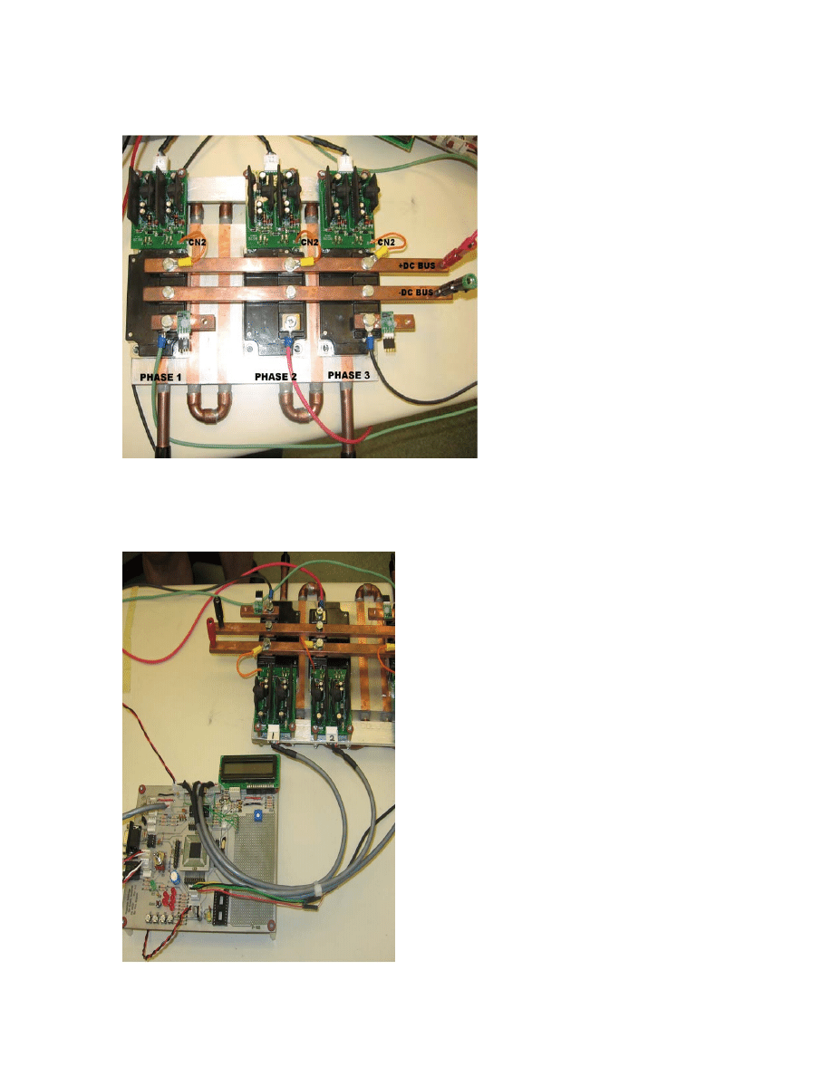
POWER INVERTER
The Powerex CM400DU-12F Insulated Gate Bi-polar Transistors (IGBT) [1] modules and their
companion BG2B gate driver circuits [2] provide a relatively low cost method for generating 3-
phase AC power from DC power. The DC power from the EV battery pack is converted to 3-
phase AC for driving an AC induction motor. We configured each phase of the IGBT module
design with RCD snubber protection (Figure 1) [3]. The gate driver circuit can be seen in the
BG2B application note from Powerex, using 2 VLA106-15242 DC/DC converters and 2
VLA503-01 gate drivers. These gate driver boards are recommended by Powerex for use with
the dual IGBT modules and provide 2500VAC of control signal isolation via high-speed
optocouplers and de-saturation detection to prevent short-circuit conditions on the IGBTs. The
CM400DU-12F modules are rated with a collector-emitter voltage of 600V and continuous
emitter current of 400A with a peak rating of 800A. These modules are also able to provide
switching speeds up to 30kHz; we used 20kHz. The frequency range promotes efficient
operation of the spatial vector modulation (SVM) algorithms used to drive the IGBTs as well as
bringing the switching noise out of audible range.
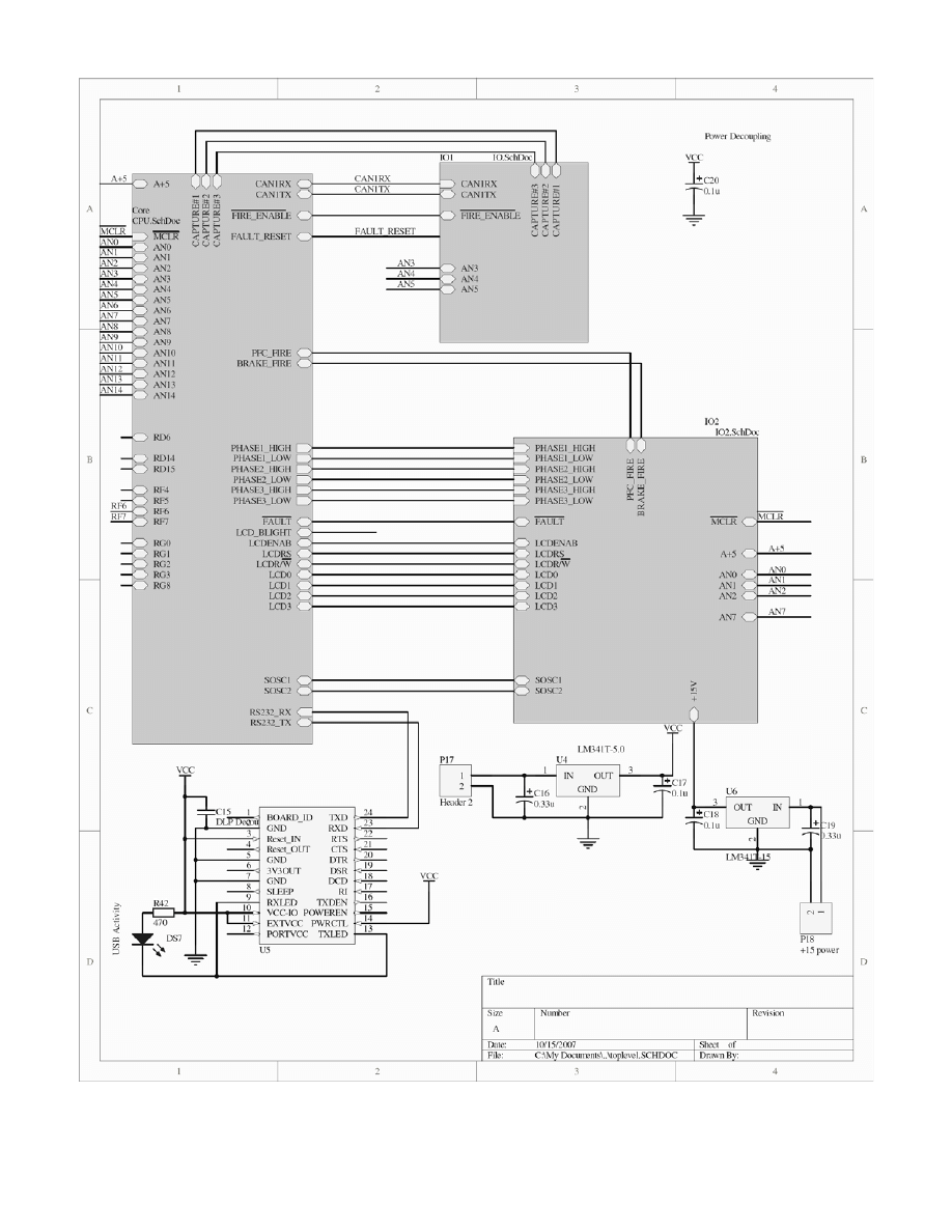
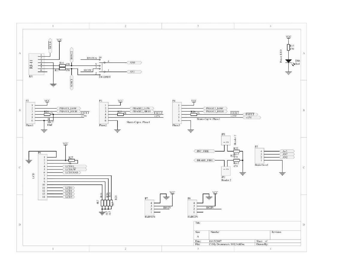
CONTROL BOARD
The control board of the inverter is primarily a stripped down variant of the Microchip MC-1
development board [4]. This was done for code compatibility and to reduce actual development
time. Several simple changes were made to the PCB design. The bias resistors on the gate
drivers were moved to the output of the logic buffer and given the capacity to function as either
pull-up, pull-down, or float depending on the placement of a jumper. Regulators were added to
the board, providing stable +5 and +15 volt sources. Additional decoupling capacitors were
placed in the circuit to reduce the inevitable noise (motor noise, switching noise) that are inherent
to the system.

Registration Number MT2291
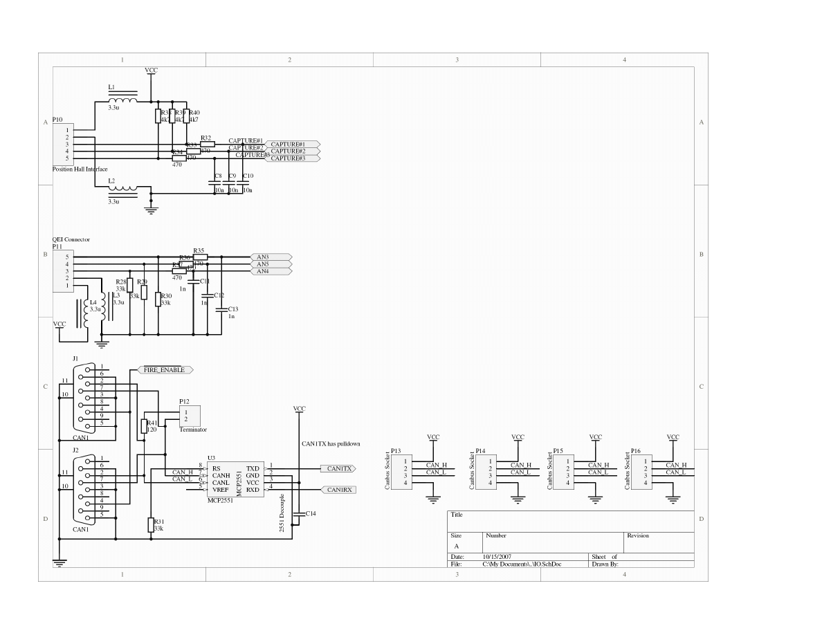
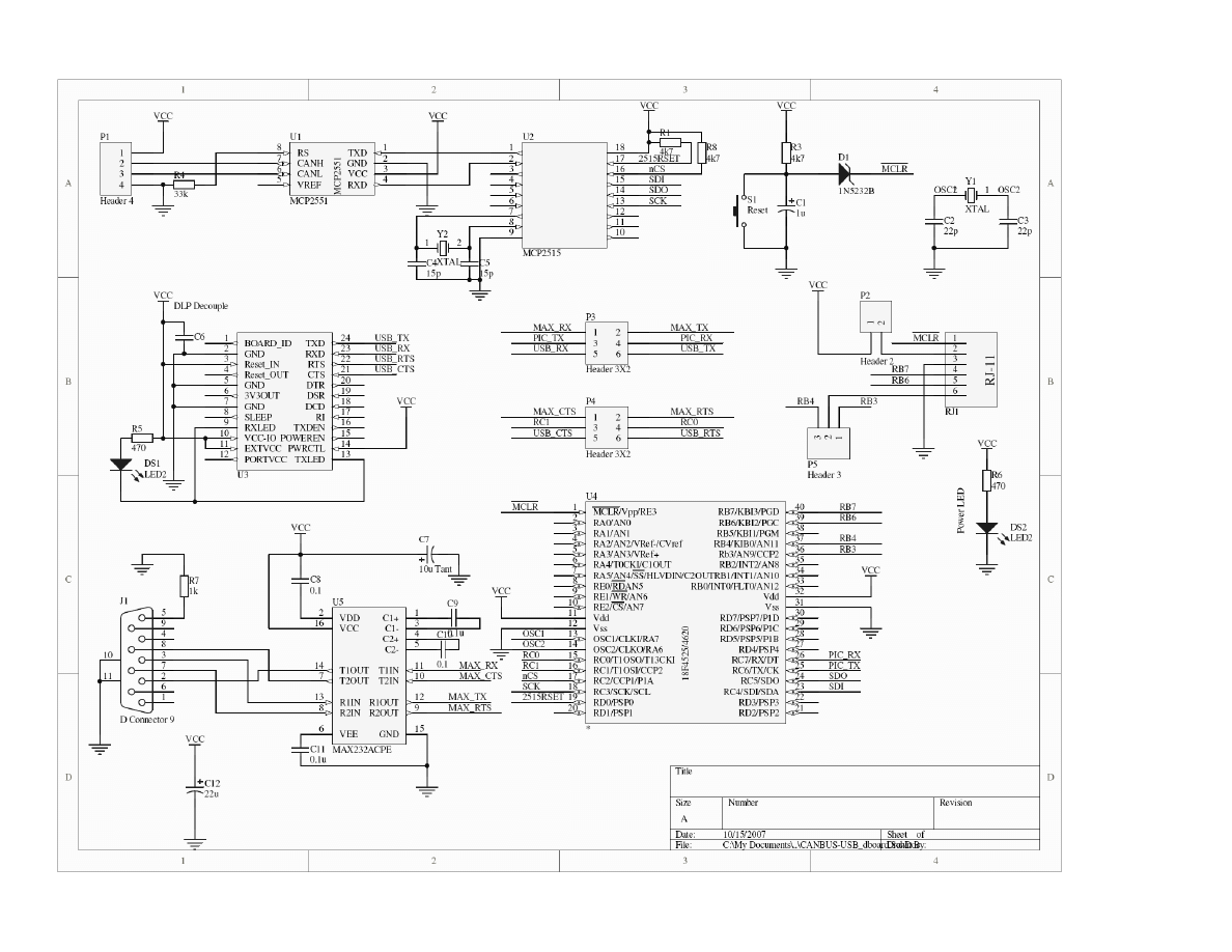
There was a daughter board created to assist in debugging as well as providing an interface to the
LabVIEW application used for motor tuning. The daughter board acts as a bridge between CAN
bus and USB with robust error checking between the two protocols. The daughter board MCU
and the CAN bus controller were left with separate clocks due to the timing sensitivity of the
CAN bus. With some minor modifications, the module could also control an optional LCD
display. The module connects to the main board with a 4-pin connector which also provides
power to the module. Four of these sockets are provided on the main board.
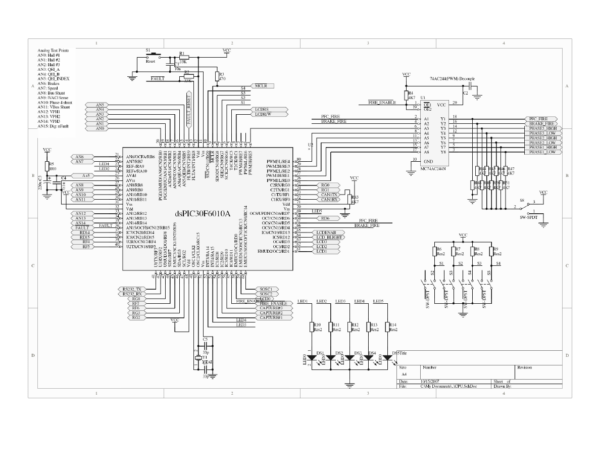
SPACE VECTOR MODULATION
To generate the 3-phase AC power from DC power, the inverter is supplied logic drive signals in
form of a sine-wave PWM called Space Vector Modulation (SVM). The SVM software is based
upon Microchip’s motor control Application Note 908 [5] and is implemented by a
dsPIC30F6010A based control board. This 16-bit dsPIC features 8 PWM outputs, a quadrature
encoder interface (QEI) module and 2 CAN bus modules, making it an optimal MCU for motor
control. A QEI rotary shaft encoder is used to measure motor RPM in our system.
PID TUNING
For our electric vehicle project, we decided to use a squirrel-cage AC induction motor. To uses
this motor for such an application, it is obvious that some tuning of the motor controller is
required. To tune the motor, we developed a LabVIEW application that allows the user to tune
the PID variables then after starting the motor the user can watch the motor response in real-time.
The response of a motor is critical to the overall operation of the EV system. When a new motor
is connected to the motor controller circuit board, the PID parameters must be properly aligned.
If the motor does not seem to respond very well to an input like stepping on the accelerator, there
needs to be alterations to the PID control loops.
CAN BUS / LABVIEW INTERFACE
The Human Machine Interface (HMI) for this project is a LabVIEW 7.1 application built to
communicate to the CAN bus module with “serial over USB” protocol by FTDI. We used the
DLP-USB232M-G integrated module featuring FTDI's FT232BL 2nd generation USB UART [6].
This module was an appropriate choice for development because it can be plugged into a standard
24-pin 0.6in wide DIP socket that is mounted on our daughter board and it could be moved easily
to another board if required. FTDI also developed its USB functions as LabVIEW Virtual
Instruments (VIs) that are called from our HMI, which also made them a good choice for our
application [7]. For message processing on the daughter board, we used a PIC18F4620 [8] with
an external CAN bus controller MCP2515 [9] and transceiver MCP2551 [10]. These CAN bus
control ICs and the MCU are manufactured by Microchip.
CONCLUSION
As the Electric Vehicle becomes a more viable alternative for transportation, this project
will be referenced as one way to accomplish part of the conversion of a gasoline engine
to an electric motor. Currently the main factors in conversion are safety and battery
technology. As these concerns are addressed, an open source project will be a welcome
alternative for those who wish to take on an electric motor modification themselves.
Registration Number MT2291
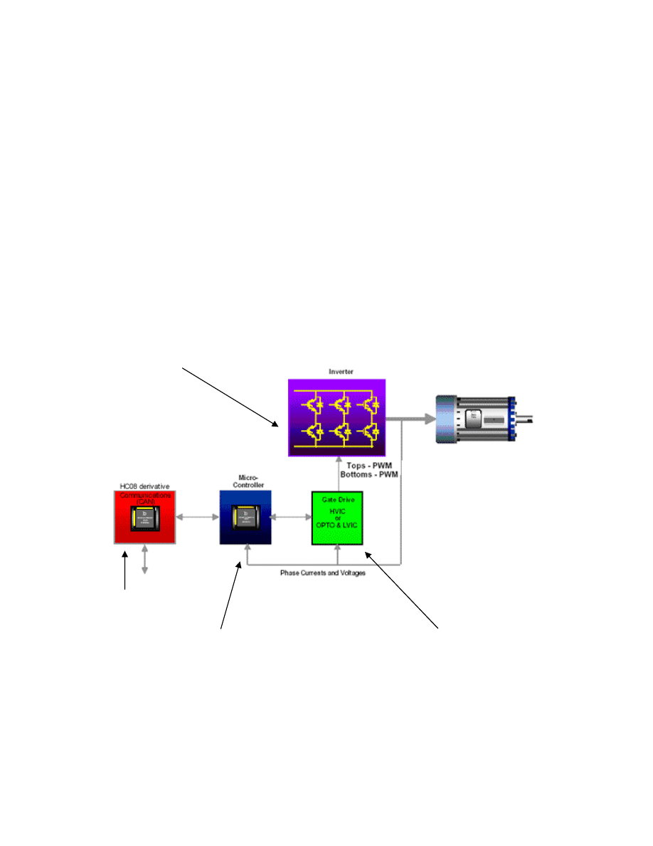
System Block Diagram
As seen below in Figure 2-1, the operation of the electric drive system relies on four
component blocks. “Block 1” is the dsPIC30F6010a microcontroller, which operates the
SVM software to control the optically isolated gate-drive circuit seen in “Block 2.” The
gate-drive circuit forwards the control signals to the 3-phase inverter. The inverter is seen
in “Block 3,” and provides the 3-phase AC voltage and current by converting its’ input
DC voltage to AC and driving the motor. “Block 4” is the diagnostics and
communications block. This block uses CANBUS communications to provide
information to the user about the operation of the inverter and motor. Also, this block is
used for initial setup and tuning of the drive system.
Figure 2-1
Block 3
Block 1
Block 2
Block 4
Registration Number MT2291
Wyszukiwarka
Podobne podstrony:
Abstract MT2291
Abstrakcyjne wyobrażenie elementów systemu komputerowego
Abstrakt, bezpieczeństwo, Infrastruktura krytyczna
Abstrakty z nieorganicznej
ABSTRAKCYJNE TŁO
ABSTRAKCYJNA NASTĘPCZA KONTROLA KONSTYTUCYJNOŚCI PRAWA
Poznajemy oraz tworzymy dzieła abstrakcyjne w pracowni malarskiej - KONSPEKT ZAJĘĆ, szkoła, szkoła p
JIW Abstrakty2
Raki szyjki macicy, MEDYCYNA VI rok, Choroby wewnętrzne, Wywiad + badanie fizykalne, Interna abstrak
ABSTRAKCJA
Abstractions in Power Writing
Abstract78 CDA Do No Harm Handbook, (Collaborative Learning Projects)
Abstrakt stowarzyszenia i fundacje
Abstrakcja w II po XX w, Notatki I i II rok hs, Sztuka współczesna
Abstrakt
Abstrakcja różnicowa
więcej podobnych podstron