
ENVI Tutorial:
Orthorectifying Aerial Photographs
Table of Contents
Tutorial: Orthorectifying Aerial Photgraphs
Overview of This Tutorial
This tutorial gives you a working knowledge of ENVI’s orthorectification capabilities for aerial photographs. It
demonstrates ENVI’s orthorectification capabilities for aerial photographs, but (because of the size of the required
datasets) does not use any hands-on exercises. No data files are required. You should be able to produce similar results
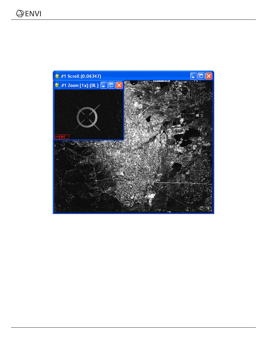
with your own scanned aerial photographs following the procedures outlined. The figure below shows an original aerial
photograph for Boulder, Colorado.
2
ENVI Tutorial: Orthorectifying Aerial Photographs

Tutorial: Orthorectifying Aerial Photgraphs
Background
Orthorectification is the process of removing the distortion within an image caused by terrain relief and the camera. This
is done by modeling the nature and magnitude of geometric distortions in the imagery. Camera or satellite models in
conjunction with limited ground control, allow construction of correction formulae that produce accurate, geometrically
correct, map-oriented imagery.
ENVI provides a Build RPCs tool that computes rational polynomial coefficient (RPC) information for scanned and digital
aerial photographs, and imagery from pushbroom sensors. ENVI computes RPCs using a digital photogrammetry
technique that uses a collinearity equation to construct sensor geometry, where the object point, perspective center, and
image point are all on the same space line. The technique involves a series of transformations involving pixel, camera,
image-space, and ground coordinate systems.
For single-image orthorectification, the technique includes two preprocessing steps to build the sensor geometry:
interior
orientation (which transforms the pixel coordinate system to the camera coordinate system), and exterior orientation
(which determines the position and angular orientation parameters associated with the image).
Once ENVI computes RPCs, it adds the RPC information to the input file header so that you can use the file with ENVI’s
generic RPC orthorectification and DEM Extraction tools.
The following scenario walks you through the process of building RPCs for a scanned aerial photograph and
orthorectifying it. For digital aerial photographs and generic pushbroom sensor imagery, certain parameter settings and
procedures may be different. Please refer to ENVI Help for further information.
3
ENVI Tutorial: Orthorectifying Aerial Photographs
Tutorial: Orthorectifying Aerial Photgraphs
Build RPCs
1. From the ENVI main menu bar, select Map → Build RPCs. The Select Input File dialog appears.
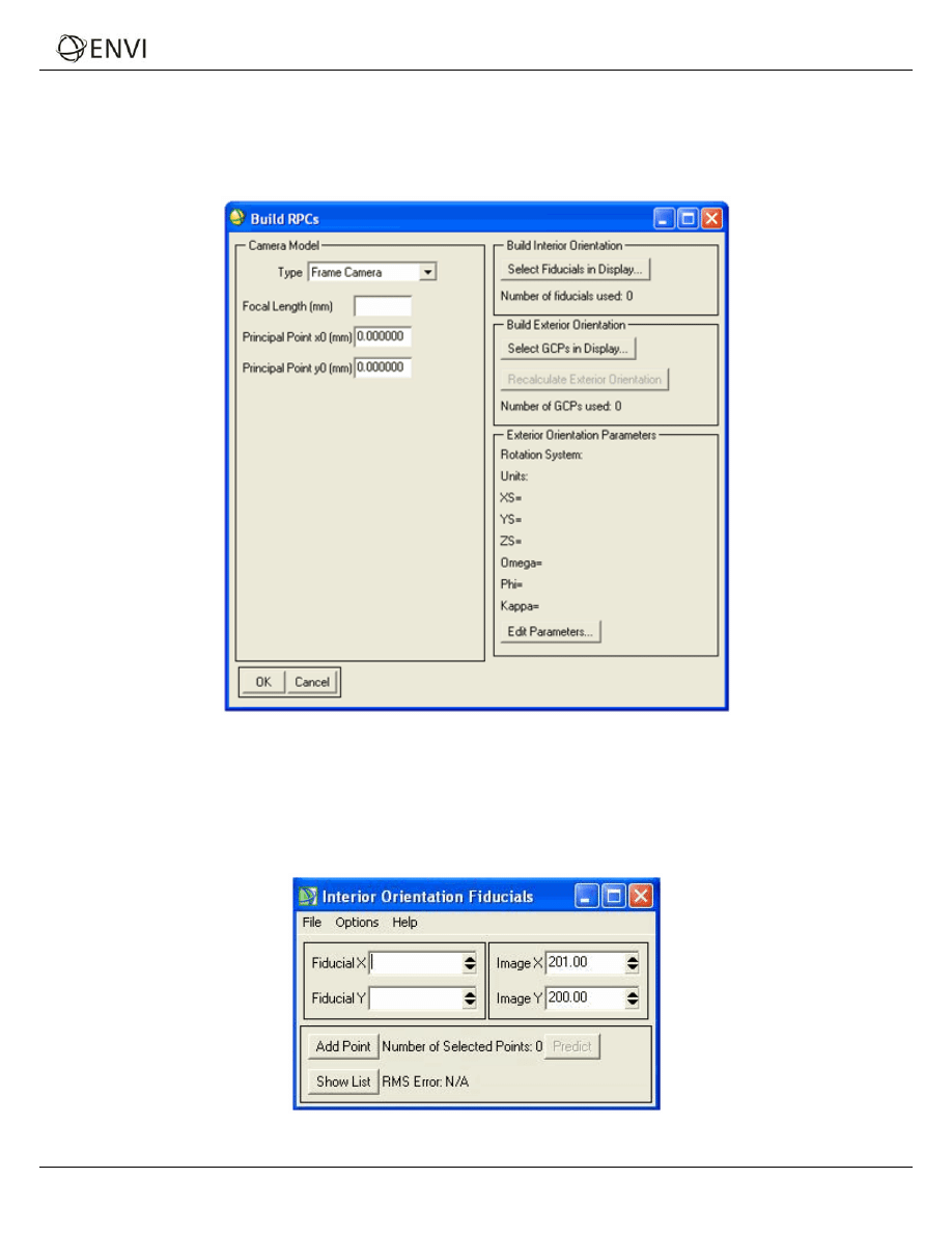
2. Select a scanned aerial photograph and click OK. The Build RPCs dialog appears.
3. From the Type drop-down list, select Frame Camera.
4. Enter a Focal Length (mm) value for the camera. This field is required.
5. Enter Principal Point x0 (mm) and Principal Point y0 (mm) coordinates, which are usually available from
the camera calibration report. The default value is 0 for both fields.
6. Click Select Fiducials in Display. ENVI automatically loads the scanned aerial photograph to a new display
group, and the Interior Orientation Fiducials dialog appears.
4
ENVI Tutorial: Orthorectifying Aerial Photographs
Tutorial: Orthorectifying Aerial Photgraphs
Build Interior Orientation
Interior orientation establishes the relationship between the camera model and the aerial photograph image. It uses tie
points between the aerial photograph and the camera fiducial marks (at least four) and the camera focal length.
The options in the Interior Orientation Fiducials dialog are similar to those in the Ground Control Points Selection dialog
for image-to-image registration. For more information, see "Image-to-Image Ground Control Points" in ENVI Help.
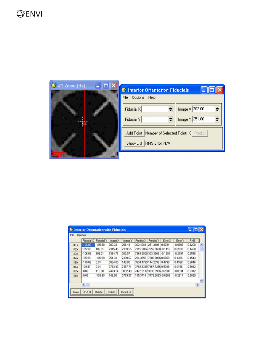
1. Select a fiducial mark location by centering the mouse cursor (crosshairs) in the Zoom window over it and
clicking. The image coordinates appear in the Image X and Image Y fields of the Interior Orientation Fiducials
dialog.
2. Enter the fiducial location in camera units (mm) in the Fiducial X and Fiducial Y fields. This information should
be available in the camera report.
3. Click Add Point to add the location to the list of tie points.
4. Continue selecting fiducial mark locations until you have at least four.
5. Click Show List at the bottom of the dialog to show the actual points and errors. Be sure to review the RMS
error in the Interior Orientation with Fiducials dialog to ensure that the points were properly selected. Following is
an example:
6. From the Interior Orientation Fiducials dialog menu bar, select Options → Export Fiducials to Build RPCs
Widget to compute interior orientation parameters. The Interior Orientation Fiducials dialog closes.
5
ENVI Tutorial: Orthorectifying Aerial Photographs
Tutorial: Orthorectifying Aerial Photgraphs
Build Exterior Orientation
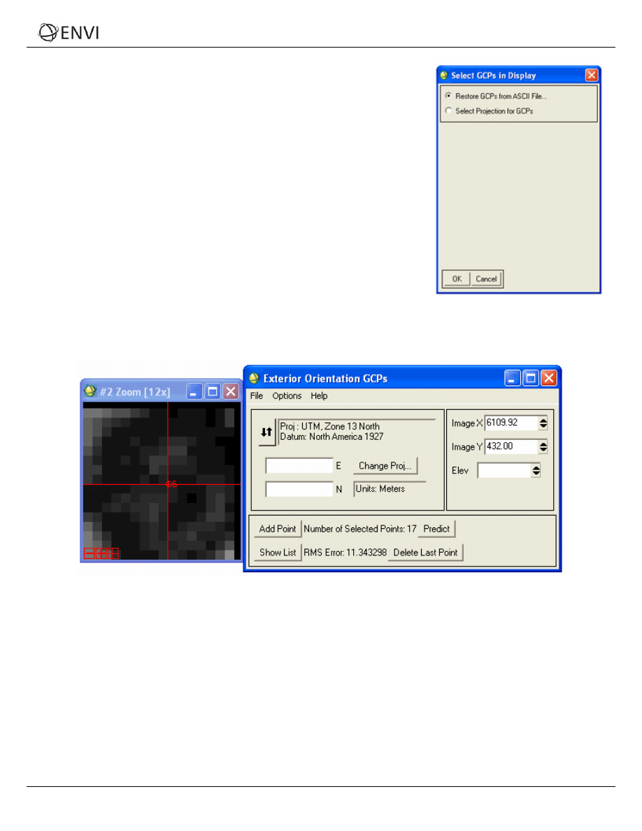
1. In the Build RPCs dialog, click Select GCPs in Display. The Select GCPs
in Display dialog appears.
2. Select one of the following options and click OK:
Restore GCPs from ASCII File — The Enter GCP Filename
dialog appears. Select a GCP file that contains projection
information (with a .pts extension). Click OK.
Select Projection for GCPs — The Select GCPs in Display dialog
appears. See "Selecting Map Projection Types" in ENVI Help for
more information on choosing a projection. You can also select
Restore GCPs from ASCII File from this dialog. Click OK.
3. The Exterior Orientation GCPs dialog appears. This dialog is similar to the
Ground Control Points Selection dialog for image-to-map registration. See
"Collecting Ground Control Points" in ENVI Help for more information.
4. Center the crosshairs in the Zoom window over a GCP and click once. The image coordinates appear in the Image
X and Image Y fields of the Exterior Orientation GCPs dialog.
5. Enter map coordinates for the GCP in the appropriate fields of the Exterior Orientation GCPs dialog.
6. In the Elev field, enter an elevation for the selected ground point.
7. Click Add Point to add the location to the list of GCPs.
8. Click Show List to display the Ground Control Points List dialog. This dialog is similar to the Image to Image GCP
List dialog. See "Using the Image to Image GCP List" in ENVI Help for more information.
9. Continue adding GCPs. You should spread the GCPs across the image, including all four corners, for best results.
Unlike the GCPs used in “warp” registrations, the accuracy of each GCP used for the exterior orientation is
absolutely critical for locating the position of the aerial camera. If the exterior orientation is not accurate, then the
orthorectified image will be in error, even if the interior orientation is perfect.
6
ENVI Tutorial: Orthorectifying Aerial Photographs
Tutorial: Orthorectifying Aerial Photgraphs
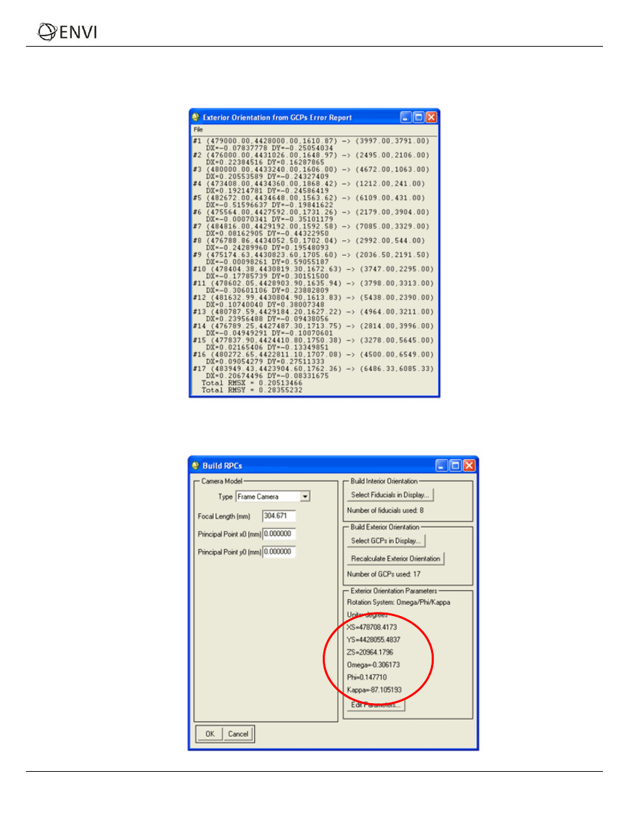
10. From the Exterior Orientation GCPs dialog menu bar, select Options → Export GCPs to Build RPCs Widget to
compute exterior orientation parameters. An Exterior Orientation from GCPs Error Report appears, which shows a
report of the individual RMS errors for each GCP, and the total RMS error.
The Build RPCs dialog lists six exterior orientation parameters (XS, YS, ZS, Omega, Phi, and Kappa), along with
the units of the rotation angles, and the rotation system used:
7
ENVI Tutorial: Orthorectifying Aerial Photographs

Tutorial: Orthorectifying Aerial Photgraphs
Compute RPCs
1. Click OK in the Build RPCs dialog. The Scene Elevation in Meters dialog appears.
2. The Minimum Elevation and Maximum Elevation fields are initially populated with the range of global
elevation values from the file world_dem (found in the data directory of your ENVI installation path). If you
know the elevation range of your scene, you can enter new Minimum Elevation and Maximum Elevation
values. These values represent the height above the WGS-84 ellipsoid for the geographic region that the image
covers.
3. Click OK. After processing is complete, an ENVI Message dialog appears: “RPCs have been calculated for this file,
and the header has been updated.” Click OK.
After ENVI computes the RPCs, it adds the RPC information to the input file header so that you can use the file with
ENVI’s Generic RPC orthorectification tool.
8
ENVI Tutorial: Orthorectifying Aerial Photographs
Tutorial: Orthorectifying Aerial Photgraphs
Orthorectify the Aerial Photograph
1. From the ENVI main menu bar, select Map → Orthorectification → Generic RPC and RSM → Orthorectify
using RPC or RSM. The Select File to Orthorectify dialog appears.
2. Select your original, scanned aerial photograph and click OK. ENVI recognizes the RPC information in the file
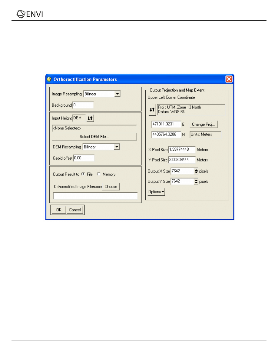
header, and the Orthorectification Parameters dialog appears.
Select a DEM
You can use a digital elevation model (DEM) to determine the elevation of each pixel in the scanned aerial photograph.
However, you should consider the issue of spatial resolution, as it has a profound effect on your results. There are three
key parameters:
The pixel size of the DEM.
The pixel size of the input image.
The desired output pixel size for the resulting orthorectified image.
ENVI lets you proceed with any combination of pixel sizes. Ideally, the pixel size of the DEM should be the same (or
smaller) as that of the output ortho image you want to create.
If the DEM resolution is significantly larger than the desired output resolution, you may end up with artifacts in the ortho
result that look like steps (or blocks) in the image. The steps occur where there is a boundary between groups of pixels in
the output ortho image which map back to the same DEM elevation (i.e., the same DEM pixel).
1. In the Orthorectification Parameters dialog, ensure the Input Height toggle button is set to DEM.
2. Click Select DEM File. The Select Input DEM Band dialog appears.
9
ENVI Tutorial: Orthorectifying Aerial Photographs

Tutorial: Orthorectifying Aerial Photgraphs
3. Select a DEM file and click OK.
4. In the Orthorectification Parameters dialog, select an option from the DEM Resampling drop-down list. The
resampling technique converts the DEM from the source image coordinate system to Geographic (WGS-84),
which is required for input into the RPC algorithm. ENVI performs a full projection to convert each DEM
coordinate into the correct coordinate system.
5. Enter a Geoid offset value. This is a constant value that is added to every value in the DEM to account for the
difference between a spheroid mean sea level (used in most available DEM data) and the constant geopotential
surface known as the
geoid. This information must be used to provide accurate orthorectification.
For example, if the geoid is 10 m below mean sea level at the location of your image, enter a value of -10.
Many institutions doing photogrammetric processing have their own software for geoid height determination. You
can also obtain software from NGA, USGS, NOAA, and other sources. A geoid height calculator is located at:
http://www.ngs.noaa.gov/cgi-bin/GEOID_STUFF/geoid99_prompt1.prl
.
6. Select output to File or Memory.
7. To change the map projection, click Change Proj.
8. The output pixel size for the orthorectified image defaults to the pixel size of the input image. To change the pixel
size or number of samples or lines, enter the information in the X Pixel Size, Y Pixel Size, Output X Size, and
Output Y Size fields.
It is always a good idea to check these values before performing orthorectification, because a quick glance at
these parameters can often identify problems with input parameters.
9. Click Options and select from the menu to manage the output projection and map extent settings.
10. Click OK. ENVI orthorectifies the aerial photograph and adds the resulting output to the Available Bands List.
Notes about Resampling
When producing the orthorectified image, the value for each pixel in the output image is determined by figuring out
which pixel in the input aerial photograph “belongs” in this position. This is accomplished by tracing back which aerial
photograph digital number (DN) occurs at a given map coordinate. This DN is then placed in the correct location in the
orthorectified image.
While the map coordinate of the center of each pixel in the output image maps back to a single pixel in the input image,
the value ENVI uses for the output image is typically adjusted by resampling it based on the values of the pixels in its
immediate vicinity (in the aerial photograph). This resampling produces a smoother, more realistic looking, orthorectified
image.
Bilinear interpolation uses the values of the 4 nearest neighbors, while cubic convolution uses the 16 nearest neighbors.
Generally speaking, cubic convolution resampling offers the best smoothing results, but it is the most time-consuming.
Nearest-neighbor resampling is the fastest method, but it results in the coarsest smoothing effects. Bilinear resampling
tends to be a good trade-off between computational time and smoothing effects.
10
ENVI Tutorial: Orthorectifying Aerial Photographs
Document Outline
Wyszukiwarka
Podobne podstrony:
10 Orthorect Aerial
11 Orthorect RPC
40 RPC Orthorectification
Polska z lotu ptaka Aerial footage of Poland
Victor Appleton Tom Swift and His Aerial Warship
US Patent 1,655,113 Method Of Aerial Transportation
Orthorect RPC
Maverick in the Sky The Aerial Adventures of World War I Flying Ace Freddie McCall
Orthorexia 2
Aerial Photography
US Patent 1,655,114 Apparatus For Aerial Transportation
Gods Eye Aerial Photography and the Katyn
więcej podobnych podstron