
L-Jetronic Fuel Injection Systems
for BMW E12’s
Peter Florance

Introduction
n
This seminar will describe the L-Jetronic system
fitted on E12’s
n
It will also cover trouble shooting and
performance tips

Seminar Topics
n
Basic Engine Combustion Process
n
Combustion Requirements
n
Fuel Delivery Implementations
n
Electronic Fuel Injection System Components
n
L-Jetronic System
n
Troubleshooting
n
Conversion to Lambda Control
n
Performance

Basic Engine Combustion
Process
n
Fuel and Air intake
n
Compression
n
Combustion
n
Exhaust
n
And so on and so on…..

Combustion Requirements
n
Compression
n
Air
n
Fuel
n
Spark
n
Air and fuel need to be in 14.7 to 1 ratio for
efficient combustion
n
Understanding these requirements will help
explain the L-Jetronic components and their role
in the injection system

Implementations
n
Carburetors
n
Fuel Injection
u
Mechanical
F
Kugelfisher - 2002tii
F
K-Jetronic - 320i
u
Electronic
F
L-Jetronic (Electronic - fuel injection only) 530i 528i
F
Motronic (Computerized with ignition) 535i 528e
n
Most modern fuel injection systems are
computerized

Electronic Fuel Injection System
Components
n
Throttle and idle/WOT switches
n
Air Mass Measurement
n
Fuel Pump
n
Fuel Injectors
n
Pressure regulation
n
Control Unit (some with O2 control)
n
Combo Relay
n
Cold Start
n
Warm up enrichment
n
Warm up Idle compensation

L-Jetronic System - Throttle and idle
control
n
Throttle opens to allow more air to sucked in to engine
n
Small amount of air bypasses the throttle so the engine
gets air and will idle. Screw on side of throttle adjusts idle
speed.
n
Auxiliary air valve bypasses more air during warm-up to
compensate for thicker oil.
n
Air conditioned cars have another bypass valve that
operate when compressor is running to compensate for
load of AC.
n
Aux Air Valve DOES NOT control mixture.
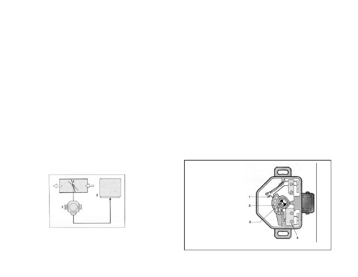
L-Jetronic System - Throttle and
idle/WOT switches
n
Switches on throttle tell ECU what special position
the throttle is in
u
Idle, off-idle, wide open throttle (WOT).
u
ECU has special mixtures for these two conditions
1 Full load contact
2 Contact path
3 Throttle valve shaft
4 Idle contact
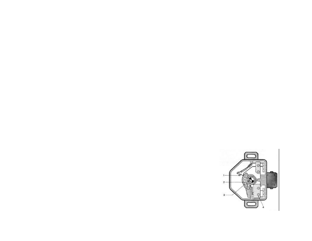
L-Jetronic System – Throttle and
Idle/WOT switches
•Idle switch is used for coasting fuel-cutoff on later models(E12 79-81). When
switch is closed (throttle closed), fuel is cut until engine rpm drops below ECU
specified value.
•If idle is set too high, the coasting fuel-cutoff with cause the idle to cycle up
and down as the ECU cuts fuel until idle drops below spec, then fuel resumes,
RPM rise above spec and fuel is cut again. To test, unplug throttle switch or idle
switch on units with separate switches. If idle is above spec (1400 for US 528i
set it too spec and re-connect the switch
1 Full load contact
2 Contact path
3 Throttle valve
shaft
4 Idle contact
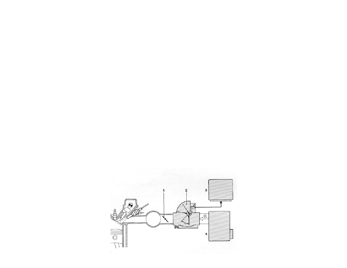
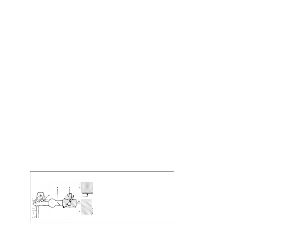
L-Jetronic System - Air Mass
Measurement
n
Fuel Injection System has to know mass of air
n
Airflow meter provides air mass flow information
u
Mass is calculated by volume (flow) and density
F
Need device to determine flow air
•
Flap on airflow meter
F
Need temperature to determine density
•
Temperature sensor in air flow meter (AFM)
1 Throttle plate
2 Air Flow Meter (with
temperature sensor)
3 ECU
4 Air cleaner box
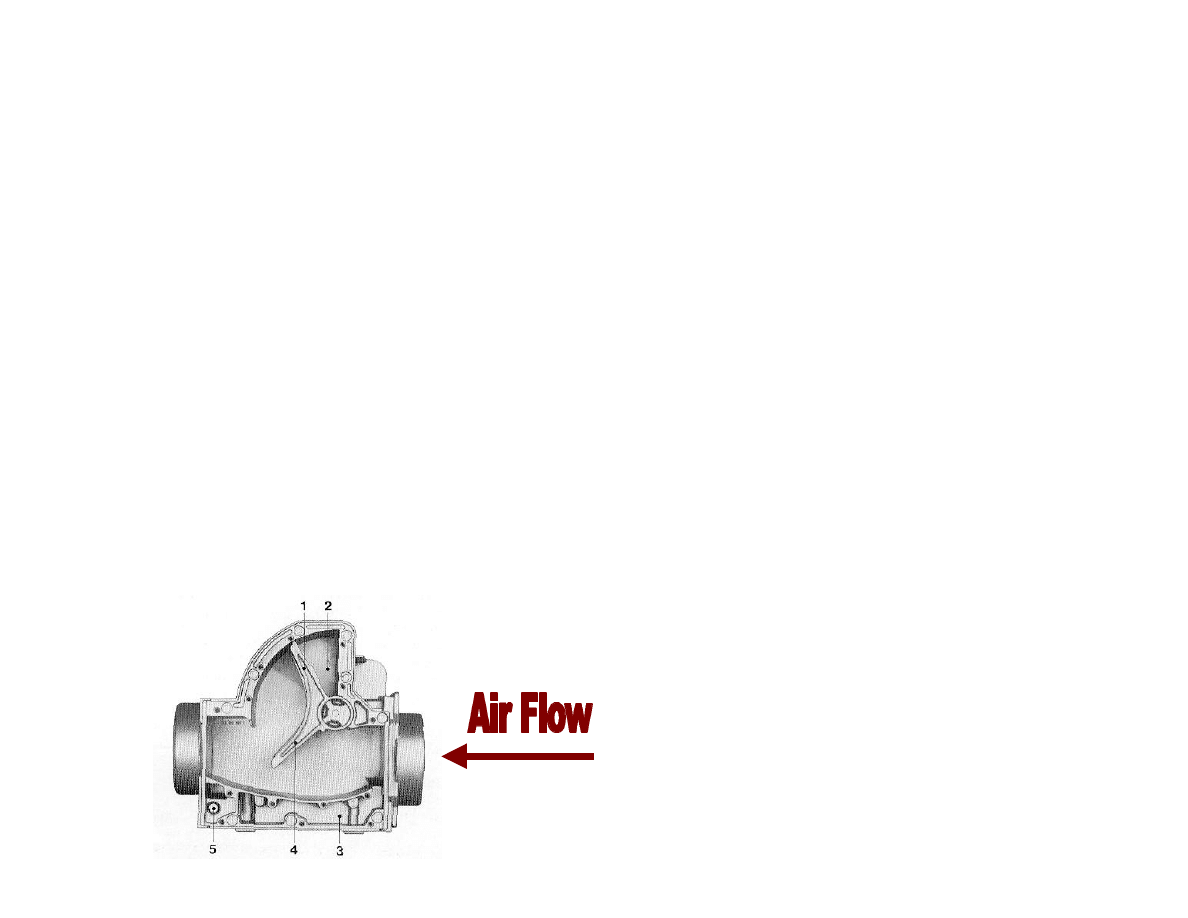
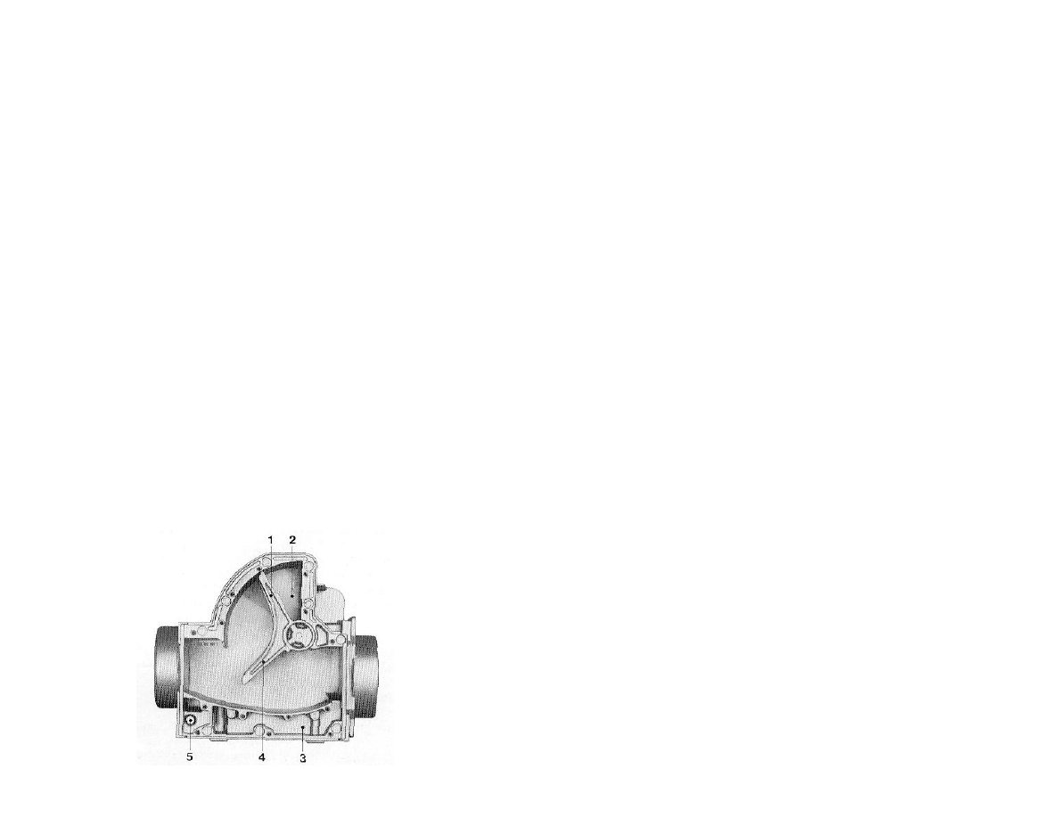
L-Jetronic System - Air Flow
Meter - Mechanical Components
n
AFM measures flow by spring loaded flap (door)
n
Greater flow forces flap open.
n
Compensation flap and damping chamber act like
shock absorber allowing door to settle quickly and
to make it insensitive to vacuum pulsation’s from
cylinders
1 Compensation Valve
2 Damping Chamber
3 Air Bypass (idle mixture)
4 Air Sensor Flap
5 Idle mixture adjusting screw
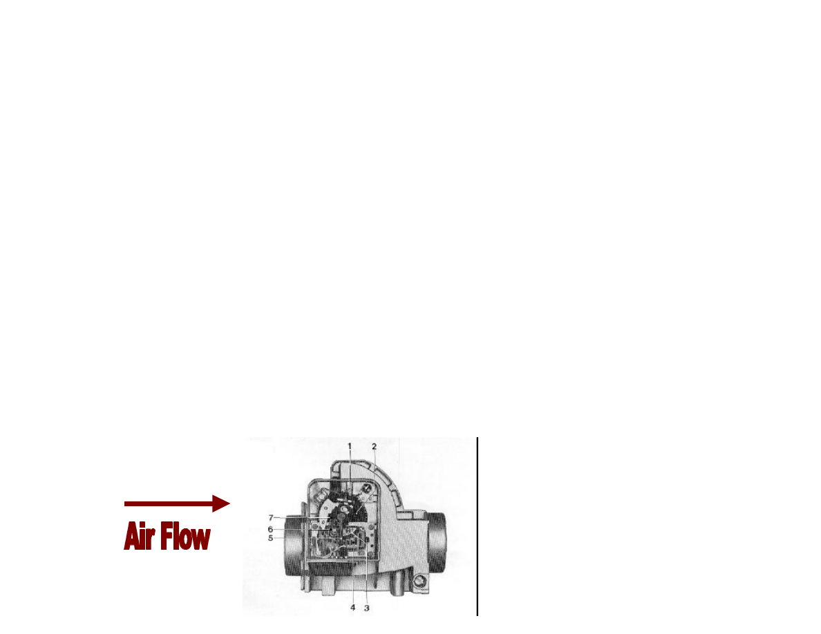
L-Jetronic System - Air Flow
Meter - Electrical Components
u
Spring loaded flap causes wiper to move along
resistance track.
u
Resistance track has constant voltage applied to it.
u
As wiper moves with flap, wiper voltage varies with
amount of opening
F
full open - max voltage, full closed - min voltage
F
Voltage is proportional to fuel. More voltage, more
fuel.
1 Gear for door spring load
2 Return Spring
3 Wiper Track
4 Resistance Element on ceramic substrate
5 Wiper tab
6 Wiper
7 Fuel Pump Switch
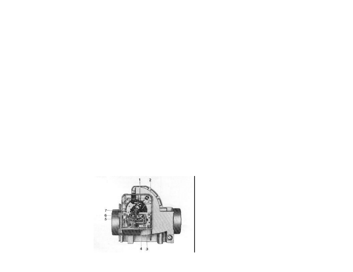
L-Jetronic System - Air Flow Meter -
Electrical Components
n
Spring can be adjusted. Looser, door opens easier, causing mixture to
be richer. Tighter door, requires more force (more air) , therefore
leaner.
n
Fuel pump switch activates when door opens. When engine quits, fuel
pump will not run for safety (accident).
1 Gear for door spring load
2 Return Spring
3 Wiper Track
4 Resistance Element on ceramic substrate
5 Wiper tab
6 Wiper
7 Fuel Pump Switch
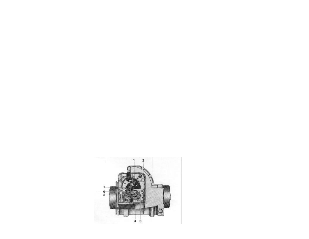
L-Jetronic System - Air Flow
Meter - Electrical Components
n
Voltage is sent to ECU
n
AFM contains temperature sensor (not shown).
Temp info is sent directly to ECU for mass
calculation.
1 Gear for door spring load
2 Return Spring
3 Wiper Track
4 Resistance Element on ceramic substrate
5 Wiper tab
6 Wiper
7 Fuel Pump Switch

L-Jetronic System - Air Flow
Meter - Fuel Calculations
n
The ECU uses mass measurement to meter fuel
through injectors.
n
When accelerating, the door will overshoot
slightly.
u
This overshoot causes extra fuel to be delivered
through injectors
u
This serves as accelerator pump similar to
carburetors
L-Jetronic System - Air Flow
Meter - Idle Mixture
n
Idle mixture is adjusted by adding additional air to
fixed idle mixture. Idle screw (underneath AFM
adjusts amount of bypassed air (not measured by
AFM). This way mixture can be adjusted.
u
Note effect of idle screw is not significant at higher
airflow, only idle
1 Compensation Valve
2 Damping Chamber
3 Air Bypass (idle mixture)
4 Air Sensor Flap
5 Idle mixture adjusting screw
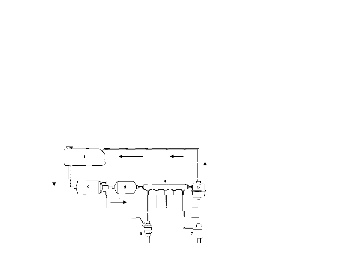
L-Jetronic System - Fuel Flow
n
Fuel is pumped up to fuel rail and excess returned to tank
n
Because so much fuel is circulated, filter is quite large.
n
Fuel lines are at high pressure (> 35psi), use BMW factory
hose for replacement
n
Inspect lines regularly, fuel under pressure can cause
LARGE fire.
1 Fuel Tank
2 Fuel Pump w/ Check Valve
3 Fuel Filter
4 Fuel Rail
5 Pressure regulator
6 Fuel Injector
7 Cold Star Valve
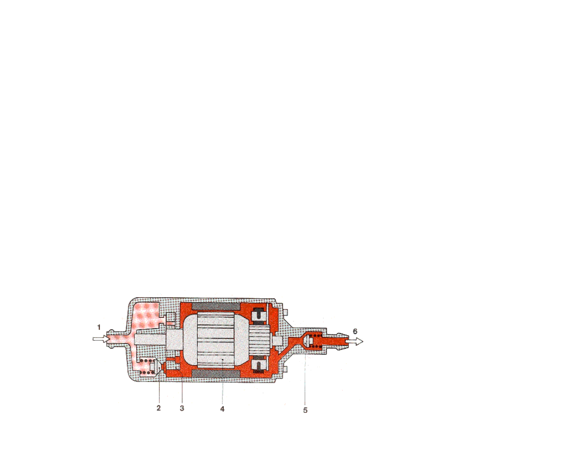
L-Jetronic System - Fuel Pump
n
Uses positive displacement roller pump.
n
Electric motor is in fuel stream and uses fuel to cool it.
u
Because there is no air, it won’t explode.
n
It’s important not to run low on fuel as the pump can
overheat and fail if fuel starved.
n
Check fuel pump fuse (fuse #1, 16 amp) for corrosion -
common no start or stall failure. I replace every 2 years
and clean the fuse holder contacts.
1 Suction Side (inlet from tank)
2 Pressure relief valve
3 Roller pump mechanism
4 Motor
5 Check valve
6 Pump discharge (outlet to
filter)
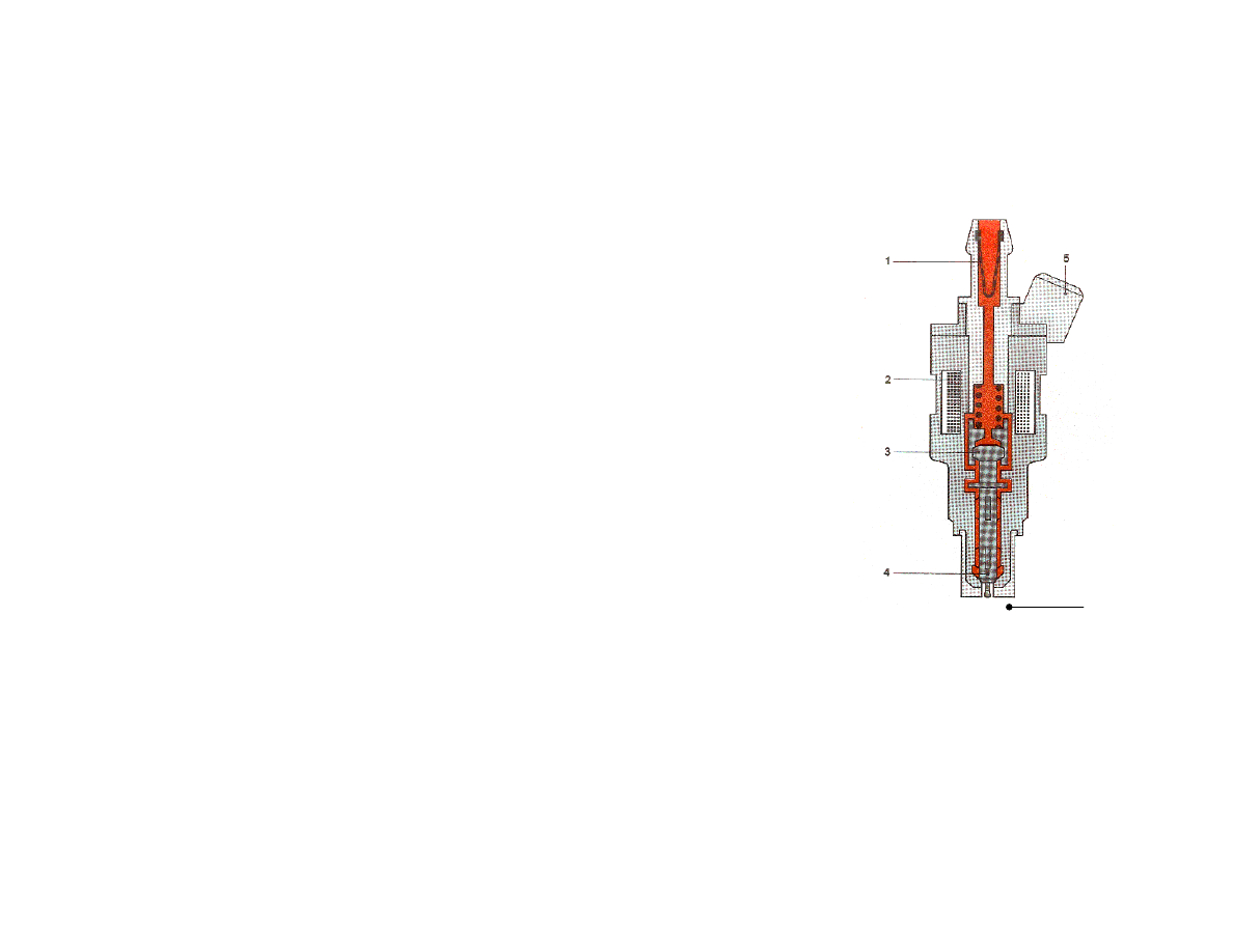
L-Jetronic System - Fuel Injectors
n
Open when energized by ECU- not
continuous as K-Jetronic.
n
Current through windings causes magnetism
pulling armature and attached needle valve
up and way from valve seat allowing fuel to
flow. Can test with magnet on a stick.
n
All injectors are wired together and fire
simultaneously,
n
Flow is determined by pressure across
injector and time (dwell) of opening.
n
Normally more reliable than K-Jetronic type.
See Rowe
4
.
1 Screen mesh filter
2 Solenoid Winding
3 Solenoid Armature
4 Needle Valve
5 Electrical Connection
6 Valve Seat
6
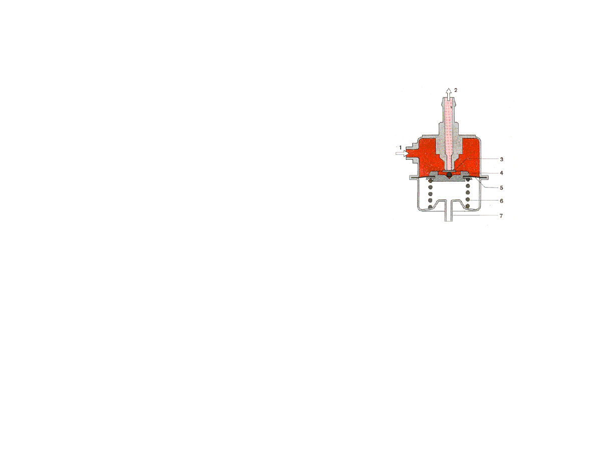
L-Jetronic System - Pressure Regulator
n
Provides constant pressure across
fuel injector valve
n
Fuel
1
under pressure from fuel
pump enters and pushes against
valve holder
4
and spring
6
which
opens valve
3
at regulated
pressure; allowing excess fuel
2
to
escape back to tank
u
All the fuel between the pump and this
valve are at the regulated fuel
pressure.
n
Vacuum diaphragm
5
works
against spring to create less
pressure when intake
7
is under
vacuum so net pressure is
constant
1. Fuel inlet (from fuel injectors and
pump)
2. Fuel Outlet (to return line back to
fuel tank
3. Valve Plate (blocks return line)
4. Valve Holder
5. Vacuum Diaphragm (compensates
for intake manifold vacuum)
6. Compression Spring (sets
regulation pressure)
7. Vacuum connection (from intake
manifold)

L-Jetronic System - Control Unit
n
Control unit (ECU) takes sensor information:
u
AFM flow and temperature
u
Engine RPM (from ignition)
u
Warm up information (from coolant temperature sensor)
u
Throttle mode (idle and WOT switches)
u
O2 sensor in Lambda systems
n
….and calculates opening duration of injectors
n
This ‘map’ is hardwired into system (there’s no chip
available to modify)
n
Some users have adjusted value of internal
components
5
.

L-Jetronic System - Control Unit -
Throttle Operating Modes
n
Idle
u
Throttle is closed
u
Idle switch is closed, ECU supplies idle mixture (a little rich) for
smooth idle
n
Off - idle
u
Both switches are open. ECU reads AFM signal and O2 sensor
(where installed) and determines how long to open injectors for
proper mixture.
n
Wide Open Throttle (WOT)or ‘Yeeeehaaaa! zone’
u
WOT switch is closed
u
Injector open time is fixed amount. Somewhat rich for added
power.
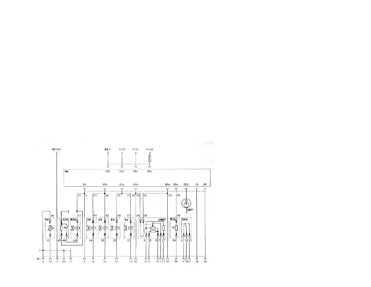
L-Jetronic System - Control Unit, Basic
Schematic
n
This is a generic system schematic.
n
Haynes diagram is good, but owners manual shows more
internal component detail
TF Coolant Temp Sensor
TZS Thermo-time switch
KSV Cold Start Valve
EV Fuel Injector
LMM Air Flow Meter (AFM) with pump
switch and air temperature sensor
ZLS Auxiliary Air Valve
DKS Throttle Switch (idle, WOT)
EKP Electric Fuel Pump
RK Fuel Injection Combo Relay
ZS Ignition Coil
BA Battery
ST Multi-pin connector to ECU

L-Jetronic System - Control Unit Pin out
Seen into the female connectors.
+----------------------------------------------------+
| o o o o o o o o o o o o o o o o o |
+-----+ 35 34 33 32 31 30 29 28 27 26 25 24 23 22 21 20 19 +----+
| o o o o o o o o o o o o o o o o o o |
| 18 17 16 15 14 13 12 11 10 9 8 7 6 5 4 3 2 1 |
+---------------------------------------------------------------+
1. Ignition coil 19. No connection
2. Throttle switch, idle ? 20. Main relay + engine running
3. Throttle switch, WOT ? 21. No connection
4. Pin 50 via main relay 22. No connection
5. Earth connection 23. No connection
6. Air flow sensor + ? 24. No connection
7. Air flow sensor signal 25. No connection
8. Air flow sensor - ? 26: No connection
9. Air flow sensor air temp. 27. Air flow sensor
10. Main relay, pin 15 28. No connection
11. No connection 29. No connection
12. No connection 30. Injectors
13. Coolant temperature sensor 31. Injectors
14. Injectors 32. Injectors
15. Injectors 33. Injectors
16. Earth connection 34. Auxiliary air valve, bimetal
17. Earth connection 35. Earth connection
18. Throttle switch +

L-Jetronic System - Lambda - Why?
n
Basic L-Jetronic System measures air mass and
provides appropriate amount of fuel
n
Note: although a precision system, there is no
feedback for the system to know of any variances:
u
Aging components
u
Fuel characteristic differences
n
Catalytic converters require precise mixture
control for operation
n
The air fuel ratio of standard L-Jetronic system is
not accurate enough for proper catalytic converter
operation
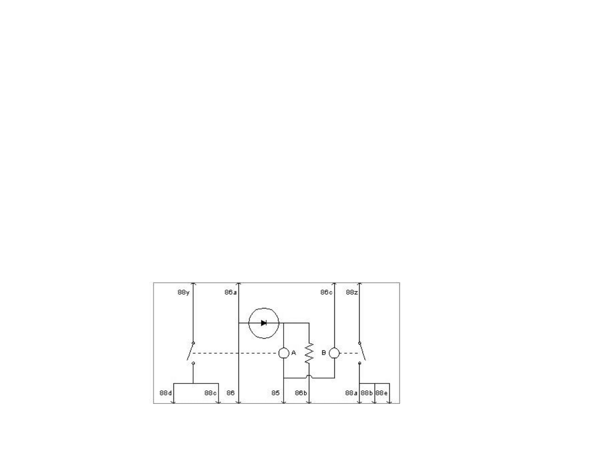
Combo Relay – Power and interface for
the L jet system.
•Combo relay provides switched power to ECU and injectors
•Combo relay provides power to fuel pump (only when either air flow meter is
open or engine is cranking)
•Combo relays are built on PC boards which can get bad solder joints

L-Jetronic System - Lambda -
Components O2 Sensor
n
O2 Sensor measures excess oxygen in exhaust
gas. Sensors must be hot to work. Some have
heating elements to start operating faster.
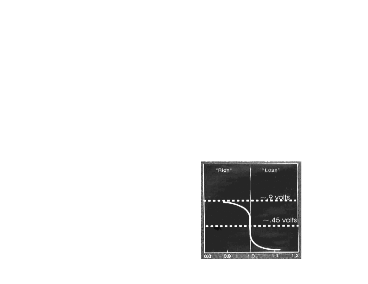
L-Jetronic System - Lambda -
Components O2 Sensor Output Curve
n
The sensors output changes rapidly around the 14.7 to 1 ratio. This
provides a mixture with just enough oxygen to burn hydrocarbons in
catalytic converter.
n
The lambda system controls around this point. The ECU cycles
mixture lean and rich slightly. It looks at the average of the lambda
signal and adjusts the average of the mixture accordingly.
Excess Air Factor (Lambda)
Sensor Voltage
L-Jetronic System - Cold Start
n
Extra fuel is required during cold start
n
Cold start valve is operated for up to 30 seconds
by thermo-time switch.
u
Switch is temperature and time sensitive.
Cold Start Valve
Thermo time switch
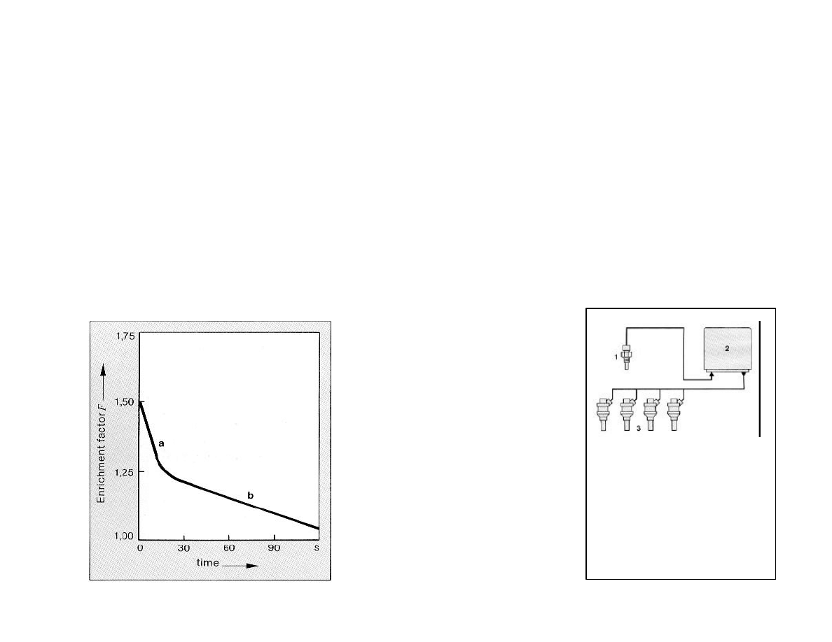
L-Jetronic System - Warm up enrichment
n
Once started ECU looks at coolant temperature to decide how much
extra fuel to supply.
n
Once at operating temperature, the warm up enrichment ceases.
Warm up enrichment
factor curve.
Curve a is cold start and warm
up enrichment (extra fuel)
combined. Note cold start valve
and injectors are supplying fuel
Curve b is warm up enrichment
only (thermo time switch opens
and cold start valve ceases
operation.
At right hand side, warm up is
nearing completion and
enrichment tapers off.
Enrichment fuel supply
1 Cold Start Valve
2 Injectors
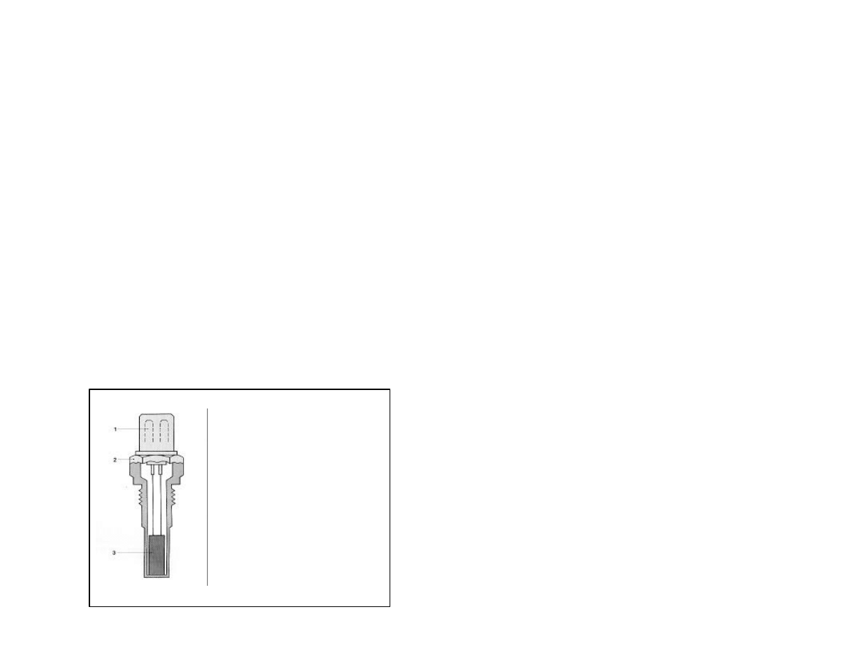
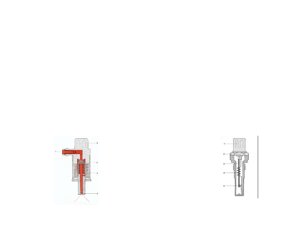
L-Jetronic System - Warm up enrichment
Components - Coolant Temp Sensor
n
Coolant temperature sensor mounted in
thermostat housing.
n
Sensor has high resistance when cold and low
when warm.
n
Connections do get intermittent - check for
corrosion
1 Electrical
connection
2 Housing
3 NTC Resistor
L-Jetronic System - Warm up Idle
compensation
n
During Warm-up, engine oil is thicker adding load to
engine
n
Auxiliary air valve bypasses throttle for additional air (like
mini - throttle) while warming up. This brings idle speed up
to desirable level
n
Electrical heating element inside valve combined with
engine heat bend bi-metal strip causing valve to close.
This happens gradually reducing amount of throttle ‘help’.
Once warm, valve is closed
1 Blocking Plate
2 Bi-metal strip
3 Electric heating
element
4 Electrical connection

Troubleshooting
Ask us questions!!

Conversion to Lambda Control
By Scott Stewart - First Fives Registry
Greg’s note:
If you have a 528i, you don't have to worry about this, but if you have a 530i, keep reading.
The following describes the process of converting your fuel injection system to the later
style Bosch L-Jetronic with lambda control.
The object here is to assemble a FI system that is properly tuned, provides good
driveability, low fuel consumption, and has minimal emissions.
I had my 530i checked for emissions after I retrofitted my L-jet with Lambda control FI
system from a 528i. It's emissions are lower without a catalytic converter than what the
original specs call for on a 1977 530i. The L-jet with lambda control FI system is leap
years ahead of the one on your car now because it actually monitors the fuel/air
(stoichometric) ratio rather than assuming it is OK. My performance is up, driveability is
much better (my car would flood at high rpm’s when it was cold before I changed to the
new system) better fuel consumption, and of course the lower emissions.
Following is a quick list of the components I assembled for the conversion. Any questions,
additions, or comments are welcome from those that currently drive "the real thing" 528i
or from others who have done this conversion (Marty Roach).

Conversion to Lambda Control - Continued; Parts List
All parts were removed from a running 1981 528i:
l
122 extension ECU, same connection as the 106 original model in the 530i. Make sure
you plug in the single spade terminal at the ECU that is not part of the FI wiring harness.
I think this plug is the distributor pickup or Pin #1 on the ECU (help here from those in
the know).
l
Complete FI and engine wiring harness from the 528i
l
528i valve cover
l
528i throttle body with 4 contact limit switches
l
528i AFM
l
auxiliary air valve and AC bypass valve off of 528i
l
exhaust manifold down-pipe with threaded port for 02 sensor
l
528i combo relay
l
later style vacuum advance/retard distributor with transistorized ignition, ignition module,
resistor bank etc. Mount it on inside of uni-body behind the windshield washer bottle
with heatsink grease (resistor bank gets pretty hot). Don't forget the engine wiring
harness coming from the ignition module to the distributor, ignition coil, temperature
sending unit, alternator (power and spade terminal for idiot light), and oil pressure
sending unit. This harness will have a plug that plugs right into your fuse box.
l
528i thermostat housing with fittings for vacuum retard during cold running, temp time
switch, temp sending unit for gauge and FI (this makes the FI wiring harness much
easier to fit)
l
528i plenum chamber
l
528i fuel rail, fuel pressure regulator, injectors.

Conversion to Lambda Control - Continued; summary
I am sure you are saying WHAT!! by now but believe me it is worth the hassle. I don't know if
the exhaust manifold from a 528i is necessary, my car had headers on it so I never saw
the original 530i exhaust manifold.
OK. Thanks to Peter Florance I just happen to know the only mods that are necessary to the
wiring in your car once the FI and engine wiring harness are in place are:
Remove the purple/green and yellow/green wires from the Fuel pump side plug in your
combo relay (easily done with a knife that will flatten the tab that holds the terminal in the
plug). Remove these same two wires from the Fuel pump side plug of the combo relay
that came on the new 528i wiring harness and replace these wires with the two out of
your harness. Tie wrap everything down and tape up the old combo relay plug with
electrical tape (the main power, red, wire still has power to it)and start the car.
I hope some of this helps you or anyone else brave enough to perform the upgrade.
Scott Stewart
Peter’s note: We are trying to see if this can be done w/out the harness swap.

Bibliography and Suggested
Reading
1
Technical Instruction L-Jetronic - # VDT-U 33 En - Robert Bosch
GmbH
2
Owners Workshop Manual BMW 528i & 530i - Haynes Publishing
Group ISBN 0 85696 632 0
3
Bosch Fuel Injection and Engine Management - Charles O.
Probst, SAE - Robert Bently Publishers #GFIB; ISBN 0-8376-
0300-5
4
BMW Fuel Injection - Jim Blanton & Jim Rowe - Metric Mechanic
Kansas City, MO 816-842-7232
5
First Fives Web Site Technical FAQ - htpp://www.firstfives.org
Wyszukiwarka
Podobne podstrony:
Gasoline Fuel Injection System K Jetronic
Fuel Injection Systems Bosch Cis
Mechanics of a Diesel Fuel Injection System
SMeyer CA2067735A1 Water Fuel Injection System
Self Study Programme 351 Common rail fuel injection system fitted in the 3 0l V6 TDI engine
Bosch K Jetronic And Ke Jetronic Mechanical Fuel Injection Haynes
BOSCH HDI EDC15C2 injection system (2)
Fuel injection ASZ
Pytania i odpowiedzi ? 9 Fuel Oil System
BMW 735 series 1990
BMW 325 series 1992
New valve series for large refrigeration systems
BMW 318 series 1991
BMW 325 series 1990
BOSCH HDI EDC15C2 injection system (2)
ACCELERATOR CONTROL, FUEL & EXHAUST SYSTEMS
Hydrogen Gas Injector System For Internal Combustion Engine
więcej podobnych podstron