Chapter 4 Part B:
Bosch K-Jetronic and KE-Jetronic
mechanical fuel injection systems
Accelerator pedal - removal and refitting . . . . . . . . . . . . . . . . . . . . . .5
Air cleaner - removal and refitting . . . . . . . . . . . . . . . . . . . . . . . . . . .2
Air cleaner element renewal . . . . . . . . . . . . . . . . . . . . .See Chapter 1
Auxiliary air device - removal and refitting . . . . . . . . . . . . . . . . . . . .10
Charge air temperature sensor - removal and refitting . . . . . . . . . .17
Cold start valve - removal and refitting . . . . . . . . . . . . . . . . . . . . . . .9
Electro-magnetic pressure actuator - removal and refitting . . . . . .15
Fuel accumulator - removal and refitting . . . . . . . . . . . . . . . . . . . . . .7
Fuel distributor - removal and refitting . . . . . . . . . . . . . . . . . . . . . . .11
Fuel filter renewal . . . . . . . . . . . . . . . . . . . . . . . . . . . . .See Chapter 1
Fuel injection control module - removal and refitting . . . . . . . . . . . .16
Fuel injectors and delivery pipes - removal and refitting . . . . . . . . . .8
Fuel pressure regulator - removal and refitting . . . . . . . . . . . . . . . .13
Fuel pump - removal and refitting . . . . . . . . . . . . . . . . . . . . . . . . . . .6
Fuel tank - removal and refitting . . . . . . . . . . . . . . . . . . . . . . . . . . . . .3
General information and precautions . . . . . . . . . . . . . . . . . . . . . . . . .1
Idle speed and mixture adjustment . . . . . . . . . . . . . . . .See Chapter 1
Idle speed compensator - removal and refitting . . . . . . . . . . . . . . .19
Intercooler - removal and refitting . . . . . . . . . . . . . . . . . . . . . . . . . .22
Thermo-time switch - removal and refitting . . . . . . . . . . . . . . . . . . .18
Throttle cable - adjustment, removal and refitting . . . . . . . . . . . . . . .4
Throttle housing - removal and refitting . . . . . . . . . . . . . . . . . . . . . .12
Turbocharger - general description . . . . . . . . . . . . . . . . . . . . . . . . .20
Turbocharger - removal and refitting . . . . . . . . . . . . . . . . . . . . . . . .23
Warm-up regulator - removal and refitting . . . . . . . . . . . . . . . . . . . .14
Waste gate solenoid control valve - removal and refitting . . . . . . . .21
General
System type . . . . . . . . . . . . . . . . . . . . . . . . . . . . . . . . . . . . . . . . . . . . . .
Bosch mechanical continuous injection system
Application:
XR3i and XR3i Cabriolet models up to 1990 . . . . . . . . . . . . . . . . . . .
Bosch K-Jetronic
RS Turbo models . . . . . . . . . . . . . . . . . . . . . . . . . . . . . . . . . . . . . . . .
Bosch KE-Jetronic
K-Jetronic system specification
Fuel pump type . . . . . . . . . . . . . . . . . . . . . . . . . . . . . . . . . . . . . . . . . . . .
12 volt electric roller cell type
Fuel pump delivery quantity (minimum) . . . . . . . . . . . . . . . . . . . . . . . . .
0.7 litre (1.32 pints) in 30 seconds
Idle speed (cooling fan on) . . . . . . . . . . . . . . . . . . . . . . . . . . . . . . . . . . .
750 to 850 rpm
Idle mixture CO content . . . . . . . . . . . . . . . . . . . . . . . . . . . . . . . . . . . . .
1.0 to 1.5%
Main system pressure . . . . . . . . . . . . . . . . . . . . . . . . . . . . . . . . . . . . . . .
4.7 to 5.5 bar (68 to 80 lbf/in
2
)
Control pressure (warm engine) . . . . . . . . . . . . . . . . . . . . . . . . . . . . . . .
3.4 to 3.8 bar (39 to 45 lbf/in
2
)
Injector valve opening pressure . . . . . . . . . . . . . . . . . . . . . . . . . . . . . . .
3.2 to 4.0 bar (46.4 to 51.5 lbf/in
2
)
KE-Jetronic system specification
Fuel pump type . . . . . . . . . . . . . . . . . . . . . . . . . . . . . . . . . . . . . . . . . . . .
12 volt electric roller cell type
Fuel pump delivery quantity (minimum):
1985 models . . . . . . . . . . . . . . . . . . . . . . . . . . . . . . . . . . . . . . . . . . . .
1.1 litres (1.9 pints) in 60 seconds
1986 models onwards . . . . . . . . . . . . . . . . . . . . . . . . . . . . . . . . . . . . .
2.5 litres (4.4 pints) in 60 seconds
Idle speed (cooling fan on):
1985 models . . . . . . . . . . . . . . . . . . . . . . . . . . . . . . . . . . . . . . . . . . . .
800 to 900 rpm
1986 models onwards . . . . . . . . . . . . . . . . . . . . . . . . . . . . . . . . . . . . .
920 to 960 rpm
Idle mixture CO content:
1985 models . . . . . . . . . . . . . . . . . . . . . . . . . . . . . . . . . . . . . . . . . . . .
0.25 to 0.75%
1986 models onwards . . . . . . . . . . . . . . . . . . . . . . . . . . . . . . . . . . . . .
0.5 to 1.1%
Main system pressure . . . . . . . . . . . . . . . . . . . . . . . . . . . . . . . . . . . . . . .
5.6 to 6.0 bar (82 to 87 lbf/in
2
)
Injector valve opening pressure . . . . . . . . . . . . . . . . . . . . . . . . . . . . . . .
3.0 to 4.1 bar (43.5 to 59.5 lbf/in
2
)
4B•1
Easy, suitable for
novice with little
experience
Fairly easy,
suitable for
beginner with
some experience
Fairly difficult,
suitable for
competent DIY
mechanic
Difficult, suitable
for experienced
DIY mechanic
Very difficult,
suitable for expert
DIY or professional
Degrees of difficulty
Specifications
Contents
4B

Turbocharger
Type . . . . . . . . . . . . . . . . . . . . . . . . . . . . . . . . . . . . . . . . . . . . . . . . . . . .
Garrett AiResearch T3
Maximum boost pressure . . . . . . . . . . . . . . . . . . . . . . . . . . . . . . . . . . . .
0.45 to 0.55 bar (6.5 to 7.9 lbf/in
2
)
Solenoid control valve operating range . . . . . . . . . . . . . . . . . . . . . . . . .
2500 to 6000 rpm (approximately)
Fuel requirement
Fuel octane rating . . . . . . . . . . . . . . . . . . . . . . . . . . . . . . . . . . . . . . . . . .
97 RON (four-star)
Torque wrench settings
Nm
lbf ft
K-Jetronic system
Air cleaner retaining bolts . . . . . . . . . . . . . . . . . . . . . . . . . . . . . . . . . . . .
4 to 5
3 to 4
Fuel distributor-to-sensor plate screws . . . . . . . . . . . . . . . . . . . . . . . . .
32 to 38
24 to 28
Sensor plate-to-air cleaner screws . . . . . . . . . . . . . . . . . . . . . . . . . . . . .
8 to 11
6 to 8
Warm-up regulator bolts . . . . . . . . . . . . . . . . . . . . . . . . . . . . . . . . . . . . .
3 to 5
2 to 4
Cold start valve bolts . . . . . . . . . . . . . . . . . . . . . . . . . . . . . . . . . . . . . . .
3 to 5
2 to 4
Auxiliary air device bolts . . . . . . . . . . . . . . . . . . . . . . . . . . . . . . . . . . . . .
3 to 5
2 to 4
Inlet manifold nuts . . . . . . . . . . . . . . . . . . . . . . . . . . . . . . . . . . . . . . . . .
16 to 20
12 to 15
Throttle housing nuts . . . . . . . . . . . . . . . . . . . . . . . . . . . . . . . . . . . . . . .
8 to 11
6 to 8
Exhaust manifold nuts . . . . . . . . . . . . . . . . . . . . . . . . . . . . . . . . . . . . . .
14 to 17
10 to 13
Exhaust downpipe to manifold . . . . . . . . . . . . . . . . . . . . . . . . . . . . . . . .
35 to 40
25 to 29
Banjo union bolts:
Fuel distributor inlet and return . . . . . . . . . . . . . . . . . . . . . . . . . . . . . .
16 to 20
11 to 15
Fuel distributor injector pipes . . . . . . . . . . . . . . . . . . . . . . . . . . . . . . .
5 to 8
4 to 6
Fuel distributor cold start valve feed pipe . . . . . . . . . . . . . . . . . . . . . .
5 to 8
4 to 6
Fuel distributor warm-up regulator feed and return pipes . . . . . . . . .
5 to 8
4 to 6
Warm-up regulator inlet (M10) . . . . . . . . . . . . . . . . . . . . . . . . . . . . . .
11 to 15
8 to 11
Warm-up regulator outlet (M8) . . . . . . . . . . . . . . . . . . . . . . . . . . . . . .
5 to 8
4 to 6
Fuel pump, filter and accumulator . . . . . . . . . . . . . . . . . . . . . . . . . . .
16 to 20
11 to 15
KE-Jetronic system
Air cleaner bolts . . . . . . . . . . . . . . . . . . . . . . . . . . . . . . . . . . . . . . . . . . .
8 to 11
6 to 8
Fuel distributor-to-sensor plate screws . . . . . . . . . . . . . . . . . . . . . . . . .
32 to 38
24 to 28
Cold start valve bolts . . . . . . . . . . . . . . . . . . . . . . . . . . . . . . . . . . . . . . .
8 to 11
6 to 8
Auxiliary air device bolts . . . . . . . . . . . . . . . . . . . . . . . . . . . . . . . . . . . . .
8 to 11
6 to 8
Inlet manifold nuts . . . . . . . . . . . . . . . . . . . . . . . . . . . . . . . . . . . . . . . . .
16 to 20
11 to 15
Throttle housing nuts . . . . . . . . . . . . . . . . . . . . . . . . . . . . . . . . . . . . . . .
8 to 11
6 to 8
Thermo-time switch . . . . . . . . . . . . . . . . . . . . . . . . . . . . . . . . . . . . . . . .
20 to 25
15 to 18
Charge air temperature sensor . . . . . . . . . . . . . . . . . . . . . . . . . . . . . . . .
20 to 25
15 to 18
Air inlet duct to rocker cover . . . . . . . . . . . . . . . . . . . . . . . . . . . . . . . . .
14 to 18
10 to 13
Cold start valve fuel supply pipe . . . . . . . . . . . . . . . . . . . . . . . . . . . . . .
5 to 8
4 to 6
Auxiliary air valve vacuum connection . . . . . . . . . . . . . . . . . . . . . . . . . .
4
3
Fuel pressure regulator unions . . . . . . . . . . . . . . . . . . . . . . . . . . . . . . . .
14 to 20
10 to 15
Fuel distributor unions . . . . . . . . . . . . . . . . . . . . . . . . . . . . . . . . . . . . . .
11 to 15
8 to 11
Fuel pump, filter and accumulator unions . . . . . . . . . . . . . . . . . . . . . . .
16 to 20
11 to 15
Fuel injector pipe unions . . . . . . . . . . . . . . . . . . . . . . . . . . . . . . . . . . . . .
10 to 12
7 to 9
Exhaust manifold to cylinder head . . . . . . . . . . . . . . . . . . . . . . . . . . . . .
14 to 17
10 to 13
Turbocharger to exhaust manifold . . . . . . . . . . . . . . . . . . . . . . . . . . . . .
21 to 26
15 to 19
Exhaust downpipe to turbocharger . . . . . . . . . . . . . . . . . . . . . . . . . . . .
35 to 40
25 to 29
4B•2 Bosch K and KE fuel injection systems
General information
The fuel system comprises a centrally
mounted fuel tank, electrically-operated fuel
pump and Bosch K-Jetronic or KE-Jetronic
continuous injection system according to
model. The system is used in conjunction with
a turbocharger on RS Turbo models.
A more detailed description of the various
system components is given in the following
paragraphs.
Bosch K-Jetronic system
The Bosch K-Jetronic fuel-injection system
is of the continuous injection type and
supplies a precisely controlled quantity of
atomised fuel to each cylinder under all
operating conditions.
This system, when compared with
conventional carburettor arrangements,
achieves a more accurate control of the
air/fuel mixture resulting in reduced emission
levels and improved performance.
The main components of the fuel injection
system are as follows (see illustration).
a) Fuel tank
b) Fuel pump
c) Fuel accumulator
d) Fuel filter
e) Fuel distributor/mixture control assembly
f) Throttle valve (plate)
g) Injector valves
h) Air box (plenum chamber)
I) Warm-up regulator
j) Auxiliary air device
k) Cold start valve
l) Thermo-time switch
m) Safety module
n) Fuel shut-off valve
o) Speed sensor module
The fuel pump is of electrically-operated,
roller cell type.
1
General information and
precautions
The fuel accumulator has two functions, (i)
to dampen the pulsation of the fuel flow,
generated by the pump and (ii) to maintain
fuel pressure after the engine has been
switched off. This prevents a vapour lock
developing with consequent hot starting
problems.
The fuel filter incorporates two paper filter
elements to ensure that the fuel reaching the
injection system components is completely
free from dirt.
The fuel distributor/mixture control
assembly. The fuel distributor controls the
quantity of fuel being delivered to the engine,
ensuring that each cylinder receives the same
amount. The mixture control assembly
incorporates an air sensor plate and control
plunger. The air sensor plate is located in the
main airstream between the air cleaner and
the throttle butterfly. During idling, the airflow
lifts the sensor plate which in turn raises a
control plunger which allows fuel to flow past
the plunger and out of the metering slits to the
injector valves. Increases in engine speed
cause increased airflow which raises the
control plunger and so admits more fuel.
The throttle valve assembly is mounted in
the main air inlet between the mixture control
assembly and the air box.
The injector valves are located in the inlet
manifold.
The air box is mounted on the top of the
engine and functions as an auxiliary inlet
manifold directing air from the sensor plate to
each individual cylinder.
The warm-up regulator is located on the
inlet manifold and incorporates two coil
springs, a bi-metal strip and a control
pressure valve. The regulator controls the fuel
supplied to the control circuit which provides
pressure variations to the fuel distributor
control plunger. When the coil springs are
pushing against the control pressure valve
there is a high control pressure and this gives
a weak mixture. The coil spring pressure
application is controlled by the bi-metal strip
which in turn is activated in accordance with
engine temperature and an electrical heat coil.
The auxiliary air device is located on the
inlet manifold. It consists of a pivoted plate,
bi-metal strip and heater coil. The purpose of
this device is to supply an increased volume
of fuel/air mixture during cold idling.
The start valve system consists of an
electrical injector and a thermo-time switch.
Its purpose is to spray fuel into the air box to
assist cold starting, the thermo-time switch
regulating the amount of fuel injected.
Bosch K and KE fuel injection systems 4B•3
4B
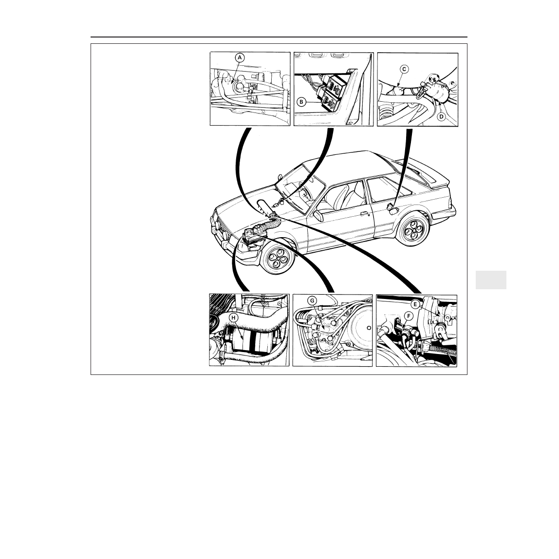
1.5 K-Jetronic system main
component locations
A Warm-up regulator
B Speed sensing module
C Fuel accumulator (early model location)
D Fuel pump
E Throttle housing
F Cold start valve
G Fuel distributor
H Fuel filter
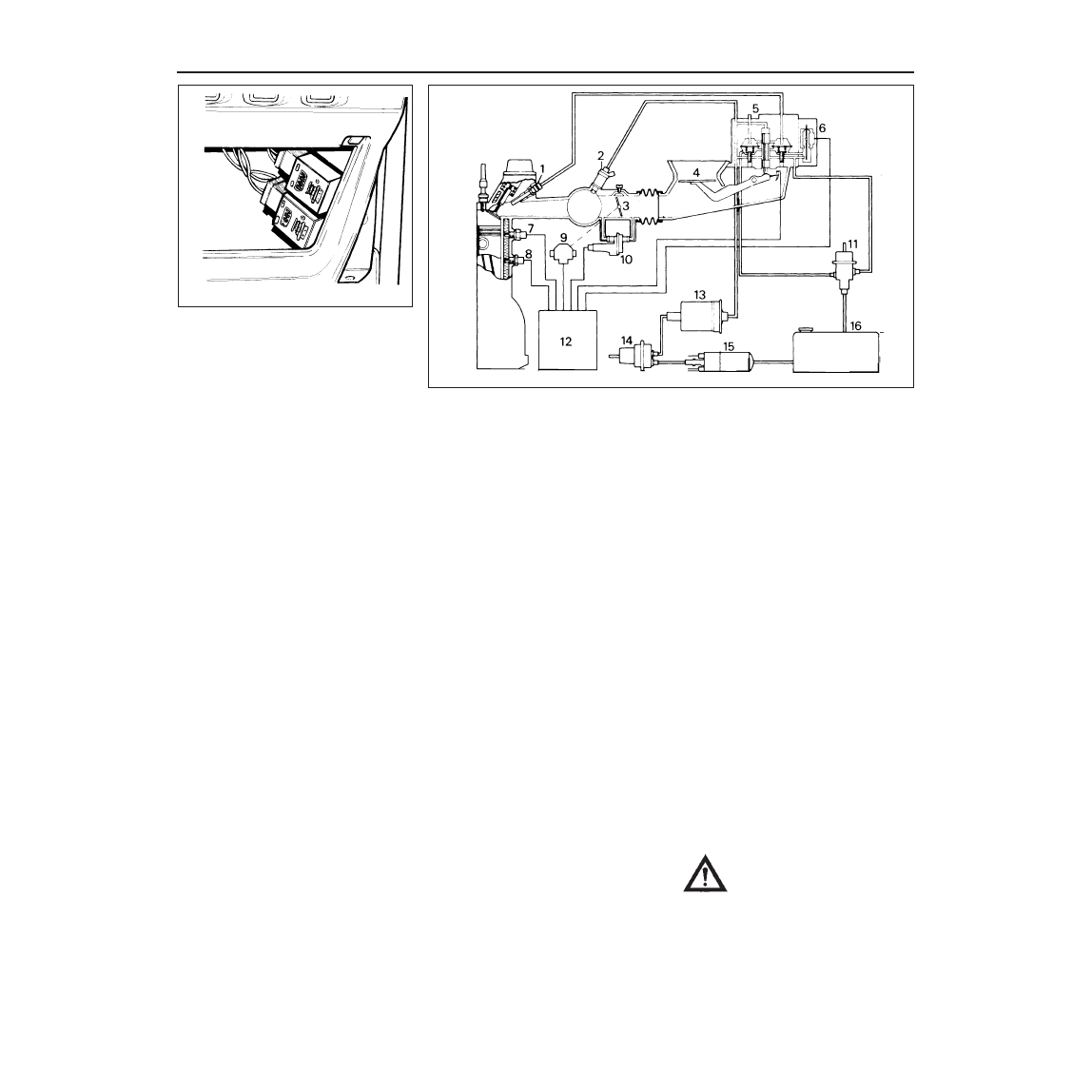
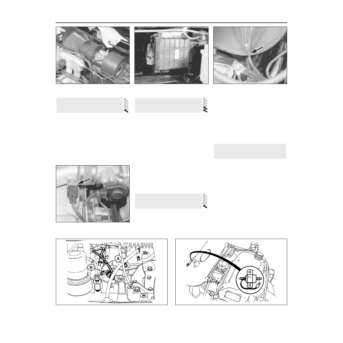
The safety module is located under the
facia panel on the driver’s side and is
coloured purple (see illustration). Its purpose
is to shut off the power supply to the fuel
pump should the engine stall or the vehicle be
involved in an accident. The module senses
ignition pulses, and cuts the fuel supply if the
ignition pulses stop.
The fuel shut-off valve system is an
economy device whereby air is drawn from
within the air cleaner unit through the shut-off
valve and directed into the ducting chamber
above the air sensor plate causing a
depression. This then causes the sensor plate
to drop which, in turn, shuts off the fuel
supply. The valve is operated by signals from
a coolant temperature sensor and a throttle
position sensor. The shut-off valve will only
operate under the following circumstances:
a) When the engine coolant temperature is
at or above 35°C (95°F)
b) When the throttle is closed and with the
engine speed decelerating from speeds
above 1600 rpm
The engine speed is sensed by a speed
sensing module which is coloured black and
located beneath the facia panel on the driver’s
side.
Bosch KE-Jetronic system
The Bosch KE-Jetronic fuel-injection
system is fitted to Escort RS Turbo models
and is a further development of the K-Jetronic
system.
Apart from minor alterations the basic
principles of the hydraulics and mechanics
used on the K-Jetronic system are unchanged
on the KE-Jetronic system. The main
difference between the two types is that on the
KE-Jetronic system all mixture corrections are
controlled electronically by an electromagnetic
pressure actuator incorporated in the fuel
distributor. The pressure actuator is directly
controlled by a variable electric current
delivered by the fuel-injection control module.
This module receiver inputs from the various
engine sensors concerning engine
temperature, engine load, throttle shift, throttle
position and starter actuation. This information
modifies a program stored in the module
memory so that the electromagnetic pressure
actuator, on receiving the signal from the
module, can alter the mixture to suit all engine
operating conditions. This renders the control
pressure circuit and warm-up regulator of the
K-Jetronic system unnecessary, and also
undertakes the functions of the fuel shut-off
valve, safety module and speed sensing
module (see illustration).
Precautions
Due to the complexity of the fuel-injection
system, and the need for special tools and
test equipment, any work should be limited to
the operations described in this Chapter.
Other adjustments and system checks are
beyond the scope of most readers and should
be left to a Ford dealer.
Before disconnecting any fuel lines, unions
or components thoroughly clean the
component or connection and the adjacent
area.
Place any removed components on a clean
surface and cover them with plastic sheet or
paper. Do not use fluffy rags for cleaning.
The system operates under pressure at all
times and care must be taken when
disconnecting fuel lines. Relieve the system
pressure as described in the relevant Section
before disconnecting any fuel lines under
pressure. Refer to the warning note at the end
of this Section, and always work with the
battery negative lead disconnected and in a
well ventilated area.
When working on the KE-Jetronic system
the following additional precautions must be
observed:
a) Never start the engine when the battery is
not firmly connected.
b) Never disconnect the battery when the
engine is running.
c) If the battery is to be rapid charged from
an external source it should be completely
disconnected from the vehicle electrical
system.
d) The KE-Jetronic control unit must be
removed from the car if temperatures are
likely to exceed 80°C (176°F) as would be
experienced, for example, in a paint spray
oven or if any electric welding is being
carried out on the car.
e) The ignition must be switched off when
removing the control unit.
4B•4 Bosch K and KE fuel injection systems
1.16 K-Jetronic system speed sensing
module and fuel pump safety module
locations
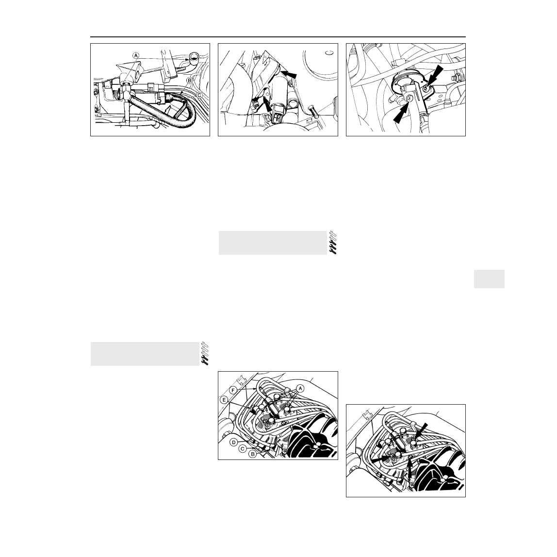
1.19 KE-Jetronic fuel-injection system layout and components
1 Injector
2 Cold start valve
3 Throttle plate
4 Sensor plate
5 Fuel distributor
6 Electro-magnetic pressure actuator
7 Thermo-time switch
8 Temperature sensor
9 Throttle position switch
10 Auxiliary air device
11 Pressure regulator
12 Control module
13 Fuel filter
14 Fuel accumulator
15 Fuel pump
16 Fuel tank
Warning: Many of the procedures
in this Chapter entail the removal
of fuel pipes and connections
which may result in some fuel
spillage. Before carrying out any operation
on the fuel system refer to the precautions
given in Safety First! at the beginning of
this manual and follow them implicitly.
Petrol is a highly dangerous and volatile
liquid and the precautions necessary when
handling it cannot be overstressed
K-Jetronic system
Removal
1 Remove the air cleaner element as
described in Chapter 1.
2 Detach the fuel filter from the side of the
cleaner casing (leave the fuel lines attached to
the filter) and the air inlet hose from the front
end of the case.
3 Unscrew and remove the casing retaining
nuts from the inner wing panel and lift out the
casing.
Refitting
4 Refitting is the reversal of the removal
procedure. Refit the air cleaner element as
described in Chapter 1.
KE-Jetronic system
Removal
5 Undo the two bolts securing the air cleaner
assembly to the air sensor plate unit and
remove the air cleaner assembly (see
illustration).
Refitting
6 Refit the unit to the air sensor plate and
secure with the two bolts.
The procedures are the same as described
in Part A of this Chapter for carburettor
engines, but in addition disconnect the fuel
tank-to-fuel pump hose from the rear face of
the tank.
Adjustment
The procedure is the same as described in
Part A of this Chapter for carburettor engines,
except that the cable adjuster is situated in a
bracket alongside the throttle housing.
Removal and refitting
The procedure is the same as described in
Part A of this Chapter for carburettor engines,
except that it is not necessary to remove the
air cleaner, and the location of the mounting
bracket is alongside the throttle housing.
The procedure is the same as described in
Part A of this Chapter for carburettor models.
Note: Refer to the precautions at the end of
Section 1 before proceeding.
Removal
1 The fuel pump is bolted to the underside of
the car just to the rear of the fuel tank. For
access raise and support the car securely at
the rear.
2 Disconnect the battery earth lead.
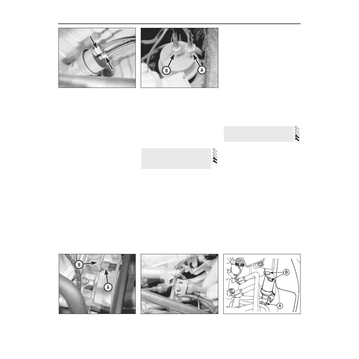
3 On the K-Jetronic system relieve the
system pressure by slowly loosening the fuel
feed pipe union at the warm-up regulator (see
illustration). Absorb the fuel leakage in a
cloth.
4 On the KE-Jetronic system relieve the
system pressure by slowly loosening the cold
start valve union on the top of the fuel
distributor (see illustration). Absorb fuel
leakage in a cloth.
5 Clamp the fuel inlet hose midway between
the tank and the pump using a brake hose
clamp, self-locking grips or similar. If the fuel
level in the tank is low you may prefer to drain
the fuel from the tank into a suitable container
once the inlet hose is disconnected.
6 Disconnect the fuel inlet and outlet pipes
from the pump, catching fuel spillage in a
suitable container (see illustration). Once
disconnected do not allow dirt to enter the
pipes, temporarily plug or seal them if
necessary.
7 Note the electrical connections to the pump
and disconnect them.
8 Loosen the pump bracket retaining bolt and
then withdraw the pump unit with rubber
protector sleeve.
Refitting
9 Refitting of the fuel pump is a reversal of
the removal procedure. Renew the feed pipe
from the tank if it is damaged or defective.
10 Check that the rubber protector sleeve is
correctly positioned round the pump before
tightening the clamp nut.
11 On completion, tighten the warm-up
regulator or cold start valve fuel unions,
reconnect the battery earth lead, start the
engine and check for any fuel leaks.
Note: Refer to the precautions at the end of
Section 1 before proceeding.
Pre-1986 models
Removal
1 The fuel accumulator is mounted adjacent
to the fuel pump, above the rear left-hand
suspension arm.
2 Disconnect the battery negative lead.
7 Fuel accumulator - removal
and refitting
6 Fuel pump - removal and
refitting
5 Accelerator pedal - removal
and refitting
4 Throttle cable - adjustment,
removal and refitting
3 Fuel tank - removal and refitting
2 Air cleaner - removal and
refitting
Bosch K and KE fuel injection systems 4B•5
4B
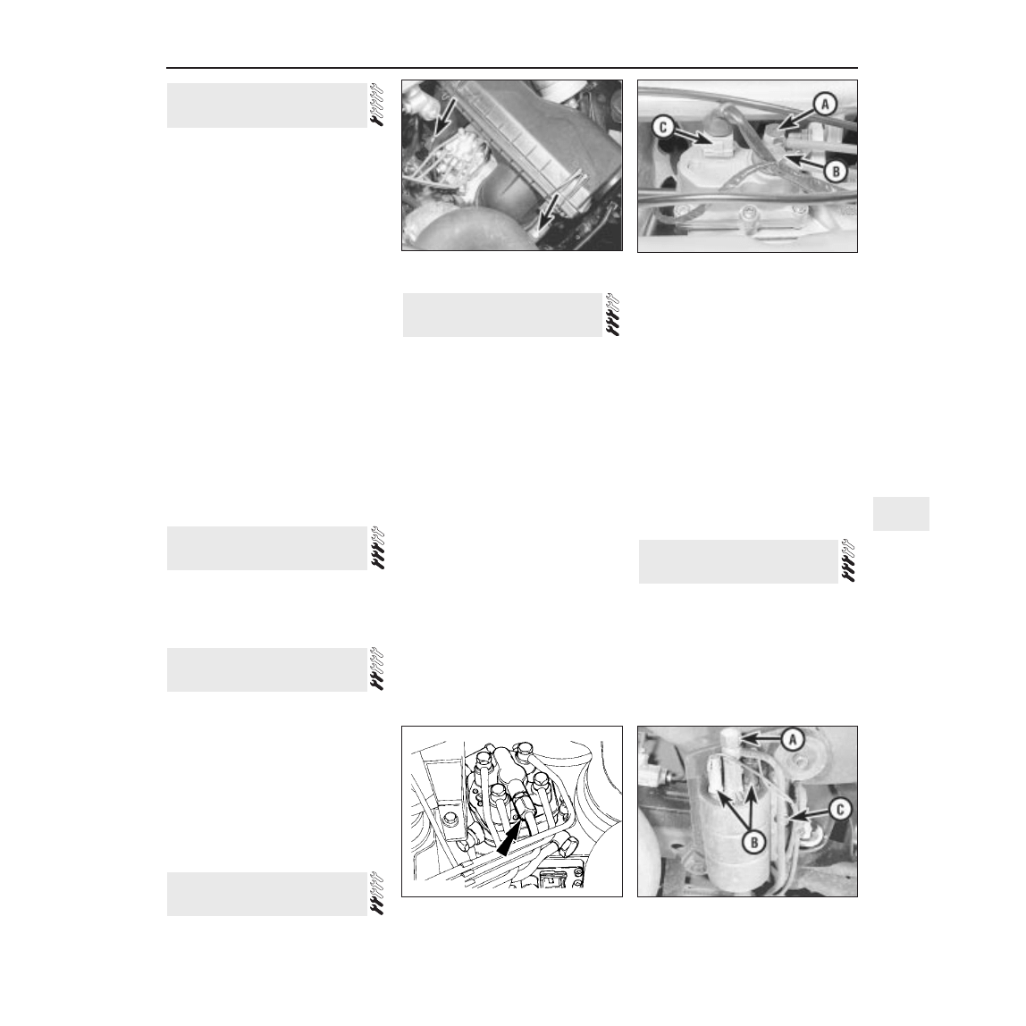
2.5 KE-Jetronic air cleaner retaining bolts
(arrowed)
6.3 Warm-up regulator fuel feed pipe (A),
outlet pipe (B) and wiring multi-plug (C)
6.4 KE-Jetronic system cold start valve
pipe union (arrowed) on fuel distributor
6.6 Fuel pump outlet pipe (A), electrical
connections (B) and pump bracket
retaining bolt (C)
3 Raise the rear of the car and support it on
axle-stands (see “Jacking and Vehicle
Support”).
4 Relieve the system pressure by slowly
loosening the fuel feed pipe at the warm-up
regulator. Absorb fuel leakage in a cloth.
5 Disconnect the fuel pipes from the fuel
accumulator and catch the small quantity of
fuel which will be released (see illustration).
6 Remove the clamp screw and remove the
accumulator.
Refitting
7 Refitting is a reversal of removal. Check for
leaks on completion (with the engine
restarted).
1986 models onwards
Removal
8 On later models with K-Jetronic and KE-
Jetronic systems the fuel accumulator is
located in the engine compartment behind the
fuel distributor.
9 Disconnect the battery negative lead.
10 For access remove the air cleaner as
described in Section 2.
11 Relieve the system pressure by slowly
loosening the cold start valve union on the top
of the fuel distributor (see illustration 6.4).
Absorb fuel leakage in a cloth.
12 Disconnect the fuel pipes from the
accumulator and catch the small quantity of
fuel which will be released (see illustration).
13 Remove the clamp screw and remove the
accumulator.
Refitting
14 Refitting is a reversal of removal. Check
for leaks on completion (with the engine
restarted).
Note: Refer to the precautions at the end of
Section 1 before proceeding. It is important to
note that each injection supply pipe
connection in the distributor head has a screw
adjacent to it. These four screws are not for
adjustment and must not be removed or have
their settings altered. New O-ring seals must
be used on refitting.
Removal
1 Disconnect the battery earth lead.
2 Detach the four supply pipes from the
injectors, and use a rag to collect any spilled
fuel.
3 Unscrew and remove the respective
injector retaining bracket bolts, then withdraw
the injectors and their O-ring seals (see
illustration).
4 The injector fuel delivery pipes can be
removed by unscrewing and removing the
four banjo bolts at the distributor head. Note
the respective pipe connections as they are
detached and remove the pipes complete
with the plastic hoses and the injector
harness. Do not separate the pipes or hoses
from the injector harness.
5 Before reassembling the fuel delivery pipes,
or the injectors, clean all pipe connections
thoroughly and use new O-ring seals on the
injectors. Use new seal washers on the banjo
connections fitting two washers (one each
side) per union. Do not overtighten the banjo
bolts, or the washers may fracture.
Refitting
6 Refitting of the injectors and the fuel delivery
pipes is otherwise a reversal of the removal
procedure. On completion check that the pipes
and hoses are not distorted and when the
engine is restarted check for any signs of leaks.
Note: Refer to the precautions at the end of
Section 1 before proceeding.
K-Jetronic system
Removal
1 Disconnect the battery earth lead.
2 Detach the electrical wiring multi-plug from
the valve (see illustration).
3 Slowly unscrew and remove the fuel supply
pipe banjo bolt. Take care on removal, as the
system will be under pressure. Soak up fuel
spillage with a cloth.
4 Unscrew and remove the two socket-head
mounting bolts using an Allen key or Torx type
key or socket bit on later models, and remove
the valve.
Refitting
5 Refitting is a reversal of the removal
procedure. Do not overtighten the banjo bolt
or the washers may fracture (use a new one
each side of the union).
6 On completion restart the engine and check
for signs of fuel leakage.
9 Cold start valve - removal and
refitting
8 Fuel injectors and injector
delivery pipes - removal and
refitting
4B•6 Bosch K and KE fuel injection systems
7.5 Fuel pipe connections (arrowed) at the
underbody mounted fuel accumulator
7.12 Fuel inlet pipe (A) and outlet pipe (B)
at the engine compartment mounted fuel
accumulator
8.3 Injector fuel pipe union (A) and
retaining bracket bolt (B)
9.2 Disconnecting the cold start valve
wiring multi-plug
9.8 KE-Jetronic system cold start valve
location
A Fuel pipe union
B Retaining bolts
KE-Jetronic system
Removal
7 Disconnect the battery earth lead.
8 Disconnect the wiring multi-plug from the
valve which is located underneath the throttle
housing (see illustration).
9 Slowly unscrew and remove the fuel supply
pipe banjo union. Take care on removal, as
the system will be under pressure. Soak up
fuel spillage with a cloth.
10 Unscrew and remove the two Torx type
mounting bolts using a Torx key or socket bit.
Remove the valve from under the throttle
housing.
Refitting
11 Refitting is a reversal of removal. Do not
overtighten the banjo bolt or the washers may
fracture (use a new one each side of the
union).
12 On completion restart the engine and
check for leaks.
K-Jetronic system
Removal
1 Disconnect the battery earth lead.
2 Disconnect the wiring multi-plug and the
two air hoses from the device which is located
beneath the cold start valve (see illustration).
3 Undo the two Torx type retaining bolts
using a Torx key or socket bit and lift the unit
away (see illustration).
Refitting
4 Refitting is a reversal of removal.
KE-Jetronic system
Removal
5 Apply the handbrake, jack up the front of
the car and support it on axle stands (see
“Jacking and Vehicle Support”).
6 Disconnect the battery negative lead.
7 Disconnect the auxiliary air device wiring
multi-plug and the two air hoses.
8 Undo the two Torx type retaining bolts
using a Torx key or socket bit and remove the
unit from under the inlet manifold (see
illustration).
Refitting
9 Refitting is a reversal of removal.
Note: Refer to the precautions at the end of
Section 1 before proceeding. It is important to
note that each injection supply pipe connection
in the distributor head has a screw adjacent to
it. These four screws are not for adjustment and
must not be removed or have their settings
altered. A new O-ring and new banjo union
sealing washers will be required on refitting.
K-Jetronic system
Removal
1 Disconnect the battery negative lead.
2 Relieve the system pressure by slowly
loosening the fuel feed pipe union at the
warm-up regulator (see illustration 6.3).
Absorb the fuel leakage in a cloth.
3 Disconnect the four injector feed pipes, the
fuel inlet and return pipes, and the warm-up
regulator feed and return pipe banjo unions at
the fuel distributor (see illustration). Note the
sealing washers on each side of the banjo
unions which must be renewed on reconnection
of the pipes. Take care not to allow dirt to enter
the pipes or their connection ports.
4 Unscrew the three retaining screws from
the fuel distributor top face and remove the
unit from the car (see illustration). Recover
the sealing O-ring.
Refitting
5 Refitting is a reversal of removal, but ensure
perfectly clean mating faces and use a new
sealing O-ring and new washers for the banjo
unions. Check for any signs of leaks on
completion and adjust the idle speed and
mixture settings as described in Chapter 1.
6 The main system fuel pressure should be
checked and if necessary adjusted by a Ford
dealer to ensure satisfactory running of the
system.
KE-Jetronic system
Removal
7 Disconnect the battery negative lead.
8 Relieve the system pressure by slowly
loosening the cold start valve union on the top
of the fuel distributor (see illustration 6.4).
Absorb fuel leakage in a cloth.
11 Fuel distributor - removal and
refitting
10 Auxiliary air device - removal
and refitting
Bosch K and KE fuel injection systems 4B•7
4B
10.2 K-Jetronic system auxiliary air device
connections
A Throttle housing hose
B Cold start valve hose
C Wiring multi-plug
10.3 K-Jetronic system auxiliary air device
retaining bolt locations
10.8 KE-Jetronic system auxiliary air
device retaining bolts
11.3 K-Jetronic fuel distributor pipe
connections
A To injectors
B To cold start valve
C Fuel return
D From warm-up
regulator
E Fuel inlet
F To warm-up
regulator
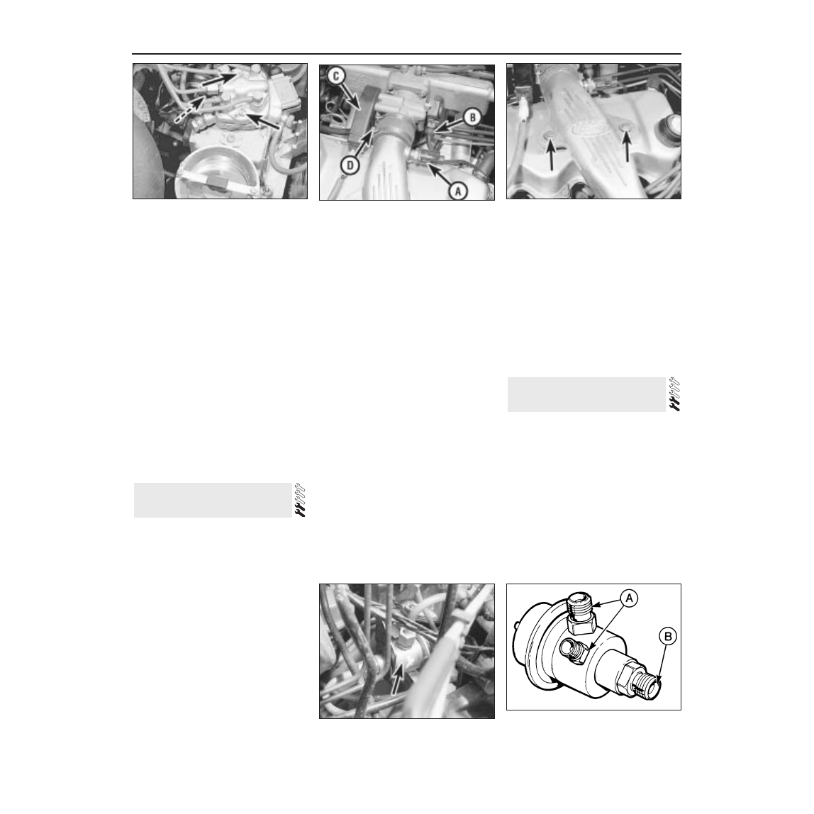
11.4 K-Jetronic system fuel distributor
retaining screws (arrowed)
9 Disconnect the four injector feed pipes, the
cold start valve pipe and union adapter, the
fuel inlet pipe and pressure regulator return
pipe from the fuel distributor. Note the sealing
washers on each side of the banjo unions
which must be renewed on reconnection of
the pipes. Take care not to allow dirt to enter
the pipes or their connection parts.
10 Disconnect the wiring multi-plug from the
pressure actuator on the side of the fuel
distributor.
11 Undo the retaining screws and remove
the fuel distributor (see illustration). Recover
the sealing O-ring.
Refitting
12 Refitting is a reversal of removal, but
ensure perfectly clean mating faces and use a
new sealing O-ring and new washers for the
banjo unions. Check for any signs of leaks on
completion and adjust the idle speed and
mixture settings as described in Chapter 1.
Note: During manufacture the throttle plate is
adjusted so that it is fractionally open, to avoid
the possibility of it jamming shut, and it must
not be repositioned. Idle speed adjustment is
provided for by means of a screw which,
according to its setting, restricts the airflow
through the air bypass channel in the throttle
housing.
K-Jetronic system
Removal
1 Disconnect the battery negative lead.
2 Slacken the retaining screw and detach the
inlet air hose from the throttle housing.
3 Disconnect the accelerator cable at the
housing linkage with reference to Section 4.
4 Disconnect the distributor vacuum hose
and auxiliary air hose from the underside of
the throttle housing.
5 Undo the four nuts and carefully withdraw
the throttle housing from the manifold studs.
Refitting
6 Refitting is a reversal of removal, but ensure
that the mating faces are perfectly clean.
Renew the gaskets, one on each side of the
insulator block, if necessary.
7 On completion adjust the idle speed as
described in Chapter 1.
KE-Jetronic system
Removal
8 Disconnect the battery negative terminal.
9 Disconnect the charge air temperature
sensor and throttle position sensor wiring
multi-plugs (see illustration).
10 Slacken the hose clip and detach the air
inlet hose from the inlet duct.
11 Undo the two bolts securing the inlet duct
to the rocker cover slacken the throttle
housing connecting hose clip and remove the
inlet duct (see illustration).
12 Extract the retaining clip and disconnect
the throttle cable end from the linkage ball-
stud.
13 Undo the two bolts and remove the
throttle cable bracket from the throttle
housing.
14 Disconnect the auxiliary air hose, then
undo the four nuts and remove the throttle
housing.
15 Do not remove the throttle position sensor
from the throttle housing unless absolutely
necessary. If it must be removed, mark its
position for refitting and then have it
accurately adjusted by a Ford dealer on
completion. This will also be necessary if the
sensor or throttle housing are renewed.
Refitting
16 Refitting is the reversal of removal, but
use a new gasket and ensure clean mating
faces. After refitting adjust the idle speed as
described in Chapter 1.
Note: Refer to the precautions at the end of
Section 1 before proceeding.
Removal
1 The fuel pressure regulator is only used on
KE-Jetronic systems and is located behind
the fuel distributor (see illustration).
2 Disconnect the battery negative lead.
3 Relieve the system pressure by slowly
loosening the cold start valve union on the top
of the fuel distributor (see illustration 6.4).
Absorb fuel leakage in a cloth.
4 Place absorbent cloth beneath the
regulator and undo the two fuel feed unions
and the fuel return union. Note the pipe
locations to ensure correct refitting.
13 Fuel pressure regulator -
removal and refitting
12 Throttle housing - removal
and refitting
4B•8 Bosch K and KE fuel injection systems
11.11 KE-Jetronic fuel distributor retaining
screws (arrowed)
12.9 Component attachments at the
KE-Jetronic throttle housing
A Charge air temperature sensor multi-plug
B Throttle position sensor wiring multi-plug
C Throttle cable bracket
D Connecting hose retaining clip
12.11 Air inlet duct retaining bolts
(arrowed)
13.1 KE-Jetronic fuel pressure regulator
location (arrowed) behind fuel distributor
13.6 KE-Jetronic fuel pressure regulator
pipe connections
A Fuel feed
B Fuel return
5 Remove the securing tie and withdraw the
regulator from its bracket.
Refitting
6 Refitting is a reversal of removal. Ensure
that all unions are correctly reconnected and
secure, and on completion check for fuel leaks
with the engine running (see illustration).
Note: Refer to the precautions at the end of
Section 1 before proceeding. New banjo
union sealing washers must be used on
refitting.
Removal
1 The warm-up regulator is only used on K-
Jetronic systems and is situated on the inlet
manifold just to the rear of the rocker cover.
2 Disconnect the battery negative lead.
3 Relieve the system pressure by slowly
loosening the fuel feed pipe union at the
warm-up regulator (see illustration 6.3).
Absorb the fuel leakage in a cloth.
4 After relieving the system pressure
disconnect the fuel feed union completely,
followed by the outlet union. Recover the
sealing washers used on each side of the
unions.
5 Disconnect the regulator wiring multi-plug.
6 Undo the two Torx type screws using a
suitable Torx key or socket bit and remove the
regulator from its location (see illustration).
Refitting
7 Refitting is a reversal of removal, but use
new sealing washers on each side of the banjo
unions and apply a thread-locking compound
to the Torx retaining bolts. On completion
check for leaks with the engine running.
Note: Refer to the precautions at the end of
Section 1 before proceeding. New O-rings
must be used on refitting.
Removal
1 The electro-magnetic pressure actuator is
only used on KE-Jetronic systems and is
located on the side of the fuel distributor.
2 Disconnect the battery negative lead.
3 Remove the air cleaner as described in
Section 2.
4 Relieve the system pressure by slowly
loosening the cold start valve union on the top
of the fuel distributor (see illustration 6.4).
Absorb fuel leakage in a cloth.
5 Disconnect the wiring multi-plug, then undo
the two screws securing the actuator to the
fuel distributor (see illustration). Remove the
unit and the sealing O-rings.
Refitting
6 Refitting is the reverse sequence to
removal, but ensure both mating faces are
clean. New O-rings must be used and care
taken not to displace them when fitting. On
completion check for fuel leaks with the
engine running.
Removal
1 The fuel-injection control module is only
used on KE-Jetronic systems and is located in
the engine compartment behind the heater
plenum chamber and fan motor.
2 Disconnect the battery negative lead.
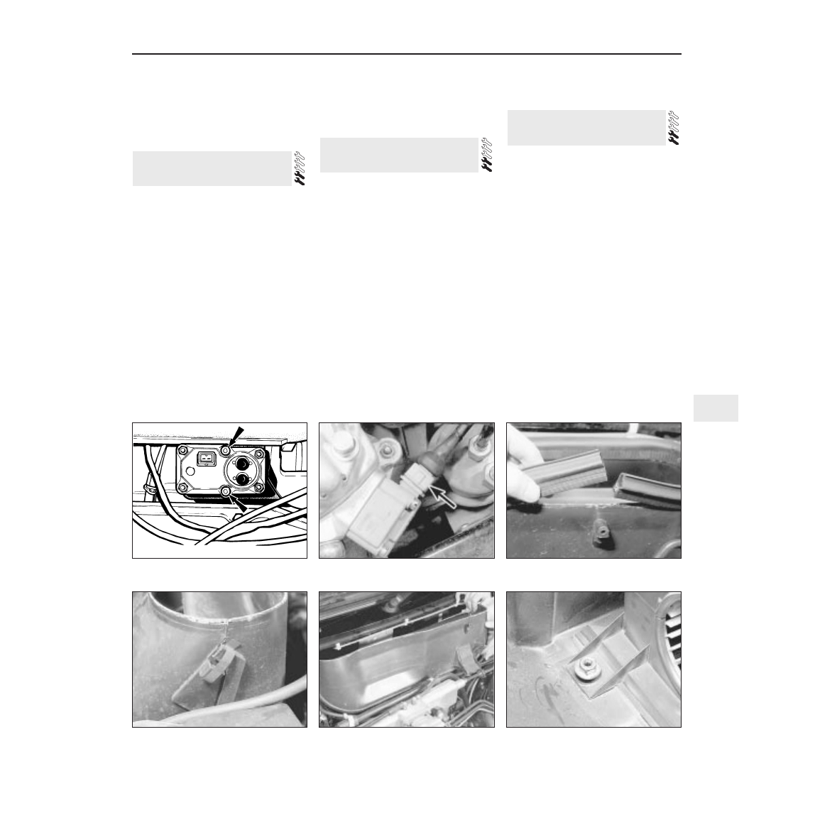
3 Remove the plenum chamber top cover
rubber seal (see illustration).
4 Release the five retaining clips and lift off
the plenum chamber top cover (see
illustrations).
5 Undo the two nuts securing the heater fan
motor assembly to the bulkhead. Lift the unit
off the studs and place it on the engine, but
avoid straining the wiring (see illustrations).
6 Disconnect the module wiring multi-plug,
then undo the three screws and remove the
unit from its location (see illustration).
Refitting
7 Refitting is the reversal of removal. Take
care not to trap the motor wiring when refitting
the fan motor assembly and ensure that it is
engaged in the slot provided in the housing
(see illustration).
16 Fuel-injection control module
- removal and refitting
15 Electro-magnetic pressure
actuator - removal and refitting
14 Warm-up regulator - removal
and refitting
Bosch K and KE fuel injection systems 4B•9
4B
14.6 K-Jetronic system warm-up regulator
retaining screws
15.5 Pressure actuator wiring multi-plug
(arrowed)
16.3 Remove the plenum chamber rubber
seal
16.4a Release the retaining clips . . .
16.4b . . . and lift off the plenum chamber
top cover
16.5a Heater fan motor retaining nut
Removal
1 The charge air temperature sensor is only
used on KE-Jetronic systems and is located in
the air inlet duct (see illustration).
2 Disconnect the battery negative lead.
3 Disconnect the wiring multi-plug and
unscrew the sensor from its location.
Refitting
4 Refitting is the reversal of removal.
Removal
1 Disconnect the battery negative lead.
2 Drain the cooling system as described in
Chapter 1.
3 Raise the front of the car and support it on
axle stands (see “Jacking and Vehicle
Support”).
4 Disconnect the wiring multi-plug from the
thermo-time switch located on the inlet
manifold intermediate flange and accessible
from under the car (see illustration).
5 Unscrew the unit and remove it from its
location.
Refitting
6 Refitting is a reversal of removal. Refill the
cooling system as described in Chapter 1.
Removal
1 The idle speed compensator is only fitted to
K-Jetronic systems from 1986 onwards and is
located in the centre of the engine
compartment bulkhead (see illustration).
2 Disconnect the battery negative lead.
3 Disconnect the electrical lead, undo the two
screws and withdraw the unit. Detach the air
hoses from each end and remove the
compensator.
Refitting
4 Refitting is a reversal of removal. The air
hoses can be connected to either end and the
arrows on the unit can be ignored.
Escort RS Turbo models are equipped with
an exhaust driven turbocharger, which is a
device designed to increase the engine’s
power output without increasing exhaust
emissions or adversely affecting fuel
economy. It does so by utilising the heat
energy present in the exhaust gases as they
exit the engine.
Basically the turbocharger consists of two
fans mounted on a common shaft. One fan is
driven by the hot exhaust gases as they rush
through the exhaust manifold and expand.
The other draws in fresh air and compresses it
before it enters the inlet manifold. By
compressing the air, a larger charge can be let
into each cylinder and greater power output is
achieved.
20 Turbocharger - general
description
19 Idle speed compensator -
removal and refitting
18 Thermo-time switch -
removal and refitting
17 Charge air temperature
sensor - removal and refitting
4B•10 Bosch K and KE fuel injection systems
16.5b Removing the heater fan motor
assembly . . .
16.6 . . . for access to the fuel-injection
control module
16.7 Fan motor wiring engaged in housing
slot (arrowed)
17.1 Charge air temperature sensor
location (arrowed)
18.4 Thermo-time switch (A) and temperature sensor (B) on the
KE-Jetronic system (viewed from under the car)
19.1 K-Jetronic system idle speed compensator location
The temperature of the inlet air is reduced,
thus increasing its density, by passing it
through an intercooler, mounted alongside the
radiator, prior to it entering the manifold.
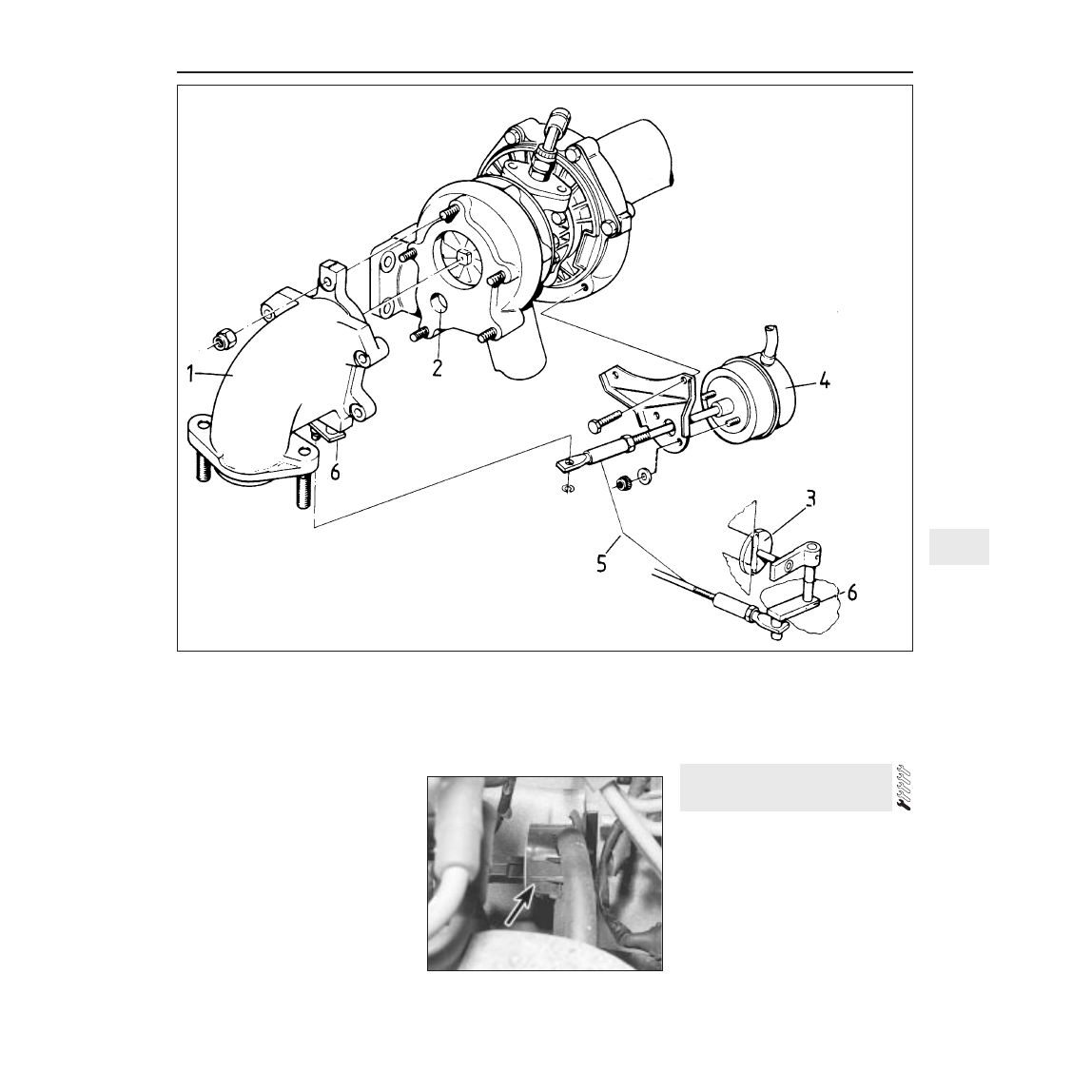
The boost pressure generated by the
turbocharger is controlled by a waste gate
which when open allows a high proportion of
the exhaust gases to bypass the turbocharger
and directly enter the exhaust system (see
illustration). The turbocharger therefore loses
speed and boost pressure is reduced.
The waste gate is opened and closed by
the waste gate actuator through an actuator
rod. The waste gate actuator is in turn
controlled by the solenoid control valve which
receives signals in the form of a pulsed
voltage from the ignition system. Electronic
Spark Control module (see Chapter 5, Part B).
The Electronic Spark Control module receives
data from various engine sensors, particularly
the charge air temperature sensor in the inlet
air duct, which modify the module program to
suit all operating conditions. he module then
signals the solenoid control valve to open or
close the waste gate via the waste gate
actuator.
Lubrication oil for the turbocharger is taken
from the engine lubricating circuit via a special
branch line. The turbocharger shaft rotates in
plain bearings through which a relatively large
amount of oil is allowed to pass. Therefore
when rotating, the shaft floats on a thick film
of lubricating oil.
The turbocharger is a close tolerance,
expensive component and servicing or repairs
should be left to a dealer service department
or specialist with turbocharger repair
experience. Apart from the information in the
following Sections, any other work on the
turbocharger or its related components is
beyond the scope of the average reader.
Removal
1 The solenoid control valve is mounted on a
bracket located underneath the ignition
distributor
(see illustration).
2 Disconnect the battery negative lead.
3 Disconnect the solenoid wiring multi-plug.
4 Identify and mark the hose locations at the
solenoid connections, then remove the hoses.
5 Undo the retaining screws and remove the
unit from its location.
Refitting
6 Refitting is a reversal of removal.
21 Waste gate solenoid control
valve - removal and refitting
Bosch K and KE fuel injection systems 4B•11
4B
21.1 Waste gate solenoid control valve
location (arrowed)
20.4 Turbocharger and waste gate
components
1 Turbocharger exhaust manifold and
waste gate housing
2 Bypass duct
3 Waste gate
4 Waste gate actuator
5 Actuator rod
6 Waste gate lever
1985 models
Removal
1 Disconnect the battery negative lead.
2 Remove the air cleaner as described in
Section 2.
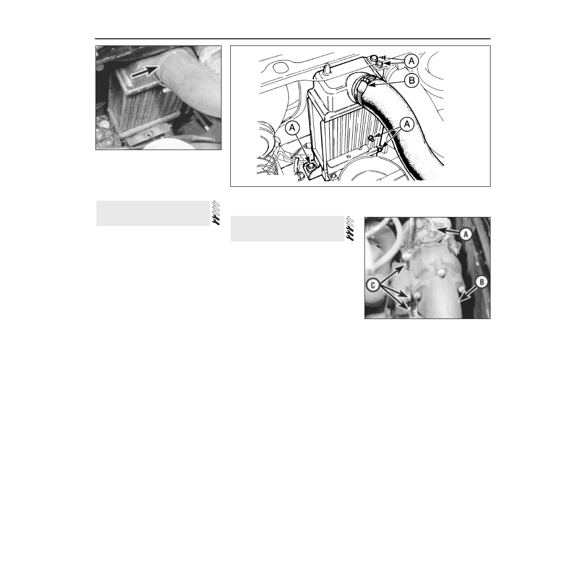
3 Remove the intercooler upper and lower air
hoses (see illustration).
4 Undo the upper retaining bolt, tilt the
intercooler towards the engine at the top and
lift up to disengage the lower retaining pins.
Remove the unit from the engine compartment.
Refitting
5 Refitting is a reversal of removal.
1986 models onwards
Removal
6 Proceed as described in paragraphs 1 to 3.
7 Undo the two radiator and intercooler lower
retaining bolts (see illustration).
8 Move the radiator and intercooler assembly
towards the engine and undo the four bolts
securing the intercooler to the radiator.
9 Undo the retaining bolt and move the horn
nearest to the intercooler to one side.
10 Withdraw the intercooler from the engine
compartment.
Refitting
11 Refitting is a reversal of removal.
Note: New gaskets and new tabwashers must
be used on refitting.
Removal
1 Disconnect the battery negative lead.
2 Disconnect the turbocharger inlet and
outlet air hoses and the hoses from the waste
gate actuator and solenoid control valve at
their turbocharger connections. Tape over all
the disconnected unions and outlets to
prevent dirt ingress.
3 Support the exhaust system and
disconnect it from the turbocharger exhaust
manifold .
4 Disconnect the oil feed union on the top of
the turbocharger and the oil return line from
underneath the unit (see illustration). Tape
over all disconnected pipes and unions.
5 Bend up the tabwashers, then unscrew the
nuts securing the turbocharger to the exhaust
manifold. Remove the unit and store it in a
clean plastic bag while removed from the car.
Refitting
6 Before refitting the turbocharger ensure
that all mating faces are clean and obtain new
gaskets and a set of new tabwashers. It is
also advisable to renew the engine oil and
filter, particularly if a new turbocharger is
being fitted or if there was any sign of
previous oil contamination.
7 Refitting is a reversal of removal, but
bearing in mind the following points:
a) Tighten all retaining nuts to the specified
torque and secure with the tabwashers.
b) Before connecting the oil feed union,
prime the turbocharger bearings by
injecting clean engine oil into the union
orifice.
c) Crank the engine over on the starter with
the ignition LT lead at the coil
disconnected until the oil pressure
warning light goes out.
23 Turbocharger- removal and
refitting
22 Intercooler - removal and
refitting
4B•12 Bosch K and KE fuel injection systems
22.7 Intercooler mountings and attachments - 1986 models onwards
23.4 Turbocharger oil feed union (A),
turbocharger exhaust manifold (B) and
retaining nuts (C)
A Retaining bolts
B Upper air hose
22.3 Intercooler upper air hose
attachment (arrowed)
Wyszukiwarka
Podobne podstrony:
Gasoline Fuel Injection System K Jetronic
Bmw e12 5 Series L Jetronic Fuel Injection Systems
Fuel Injection Systems Bosch Cis
Mechanics of a Diesel Fuel Injection System
Fuel injection ASZ
SMeyer CA2067735A1 Water Fuel Injection System
How to configure fuel injectors on the pre CAN Duratorq HPCR
Commensal Bacteria, Redox Stress, and Colorectal Cancer Mechanisms and Models
Self Study Programme 351 Common rail fuel injection system fitted in the 3 0l V6 TDI engine
LR Fuel InjectionSystems
Curcumin improves learning and memory ability and its neuroprotective mechanism in mice
Simultaneous determination of rutin and ascorbic acid in a sequential injection lab at valve system
Fuel injection
FIDE Trainers Surveys 2013 05 21, Jeroen Bosch Training and Solitaire Chess
Audi A8 4,2 fuel injection engine ENG
Samurai Mechanical Fuel Pump Problems Diagnosing mechanical fuel pump problems
Wtrysk mechaniczny K-Jetronic, Troche techniki E30 i nietylko
więcej podobnych podstron