
LAND ROVER FUEL INJECTION SYSTEMS
Introduction
63
LAND ROVER FUEL INJECTION SYSTEMS
INTRODUCTION
Land Rover vehicles use one of two types of electronically controlled fuel injection systems:
Multiport Fuel Injection (MFI) or Sequential Multiport Fuel Injection (SFI).
MULTIPORT FUEL INJECTION (MFI)
Multiport Fuel Injection (MFI) is found on Land Rover models using the Lucas 13 CU, 14 CU,
and 14 CUX engine management systems.
Applications:
• 13CU
1987-1988 Range Rover Classic
• 14CU
1989 Range Rover Classic
• 14CUX
1990-1995 Range Rover Classic
1994-1995 Discovery
1993 Defender 110
1994-1995 Defender 90
SEQUENTIAL MULTIPORT FUEL INJECTION (SFI)
Sequential Multiport Injection (SFI) is used on vehicles equipped with the Sagem/Lucas Generic
Engine Management System (GEMS), and the Bosch Motronic M5.2.1 engine management
system.
Applications:
• GEMS
1995-early 1999 Range Rover
1996-early 1999 Discovery
1997 Defender 90
• Bosch Motronic 5.2.1
1999- Range Rover
1999- Discovery Series II
LAND ROVER FUEL INJECTION SYSTEMS
64
LAND ROVER FUEL SYSTEM COMPONENTS
The following section will provide an overview and comparison of Land Rover fuel system
components in use since 1987. These components will be discussed in the order of Engine
Control Module, System Outputs, and System Inputs.
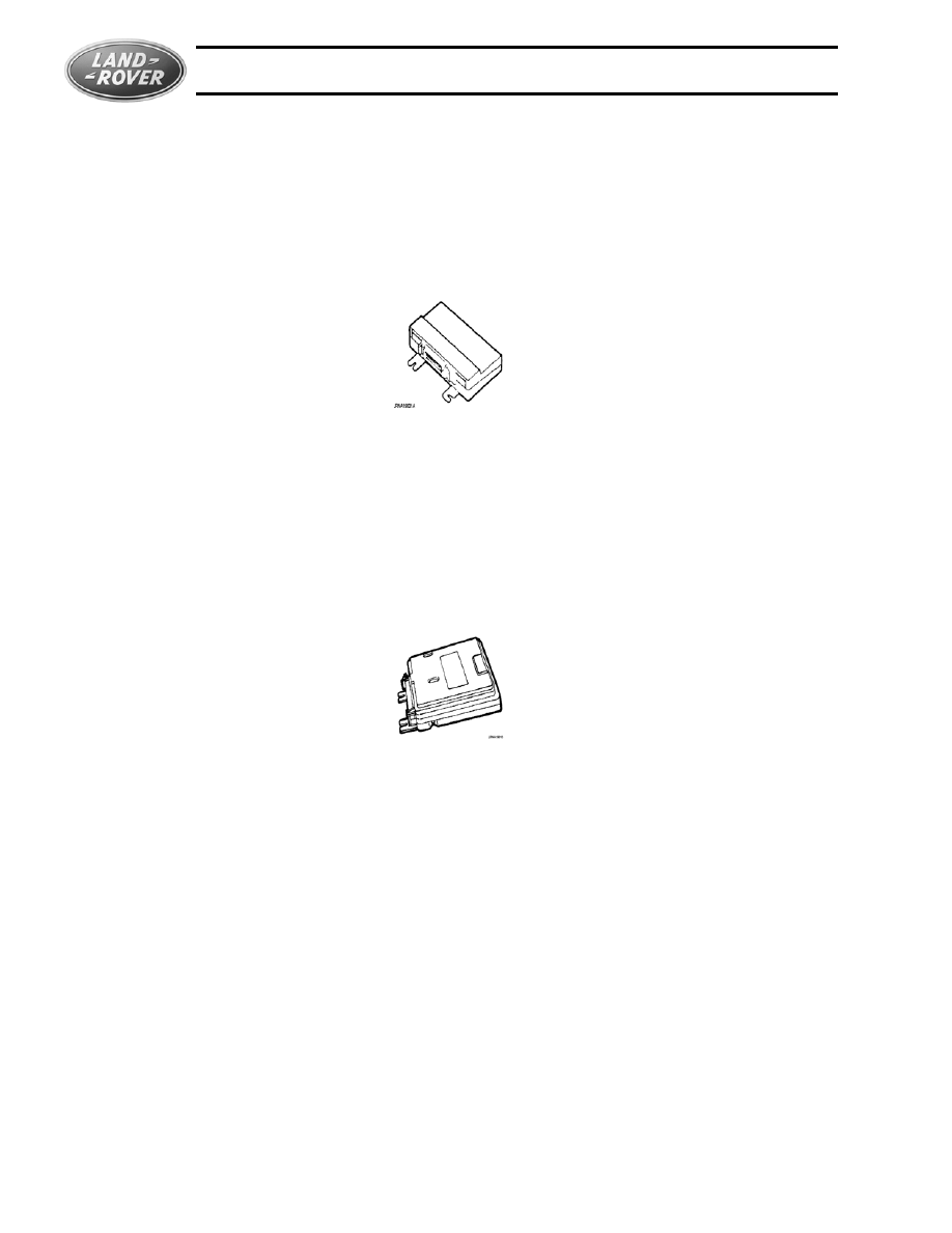
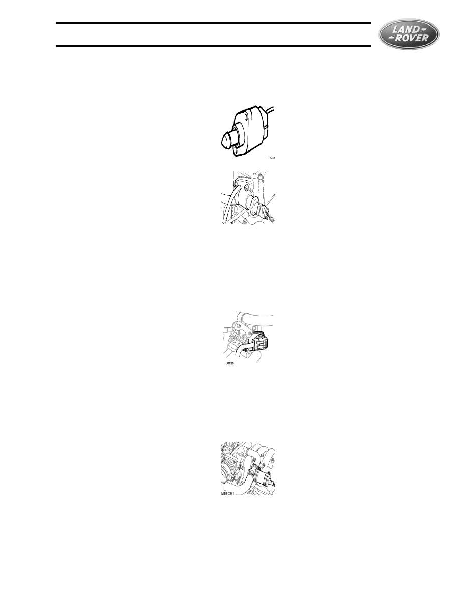
Engine Control Module (ECM)
13CU
• Used 1987 & 1988
• Limited on-board self-diagnostics
• Adaptive short term fuelling offsets for each bank
• Volatile fault memory
• Diagnostics with Land Rover/Lucas Hand-Held Tester or TestBook
• Mounted under the passenger seat
14CU/14CUX
• 14CU used 1989, 14CUX used 1990-1995
• 14CU supports adaptive TPS and ISC
• EVAP purge control
• 14CUX has extended memory & supports on-board diagnostics compliant with OBD 1
• Volatile fault memory
• Replaceable PROM chips
• Mounted under the passenger seat on 1989-1994 Range Rover Classic and 1995
Defender; Right side kick panel 1995 Range Rover Classic and Discovery; Under right side
dash 1993 Defender 110 and 1994 Defender 90.
• Diagnostics via On-board display or with Land Rover/Lucas Hand-Held Tester or TestBook
LAND ROVER FUEL INJECTION SYSTEMS
Land Rover Fuel System Components
65
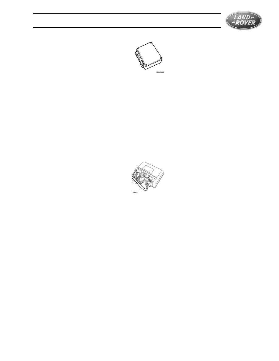
GEMS
• Used (Range Rover) 1995 to early 1999, (Discovery) 1996- early 1999, (Defender) 1997
• Both short term and long term fuelling offsets
• Ignition timing control integration
• Engine immobilization
• OBDII compliant on-board diagnostics
• Non-Volatile fault memory
• Replaceable PROM chips
• Diagnostics with SAE J1962/J1979 compatible tester or TestBook
• Mounted in engine compartment
Bosch Motronic 5.2.1
• Used 1999 - present
• Additional memory, faster processor/data bus refresh speed
• OBDII compliant on-board diagnostics and additional advanced diagnostic capability
• Both volatile and non-volatile (LEV) fault memory
• EEPROM programmable via data link
• Diagnostics with SAE J1962/J1979 compatible tester or TestBook
LAND ROVER FUEL INJECTION SYSTEMS
66
FUEL SYSTEM OUTPUTS
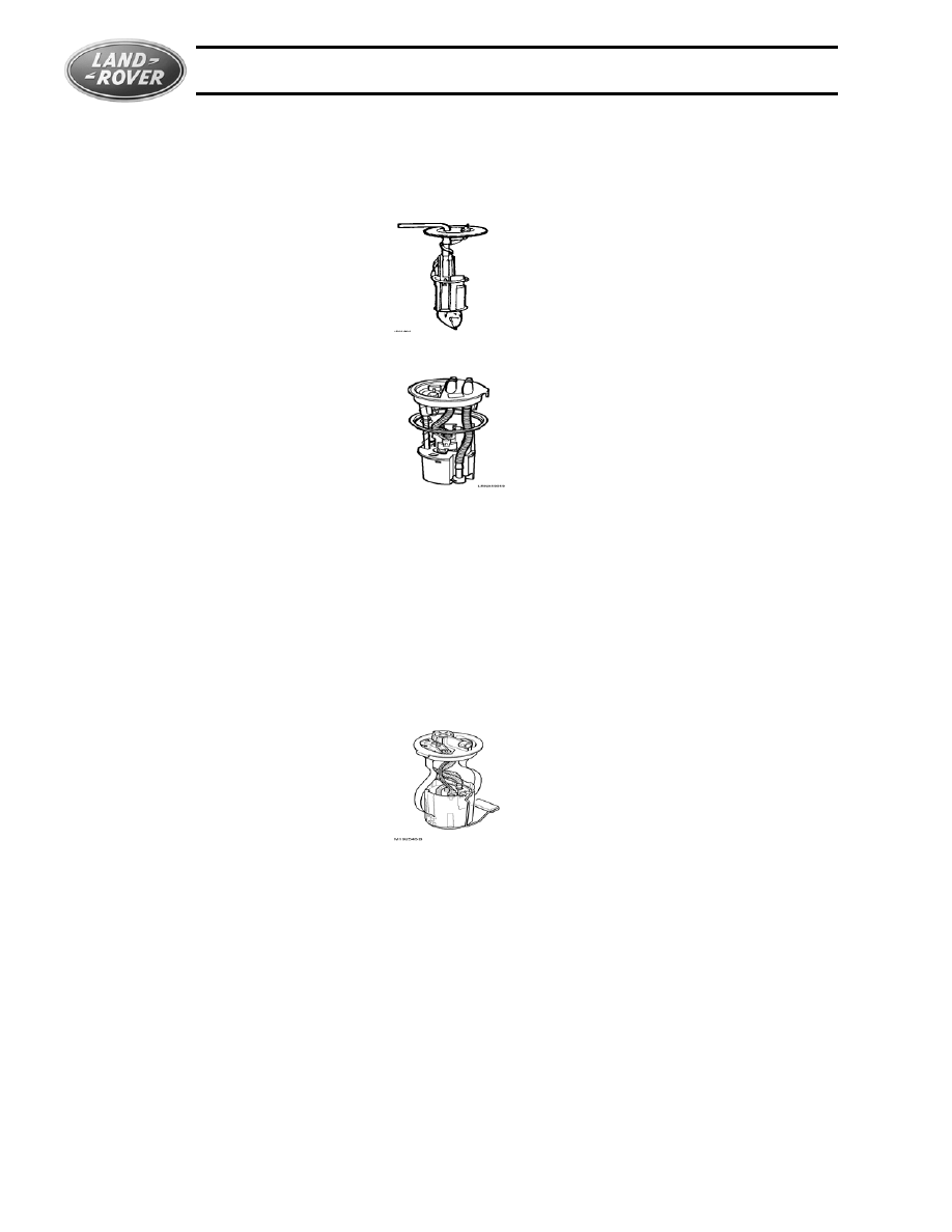
Fuel Pump
Fuel Return Type Systems -1987 to 1990
1991-1999
• Used 1987- early 1999
• Integral fuel level sending unit beginning 1991
• In-tank with external fuel filter
• 2.4-2.6 bar (34-37 psi) operating pressure
• Key off pressure drop from 2.3-2.6 bar (36-38 psi)- less
than 0.7 bar (10 psi) in one minute
• Integral Advanced EVAP sensor from October 1996
Non-Return Type System
• Used with Bosch EMS 1999- present
• Integral fuel pressure regulator
• 3.5 bar (50.75 psi) operating pressure
• Integral advanced EVAP sensor 1999-present (Except LEV Phase II vehicles)

LAND ROVER FUEL INJECTION SYSTEMS
Fuel System Outputs
67
Fuel Filter
Return Type Systems
• External 1987-1999
• Mounted on the chassis, near the passenger-side rear wheel arch. An arrow on the filter
body indicates the direction of fuel flow.
• Worm clamps 1987-1990
• O-Ring and Fitting 1991- early 1999
Non-Return Type System
• 1999- present (Bosch EMS)
• Integral with fuel pump
• Coarse gauze filter in swirl pot
• Fine paper filter around pump inlet
Fuel Pressure Regulator
Return Type Systems
• Mounted on fuel rail
• No service adjustments
• Adjusts pressure relative to intake manifold pressure
LAND ROVER FUEL INJECTION SYSTEMS
68
NON-RETURN TYPE SYSTEM
• Mounted on fuel pump
• No service adjustments
• Adjusts pressure relative to atmospheric pressure
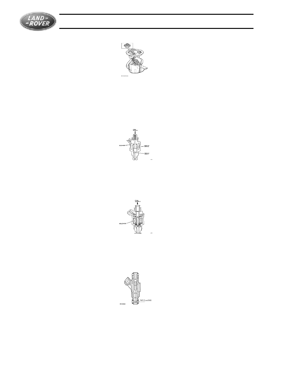
Fuel Injectors
13CU, 14CU
• Machined Needle Valve type.
• Approx. 16W resistance per injector
• Flow rate = 180-195cc (using gasoline) minimum at 2.5 bar (36 psi) at 20°C (68°F)
14CUX, GEMS
• Moveable Disc and Rod type.
• 16.2W ±0.5W resistance per injector at 20°C (68°F)
• Flow rate = 180-195cc (using gasoline) minimum at 2.5 bar (36 psi) at 20°C (68°F)
Motronic 5.2.1
• Fixed Disc and Ball-ended pintle type.
• 14.5W ±0.7W resistance per injector at 20°C (68°F)
NOTE: Injector Testing Note:The preferred method for testing all Land Rover fuel injectors is
using the procedure outlined in TIB 19/02/97/NAS. This method checks for nozzle leakage, and
also specifies that the fuel pressure drop the injectors. Each injector should be within ±13.8
LAND ROVER FUEL INJECTION SYSTEMS
Fuel System Outputs
69
kpa (2 psi) of all the other injectors when pulsed for 500ms with the test equipment.
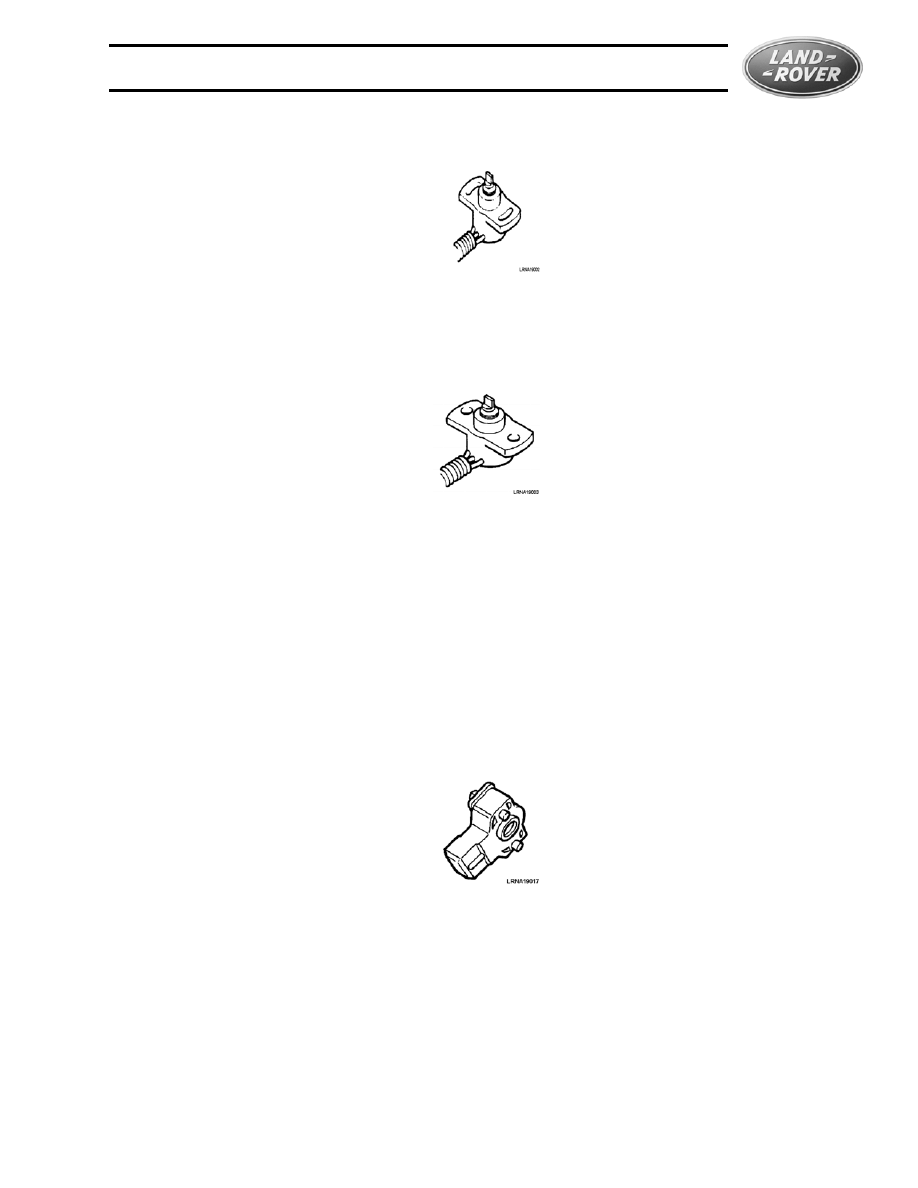
Idle Air Control Valve (IACV)
13CU, 14CU, 14CUX
• Bipolar stepper motor controlling a screw-mounted tapered valve
• Active when: Road speed less than 3 mph; Throttle closed; Engine above 50 rpm
• Air valve open = 0 steps
Air valve closed = 180 steps
• Base idle is controlled through a separate bypass port located in the housing for the throttle
butterfly.
GEMS
• Similar in operation as 13/14CU, 14CUX
• Air valve open = 200 steps (180 steps for vehicles up to 97MY)
Air valve closed = 0 steps
• Base idle is controlled through a separate bypass port located in the housing for the throttle
butterfly.
Motronic
• Pulse Width Modulated 2-winding motor, controlling a rotary valve within an idle air flow
passage
• No base idle adjustments
LAND ROVER FUEL INJECTION SYSTEMS
70
FUEL SYSTEM INPUTS
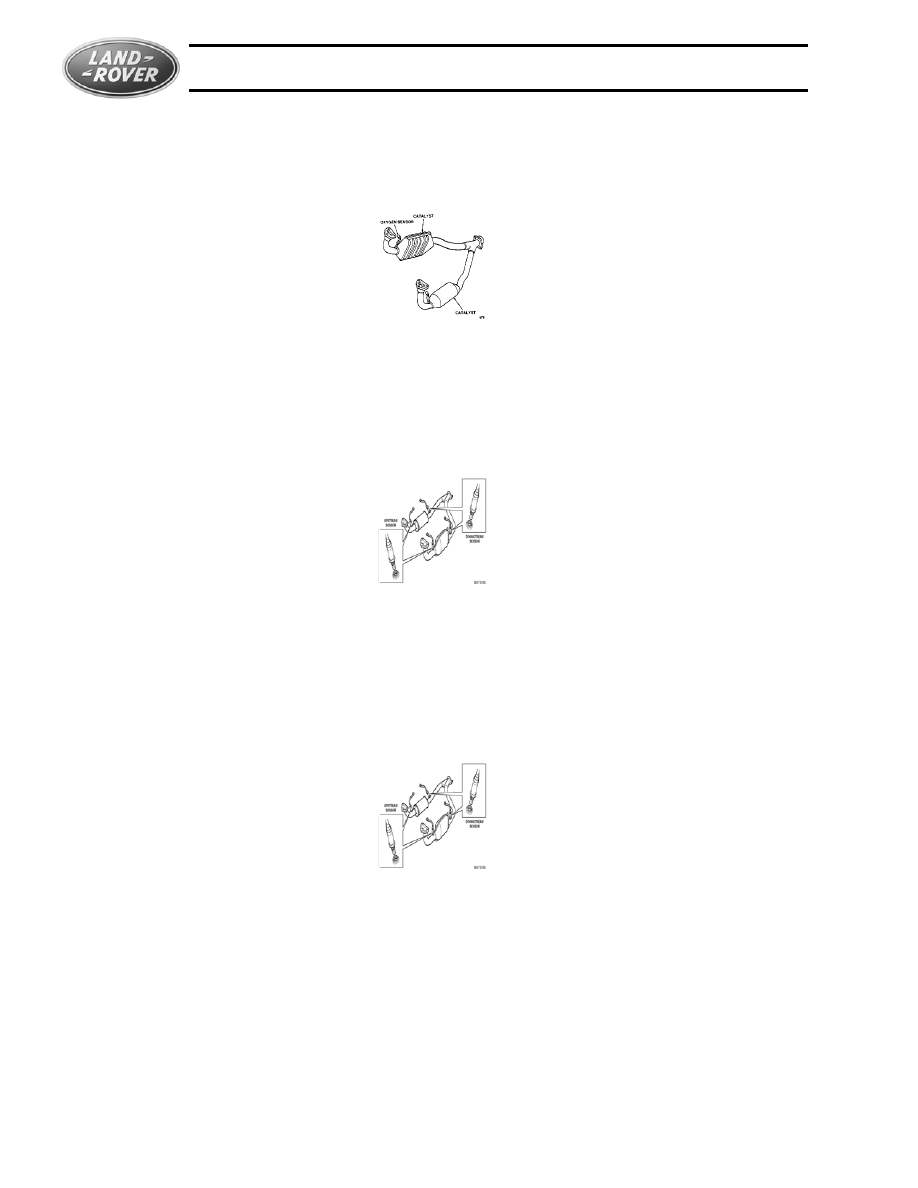
Heated Oxygen Sensor (HO2S)
13CU, 14CU,14CUX
• One heated sensor for each bank, located upstream of the catalysts
• 3-wire resistive titanium sensor element
Sensor power supplied from heater element
• Constant voltage supply to heater elements
GEMS
• Two heated sensors per bank, one pre-catalyst, one post-catalyst. Post-catalyst sensor
used only to monitor catalyst efficiency.
• 4-wire resistive titanium sensor element
5v supply from ECM
• Pulse Width Modulated voltage supply to heater elements
Motronic
• Two heated sensors per bank, one pre-catalyst, one post-catalyst. Post-catalyst sensor
used only to monitor catalyst efficiency.
• 4-wire voltage generating Zirconium sensor element
• Pulse Width Modulated voltage supply to heater elements
• Front and Rear sensors are different
LAND ROVER FUEL INJECTION SYSTEMS
Fuel System Inputs
71
Sensor Operation Notes
Resistive Sensors-
• Uses a voltage supply through the sensor element
• Resistance increases under lean conditions
Resistance decreases under rich conditions
Voltage Generating Sensors-
• Generates voltage (up to 1.1 v) under rich conditions - high voltage measured at sensor
Low or No voltage generated under lean conditions - low voltage measured at sensor
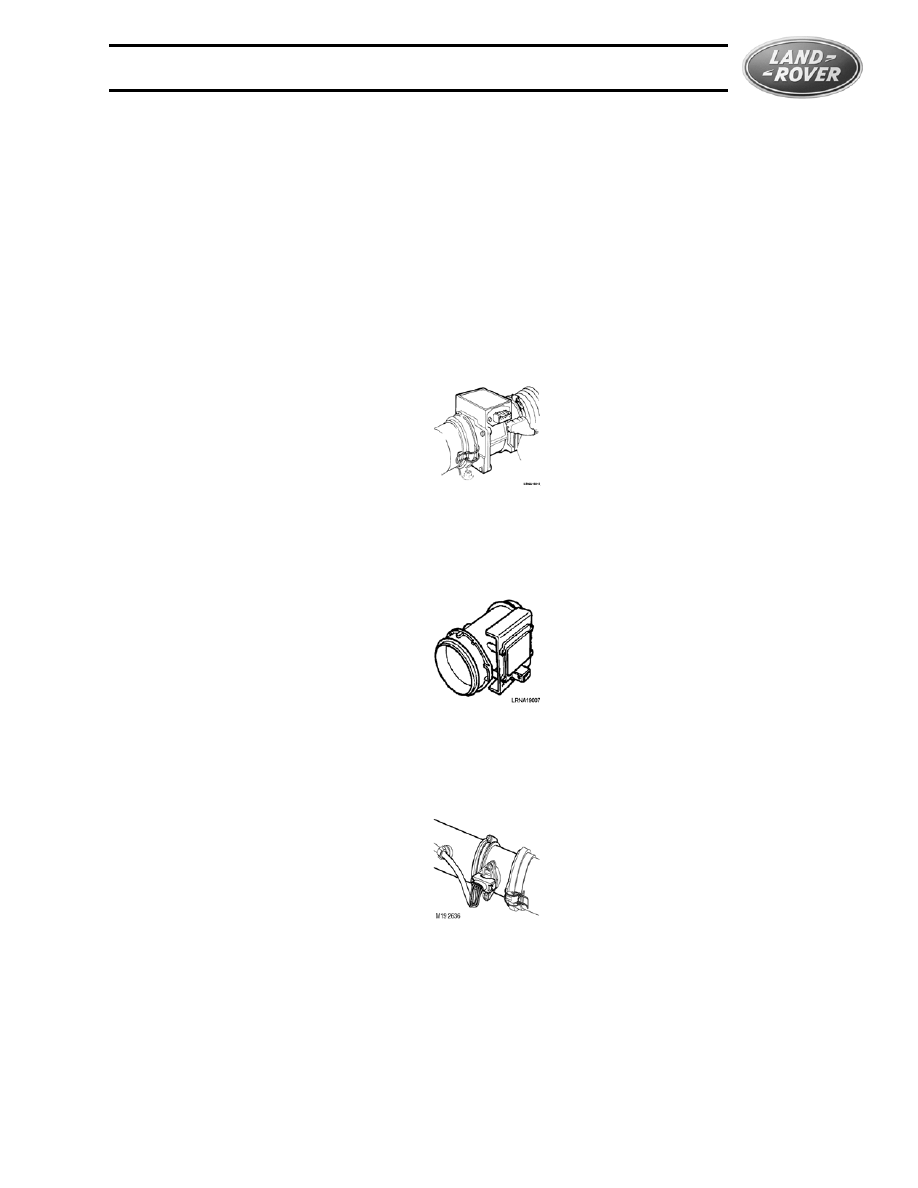
Mass Air Flow Sensor (MAFS)
13CU, 14CU, 14CUX
• Hot Wire type
• No additional intake air temperature sensor used
GEMS
• Hot Wire type
• Uses additional intake air temperature sensor
Motronic
• Hot Film type
• Uses additional intake air temperature sensor
LAND ROVER FUEL INJECTION SYSTEMS
72
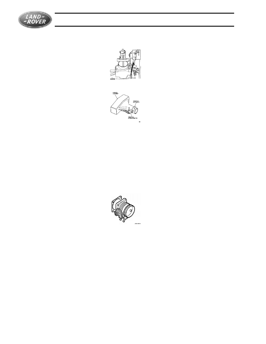
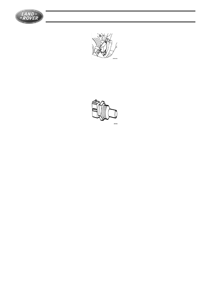
Throttle Butterfly
13CU, 14CU, 14CUX, GEMS
• Must be perpendicular within the bore
• Close tolerence between plate and bore- particular attention should be paid to deposit
build-ups
• Coolant-fed pre-heating passage underneath housing/plate area
• Cable slack is adjustable
• Linkage and stop screw wear may allow plate to ‘flip backwards’ slightly in bore
• Adjustment must be made using a depth gauge
• 1987 Models have adjustment screw mounted on throttle lever, all others have screw
mounted in housing as shown
Motronic
• No plate adjustment normally needed
• Cable slack is adjustable
• Coolant-fed pre-heating passage underneath housing/plate area
LAND ROVER FUEL INJECTION SYSTEMS
Fuel System Inputs
73
Throttle Position Sensor (TPS)
13CU
• Adjustable- ECM DOES NOT adapt
• Voltage Range 0.29-0.36v throttle closed
4.2-4.8v throttle open
14CU
• Non-Adjustable- ECM is adaptive
• Voltage Range 0.085-0.545v throttle closed
4.2-4.9v throttle open
14CUX
• Non-Adjustable- ECM is adaptive
• Voltage Range 0.083-0.547v throttle closed
4.7-4.9v throttle open
GEMS
• Non-Adjustable- ECM is adaptive
• Voltage Range approx. 0.6v throttle closed
approx. 4.5v throttle open
LAND ROVER FUEL INJECTION SYSTEMS
74
Motronic
• Non-Adjustable- ECM is adaptive
• Voltage Range 0.29-0.36v throttle closed
4.2-4.9v throttle open
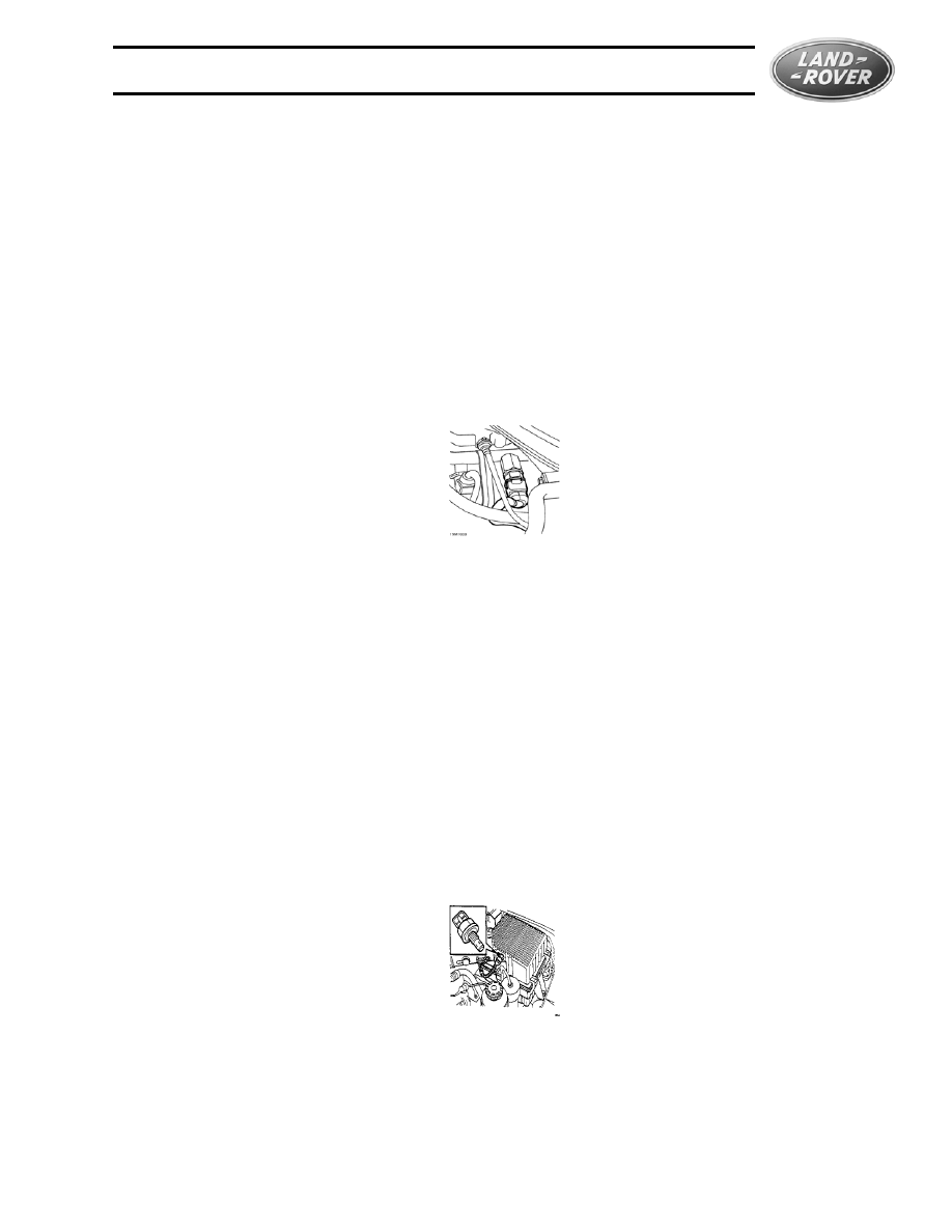
Engine Coolant Temperature Sensor (ECT)
13CU/14CU/14CUX
• NTC type sensor
• Resistance range = approx. 9200W at -10°C (-22°F) to 175W at 100°C (212°F). Approx.
300W at 80°C (176°F).
• ECM fault default value = 36°C (96.8°F).
• Located at the top front of the engine, to the right of the alternator and in front of the plenum
chamber.
GEMS
• NTC type sensor
• Output = Approx. 4.7v at -30°C (-22°F) to 0.25v at 130°C (302°F). Approx. 0.7v at 85°C
(185°F)
• ECM fault default value = dependant on value of air temperature sensor
• Located at the top front of the engine, to the right of the alternator and in front of the plenum
chamber.
Motronic
• NTC type sensor
• Sensor contains two elements, only one is used on Discovery, on Range Rover one is also
used for the instrument temperature gauge.
• Output = Approx. 4.9v at -50°C (-58°F) to 0.75v at 130°C (266°F). Approx. 1.8v at 70°C
(158°F)
• ECM fault default value = dependant on software map up to 60°C (140°F), after which
LAND ROVER FUEL INJECTION SYSTEMS
Fuel System Inputs
75
defaults to 85°C (185°F)
• Located at the top front of the engine, to the right of the alternator and in front of the plenum
chamber.
Engine Fuel Temperature Sensor (EFT)
13CU/14CU/14CUX
• NTC type sensor
• Range = 9.1k-W at -10 °C (14°F) to 150W at 100°C (212°F). Approx. 1.2 k-W at 40°C
(104°F)
• Located on the fuel rail forward of the intake housing, between left and right injector banks
GEMS
• NTC type sensor
• Range = 23k-W at -30 °C (-22°F) to 290W at 80°C (176°F). Approx. 1.1 k-W at 40°C
(104°F)
• Located on the fuel rail by cylinders 3 and 5
Motronic
• None used
Intake Air Temperature Sensor (IAT)
13CU/14CU/14CUX
• None used
GEMS
• NTC type sensor
• Retards ignition timing above 55°C (131°F)
• Range = 23k-W at -30 °C (-22°F) to 290W at 80°C (176°F)
• Located in air cleaner housing
LAND ROVER FUEL INJECTION SYSTEMS
76
Motronic
• NTC type sensor
• Range = 4.75v at -40 °C (-40°F) to .25v at 130°C (266°F)
• Default fault value = 45°C (113°F)
• Integral with Mass Air Flow Sensor
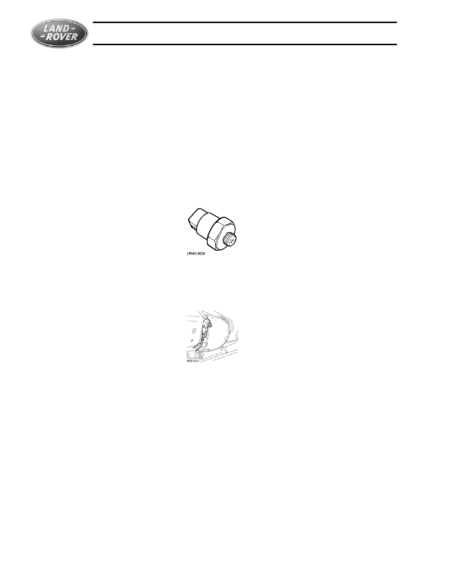
Knock Sensor
13CU/14CU/14CUX
• None used
GEMS
• Two used- mounted on the cylinder block between the two center cylinders of each bank
• Voltage output increases with severity of knock detected
Motronic
• Same location and operation as GEMS

LAND ROVER FUEL INJECTION SYSTEMS
Open and Closed Loop Operation
77
OPEN AND CLOSED LOOP OPERATION
CLOSED LOOP OPERATION
During closed loop, or feedback operation, the ECM controls fuel system operation based on
information provided by the various vehicle inputs. Because these inputs represent actual
operating conditions, the system is most able to meet performance and efficiency targets when
operating in closed loop.
The primary input during closed loop operation is the oxygen sensor since it indicates the result
of the combustion process, regardless of the engine speed and load.
The primary output during closed loop operation is the fuel injector timing and duration.
All other sensors generally serve to help the ECM ‘trim’ or anticipate the operation of the engine
to meet a particular oxygen sensor value or known tailpipe emission condition.
OPEN LOOP OPERATION
At times (start-up, full throttle) engine operating requirements may fall outside the bounds of
that suggested by the ECM inputs. Some sensors do not operate at peak efficiently until warm.
At these times, the ECM substitutes a pre-programmed set of reference inputs that are most
likely to produce desired engine operation. This is referred to as open loop operation.
The system may also default to open loop operation when component failure provides an input
signal outside the range of known parameters recognized by the ECM. The ECM will substitute
a signal value that allows the vehicle to continue to operate. The Malfunction Indicator Lamp
(CHECK ENGINE) on the instrument panel is illuminated at this time to indicate the failure of an
emissions-related component.

LAND ROVER FUEL INJECTION SYSTEMS
78
Document Outline
- Introduction
- Engine Control Module
- FUEL SYSTEM OUTPUTS
- FUEL SYSTEM INPUTS
- OPEN AND CLOSED LOOP OPERATION
Wyszukiwarka
Podobne podstrony:
Fuel injection ASZ
Gasoline Fuel Injection System K Jetronic
Fuel Injection Systems Bosch Cis
Mechanics of a Diesel Fuel Injection System
SMeyer CA2067735A1 Water Fuel Injection System
How to configure fuel injectors on the pre CAN Duratorq HPCR
Self Study Programme 351 Common rail fuel injection system fitted in the 3 0l V6 TDI engine
Bosch K Jetronic And Ke Jetronic Mechanical Fuel Injection Haynes
Fuel injection
Bmw e12 5 Series L Jetronic Fuel Injection Systems
Audi A8 4,2 fuel injection engine ENG
BOSCH HDI EDC15C2 injection system (2)
biogas as vehicle fuel id 87120 Nieznany
4 Fuel and Lubrication System
08 fuel system
05 Fuel System
więcej podobnych podstron