Service
5
Service Department. Technical Information
Printed in Czech Republic
S00.5328.00.20
Workshop Manual
FABIA 2000
➤
1.9/96 TDI Engine, Fuel Injection
Edition 07.03
Engine code
ASZ

Service
5
The Workshop Manual is intended only for use within the Organisation Škoda.
It is not permitted to pass it on to other persons.
© ŠKODA AUTO a. s.
Printed in Czech Republic
S00.5328.00.20
FABIA 2000
➤
1.9/96 TDI Engine, Fuel Injection
List of Supplements
Edition 09.04
S00.5328.01.20
List of Supplements to Workshop Manual
FABIA 2000
➤
1.9/96 TDI Engine, Fuel Injection
Edition 07.03
Supple-
ment
Edition
Subject
Article Number
07.03
Basic Edition
S00.5328.00.20
1
09.04
Modifications in Rep. Gr. 01 and 23
S00.5328.01.20

FABIA 2000
➤
1.9/96 TDI Engine, Fuel Injection
List of Supplements
Edition 09.04
S00.5328.01.20

FABIA 2000
➤
1.9/96 TDI Engine, Fuel Injection
Table of Contents
Edition 09.04
S00.5328.01.20
I
Table of Contents
01 – Self-diagnosis
Self-diagnosis I ........... ............... .............. ............... ............... .............. .....
- Properties of the self-diagnosis ...... .............. ............... ............... .............. .....
- Technical data of self-diagnosis ...... .............. ............... ............... .............. .....
- Connecting vehicle system tester -V.A.G 1552- and selecting the control unit for engine
electronics . ............... ............... .............. ............... ............... .............. .....
- Interrogating and erasing fault memory ........... ............... ............... .............. .....
- Actuator diagnosis ....... ............... .............. ............... ............... .............. .....
Self-diagnosis II ........... ............... .............. ............... ............... .............. .....
- Fault codes 16485 to 19561 .......... .............. ............... ............... .............. .....
Self-diagnosis III .......... ............... .............. ............... ............... .............. .....
- Readiness code .......... ............... .............. ............... ............... .............. .....
- Reading readiness code ............... .............. ............... ............... .............. .....
- Generating readiness code ........... .............. ............... ............... .............. .....
Self-diagnosis IV ......... ............... .............. ............... ............... .............. .....
- Reading measured value block ...... .............. ............... ............... .............. .....
- Display groups 001 to 022, engine idling ......... ............... ............... .............. .....
- Display groups 004 through 011 at full load ...... ............... ............... .............. .....
- Display group 125 - CAN databus ... .............. ............... ............... .............. .....
23 – Fuel Formation, Injection
Diesel Direct Injection System ....... .............. ............... ............... .............. .....
- Safety measures ......... ............... .............. ............... ............... .............. .....
- Rules of cleanliness ..... ............... .............. ............... ............... .............. .....
- Overview of fitting locations ........... .............. ............... ............... .............. .....
- Disassembling and assembling intake manifold . ............... ............... .............. .....
- Removing and installing air filter ..... .............. ............... ............... .............. .....
- Disassembling and assembling the air filter ...... ............... ............... .............. .....
Disassembling and assembling the unit injector ............. ............... .............. .....
Testing components ..... ............... .............. ............... ............... .............. .....
Testing exhaust gas recirculation ... .............. ............... ............... .............. .....
- Connection diagram of vacuum hoses for exhaust gas recirculation ....... .............. .....
- Testing exhaust gas recirculation .... .............. ............... ............... .............. .....
Engine control unit ....... ............... .............. ............... ............... .............. .....
- Testing voltage supply for engine control unit ... ............... ............... .............. .....
- Replacing diesel direct injection system control unit -J248- . ............... .............. .....
- Coding diesel direct injection system control unit -J248- ..... ............... .............. .....
- Activating and deactivating cruise control system (CCS) ..... ............... .............. .....
Testing auxiliary signals ............... .............. ............... ............... .............. .....
28 – Glow Plug System
Testing preheating system ............ .............. ............... ............... .............. .....
01-1
page
1
01-1
page
1
01-1
page
1
01-1
page
2
01-1
page
3
01-1
page
5
01-2
page
1
01-2
page
1
01-3
page
1
01-3
page
1
01-3
page
1
01-3
page
2
01-4
page
1
01-4
page
1
01-4
page
1
01-4
page
9
01-4
page 11
23-1
page
1
23-1
page
1
23-1
page
1
23-1
page
2
23-1
page
5
23-1
page
5
23-1
page
6
23-2
page
1
23-3
page
1
23-4
page
1
23-4
page
1
23-4
page
1
23-5
page
1
23-5
page
1
23-5
page
2
23-5
page
3
23-5
page
4
23-6
page
1
28-1
page
1

FABIA 2000
➤
1.9/96 TDI Engine, Fuel Injection
Table of Contents
Edition 09.04
S00.5328.01.20
II
FABIA 2000
➤
1.9/96 TDI Engine, Fuel Injection
Self-diagnosis I
Edition 07.03
S00.5328.00.20
01-1
page
1
01
01-1
Self-diagnosis I
Properties of the self-diagnosis
The control unit for the diesel direct injection system is
equipped with a fault memory. The fault memory is de-
signed as a permanent memory.
If malfunctions occur in the monitored sensors or compo-
nents, they are stored in the fault memory with indication
of the fault type. Fault table
⇒
Chap. 01-2.
Faults which occur only temporarily (sporadically) are
displayed with the suffix „/SP“. Possible causes of spo-
radic faults are e.g. a loose contact or a temporary line in-
terruption. If a sporadic fault no longer occurs after 50
engine starts, it is automatically erased.
If faults are detected that are likely to influence the driving
behaviour, the glow period warning lamp -K29- flashes.
The stored faults can be read out with the vehicle system
tester -V.A.G 1552-, -V.A.G 1551- or -VAS 5051-
⇒ 01-1
page 2.
After the fault(s) has(have) been removed the fault mem-
ory must be erased
⇒ 01-1
page 3.
The following description only relates to vehicle system
tester -V.A.G 1552- using the current program card.
When not using the current program card or when using
the fault read-out scan tool -V.A.G 1551- with integrated
printer or using the vehicle diagnosis, measurement and
information system -VAS 5051- a minor deviation in the
display is possible.
Technical data of self-diagnosis
Interrogating control unit version
The control unit version is displayed once the vehicle sys-
tem tester -V.A.G 1552 - is connected and the engine
electronics control unit is selected
⇒ 01-1
page 2.
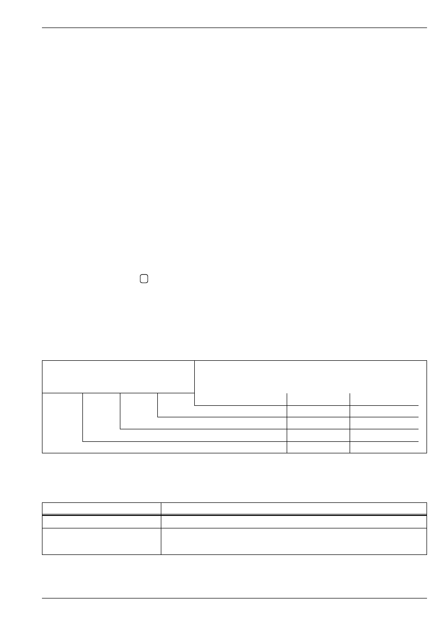
Available functions when using the vehicle sys-
tem tester -V.A.G 1552-
The conditions under which the desired functions can be
selected are given in the following table.
01 – Self-diagnosis
Note
FABIA 2000
➤
1.9/96 TDI Engine, Fuel Injection
Self-diagnosis I
Edition 07.03
S00.5328.00.20
01-1
page
2
01
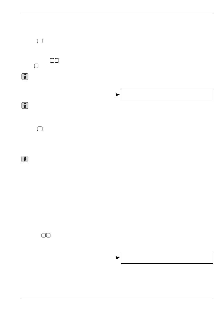
Connecting vehicle system tester
-V.A.G 1552- and selecting the control
unit for engine electronics
Special tools, test and measuring equipment and
auxiliary items required
♦
Vehicle system tester -V.A.G 1552- with cable
-V.A.G 1551/3, 3A, 3B oder 3C-
Test conditions
•
Battery voltage at least 11.5 volts
•
Earth connection to engine and gearbox O.K.
•
Fuses according to current flow diagram O.K.
Procedure
–
Connect vehicle system tester -V.A.G 1552- with ap-
propriate cable.
Once the vehicle system tester has been connected:
–
Switch on the ignition or start
⇒ 01-1
page 1 engine
depending on the function desired.
♦
If „data transfer errors“ are displayed as a result of an
incorrect entry, disconnect cable at vehicle system
tester, connect it in again and repeat all the steps.
♦
If one of the following messages appears in the dis-
play, test the diagnostic cable
⇒
Current Flow Dia-
grams, Electrical Fault Finding and Fitting Locations
or
⇒
Operating Instructions of vehicle system tester.
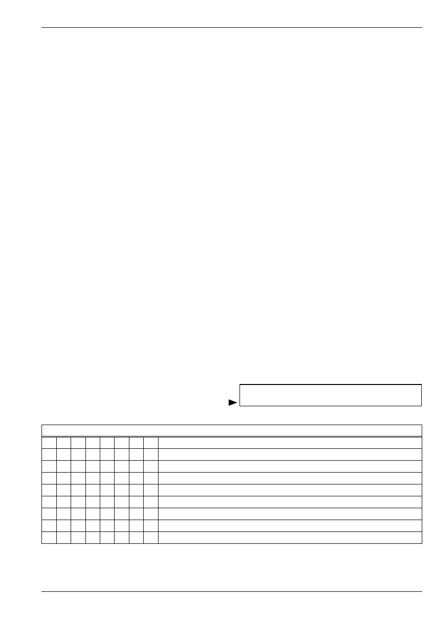
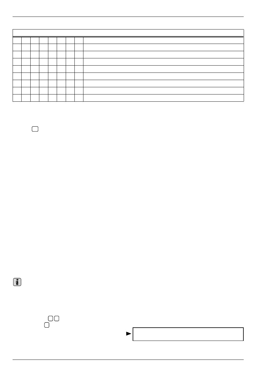
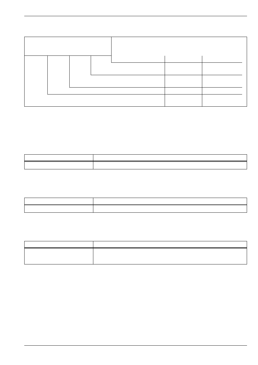
Operation
Precondition
Engine not running,
ignition switched on
Engine idling
Normal driving
01
Interrogating control unit
version
yes
yes
yes
02
Interrogating fault mem-
ory
yes
1)
1)
Only perform with the ignition on, if the engine does not start.
yes
yes
03
Actuator diagnosis
yes
yes
no
04
Basic setting
no
yes
no
05
Erasing fault memory
yes
yes
yes
06
Ending output
yes
yes
yes
07
Coding control unit
yes
no
no
08
Reading measured val-
ue block
yes
yes
yes
11
Login procedure
yes
no
no
V.A.G 1551/3
1552
V.A.G.
HELP
Q
O
C
9
8
7
6
5
4
3
2
1
V.A.G 1552
S01-0045
Note
Vehicle system test HELP
The control unit does not respond
FABIA 2000
➤
1.9/96 TDI Engine, Fuel Injection
Self-diagnosis I
Edition 07.03
S00.5328.00.20
01-1
page
3
01
–
Operate the vehicle system tester by referring to the
read-out on the display.
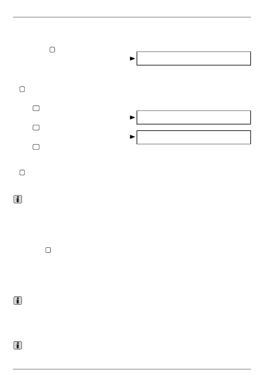
Readout on display:
–
Enter address word 01 „Engine electronics“ and con-
firm entry with
.
The control unit identification appears in the display, e.g.:
♦
038906019LA = Part No. of the control unit (for current
control unit version see spare parts catalogue)
♦
1.9 ltr. = engine displacement
♦
R4 = engine version (4 cyl. in-line engine)
♦
EDC = Injection system (Electronic Diesel Control)
♦
CC = Cruise control system activated (only on models
with CCS)
♦
000 = Control unit ID
♦
MG = Manual gearbox
♦
1576 = Data status (Software version of the control
unit)
♦
Coding 00102 = Coding variant of the control unit
♦
WSC XXXXX = Workshop code
♦
If the control unit version displayed does not corre-
spond to the vehicle, replace the control unit
⇒
Chapter 23-5.
♦
Incorrect coding of the engine control unit results in:
♦
Handling problems (jerky gear change, load change
jolts etc.)
♦
Increase in fuel consumption
♦
Increase in pollution
♦
Storage of non-existent faults in fault memory
Interrogating and erasing fault memory
Special tools, test and measuring equipment and
auxiliary items required
♦
Vehicle system tester -V.A.G 1552- with cable
-V.A.G 1551/3, 3A, 3B oder 3C-
Interrogating fault memory
–
Connect vehicle system tester -V.A.G 1552-. Start en-
gine and select address word 01 „Engine electronics“
⇒ 01-1
page 2.
Vehicle system test HELP
Fault in communication set-up
Vehicle system test HELP
K cable does not connect to earth
Vehicle system test HELP
K cable doest not connect to pos. term.
Vehicle system test HELP
Enter address word XX
Q
038906019LA 1.9l R4 EDC G000SG 1576 ->
Coding 00102 WSC XXXXX
Note
FABIA 2000
➤
1.9/96 TDI Engine, Fuel Injection
Self-diagnosis I
Edition 07.03
S00.5328.00.20
01-1
page
4
01
Only if the engine does not start:
–
Switch on ignition.
–
Enter function 02 „Interrogate fault memory“ and con-
firm entry with
.
The number of stored faults or „No fault recognised“ ap-
pears in the display.
If no fault is stored:
–
Enter function 06 „End output“ and confirm entry with
.
If one or several faults are stored:
–
Press .
Readout on display, e.g.:
–
Press .
Fault source and fault type appear in the display, e.g.:
–
Press .
The stored faults are displayed in sequence.
–
Enter function 06 „End output“ and confirm entry with
.
–
Rectify the faults displayed by referring to the fault ta-
ble
⇒
Chapter 01-2.
When carrying out testing and removal and installation
operations faults such as connector unplugged or CAN
bus faults, may also be detected by other control units.
This is why, when the work is concluded, that it is neces-
sary to interrogate and erase the fault memory on all con-
trol units. For this you must proceed as follows:
–
Enter function 00 for „Automatic test sequence“ and
confirm with
.
The Vehicle system tester -V.A.G 1552- sends all the
known address words one after the other.
Erasing fault memory
Test conditions
Whenever the fault memory is erased, it is necessary to
generate a readiness code
⇒
Chap. 01-3.
•
Fault eliminated
•
Fault memory interrogated
⇒ 01-1
page 3
After fault elimination the fault memory must again be in-
terrogated and subsequently erased.
Q
X faults detected!
Q
->
Fault number: 16685 P0301 044....
Cylinder 1 ->
Combustion misfiring detected
Q
Note
Q
Note
Note
FABIA 2000
➤
1.9/96 TDI Engine, Fuel Injection
Self-diagnosis I
Edition 07.03
S00.5328.00.20
01-1
page
5
01
–
Enter function 05 „Erase fault memory“ and confirm
with .
Readout on display:
If the ignition is switched off during „Interrogating fault
memory“ and „Erasing fault memory“, the fault memory is
not erased.
–
Select function 06 „End output“ and confirm with
.
–
Perform a test drive. Then, again interrogate the fault
memory. No fault must be displayed.
Actuator diagnosis
With the actuator diagnosis the following parts are acti-
vated in the sequence indicated:
1 - Exhaust gas recirculation solenoid valve -N18-
2 - AC compressor engagement
3 - Solenoid valve for charge pressure control
-N75-
4 - Change-over valve for intake manifold flap
-N239-
5 - Glow period warning lamp -K29-
6 - Radiator fan control
7 - Glow plug relay -J52-
8 - Low heat output relay -J359-
9 - High heat output relay -J360-
10 - Fault lamp
♦
Actuation of the individual control elements is limited
to 30 seconds.
♦
If the actuator diagnosis must be repeated without the
engine being started in the meantime, switch off igni-
tion for about 20 seconds.
Special tools, test and measuring equipment and
auxiliary items required
♦
Vehicle system tester -V.A.G 1552- with cable
-V.A.G 1551/3, 3A, 3B oder 3C-
Test conditions
•
Fuses according to current flow diagram O.K.
Procedure
–
Connect vehicle system tester -V.A.G 1552-. Start en-
gine and select address word 01 „Engine electronics“
⇒ 01-1
page 2.
Q
Vehicle system test ->
Fault memory was erased
Note
Q
Note
FABIA 2000
➤
1.9/96 TDI Engine, Fuel Injection
Self-diagnosis I
Edition 07.03
S00.5328.00.20
01-1
page
6
01
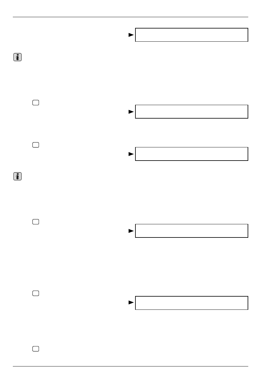
–
Enter function 03 „Final control diagnosis“.
Readout on display:
The valve must click.
The clicking of the valve cannot be heard because of the
engine noise and can therefore only be checked.
If the valve does not click:
–
Testing Exhaust gas recirculation valve -N18-
⇒
Chap. 23-1.
–
Press .
Readout on display:
This test step is also activated on vehicles without AC
system.
Disregard display.
–
Press .
Readout on display:
The valve must click.
The clicking of the valve cannot be heard because of the
engine noise and can therefore only be checked.
If the valve does not click:
–
Test charge pressure control solenoid valve -N75-
⇒
Chap. 23-1.
–
Press .
Readout on display:
The engine must stop.
If the engine does not stop:
–
Switch off ignition.
–
Inspecting Intake manifold flap change-over valve
-N239-
⇒
Chap. 23-1.
–
Continue final control diagnosis with the engine off
and the ignition switched on.
–
Press .
Readout on display:
The warning light for glow period must flash.
If the warning light for glow period does not flash:
–
Testing Glow period warning lamp - K29-
⇒
Current
Flow Diagrams, Fault Finding Electrics and Fitting Lo-
cations.
–
Press .
Actuator diagnosis ->
Exhaust gas recirculation valve -N18
Note
Actuator diagnosis ->
AC compressor engagement
Actuator diagnosis ->
Charge press.control solenoid valve -N75
Note
Actuator diagnosis ->
Intake manif.flap change-over valve-N239
Actuator diagnosis ->
Glow period warning lamp -K29
FABIA 2000
➤
1.9/96 TDI Engine, Fuel Injection
Self-diagnosis I
Edition 07.03
S00.5328.00.20
01-1
page
7
01
Readout on display:
Radiator fan must start running at 30 second intervals
and stop.
If the fan does not run:
–
Testing radiator fan and radiator fan control unit
-J293-
⇒
Current Flow Diagrams, Fault Finding
Electrics and Fitting Locations.
–
Press .
Readout on display:
The relay must click.
It is also possible to observe the relay switching on and
off by the interior light becoming brighter or darker
(caused by the high power consumption of glow plugs).
If the relay does not click:
–
Test glow plug relay -J52-
⇒
Current Flow Diagrams,
Electrical Fault Finding and Fitting Locations.
–
Press .
Readout on display:
The relay must click.
If the relay does not click:
–
Test low heat output relay -J359-
⇒
Current Flow Di-
agrams, Electrical Fault Finding and Fitting Locations.
–
Press .
Readout on display:
The relay must click.
If the relay does not click:
–
Test high heat output relay -J360-
⇒
Current Flow Di-
agrams, Electrical Fault Finding and Fitting Locations.
–
Press .
Readout on display:
The fault lamp must flash.
If the fault lamp does not flash:
–
Test fault lamp
⇒
Current Flow Diagrams, Electrical
Fault Finding and Fitting Locations.
–
Press .
Readout on display:
–
Select function 06 „End output“ and confirm with
.
Actuator diagnosis ->
Radiator fan control
Actuator diagnosis ->
Glow plug relay -J52
Actuator diagnosis ->
Low heat output relay -J359
Actuator diagnosis ->
High heat output relay -J360
Actuator diagnosis ->
Fault lamp
Vehicle system test HELP
Select function XX
Q

FABIA 2000
➤
1.9/96 TDI Engine, Fuel Injection
Self-diagnosis I
Edition 07.03
S00.5328.00.20
01-1
page
8
01
FABIA 2000
➤
1.9/96 TDI Engine, Fuel Injection
Self-diagnosis II
Edition 07.03
S00.5328.00.20
01-2
page
1
01
01-2
Self-diagnosis II
Fault codes 16485 to 19561
♦
The fault table is ordered according to the 5-digit fault code on the left.
♦
The SAE code which is displayed on the right next to the fault code (e.g.. P0107) can be ignored (at present only
valid for USA).
♦
Explanations regarding fault types (e.g. „open circuit or short-circuit to earth“)
⇒
Operating instructions for the ve-
hicle system tester.
♦
If parts are output as faulty: First of all test all leads and plug connections to these components, as well as the earth
connections according to current flow diagram. Replace component only if these tests do not reveal any fault. This
applies in particular if the fault is shown as „sporadic“ (SP).
♦
If the vehicle system tester -V.A.G 1552 - displays „Information in the documentation“; look up the relevant text in
the fault table according to the fault code indicated.
Readout on -V.A.G 1552-
Rectifying fault
16485
Air mass meter -G70
Implausible sig-
nal
–
Test air mass meter -G70-
⇒
Chap. 01-4, display group 003
16684
Combustion misfiring
detected
–
Inspecting compression pressure
⇒
1.9/96 TDI Engine, Mechanics;
Rep. Gr. 15
–
Check unit injector
⇒
Chap. 23-3
16685
Cyl. 1 combustion mis-
firings detected
16686
Cyl. 2 combustion mis-
firings detected
16687
Cyl. 3 combustion mis-
firings detected
16688
Cyl. 4 combustion mis-
firings detected
16705
Engine speed sender -
G28
Implausible sig-
nal
–
Inspecting Engine speed sender -G28-
⇒
Chap. 23-1
16706
Engine speed sender -
G28
No signal
–
Inspecting Engine speed sender -G28-
⇒
Chap. 23-1
–
Check wiring according to current flow diagram
⇒
Current Flow Dia-
grams, Electrical Fault Finding and Fitting Locations
–
Replace diesel direct injection system control unit -J248-
⇒
Chap.
23-5
16725
Camshaft pos. sensor
=> Sender -G40
Implausible sig-
nal
–
Test camshaft position sensor -G40-
⇒
Current Flow Diagrams,
Electrical Fault Finding and Fitting Locations
–
Remove open circuit in wiring or short circuit according to current
flow diagram
⇒
Current Flow Diagrams, Electrical Fault Finding and
Fitting Locations
–
Inspect position of camshaft and rotor
⇒
1.9/96 TDI Engine, Me-
chanics; Rep. Gr. 15
16885
Vehicle speed signal
Implausible sig-
nal
–
Test vehicle speed signal
⇒
Chapter 23-6
Note
FABIA 2000
➤
1.9/96 TDI Engine, Fuel Injection
Self-diagnosis II
Edition 07.03
S00.5328.00.20
01-2
page
2
01
16944
Voltage supply
Implausible sig-
nal
–
Test cables to diesel direct injection system control unit - J248- ac-
cording to the current flow diagram
⇒
Current Flow Diagrams, Elec-
trical Fault Finding and Fitting Locations
16946
Voltage supply
Voltage too low
16947
Voltage supply
Voltage too high
16955
Brake light switch -F
Implausible sig-
nal
–
Test brake light switch -F- and Brake pedal switch -F47-
⇒
Chap.
01-4, display group 006
16989
Control unit defective
–
Replace diesel direct injection system control unit -J248-
⇒
Chap.
23-5
17552
Air mass meter -G70
Open circuit or
short circuit to
earth
–
Test air mass meter -G70-
⇒
Chap. 01-4, display group 003
–
Check wiring according to current flow diagram
⇒
Current Flow Dia-
grams, Electrical Fault Finding and Fitting Locations
–
Replace diesel direct injection system control unit -J248-
⇒
Chap.
23-5
17553
Air mass meter -G70
Short circuit to
positive
17554
Air mass meter -G70
Supply voltage
17563
Intake manifold pres-
sure sender -G71
Short circuit to
positive
–
Test intake manifold pressure sender -G71-
⇒
Current Flow Dia-
grams, Electrical Fault Finding and Fitting Locations
–
Check wiring according to current flow diagram
⇒
Current Flow Dia-
grams, Electrical Fault Finding and Fitting Locations
–
Replace diesel direct injection system control unit - J248-
⇒
Chap.
23-5
–
Test charge pressure
⇒
Chap. 01-4, display groups 000 and 010
17564
Intake manifold pres-
sure sender -G71
Open circuit or
short circuit to
earth
17565
Intake manifold pres-
sure sender -G71
Supply voltage
17568
Intake manifold temp.
sender -G72
Short circuit to
earth
–
Test intake manifold temperature sender -G72-
⇒
Chap. 01-4, dis-
play group 007
–
Check wiring according to current flow diagram
⇒
Current Flow Dia-
grams, Electrical Fault Finding and Fitting Locations
–
Replace diesel direct injection system control unit -J248-
⇒
Chap.
23-5
17569
Intake manifold temp.
sender -G72
Open circuit/
Short circuit to
positive
17570
Fuel temperature
sender -G81
Short circuit to
earth
–
Test fuel temperature sender -G81-
⇒
Chap. 01-4, display group
007
–
Check wiring according to current flow diagram
⇒
Current Flow Dia-
grams, Electrical Fault Finding and Fitting Locations
–
Replace diesel direct injection system control unit - J248-
⇒
Chap.
23-5
17571
Fuel temperature
sender -G81
Open circuit/
Short circuit to
positive
17663
Coolant temperature
sender -G62
Open circuit/
Short circuit to
positive
–
Test coolant temperature sender -G62-
⇒
Chap. 01-4, display group
007
–
Check wiring according to current flow diagram
⇒
Current Flow Dia-
grams, Electrical Fault Finding and Fitting Locations
–
Replace diesel direct injection system control unit - J248-
⇒
Chap.
23-5
17664
Coolant temperature
sender -G62
Short circuit to
earth
Readout on -V.A.G 1552-
Rectifying fault
FABIA 2000
➤
1.9/96 TDI Engine, Fuel Injection
Self-diagnosis II
Edition 07.03
S00.5328.00.20
01-2
page
3
01
17668
Unit injector solenoid
valve cyl. 1 -N240
Implausible sig-
nal
–
Check unit injector
⇒
Chap. 23-3
–
Inspecting fuel supply
⇒
1.9/96 TDI Engine, Mechanics;
Rep. Gr. 20
17669
Unit injector solenoid
valve cyl. 1 -N240
Regulating limit
exceeded
17670
Unit injector solenoid
valve cyl. 1 -N240
Regulating limit
not reached
17671
Unit injector solenoid
valve cyl. 2 -N241
Implausible sig-
nal
17672
Unit injector solenoid
valve cyl. 2 -N241
Regulating limit
exceeded
17673
Unit injector solenoid
valve cyl. 2 -N241
Regulating limit
not reached
17674
Unit injector solenoid
valve cyl. 3 -N242
Implausible sig-
nal
17675
Unit injector solenoid
valve cyl. 3 -N242
Regulating limit
exceeded
17676
Unit injector solenoid
valve cyl. 3 -N242
Regulating limit
not reached
17677
Unit injector solenoid
valve cyl. 4 -N243
Implausible sig-
nal
17678
Unit injector solenoid
valve cyl. 4 -N243
Regulating limit
exceeded
17679
Unit injector solenoid
valve cyl. 4 -N243
Regulating limit
not reached
17795
Control unit defective
–
Replace diesel direct injection system control unit -J248-
⇒
Chap.
23-5
17810
Exhaust gas recircula-
tion valve -N18
Short circuit to
positive
–
Test exhaust gas recirculation valve -N18- with final control diagno-
sis
⇒
Chap. 01-1
–
Inspecting exhaust gas recirculation
⇒
Chap. 23-4
17849
Exhaust gas recircula-
tion valve -N18
Open circuit or
short circuit to
earth
17910
Fuel pump relay -J17
Short circuit to
positive
–
Testing
⇒
Current Flow Diagrams, Electrical Fault Finding and Fit-
ting Locations fuel pump relay -J17-
17911
Load signal for alter-
nator terminal DF
Implausible sig-
nal
–
Test alternator
⇒
Electrical System; Rep. Gr. 27
–
Reading measured value block, display group 016
⇒
Chap. 01-4
17931
Crash signal from air-
bag CU
Implausible sig-
nal
–
Perform airbag system self-diagnosis
⇒
Body Fitting Work;
Rep. Gr. 01.
Readout on -V.A.G 1552-
Rectifying fault
FABIA 2000
➤
1.9/96 TDI Engine, Fuel Injection
Self-diagnosis II
Edition 07.03
S00.5328.00.20
01-2
page
4
01
17948
Vehicle speed signal
Signal too high
–
Test vehicle speed signal
⇒
Chapter 23-6
–
Test CAN databus lines
⇒
Chapter 23-6
–
Test dash panel insert
⇒
Electrical System; Rep. Gr. 90
17954
Charge pressure con-
trol solenoid valve -
N75
Short circuit to
positive
–
Test charge pressure control solenoid valve -N75- with final control
diagnosis
⇒
Chap. 01-1
17957
Charge pressure con-
trol solenoid valve -
N75
Open circuit or
short circuit to
earth
17958
Charge pressure
Control differ-
ence
–
Test charge pressure control solenoid valve - N75- with final control
diagnosis
⇒
Chap. 01-1
–
Inspecting charge pressure control
⇒
1.9/96 TDI Engine, Mechan-
ics; Rep. Gr. 21
17964
Charge pressure con-
trol
Regulating limit
not reached
17965
Charge pressure con-
trol
Regulating limit
exceeded
17977
Cruise control system
switch -E45
Implausible sig-
nal
–
Analyse measured value block, display groups 006 and 022
⇒
Chap. 01-4
–
Read out fault memory of central control unit
⇒
Electrical System;
Rep. Gr. 90
17978
Engine control unit
blocked
1)
–
Adapt diesel direct injection system control unit - J248- to electronic
immobiliser
⇒
Electrical System; Rep. Gr. 96
–
Test immobiliser
⇒
Electrical System; Rep. Gr. 96
18008
Voltage supply tml. 15
Voltage too low
–
Test voltage supply for diesel direct injection system control unit
-J248-
⇒
Chap. 23-5
18009
Terminal 30 - voltage
supply relay -J317
2)
Implausible sig-
nal
–
Test diesel direct injection system relay -J322-
⇒
Current Flow Dia-
grams, Electrical Fault Finding and Fitting Locations
18017
Crash disconnect acti-
vated
–
Interrogate fault memory of airbag control unit
⇒
Body Fitting Work;
Rep. Gr. 01
–
Replace airbag control unit
⇒
Body Fitting Work; Rep. Gr. 69
18020
Engine control unit
Incorrectly cod-
ed
–
Code diesel direct injection system control unit -J248-
⇒
Chap. 23-5
18024
Glow period warning
lamp -K29
Short circuit to
positive
–
Test glow period warning lamp -K29- with final control diagnosis
⇒
Chap. 01-1
18025
Glow period warning
lamp -K29
Open circuit/
Short-circuit to
earth
18026
Glow plug relay -J52
Short circuit to
positive
–
Test glow plug relay -J52 - with final control diagnosis
⇒
Chap. 01-1
18027
Glow plug relay -J52
Short circuit to
earth
18034
Data BUS drive
Missing mes-
sage from gear-
box CU
–
Test CAN databus lines
⇒
Chapter 23-6
Readout on -V.A.G 1552-
Rectifying fault
FABIA 2000
➤
1.9/96 TDI Engine, Fuel Injection
Self-diagnosis II
Edition 07.03
S00.5328.00.20
01-2
page
5
01
18039
Accelerator pedal po-
sition sender -G79
Signal too high
–
Test accelerator pedal position sender -G79-
⇒
Chap. 01-4, display
group 002
18040
Accelerator pedal po-
sition sender -G79
Supply voltage
18043
Data BUS drive
Missing mes-
sage from air
conditioning
system CU
–
Test CAN databus lines
⇒
Chapter 23-6
–
Interrogate air conditioning system control unit fault memory
⇒
Heating, Air conditioning; Rep. Gr. 87
18044
Data BUS drive
Missing mes-
sage from air-
bag CU
–
Test CAN databus lines
⇒
Chapter 23-6
–
Interrogate fault memory of the airbag control unit
⇒
Body Work;
Rep. Gr. 01
18045
Data BUS drive
missing mes-
sage form elec-
tron. CU
–
Test CAN databus lines
⇒
Chapter 23-6
–
Interrogate fault memory of central control unit
⇒
Electrical System;
Rep. Gr. 90
18047
1/2 for accelerator
pedal position sender -
G79+G185
Implausible sig-
nal
–
Test accelerator pedal position sender -G79-
⇒
Chap. 01-4, display
group 002
–
Replace diesel direct injection system control unit -J248-
⇒
Chap.
23-5
18048
Control unit defective
–
Replace diesel direct injection system control unit -J248-
⇒
Chap.
23-5
18056
Data BUS drive
defective
–
Test CAN databus lines
⇒
Chapter 23-6
–
Interrogate fault memory for engine control unit
⇒
Chapter 01-1
18057
Data BUS drive
Missing mes-
sage from ABS
CU
–
Test CAN databus lines
⇒
Chapter 23-6
–
Interrogate fault memory of ABS control unit
⇒
Running Gear;
Rep. Gr. 45
18058
Data BUS drive
Missing mes-
sage from com-
biinstrument
–
Test CAN databus lines
⇒
Chapter 23-6
–
Interrogate fault memory of dash panel insert
⇒
Electrical System;
Rep. Gr. 90
18062
Interrogate fault mem-
ory of combiinstrument
–
Perform self-diagnosis of the dash panel insert
⇒
Electrical System;
Rep. Gr. 90
18065
Air conditioning sys-
tem inlet/outlet
Short circuit to
positive
–
Test AC compressor control with final control diagnosis
⇒
Chap. 01-
1
18067
Radiator fan control 1
Short circuit to
positive
–
Test radiator fan control with final control diagnosis
⇒
Chap. 01-1
–
Test cables for short circuit to positive or earth
⇒
Current Flow Dia-
grams, Electrical Fault Finding and Fitting Locations.
18071
Actuation of unit injec-
tor solenoid valve
Short circuit to
positive
–
Check unit injector
⇒
Chap. 23-3
18072
Actuation of unit injec-
tor solenoid valve
Electrical fault in
the circuit
18073
Actuation of unit injec-
tor solenoid valve
Mechanical fault
–
Replace unit injector
⇒
Chap. 23-2
Readout on -V.A.G 1552-
Rectifying fault
FABIA 2000
➤
1.9/96 TDI Engine, Fuel Injection
Self-diagnosis II
Edition 07.03
S00.5328.00.20
01-2
page
6
01
18074
Unit injector solenoid
valve cyl. 1 -N240
Electrical fault in
the circuit
–
Check unit injector
⇒
Chap. 23-3
18075
Unit injector solenoid
valve cyl. 2 -N241
Electrical fault in
the circuit
18076
Unit injector solenoid
valve cyl. 3 -N242
Electrical fault in
the circuit
18077
Unit injector solenoid
valve cyl. 4 -N243
Electrical fault in
the circuit
18080
Actuation of radiator
fan 1
Open circuit or
short circuit to
earth
–
Test radiator fan control with final control diagnosis
⇒
Chap. 01-1
–
Test cables for open circuit or short circuit to earth
⇒
Current Flow
Diagrams, Electrical Fault Finding and Fitting Locations.
18090
Data BUS drive
implausible
message from
ABS control unit
–
Test CAN databus lines
⇒
Chapter 23-6
–
Interrogate fault memory of ABS control unit
⇒
Running Gear;
Rep. Gr. 45
18097
Data BUS drive
Implausible
message from
electron. CU
–
Test CAN databus lines
⇒
Chapter 23-6
–
Interrogate fault memory of central control unit
⇒
Electrical System;
Rep. Gr. 90
19456
Glow period warning
lamp -K29-
Missing mes-
sage from com-
biinstrument
–
Test CAN databus lines
⇒
Chapter 23-6
19458
Kick-down switch -F8-
Implausible sig-
nal
–
Test accelerator pedal position sender -G79-
⇒
Chap. 01-4, display
group 002
19459
Low heat output relay -
J359
Short circuit to
positive
–
Test low heat output relay -J359 - with final control diagnosis
⇒
Chap. 01-1
19461
High heat output relay
-J360
Short circuit to
positive
–
Test high heat output relay -J360 - with final control diagnosis
⇒
Chap. 01-1
19463
Camshaft pos. sensor
=> Sender -G40
No signal
–
Test camshaft position sensor -G40-
⇒
Current Flow Diagrams,
Electrical Fault Finding and Fitting Locations
–
Inspect position of camshaft and rotor
⇒
1.9/96 TDI Engine, Me-
chanics; Rep. Gr. 15
19464
Camshaft pos. sensor
=> Sender -G40
Signal outside
tolerance
–
Test camshaft position sensor -G40-
⇒
Current Flow Diagrams,
Electrical Fault Finding and Fitting Locations
–
Remove open circuit in wiring or short circuit according to current
flow diagram
⇒
Current Flow Diagrams, Electrical Fault Finding and
Fitting Locations
–
Inspect position of camshaft and rotor
⇒
1.9/96 TDI Engine, Me-
chanics; Rep. Gr. 15
19560
Intake manifold flap
change-over valve -
N239
Short circuit to
positive
–
Test intake manifold flap changeover valve -N239- with final control
diagnosis
⇒
Chap. 01-1
19561
Intake manifold flap
change-over valve -
N239
Open circuit or
short circuit to
earth
Readout on -V.A.G 1552-
Rectifying fault

FABIA 2000
➤
1.9/96 TDI Engine, Fuel Injection
Self-diagnosis II
Edition 07.03
S00.5328.00.20
01-2
page
7
01
1)
When attempting to start with a non-adapted key a static fault is stored in the memory. If a subsequent start attempt occurs with an adpated
key the fault is changed to a sporadic fault.
2)
Relay for voltage supply terminal 30 -J317- is identical with relay for diesel direct injection system -J322-.

FABIA 2000
➤
1.9/96 TDI Engine, Fuel Injection
Self-diagnosis II
Edition 07.03
S00.5328.00.20
01-2
page
8
01
FABIA 2000
➤
1.9/96 TDI Engine, Fuel Injection
Self-diagnosis III
Edition 09.04
S00.5328.01.20
01-3
page
1
01
01-3
Self-diagnosis III
Readiness code
Reading readiness code
Operation
The readiness codes are two 8-digit numerical codes
which indicate the status of the emission-relevant diag-
noses.
If the diagnosis for a system is successfully performed
(e.g. exhaust gas recirculation system), the relevant po-
sition of the readiness code switches from 1 to 0.
This diagnosis is performed at regular intervals during
normal driving. If repairs have been done on a system rel-
evant for the exhaust gas it is recommended to generate
the readiness code as this guarantees that the systems
operate according to the specifications. If a fault is detect-
ed during diagnosis, it is then stored in the fault memory.
The readiness code is erased through deletion of the fault
memory, that is all relevant points will be set to 1.
Generation of readiness code refers to the activation of
the diagnostic functions such as diagnosis of fuel supply,
diagnosis of other systems etc.
Procedure
Special tools, test and measuring equipment and
auxiliary items required
♦
Vehicle system tester -V.A.G 1552- with cable
-V.A.G 1551/3, 3A, 3B oder 3C-
–
Connect vehicle system tester -V.A.G 1552- and enter
address word 01 „Engine electronics“
⇒
Chap. 01-1.
–
Select function 08 „Read measured value block“ and
display group number 017.
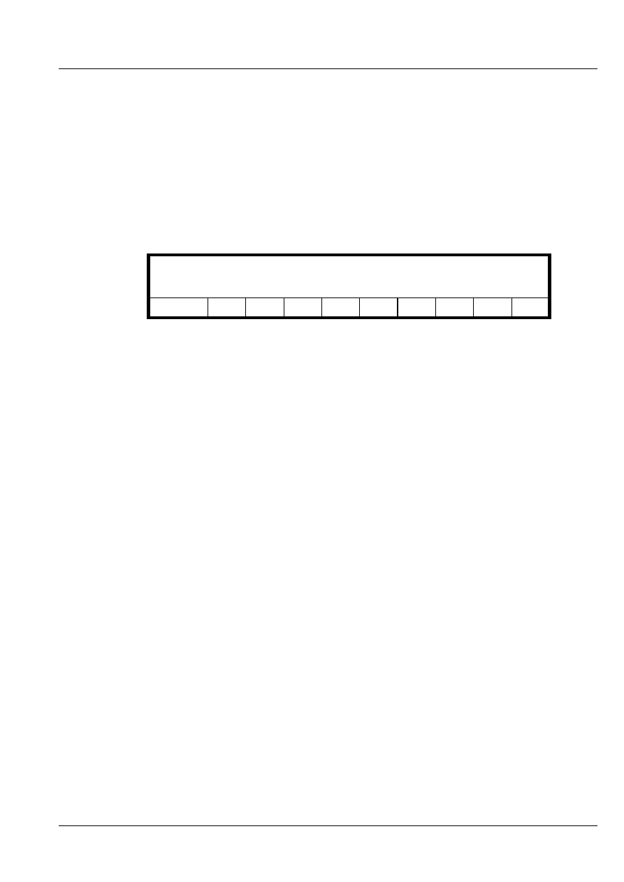
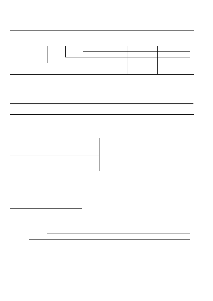
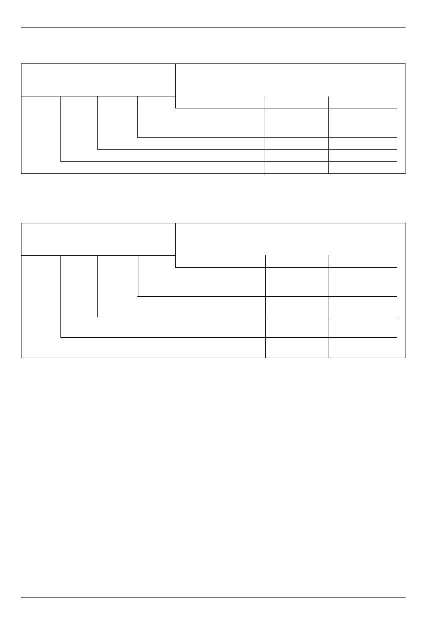
Readout on display:
Reading measured value block 17 ->
00000000 00000110 10000000 00000000
Meaning of 8-digit numerical block for readiness code in display field 2
1
2
3
4
5
6
7
8
Meaning
0
Ignore
1
Ignore
1
Ignore
0
Ignore
0
Ignore
0
Diagnosis of other systems
0
Diagnosis of fuel supply
0
Ignore
FABIA 2000
➤
1.9/96 TDI Engine, Fuel Injection
Self-diagnosis III
Edition 09.04
S00.5328.01.20
01-3
page
2
01
–
If the specified values are not reached, generate read-
iness code
⇒ 01-3
page 2.
–
Press
key.
–
Select function 06 „End output“ and switch ignition off.
Generating readiness code
Special tools, test and measuring equipment and
auxiliary items required
♦
Vehicle system tester -V.A.G 1552- with cable
-V.A.G 1551/3, 3A, 3B oder 3C-
Test conditions
•
All electrical consumers, e.g. lights and rear window
heater switched off.
•
Intake air temperature must be below 60
°
C
⇒
display
group 007, display field 3
•
Coolant temperature at least 83
°
C
⇒
display group
007, display block 4
Procedure
–
Connect vehicle system tester -V.A.G 1552-. Select
address word 01 „Engine electronics“
⇒
Chapter 01-
1.
Certain work steps must be carried out twice, in order to
achieve the readiness code.
Work step 1: Interrogating fault memory
–
Enter function
„Interrogate fault memory“ and
confirm with
.
The number of stored faults or „No fault recognised“ ap-
pears in the display.
If a fault is stored in the memory:
Meaning of 8-digit numerical block for readiness code in display field 4
1
2
3
4
5
6
7
8
Meaning
0
Ignore
0
Ignore
0
Ignore
0
Ignore
0
Ignore
0
Ignore
0
Ignore
0
Diagnosis of exhaust gas recirculation system
Note
0
2
Q
X faults detected
FABIA 2000
➤
1.9/96 TDI Engine, Fuel Injection
Self-diagnosis III
Edition 09.04
S00.5328.01.20
01-3
page
3
01
–
Rectify the faults by referring to the fault table
⇒
Chapter 01-2.
If no fault is stored:
–
Press .
Work step 2:Erasing fault memory
–
Enter function
„Erase fault memory“ and confirm
with .
The readiness code is erased each time the fault memory
is erased.
Readout on display:
If the ignition is switched off during „Interrogating fault
memory“ and „Erasing fault memory“, the fault memory is
not erased.
–
Press .
Work step 3: Switch off ignition
–
Wait at least 5 seconds with ignition OFF.
This point is important, because with certain diagnoses
the slowing down of the control unit must be ended. Oth-
erwise readiness code cannot be generated.
Work step 4: Switch on ignition
–
Wait at least 10 seconds with ignition ON.
Charge pressure sender is adapted to atmospheric pres-
sure sender.
Work step 5: 1. Testing fuel supply and other
systems
–
Start engine.
–
Function
„Read measured value block“ and then
select display group 001.
–
Increase engine speed for 5 seconds to 2500 rpm and
then run engine at idling speed.
Readout on display:
Work step 6: 1. Testing exhaust gas recircula-
tion
–
Increase engine speed to 1600 rpm up to 1700 rpm
and maintain it for at least 10 seconds in this range.
0
5
Q
Note
Vehicle system test ->
The fault memory is erased
Note
Note
0
8
Reading measured value block 1 ->
2500 rpm 4.6 mg/s 2.0
CA 94.2 C
FABIA 2000
➤
1.9/96 TDI Engine, Fuel Injection
Self-diagnosis III
Edition 09.04
S00.5328.01.20
01-3
page
4
01
Readout on display:
In this speed range, the exhaust gas recirculation is ac-
tive and the control difference is checked. (Condition for
generation of readiness code for exhaust gas recircula-
tion).
Work step 7: Switch off ignition
–
Wait at least 5 seconds with ignition OFF.
Work step 8: Switch on ignition
–
Wait at least 10 seconds with ignition ON.
Work step 9: 2. Testing fuel supply and other
systems
–
Start engine.
–
Function
„Read measured value block“ and then
select display group 001.
–
Increase engine speed for 5 seconds to 2500 rpm and
then run engine at idling speed.
Readout on display:
Work step 10: 2. Testing exhaust gas recircula-
tion
–
Increase engine speed to 1600 rpm up to 1700 rpm
and maintain it for at least 10 seconds in this range.
Readout on display:
–
Press .
–
Enter
for display group 017 and read readi-
ness code.
Readout on display:
Specification in display field 2: 00000110
Specification in display field 4: 00000000
–
Press .
–
If the specified values are not reached, repeat once
again procedure for generating readiness code
⇒ 01-3
page 2.
Work step 11: Interrogating fault memory
–
Enter function
„Interrogate fault memory“ and
confirm with
.
The number of stored faults or „No fault recognised“ ap-
pears in the display.
If a fault is stored in the memory:
Reading measured value block 1 ->
1650 rpm 4.1 mg/s 4.0
CA 93.2 C
0
8
Reading measured value block 1 ->
2500 rpm 4.6 mg/s 2.0
CA 94.2 C
Reading measured value block 1 ->
1650 rpm 4.1 mg/s 4.0
CA 93.2 C
C
0
1
7
Reading measured value block 17 ->
00000000 00000110 10000000 00000000
0
2
Q
X faults detected
FABIA 2000
➤
1.9/96 TDI Engine, Fuel Injection
Self-diagnosis III
Edition 09.04
S00.5328.01.20
01-3
page
5
01
–
Rectify the faults by referring to the fault table
⇒
Chapter 01-2 and again generate readiness code
⇒ 01-3
page 2.
If no fault is stored:
–
Press .
Readiness code was successfully generated, if no fault is
stored after two work sequences of the test procedure in
the fault memory for the engine control unit and if the fol-
lowing display appears in the channel 017.
Reading measured value block 17 ->
00000000 00000110 10000000 00000000

FABIA 2000
➤
1.9/96 TDI Engine, Fuel Injection
Self-diagnosis III
Edition 09.04
S00.5328.01.20
01-3
page
6
01
FABIA 2000
➤
1.9/96 TDI Engine, Fuel Injection
Self-diagnosis IV
Edition 09.04
S00.5328.01.20
01-4
page
1
01
01-4
Self-diagnosis IV
Reading measured value block
Special tools, test and measuring equipment and
auxiliary items required
♦
Vehicle system tester -V.A.G 1552- with cable
-V.A.G 1551/3, 3A, 3B oder 3C-
Test conditions
•
Coolant temperature must be at least 75
°
C.
•
All electrical components, e.g. lights and rear window
heater, must be switched off.
•
If vehicle is equipped with air conditioning, this must
be switched off.
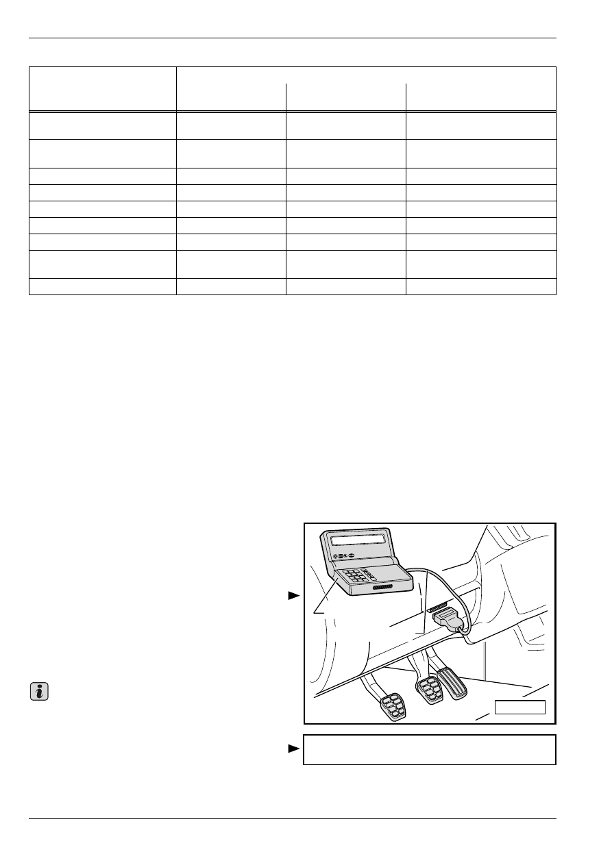
Procedure
–
Connect vehicle system tester -V.A.G 1552-. Start en-
gine and select the address word 01 „Engine electron-
ics“
⇒
Chapter 01-1.
–
Enter function 08 „Read measured value block“ and
confirm the entry with key
.
–
Enter display group
⇒ 01-4
page 1.
Display groups 001 to 022, engine idling
Display group 001 in idle (engine warm, coolant temperature not below 75
C)
Analysis: Display group 001, display field 2 - Injection rate
Q
Read measured value block 1
→
< Readout on display
xxx
rpm
xx.x
mg/s
x.xx
°
KW
xxx.x
°
C
1
2
3
4
< Display field
Specification
Analysis
Coolant temperature
75,0…110.0
°
C
---
Fuel delivery duration (set value)
3...8
°
KW
---
Injection rate
3,0…9.0 mg/s
⇒ 01-4
page 1
Engine speed
800…950 rpm
---
Display -V.A.G 1552-
Rectifying fault
below 3.0 mg/s
–
Check unit injectors
⇒
Chap. 23-3.
above 9.0 mg/s
–
Warm up engine by running at high revs and repeat test.
–
Check unit injectors
⇒
Chap. 23-3.
FABIA 2000
➤
1.9/96 TDI Engine, Fuel Injection
Self-diagnosis IV
Edition 09.04
S00.5328.01.20
01-4
page
2
01
Display group 002 in idle (engine warm, coolant temperature not below 75
C)
Analysis: Display group 002, display field 2 - Accelerator pedal position
Analysis: Display group 002, display field 3 - Op-
erating position
Display group 003 in idle (engine warm, coolant temperature not below 75
C)
Read measured value block 2
→
< Readout on display
xxx
rpm
xxx.x
%
x x x
xxx.x
°
C
1
2
3
4
< Display field
Specification
Analysis
Coolant temperature
75,0…110.0
°
C
---
Operating position
0 1 0
⇒ 01-4
page 2
Accelerator pedal position
0,0 %
⇒ 01-4
page 2
Engine speed
---
⇒ 01-4
page 1
Display -V.A.G 1552-
Rectifying fault
1…100,0%
–
Test accelerator pedal position sender -G79-
⇒
Current Flow Diagrams,
Electrical Fault Finding and Fitting Locations.
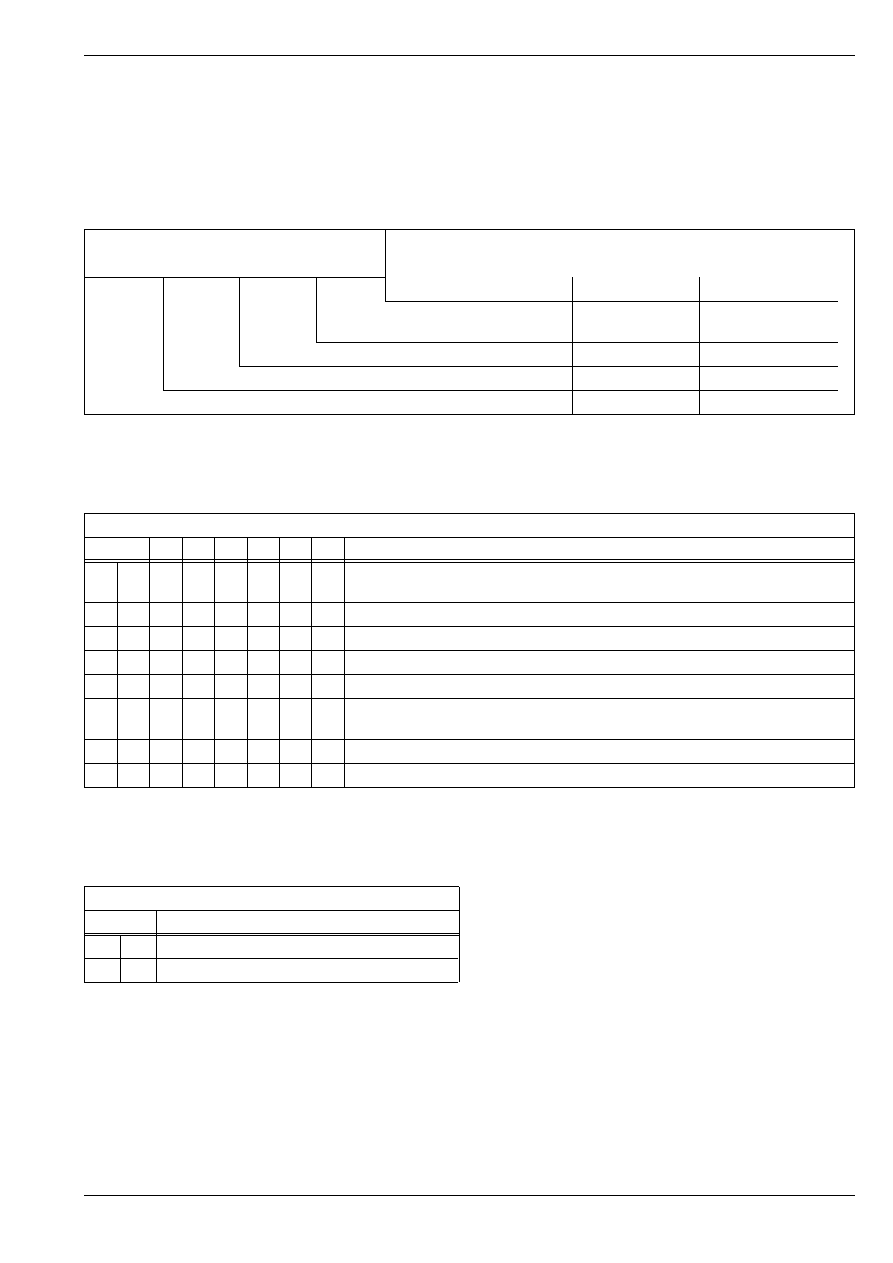
Meaning, if display positions = 1
X
X
X
Operating position
1
Air conditioning switched on
1
Idling switch closed (accelerator pedal
not pressed)
0
Ignore
Read measured value block 3
→
< Readout on display
xxx
rpm
xxx
mg/s
xxx
mg/s
xxx
%
1
2
3
4
< Display field
Specification
Analysis
On/off ratio (actuation) of
exhaust gas recirculation
valve
40…75%
---
drawn in air mass (actual)
210...350 mg/s
⇒ 01-4
page 3
drawn in air mass (nominal)
230...310 mg/s
⇒ 01-4
page 3
Engine speed
---
⇒ 01-4
page 1
FABIA 2000
➤
1.9/96 TDI Engine, Fuel Injection
Self-diagnosis IV
Edition 09.04
S00.5328.01.20
01-4
page
3
01
Analysis: Display group 003, display field 2 - inducted air mass (set value)
Analysis: Display group 003, display field 3 - inducted air mass (actual value)
Display group 004 in idle (engine warm, coolant temperature not below 75
C)
Analysis: Display group 004, display field 2 - commencement of injection (set value)
Analysis: Display group 004, display field 4 - Synchronizing angle
Display -V.A.G 1552-
Rectifying fault
above 310 mg/s
–
Warm up engine by running at high revs and repeat test.
Display -V.A.G 1552-
Rectifying fault
below 210 mg/s
–
Test exhaust gas recirculation
⇒
Chap. 23-4.
–
Inspect intake system for leaks.
above 350 mg/s
–
Warm up engine by running at high revs and repeat test.
–
Engine idles for too long, briefly blip throttle.
–
Test air mass meter -G70-
⇒
Current Flow Diagrams, Electrical Fault Find-
ing and Fitting Locations.
Read measured value block 4
→
< Readout on display
xxx
rpm
xx.x
°
b. TDC
xx.x
°
KW
xx.x
°
KW
1
2
3
4
< Display field
Specification
Analysis
Synchronizing angle
-3…+3
°
KW
⇒ 01-4
page 3
Fuel delivery duration (set value)
3,0…8.0
°
KW
---
Commencement of injection (set value)
4
°
BTDC…2
°
ATDC
⇒ 01-4
page 3
Engine speed
---
⇒ 01-4
page 1
Display -V.A.G 1552-
Rectifying fault
less than 4
°
BTDC
–
Engine too cold, warm up engine by running at high revs and repeat test.
Display -V.A.G 1552-
Rectifying fault
above 3
°
KW or under -3
°
KW
–
Test camshaft position sensor -G40-
⇒
Current Flow Diagrams, Electrical
Fault Finding and Fitting Locations.
–
Inspect position of camshaft and rotor
⇒
1.9/96 TDI Engine, Mechanics;
Rep. Gr. 15.
FABIA 2000
➤
1.9/96 TDI Engine, Fuel Injection
Self-diagnosis IV
Edition 09.04
S00.5328.01.20
01-4
page
4
01
Display group 006 in idle (engine warm, coolant temperature not below 75
C)
Analysis: Display group 006, display field 2 -
Brake pedal or clutch pedal monitoring
Analysis: Display group 006, display field 4 - Op-
erating condition of cruise control system
Read measured value block 6
→
< Readout on display
xxx
km/h
xxx
xx.x
%
xxx
1
2
3
4
< Display field
Specification
Analysis
Operating condition of the
cruise control system
xxx
⇒ 01-4
page 4
Accelerator pedal position
0%
⇒ 01-4
page 2
Status of the brake and clutch pedal switch
000
⇒ 01-4
page 4
Vehicle speed
0 km/h
---
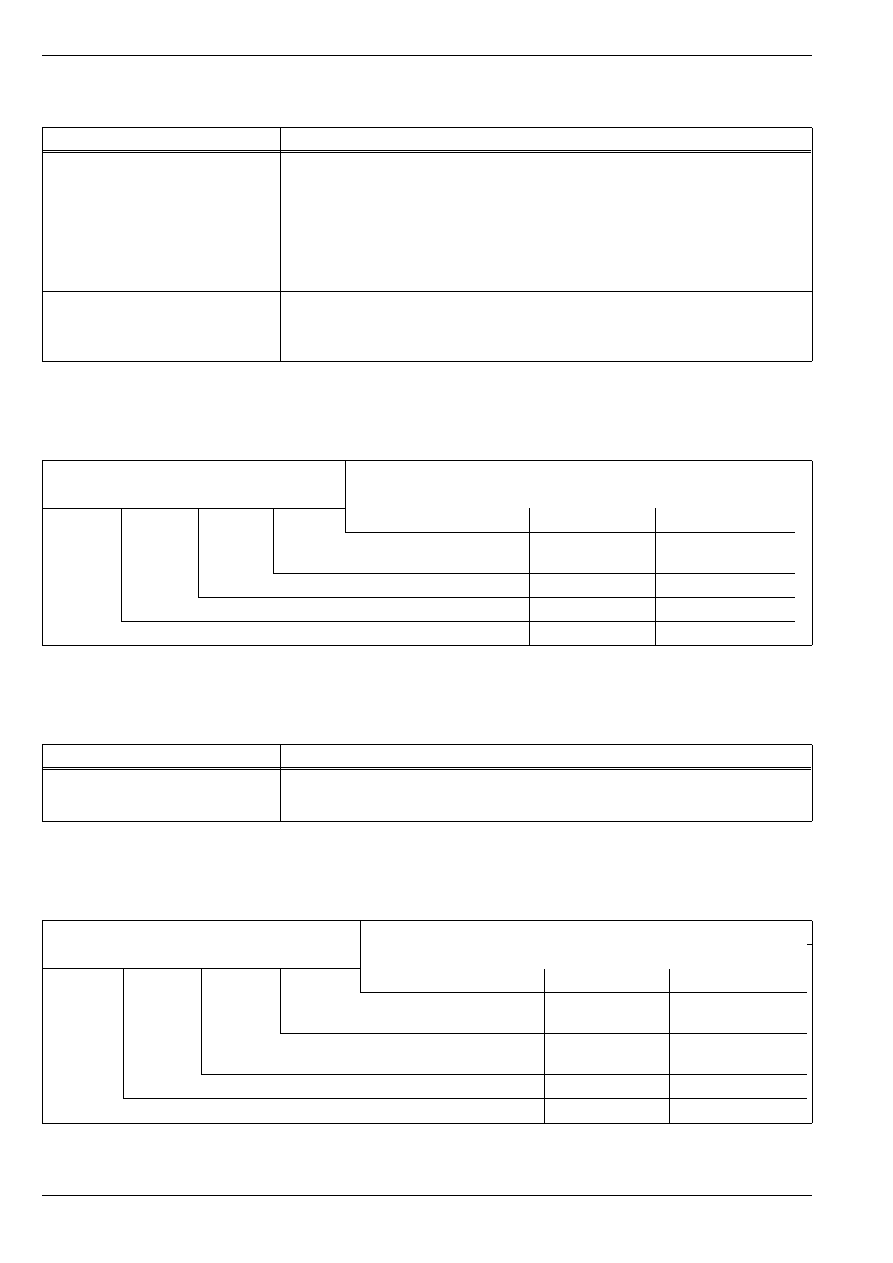
Meaning, if display positions = 1
X
X
X
Operating position
1
Brake light switch -F- closed (brake
pedal operated)
1
Brake pedal switch -F47- opened
(brake pedal operated)
1
Clutch pedal switch -F36- opened
(clutch pedal operated)
Dis-
play
Operating position
0
Vehicles with activated cruise control system,
switch in position „OFF“
1
Vehicles with activated cruise control system,
switch in position „ON“
255
Vehicle without cruise control system or
cruise control system function in engine con-
trol unit not activated
FABIA 2000
➤
1.9/96 TDI Engine, Fuel Injection
Self-diagnosis IV
Edition 09.04
S00.5328.01.20
01-4
page
5
01
Display group 007 with ignition switched on (engine cool and standing)
Analysis: Display group 007, display field 1 - Fuel temperature
Analysis: Display group 007, display field 3 - Intake manifold temperature
Analysis: Display group 007, display field 4 - Coolant temperature
Read measured value block 7
→
< Readout on display
xxx.x
°
C
xxx
%
xxx.x
°
C
xxx.x
°
C
1
2
3
4
< Display field
Specification
Analysis
Coolant temperature
approx. ambient
temperature
1)
1)
It is not possible to give a nominal value indication for temperatures. Once the engine has cooled down the temperatures of the fuel, intake
manifold and coolant must approximately correspond with the ambient temperature. If there is a marked value difference check the relevant
sender.
⇒ 01-4
page 5
Intake manifold temperature
approx. ambient
temperature
1)
⇒ 01-4
page 5
Status of the fuel cooling
0%
---
Fuel temperature
approx. ambient
temperature
1)
⇒ 01-4
page 5
Display -V.A.G 1552-
Rectifying fault
continuously 40.5
°
C
–
Inspecting Fuel temperature sender -G81-
⇒
Chap. 23-1.
Display -V.A.G 1552-
Rectifying fault
continuously 135.9
°
C
–
Inspecting Intake manifold temperature sender - G72-
⇒
Chap. 23-1.
Display -V.A.G 1552-
Rectifying fault
continuously -5.4
°
C
–
Inspecting coolant temperature sender -G62-
⇒
Chap. 23-1.
In the event of a fault the fuel temperature is displayed instead.
FABIA 2000
➤
1.9/96 TDI Engine, Fuel Injection
Self-diagnosis IV
Edition 09.04
S00.5328.01.20
01-4
page
6
01
Display group 011 in idle (engine warm, coolant temperature not below 75
C)
Display group 013 in idle (engine warm, coolant temperature not below 75
C)
Analysis: Display group 013, display field 1
through 4 - Idle smoothness regulator
♦
The injection system has an idle smoothness regula-
tor. It is possible to detect differences in performance
between individual cylinders (part tolerances, injector
flow, compression etc.) and to compensate for these
by selectively metering the quantity injected in the
idling speed range.
♦
Differences are detected in the idling speed range on
the basis of the signal supplied by the engine speed
sender which supplies four signals to the control unit
for each crankshaft revolution. If the signals have the
same rhythm, the cylinder have the same output. If a
cylinder has a lower output, the crankshaft will need
more time for the next half crankshaft rotation. As op-
posed to this a high output cylinder will accelerate the
crankshaft to such an extent that it will need less time.
♦
Once the control unit has identified a deviation, the
relevant cylinder will immediately be supplied with a
greater or smaller injection rate until the engine again
runs „smoothly“.
Read measured value block 11
→
< Readout on display
xxx
rpm
xxxx
mbar
xxxx
mbar
xxx
%
1
2
3
4
< Display field
Specification
Analysis
On/off ratio (actuation) of
solenoid valve for charge
pressure control -N75-
20...50%
---
Charge pressure (actual value)
900...1150 mbar
---
Charge pressure (specified value)
900...1100 mbar
---
Engine speed
---
⇒ 01-4
page 1
Read measured value block 13
→
< Readout on display
x.xx
mg/s
x.xx
mg/s
x.xx
mg/s
x.xx
mg/s
1
2
3
4
< Display field
Specification
Analysis
Smooth running control -
injected quantity cylinder
4
-2,80…+2.80
mg/s
⇒ 01-4
page 6
Smooth running control - injected
quantity cylinder 3
-2,80…+2.80
mg/s
⇒ 01-4
page 6
Smooth running control - injected quantity cylin-
der 2
-2,80…+2.80
mg/s
⇒ 01-4
page 6
Smooth running control - injected quantity cylinder 1
-2,80…+2.80
mg/s
⇒ 01-4
page 6
FABIA 2000
➤
1.9/96 TDI Engine, Fuel Injection
Self-diagnosis IV
Edition 09.04
S00.5328.01.20
01-4
page
7
01
♦
+… mg/s: The relevant cylinder has less output and is
therefore supplied with more fuel.
♦
-… mg/s: The relevant cylinder has more output and
is therefore supplied with less fuel.
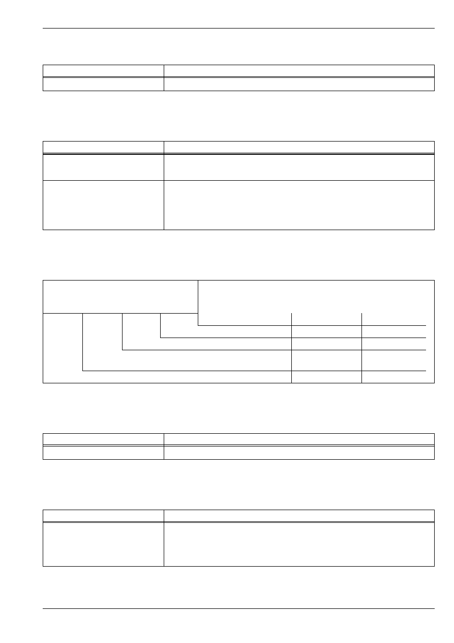
Display group 016 in idle
Analysis: Display group 016, display field 2 - Auxiliary heating (operating condition)
Analysis: Display group 016, display field 3 -
Control of the heating elements
Read measured value block 16
→
< Readout on display
xxx %
xxxxxxxx
xx
xx.x V
1
2
3
4
< Display field
Specification
Analysis
Supply voltage of the en-
gine control unit
12,5…14.5 V
⇒ 01-4
page 8
Heating element control
xx
⇒ 01-4
page 7
Auxiliary heating (operating condition)
xxxxxxxx
⇒ 01-4
page 7
Generator capacity
5…95%
---
Meaning, if display positions = 1
X
X
X
X
X
X
X
X
Additional heating deactivated, because:
1
Coolant temperature greater than 70…80
°
C or intake air temperature great-
er than +5
°
C
1
AC generator defective
1
Battery voltage below 9 V
1
Engine speed less than 860 rpm
1
Engine start within the last 10 seconds
1
Coolant temperature sender -G62- or Intake manifold temperature sender
-G72- or end stage for auxiliary heating defective
1
Ignore
1
Ignore
Meaning, if display positions = 1
X
X
Operating position
1
Low heat output relay -J359- on
1
High heat output relay -J360- on
FABIA 2000
➤
1.9/96 TDI Engine, Fuel Injection
Self-diagnosis IV
Edition 09.04
S00.5328.01.20
01-4
page
8
01
Analysis: Display group 016, display field 4 - supply voltage of engine control unit
Display group 018 in idle
Analysis: Display group 018, display field 1 through 4 - Display of the conditon of the unit injectors
Display group 022, engine idling
Display -V.A.G 1552-
Rectifying fault
below 12.5 V
–
Test AC generator and battery voltage, charge battery
⇒
Electrical System;
Rep. Gr. 27.
–
Increase engine speed slightly for a few minutes and switch off additional
consumers.
–
Test supply voltage of engine control unit
⇒
Chap. 23-5.
–
Rectify any current drain.
above 14.5 V
–
Test voltage regulator, replace if necessary
⇒
Electrical System;
Rep. Gr. 27.
–
Remove start aid cable or quick charger.
Read measured value block 18
→
< Readout on display
xx
xx
xx
xx
1
2
3
4
< Display field
Specification
Analysis
Unit injector solenoid
valve cyl. 4
0
⇒ 01-4
page 8
Unit injector solenoid valve cyl. 3
0
⇒ 01-4
page 8
Unit injector solenoid valve cyl. 2
0
⇒ 01-4
page 8
Unit injector solenoid valve cyl. 1
0
⇒ 01-4
page 8
Display -V.A.G 1552-
Rectifying fault
If number instead of zero
–
Test injector unit
⇒
Chap. 23-3.
–
Inspecting fuel supply
⇒
1.9/96 TDI Engine, Mechanics; Rep. Gr. 20.
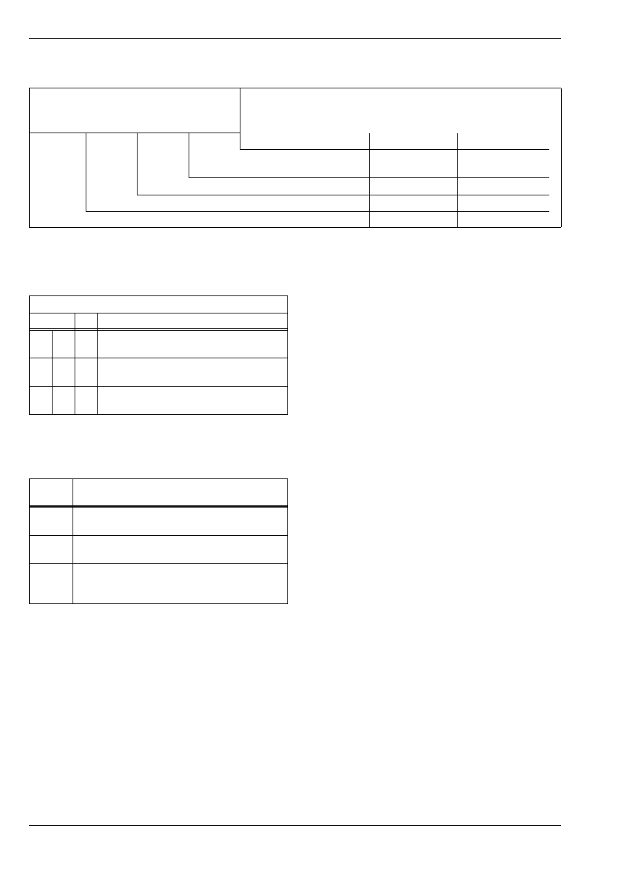
Read measured value block 22
→
< Readout on display
x
xxxxxx
x
x
1
2
3
4
< Display fields
Specification
Analysis
Operating state of air con-
ditioning
0
—
Operating state of charge pressure
control
0
—
Operating state of cruise control
xxxxxx
⇒ 01-4
page 9
Operating condition of the cruise control system
x
⇒ 01-4
page 9
FABIA 2000
➤
1.9/96 TDI Engine, Fuel Injection
Self-diagnosis IV
Edition 09.04
S00.5328.01.20
01-4
page
9
01
Analysis: Display group 022, display field 1 - operating state of cruise control system
Analysis: Display group 022, display field 2 - op-
erating state of cruise control system
Display groups 004 through 011 at full
load
♦
Accelerate vehicle at full throttle before inspecting.
♦
The measured values must be read off or printed out
once an engine speed of 3000 rpm is reached (2nd
person required).
♦
Pay attention to safety precautions for test drives
⇒
Chapter 23-1.
Operating condition of the cruise control system
0
Vehicle without CCS, or CCS function in engine control unit not activated
1
Vehicles with activated CCS, switch in position „OFF“
9
Vehicles with activated CCS, switch in position „ON“
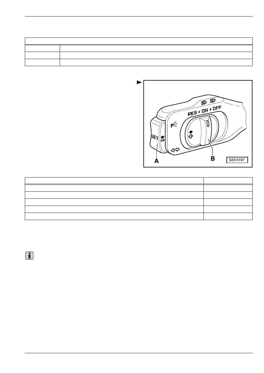
Cruise control
Display field 2
Switch B on „ON“
000011
Switch B on „RES“
001011
Switch A operated
000111
Switch B to „OFF“ before operating point
000001
Switch B to „OFF“ locked
000000
Note
FABIA 2000
➤
1.9/96 TDI Engine, Fuel Injection
Self-diagnosis IV
Edition 09.04
S00.5328.01.20
01-4
page
10
01
Display group 004 under full load (test drive in 2nd gear coolant temperature not below 75
C)
Display group 008 under full load (test drive in 2nd gear coolant temperature not below 75
C)
Analysis: Display group 008, display field 2 - Injection rate (driver's instruction)
Analysis: Display group 008, display field 3 - Injection rate limit over speed (torque limit)
Read measured value block 4
→
< Readout on display
xxx
rpm
xx.x
°
b. TDC
xx.x
°
KW
x.xx
°
KW
1
2
3
4
< Display field
Specification
Analysis
Synchronizing angle
-3...+3 KW
---
Fuel delivery duration (set value)
16…28
°
KW
---
Commencement of injection (set value)
13
°
BTDC…21
°
BTDC
---
Engine speed
2800…3200 rpm
---
Read measured value block 8
→
< Readout on display
xxx
rpm
xx.x
mg/s
xx.x
mg/s
xx.x
mg/s
1
2
3
4
< Display field
Specification
Analysis
Injection rate limit based
on drawn in air mass
(smoke prevention)
47,0…60.0 mg/s
⇒ 01-4
page 11
Injection rate limit based on engine
speed (torque limit)
47,0…51.0 mg/s
⇒ 01-4
page 10
Injection rate (driver's instruction)
65,0…70.0 mg/s
⇒ 01-4
page 10
Engine speed
2800…3200 rpm
---
Display -V.A.G 1552-
Rectifying fault
below 65.0 mg/s
–
Repeat test at full throttle.
–
Test accelerator pedal position sender -G79-
⇒
Current Flow Diagrams,
Electrical Fault Finding and Fitting Locations.
Display -V.A.G 1552-
Rectifying fault
below 47.0 mg/s
–
Read off set value at 3000 rpm.
FABIA 2000
➤
1.9/96 TDI Engine, Fuel Injection
Self-diagnosis IV
Edition 09.04
S00.5328.01.20
01-4
page
11
01
Analysis: Display group 008, display field 4 - Injection rate limit (smoke prevention)
Display group 011 under full load (test drive in 2nd gear coolant temperature not below 75
C)
Analysis: Display group 011, display field 3 - intake manifold pressure (charge pressure)
Display group 125 - CAN databus
Display group 125 with ignition switched on
Display -V.A.G 1552-
Rectifying fault
below 47.0 mg/s
–
Test air mass meter -G70-
⇒
Current Flow Diagrams, Electrical Fault Find-
ing and Fitting Locations.
–
Test exhaust gas recirculation
⇒
Chap. 23-4.
Read measured value block 11
→
< Readout on display
xxxx
rpm
xxxx
mbar
xxxx
mbar
xxx
%
1
2
3
4
< Display field
Specification
Analysis
On/off ratio (actuation) of
solenoid valve for charge
pressure control -N75-
40...95%
---
Charge pressure (actual value)
2100...2600
mbar
---
Charge pressure (specified value)
2200...2400
mbar
---
Engine speed
2800...3200 rpm
Display -V.A.G 1552-
Rectifying fault
below 2100 mbar
or
over 2600 mbar
–
Inspecting charge pressure control
⇒
1.9/96 TDI Engine, Mechanics;
Rep. Gr. 21.
Read measured value block 125
→
< Readout on display
ABS 1
Combi 1
Airbag 1
1
2
3
4
< Display field
Specification
Analysis
Airbag control unit
Airbag 1
⇒ 01-4
page 12
Dash panel insert CU
Combi 1
⇒ 01-4
page 12
ABS control unit
ABS 1
⇒ 01-4
page 12
not assigned
---
---

FABIA 2000
➤
1.9/96 TDI Engine, Fuel Injection
Self-diagnosis IV
Edition 09.04
S00.5328.01.20
01-4
page
12
01
Analysis: Display group 125, display field 2, 3 and 4
Display -V.A.G 1552-
Rectifying fault
0
–
Test CAN databus
⇒
Chap. 23-6.

FABIA 2000
➤
1.9/96 TDI Engine, Fuel Injection
Diesel Direct Injection System
Edition 09.04
S00.5328.01.20
23-1
page
1
23
23-1
Diesel Direct Injection
System
Safety measures
Observe the following points to prevent injury to persons
and/or damage to the injection and preheating system:
♦
Disconnect and connect wires of the injection and pre-
heating system and measuring device wires when the
ignition is switched off.
♦
When the battery is disconnected and reconnected,
carry out rework
⇒
Electrical System; Rep. Gr. 27.
If test and measuring devices are required during test
drives observe the following:
♦
Always secure the test and measuring devices on the
rear seat and have a second person operate them
there. If the test and measuring equipment is operated
from the front passenger seat, this can result in inju-
ries to the persons sitting on that seat in the event of
an accident which involves the front passenger airbag
being deployed.
Rules of cleanliness
Pay careful attention to the following rules of cleanliness
when working on the fuel supply or fuel injection systems:
♦
Thoroughly clean the connection points and their sur-
roundings before releasing.
♦
Place removed parts on a clean surface and cover. Do
not use fuzzy cloths!
♦
Carefully cover or close opened components if the re-
pair is not completed immediately.
♦
Only install clean parts. Remove spare parts from
their wrapping immediately before fitting. Do not use
parts that have been stored without wrapping (e.g. in
tool cabinets etc.).
♦
When the system is open: avoid working with com-
pressed air. Avoid moving the vehicle.
♦
Also make sure no diesel fuel runs onto the coolant
hoses. If this is the case clean the hoses immediately.
Replace immediately any hoses which have suffered
damage.
23 – Fuel Formation, Injection
FABIA 2000
➤
1.9/96 TDI Engine, Fuel Injection
Diesel Direct Injection System
Edition 09.04
S00.5328.01.20
23-1
page
2
23
Overview of fitting locations
Components A through H are not represented in the overview figure.
A - Diesel direct injection system
relay -J322-
❑
on relay carrier
⇒
Current
Flow Diagrams, Electrical
Fault Finding and Fitting Lo-
cations
B - Glow plug relay -J52-
❑
on relay carrier
⇒
Current
Flow Diagrams, Electrical
Fault Finding and Fitting Lo-
cations
C - Low heat output relay -J359-
❑
on relay carrier
⇒
Current
Flow Diagrams, Electrical
Fault Finding and Fitting Lo-
cations
D - High heat output relay -J360-
❑
on relay carrier
⇒
Current
Flow Diagrams, Electrical
Fault Finding and Fitting Lo-
cations
E - Fuel pump relay -J17-
❑
on relay carrier
⇒
Current
Flow Diagrams, Electrical
Fault Finding and Fitting Lo-
cations
F - Sender for accelerator pedal
position -G79-
❑
in footwell on the accelerator
pedal
⇒
Fig. 1 in
23-1
page 3
G - Brake light switch -F- and
Brake pedal switch -F47-
❑
in footwell on the brake pedal
⇒
Fig. 1 in
23-1
page 3
H - Clutch pedal switch -F36-
❑
in footwell on the clutch pedal
⇒
Fig. 1 in
23-1
page 3
1 - Valve block
❑
Component parts of the valve block are:
❑
intake manifold flap change-over valve -N239-, specified resistance 25...45
Ω
❑
Solenoid valve for exhaust gas recirculation -N18-, specified resistance 14...20
Ω
❑
solenoid valve for charge pressure control -N75-, specified resistance 25...45
Ω
2 - Mechanical exhaust gas recirculation valve
3 - Sender for the coolant temperature -G62-
❑
Specified resistance
⇒
Fig. 2 in
23-1
page 3
4 - Air mass meter -G70-
5 - Diesel direct injection system control unit -J248-
6 - Fuel temperature sender -G81-
❑
Specified resistance
⇒
Fig. 3 in
23-1
page 4
7 - Connector
❑
3-pin, grey
❑
for engine speed sender -G28-
❑
3-pin, black
S23-0156
7
1
2
3
4
5
11
10
9
8
6
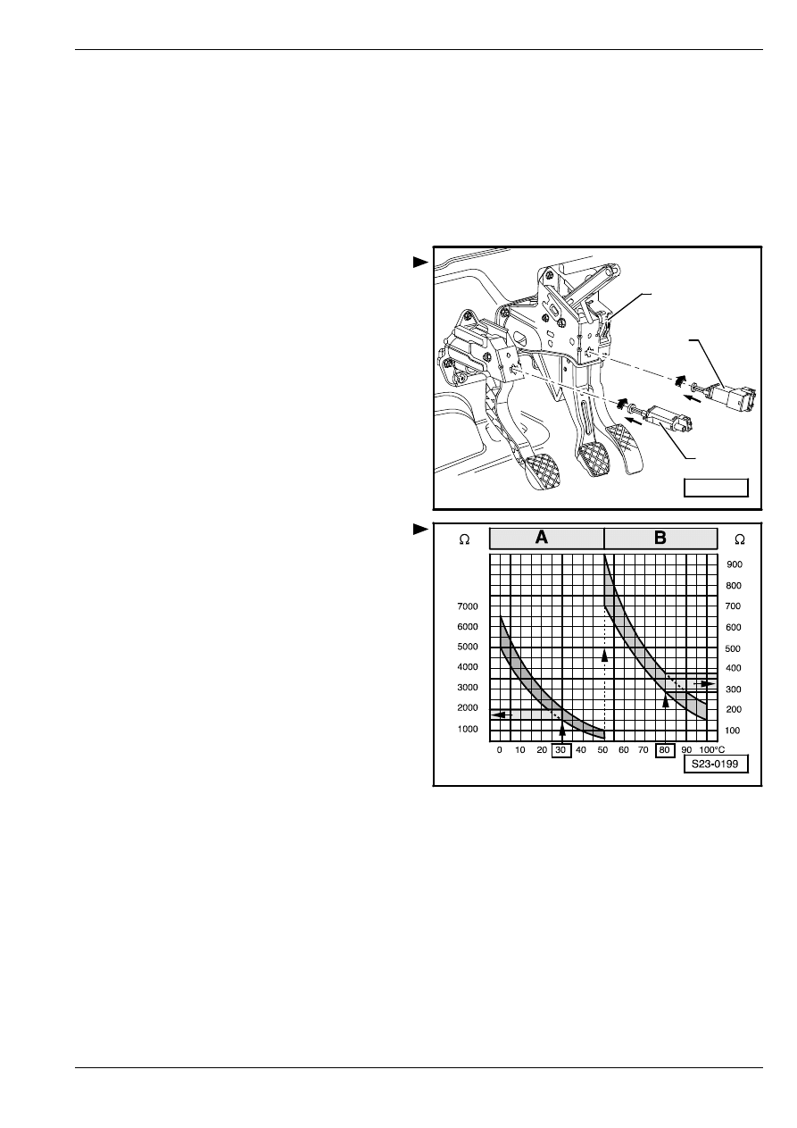
FABIA 2000
➤
1.9/96 TDI Engine, Fuel Injection
Diesel Direct Injection System
Edition 09.04
S00.5328.01.20
23-1
page
3
23
❑
for the camshaft position sensor -G40-
8 - Engine speed sender -G28-
❑
specified resistance between contacts 1 and 2: 450...550
Ω
9 - Camshaft position sensor -G40-
10 - Intake manifold pressure sender -G71- with intake manifold temperature sender -G72-
❑
Specified resistance
⇒
Fig. 2 in
23-1
page 3
11 - Fuel filter
❑
repairing
⇒
1.9/96 TDI Engine, Mechanics; Rep. Gr. 20
Fig. 1:
Components in footwell
1 - Clutch pedal switch -F36-
2 - Brake light switch -F- and Brake pedal switch -F47-
3 - Sender for accelerator pedal position -G79-
Fig. 2:
Resistance of coolant temperature sender
-G62- and of intake manifold temperature
sender -G72-
The specification in field -A- applies to the temperature
range 0 to 50
°
C, specification in field -B- applies to the
temperature range 50 to 100
°
C.
Read out examples:
♦
The specification for a temperature of 30
°
C is 1500 to
2000
Ω
♦
The specification for a temperature of 80
°
C is 275 to
375
Ω
S24-0374
2
1
3
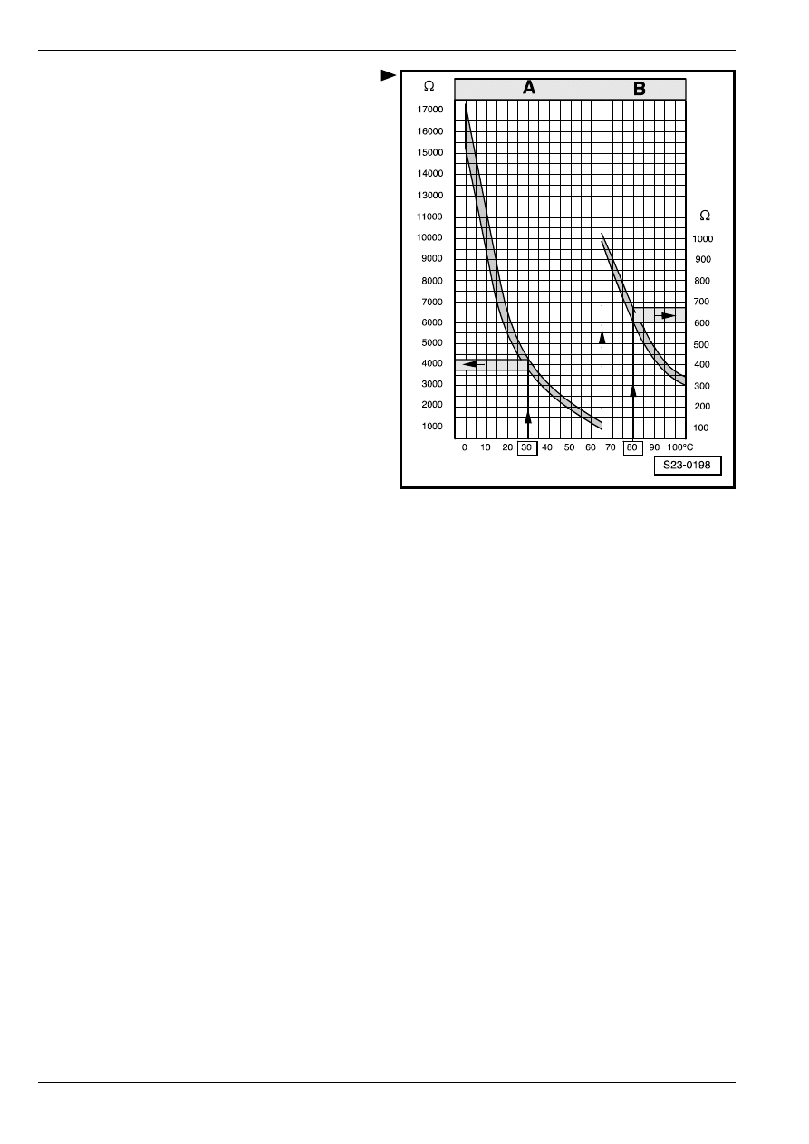
FABIA 2000
➤
1.9/96 TDI Engine, Fuel Injection
Diesel Direct Injection System
Edition 09.04
S00.5328.01.20
23-1
page
4
23
Fig. 3:
Resistance of fuel temperature sender -G81-
The specification in field -A- applies to the temperature
range 0 to 65
°
C, specification in field -B- applies to the
temperature range 65 to 100
°
C.
Read out examples:
♦
The specification for a temperature of 30
°
C is 3790 to
4270
Ω
♦
The specification for a temperature of 80
°
C is 600 to
660
Ω
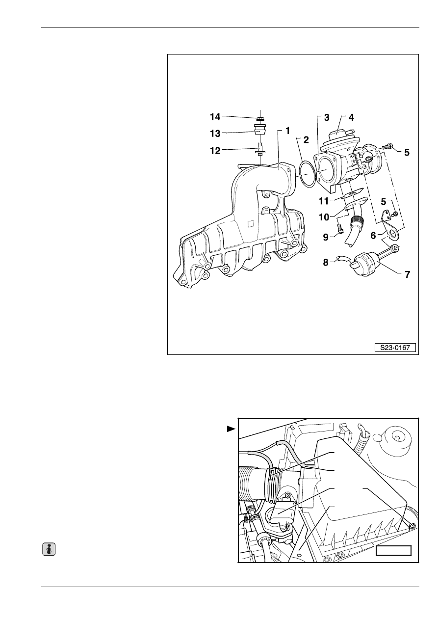
FABIA 2000
➤
1.9/96 TDI Engine, Fuel Injection
Diesel Direct Injection System
Edition 09.04
S00.5328.01.20
23-1
page
5
23
Disassembling and assembling intake manifold
1 - Intake manifold
2 - O-ring
❑
replace
3 - Induction pipe
❑
with exhaust gas recircula-
tion valve and intake mani-
fold flap
4 - Mechanical exhaust gas recir-
culation valve
5 - 10 Nm
6 - Bracket
7 - Vacuum setting element
8 - Vacuum hose
❑
of valve block
9 - 25 Nm
10 - Exhaust return pipe
❑
to exhaust pipe
11 - Gasket
❑
replace
12 - 6 Nm
13 - Sealing sleeve
14 - 5 Nm
Removing and installing air filter
Removing
–
Loosen spring strap clamp -1- on the air guide hose
and remove the hose from the air filter.
–
Disconnect ventilation hose -2- and the plug on the air
mass meter -3-.
–
Remove the air deflector -4- from the air filter.
–
Unscrew the fixing screw -5- from the air filter (tighten-
ing torque: 8 Nm).
–
Carefully remove air filter from the top.
Installing
Pay attention to correct positioning of the stop buffer on
the bottom part of the air filter (front and rear side).
1
2
3
4
5
S23-0125
Note
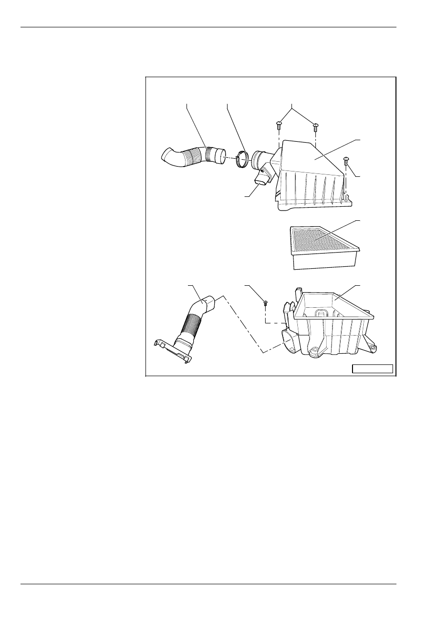
FABIA 2000
➤
1.9/96 TDI Engine, Fuel Injection
Diesel Direct Injection System
Edition 09.04
S00.5328.01.20
23-1
page
6
23
–
Installation is carried out in the reverse order.
Disassembling and assembling the air filter
1 - Air guide hose
❑
To intake manifold
❑
Check fitting position
2 - Spring strap clip
3 - 2 Nm
4 - Top part of air filter cover
5 - Filter insert
6 - Bottom part of the air filter
cover
7 - 2 Nm
8 - Air deflector
❑
to the lock carrier
9 - Air mass meter -G70-
❑
inspect
⇒
Chapter 23-3
S23-0124
7
9
1
2
3
4
5
6
8
3

FABIA 2000
➤
1.9/96 TDI Engine, Fuel Injection
Disassembling and assembling the unit injector
Edition 07.03
S00.5328.00.20
23-2
page
1
23
23-2
Disassembling and as-
sembling the unit injector
⇒
Workshop Manual OCTAVIA 1.9 l/96 kW (TDI) En-
gine, Fuel Injection and Glow Plug System; Rep. Gr. 23

FABIA 2000
➤
1.9/96 TDI Engine, Fuel Injection
Disassembling and assembling the unit injector
Edition 07.03
S00.5328.00.20
23-2
page
2
23

FABIA 2000
➤
1.9/96 TDI Engine, Fuel Injection
Testing components
Edition 07.03
S00.5328.00.20
23-3
page
1
23
23-3
Testing components
⇒
Workshop Manual OCTAVIA 1.9 l/96 kW (TDI) En-
gine, Fuel Injection and Glow Plug System; Rep. Gr. 23

FABIA 2000
➤
1.9/96 TDI Engine, Fuel Injection
Testing components
Edition 07.03
S00.5328.00.20
23-3
page
2
23
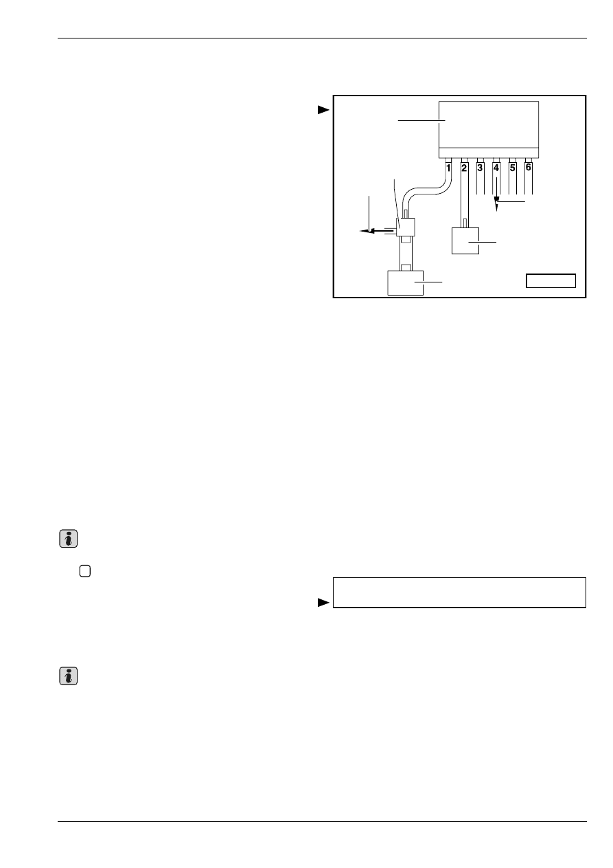
FABIA 2000
➤
1.9/96 TDI Engine, Fuel Injection
Testing exhaust gas recirculation
Edition 07.03
S00.5328.00.20
23-4
page
1
23
23-4
Testing exhaust gas recir-
culation
Connection diagram of vacuum hoses
for exhaust gas recirculation
1 - Valve block
2 - Non-return valve
3 - To the brake servo unit
4 - Vacuum pump
5 - Mechanical exhaust gas recirculation valve
6 - To air filter
Testing exhaust gas recirculation
Special tools, test and measuring equipment and
auxiliary items required
♦
Vehicle system tester -V.A.G 1552-
♦
Diagnostic cable -V.A.G 1551/3, 3A, 3B oder 3C-
Test sequence
The exhaust gas recirculation function is checked in func-
tion 04 (basic setting). As a result of this procedure the
exhaust gas recirculation valve is pulsed every 10 sec-
onds, so that the extreme values for the exhaust gas re-
circulation (air mass meter) can be read off in measured
value block 003 in display field 3.
–
Connect vehicle system tester -V.A.G 1552-. Start en-
gine and select address word 01 „Engine electronics“
⇒
Chapter 01-1.
–
Enter function 04 „basic setting“ and select display
group number 003.
After selecting display group number 003 and confirming
with
, the idling speed is increased by the engine con-
trol unit in display field 1 to 1380…1420 rpm.
The display in display field 2 must switch between EGR
not active and EGR active every 10 seconds.
The following readouts must fluctuate in display fields 3
and 4:
If a constant value of 539 mg/stroke and higher is shown
in display field 3, test the air mass meter
⇒
Chapter 23-3.
S23-0155
1
3
2
4
5
6
Note
Q
System in basic setting 3 ->
1410 rpm EGR not active 450 mg/H
Note

FABIA 2000
➤
1.9/96 TDI Engine, Fuel Injection
Testing exhaust gas recirculation
Edition 07.03
S00.5328.00.20
23-4
page
2
23
If the specified values are not reached:
–
Inspecting mechanical exhaust gas recirculation valve
⇒
1.9/96 TDI Engine, Mechanics; Rep. Gr. 26.
–
Inspect
⇒ 23-4
page 1 vacuum hoses to see that
they are connected properly.
–
Test solenoid valve for activated charcoal filter system
-N18- with final control diagnosis
⇒
Chapter 01-1.
EGR not active:
Specification in display field 3: 440…600 mg/H
specified value in display field 4: 18…22 %
EGR active:
Specification in display field 3: 160…340 mg/H
specified value in display field 4: 63…67 %
FABIA 2000
➤
1.9/96 TDI Engine, Fuel Injection
Engine control unit
Edition 09.04
S00.5328.01.20
23-5
page
1
23
23-5
Engine control unit
Testing voltage supply for engine con-
trol unit
Special tools, test and measuring equipment and
auxiliary items required
♦
Vehicle system tester -V.A.G 1552- with cable
-V.A.G 1551/3, 3A, 3B oder 3C-
♦
Handheld multimeter (e.g. -V.A.G 1526 A-)
♦
Measuring tool set (e.g. -V.A.G 1594 A- or
- V.A.G 1594 C-)
♦
Test box -V.A.G 1598/31-
Test conditions
•
Fuses o.k.
•
Battery voltage at least 11.5 volts
•
AC generator O.K.
Test sequence
–
Connect vehicle system tester -V.A.G 1552-. Switch
ignition on and enter address word 01 „Engine elec-
tronics“
⇒
Chapter 01-1.
–
Enter function 08 „read measured value block“ and
select display group 012.
Readout on display:
–
Read off value indicated in display field 3.
Specified value: approx. battery voltage (constant)
–
Enter function 06 „End output“ and confirm with
.
If the value displayed fluctuates or if the battery voltage is
not reached:
–
Switch off ignition.
–
Connect test box -V.A.G 1598/31- at the wiring loom
of the engine control unit
⇒
Chap. 23-3.
–
Connect handheld multimeter as follows:
–
Switch on ignition.
–
Measure once again the voltage between the bushes.
Reading measured value block 12 ->
11111111 0.00 12.5 V 28.5
C
Q
Test box -V.A.G 1598/
31-, bush
Specification
1, 2 + 4, 5
approx. 0 V
37 + 4, 5
approx. 0 V
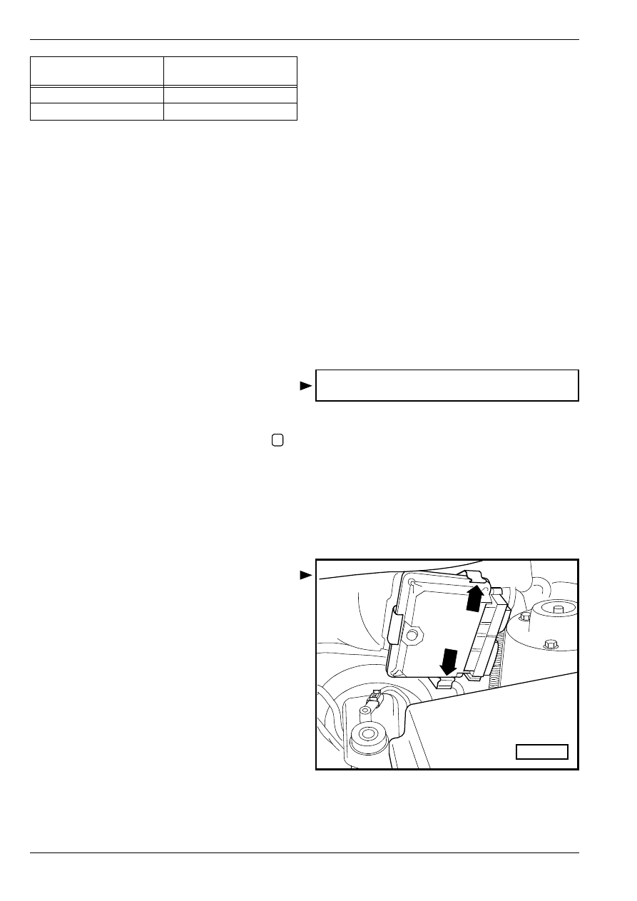
FABIA 2000
➤
1.9/96 TDI Engine, Fuel Injection
Engine control unit
Edition 09.04
S00.5328.01.20
23-5
page
2
23
If the specified values are not reached:
–
Test diesel direct injection system relay -J322-.
Replacing diesel direct injection system
control unit -J248-
Special tools, test and measuring equipment and
auxiliary items required
♦
Vehicle system tester -V.A.G 1552- with cable
-V.A.G 1551/3, 3A, 3B oder 3C-
Procedure
–
Connect vehicle system tester -V.A.G 1552-. Switch
ignition on and enter address word 01 „Engine elec-
tronics“
⇒
Chapter 01-1.
The vehicle system tester -V.A.G 1552- displays the con-
trol unit identification, e.g.:
–
Note Part No. of control unit and coding.
–
Enter function 06 „End output“ and confirm with
.
Removing
–
Switch off ignition.
–
Remove air filter
⇒
Chap. 23-1.
–
Release the connector catches and unplug the con-
nectors of the diesel direct injection control unit
- J248-.
–
Press off catch pegs -arrows- to the outside and pull
out the control unit to the side.
Installing
Installation undertaken in the reverse order.
After installing the diesel direct injection system control
unit -J248-, it is then necessary to carry out the following
steps:
–
Coding diesel direct injection system control unit
-J248-
⇒ 23-5
page 3.
–
Adapt the new diesel direct injection system control
unit -J248- to the immobiliser control unit
⇒
Electrical
System; Rep. Gr. 96.
–
For vehicles with cruise control system: Activate CCS
⇒ 23-5
page 4.
Test box -V.A.G 1598/
31-, bush
Specification
1, 2 + 4, 5
approx. battery voltage
37 + 4, 5
approx. battery voltage
038906019LA 1.9l R4 EDC G000SG 1576 ->
Coding 00102 WSC XXXXX
Q
S24-0373
FABIA 2000
➤
1.9/96 TDI Engine, Fuel Injection
Engine control unit
Edition 09.04
S00.5328.01.20
23-5
page
3
23
–
Interrogate fault memory of new engine control unit
and erase fault memory, rectify any faults present
⇒
Chap. 01-1.
–
Each time the fault memory is erased, it is then neces-
sary to re-generate the readiness code
⇒
Chapter 01-
3.
–
Perform a test drive.
Comply with the applicable safety instructions during the
test drive
⇒
Chap. 23-1.
–
Once again interrogate the fault memory of the diesel
direct injection system control unit - J248-.
Coding diesel direct injection system
control unit -J248-
If the code displayed does not match the vehicle or if the
diesel direct injection system control unit -J248- has been
replaced, it is then necessary to code the control unit as
follows.
Special tools, test and measuring equipment and
auxiliary items required
♦
Vehicle system tester -V.A.G 1552- with cable
-V.A.G 1551/3, 3A, 3B oder 3C-
Procedure
–
Connect vehicle system tester -V.A.G 1552-. Switch
ignition on and select address word 01 „Engine elec-
tronics“
⇒
Chap. 01-1.
–
Enter function 07 „Code control unit“.
Readout on display:
–
Enter code number by referring to table of codes and
confirm with
.
Table of codes:
The vehicle system tester -V.A.G 1552- displays the con-
trol unit identification, e.g.:
–
Enter function 06 „End output“ and confirm with
.
–
Switch ignition off and on again.
The entered coding is activated by switching the ignition
on and off again.
Note
Coding control unit
Enter code number xxxxx (0 -32767)
Q
Control unit identification
Variant
Code number
038 906 019 LA
with air conditioning
00102
without air conditioning
00105
038906019LA 1.9l R4 EDC G000SG 1567 ->
Coding 00102 WSC XXXXX
Q
Note
FABIA 2000
➤
1.9/96 TDI Engine, Fuel Injection
Engine control unit
Edition 09.04
S00.5328.01.20
23-5
page
4
23
Activating and deactivating cruise con-
trol system (CCS)
Special tools, test and measuring equipment and
auxiliary items required
♦
Vehicle system tester -V.A.G 1552- with cable
-V.A.G 1551/3, 3A, 3B oder 3C-
Test condition
•
No fault in fault memory, interrogating fault memory
⇒
Chap. 01-1
Procedure
–
Connect vehicle system tester -V.A.G 1552-. Switch
ignition on and select address word 01 „Engine elec-
tronics“
⇒
Chap. 01-1.
Read-out on display, e.g.:
If „G000SG“ is displayed, the cruise control system is ac-
tive
Readout on display:
If „000SG“ is displayed, the cruise control system is not
active
–
Press .
–
Select function 11 „login procedure“.
Readout on display:
–
Enter code number as stated in the table.
–
Confirm with
.
–
Select function 06 „End output“ and confirm with
.
After activating the cruise control system perform a test
drive as a functional test.
038906019LA 1.9l R4 EDC G000SG 1576 ->
Coding 00102 WSC XXXXX
038906019LA 1.9l R4 EDC 000SG 1576 ->
Coding 00102 WSC XXXXX
Login procedure
Enter code number XXXXX
Code number
Cruise control system (CCS)
11463
Activate CCS
16167
Deactivate CCS
Q
Q

FABIA 2000
➤
1.9/96 TDI Engine, Fuel Injection
Testing auxiliary signals
Edition 07.03
S00.5328.00.20
23-6
page
1
23
23-6
Testing auxiliary signals
⇒
1.9/74 TDI Engine, Fuel Injection; Rep. Gr. 23

FABIA 2000
➤
1.9/96 TDI Engine, Fuel Injection
Testing auxiliary signals
Edition 07.03
S00.5328.00.20
23-6
page
2
23

FABIA 2000
➤
1.9/96 TDI Engine, Fuel Injection
Testing preheating system
Edition 07.03
S00.5328.00.20
28-1
page
1
28
28-1
Testing preheating sys-
tem
⇒
1.9/74 TDI Engine, Fuel Injection; Rep. Gr. 28
28 – Glow Plug System

FABIA 2000
➤
1.9/96 TDI Engine, Fuel Injection
Testing preheating system
Edition 07.03
S00.5328.00.20
28-1
page
2
28
Wyszukiwarka
Podobne podstrony:
Gasoline Fuel Injection System K Jetronic
Fuel Injection Systems Bosch Cis
Mechanics of a Diesel Fuel Injection System
SMeyer CA2067735A1 Water Fuel Injection System
How to configure fuel injectors on the pre CAN Duratorq HPCR
Self Study Programme 351 Common rail fuel injection system fitted in the 3 0l V6 TDI engine
LR Fuel InjectionSystems
Bosch K Jetronic And Ke Jetronic Mechanical Fuel Injection Haynes
Fuel injection
Bmw e12 5 Series L Jetronic Fuel Injection Systems
Audi A8 4,2 fuel injection engine ENG
BOSCH HDI EDC15C2 injection system (2)
biogas as vehicle fuel id 87120 Nieznany
4 Fuel and Lubrication System
08 fuel system
05 Fuel System
więcej podobnych podstron