Vehicle Diagnosis System
Group Tester One (GT1)
Working with the GT1 — Version 2.1

BMW Group Tester One, Working with the GT1
Version 2.1, December 2003

Contents
BMW Group Tester One, Working with the GT1
Version 2.1, December 2003
I-1
Contents
General Information....................................... 1-1
Safety Instructions .................................................1-1
Target Group of This Manual .................................1-2
Installing Software ........................................ 2-1
Enclosed or Delivered CDs ....................................2-1
Starting Operating Unit ..........................................2-1
Starting installation ................................................2-2
Setting Up System with Installation CD .................2-2
Installing Base CD..................................................2-3
Installing Program CD ............................................2-7
Only or first Program CD........................................2-8
Follow-Up CD ........................................................2-9
Separate CIP CD..................................................2-10
Installing TIS ........................................................2-10
Network Configuration .................................. 3-1
Introduction............................................................3-1
GT1 Network Configuration ...................................3-1
Connection Types, Diagnostic Head –
Operating Unit........................................................3-2
Completion of Commissioning ...............................3-2
Operation....................................................... 4-1
Display Elements ...................................................4-1
Changing Applications ...........................................4-5
Diagnosis ...............................................................4-5
Measurement System ............................................4-6
Coding/Programming.............................................4-8
Administration ........................................................4-9
Technical Information System (TIS)......................4-10
Help .....................................................................4-10
Measuring Cable..................................................4-12
Battery .................................................................4-13
Switching Off .......................................................4-13
Shutting Down the System...................................4-13
Forced Switch-off ................................................4-14
Troubleshooting............................................. 5-1
Faults: Symptoms/Causes .....................................5-1
Self-test .................................................................5-1
5.1.2
Control Panel .........................................................5-2

Contents
BMW Group Tester One, Working with the GT1
Version 2.1, December 2003
I-2
Touch Screen.........................................................5-3
Plug-in Connections .............................................5-4
Battery ...................................................................5-4
Printer ....................................................................5-5
Docking Station......................................................5-6
Diagnostic Head ....................................................5-7
Accessories ...........................................................5-8
Fault Codes............................................................5-9
Forms and Addresses .................................... 6-1
Online Registration ................................................6-1
Forms for Registration / Fault Reports...................6-1
Service Addresses .................................................6-2
Terms and Abbreviations ............................... 7-1
Definitions ..............................................................7-1
7.2
List of Abbreviations ..............................................7-4

General Information
BMW Group Tester One, Working with the GT1
Version 2.1, December 2003
1-1
1
General Information
The "Working with the GT1" manual contains all of the infor-
mation required for software installation, network administration
and connection of the diagnostic head for use in accordance
with the intended purpose of the vehicle diagnosis system Group
Tester One, hereinafter referred to as GT1.
It supplements the "Components and Functions" manual, in
which you will find all the information regarding the hardware
components and first-time commissioning.
Both manuals ("Components and Functions", "Working with
the GT1") are to view as a whole. They address technically qual-
ified personnel who have relevant knowledge in the field of vehi-
cle diagnosis and measuring systems.
Knowledge of and technically flawless implementation of the
safety instructions and warnings contained in both manuals are
a prerequisite for safe commissioning and for safety during op-
eration and maintenance of the GT1.
So that the manuals remain easy to understand, they do not con-
tain details of all versions of the described operating modes
1
and are unable to take account of every conceivable case of
commissioning, operation or maintenance and service.
It can also be the case that the content of the screen displays
shown deviates slightly from what is shown on the operating
unit.
1.1
Safety Instructions
Read and comply with the safety instructions for the GT1. The
general safety instructions can be found after the table of con-
tents of the "Components and Functions" manual; specific
safety instructions can be found at the relevant points in both
manuals.
1. The glossary arrow indicates that the marked expression is explained in
chapter 8.

General Information
BMW Group Tester One, Working with the GT1
Version 2.1, December 2003
1-2
1.2
Target Group of This Manual
This manual is addressed to the users and/or system administra-
tors who carry out the initial installation, implement version
changes on the GT1 or adapt it to an existing dealership net-
work. It is intended to help you to enable smooth and reliable op-
eration of the Group Tester One in your workshop and network
environment.
Installing Software
BMW Group Tester One, Working with the GT1
Version 2.1, December 2003
2-1
2
Installing Software
2.1
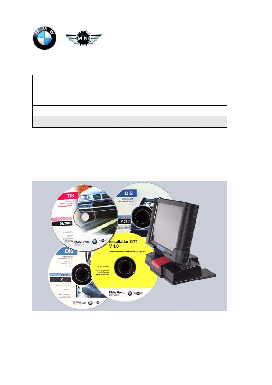
Enclosed or Delivered CDs
A number of CD-ROMs, which you require for the initial installa-
tion, are shipped with the GT1.
The installation is always performed in the order Installation CD,
Base CD, Program CD.
Note
Only run the installation in this order. Future versions of the Pro-
gram CD might consist of a number of media. These CDs are
clearly labeled as initial or follow-on CD. A CD delivery can also
contain special Program CDs, e.g. CIP CD.
When handling CDs, observe the instructions of operation of the
DVD drive (see DVD inclinations in the "Components and
Functions" manual).
2.2
Starting Operating Unit
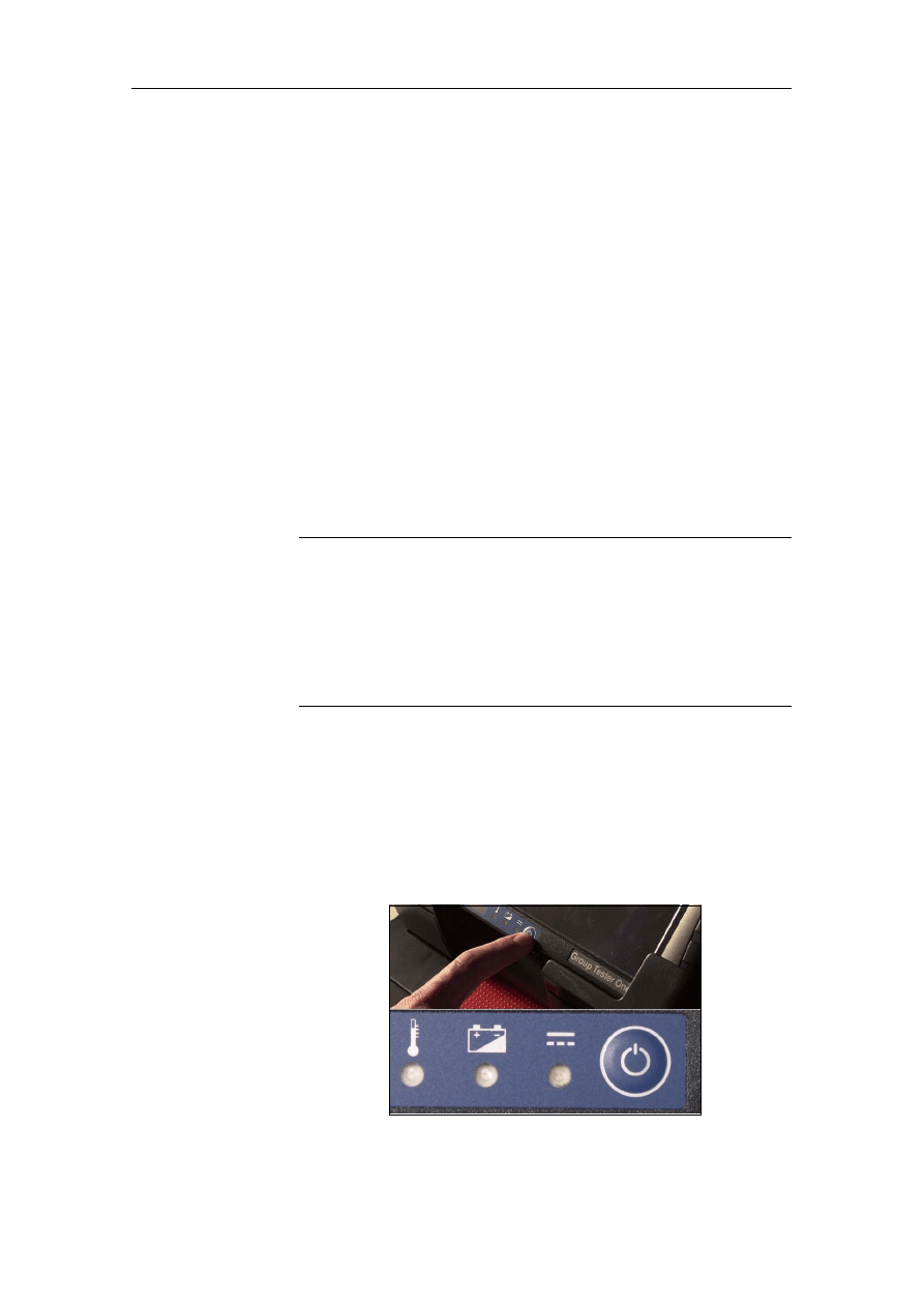
Start the operating unit in the stationary mode as follows:
set the operating unit reception point of the docking station to
the DVD inclination. Switch the operating unit on by pressing the
on/off button on the front.
Fig. 2-1 Position of the on/off button on the block of controls
Installation CD
yellow cover with the lettering "Installation
GT1"
Base CD
red lettering "GT1 Base"
Program CD
black lettering "GT1 Programs"
CIP CD
Program CD for the applications Coding,
Individualization, Programming as of E65
(as of CD 30)
Installing Software
BMW Group Tester One, Working with the GT1
Version 2.1, December 2003
2-2
2.3
Starting installation
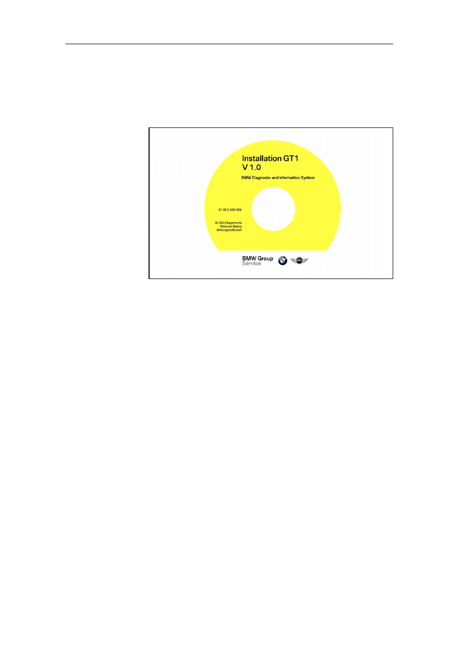
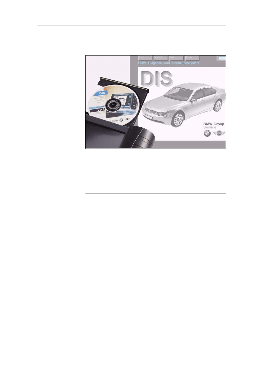
2.3.1
Setting Up System with Installation CD
Fig. 2-2
Example: CD installation GT1
1. Open the DVD drive by pressing its eject button.
2. If present, remove the transportation lock.
3. Insert the yellow CD labeled "Installation GT1". Ensure that
you comply with the instructions for operation of the DVD
drive.
4. Close the drive.
5. Press the on/off button and hold it down for 5 seconds so that
the operating unit switches off again.
6. Press the on/off button again so that the operating unit
switches itself on again. The hard disk of the GT1 is now pre-
pared for installation of the operating system.
While the installation is running, various messages appear on the
touch screen; you can ignore these.
The installation is complete when the operating unit issues the
message:
Please insert CD "GT1 Base", switch off and on the com-
puter

Installing Software
BMW Group Tester One, Working with the GT1
Version 2.1, December 2003
2-3
2.3.2
Installing Base CD
The next step is to install the Base CD as follows:
1. Open the DVD drive again and take out the "Installation GT1"
CD. Insert the Base CD labeled "GT1 Base".
2. Close the drive.
3. Press the on/off button and hold it down for 5 seconds so that
the operating unit switches off again.
Note
If you have inadvertently inserted the wrong CD, the following
message appears on the touch screen:
This is the wrong installation CD!
Please replace current CD by the basic installation CD!
Switch off and on again the system!
The installation of the operating system is continued now. It
takes approx. 20 minutes. While the installation is running, vari-
ous messages appear on the touch screen; you can ignore
these. The installation is complete when the operating unit is-
sues the message:
End of cdinstall !!!
Please remove the CD !!!!!!!!!
and switch the system off and on again to continue
system halted
4. Open the DVD drive again and take out the Base CD.
Press the on/off button and hold it down for 5 seconds so that
the operating unit switches off again.
5. Press the on/off button again so that the operating unit
switches itself on again. Powering up is completed when the
"Language selection/Dealer identification" window appears
on the touch screen.
Installing Software
BMW Group Tester One, Working with the GT1
Version 2.1, December 2003
2-4
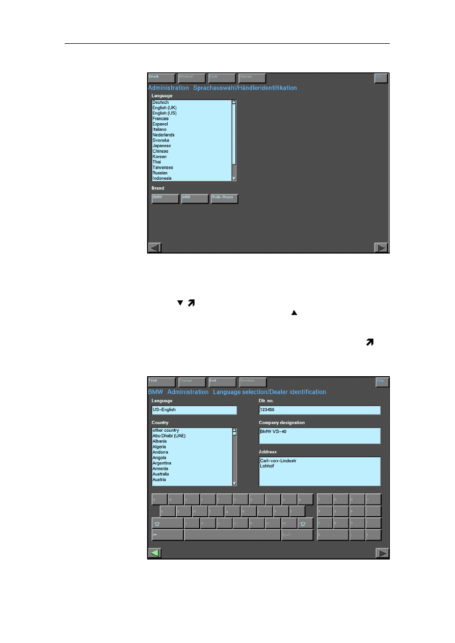
Fig. 2-3
Language selection/Dealer identification (prior to language selec-
tion)
Setting the
language
You can also scroll the list line by line. If you click on the "Down
arrow" ( ) button on the scrollbar, the list moves one line up-
wards; if you click on the "Up arrow" ( ), it scrolls downwards
again by one line.
Click on your language in the "Language" list. The selected line
is now inverted, i.e. the text is highlighted and has a dark se-
lection bar. The screen display changes to the following window
(see fig. 2-4):
Fig. 2-4
Language selection/Dealer identification (after language selection,
with sample input)

Installing Software
BMW Group Tester One, Working with the GT1
Version 2.1, December 2003
2-5
Note
If you have inadvertently set the wrong language, you should
change the selection now before you enter your dealer identifi-
cation. If you change the language later, any data entered up to
that point is lost!
You can return to the language input by pressing the "Back"
button at the bottom left of the touch screen. It is identified by
a green arrow pointing to the left.
Setting the
country
Select the country in which you are operating the GT1 in the
"Country" selection list.
Entering the
dealer
identification
To the right of the selection list, you will now find the input fields
for the dealer identification and in the lower section of the win-
dow a virtual keyboard. Use this to enter your dealer identifi-
cation, consisting of three parts: the dealer number ("Dlr. no."),
the company designation and the company address. The touch
screen provides a separate entry field for each part.
1. Press the "Dlr. no." field.
2. Press the virtual keys to enter your dealer number. The keys
react to contact with the touch screen in the same way as a
normal computer keyboard.
Note
You can use the "Backspace" key marked with an arrow pointing
to the left to delete input errors in order to continue with im-
proved inputs. Bear in mind that the keyboard input is reset to
lower case following entry of an upper case letter via the previ-
ously touched "Shift" key.
3. Click in the "Company designation" field and enter your com-
pany name in the same way. The "Return/Enter" key, marked
by an arrow pointing down towards the left, changes to the
next line.
4. Click in the "Address" field and enter your address.
Installing Software
BMW Group Tester One, Working with the GT1
Version 2.1, December 2003
2-6
Important
Please ensure that the settings of the dealer number and host
name are correct (for host name, see Network Administration)!
In cases of doubt, please obtain this information from your local
service provider. The service provider knows the data and can
issue it!
The dealer number match that in the DISPlus, if this device is de-
ployed at your dealership!
Make sure that you check your input! After saving, you can only
change the dealer identification by re-installing the Base CD!
5. At the top border of the touch screen, press the "End" button.
A small pull-down menu containing a number of buttons
opens up.
6. Press the "End" button. There is now a save query in which
you can still cancel the saving of the dealer identification if
necessary.
7. If you confirm with "Yes", the operating unit saves your dealer
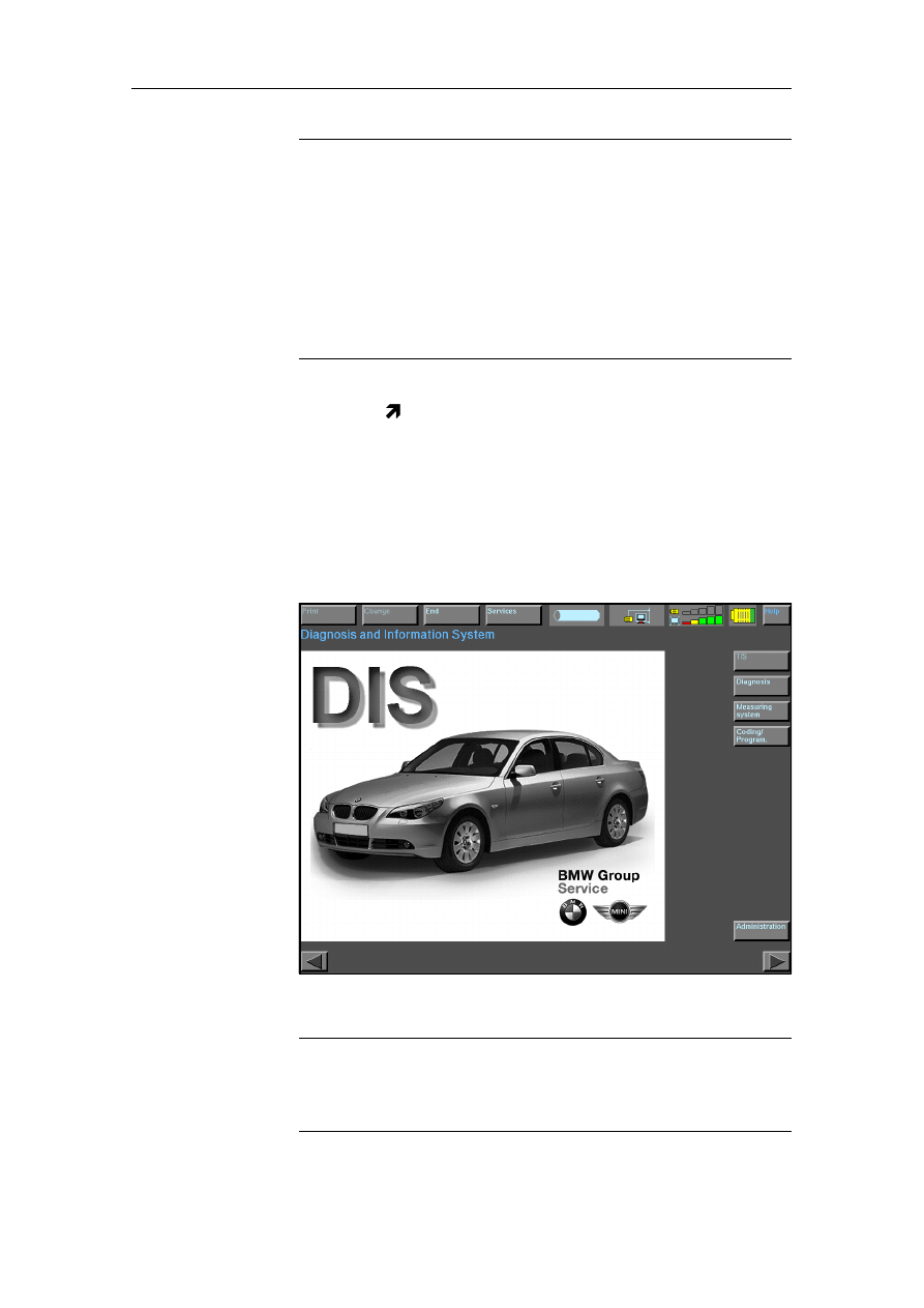
identification. The GT1 reboots. The so-called start window
then appears, and it looks the same as or similar to the one
shown here.
Fig. 2-5
Start window (example)
Note
The buttons "TIS", "Diagnosis", "Measuring system" and "Cod-
ing/Program." are only enabled after the diagnostic programs
have been loaded from the Program CD.
Installing Software
BMW Group Tester One, Working with the GT1
Version 2.1, December 2003
2-7
2.3.3
Installing Program CD
Fig. 2-6
Preparing installation of the Program CD
Check the "CD drive allocation" field. If the "GT1 Programs" CD
is already in the DVD drive, the output "CD 1 active" and the title
of the CD must be displayed in the in the "CD drive allocation"
window.
Note
If the drive CD 1 is shown as "not active", it can be assumed that
the "GT1 Programs" CD is no longer in the DVD drive. Its eject
button is enabled; the "Activate CD", "Deactivate CD" and
"Change CD" buttons are disabled. Insert the "GT1 Programs"
CD and close the DVD drive.
In the "CD drive allocation" window, press the line "CD drive 1".
The line is inverted and the "Activate CD" button is enabled.
Press the "Activate CD" button. The title of the CD appears in the
"CD drive allocation" window; the "Activate CD" button is dis-
abled; the eject button of the CD-drive is disabled.
Installing Software
BMW Group Tester One, Working with the GT1
Version 2.1, December 2003
2-8
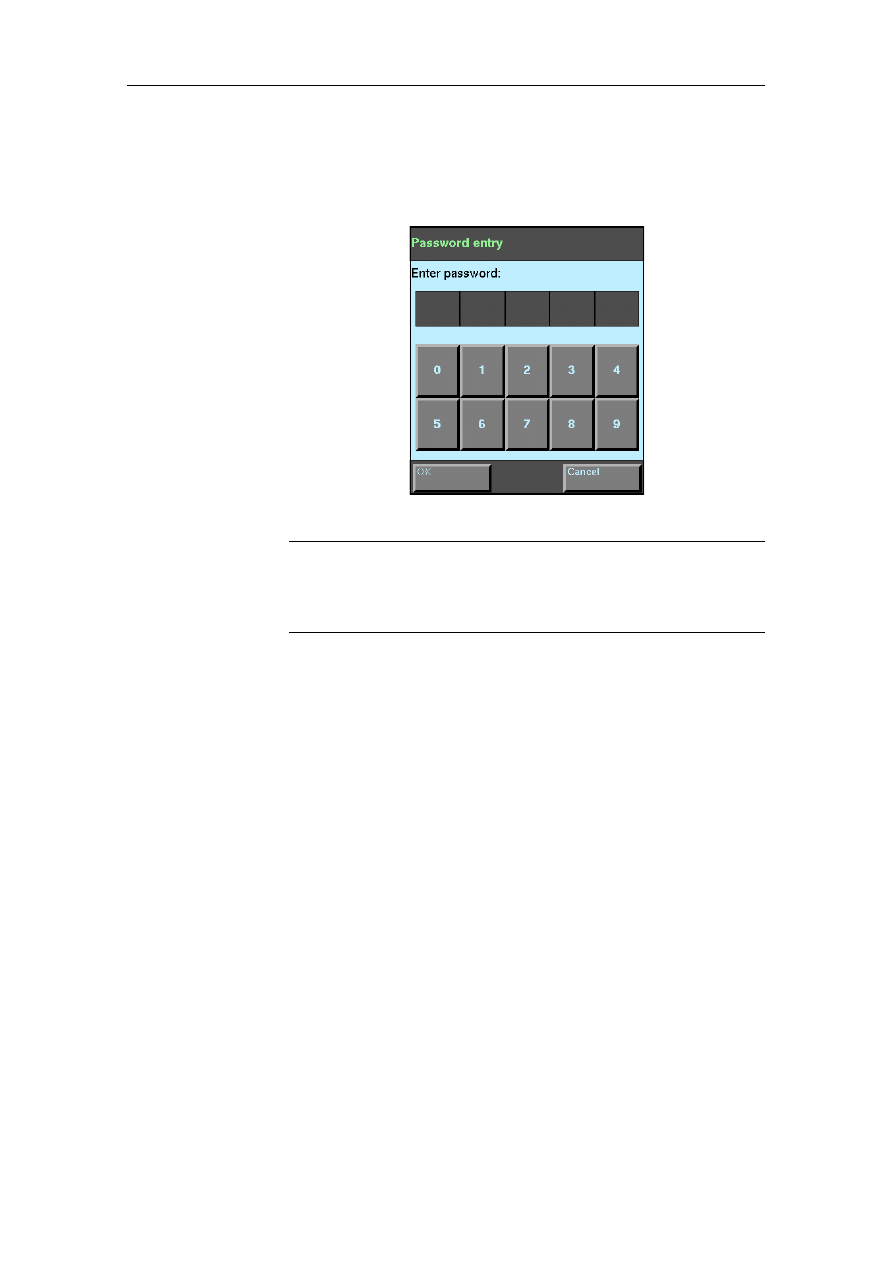
2.3.4
Only or first Program CD
In the "DIS" column, press the "Installation" button. The window
shown below appears:
Fig. 2-7 Password entry
Note
Makes sure that you press the right button. The "TIS" column
also contains a button of the same name; at this stage, however,
it would produce an error message!
1. Use the displayed virtual keypad to enter your password.
This corresponds to the last five digits of your dealer number.
2. Then confirm the input with the "OK" button. A confirmation
prompt now appears on the touch screen, allowing you to
check once again whether the correct program CD has been
inserted.
3. Confirm with "OK". The installation of the diagnostic program
now begins. This can take up to 40 minutes. During this time,
you will see a window on the touch screen which gradually
fills up with large "XXX". When the installation is complete,
the operating unit issues a message that you can confirm
with the "OK" button. The message disappears and the "Ad-
ministration" window is displayed once again.

Installing Software
BMW Group Tester One, Working with the GT1
Version 2.1, December 2003
2-9
2.3.5
Follow-Up CD
If you have received more than one Program CD, the follow-up
CD for the Program CD (designation CD 2/2) must be inserted in
accordance with the instructions on the touch screen.
Note
The installation of a follow-up CD is handled as if you are per-
forming a separate installation of a Program CD. A window on
the touch screen informs you that a follow-up CD has to be in-
stalled and you have to confirm this message with "OK".
1. In the "CD drive allocation" window, press the line "CD
drive 1".
The line is inverted and the "Deactivate CD" button is en-
abled.
Press the "Deactivate CD" button. The text "not active" ap-
pears in the "CD drive allocation" window. The DVD drive is
enabled.
2. Remove the CD labeled CD1 from the DVD drive and insert
the CD labeled CD2.
Close the DVD drive.
In the "CD drive allocation" window, press the line "CD
drive 1".
The line is inverted and the "Activate CD" button is enabled.
Press the "Activate CD" button. The title of the CD appears in
the "CD drive allocation" window; the "Activate CD" button is
disabled; the eject button of the CD-drive is disabled.
Proceed with the installation as described at 2.5.1.
Installing Software
BMW Group Tester One, Working with the GT1
Version 2.1, December 2003
2-10
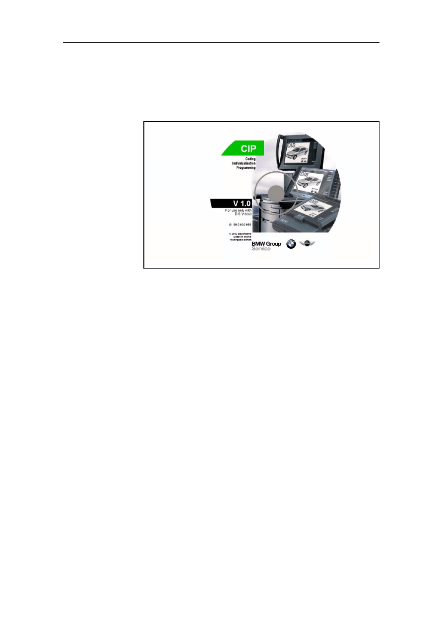
2.3.6
Separate CIP CD
From CD 30, the CIP CD is supplied as a separate CD. Install this
in the same way as a program update CD by using the "Update"
button.
Fig. 2-8
Example: label separate Program CD CIP
2.4
Installing TIS
In addition to the DIS base system and the DIS programs, the
Technical Information System (TIS) is also available to you. It is
supplied on a separate Installation CD. Install the "TIS" CD as
follows:
1. In the "CD drive allocation" window, press the line "CD
drive 1". The "Deactivate CD" and "Change CD" buttons are
enabled.
2. Press the "Change CD" button. The eject button of the DVD
drive is enabled. A message appears asking you to insert a
new CD.
3. Remove the Program CD and insert the "TIS" CD in the DVD
drive. Be sure to observe the instructions for operation of the
DVD drive (see "Components and Functions" manual).
Confirm the prompt by pressing the "OK" button.
4. In the "TIS" column, press the "Installation" button. Now se-
lect installation on hard disk in the dialog that appears and
confirm with "OK". The installation now runs automatically. It
can take up to 2 hours. When the installation is complete, the
operating unit issues a message that you can confirm with
the "OK" button. The message disappears and the "Adminis-
tration" window is displayed once again.

Installing Software
BMW Group Tester One, Working with the GT1
Version 2.1, December 2003
2-11
Completing the
installation
When all the installations have been completed, conclude the
operation as follows:
1. In the "CD drive allocation" window, press the line "CD
drive 1". The line is inverted and the "Deactivate CD" and
"Change CD" are enabled.
2. Press the "Deactivate CD" button. The eject button of the
DVD drive is enabled.
3. Remove the CD from the DVD drive.
The next step is to configure the network settings of the
GT1.

Installing Software
BMW Group Tester One, Working with the GT1
Version 2.1, December 2003
2-12
Network Configuration
BMW Group Tester One, Working with the GT1
Version 2.1, December 2003
3-1
3
Network Configuration
3.1
Introduction
The features of the Group Tester One measuring and diagnosis
system include not only its mobility and wide variety of functions,
but also network capability, providing a large number of commu-
nication options.
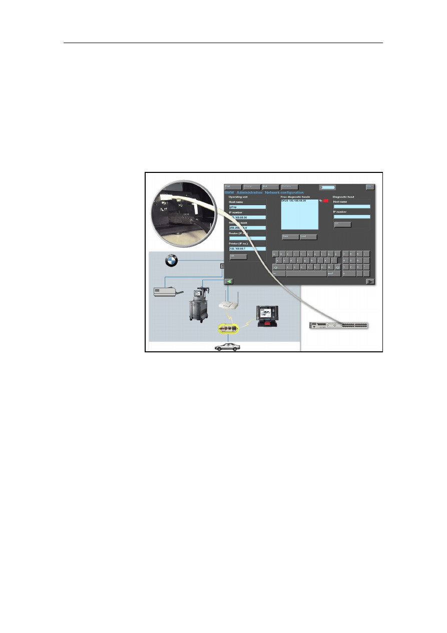
Fig. 3-1
GT1 network technology
3.2
GT1 Network Configuration
In order to be able to use these possibilities and to guarantee commu-
nication of your GT1 with the various participants in the network, e.g.
the diagnostic head, the OPPS or a network printer, it must be possible
to uniquely identify the devices in the network.
As expansions have meanwhile been introduced in several perfor-
mance levels for the use of the diagnosis and programming systems
DISPlus, GT1, SSS, OPPS/OPS and DH in a network, these functions
and services are summarized in a separate set of documentation.
Please read through this information provided on the documentation
CD in the description "
Full Network Functionality" very carefully be-
fore you integrate the GT1 in the network or produce a connection to a
DH/OPPS/OPS.

Network Configuration
BMW Group Tester One, Working with the GT1
Version 2.1, December 2003
3-2
Note
During all configuration measures, observe the current information on
the
Full Network Functionality included on the documentation CD as
separate instructions.
3.3
Connection Types, Diagnostic Head –
Operating Unit
From CD 34 there are additional options for connecting the diag-
nostic head to the operating unit or the docking station.
• LAN cable – direct connection (peer-to-peer)
• USB LAN cable – direct connection
• Radio direct connection
• LAN cable – connection via switch
• USB LAN cable – connection via switch
• LAN cable – radio connection via switch and access
point
Note
During all configuration measures, observe the current information on
the
Full Network Functionality included on the documentation CD as
separate instructions.
3.4
Completion of Commissioning
When you complete the commissioning of the GT1, press the
"End" button in the "Services" bar and then the "Exit" button that
appears.
The start window is displayed again. In a manner of speaking,
this is the control center. From here, you can call up all the op-
erating modes of the GT1,e.g.:
• Diagnosis
• Measurement system
• Coding / Programming
• Administration
• TIS
• Help
Details of the operating modes can be found in section 4.2.
Operation
BMW Group Tester One, Working with the GT1
Version 2.1, December 2003
4-1
4
Operation
This chapter describes the general use of the operating unit and
calling up the individual operating modes. A detailed descrip-
tion of the operating modes and their practical application can
be found in the corresponding documentation.
4.1
Display Elements
Simple Operation
The GT1 is operated via the touch screen. Displays with infor-
mation, queries, documents and buttons that trigger functions
and actions appear on the touch screen.
Fig. 4-1
Display elements of a window (example)
1 Title bar
2 Button
3 " Services" bar
4 Workspace
5
Selection bar
6 Dialog box
7 Scrollbar
8
Navigation bar
2
1
3
4
5
6
7
8
Operation
BMW Group Tester One, Working with the GT1
Version 2.1, December 2003
4-2
Window
The graphic displays on the touch screen are referred to as
windows or also masks. They display all the information and
control functions.
Windows usually have the same structure: bars of buttons at the
top and bottom borders for control in the individual operating
modes; the middle (and largest) section is the workspace where
you can make selections or enter data. Smaller dialog boxes that
contain special messages or prompts can be superimposed on
the main window.
Title bar (1)
The title bar indicates which operating mode and in which win-
dow you are currently working.
Button (2)
In each window, different buttons appear, and you can use these
to select the various functions.
You can see from the color of the button whether it is enabled. If
it is dark and the screen surface appears concave (relief), it has
been pressed and/or enabled.
"Services"
button (3)
The "Services" bar contains a number of buttons which, when
pressed, each open up a pull-down menu containing other
buttons. On the right border of this line is the "Help" button (see
Workspace (4)
The workspace comprises the largest section of the user inter-
face. Depending on the operating mode, the display changes.
Note
The content of the workspace illustrated in this manual is intend-
ed as an example and it is not necessarily identical to the content
of your touch screen.
In the start window, the start graphic (splash screen) appears in-
stead of the workspace; to the right is the "Program selection",
whose buttons you can use to call up the individual operating
modes.
Pressed button
You have pressed this button
or it is already enabled. As
soon as you are no longer
touching the touch screen, the
desired command is run.
Non-pressed button
You can see this button on the
touch screen, but you have not
pressed it.

Operation
BMW Group Tester One, Working with the GT1
Version 2.1, December 2003
4-3
Selection bar (5)
If you select a line in a field of the workspace, this is highlighted
by a dark selection bar (inverted). The selected section of text is
made bright. In most cases, the next window opens as soon as
you let go of the touch screen. If this does not happen, the oper-
ating unit might be offering you the possibility to select a number
of lines. Select all the lines you require. To then enter the next
window, press the "Next" button in the navigation bar.
Dialog box (6)
A dialog box is a small window that is superimposed on the main
window. Here, the operating unit displays supplementary infor-
mation, operating options and error messages so that you are
able to perform the next steps in the selected program.
Note
As long as a dialog box is open, you cannot press the buttons of
the main window. First, you must press a button in the dialog box
to close it.
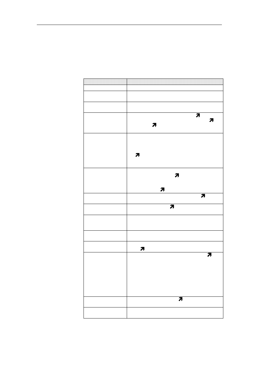
The following buttons, among others, can appear in dialog
boxes:
Table 4-1
Buttons of the dialog box (selection)
Help also appears in a dialog box. For operation of the online
Help, see Section 4.8.
Scrollbar (7)
If it is not possible for the entire text to be displayed in a window,
a scroll bar appears on its right side. This consists of a slider and
two arrows. The length of the slider shows you whether a small
or large document is involved. The smaller the slider, the larger
the amount of the document that has not yet been displayed.
To be able to read the text, touch the slider and move it upwards
or downwards. This makes the desired text visible. You can also
scroll the text line by line. If you click on the "down arrow" ( )
button on the scrollbar, the text moves one line upwards; if you
click on the "up arrow" ( ), it scrolls downwards again by one
line.
Button
Meaning
Cancel
You cancel an operation and are returned to the
previous window or box.
Exit
You terminate all operating modes and are re-
turned to the start window.
OK
You use "OK" to confirm the procedure or a dialog.
Close
The dialog window is closed.
Overview
A selection list is displayed, where you can select
the desired text or operation.
Operation
BMW Group Tester One, Working with the GT1
Version 2.1, December 2003
4-4
Navigation bar (8) The navigation bar is located in the lower section of the window.
You can use the buttons in this bar to call up navigation func-
tions. The navigation bar provides space for up to nine different
buttons. The number actually displayed depends on the type of
window and its current mode. You can press the desired button
so that the GT1 runs the corresponding command.
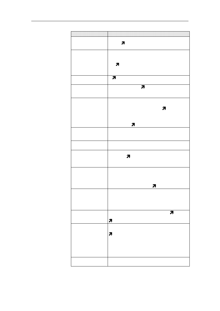
The navigation bar contains the following basic functions; these
are supplemented by other functions in the individual operating
modes:
Table 4-2
Some Functions of the Navigation Bar
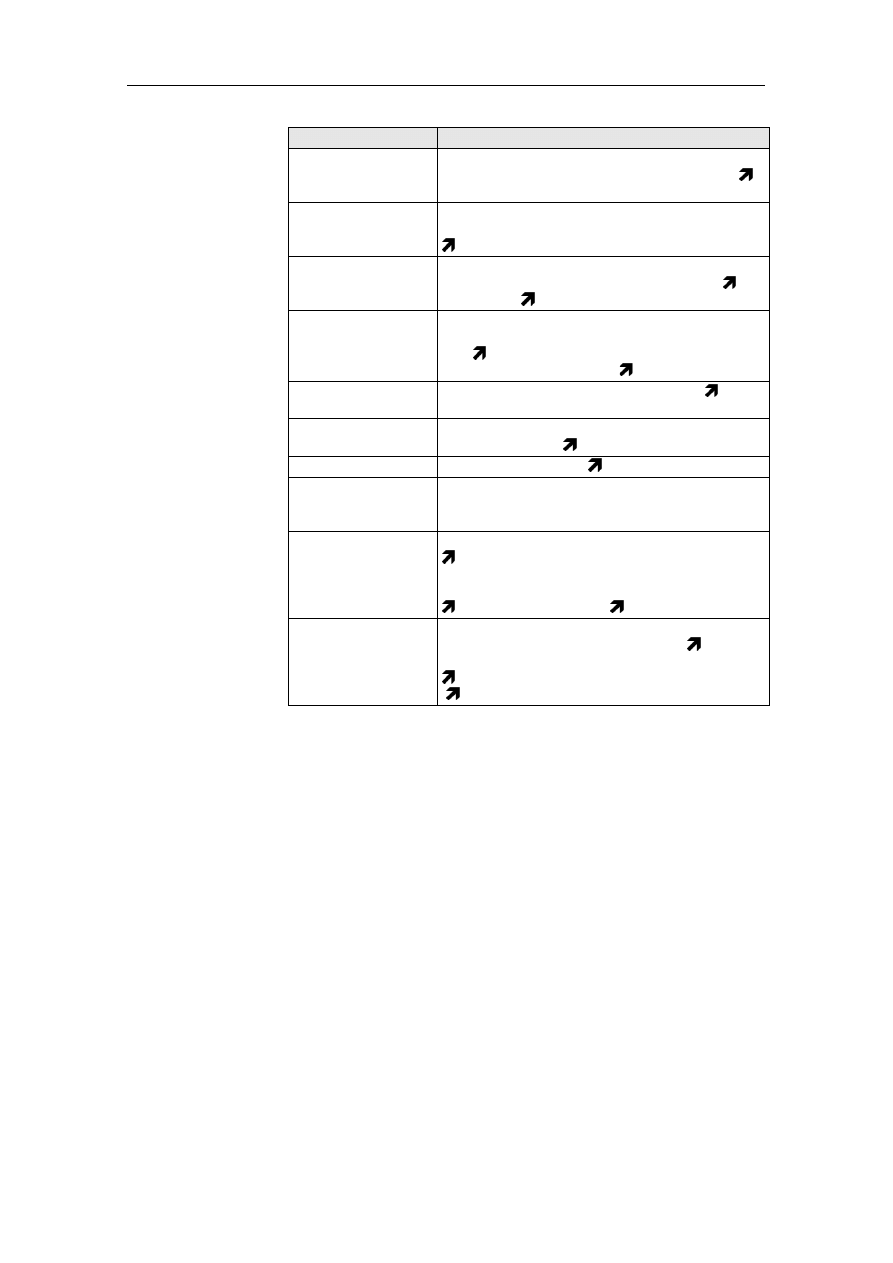
The cursor follows your input on the touch screen and always in-
dicates the position you last pressed. Depending on the current
function, it assumes various shapes.
Cursor
Table 4-3
Shapes of the Cursor
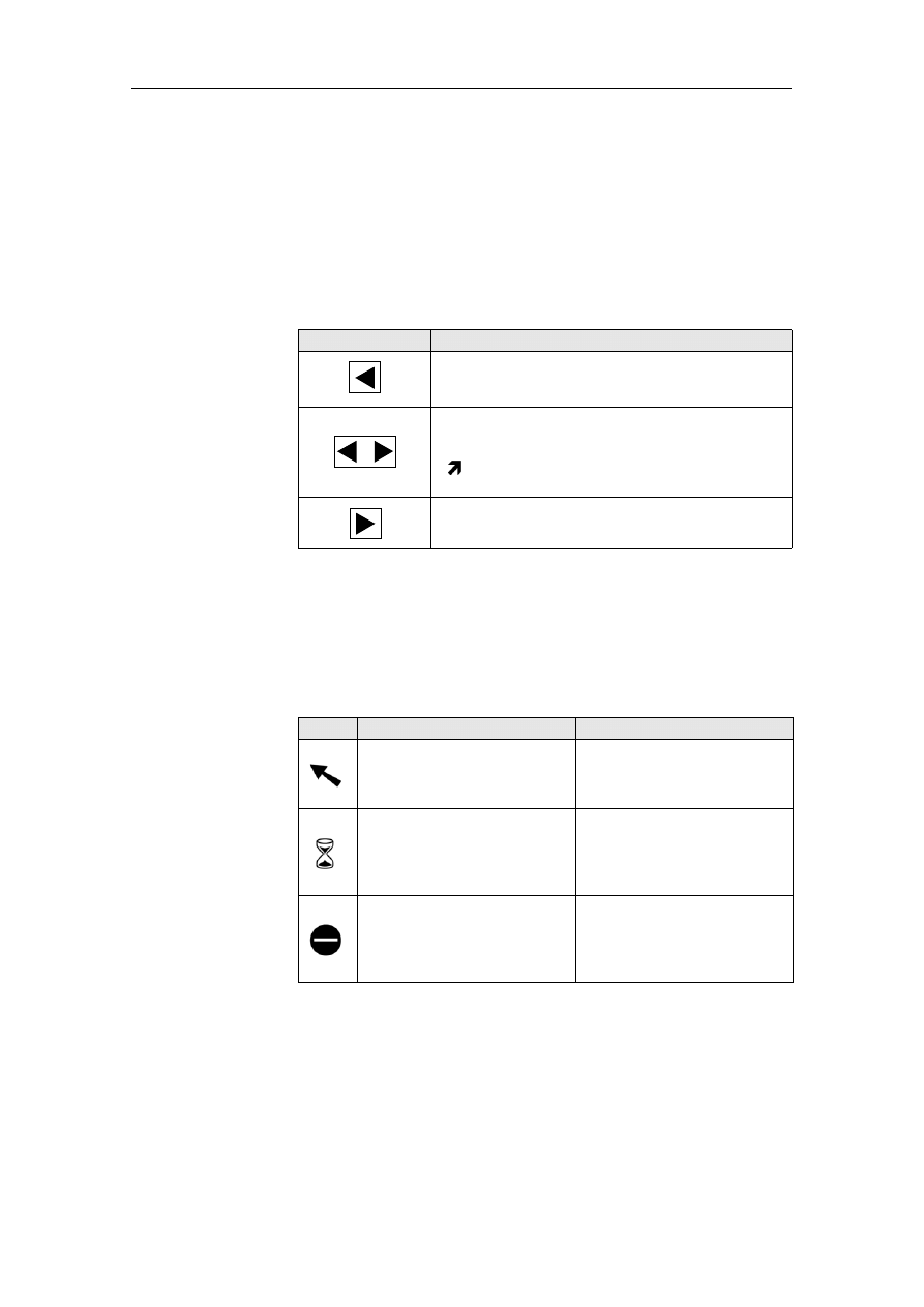
Button
Function
You can use the "Back" button to cancel or termi-
nate a function that is running or to return to the
previous window.
You can use the "Go to" button to return to win-
dows you have already been through so that you
can make new input there. If you press this button,
a
pull-up menu appears with a list of the win-
dows you worked in previously.
You use the "Next" button to accept the choice
made and to move to the next window.
Shape
Function
Note
The "arrow" is the shape of
the cursor you use to select
functions or buttons.
The "hourglass" appears
when the GT1 is processing
your input.
During this display, no other
entry can be made. Wait until
the cursor returns to the arrow
shape.
If the cursor assumes the
shape of a "no entry sign", you
cannot enter anything at this
position on the touch screen.
Move the cursor back to a po-
sition where an entry is possi-
ble. There, it assumes the
shape of an arrow again.
Operation
BMW Group Tester One, Working with the GT1
Version 2.1, December 2003
4-5
4.2
Changing Applications
The individual operating modes are called up using the buttons
on the right border of the start window. From one operating
mode, you can normally use the buttons of the navigation bar,
the "Services" button or the "Change" button to switch to other
operating modes and return to the original operating mode.
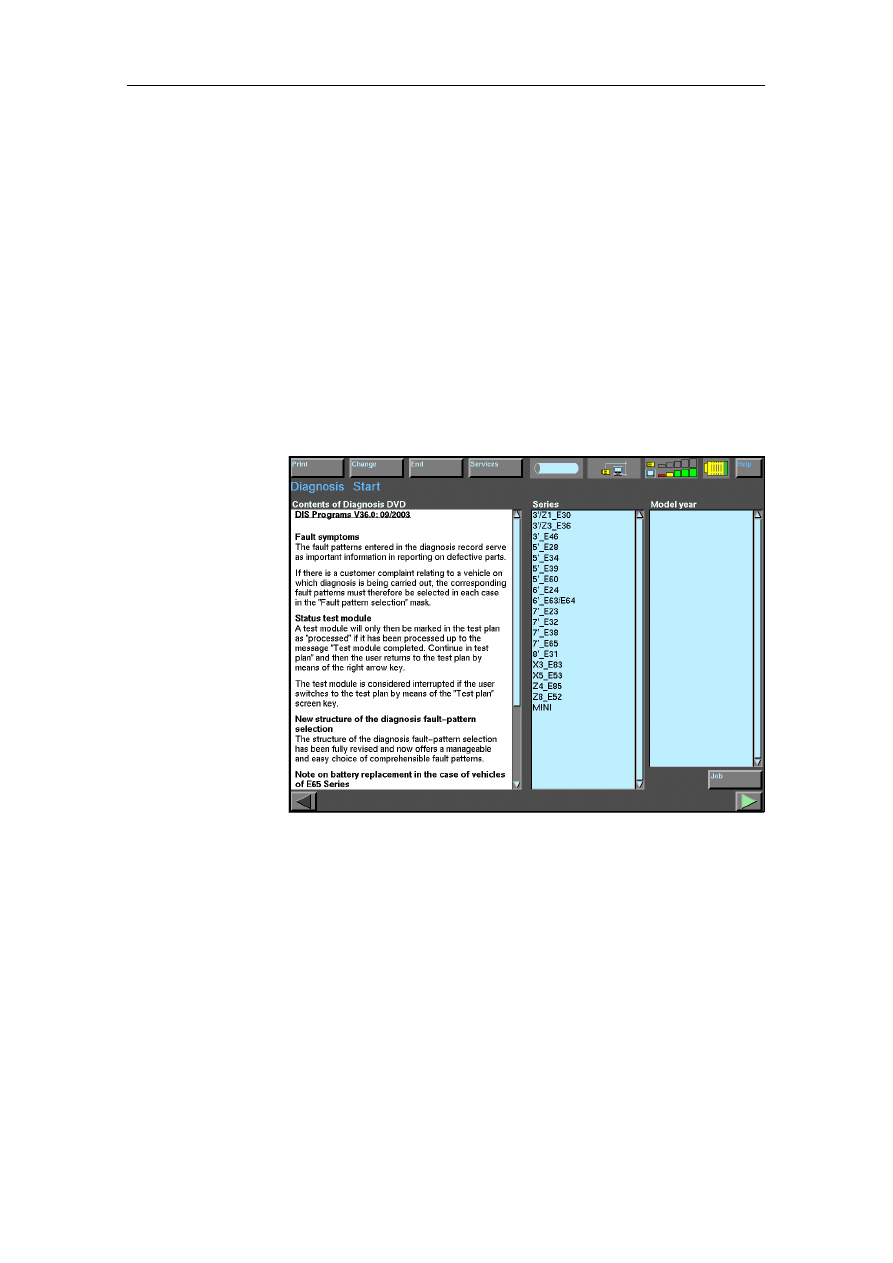
4.3
Diagnosis
First, ensure that there is a diagnosis connection to the vehicle.
The ignition lock must be in position 2 (ignition on); the system
voltage must be at least 9 Volts. If you now press the "Diagnosis"
button in the start window, the following window is displayed:
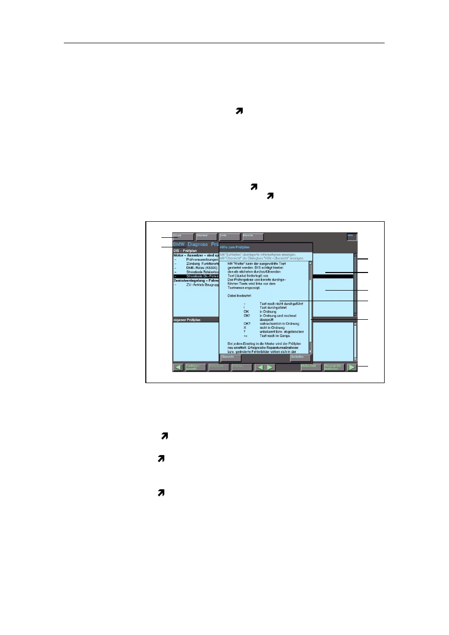
Fig. 4-2
Diagnosis Start (Example)
In the "Diagnosis" operating mode, you can reach various strat-
egies for troubleshooting. These can be used individually or
combined and can be defined as follows:
1. Troubleshooting on the basis of fault codes read out of con-
trol units
2. Troubleshooting on the basis of fault symptoms reported by
the vehicle owner, filtered and entered by you
3. Troubleshooting on the basis of your own considerations
(Expert mode) and choice of the suspicious component
group.
Operation
BMW Group Tester One, Working with the GT1
Version 2.1, December 2003
4-6
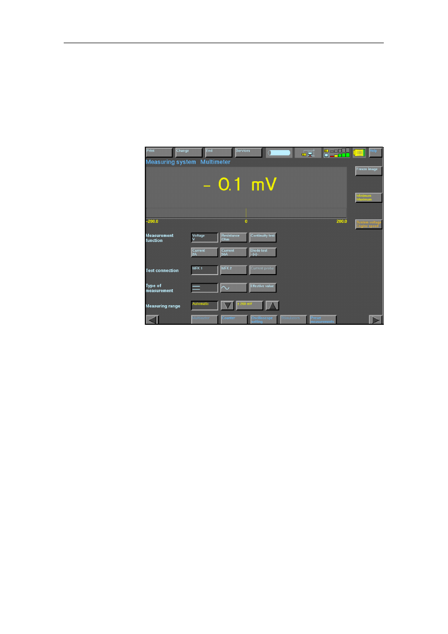
4.4
Measurement System
If you press the "Measurement system" button in the start
window, the "Multimeter" window is displayed as standard
(Fig. 6-3). Using the navigation bar, you can switch to the tech-
nical measuring functions "Counter", "Oscilloscope setting" and
"Preset measurements".
Fig. 4-3
Measurement System Multimeter
Multimeter
In the "Multimeter" window, you can use the multimeter of the
GT1 as a free measuring instrument. You can set the following
parameters manually:
• Measurement function (e.g. voltage or current)
• Measuring connection (e.g. multifunction cable 1)
• Measurement type (DC voltage, AC voltage)
• Measuring range (corresponding to the signal).
The measured value is displayed as a numerical value with unit
and as an analog bar.
The following additional special functions are available if the cor-
responding button is enabled:
• Freeze image (the measured value currently displayed is fro-
zen on the touch screen; other measurements are not dis-
played)
• Minimum/Maximum (as long as this button is pressed, the
measured extreme values are also displayed)
• System voltage/speed (as long as this button is pressed, the
system voltage and speed are displayed. The diagnostic
cable must be connected to the vehicle).

Operation
BMW Group Tester One, Working with the GT1
Version 2.1, December 2003
4-7
Counter
In the "Counter" window, you can "count" electrical signals in
relation to time. You can set the following parameters manually:
• Measuring connection (e.g. multifunction cable 1)
• Measurement type (DC voltage, AC voltage)
• Measuring range (corresponding to the signal).
The measured value is displayed as a numerical value and as an
analog bar. The following measured values can be counted:
• Frequency (periods per second in Hz)
• Period duration (duration of a repeating signal sequence)
• Pulse duration (duration of a pulse from a signal sequence),
• Pulse duty factor (ratio of pulses and the pause between two
pulses).
Oscilloscope
In order to be able to cover the extent of the possible default set-
tings conveniently, the navigation bar first takes you to the "Os-
cilloscope setting" window. Here, you can set the parameters to
be used to display the recorded signals graphically as signal
curves. The labeling of the "Oscilloscope setting" button chang-
es here to "Oscilloscope display". With this button, you can
switch to the window of the same name and have the measured
curve displayed there if you have made the following settings for
channel A as required:
• Measuring connection (channel A)
• Measurement type (DC, AC voltage)
• Measuring range (automatic or manual)
• Frequency range (time basis)
• Trigger edge (rising, falling)
To measure the signals, there are two cursors.
Preset
Measurements
The "Preset measurements" window offers you a choice in which
a series of measurements of selected scope is defined (preset)
for certain functions.
Measuring instrument, measurement function, measuring con-
nection, measurement type and measuring range are set for
these frequently used functions and cannot be changed.
Note
In comparison to the DISplus, there are certain differences in the
adaptation of the measuring cable for "preset measurements" of
the GT1. Please follow the instructions precisely in each case.
If relevant, please use the help provided for the corresponding
window.
Operation
BMW Group Tester One, Working with the GT1
Version 2.1, December 2003
4-8
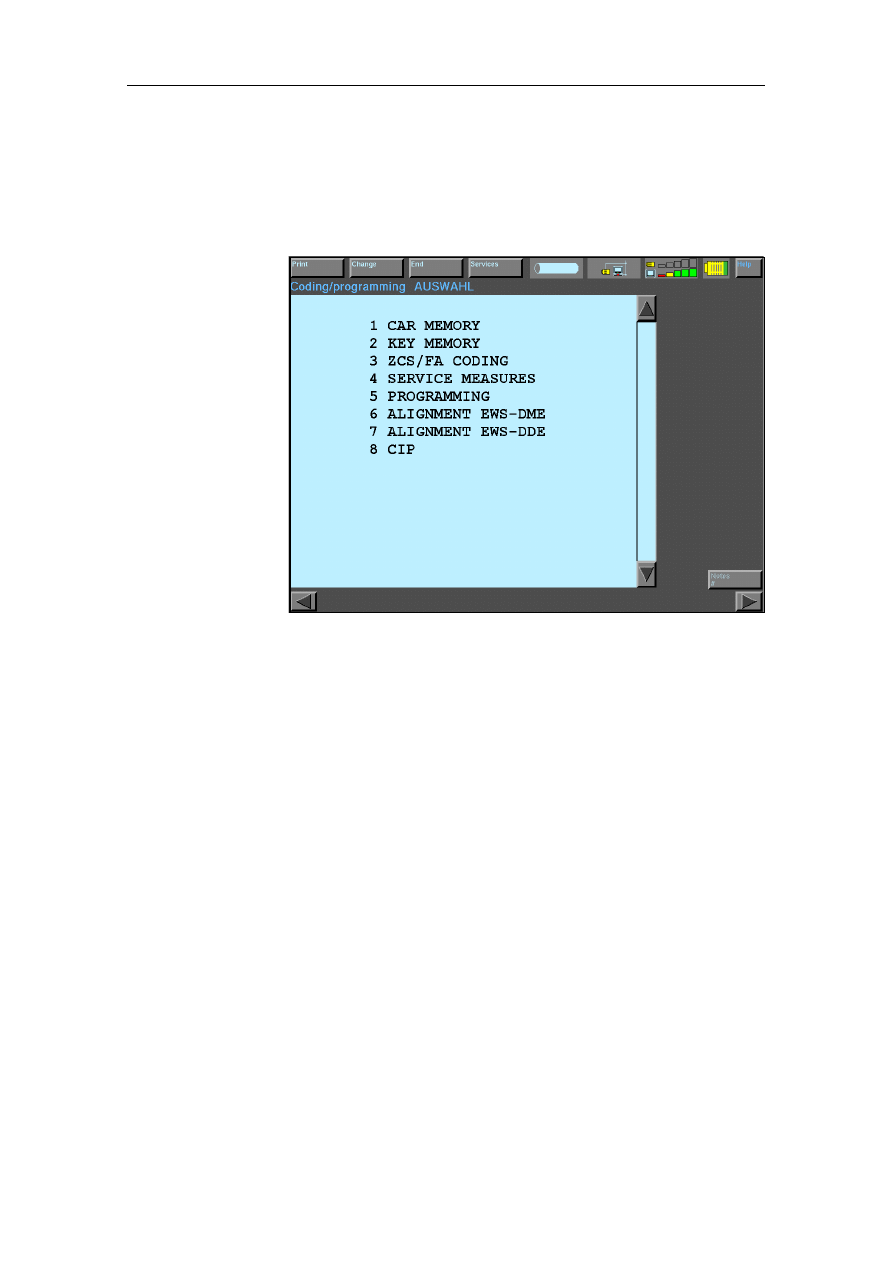
4.5
Coding/Programming
The GT1 can be used to code and recode control units. The cod-
ing program is called up in the start window using the "Coding/
Programming" button. The window shown below appears:
Fig. 4-4
Coding/Programming SELECTION
Select a function in the menu that appears. Follow the instruc-
tions that are then displayed precisely, and confirm execution
with the buttons "Yes", "OK" or "Next".
Operation
BMW Group Tester One, Working with the GT1
Version 2.1, December 2003
4-9
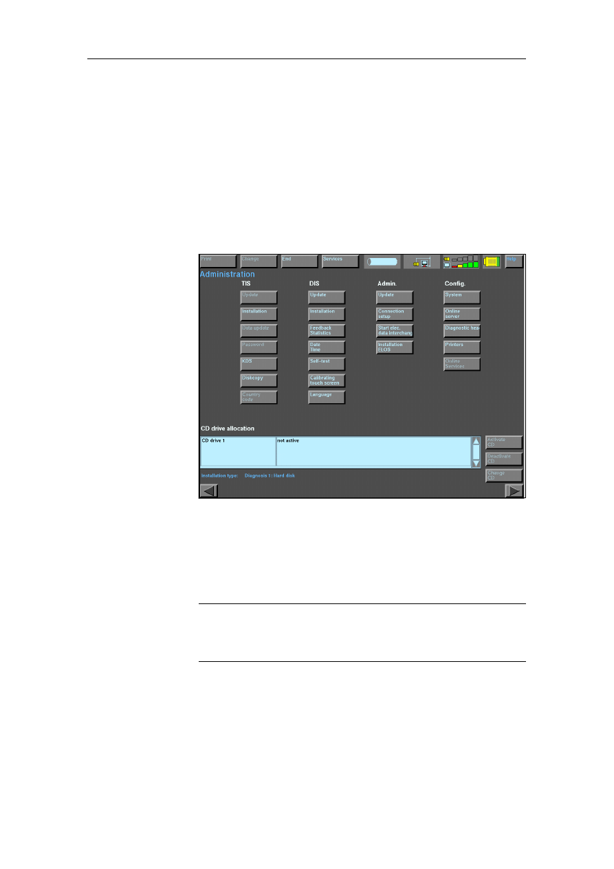
4.6
Administration
The "Administration" operating mode is used for internal admin-
istration of the GT1. Here, you can adapt its settings to your
needs.
You open the Administration using the button of the same name
in the start window and reach the window shown below. This of-
fers you all the available functions in the form of other buttons,
e.g. connection setup via diagnostic head, network configuration
or setting the date and time. The functions made available to you
by Administration depend on the extent of the installed software.
Fig. 4-5
Administration mask
Select a function. Follow the instructions that are then displayed
precisely, and confirm execution with the buttons "Yes", "OK" or
"Next" or cancel the operation.
Note
The administration mask has changed with the introduction of the full network
functionality. Please read the documentation "Full Network Functionality" for
information on the expansion.
Operation
BMW Group Tester One, Working with the GT1
Version 2.1, December 2003
4-10
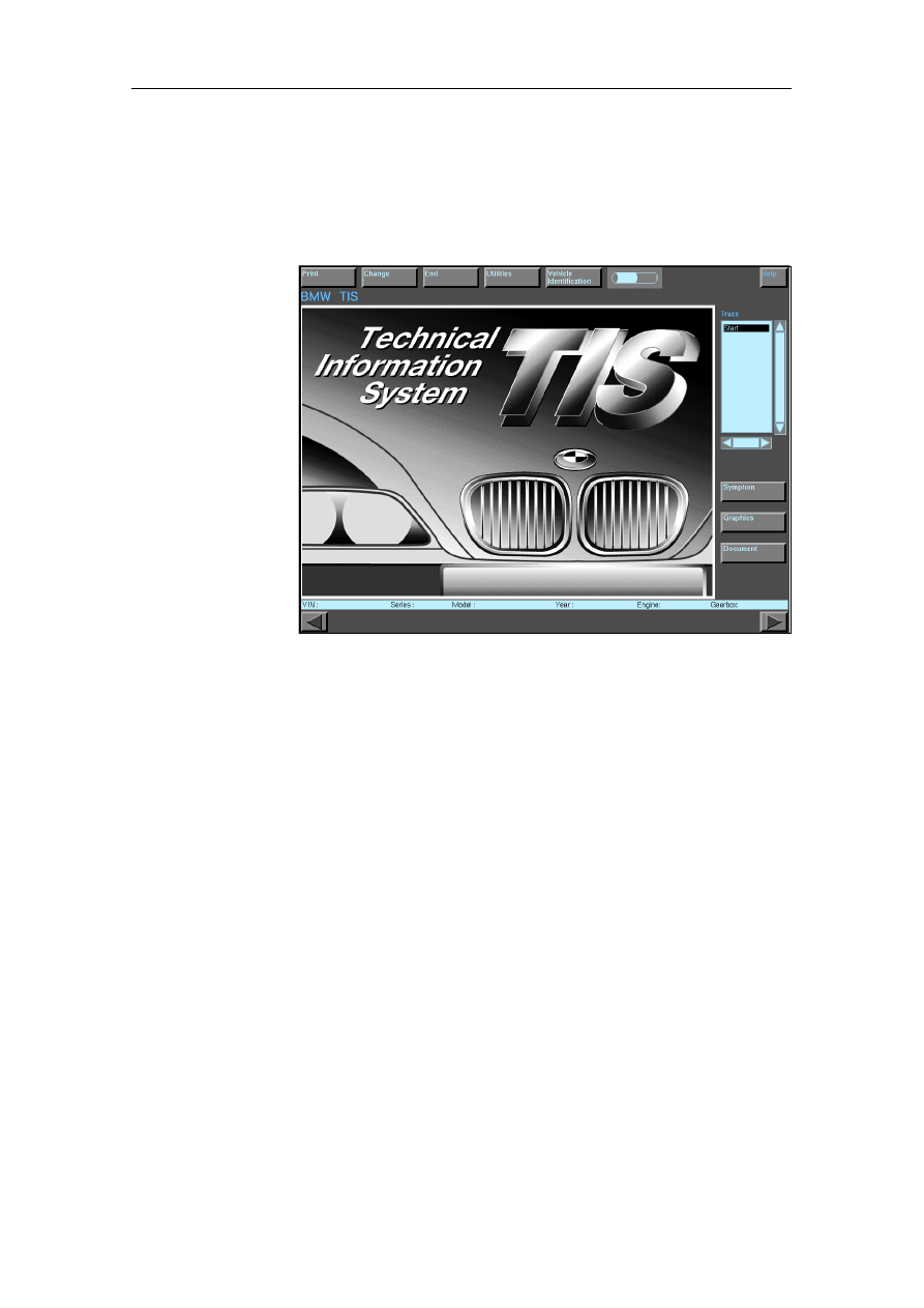
4.7
Technical Information System (TIS)
You reach the Technical Information System by pressing the
"TIS" button in the DIS start window. The window shown below
appears:
Fig. 4-6
Start window for TIS
You can open the TIS from other operating modes by pressing
the "Change" button in the navigation bar and then the "TIS" but-
ton. You can use the "Back" button to return from there to the
original application.
4.8
Help
You can use the "Help" function to call up context-related or
general instructions and explanations of functions. The online
"Help" is not a substitute for the Operating Manual, but it can
provide assistance in workshop use if there is uncertainty re-
garding the operation of windows and buttons without your hav-
ing to consult the Operating Manual.
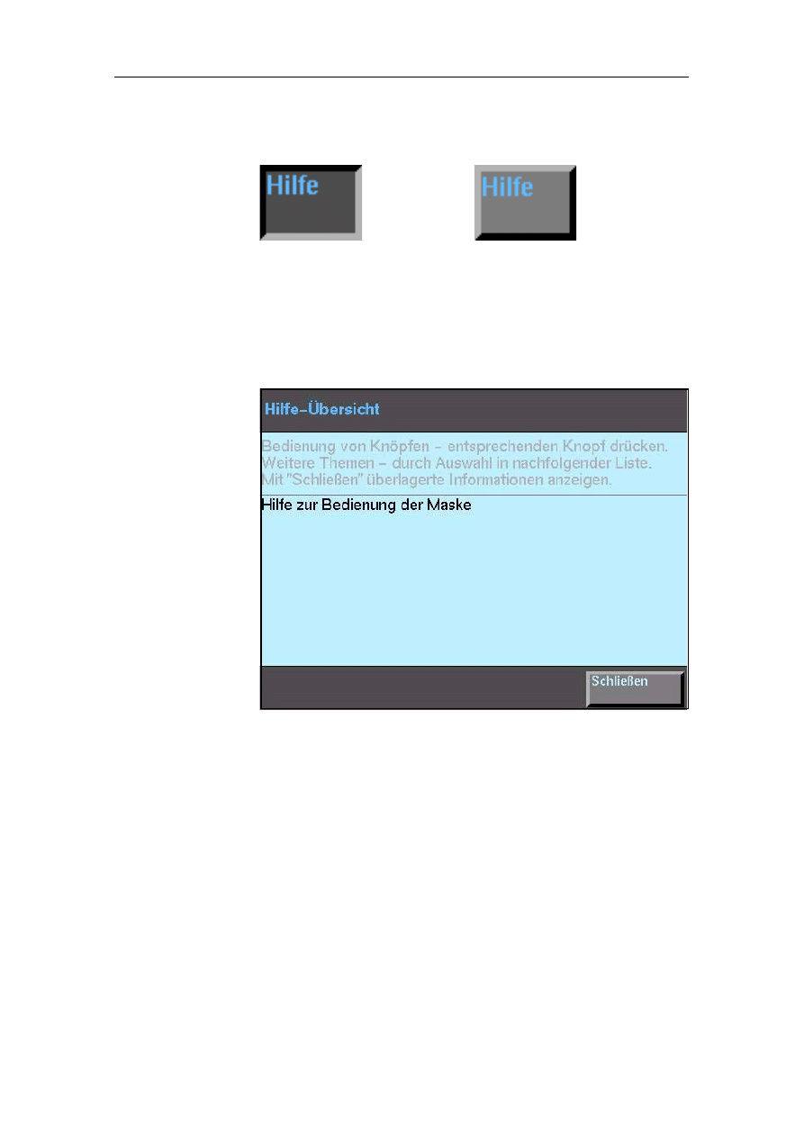
Starting Help
The "Help" button appears in every window of the GT1. It is al-
ways located in the top right of the touch screen. Press it if you
need information on the function of a window or button.
As long as the "Help" button appears as enabled, the GT1 re-
mains in the "Help" function. You cannot change any setting or
selection there. If you press a button on the touch screen sur-
face, the operating unit displays the Help text that explains the
function of the selected screen element.
Operation
BMW Group Tester One, Working with the GT1
Version 2.1, December 2003
4-11
You exit from the "Help" function by pressing the pressed "Help"
button a second time.
Help Contents
When the "Help" function is started, the "Help Contents" dialog
appears. This provides a list with one or more topics for which
brief information is available (see Fig. 6-7).
Fig. 4-7
Help Contents
A selection bar indicates your currently selected topic. You can
move the bar on the touch screen to any list entry; the corre-
sponding topic is opened as soon as you let go of the touch
screen.
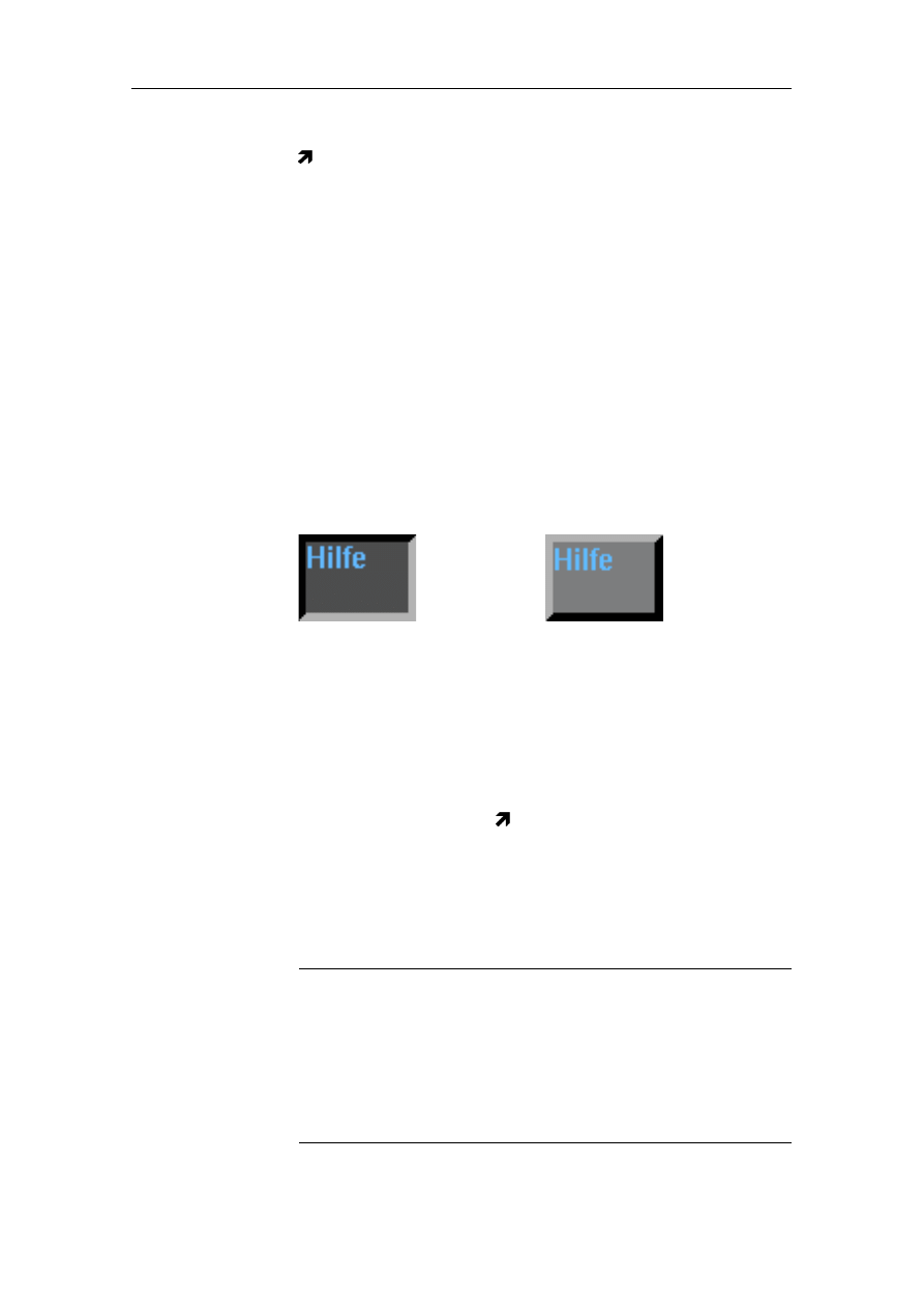
Help is activated -
the button is pressed
Help is not activated
Operation
BMW Group Tester One, Working with the GT1
Version 2.1, December 2003
4-12
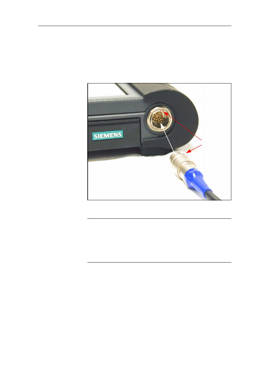
4.9
Measuring Cable
Connect the connector plug of the relevant measuring cable to
the Base measurement system/vehicle electrical system socket.
In doing so, ensure that the red guide points on the connector
and socket are facing one another.
Fig. 4-8
Correct Handling of a Measuring Cable, MFK1 as an Example
Caution
When disconnecting, only grip the plug-in connections at the
connector housing. Never pull the cable directly; it can be dam-
aged otherwise. To disconnect a connector plug from the testing
device, pull the locking sleeve of the connector upwards and si-
multaneously pull the connector from the socket. The connec-
tors have no thread; violent twisting can lead to damage.
Red
guide
dots

Operation
BMW Group Tester One, Working with the GT1
Version 2.1, December 2003
4-13
4.10
Battery
The integrated battery enables mobile operation of the operating
unit for up to 2.5 hours. Information in its charge condition can
be called up in almost every window. The "Services" bar con-
tains an analog display on the right, representing the charge of
the battery.
Fig. 4-9
"Services" Bar with Display of the Charge Status (Arrow)
4.11
Switching Off
To terminate your work with the GT1, press the on/off switch.
Depending on how long the button is pressed, the GT1 is shut
down in one of two ways.
4.11.1 Shutting Down the System
Briefly (approx. 2 seconds) press the on/off switch until an
acoustic signal sounds. The shutdown procedure takes approx.
2 minutes and ends with the touch screen and LED 1 going out.
During this period, you can see an arrow pointing downwards
bearing the following text:
System is coming down.
Switching off the GT1 does not interrupt the battery charging
process. The LED "Battery" also lights up when the operating
unit is switched off, provided it is connected to an external power
supply. It goes out when the battery is fully charged.
Note
A window with the following message appears on the touch
screen: Confirm with OK of you want to switch off or Cancel if
not. This window disappears after a short period if you make no
entry.
Note
The information in the line with the battery indicator has changed as part of the
introduction of the network full functionality. Please read the documentation
"Full Network Functionality".

Operation
BMW Group Tester One, Working with the GT1
Version 2.1, December 2003
4-14
4.11.2 Forced Switch-off
If a fault occurs during operation, and this means that the oper-
ating modes can no longer be operated correctly, you can termi-
nate your work on the GT1 using the forced switch-off and then
restart.
To do so, press the on/off switch for longer than 5 seconds. The
current to the operating unit is cut off.
Caution
A forced switch-off is necessary after a new installation of the
Base CD in accordance with Section 2. Only use it in emergen-
cies when a proper shutdown is not possible, as otherwise there
could be a danger that the installed software becomes inconsis-
tent and has to be newly installed.
Note
In the case of forced switch-off as well, the prompt "Do you really
want to switch off the tester?" appears if the system can still out-
put this message despite the fault situation which has occurred.

Troubleshooting
BMW Group Tester One, Working with the GT1
Version 2.1, December 2003
5-1
5
Troubleshooting
The GT1 is a product of SIEMENS. It was inspected before it left the
factory. Carefully selected components and maintenance of numerous
quality controls guarantee high resistance of the GT1. Should a fault
occur in spite of this, please consult the instructions in this chapter be-
fore contacting the Customer Service responsible.
Faults that can occur on the GT1 can be divided into the following
groups:
•
Faults caused by environmental influences: ambient temperature,
(aggressive) moisture, dust, soot, grease, flying sparks, mains sup-
ply, transformers, large electric motors, radio-control systems, vi-
bration.
•
Faults on the GT1: control panel, docking station, diagnostic head,
cables and other accessories such as keyboard.
Please attempt to determine the fault and localize it as precisely as pos-
sible. Follow the suggested solutions provided and perform all the rec-
ommended measures if possible.
Note
If the fault which has occurred cannot be rectified with the measures
described, contact the SIEMENS Hotline by phone. The telephone
number of the Hotline responsible for you is contained in the documen-
tation "SERVICE ADDRESSES". In cases where practical, you can pre-
pare a Fault Report Fax. The fax number is also contained in the
documentation "SERVICE ADDRESSES".
5.1
Faults: Symptoms/Causes
5.1.1
Self-test
After switching on, the GT1 automatically runs a self-test. It is ready for
operation when the start window is displayed and operation via the
touch screen is possible.
Note
This self-test is not identical to the self-test that can be called up in the
"Administration" operating mode (see section 4.6).
If you receive error messages after this self-test, then send a Fault Re-
port Fax following clarification by phone with the SIEMENS Hotline.

Troubleshooting
BMW Group Tester One, Working with the GT1
Version 2.1, December 2003
5-2
5.1.2
Control Panel
Note
The voltage supply of the operating unit cannot be measured at the
open docking contact, as the voltage is only applied with the docking
action by means of a proximity switch.
Symptom
Possible Causes
Remedy
The system "crashes";
the hourglass no longer
changes back to the
cursor arrow; no opera-
tion possible.
Internal error
If "normal" switching off is not possible, use
a forced switch-off (press the on/off switch
for approx. 5 seconds) to switch the oper-
ating unit off and on again.
with the operating unit
docked, the LED "Oper-
ation" lights up orange.
Power supply of the
docking station inter-
rupted.
Check whether there is power supply volt-
age. Insert the power supply plug correctly.
Operating unit is not
supplied with power via
the docking contact.
Check the spring contacts for soiling or
foreign bodies.
To set up a correct connection, undock and
then re-dock the operating unit two or three
times. See also
If no faults can be determined, send a Fault
Report Fax.
LED "Temperature"
lights up red; operating
unit switches itself off.
Internal temperature
monitoring has been
activated.
Take the operating unit to a cool room and
allow it to cool down adequately. Switching
on the operating unit again.
If the LED "Temperature" lights up without
the presence of a high ambient tempera-
ture, send a Fault Report Fax.
LED "Battery" flashes
yellow on startup for
10 seconds; operating
unit does not start.
After self-shutdown of
the operating unit, there
is still excess tempera-
ture.
Take the operating unit to a cool room and
allow it to cool down adequately. Switching
on the operating unit again.
If the LED "Battery" flashes yellow without
the presence of a high ambient tempera-
ture, send a Fault Report Fax.
System does not power
up completely; gets
'stuck' with an error
message.
Internal run error
Switch the operating unit off (press the on/
off switch for 5 seconds = forced switch-
off) and on again.
If the system still hangs, reinstallation of the
Base CD is necessary.
If this fault occurs repeatedly, send a Fault
Report Fax.
After complete dis-
charge and docking at
the docking station, the
system does not power
up
Deep discharge of the
battery
After a deep discharge and docking at the
docking station, the system can only be
powered up after approx. 3 minutes.

Troubleshooting
BMW Group Tester One, Working with the GT1
Version 2.1, December 2003
5-3
Caution
The
forced switch-off may only be used in the case of special faults. Other-
wise, the operating system can be destroyed and require a new installation!
The
only proper way to shut down the GT1 is by pressing the on/off switch for
approx. 2 seconds (see section 4.11.1).
5.1.3
Touch Screen
Important!
Only use your finger or the supplied touch-pen to operate the touch screen!
Symptom
Possible Causes
Remedy
The cursor does not
react (does not follow
finger contact).
Touch controller
defective or system
'crashed'.
Switch the operating unit off (press the
on/off switch for 5 seconds = forced
switch-off) and on again.
If the fault persists or occurs more
frequently, send a Fault Report Fax.
The touch screen
remains dark; no error
message by means of
LED.
Touch screen in the
energy-saving mode.
No fault. The screen image reappears when
the touch screen is touched.
Backlighting failure.
If you glance sideways at the touch screen,
you can detect vague characters.
Send a Fault Report Fax.
The cursor arrow is not
located beneath the
point of touch (touch
offset).
Touch controller
incorrectly set.
The touch controller must be calibrated: in
the "Administration" window, press the
"Calibrate touch screen" button, enter the
password and follow the instructions that
are displayed.
If this does not eliminate the deviation,
send a Fault Report Fax.
Wrong color of pixels
Individual transistors
defective.
Individual pixels of the wrong color are
tolerable. If entire screen lines or columns
are the wrong color, send a Fault Report
Fax.

Troubleshooting
BMW Group Tester One, Working with the GT1
Version 2.1, December 2003
5-4
5.1.4
Plug-in Connections
Important!
Never use force to insert connectors. The connectors of the mea-
suring and diagnostic cables are marked with a red point that must be
facing a corresponding point on the relevant socket. This is the only
way you can establish a connection!
5.1.5
Battery
Symptom
Possible Causes
Remedy
50 A current clip cannot
be connected.
Connectors of the
current clip do not fit in
the socket.
Use the size 2 adapter.
Cable connection via
LAN interface to diag-
nostic head interrupted.
Plug-in connections of
LAN adapter defective.
Check that the plug-in connections are
correctly seated and undamaged. Check
whether the plug-in connection has been
set up via the LAN operating unit adapter
(uncrossed) and the LAN operating unit
adapter (crossed).
Symptom
Possible Causes
Remedy
LED "Operation" flashes
orange (battery symbol
in the masks is dark).
No power supply,
battery charge is too
low.
Charge the battery by docking at the
docking station (FP).
LED "Battery" lights up
yellow; LED "Operation"
lights up green.
Operating unit switched
on, power supply, bat-
tery being charged.
No fault.
LED "Operation" lights
up alone and green.
Operating unit switched
on, power supply, bat-
tery is charged.
No fault.
LED "Operation" lights
up alone and orange.
Operating unit switched
on, battery power sup-
ply.
No fault.
LED "Battery" lights up
alone and yellow.
Operating unit switched
off, power supply Bat-
tery being charged.
No fault.
LED "Operation" flashes
orange; device does not
power up in battery
mode.
Message: Warning:
Low power......
Battery is too weak.
Charge the battery by docking at the
docking station.
Battery mode does not
work (LED "Battery" is
dark).
Battery defective.
Remove the battery in accordance with the
"Components and Functions" manual
and check the battery voltage. There must
be 12 Volts between the red and black bat-
tery cable. If it can no longer be charged,
replace it in accordance with the "Compo-
nents and Functions" manual.

Troubleshooting
BMW Group Tester One, Working with the GT1
Version 2.1, December 2003
5-5
5.1.6
Printer
Symptom
Possible Causes
Remedy
Local printer does not
print.
Printer connected to
docking station, operat-
ing unit undocked.
Dock the operating unit or insert the USB
cable of the printer in the operating unit.
Check that the connection is correctly
seated.
Printer defective.
In the "Administration" window, press the
"Self-test" button and in the menu that
appears select the "Print test - individual
test" function. The printer should print a
page with the heading "PS". If this does not
occur, check the cable connection to the
printer.
Network printer does
not print.
Network printer con-
nected to docking
station via LAN cable,
operating unit un-
docked.
Dock the operating unit.
Cable connection to
diagnostic head estab-
lished.
Break the cable connection to the diagnos-
tic head and establish a connection to the
network printer (see section 3.2).
Printer defective.
In the "Administration" window, press the
"Self-test" button and in the menu that
appears select the "Print test - individual
test" function. The printer should print a
page with the heading "PS". If this does not
occur, check whether the correct IP ad-
dress of the printer is entered in the
"Administration - Network configuration"
window.

Troubleshooting
BMW Group Tester One, Working with the GT1
Version 2.1, December 2003
5-6
5.1.7
Docking Station
Symptom
Possible Causes
Remedy
No power supply of the
operating unit (LED
"Operation" does not
light up green on dock-
ing when switched on).
No power supply or
power supply plug
disconnected.
Insert the power supply plug. Press the
on/off switch.
Docking contacts
soiled.
Carefully clean the contacts at the docking
station with a lint-free cloth.
Foreign body prevents
perfect contact of the
plug-in contacts.
Remove the foreign body.
Proximity switch is
defective, does not
switch the voltage
through.
Send a Fault Report Fax.
Power supply unit
defective.
Send a Fault Report Fax.
LED defective.
Send a Fault Report Fax.
LED "Battery" does not
light up orange when
switched off.
Battery is fully charged. No fault.
Docking contacts
soiled.
Carefully clean the contacts at the docking
station with a lint-free cloth.
Power supply unit
defective.
Send a Fault Report Fax.
LED defective.
Send a Fault Report Fax.

Troubleshooting
BMW Group Tester One, Working with the GT1
Version 2.1, December 2003
5-7
5.1.8
Diagnostic Head
Symptom
Possible Causes
Remedy
No connection possible
(LED 1 on diagnostic
head is dark).
No power supply of the
diagnostic head via
vehicle electrical sys-
tem.
First check the plug-in contact of the
diagnostic cable BMW or OBD and its
connection with the vehicle.
Switch the ignition on.
If the LED still does not light up, send a
Fault Report Fax.
Connection to the
diagnostic head not
possible or faulty (LED 2
flashes yellow); no
diagnostic head is
recognized (see
"Administration, Diag-
nostic head allocation "
window). The diagnos-
tic head cannot be
connected.
Disrupting influence
due to excessively large
distance to vehicle; in
the case of radio link,
also due to exterior
radio sources or
absorption.
Check the correct connection of the cables
at the diagnostic head.
Change the location of the diagnostic head,
if necessary also of the operating unit.
If this does not remedy the fault, change the
connection type.
If no connection can be set up, send a Fault
Report Fax.
Diagnostic head
software faulty.
Perform a reinstallation.
Incorrect IP address on
changing the diagnostic
head.
Check the IP address in the "Administra-
tion, Network configuration" window.
Radio card in the
diagnostic head defec-
tive.
If possible, use the second diagnostic head
to check the radio link. If the connection
can be established, the card in the first
diagnostic head is defective. Send a Fault
Report Fax.
Radio card in the
operating unit defective.
If possible, use the second diagnostic head
to check the radio link. If no connection can
be established with this either, the card in
the operating unit might be defective.
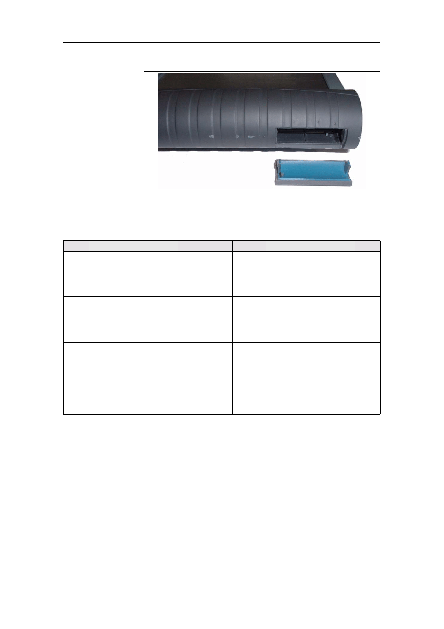
If you use a suitable tool, e.g. a screwdriver,
to lever the cover off the radio card slot in
the left handle of the operating unit (see Fig.
7-1), you can see a green and a yellow LED
on the radio board. If the green LED is on,
the radio board is OK. If the yellow LED is
flashing rapidly, there is correct data com-
munication.
If you discover that the LEDs are in any
other state, send a Fault Report Fax.
LED 3 flashing red.
Interior temperature of
the diagnostic head too
high.
Terminate the diagnosis. Break the
connection and allow the diagnostic head
to cool adequately before you use it again.
LED 1 flashing rapidly.
General fault in the
diagnostic head.
Send a Fault Report Fax.
"Recorder" button on
the back lights up
green.
Only during the launch. No fault.
This button has no function at this time.
Troubleshooting
BMW Group Tester One, Working with the GT1
Version 2.1, December 2003
5-8
Fig. 5-1
PCMCIA interface (radio card slot) with opened cover
5.1.9
Accessories
Symptom
Possible Causes
Remedy
No measurements
possible with MFK 1.
Measuring head
defective.
In "Administration", run a self-test of the
MFK 1.
In the event of an error message regarding
the measurement system or measuring
cable, send a Fault Report Fax.
No measurements
possible with MFK 2.
Measuring head
defective.
In "Administration", run a self-test of the
MFK 2.
In the event of an error message regarding
the measurement system or measuring
cable, send a Fault Report Fax.
No input possible using
the optical keyboard.
No IR connection
possible or batteries
discharged.
Check whether the transmit and receive
windows of the infrared connection are
covered. Change the distance between the
devices.
Replace the batteries of the optical
keyboard.
If no connection can be set up, send a Fault
Report Fax.

Troubleshooting
BMW Group Tester One, Working with the GT1
Version 2.1, December 2003
5-9
5.2
Fault Codes
Faults can occur when you are working with the GT1, and these can
have a variety of causes. Most fault or error messages are supplement-
ed by a fault message text indicating possible incorrect operation.
Example: If the MFK 1 or the current clip are not connected when the
measurement system is switched on, measurement system faults are
displayed, e.g.:
Fault code 500.894 "Connect the measuring cable MFK1"
Fault code 500.871 "Connect the measuring cable current clip".
These fault codes are stored in so-called code volumes: the first three
positions indicate the type of fault; separated by a period, the last three
positions give a precise indication of the fault. In many cases, a plain
text describes the fault or how to remedy it.
Table 5-1
Fault codes
Codes
Fault Group
000
System error from UNIX operating system
100
Fault in the measurement system, internal
200
Fault in the EDIC application
300
Fault in the system technology
400
Fault in the TOROS application
500
Fault in the measurement system application
800
Run error
900
Internal error

Troubleshooting
BMW Group Tester One, Working with the GT1
Version 2.1, December 2003
5-10

Forms and Addresses
BMW Group Tester One, Working with the GT1
Version 2.1, December 2003
6-1
6
Forms and Addresses
6.1
Online Registration
If you have access to the Internet, the simplest way to register your GT1
is online.
1. Start your Web browser and enter the address
www.siemens.de/sidis. The Siemens SIDIS homepage appears.
2. In the top menu bar, choose between the languages "German" and
"English".
3. Clicking the "Service" menu item in the left menu bar sets up a new
page.
4. In the left menu bar, select the "For users" menu item.
5. On the next page, select the "Online Registration" menu item.
6. On the "Online Registration" page, enter the identification "GT1" in
the first field and the four-digit system number of your GT1 (see
"Components and Functions" manual) in the second field.
7. Press the "Send" button.
8. In the "GT1 Online Registration" form that is now set up, enter the
required data. Mandatory fields where you must make an entry are
indicated by an asterisk.
9. Select the "Send" button. You receive a note to the effect that the
data have been sent successfully.
This concludes the registration procedure. Break the online connection
and close your browser.
6.2
Forms for Registration / Fault Reports
The "Registration" and "Fault Report" forms are located on the docu-
mentation CD under "SERVICE ADDRESSES".
Use copies of these forms. File the pages faxed to the Customer Ser-
vice.

Forms and Addresses
BMW Group Tester One, Working with the GT1
Version 2.1, December 2003
6-2
6.3
Service Addresses
The address list with the SERVICE ADDRESSES is continually correct-
ed and updated.
If no center is specified as responsible for your country, please contact
the SIEMENS office in Germany.
The current service addresses of the SIEMENS Hotline are provided on
the documentation CD under "SERVICE ADDRESSES".
This documentation also contains the "Registration" and "Fault
Report" forms.
Note
Please only report a hardware or software fault to one of the responsible
SIEMENS Hotlines.
Terms and Abbreviations
BMW Group Tester One, Working with the GT1
Version 2.1, December 2003
7-1
7
Terms and Abbreviations
7.1
Definitions
Term
Explanation
System
The software installed in the control panel.
Alpha-numeric
keypad
Keypad that can be used to enter numbers and
letters.
Selection Bar
Optical highlighting of a selected line in a list by
means of a dark (inverted) bar.
Services
Functions in the top section of the
window
switch from the current display into other
functions or
operating modes or to close
them.
Touch-screen
(sensitive user
interface)
Monitor that has a touch-sensitive surface. The
corresponding hardware and software reacts to
contact by objects such as a finger or a touch-
pen, detects the touched position and starts up
the
function linked to it (e.g. a button). The
touch screen replaces externally connected in-
put devices such as keyboard, mouse, etc.
Operating Mode
Each of the applications of the control panel that
can be started from the
start window: "Diag-
nosis", "Measurement System", "Administration"
etc. Each operating mode is divided into a num-
ber of individual functions.
Screen dump (hard-
copy)
Paper printout of the screen contents (
window
etc.).
Button
A button located in a window which changes
from unpressed to pressed and starts a function.
CD-ROM
C
ompact
D
isk -
R
ead
O
nly
M
emory: a data me-
dium, externally similar to a music CD, that can
only be read, not written.
COM
"Communication": Designation of the serial in-
terface.
Deselection,
deselect
Canceling a choice of program function or list
entry.
Selection.
Diagnosis
The entire process of allocation between
fault
patterns and possible defective functions, as-
sembly groups or components, up to and includ-
ing locating of a defective component of a Can
take place by calling up expert knowledge from
the software data or directly through expert
knowledge on the part of the user. Occasionally,
the result of the processes is also termed "diag-
nosis".
Diagnosis
connection
Connecting socket for the
diagnostic cable on
the diagnostic head.
Diagnostic Cable
Connecting cable between vehicle and diagnos-
tic head.
Terms and Abbreviations
BMW Group Tester One, Working with the GT1
Version 2.1, December 2003
7-2
DVD
D
igital
V
ersatile
D
isk: data storage medium sim-
ilar to a
CD-ROM, but with greater information
density.
Energy-saving mode
(standby mode)
Advanced Power Management (APM): If the
touch screen is not touched for 10 minutes, the
tester switches the display off to save power.
The
system continues to run. To switch on the
screen display again, briefly touch any point on
the touch screen.
Vehicle system
A control unit known by name, including the
corresponding sensors, actuators and wiring.
Fault pattern
The overall effects (
fault symptom) of a mal-
function of vehicle functions, assembly groups
or components.
Fault symptom
A describable effect of a malfunction of vehicle
functions, assembly groups or components. The
symptoms together produce the
fault pattern.
In the software data of the vehicle diagnosis
system, known symptoms are stored with allo-
cations to suspicious functions, assemblies and
components.
Diagnosis.
Windows
Screen display with defined layout in different
graphical elements such as fields, buttons,
scrollbars, etc.
Firewire
Interface IEEE 1394 for serial data transmission
with high speed.
Function
Every operation that the control panel can run in
its various
operating modes. Individual func-
tions are usually selected from a list displayed on
the monitor.
IP Address
I
nternet
P
rotocol
A
ddress: Each station in a
TCP/IP network uses a unique IP address. This
consists of four byte values that can be set in the
range from 0 - 255. The four segments (quads)
are separated by periods.
Network mask.
LAN
L
ocal
A
rea
N
etwork: In contrast to a WAN (Wide
Area Network), this connects workstations and
networks in more than one region. "Local" in this
sense refers to a shared location, for example
company premises or a single room.
Navigation Bar
Functions in the lower section of the
window
to switch from the current display into other
functions.
Network mask
The network mask (frequently also termed
subnet mask) determines which segments of an
IP address determine the network and which
segments the station. A usual setting is
"255.255.255.0", whereby the last "0" specifies
that the fourth segment indicates the station. All
stations of a workshop network have the same
network ID, but different station IDs.
Numeric keypad
Keypad that can be used to enter numbers but
no texts.
Term
Explanation
Terms and Abbreviations
BMW Group Tester One, Working with the GT1
Version 2.1, December 2003
7-3
Table 7-1
Terms and Explanations
Pull-down menu
Selection menu that the operating unit brings
onto the screen when certain buttons in the
"Services" line are operated.
Pull-up menu
Selection menu that the operating unit brings
onto the screen when certain buttons in the
navigation bar are operated.
Selection, select
Selection of an element from a list. The selected
element is highlighted on the screen by a
se-
lection bar. Deselection, Preselection.
Start window
The representation shown on the screen by the
control panel after powering up. A choice of its
four
operating modes can be started here.
Can be recognized by the
start graphic.
Start graphic
Picture of a vehicle that appears in the
start
window.
Control Unit
Electronic device for controlling and monitoring
vehicle functions. Vehicle system
Subnet mask
Other designation for
network mask.
USB
U
niversal
S
erial
B
us: Standard interface across
which the peripheral devices, e.g. an external
floppy disk drive, can be operated.
Virtual keyboard
The graphical image of a keyboard on the
touch screen. The individual buttons can be
activated by finger pressure in the same way as
with a real keyboard. The control panel can offer
alpha-numeric or also
numeric keypads.
Preselection
The suggestion of the control panel to start one
of several functions from the current
window.
The preselection is shown on the screen by the
selection bar. It can be changed at any time
. Selection.
Term
Explanation

Terms and Abbreviations
BMW Group Tester One, Working with the GT1
Version 2.1, December 2003
7-4
7.2
List of Abbreviations
Table 7-2
Abbreviations
Abbreviation
Explanation
APM
Advanced Power Management
BMW AG
Bayerische Motoren Werke AG
CD
Compact Disk
COM
Communication
DIS
Diagnosis and Information System
DVD
Digital Versatile Disk
GT1
Group Tester One
IP Address
Internet Protocol Address
IR
Infrared
LAN
Local Area Network
LED
Light Emitting Diode
MFK
Multifunction Cable
OBD
On-Board Diagnostics
PCMCIA
Personal Computer Memory Card International
Association
CU
Control Unit
SIDIS
Siemens Diagnosis and Information System
TCP/IP
Transmission Control Protocol/Internet Protocol
TD
Transistorized speed sensor signal
TIS
Technical Information System
USB
Universal Serial Bus
VGA
Video Graphic Adapter


We have checked to ensure that the content of the printed matter
matches the hardware and software described. Nonetheless, devi-
ations cannot be excluded and we are unable to provide a guaran-
tee that the match is complete. However, the information provided
in this printed matter is checked regularly, and necessary correc-
tions are included in subsequent issues. We are grateful for all sug-
gested improvements.
The right to make changes of a technical nature is reserved.
Transfer or duplication of this document, as well as use or commu-
nication of its content are not permitted unless express consent is
granted. Violations give rise to claims for damages. All rights re-
served, in particular pending patent rights.
Copyright © BMW AG 2003 All Rights Reserved
BMW Aktiengesellschaft
UE / Printed in Germany
Document Outline
- 1 General Information
- 2 Installing Software
- 3 Network Configuration
- 4 Operation
- 5 Troubleshooting
- 6 Forms and Addresses
- 7 Terms and Abbreviations
Wyszukiwarka
Podobne podstrony:
AMACOM, A Survival Guide for Working With Bad Bosses Dealing With Bullies, Idiots, Back stabber
GWT Working with the Google Web Toolkit (2006 05 31)
18 Lesson18 Working With Templates
(Ebook English) Crafts Beading Working With Metal Clay
Benefits of Working with a Coach
Working with agar
Working with Dryads
Working with Sources
#0936 Working With the IT Department
Working with Oneness by Llewellyn Vaughan Lee
MAPS Vol11 No2 Working with Difficult Psychedelic Experiences
Handbook for Working with Defendants and Offenders with Mental Disorders Third Edition
FIDE Trainers Surveys 2017 05 19 Miguel Illescas Working with Computers
AMACOM, A Survival Guide for Working With Bad Bosses Dealing With Bullies, Idiots, Back stabbers, A
ASP NET Module 1 Working with Microsoft ASP NET
Greg Webb The All Magic Reader Working With Stage Thread
#0752 – Working With Unreliable People
więcej podobnych podstron