142
ELECTRONIC DESIGN / MA
Y 27, 1997
IDEAS FOR DESIGN
A
dc-ac inverter circuit generates
the high-voltage ac signal re-
quired to drive an electrolumi-
nescent (EL) panel. An EL panel is a
strip of plastic that’s coated with a
phosphorous material. When a high-
voltage ac signal, which is at least 40
V or greater, is applied across this
panel, it emits light. The brightness
of this light depends on the ampli-
tude and frequency of the voltage
waveform applied across the panel.
As the voltage or frequency of the
driving signal increases, the bright-
ness of the lamp increases.
EL panels can be used to backlight
LCD displays, keypads, or other
types of user interfaces. EL lamps
typically consume less power than
LEDs, which suits them for back-
lighting battery-powered products,
such as pagers, calculators,cellular
phones, and so on.
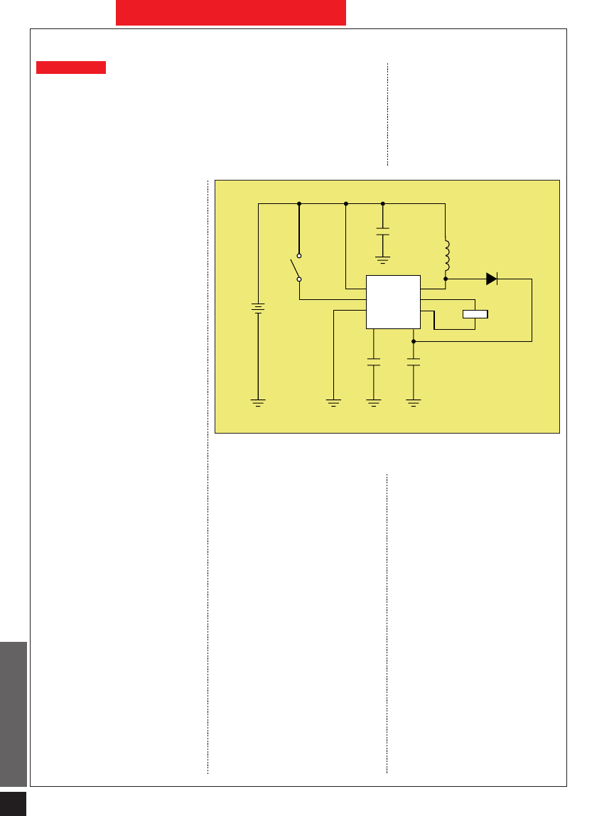
The circuit shown uses the SP4425
IC along with a few other compo-
nents to convert a 1.5-V battery sup-
ply to a high-voltage square-wave
output (see the figure). This square-
wave output is applied across the EL
panel, causing it to illuminate.
The SP4425 IC contains an inter-
nal oscillator that drives an internal
high-power bipolar junction transis-
tor switch. The oscillator frequency is
set by C2, which is 180 pF, and is ap-
proximately 22 kHz. The switch is
connected between one end of the
470-
µ
H inductor and ground. The
other end of the inductor is connected
to the battery voltage.
When the switch is turned on, a
low impedance path is provided be-
tween the inductor and ground. This
causes the current flowing through
the inductor to increase. As the cur-
rent through the inductor increases,
energy is stored in the inductor in the
form of magnetic flux. When the
switch is turned off, this stored en-
ergy is transferred through a diode
(D1) to a 0.1-
µ
F capacitor. This
process is repeated continually, caus-
ing the voltage across the capacitor to
increase with each cycle. For a one-
square-inch-size lamp, the voltage
across C1 will increase to a dc level in
the range of 50 to 70 V. This voltage is
then fed back into the IC at pin 4.
Within the IC is an internal H-
bridge circuit and a frequency divider.
The frequency divider divides the os-
cillator frequency down by a factor of
64. Therefore, the frequency divider’s
output is approximately 343 Hz. The
H-bridge along with the frequency di-
vider convert the dc voltage at pin 4
into a 343-Hz square wave. The volt-
age amplitude of this square wave is
50 to 70 V, and is approximately equal
to the voltage across C1.
Two complementary square-wave
outputs are provided by the IC at pin
5 and pin 6. Both outputs are equal in
amplitude, but are 180° out of phase
with each other. The EL lamp is con-
nected between these two comple-
mentary outputs, resulting in a dif-
ferential voltage across the lamp
that’s twice the amplitude of a single
square-wave output. The brightness
of the lamp typically can range from 3
to 5 foot-lamberts, depending on the
dc resistance of the inductor.
This dc-ac inverter circuit is in-
tended for battery-powered applica-
tions, in which the display is only re-
quired to be illuminated for short
periods of time. Therefore, S1 is con-
nected to pin 8 and is used to enable
or disable the circuit. When S1 is
closed and pin 8 is pulled up to the
supply voltage, the IC is enabled.
When S1 is opened, an internal pull-
down resistor in the IC causes the
voltage at pin 8 to be pulled to
ground. This disables the IC and puts
the circuit in a low-current standby
mode. C3 is used as a decoupling ca-
pacitor for the IC supply pin. The
supply pin must be sufficiently by-
passed because large current tran-
sients are drawn from the battery
when the circuit is functioning.
DC-AC Inverter Targets
Electroluminescent Applications
JOEY MARTIN ESTEVES
Sipex Corp., 491 Fairview Way, Milpitas, CA 95035; (408) 945-9080.
Circle 521
+
–
VI
S1
C3
D1
1N4148
470
mH
L1
C2
180 pF
C1
0.1
mF
0.1
mF
El Lamp
7
8
2
3
6
5
SP4425
VD
ELEN
VS
C2
COIL
EL1
EL2
CAP
U1
1
4
This dc-ac inverter circuit, intended for battery-powered electroluminescent applications,
converts a 1.5-V battery supply to a high-voltage square-wave output.
Wyszukiwarka
Podobne podstrony:
A Study Of Series Resonant Dc Ac Inverter
Modified PWM Control for the DC AC Inverter With a Non Constant Voltage Source
DC AC inverter
A Study Of Series Resonant Dc Ac Inverter
DC AC Inverter Unit for Liquid Crystal Display (LCD) Panel
Modified PWM Control for the DC AC Inverter With a Non Constant Voltage Source
12V DC to 230V AC Inverter, 12v 230v inv
A Novel Switch Mode Dc To Ac Inverter With Nonlinear Robust Control
A Novel Switch mode DC to AC Inverter With Non linear Robust Control
A Novel Switch Mode Dc To Ac Inverter With Non Linear Robust Control
Dc To Ac Inverter With The 555
A Novel Switch Mode Dc To Ac Inverter With Non Linear Robust Control(1)
Consular Electronic Application Center Print Application
03 Skompensowany przemiennik czestotliwosci AC DC AC
00329965 Quasi Parallel Resonant Dc Link Inverter With Improved Pwm Capability
09 Przetworniki AC DC i DC AC (2)
EN w6 przekszt imp dc ac
więcej podobnych podstron