
DC/ AC Inverter Unit for Liquid Crystal Display (LCD) Panel
DC-AC INVERTER UNIT
PAGE
1
APPLICATION NOTE
1. Introduction
Liquid crystal display (LCD) panels are used in various applications ranging from smaller portable electronic
equipment to larger fixed location units. Applications such as the display device for laptop PCs, word processors,
arcade game machines, pinball machines, video cameras, automobile navigation systems, and industrial machines.
The LCD panel itself cannot emit light. Therefore, a backlight system that supplies the light from behind is normally
required. The backlight system consists of a light emitting device that produces light, a conductor panel that
distributes the light to the entire LCD surface uniformly, and a power supply that drives the light emitting device.
Currently, the most commonly used light emitting device is a fluorescent tube called a cold cathode tube or CCFL.
The CCFL is called a cold cathode tube because even though the principle of illumination is the same as that of the
hot cathode tubes used by indoor lamps, this lamp does not require preheating of the filament. Also, the electrodes at
the end of the bulb stay at a low temperature while emitting light. A special power supply, inverter, which generates
approximately 1000 to 1500V AC is required to drive a CCFL. This inverter is a small power supply used to make this
CCFL illuminate, and is one of the important functional parts of a complete LCD display.
As LCD panels are used in various markets and applications, requirements for the backlight system have become
diversified as shown in table 1. In particular, the European computer display market is evolving from CRT displays to
the LCD displays, this is partly due to strict EMI emission regulations.
Table 1
The balance of this application note will discuss the basic operation, features, and design precautions of the most
commonly used inverters. We will also discuss inverter requirements and selection methods for those planning to use
LCD panels.
In order to select the proper inverter unit, it is necessary to understand the features of the CCFL that is the load of
the inverter. For those users who use LCD panels for laptop PCs and first-time users of backlighting systems, the
fundamental features and basic operating principles of the CCFL and the inverter resonant push-pull circuit are
explained.
DC/AC Inverter characteristic applied to various
Market
Audio & Visual
View Finder
Video Monitor
LCD TV
LCD Monitor
Automotive
Navigation
Computer
Note PC
PCS
Communication
Pager
Others
Game
Monitor
DC/AC Inverter characteristic
Downsizing
Efficiency
Life
Wide Dimming
ooo
ooo
o
oo
ooo
oo
oo
ooo
oo
oo
oo
ooo
oo
oo
oo
ooo
oo
oo
ooo
ooo
oo
ooo
ooo
oo
oo
ooo
oo
oo
oo
ooo
oo
oo
oo
ooo
DC/ AC Inverter Unit for Liquid Crystal Display (LCD) Panel
DC-AC INVERTER UNIT
PAGE
2
APPLICATION NOTE
2.0 Characteristics of the cold cathode tube
The brightness and the electrical characteristics of the CCFL change depending on the ambient temperature. Specific
characteristics such as the length and diameter of the CCFL as well as the type and pressure of the gas, will also
affect these electrical characteristics. Therefore, it is necessary to check the characteristics of the specific CCFL that
you plan to use.
Discharge in the cold cathode tube
In a CCFL, the discharge starts when electrons and positive ions, which are accelerated by the high electric field,
collide with the surface of the cathode such that secondary electrons are emitted. After the initial discharge starts a
lower voltage is required to maintain the discharge. The CCFL emits ultraviolet light caused by the ejection of the
secondary electrons. This ultraviolet light strikes the fluorescent material painted on the tube surface and emits
visible light. Depending on the size of the LCD panel the typical CCFL diameter is 2 to 3mm and lengths vary from
about 50 to 280mm.
Discharge startup time and the tube voltage
The discharge starts when a high voltage of about 1000Vrms is applied between both electrodes of the CCFL. This
voltage is called the discharge starting voltage. (It is also sometimes referred to as the startup voltage or initial
voltage.)
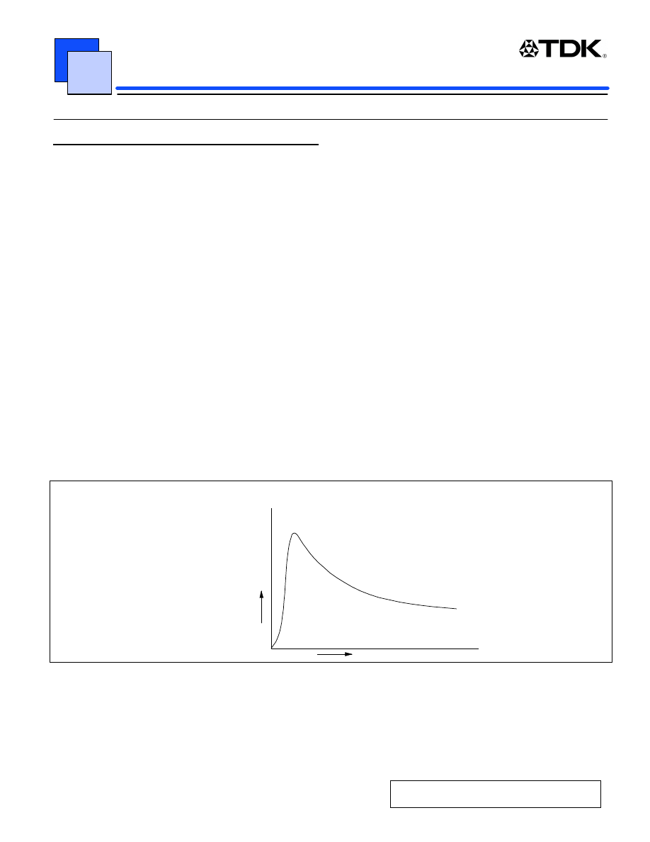
When current flows through the CCFL, the impedance of the tube decreases and the voltage between the electrodes
of the CCFL drops rapidly. When current flows to a certain level, decline of the voltage stops and the CCFL shows an
almost constant voltage characteristic as shown in Figure 1. The voltage at this time is called the CCFL voltage and it
is approximately 300 to 700Vrms, depending on the type of the CCFL. Though this characteristic resembles that of
the zener diode, the CCFL has a negative constant voltage characteristic where the voltage drops when current
increases, whereas the voltage in a zener diode rises when current increases, giving it a positive constant voltage
characteristic.
CCFL Voltage vs. Current
Voltage (V)
Current (I)
Figure 1
In general, the starting voltage and the CCFL voltage tend to be higher under the following conditions:
žWhen the ambient temperature is low.
žWhen the diameter of the cold cathode tube is small.
žWhen the length of the CCFL is long.
DC/ AC Inverter Unit for Liquid Crystal Display (LCD) Panel
DC-AC INVERTER UNIT
PAGE
3
APPLICATION NOTE
In order to ensure that the CCFL starts, a starting voltage of 1000 to 1500Vrms, which is higher than the operating
voltage of the CCFL, is required as the inverter generates the open voltage (a voltage that the inverter generates
before the discharge starts).
CCFL current and brightness
In order to maintain the discharge after starting, it is necessary to keep current flowing. Even though the brightness
increases by increasing current to the CCFL, too much current may damage the electrodes and lead to a shorter
lifetime. While 2 to 7ma is commonly used for each CCFL, it is important to control the current at an appropriate
level. Reference should be made to the brightness verses rated current listed in the specification sheet of the CCFL.
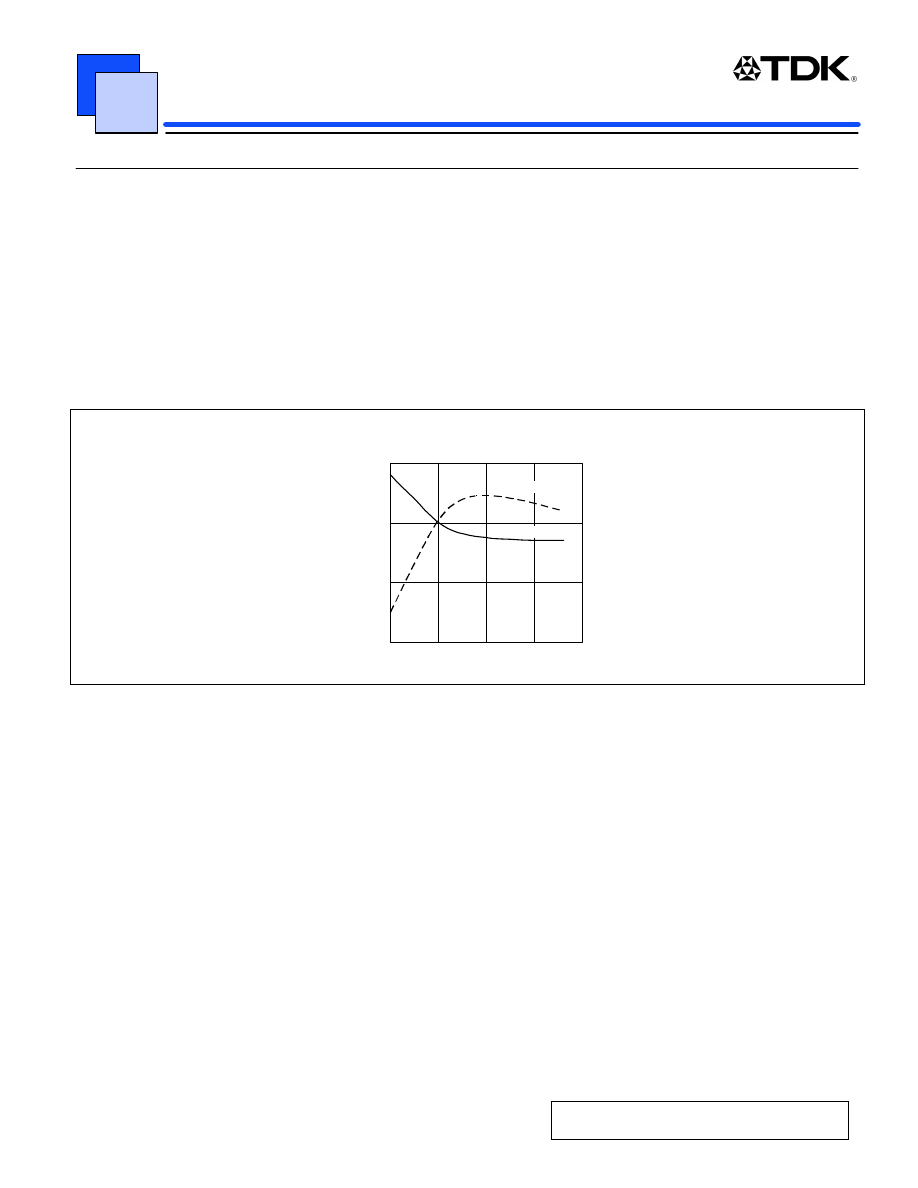
Figure 2 is an example of CCFL brightness verses starting voltage and temperature. When the ambient temperature
is lower as shown in Figure 2, the brightness decreases as opposed to the rising starting voltage.
Lamp brightness and starting voltage vs. temperature
Temperature(C)
(%)
0
50
100
150
0
20
40
60
80
Brightness
Starting Voltage
Figure 2
Frequency
Generally, CCFL’s are lit by alternating current (AC). This is because when direct current (DC) is used, the mercury
ions in the cold cathode tube are shifted, the intensity of the tube becomes unbalanced (catapholesis phenomenon),
and the life of the CCFL will be shorter. The AC frequency is typically 30 to 70 kHz. The higher the frequency, the
greater the light output. Due to current leakage through the wiring capacitance between the inverter and the CCFL,
light output to power efficiency may decrease. This is because not all of the output current from the inverter flows to
the CCFL. In addition, it is necessary to consider the interaction with the LCD refresh frequency to avoid flickers and
noise streaks that can occur from interference from the operating frequency of the LCD panel.
It is necessary to consult the CCFL specification regarding these and other characteristics. Other light characteristics
to consider are the color temperature and color spectrum of the individual lamp.
DC/ AC Inverter Unit for Liquid Crystal Display (LCD) Panel
DC-AC INVERTER UNIT
PAGE
4
APPLICATION NOTE
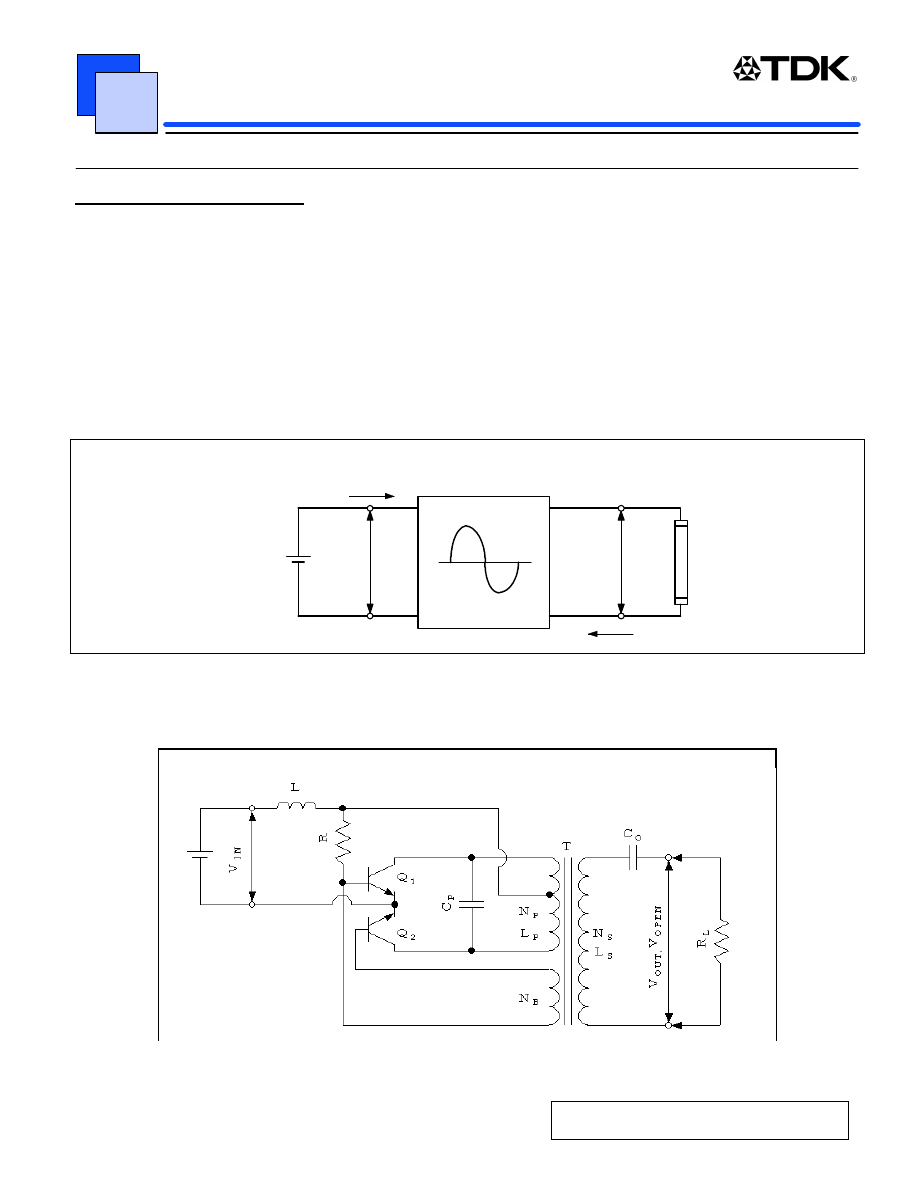
2.1 Fundamental operation
In order to select the appropriate inverter it is necessary to understand the basic theory of operation. When the
inverter is considered as a black box, there are seven parameters that can be given from outside as shown in Figure
3:
Input voltage V
IN
Input voltage to the inverter.
Input current I
IN
Input current to the inverter.
Output voltage V
OUT
CCFL voltage between the electrodes after the discharge has started.
Open voltage V
OPEN
Voltage necessary to start the discharge in the CCFL.
Equivalent load resistance R
L
Equivalent resistance obtained by dividing the CCFL voltage by the CCFL current.
Output current I
OUT
CCFL Current
Oscillator frequency f
Frequency used when the CCFL is driven by alternating current.
Outline of parameters
(Lamp)
f
I
in
V
in
V
out
, V
open
I
out
R
L
Figure 3
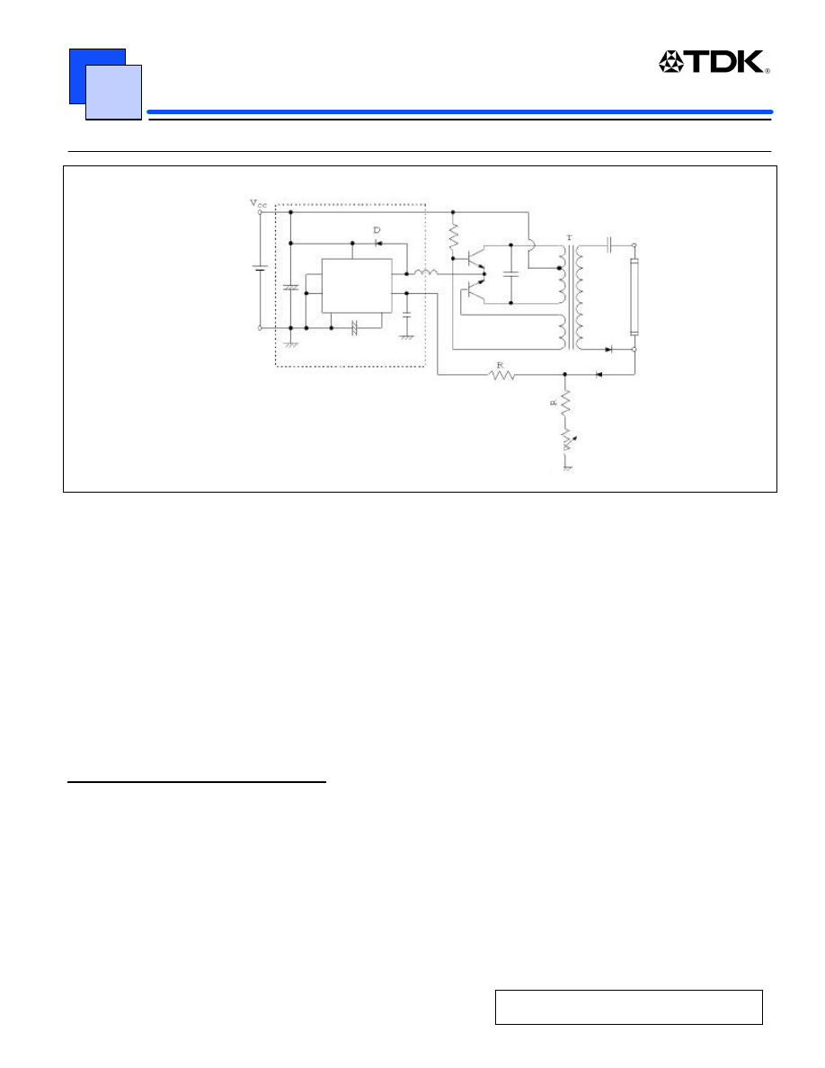
DC/AC Inverter basic circuit
Figure 4
DC/ AC Inverter Unit for Liquid Crystal Display (LCD) Panel
DC-AC INVERTER UNIT
PAGE
5
APPLICATION NOTE
Figure 4 shows the basic inverter circuit. (Push-pull voltage resonant circuit) This circuit is suitable for CCFL’s. This
circuit can generate a symmetric sine wave with a relatively simple design. The open circuit voltage necessary for
starting the CCFL is shown in the following formula when the primary and secondary winding ratio of the ideal
transformer is N and the ON voltage of the switching transistor Q1 or Q2 is V
CESAT
.
Open voltage (V
OPEN
) = 1.11 x N x (V
IN
- V
CESAT
)
Since there is no feedback from the output, the output voltage increases proportionally to the input voltage. The
relationship between the output voltage and the CCFL voltage and CCFL current are explained using the equivalent
circuit of the secondary of the transformer as shown in Figure 5.
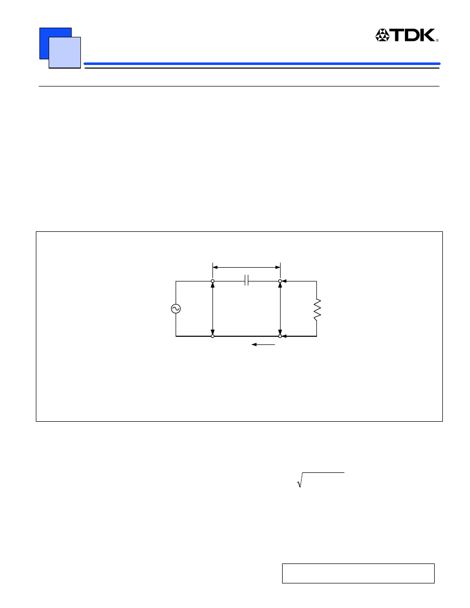
Capacitor Co is inserted in series with the CCFL in this circuit. This capacitor Co allows the output voltage from the
transformer to be applied directly to both electrodes of the CCFL before the start of the discharge (when the
impedance of the CCFL is infinity and there is no apparent load).
•
@
Load (before discharge starting)=
∞
Load (after discharge starting)=
Vout/ Iout
Before discharge starting :
Vout=Vopen, Vc=0
After discharge starting :
Vout=Lamp Voltage
Vc=Vout-Vl
Equivalent circuit of output
(lamp impedance)
V
c
C
o
V
open
V
out
R
L
I
out
Figure 5
After the discharge starts, the capacitor Co works as a current control device and the output current I
OUT
is determined
by the composite impedance of the capacitor Co and the equivalent load resistance R
L
of the CCFL.
Output current I
OUT
(
)
2
C
2
L
OUT
OUT
X
R
/
V
Z
/
V
−
=
=
(Reactance Xc = 1/
ω
C)
In the inverter circuit, we make the reactance component Xc of the capacitor Co larger than the equivalent load circuit
R
L
. This is because by making the Co component of the composite impedance larger, the output current I
OUT
is
determined by Co and the constant current characteristic, which is suitable for driving the CCFL, can be artificially
achieved. This Co is called the “ballast capacitor."
DC/ AC Inverter Unit for Liquid Crystal Display (LCD) Panel
DC-AC INVERTER UNIT
PAGE
6
APPLICATION NOTE
The frequency is determined by the parallel resonant circuit that consists of the push-pull combined inductance L
P
in
the primary side of the transformer, the resonant capacitor C
P
, and the total capacitance of Co that was translated to
the primary side from the ballast capacitor.
When the reactance component of the CCFL is ignored, the fundamental frequency is represented by the following
formula:
1
(2
π
√
L
P
(C
P
+ C
O
))
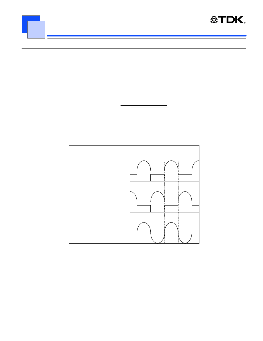
In order to maintain the resonance generated by the transformer and the capacitors, a feedback from the drive signal
base winding of the transformer is applied to the switching transistor. The base drive current is supplied through the
base resistor R from the input voltage by connecting the base winding N
B
. The oscillation is maintained by adjusting
the resonant frequency as shown in Figure 6 and by alternately turning ON Q1 and Q2.
By making the choke coil L two to three times larger compared with the primary winding L
P,
the input side will act as a
constant current source.
Q1 Collector
V
0
I
0
Q2 Collector
V
O
I
0
Oscillation waveform
Resonance
Capacitor
V
Figure 6
DC/ AC Inverter Unit for Liquid Crystal Display (LCD) Panel
DC-AC INVERTER UNIT
PAGE
7
APPLICATION NOTE
2.2 Precautions of implementation
1) Effect of the distributed capacitance
When high frequency backlighting is performed, the measurement values of evaluating the CCFL unit only and the
evaluation values in the system configuration will be different. The effect is especially significant when grounded
conductors exist in the vicinity of the wiring that connects the high voltage output terminal of the inverter and the
CCFL. This is because of the distributed capacitance around the high voltage.
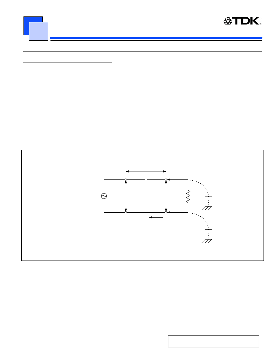
Figure 7 shows a conceptual model. When there is distributed capacitance the output voltage from the transformer is
divided by C
O
and C
G
after the CCFL starts. Brightness may be lower than that of the CCFL by itself because the
current drops by I
L
= Iout - I
G
while the lamp is lit. Therefore, it is necessary to make the high voltage lead wire as
short as possible and to make the distributed capacitance C
G
as small as possible. When a conductor is added along
the CCFL, however, it has the effect of lowering the starting voltage. This method is actually utilized in some designs.
Since it is difficult to describe the above usage in the form of specifications, testing using an actual system is
recommended.
•
@
Equivalent circuit of output
V
c
C
o
V
open
V
out
CCFL
I
out
C
G
C
G
I
G
I
G
Figure 7
2) Use environment
Unpredictable problems may occur depending on the application. For example, should the LCD system be used in a
food sales environment, moisture or solid contaminants may contaminate and short circuit the output terminals of the
inverter. Shorting the output can cause damage to the inverter. As the range of the applications of the LCD system
becomes wider, more accidents of this kind are possible. Care should be taken to check the conditions of the
application of the high voltage portion of any LCD backlighting system.

DC/ AC Inverter Unit for Liquid Crystal Display (LCD) Panel
DC-AC INVERTER UNIT
PAGE
8
APPLICATION NOTE
3) Safety standards
Since the inverter generates a high voltage, special care is required to prevent electric shock and the possibility of
fire. The inverter is designed with the assumption that it is built into a product and that there are no covers as the
ones used by ordinary power supplies. Therefore, caution should be exercised so that the inverter cannot be touched
directly. By adding a high voltage warning label and using an insulator sheet you can prevent accidental electric
shock during equipment repair. Even if an electric shock occurs, the circuit characteristics allow the electric current to
flow only at a level that has no harm to the human body, this is not considered to be a safety problem.
As a counter measure against heat and fire caused by a short circuit of the output or by component failure, a
protective device such as a fuse is used to cut the circuit. Flame retardant materials are used for the circuit boards
and resin materials in order to prevent the spread of fire. This is also required of the product in which the inverter is
built-in.
Since the PL (product liability) law came into force in July 1995, there has been a growing interest in making safe
designs. As official safety standards, each country has its own standards in addition to the international standard
IEC950. Two important points to consider are:
1) Ensuring the safety of the human body,
2) Ensuring the safety of the product and the surrounding objects.
Prevention of burns and electric shock are important for item 1. Spatial distance, distance from the surface, thickness
of the insulation, insulation resistance, degradation of the insulation materials, and the type of the insulation are
defined in regard to the electric shock that is related to the inverters.
There are four types of insulation; functional insulation, basic insulation, additional insulation, and enforced insulation.
Which type of insulation should be satisfactory depends on whether the following conditions apply or not:
l What is the product in which the inverter is used?
l Is it the primary circuit or the secondary circuit?
l Is it a current control circuit?
The inverter is usually used in office automation equipment such as laptop PCs and FAX machines, and it belongs to
the group class 1. The inverter is defined as a secondary circuit because it is not directly connected to the external
main power supply. Thus, the structure should satisfy the spatial and surface insulation of the functional insulation if it
is a specified current control circuit. Even if there is not enough room for the required distance, the IEC950 standard
[5.4.4] items b) and c) must be satisfied. (Refer to the applicable standard such as IEC and UL for the details of each
item.)
Item 2 requires the use of materials certified by UL standard (for example 94V-O) or equivalent for the organic
materials used in the transformer bobbin and the circuit boards, etc. It should be noted here that the safety standards
are the minimum standards to be followed, and there is no guarantee that there will not be any safety problem even if
these standards are met. In addition to the safety of the inverter by itself, it is also very important to check it in the
actual application.

DC/ AC Inverter Unit for Liquid Crystal Display (LCD) Panel
DC-AC INVERTER UNIT
PAGE
9
APPLICATION NOTE
3.0 Inverter for laptop PC’s
The inverters used in a laptop PC applications have some specific desirable features. Some of the most common are
discussed in this section.
A wide range of input voltages
Though the input voltage range varies depending on the specific battery used in each application, the inverter needs
to support battery voltages of approximately 5 to 15 V. When an AC adapter is used, however, even higher voltages
are present. In some cases, the input voltages range more than 4 to 1.
A wide range of brightness control
Since we assume portable use, the required brightness needs to be adjusted depending on the ambient environment.
Recently, the use of laptop PCs at home and in airplanes demands a stable illumination not only at a high brightness
but also at a low brightness.
Low power consumption
The efficiency of the inverter has a significant effect on the lifetime of the battery. It is necessary to use a circuit
configuration and components that consume as little power as possible. Although indirect, decreasing the intensity by
adjusting the brightness lowers the power consumption.
Small-size, narrow-shape
As the size of the screen becomes larger, the space for installing the inverter is getting tight. Not only thinner but
narrower inverters are demanded these days. Fewer components in the circuit and miniaturization not only contribute
to reducing the size of the unit but also to the reduction of the power consumption.
3.1 Wide range of input and the light control circuit
By adding a DC-DC converter circuit to the push-pull resonant circuit, dimming control over a wide range input
voltage becomes feasible. Figure 8 shows an example of a brightness control circuit that uses a control IC for a DC-
DC converter. In this method, the output current (CCFL current) from the inverter is detected by resistor R and used
as feedback to the DC/DC converter. Since the CCFL current is an AC current, the detected AC voltage is converted
to a DC value by an integration circuit then applied to the error amplifier of the control IC.
Output voltage at the CCFL can be varied by controlling the input voltage to the push-pull amplifier. Furthermore by
changing the output voltage of the DC-DC converter, the output current can be set to an arbitrary value for brightness
control. Since the feedback of the detected output current is compared with the reference voltage, the brightness is
controlled by changing the reference voltage. This scheme is sometimes referred to “brightness control by current.”
In order to achieve a wide range of brightness control, the discharge needs to be stable even when the CCFL current
is reduced. Low current through the CCFL can result in flickering and the discharge may be become unstable at low
temperatures.
DC/ AC Inverter Unit for Liquid Crystal Display (LCD) Panel
DC-AC INVERTER UNIT
PAGE
10
APPLICATION NOTE
DC/DC Converter
for Dimming
VR for Dimming
Lamp
Example of dimming control
Figure 8
The CCFL characteristics also have a significant effect on dimming range and it is necessary to select a CCFL that
can maintain a stable discharge under a low current condition. When the brightness control is reduced, the output
voltage of the inverter drops while the CCFL voltage increases. Thus the inverter needs to generate a voltage that
can maintain the CCFL voltage between both ends. In other words, the question is whether the output impedance and
the output voltage of the inverter are appropriate for the impedance and the voltage of the CCFL.
Another brightness control method is duty control. This method intermittently turns ON and OFF the input power to
the inverter to control the brightness by a duty ratio. In this method a wide dimming range of 10% to 100% can be
achieved. We can achieve this wide dimming range with this duty control method because the open circuit voltage
and the voltage applied to the CCFL does not drop when the duty cycle is reduced. However, a kind of stabilizer
circuit is required because the output voltage changes directly by the voltage drift of the input source such as a
battery. In addition, the frequency of the duty cycle control circuit is generally within the audible frequency range, and
the transformer or the coil might hum. Extra care must be taken with the transformer design.
3.2 Reducing power consumption
In order to reduce the power consumption, use of high performance switching devices, coils, and transformers are
required. Not only the efficiency of the power supply, but also the oscillator frequency and the waveform of the CCFL
current effect the efficiency of the light output with respect to the total input power. For example, while the waveform
of the primary side oscillator of the inverter is a sine wave, distortion can occur from the leakage of the transformer
and from the distributed capacitance when the CCFL is connected.
The relationship between the waveform and the brightness seems to show improvement in intensity as the CCFL
current waveform gets closer to a square wave. Therefore, it is necessary to examine the CCFL current and the
frequency while checking the luminance at the surface of the LCD panel.
DC/ AC Inverter Unit for Liquid Crystal Display (LCD) Panel
DC-AC INVERTER UNIT
PAGE
11
APPLICATION NOTE
The inverter transformer is one of the important components and EE type transformers with divided bobbins have
been proven to be an effective design. Molded and closed magnetic path style transformers that do not use a ballast
capacitor, have also been used successfully. Newly developed piezoelectric transformers made of ceramic materials
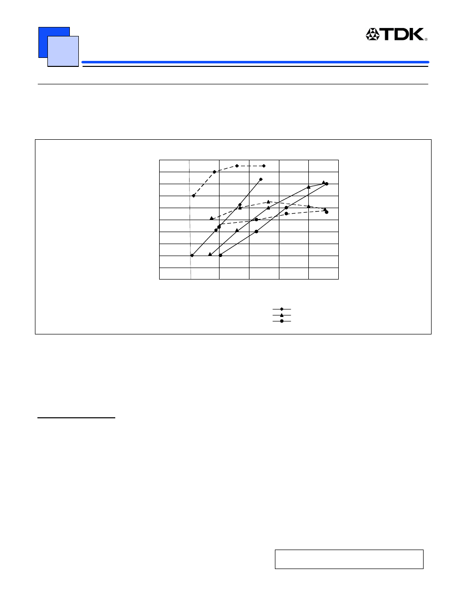
not only eliminate the ballast capacitor, but also achieve a high brightness efficiency as shown in figure 9.
Brightness characteristic by difference of transformer
Piezo Type A
Brightness Fl (cd/m*M)
Input Pin (W)
TDK CXA Series (2W Type)
(Input : Sine Wave)
45,000
50,000
0
0 . 5
1
40,000
35,000
30,000
25,000
20,000
15,000
10,000
5,000
‚1. 5
2Q..5
2
3
0
5,000
10,000
15,000
20,000
25,000
Piezo Type B
Eff Fl/Pin
Figure 9
Since piezoelectric transformers also have advantages in small size and low height, they are becoming increasingly
popular for use in inverters for laptop PCs. However, the driver circuit becomes complicated in order to boost the
voltage step up ratio and to maintain the output power to support larger panels. The cost of piezoelectric transformers
tends to be higher due to the materials and structure.
3.3 Miniaturization
Making inverters smaller and thinner is a common request. Components such as the coil, transformer, and
connectors are the key to miniaturization of the inverter. Once the required power is determined the physical shape is
dictated. Usually, a high voltage over 1000Vrms is required and the structure has to take into consideration the
insulation distance, this makes it more difficult to design the system including smaller and lower profile connectors.
In practice, it is very important to consider the mechanical layout of the system. The requirements of the custom
designed systems differ by each manufacturer. The shape of the panel, location of connectors, location of dimming
controls, and the shape of the circuit board all will effect the inverter design.

DC/ AC Inverter Unit for Liquid Crystal Display (LCD) Panel
DC-AC INVERTER UNIT
PAGE
12
APPLICATION NOTE
4.0 Inverters from TDK
The main TDK standard products are briefly explained here. TDK’s inverters fall into two basic categories:
l Non-dimming using a push-pull resonant circuit.
l Dimming control that has the added DC-DC converter.
Features of both types are discussed.
4.1 Standard products of the non-dimming type (PCB Mountable)
The non-dimming type is suitable for applications that do not require a variable brightness control. Typical
applications include industrial and general information displays as well as for initial evaluation of an LCD panel and
the reliability test of the LCD panel. The inverter is simple and inexpensive, therefore it is the best suited for
applications that simply illuminate the CCFL.
TDK recently added the “P” type inverter that includes a built-in circuit protection device in addition to the
conventional non-dimming circuit. The addition of this circuit protection further improves the safety of the inverter.
Generally, this type of inverter has an input voltage range of
±
5%. Because the output voltage and output current
change in proportion to the input voltage, small adjustment of the output current and the brightness can be easily
achieved by inserting a three terminal voltage regulator or a diode in the inverter’s input.
In some instances, when the input voltage is lowered, the open circuit voltage of the inverter becomes lower than the
starting voltage of the CCFL. In this case, an inverter that can generate a higher open circuit voltage is used. One
unit can drive one or two of CCFL’s and the output current setting can be set differently by four different kinds of
connection methods. With the exception of the CXA-P10x-P Series these inverters use a terminal pin construction
and are designed to be mounted directly to a PC board.
CXA-L10x-L Series
This model can be used for CCFL’s with a starting voltage of up to 900V. Two models with input voltages of 5V or
12V are available. The standard application is with two CCFL’s and an operating voltage of 450V and current of 5mA.
This series can handle a maximum of 4.5W.
CXA-M10x-L Series
This model can be used for CCFL’s with a starting voltage of up to 1200V. There are three models depending on the
input voltage; 5V, 12V, or 24V. The standard use is for two CCFL’s with a voltage of 600V and current of 5mA. This
series handles a maximum of 6W.
CXA-M14L-P
This model is a high-power type developed for very large LCD panels. This model can be used for CCFL’s with a
starting voltage of up to 1500V. The input voltage is 12V. The usage is for two CCFL’s with a voltage of 560V and a
current of 7mA. Maximum power is 8W. Up to 14-inch LCD backlight systems can be driven with this inverter.
CXA-P10x-P Series
This model can be used for CCFL’s with a starting voltage of up to 1500V. There are three models each with different
input voltages; 5V, 12V, or 24V. The standard application is for two CCFL’s with a voltage of 600V and current of
5ma. Maximum power of 6W.

DC/ AC Inverter Unit for Liquid Crystal Display (LCD) Panel
DC-AC INVERTER UNIT
PAGE
13
APPLICATION NOTE
4.2 Standard products of the non-dimming type (Connector I/O)
This series is similar in electrical design as the non-dimming type discussed above. The advantage of this series of
inverters is the addition of input and output connectors replacing the PC pins.
CXA-L05xx-NJL Series
This model can be used for CCFL’s with a starting voltage of up to 1500V. There are three models depending on the
input voltage; 5V, 12V, or 24V. The standard application is for two CCFL’s with operating voltages of 600V and
current of 5ma. Maximum power is 4 watts.
CXA-P1012-NJL
This model provides 7 watts of power and was specially developed for large panels. This model can be used for
CCFL’s with a starting voltage of up to 1500V. An input of 12 volts is currently available. The typical application is for
two CCFL’s with a voltage of 600V and current of 7mA. Up to a 14 inch LCD backlight system can be driven.
4.3 Standard products of the dimming control type
The products described below are inverter units with the addition of a dimming function utilizing a current feedback
method. The input voltage is wider making these products suitable for use in battery powered applications such as
laptop PCs and other portable equipment. In addition, modules for large LCD backlight systems have protection
circuits and alarm signal outputs so that they are suitable for industrial equipment and liquid crystal monitors which
require higher reliability. All of the dimming function type models have connectors for both input and output.
CXA-K0505-VJL
This inverter is used for driving one 2W-type CCFL and is capable of driving a color LCD panel of up to 8 inches.
Three types are available depending on the type of the output connector. The input voltage range is 5 to 12V, output
current is 2 to 5ma, and the dimming can be controlled by a 0 to 3V DC source.
CXA-L0612 Series
This inverter is used for driving one CCFL with a maximum power of 4W and is capable of driving a color LCD panel
of up to 13 inches. In addition to the three different types of output connector, two types of the output polarity are also
available making the CXA-L0612 series compatible with many different LCD panels. This makes a total of six types
that are commercially available. The input range is from 10 to 15V, the output current is 2 to 6ma, and they can be
used for CCFL’s with a voltage up to 600V or even higher. Therefore, this series can drive most of the popular LCD
panels that use one lamp. The dimming control method is the same as that of the CXA-K0512 series.
CXA-0190 (CXA-M1112-VJ)
This model was developed for industrial display equipment and LCD panels of up to 14 inches with two CCFL’s. It can
support a wide input voltage of 8 to 20V. Where high reliability is a requirement, features such as a thermal fuse and
an alarm function to indicate when the CCFL’s are approaching the end of life are desired. Both of these features are
included with this model. This model can support two CCFL’s with a voltage of 600V and a current of 5.5ma. This unit
provides a maximum of 7W. In addition, a cost reduced version that has a narrower input voltage of 12V
±
20% with
the same dimensions, CXA-0217 (CXA-P1212-VJL), will be commercially available shortly.
DC/ AC Inverter Unit for Liquid Crystal Display (LCD) Panel
DC-AC INVERTER UNIT
PAGE
14
APPLICATION NOTE
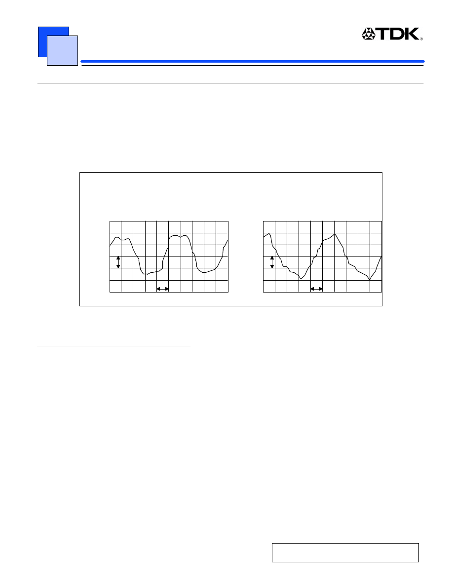
CXA-K0612 series
This is a new product currently under development. The shape is a narrow, 12 mm width, inverter in which TDK’s
ferrite technologies are utilized. The transformer is an 11mm wide slim transformer that can drive a CCFL with a
maximum open voltage of 1300V and power levels of up to 3W. This transformer has a special structure that uses a
U shape core. Though it’s only 11mm in width, the cross section of the core is large, to keep the efficiency high as
well as making the output current similar to the trapezoidal wave as shown in figure 10. Because of these features, it
has about 10% higher intensity for the same CCFL current compared with the conventional products.
Lamp current waveform
New Molded Transformer
5
5
Standard Transformer
5
5
Lamp: 2.6mm dia X 230mm Long
Lamp current: 6ma
Brightness F
L
: 4000cd/m
2
Lamp: 2.6mm dia X 230mm Long
Lamp current: 6ma
Brightness F
L
: 3600cd/m
2
I
out
I
out
u sec
u sec
Figure 10
4.3 Components used in the inverter
TDK’s manufactured inductors and capacitors, used in the design and manufacture of these inverters, are briefly
explained.
Inductors
Due to the good DC superimpose characteristics and low DC resistance, the TDK SLF series of surface mount, SMD,
style coils are suitable not only for the input of the inverter resonant circuit but also for use as the coil of the ordinary
step down DC-DC converter.
Capacitors
When using a closed magnetic path transformer, a smaller high voltage circuit with higher reliability can be
constructed by using a SMD high voltage capacitor such as a the TDK radial shape CC45 type or C4520 type.
In addition to setting the brightness control frequency and phase compensation of the control IC, multilayer capacitors
with capacitance’s higher than 1µF are used for filtering the input of the switching circuit.
Use of these TDK components allows further miniaturization and the ability to achieve a higher reliability CCFL
inverter.

DC/ AC Inverter Unit for Liquid Crystal Display (LCD) Panel
DC-AC INVERTER UNIT
PAGE
15
APPLICATION NOTE
5.0 Summary
A broad outline of the previous explanation regarding the use and selection of the inverters follows:
Deciding which display panel to use
↓
Deciding which cold cathode fluorescent lamp to use
↓
Understanding of the required characteristics of the CCFL
(Discharge starting voltage, operating voltage, current, frequency, etc.)
↓
Examining the conditions for implementation(Safety, distributed capacitance, etc.)
↓
Selecting the most suitable inverter.
Due to better image quality, larger size, and lower price, toward the year 2000 LCD panels will become more widely
used. Color displays are common now, and CCFL's that can emit a white light will be the mainstream of the LCD
backlight. Thus, high efficient inverters will be indispensable as their power supply.
The basics of the CCFL and the inverter are explained in this issue. When new technologies and new components
are developed, a clear definition of the application as well as the component selection for selecting and designing the
best inverter will be increasingly important in order to aim for a smaller size and higher efficiency.
TDK is designing the best inverters for typical LCD panels. Please feel contact us with your questions regarding our
line of standard or custom inverters, or the components we use.
Wyszukiwarka
Podobne podstrony:
Modified PWM Control for the DC AC Inverter With a Non Constant Voltage Source
Modified PWM Control for the DC AC Inverter With a Non Constant Voltage Source
A Study Of Series Resonant Dc Ac Inverter
DC AC inverter
A Study Of Series Resonant Dc Ac Inverter
Dc Ac Inverter Targets Electroluminescent Applications
Inverter controller for HVDC systems connected to weak AC sy
12V DC to 230V AC Inverter, 12v 230v inv
A Novel Switch Mode Dc To Ac Inverter With Nonlinear Robust Control
A Novel Switch mode DC to AC Inverter With Non linear Robust Control
A Novel Switch Mode Dc To Ac Inverter With Non Linear Robust Control
Dc To Ac Inverter With The 555
Inverter controller for HVDC systems connected to weak AC sy
A Novel Switch Mode Dc To Ac Inverter With Non Linear Robust Control(1)
03 Skompensowany przemiennik czestotliwosci AC DC AC
00329965 Quasi Parallel Resonant Dc Link Inverter With Improved Pwm Capability
09 Przetworniki AC DC i DC AC (2)
więcej podobnych podstron