
Initial Print Date: 12/04
Table of Contents
Subject
Page
Fuse Card . . . . . . . . . . . . . . . . . . . . . . . . . . . . . . . . . . . . . . . . . . . . . . . . . . .4
Main Fuse . . . . . . . . . . . . . . . . . . . . . . . . . . . . . . . . . . . . . . . . . . . . . . . . . . .5
Electronics Carrier . . . . . . . . . . . . . . . . . . . . . . . . . . . . . . . . . . . . . . . . . . . . . .5
Battery Safety Terminal . . . . . . . . . . . . . . . . . . . . . . . . . . . . . . . . . . . . . . . . . .6
Revision Date:
E46 Power Supply and Bus Systems

2
E46 Power Supply and Bus Systems
E46 Power Supply and Bus Systems
Model: E46
Production: From Start of Production
After completion of this module you will be able to:
• Understand the power supply systems in the E46
• Understand the Bus networks used in the E46
• Identify and Locate power supply components on the E46
E46 Power Supply
The power supply system in the E46 is used to supply power and ground to the various
components and systems. Some of the components include:
• Front power distribution box (fusebox)
• Battery and battery cables
• Grounding points
• Main fuse located in trunk
• Battery Safety Terminal
• Alternator (Generator)
Front Power Distribution
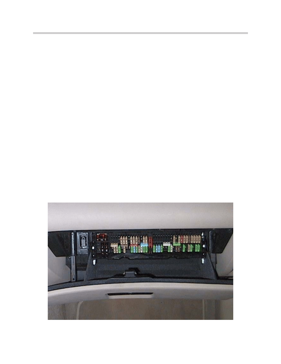
The main (front) fuse box is located behind the glovebox. The fuse panel is accessed by
rotating two twist locks 90 degrees and allowing the fuse panel to drop into view. The
fuse panel includes fuses 1-71.
There are also two large fuses (red 50 Amp) which provide power for the IHKA blower
and secondary air pump system.
Note: Always check the proper and most current ETM when checking fuses.
Due to optional equipment and production changes, some fuse numbers
and locations may vary.
3
E46 Power Supply and Bus Systems
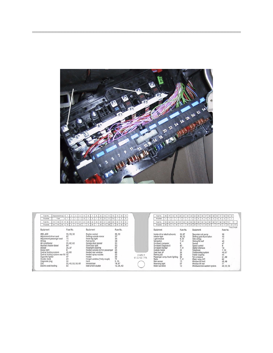
Located above the fuse panel, there are additional high amperage power distribution
fuses (F101-F107).
This location differs from the E38/E39 in which these high amperage fuses were located
under the front passenger carpet.
Fuse Card
There is also a fuse location card in the front fuse box to assist in locating various fuses.
4
E46 Power Supply and Bus Systems
Fuses F101-107
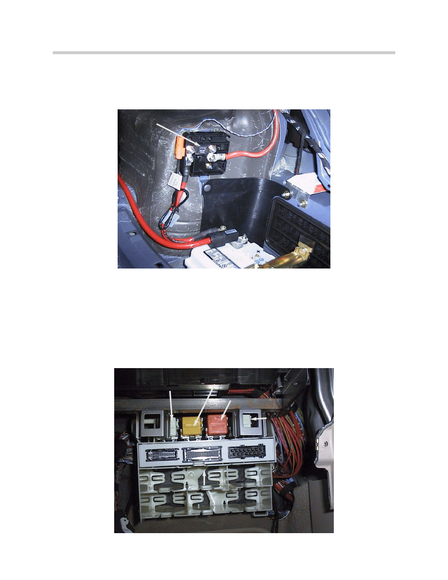
Main Fuse
The main fuse (F108) is located on the right hand side of the trunk, near the battery.
F108 is a 200 amp fuse which feeds the front power distribution box. F108 supplies
fuses F101-107 as well as F35-F71.
Electronics Carrier
The electronics carrier is located behind the glove box and contains various control mod-
ules and relay. Depending upon equipment levels and options, the carrier will contain dif-
ferent modules.
There are some modules and relays which will be present regardless of equipment.
these include the General Module, fuel pump relay, horn relay, foglight relay and the
blower relay for IHKA.
5
E46 Power Supply and Bus Systems
General Module
Fuel Pump Relay
Fuse 108 (Main)
Blower Relay
Fog Light Relay
Horn Relay
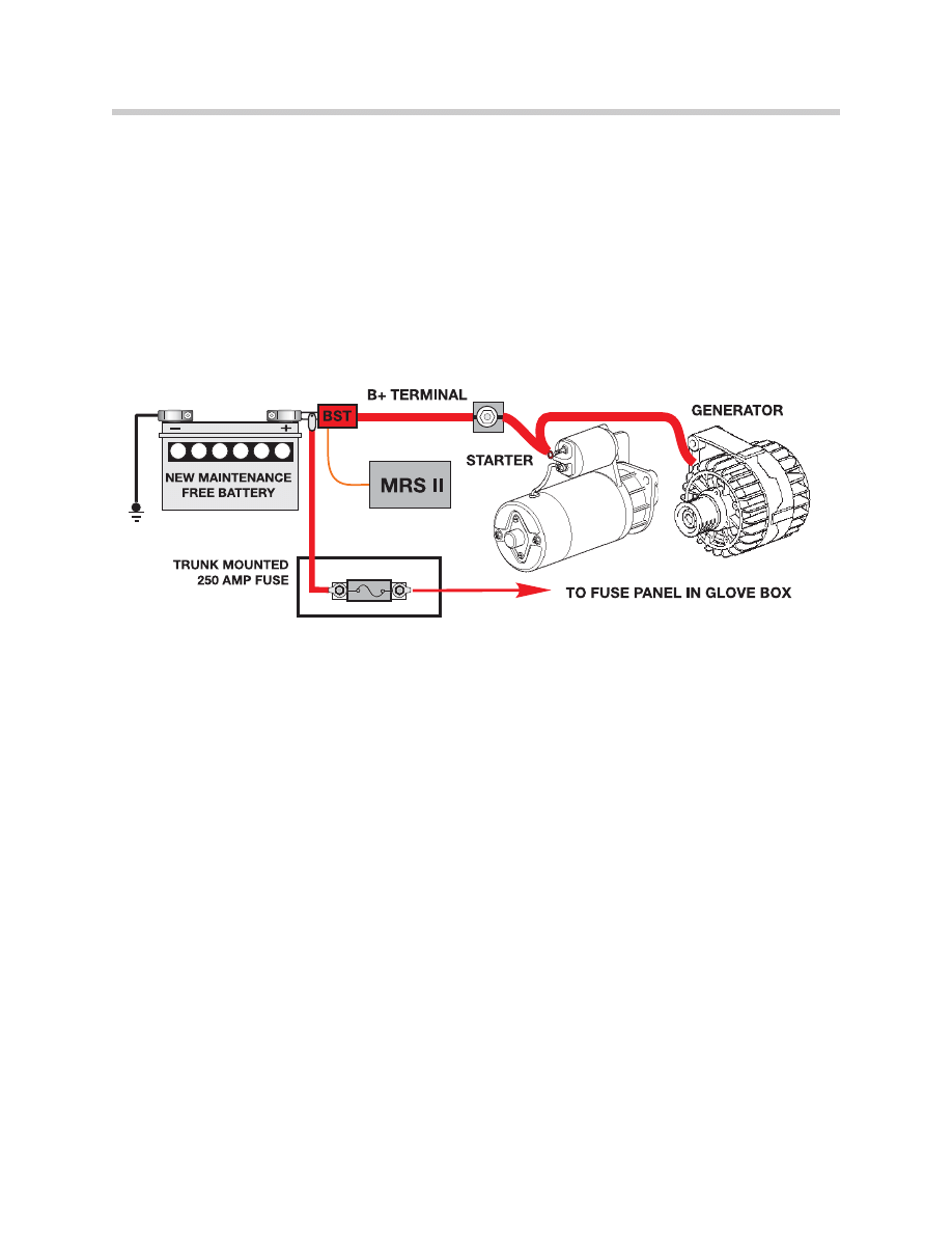
Battery Safety Terminal
The E46 uses a trunk mounted battery which has a (B+) battery cable than runs the
length of the vehicle. In the event of an accident, this cable could become compromised
and there is a possibility of short circuit to the vehicle body. In order to reduce this
possibility, the BST was added.
The BST is a pyrotechnic device which will disconnect the battery during an impact of
sufficient severity. Although the main battery cable will be disconnected, the connection
to the power distribution circuits will remain intact to allow other vehicle features to
remain operational (power windows, locks etc).
6
E46 Power Supply and Bus Systems
E46 Bus Systems
In comparison to the E36, the E46 was the first 3 series vehicle to make extensive use of
bus networks. The E46 benefitted from the latest bus technology which was introduced
previously on the E38 and E39.
The E46 bus network consists of the following busses:
• Diagnosis Bus (D-Bus)
• M-Bus
• Controller Area Network (CAN Bus)
• Body Bus (K-Bus)
• Local Interconnect Network (LIN bus) (From 2003)
7
E46 Power Supply and Bus Systems
A
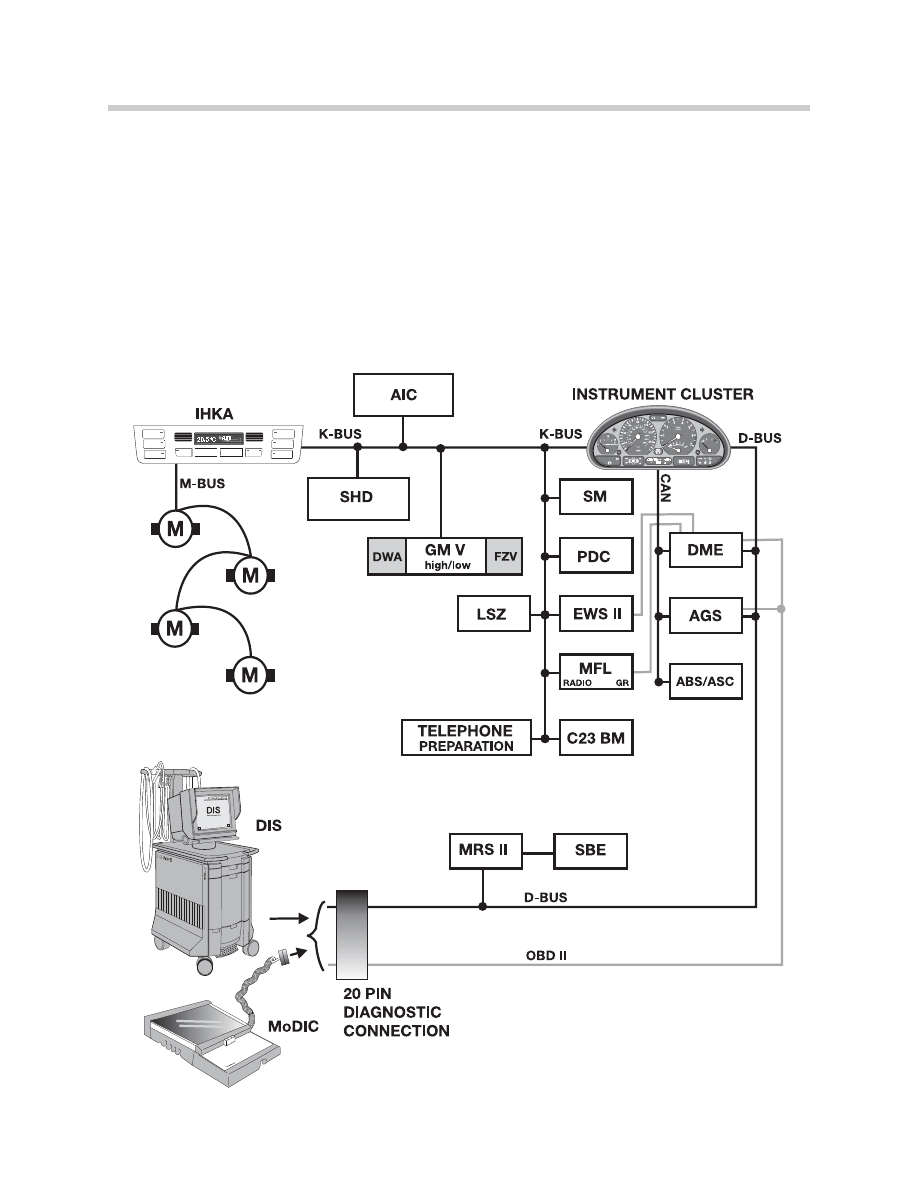
Diagnosis Bus (D-Bus)
The D-bus is used for diagnostic purposes, formerly referred to as TXD (RXD), this bus is
used as an interface between the diagnostic equipment (DISPlus/Gt-1) and the various
diagnoseable systems.
The D-Bus is directly connected to certain modules for diagnosis, however some
modules are diagnosed via a gateway. In the E46, the instrument cluster acts as a gate-
way between the D-Bus, CAN bus and K-Bus. For example, in order to read out fault
codes from the LSZ, the instrument cluster provides the gateway between the K-Bus and
D-bus.
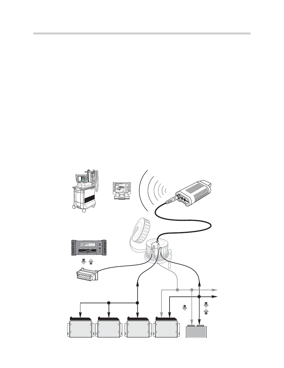
From start of production, the E46 was equipped with a 20-pin underhood diagnostic
connection as well as the required OBD II diagnostic connector (DLC). The OBD II
connector provided communication with the ECM (DME) and the EGS control modules
using aftermarket diagnostic equipment. To allow this communication, TXD II was added
as an dedicated connection. TXD II is identical to the D-bus, but is connected only to pin
17 of the OBD II connector and the ECM. The EGS communicates via CAN.
In model year 2001, the 20-pin diagnostic connector was deleted. BMW diagnostic
equipment now communicated exclusively through the 16-pin DLC.
8
E46 Power Supply and Bus Systems
RXD
TX
D
T
XD II
TXD II
T
XD II
T
XD II
RXD
TX
D
15
RXD
17
TXD II
2
7
OBD II DLC
(In Vehicle)
Scantools Communicate Via:
Pin 17 - TXD II only
(20 Pin Cap installed)
20
TXD
RXD
TXD
CONTROL
MODULE
TRANS
CONTROL
MODULE
ENGINE
CONTROL
MODULE
ABS/ASC
CONTROL
MODULE
EML
CONTROL
MODULE
20 Pin Diagnostic Connector
in engine compartment
Diagnostic Head
BMW Diagnosis and information system
Hassermen
Bsaljeoi
Gllufpjenr
Rusdljfoiv
TIS
Nerucvleu
Frluelkdmvdk
Wsdkurovcn
kjdfkjorir
Hassermen
or
GT-1
DIS Plus
Body Bus (K-Bus)
The K-Bus is used for the majority of systems on the E46. It differs from the I/K structure
used on the E38 and E39. The E46 does not use the I-Bus, but rather the K-Bus
exclusively.
The K-bus is a single wire network throughout the vehicle. The K-bus voltage is approxi-
mately 12 volts.
Controller Area Network (CAN Bus)
The CAN bus is a two wire bus used to allow communication between powertrain related
components and systems. The CAN network on the E46 uses a twisted pair configura-
tion which also uses two terminal resistors of 120 ohms each for a total circuit resistance
of 60 ohms.
M Bus
The M bus is used exclusively for the climate control system. The M bus allows the
IHKA/R control module to communicate with the various stepper motors for temperature
regulation and air flap control. There are 4 stepper motors used on the M-bus of the
E46.
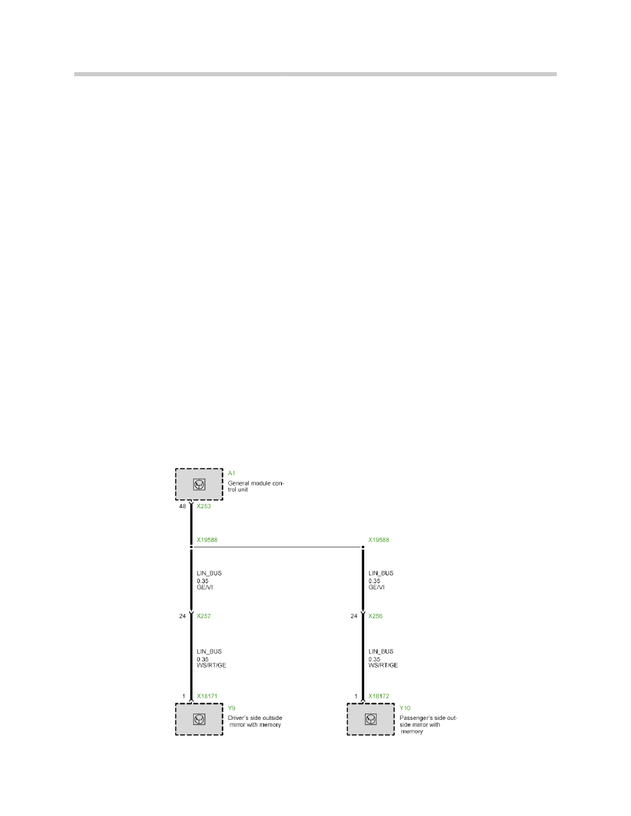
Local Interconnect Network (LIN Bus)
The LIN bus was not introduced on the E46 from start of production. The LIN bus was
added to the E46 from 2003 for Adaptive Headlights (AHL) and for side view mirror
control. The LIN bus consists of a single yellow/violet (GE/VI) wire.
9
E46 Power Supply and Bus Systems
LIN Bus (E46 mirrors)
Document Outline
- Main Menu
- Introduction to Bus Systems
- Power Supply and Bus Systems
- Instrument Cluster Electronics
- Base Instrument Cluster
- Lighting Systems
- Entertainment and Communication
- Vehicle Features
- Navigation Systems
- Central Body Electronics ZKE III
- E46 Power Supply and Bus Systems
- E46 Driver Information Systems
- E46 Lighting Systems
- E46 Entertainment Systems
- E46 Central Body Electronics
- E85 Power Supply and Bus Systems
- E85 Driver Information
- E85 Central Body Electronics
- E85 Info and Communication Systems
- E83 Electronic Systems
- Glossary
Wyszukiwarka
Podobne podstrony:
04a E85 Power Supply and Bus Systems
03 E70 Voltage Supply and Bus WB
Jvc Power Supply Description And Trouble Shooting Procedure
Battery Inverter For Modularly Structured Pv Power Supply Systems
Power Converters And Control Renewable Energy Systems
Control and Power Supply for Resistance Spot Welding (RSW)
[PhD 2003] Wind Power Modelling and Impact on Power System Dynamics
579393d1434286492 any interest e60 can bus code hacking 10 e60 voltage supply bus systems
[Engineering] Electrical Power and Energy Systems 1999 21 Dynamics Of Diesel And Wind Turbine Gene
ENERGY FOR BUILDINGS ESTIMATION OF DEMAND VARIATIONS AND MODERN SYSTEMS OF ENERGY SUPPLY Kalina 31
4 Fuel and Lubrication System
JOINT CAPABILITIES INTEGRATION AND DEVELOPMENT SYSTEM
Convert Computer ATX Power Supply to Lab Power Supply
M37a2 Heating and Ventilation System 18 32
Power Structure and Propoganda in Communist China
więcej podobnych podstron