
El 101
ACTA
POLYTECHNICA
SCANDINAVICA
ELECTRICAL ENGINEERING SERIES No. 101
Directly Driven, Low-Speed Permanent-Magnet Generators for
Wind Power Applications
PETRI LAMPOLA
Helsinki University of Technology
Laboratory of Electromechanics
P.O.Box 3000
FIN-02015 HUT
Finland
Dissertation for the degree of Doctor of Science in Technology to be presented with due permission of the Department
of Electrical Engineering, for public examination and depate in Auditorium S4 at Helsinki University of Technology
(Espoo, Finland) on the 29th of May, 2000, at 12 noon.
ESPOO 2000

2
Lampola, P., Directly Driven, Low-Speed Permanent-Magnet Generators for Wind Power
Applications. Acta Polytechnica Scandinavica, Electrical Engineering Series, No.101, Espoo,
2000, 62 p. (+106 p.). Published by the Finnish Academies of Technology.
ISBN 951-666-539-X. ISSN 0001-6845. UDC 621.313.8/.12:621.311.245.
Keywords: Permanent-magnet generator, gearless wind turbine, directly driven, low speed
ABSTRACT
The rotor of a typical wind turbine rotates at a speed of 20-200 rpm. In conventional wind
power plants the generator is coupled to the turbine via a gear so that it can typically rotate at a
speed of 1000 or 1500 rpm. The wind power plant can be simplified by eliminating the gear and by
using a low-speed generator, the rotor of which rotates at the same speed as the rotor of the turbine.
The hypothesis in this work is that the typical generator-gear solution in the wind power plant can
be replaced by a low-speed PM synchronous generator.
This thesis deals with the electromagnetic design and the optimisation of two types of low-
speed generators for gearless wind turbines. The generators designed are radial-flux permanent-
magnet synchronous machines excited by NdFeB magnets. The machines have different kinds of
stator windings. The first machine has a conventional three-phase, diamond winding. The second
machine has a three-phase, unconventional single-coil winding consisting of coils which are placed
in slots around every second tooth. The electromagnetic optimisation of the machine is done by the
finite element method and by a genetic algorithm combined with the finite element method. The
rated powers of the machines optimised are 500 kW, 10
kW and 5.5
kW. Two prototype machines
were built and tested.
The optimisation of the machines shows that the cost of active materials is smaller and the pull-
out torque per the cost of active materials higher in the conventional machines than in the single-
coil winding machines. The torque ripple can be reduced to a low level by choosing a suitable
magnet and stator slot shape in both the designs. The demagnetisation of permanent magnets is
easier to avoid in the single-coil winding machines than in the conventional designs. The
investigation of various rotor designs shows that the rotor equipped with curved surface-mounted
magnets has various advantages compared with the other rotor designs, for instance pole shoe
versions. The analysis of the machines also shows that the load capacity of the machine is lower in
a diode rectifier load than that when connected directly to a sinusoidal grid.
According to the analysis, a typical generator-gear solution of the wind power plant can be
replaced by a multipole radial-flux PM synchronous machine. The conventional diamond winding
machine is a better choice for the design of a directly driven wind turbine generator but the single-
coil winding machine is also suitable because of its simplicity.
All rights reserved. No part of the publication may be reproduced, stored in a retrieval system, or
transmitted, in any form or by any means, electronic, mechanical, photocopying, recording, or
otherwise, without prior written permission of the author.

3
PREFACE
This research was accomplished in the Laboratory of Electromechanics, Helsinki University of
Technology, Finland. The work is applied to the design and the optimisation of directly driven,
low-speed generators for wind power applications.
I would like to express gratitude to my supervisor, Professor Tapani Jokinen, Head of the
Laboratory of Electromechanics, Helsinki University of Technology, for his support and
encouraging attitude to my work.
Special thanks are reserved for Professor Jorma Luomi. I am grateful that it has been possible to
stay at the Department of Electrical Machines and Power Electronics, Chalmers University of
Technology, Sweden, during the period February - July 1994. I would also like to thank him for his
good advice on academic writing.
Further I would like to thank Mr Jarmo Perho, Dr Juhani Tellinen, Dr Antero Arkkio, Dr Janne
Väänänen, Dr Sakari Palko and Dr Juha Saari, for the interesting and successful co-operation in the
field of computation, electrical machines and wind power plants. I would like to thank Mr Pertti
Saransaari and Mr Jouko Virta from KCI Motors Corporation for interest in my project and for
manufacturing the prototype machine. I also wish to thank the members of the laboratory staff for
helpful discussions and advice as well as an enjoyable atmosphere to work in.
I sincerely appreciate the financial support for this project from the Helsinki University of
Technology, the Graduate School of Electrical Engineering, the Electric Engineers Foundation's
ABB-Strömberg Fund and the Foundation of Technology in Finland.
Finally, I would like to dedicate this thesis to my wife Annikka, who during these years has
shown understanding and support despite the long working hours.
Espoo, March 2000
Petri Lampola

4
CONTENTS
Preface
3
List of publications
5
The author's contribution
6
List of symbols
7
1 Introduction
9
1.1 Wind power plants
9
1.2 Overview of directly driven wind generators
11
1.2.1 Radial-flux generators with field winding
11
1.2.2 Axial-flux permanent-magnet generators
11
1.2.3 Radial-flux permanent-magnet generators
13
1.2.4 Special generators
16
1.2.5 Comparison of directly driven generators
17
1.2.6 Summary of directly driven generators
19
1.3 Aim of this work
19
1.4 Contents of the publications
20
2 Methods
21
2.1 Finite element method
21
2.2 Genetic optimisation
22
3 Design of low-speed radial-flux permanent-magnet synchronous machines
25
3.1 Background of the design
25
3.2 Background of the optimisation
27
3.3 Conventional PM synchronous machines
29
3.3.1 Machine topology
29
3.3.2 Design of the machines
30
3.3.3 Machines with a diode rectifier load
31
3.3.4 Comparison of different rotor designs
33
3.3.5 Experimental machine
36
3.4 Single-coil winding PM synchronous machines
38
3.4.1 Machine topology
38
3.4.2 Design of the machines
39
3.4.3 Experimental machine
40
3.5 Comparison of the PM machines
42
4 Discussion
45
4.1 Wind generators
45
4.2 Optimisation method
45
4.3 Electromagnetic characteristics of the machines
48
4.4 Demagnetisation of the magnets
49
4.5 Gearless and geared solutions
50
5 Conclusions
53
References
55
Appendix: Laboratory set-up
61

5
LIST OF PUBLICATIONS
The thesis consists of the overview and the following publications.
1.
Lampola, P., Saari, J., Perho, J. 1997: "Electromagnetic Design of a Low-Speed Surface-
Mounted Permanent-Magnet Wind Generator," Electromotion, 1997, Vol.4, No.4, pp. 147-
154.
2. Lampola, P., Perho, J., Väänänen, J. 1996: "Analysis of a Low-Speed Permanent-Magnet Wind
Generator Connected to a Frequency Converter," In Proceedings of the International
Conference on Electrical Machines (ICEM'96), Vigo, Spain, 10-12 September, 1996, Vol. 2,
pp. 393-398
3. Lampola, P., Perho, J., Väänänen, J. 1996: "Analysis of a Low-Speed Permanent-Magnet Wind
Generator," In Proceedings of the European Union Wind Energy Conference and Exhibition,
Gšteborg, Sweden, 20-24 May, 1996, pp. 500-503.
4.
Lampola, P. 1996: "Losses in a Directly Driven, Low-Speed Permanent-Magnet Wind
Generator," In Proceedings of the Nordic Research Symposium on Energy Efficient Electric
Motors and Drives, Skagen, Denmark, 12-16 August, 1996, pp. 358-364.
5.
Lampola, P. 1999: "Optimisation of Low-Speed Permanent-Magnet Synchronous Machines
with Different Rotor Designs," Electromotion, 1999, Vol.6, No.4, pp. 147-159.
6.
Lampola, P., Tellinen, J. 1997: "Directly Driven Permanent-Magnet Generator for Wind Power
Applications," In Proceedings of the European Wind Energy Conference (EWEC'97), Dublin,
Ireland, 5-9 October, 1997, pp. 698-701.
7.
Lampola, P. 1998: "Electromagnetic Design of an Unconventional Directly Driven Permanent-
Magnet Wind Generator," In Proceedings of the International Conference on Electrical
Machines (ICEM'98), Istanbul, Turkey, 2-4 September, 1998, Vol. 3, pp. 1705-1710.
8.
Tellinen, J., Lampola, P., Jokinen, T. 1996: "Low-Speed Permanent Magnet Machine with
High-Torque Capacity," In Proceedings of the Second International Scientific and Technical
Conference on Unconventional Electromechanical and Electrotechnical Systems (UEES'96),
Szczecin, Poland, 15-17 December, 1996, Vol. 2, pp. 377-382.
9.
Lampola, P. 1999: "Low-Speed Permanent-Magnet Generators for Gearless Wind Turbines,"
Helsinki University of Technology, Laboratory of Electromechanics, Report, No. 62, Espoo,
Finland, 2000, 24 p. Submitted to European Transactions on Electrical Power (ETEP) July 12,
1999.
10. Lampola, P. 1999: "Optimisation of a Directly Driven, Low-Speed Permanent-Magnet Wind
Generator," In Proceedings of the Fourth International Scientific and Technical Conference on
Unconventional Electromechanical and Electrotechnical Systems (UEES'98), St. Petersburg,
Russia, 21-24 June, 1999, Vol. 3, pp. 1147-1152.

6
THE AUTHOR'S CONTRIBUTION
The author has had an active role at all stages of the work reported in the publications. The author
has written the publications [1-7, 9-10], except for the thermal part in publication [1], which was
written by Juha Saari. In publication [8] the author has written the part about the low-speed
generator.

7
LIST OF SYMBOLS
a
i
Experimental coefficient
A
s
Area of the conductive region in a stator slot
b
Magnet width per pole pitch
b
m
Magnet width
b
s
Stator slot width
B
min
Minimum flux density in permanent magnets
B
r
Remanence of the magnets
B
r
Radial component of the air-gap flux density
B
ϕ
Tangential component of the air-gap flux density
C
Machine constant
Cost
Cost of active material
d
Air-gap diameter
E
Induced voltage
H
c
Coercivity of the magnets
l
Length of the stator and rotor cores
l
b
Length of the winding overhang
L
d
Inductance
L
1
, L
2
Load inductance
n
Rated speed
N
c
Number of conductors in series in a stator slot
p
Number of pole pairs
q
Number of slots per pole and phase
r
r
Inner radii of the air gap
r
s
Outer radii of the air gap
R
s
, R
k
Stator resistance
R
L
, R
L1
, R
L2
Load resistance
S
ag
Cross-sectional area of the air gap
T
Torque
T
cog
Cogging torque
T
max
, T
m
Pull-out torque
T
n
Rated air-gap torque
U
Line to line voltage
U
ind
Induced voltage
U
1f
, U
2f
, U
3f
Phase voltage
x
d
Per unit synchronous reactance
X
b
End-winding reactance
z
Q
Number of conductors in a stator slot

8
τ
m
Magnet width per pole pitch
τ
p
,
τ
Pole pitch
τ
r
Pole pitch of the rotor
µ
0
Vacuum
permeability
σ
Conductivity
ω
Electrical angular frequency
ω
m
Mechanical angular frequency
ψ
m
Peak flux linkage of the phase winding
Abbreviations
DC
Direct current
FEM
Finite element method
HTF
Harmonic voltage factor [IEC-34-1]
NdFeB
Neodymium-Iron-Boron permanent magnets
PM
Permanent magnet
PS-1
Machine with rectangular magnets equipped with pole shoes, constant air-gap
length
PS-2
Machine with rectangular magnets equipped with pole shoes, air-gap length
varies
RM-1
Machine with rectangular surface-mounted magnets, one magnet per pole
RM-3
Machine with rectangular surface-mounted magnets, three parallel magnets
per pole
SM
Machine with curved surface-mounted magnets
UC
Machine with unconventional single-coil winding
9
1
INTRODUCTION
1.1
Wind Power Plants
Wind turbines are widely used as a pollution free and renewable source to supplement other
electricity generation. Wind power technology has been developed remarkably during the latest
decade. The real cost of energy from wind turbines is falling dramatically. Nowadays more than
10000 MW wind power capacity has been installed world-wide. The installed capacity will be 37
MW including 63 wind turbines in Finland at the end of 1999. The machines now entering the
market generate 300–1500 kW per turbine rather than the 100 kW average of the late eightie
models. This upscaling is foreseen to continue at least one step more to a 4–6 MW offshore turbine.
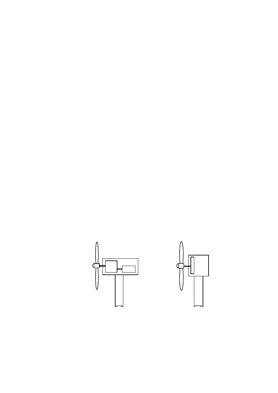
A present day typical and a new directly driven wind power plant are illustrated in Fig. 1. The
electromechanical system of a wind power plant usually consists of three main parts: turbine,
gearbox and generator. The rotor of a typical wind turbine rotates at a speed of 20–200 rpm. In
conventional wind power plants, the generator rotational speed is usually 1000 or 1500 rpm. This
means that a gear is needed between the turbine and the generator. A standard asynchronous
generator can be used in conventional wind power plants. The constant speed operation is
commonly used in this type of the wind turbine. The generator can be connected directly to the
grid, which results in a simple electrical system. However, the gearbox adds to the weight,
generates noise, demands regular maintenance and increases losses. The maintenance of the
gearbox-generator system may be difficult, because the nacelle is located at the top of the tower.
Furthermore, there may also be problems with materials, lubrication and bearing seals in cold
climates.
40 rpm
GEAR
1:37.5
1500 rpm
GEN.
GEN.
40 rpm
40 rpm
Figure 1. Typical and directly driven wind power plants.
The wind power plant can be simplified by eliminating the gear and by using a low-speed
generator the rotor of which rotates at the same speed as the rotor of the turbine. Many
disadvantages can also be avoided in gearless wind turbines. The noise caused mainly by a high
rotational speed can be reduced. The advantages are also high overall efficiency and reliability,
reduced weight and diminished need for maintenance. However, the diameter of a low-speed

10
generator may be rather large because a great number of poles is needed in a low-speed machine.
Due to the multipole structure, the total length of the magnetic path is short. The winding
overhangs can also be shorter and stator resistive losses lower than those in a long pole pitch
machine. The output frequency is usually lower than 50 Hz, and a frequency converter is usually
needed in low-speed applications. The converter makes it possible to use the machines in variable
speed operation. The speed can be variable over a relatively wide range depending on the wind
conditions, and the wind turbines can extract maximum power at different wind speeds. The
advantages of the variable speed operation are, for instance, the reduction of the drive train,
mechanical stresses, the improved output power quality and the increased energy capture.
The main data of the commercial gearless and geared 500 kW wind turbines are given in
Table 1. The gearless turbine has variable-speed operation and the geared turbines have constant
speed operation. The average price for large, modern wind turbines is around 1000 EUR per
kilowatt electrical power installed. The annual energy production is higher and the total weight of
the rotor and nacelle lower in the gearless turbine than the average values in the geared turbines.
The data of a typical 500 kW generator-gear solution are shown in Table 2. The generator is a four
-
pole induction machine. The gear is a combined planetary and parallel stage design: planetary in the
first stage and parallel in the second and third stages. The gear contains the main shaft bearing and
the gear ratio is 50.
Table 1. Main data of the commercial 500 kW wind turbines [Anon. 1996].
Wind turbine
A
Gearless
B
Gear
C
Gear
D
Gear
E
Gear
F
Gear
Average
B-F
Diff. [%]
(B-F)/A
Output [kW]
Speed [rpm]
- Rotor
- Generator
Energy prod. at mean
wind speed [kWh/a]
- 5 m/s
- 10 m/s
Tower height [m]
Rotor diameter [m]
Weight [1000 kg]
- Rotor, incl. hub
- Nacelle
- Rotor + nacelle
- Tower
- Total
500
18-38
18-38
615
2350
42
40.3
20.5
5.6
26.1
34.0
60.1
500
32
1500
588
2120
39
40.8
12.0
22.0
34.0
30.5
64.5
500
30
1500
505
2196
33.8
37
8.8
18.0
26.8
23.2
50.0
500
30
1500
543
2281
40
39
6.7
17.3
24.0
28.5
52.5
150/500
30
1000/
1500
513
2203
40
37
8.5
20.5
29.0
30.0
59.0
500
30
1500
491
2145
40
37
9.8
21.5
31.3
27.0
58.3
500
30.4
1500
528
2189
38.6
38.2
9.2
19.9
29.0
27.8
56.9
-14
-7
-8
-5
-55
+255
+11
-18
-5
Table 2. Main data of a typical 500 kW generator-gear solution [Anon. 1995-2000].
Weight [kg]
Efficiency [%]
Gear
Induction generator
Total
5100
2900
8000
98.0
95.6
93.7

11
The developments of wind turbines are moving in the direction of larger and well-optimised
units. The gearless design with a low-speed generator is a promising concept for wind turbines. The
number of moving components can be reduced by using a directly driven generator.
1.2
Overview of Directly Driven Wind Generators
There are different alternatives for the design of a directly driven generator. It can be, for
example, an asynchronous machine, a permanent-magnet synchronous machine or a synchronous
machine excited by a traditional field winding. Furthermore, the machine can be a radial-, an axial-
or a transverse-flux machine. The stator core can be slotted or slotless, and there can, for example,
be a toroidal stator winding in an axial-flux machine. Many different generators have been
proposed in the literature as directly driven wind-turbine generators.
1.2.1
Generators with Field Winding
A radial-flux synchronous machine excited by a traditional field winding is one alternative for
making a directly driven wind generator. The diameter of the machine in a large wind power plant
will be large and the length small. The pole pitch must be large enough in order to arrange space for
the excitation windings and pole shoes. The frequency must usually be lower than 50 Hz, typically
10–20 Hz, and a frequency converter is needed. The generator can be directly connected to a simple
and cheap diode rectifier. However, the machine demands regular maintenance.
The first commercial directly driven generator in the power range of some hundreds of kilowatts
is a synchronous machine excited by a traditional field winding [Anon. 1996]. The first prototype
was built in 1992. The outer diameter of the 500 kW generator is about 5 metres and the length
0.6 metre. The wind power plant is designed to be used with a frequency converter and the roto
rotational speed varies between 18–38 rpm. Nowadays, this type of 200 kW – 1.5 MW gearl
turbine is on the market [Anon. 1999a, 1999b]. However, the designs of the generators have not
been presented in detail.
1.2.2
Axial-Flux Permanent-Magnet Generators
Today, most of the low-speed wind-turbine generators presented are permanent-magnet (PM)
machines. The characteristics of permanent-magnet materials are improving and the material prices
are decreasing. PM generators are usually axial- or radial-flux machines. The axial-flux machines
usually have slotless air-gap windings. A design without slots simplifies the winding design. The
magnets used can be of a flat shape, which is easy to manufacture. The length of the axial-flux

12
machine is short compared to the radial-flux machine. Many axial-flux machines can easily be
connected directly to the same shaft. The machine may have high axial force between the stator and
rotor discs. Practical problems may arise in maintaining a small air gap in a large diameter machine
and the structural stability of the large diameter discs.
Many papers have been written on axial-flux PM generators. Chalmers et al. [1997] have
presented an axial-flux slotless machine with a toroidal air-gap winding. More magnet material is
needed in a slotless machine than in a slotted machine, because the total air gap (air gap + winding
thickness) is large. On the other hand, the increased air-gap length reduces the effect of
demagnetising field. In the slotless machine the cogging torque can be completely avoided, that
also decreases noise. A skewed construction of the stator or rotor is unnecessary in this type of a
machine. However, eddy-currents are induced in the winding by the main air-gap flux. A 1.5 kW,
24 pole as well as a larger 5 kW experimental machine have been built. The machines are for use in
small-scale stand-alone generating systems in remote areas. The reduction of the cost of high-
energy permanent-magnet materials is expected to open up applications for the axial-flux machines.
An axial-flux machine with toroidal air-gap winding has also been presented by Söderlund et al.
[1996]. NdFeB permanent magnets are mounted on two rotor discs on both sides of the stator. A
5 kW and a 10 kW experimental machine have been built and tested. The machines have 14 poles.
Special attention must be paid to the choice of structural materials. If the casing is too close to the
rotating magnets, the leakage flux will induce eddy currents causing extra losses and heating. A
100 kW, 90 pole experimental machine is under construction.
Stiebler and Okla [1992] have presented design aspects for an axial-flux machine with toroidal
air-gap winding. A 2.7 kW, 18 pole experimental machine has been built and tested. The measured
results have indicated a good agreement with the predicted results.
A toroidal-stator axial-flux machine has also been presented by Caricchi et al. [1992]. A 16 pole
experimental machine of 1.3 kW has been built and tested. A 5 kW, 24 pole generator to be
installed in the extremely cold climate in Antarctica has also been proposed by Caricchi et al.
[1999]. The field test includes monitoring of generator and power converter significant quantities as
well as tuning of the control algorithm for optimisation of the wind generator power-speed
characteristic. An example of a 1 MW, 60 pole machine has been presented by Honorati et al.
[1991]. However, the rated speed is 100 rpm, which is rather high in such a large wind turbine.
Muljadi et al. [1999] have proposed a modular axial-flux PM generator. The machine has two
stators - one on each side of the rotor. The machine has a toroidal stator winding located in open
stator slots. The modular concept was designed for the commercial production of the machines with
different sizes and output requirements. A small 18 pole single-phase machine has been built. The
efficiency of the machine is only 75% because of high leakage and core losses. The geometry of the
machine was not optimised, because the project focuses on the proof of the concept.
An axial-flux generator, in which two stators are sandwiched between three rotor discs has been
presented by Alatalo and Svensson [1993]. The rated power of the generator designed is 235 kW

13
and the number of poles 100. A 4.7 kW, 12 pole double-stator axial-flux experimental machine has
been built. The machines have air-gap windings.
Most of the axial-flux machines presented have an air-gap winding and surface-mounted
magnets. The advantages of the axial-flux machine are: low cogging torque and noise, small length
of the machine and the fact that many machines can be mechanically connected with each other.
The disadvantages are the need for a large outer diameter of the machine, structural instability of
the large diameter discs, and large amount of magnet material in the slotless design. The output of
the experimental machines is in most cases rather low, only some kilowatts, but a 100 kW machine
is also under construction.
1.2.3
Radial-Flux Permanent-Magnet Generators
Radial-flux PM generators may be divided into two main types, surface-magnet and buried-
magnet machines. The simple way to construct a rotor having a great number of poles is to mount
the magnets onto the surface of a rotor core. However, it is necessary to use high-energy magnets
such as NdFeB magnets to provide an acceptable flux density in the air gap. The high-energy
magnets are very expensive and the magnet material should be used effectively. Furthermore, the
surface-mounted magnets should be mechanically protected by a band surrounding the rotor.
Cheaper ferrite magnet material can be used in a buried-magnet machine. The cost of the magnet
material is relatively low but the assembly is complicated and costly. More magnet material is
needed in a machine with ferrite magnets than in a machine with rare-earth magnets and, therefore,
the weight of the rotor becomes rather high.
Many papers have been written on radial-flux PM generators. Spooner and Williamson [1996]
have proposed generators excited by buried ferrite magnets and surface-mounted NdFeB magnets.
The machines have a fractional slot winding and the number of stator slots per pole and phase, q, is
less than one. The machines can be designed with a small pole pitch and diameter, if permanent-
magnet excitation is used. Two experimental machines of a few kilowatts have been built. The
machines have 16 poles and the number of stator slots per pole and phase, q is 3/4. The machines
generated an almost sinusoidal terminal voltage, whilst the voltage induced in individual coils
contained significant harmonics components. The larger experimental machine of surface-mounted
magnets has 26 poles and q is 5/13. With so few slots, the subharmonic field was prominent and it
may lead to additional losses. A 400 kW, 166 pole machine has also been designed. The efficiency
was maintained at a high value over a very wide range of operating power.
Grauers [1996a, 1996b, 1996c] has optimised analytically a surface-mounted PM generator with
a simplified cost function, which includes the cost of active parts, structure and average losses. The
generator type from 30 kW up to 3 MW is investigated, and it is more efficient than a convention
induction generator with a gear. The active weight per rated output and total cost per rated output
are about the same for all the generator sizes. The outer diameters of the directly driven generators

14
are only slightly larger than the width of conventional wind turbine nacelles. Compared with other
directly driven generators, the proposed generator type is small. It is much smaller than the
electrically excited generator, the axial-flux generator and the direct grid-connected radial-flux
generator. It is of about the same size as the transverse-flux generator with a diode rectifier. The
reason for the small size is mainly that a high pull-out torque is not required, because the generator
is connected to a forced commutated rectifier. The efficiency at rated load is similar for all the
alternatives in the comparison. Furthermore, Grauers et al. [1997] have built a 20 kW, 66 pole
surface-magnet machine excited by NdFeB magnets. The system of a PM generator and a
frequency converter had a good performance and high efficiency.
Kladas et al. [1998] and Papathanassiou et al. [1999] have proposed a generator excited by
buried and surface-mounted magnets. 20 kW, 50 pole machines with q=1 have been designed. The
machines were first designed analytically and then by the finite element method in order to
investigate the optimal shape of the permanent magnets. According to the results, the torque ripple
of the surface-magnet machine was lower than that of the buried-magnet machine. A thin magnet
configuration with sufficient magnet width provides high torque per magnet volume. However, this
magnet geometry involves a risk of demagnetisation of the magnets.
Yildirim et al. [1998] have presented test results of a drive system of a directly driven wind
power plant. The 20 kW, 12 pole generator used has surface-mounted NdFeB magnets and the
number of stator slots per pole and phase is two. The harmonic content of the line current of the
machine is over 10%. The characteristics and the design of the generator have not been presented in
detail.
Lampola [1995, 1996, 1999a–c] and Lampola et al. [1995, 1996a–b, 1997] have proposed
surface-magnet generators excited by NdFeB magnets. 500 kW, 10 kW and 5.5 kW machines have
been optimised using a genetic algorithm combined with the finite element method. A 10 kW
prototype machine has 12 poles and q is 1.5. The results of the research are presented in more detail
in this thesis.
Chen et al. [1998] have proposed an outer rotor generator, where the position of the stator and
the rotor are exchanged. The machine has surface-mounted NdFeB magnets. While the generator is
running, the centrifugal force of the magnets applies pressure to the outer rotor core. Thus, the
reliability of the glued joints becomes higher. On the other hand, the stator winding may be difficult
to locate in the inner stator with a small diameter, because the slot pitch and pole pitch should be
large enough. A simple magnetic equivalent circuit approach was designed for the outer rotor
design. The design principles were used for initial design iteration and FEM was applied to analyse
the detailed characteristics. A 20 kW, 48 pole machine with q=1 has been built. It is verified that a
PM generator made in such a simple construction can operate with good and reliable performance
over a wide range of speeds. The design of the generator was not presented in detail.
Rasmussen et al. [1993] have proposed an outer rotor generator having buried ferrite magnets.
The rotor has salient poles with pole shoes and permanent magnets placed in between the poles
instead of the traditional DC excitation coils. According to the results, the pole pitch is nearly

15
constant independent of the generator size. In practice, it is between 30 mm and 50 mm for th
power range from 1 kW to 500 kW. The numbers of stator slots used are 3 to 4 per pole pitch.
20 kW, 90 pole and a 100 kW, 130 pole machine have been built.
Radial-flux PM generators with special stator design have been proposed by Spooner et al.
[Spooner et al. 1996, Spooner and Williamson 1998]. The machines have a winding consisting of
coils which are placed in slots around every second tooth, i.e. a single-coil winding. The machine
design is modular. The stator modules consist of an E-core with a single coil producing a single-
phase AC output. The module outputs are to be rectified separately and combined at a common DC
link. The rotor modules use standard ferrite magnet blocks. The modules can be used for a wide
range of machine designs. A small 26 pole prototype machine consisting of 26 rotor and 15 stator
modules has been built. Designs for a 400 kW, 166 pole and 1 MW, 150 pole machine have bee
presented. The outer diameter of the 1 MW machine is about 4 m and the length 0.6 m. Additio
loss mechanisms peculiar to the modular arrangements have been identified. For example, the rotor
eddy-current losses were the dominant parasitic losses and required the redesign of the rotor
modules based on laminated flux concentrators.
Carlson et al. [1999] have presented test results of a 40 kW, 48 pole experimental machine o
the above mentioned design. The machine is a pilot scale test unit of a 500 kW machine. They
showed that a wind turbine system with a directly driven, low-speed PM generator and a frequency
converter is well suited for up-scaling today's commercial sized wind turbines.
The single-coil winding machine has also been presented by Tellinen and Jokinen [1996],
Tellinen et al. [1996], Lampola and Tellinen [1997] and Lampola [1998, 1999c]. The machine has a
three-phase winding and the excitation of the machine is made by surface-mounted NdFeB
magnets. The number of stator slots per pole and phase is low and, therefore, the diameter of the
machine can be small. A 6 kW, 40 pole prototype machine has been presented. The rotor is divided
in the axial direction into three slices, which have been rotated with respect to each other. As a
result of this splitting, the magnets have been skewed with respect to the stator slots. The proper
choice of permanent magnet width and a three-slice rotor structure reduced noticeably the torque
ripple of the machine. The analysis of this type of a machine is presented in more detail in this
thesis.
Many radial-flux PM generators are used in small commercial gearless wind turbines. However,
the output of the machines is usually rather low, less than 30 kW [Anon. 1999a]. Very little
information is available on these generators.
Many different radial-flux PM generators have been proposed in the literature as directly driven
wind-turbine generators. Most of the machines have a conventional inner rotor design but some
outer rotor designs have also been presented. In a modular design the similar modules can be used
for a wide range of machine designs. The machines are excited by surface-mounted NdFeB
magnets or by buried ferrite magnets. The design of the radial-flux machine is simple and widely
used. The pole pitch of the PM machine can be small. The structural stability of the radial-flux
machine is easy to make sufficient. The directly driven PM generators can operate with good and

16
reliable performance over a wide range of speeds. Most of the low-speed wind-turbine generators
presented are radial-flux PM machines and this type of a machine seems to be the most interesting
machine type for gearless wind turbines.
1.2.4
Special Generators
Some special directly driven generators have also been proposed, for example, a linear
induction machine, transverse-flux machines, reluctance machines and a split-pole machine.
Gripnau and Kursten [1991] and Deleroi [1992] have presented a linear induction generator for
direct grid connection. This machine is a double-sided axial-flux generator. The two stator sides
form a segment of the circumference and the stator is fixed to the turbine tower. The rotor is a disc
which is directly coupled in or parallel to the turbine rotor. The construction of the machine is
relatively simple and light compared with the conventional design. Due to the fact that the rotor
diameter may be large, the air gap in the discrete stator sector will be large. The generator has a
great slip, 10 to 15% and the efficiency will not exceed 80–85%. A 150 kW prototype machine has
been made and its efficiency is over 65%. The diameter of a 500 kW machine designed is about
9 m. The machine is still in a developing stage.
Weh et al. [1988] and Weh [1995] have presented a transverse-flux machine. The construction
of the machine is very different from the construction of a conventional machine. The transverse-
flux principle means that the path of the magnetic flux is perpendicular to the direction of the rotor
rotation. The non-active part of the copper winding is to a considerable extent smaller than the
corresponding parts in a conventional generator. The weight of a low-speed transverse-flux
machine is about half of the total weight of an asynchronous machine with a gearbox. The machine
can be built for a single-phase and also for multiple-phase connection. A 5.8 kW experimental
machine has been built and a 55 kW machine has been designed. The outer diameter of the 55 kW,
78 rpm machine is 1.2 m and the length 0.35 m.
Zweygbergk has also designed a transverse-flux machine, Z-machine [Zweygbergk 1990,
1992]. The machine has a special type of stator core elements. The output of the Z-machine is twice
as big as the output of an ordinary transverse-flux machine of the same volume. Copper losses are
equal in both types of transverse-flux machine. Iron losses are twice as high in a Z-machine as in an
ordinary transverse-flux machine. No test results of this Z-machine are available since the machine
is still in a developing stage.
A variable-reluctance generator has been proposed by Torrey and Hassanin [1995]. The
reluctance machine has a simple cheap structure. The specific interest of the design is in reducing
the torque ripple, weight and losses. The torque ripple could be reduced through shaping of the
stator and rotor poles. A 20 kW, 60 pole machine has been designed. The outer diameter of the
machine is 0.6 m and the length 0.7 m.

17
Haouara et al. [1997, 1998] have designed an excited reluctance generator. The machine has
double slotted design. The excitation system is constituted by permanent magnets inserted in the
rotor. The machine is saturated even at no load. The characteristics of the machine are highly
dependent on local geometric parameters. The field computation must be used to achieve accurate
modelling of the complex design. A machine of a few kilowatts has been analysed.
A split-pole PM synchronous machine has been designed by Schoepp and Zielinski [1998]. The
machine is a radial-flux surface-magnet PM machine. The stator is inside the rotor cylinder. The
stator has six symmetrically distributed phase poles and the winding coils are around each phase
pole. The phase-pole cores split at the end into three teeth, local poles, facing the magnet surface. A
small three-phase, 40 pole prototype machine has been built. They showed that the design with a
high number of poles, more than 80, could fully benefit from this topology. Rather low utilisation
of the PM material used constitutes an inherent drawback of that design. A rated output of 50 kW
seems to be the upper limit of that type of design.
Most of the above mentioned special low-speed machines are still in a developing stage. The
mechanical design of the linear induction machine is simple but the efficiency is low. The
transverse-flux machine is small, efficient and light, but the mechanical design is very complicated.
Some experimental special machines have been built and tested.
1.2.5
Comparison of Directly Driven Generators
Comparison of the machines presented is very difficult. The generators are designed for
different specifications using different methods. For example, the total cost of the machines
depends on the price of materials and on the complexity of construction. Also, the total design of a
wind power plant depends on the weight and the size of the generator. Furthermore, the design and
the requirements are not presented in detail in most of the cases. However, the design principles of
the directly driven generators do not differ much from the ordinary one. They can be built in the
same way as other electrical machines. Some comparisons of different machine topologies have
been presented in literature.
Bindner et al. [1995] and Søndergaard and Bindner [1995] have investigated different kinds of
directly driven wind generators and conventional generators with a gear. Directly driven generators
have a much larger diameter, about the same total weight and a slightly higher price than the
conventional generators with a gear. Low-speed switched reluctance generators need a large
frequency converter (low excitation penalty). Multipole induction generators have a low power
factor and they are also heavy. Therefore, the above-mentioned machines are not so suitable for
low-speed wind generators as synchronous generators. Electrically-excited synchronous generators
are larger and less efficient than PM synchronous generators. Consequently, the PM generator was
found to be the most suitable machine for gearless wind turbines.

18
Söderlund and Perälä [1997] have compared a toroidal, slotless axial-flux machine with a
slotted surface-magnet radial-flux machine. The aim of the optimisation was to find the
economically optimal electromagnetic design. The total cost of the machines includes active part
material costs, structural costs and lifetime energy loss costs. The radial-flux machine is a better
choice for gearless wind turbines than the axial-flux machine, if the machine output is more than
100 kW. In a smaller machine, there is no significant difference between the two types of machines.
A 750 kW and a 1.5 MW radial-flux synchronous machine with NdFeB permanent magnets and
with direct current excitation have been analysed by Jöckel [1996] and by Hartkopf et al. [1997].
They showed that the wind energy converters using a synchronous generator should be built
without a gearbox. The energy cost and the active material weight of the PM machines are lower
than those of the DC excited machines. The optimum rectifier concept, diode or forced-commutated
rectifier, is strongly dependent on the assumed prices. The diode rectifier is cheaper, the forced-
commutated rectifier leads to compact generators, with respect to both the active part and the
structure.
Veltman et al. [1996] have compared five different directly driven wind generators: an
electrically excited and a PM synchronous machine, a radial and an axial-flux induction machine
and a switched reluctance machine. The paper describes mainly the design method, and there are
only a few results of the comparison. The efficient switched reluctance generator has a large outer
diameter. Due to the relatively large air-gap length the machine will not be very suitable for directly
driven applications.
Lampola [1995a, 1995b] has compared 500 kW directly driven, low-speed PM and
asynchronous generators as well as a conventional normal-speed asynchronous generator with a
gear. The diameters of the low-speed generators are rather large. The total weight of the low-speed
PM generator is twice as large as the weight of the normal-speed asynchronous generator without a
gear, but 40% smaller than with a gear. The material costs of the low-speed PM generator and the
normal-speed asynchronous generator with a gear are almost equal. The efficiency of the low-speed
PM generator is higher and the outer dimensions are smaller than those of the normal-speed
asynchronous generator with a gear and the low-speed asynchronous generator. The studies showed
that the multipole low-speed generator should be a PM synchronous machine. The permanent
magnet excitation is necessary in order to construct a machine of the requisite pole number with a
reasonable outer diameter. Lampola [1994, 1995b] has also presented a review of existing directly
driven wind generators.
Different machine topologies have not been compared very much with each other in the
literature. However, the comparison shows that the conventional asynchronous machine and the
switched reluctance machine will not be very suitable designs for a large directly driven generator.
The PM synchronous machine is smaller, lighter and more efficient than the electrically-excited
synchronous machine. The radial-flux machine is economically a better choice for large-scale
gearless wind turbines than the axial-flux machine.

19
1.2.6
Summary of Directly Driven Generators
Many different generator designs for gearless wind turbines have been presented, i.e.
electrically-excited synchronous machines, surface-magnet and buried-magnet radial-flux PM
machines, axial-flux PM machines, transverse-flux PM machines, switched reluctance machines
and a linear induction machine. Some directly driven generators are used in low power commercial
gearless wind turbines. The first commercial directly driven generator in the power range of some
hundred kilowatts is a synchronous machine excited by a traditional field winding. Many low-speed
experimental machines have been built and tested.
The conventional asynchronous machine and the switched reluctance machine are large and
heavy and they will not be very suitable designs for a large directly driven generator compared to
the other designs. The transverse-flux machine is small, efficient and light compared to the other
designs, but the mechanical design is very complicated. The electrically-excited synchronous
machine is larger, heavier and less efficient than the PM synchronous machine. The radial-flux PM
synchronous machine has smaller outer diameter and it is cheaper than the axial-flux machine.
Cheap ferrite magnet material can be used in the buried-magnet machine, but the rotor is
heavier and the mechanical design more complicated than those in the surface-magnet machine
with high energy magnets. The radial-flux PM machine with surface mounted magnets seems to be
a good choice for the design of a large-scale directly driven wind-turbine generator.
1.3
Aim of this Work
The aim of this research is to find an optimal design for a low-speed generator for gearless wind
turbines. The investigation is limited to the electromagnetic part of the machine. The hypothesis in
this work is that the typical generator-gear solution in the wind power plant can be replaced by a
low-speed PM synchronous generator.
A multipole, radial-flux PM synchronous machine is chosen for further investigation.
According to the earlier research, this generator type is very suitable for low-speed applications.
The combination of the electromagnetic characteristics, the weight, the size and the cost of the
radial-flux PM machine is capable of competing with those of the other low-speed machines. The
design of the radial-flux machine is simple and widely used in different types of direct current,
asynchronous and synchronous machines. The structural stability of the radial-flux design, despite
of its large outer diameter, is easy to make sufficient. The efficiency of the PM machine can be
made high and the pole pitch small. Furthermore, the characteristics of permanent-magnet materials
are improving and their prices are decreasing.
Two types of radial-flux PM synchronous machines are designed and optimised. The first
machine has a conventional three-phase diamond winding. The second one has an unconventional,
three-phase single-coil winding. The coils are placed in slots around every second tooth, i.e. there is

20
no overlap in the overhang winding between the coils. Therefore, the insulation system is very
reliable. The mechanical design of the stator winding is very simple and the machine is easy to
manufacture. High-energy NdFeB magnets are chosen to be used. These magnets give a sufficient
air-gap flux density with a low volume of the magnet material.
The electrical characteristics of the machines are analysed by the finite element method. The
torque ripple and the minimum flux density in permanent magnets are also taken into account in the
design. The electromagnetic optimisation of the machines is done by a genetic algorithm combined
with finite element method. The machines compared are first optimised by using equal constraints
and after that compared with each other. The rated powers of the machines optimised are 500 kW,
10 kW and 5.5 kW. Two prototype machines will be introduced.
1.4
Contents of the Publications
This thesis consists of this overview and 10 publications. The contents of the publications are
presented briefly in this chapter. Publications [1–5] deal with the design and the analysis of the
conventional PM machines with a diamond winding. The electromagnetic design and the analysis
of a 500 kW machine is presented in publication [1]. The characteristics of a 500 kW machine with
a sinusoidal and a diode rectifier load are compared in publication [2]. The characteristics of a
500 kW machine with different magnet width is analysed in a diode rectifier load in publication [3].
The losses of a 500 kW machine are analysed in a diode rectifier load in publication [4]. Different
rotor designs of 5.5 kW and 10 kW machines are compared in publication [5].
Publications [6–8] deal with the design and the analysis of the unconventional PM machines
with a single-coil winding. An optimisation of a 500 kW machine is presented in publication [6].
The objective function of the optimisation is the efficiency at rated load. The electromagnetic
design and the optimisation of a 5.5 kW machine with two different magnet designs is presented in
publication [7]. The objective function of the optimisation is the cost of active materials. The
design and the analysis of the prototype machine is presented in publication [8].
The optimisation and the comparison of the two types of the PM machines are presented in
publications [9–10]. The optimisation and the comparison of 5.5 kW, 10 kW and 500 kW machines
are presented in publication [9]. The objective function of the optimisations are the cost of active
materials and the pull-out torque per the cost of active materials. The optimisation of a 500 kW
conventional machine with different pole numbers is presented in publication [10]. The objective
function of the optimisation is the cost of active materials.

21
2
METHODS
Several features should be taken into account when optimising an electrical machine. The
magnetic circuit of an electrical machine is highly non-linear. Analytically, it is not possible to
calculate the torque or losses accurately, especially in the air-gap region. The field computation,
like the finite element method (FEM), should be used to obtain sufficient accuracy for optimisation.
Many different optimisation methods can be used for optimising an electrical machine. A genetic
algorithm combined with the finite element method is used in this study. The genetic algorithm
belongs to the group of probabilistic searching methods and they have high probability of locating
the global optimum in the multidimensional searching space discarding all existing local optima.
2.1
Finite Element Method
The calculation of the operating characteristics of the machines is based on a finite element
analysis of the magnetic field [Arkkio 1987, 1990]. To be able to evaluate the losses caused by
higher harmonics, the rotation of the rotor must be taken into account and, therefore, a time-
stepping method is used in the analysis. The rotation of the rotor is taken into account by changing
the finite element model of the air gap at each time-step. The magnetic field is assumed to be two-
dimensional. The iron losses in the laminated parts are excluded from the model, but they are
computed afterwards from the time-harmonic components of the flux-density distribution evaluated
during the time-stepping process [Arkkio and Niemenmaa 1992]. The laminated stator and rotor
cores are modelled as a non-conducting, magnetically non-linear medium. The solid rotor core is
modelled as a conducting, magnetically non-linear medium. The permanent magnets are modelled
as conducting material. The magnets are as bars continuous over the length of the machine. The
eddy-current losses are neglected in the stator coil. The friction and windage losses are not taken
into account in the calculation.
The calculation of the electromagnetic torque is based on Maxwell's stress tensor. The torque is
obtained as an integral over the air gap
T
e
=
l
µ
0
(r
s
−
r
r
)
r B
r
B
ϕ
dS
S
ag
∫
,
(1)
where l is the length of the machine,
µ
0
is the vacuum permeability, r
s
and r
r
are the outer and inner
radii of the air gap, B
r
and B
ϕ
are the radial and tangential components of the air-gap flux density
and S
ag
is the cross-sectional area of the air gap.
The FEM analysis is made using second-order finite elements. The initial values are obtained
from a magnetostatic solution. The period of line frequency is in most of the cases divided into 300
time steps and a total number of 600 time steps is used in the calculation. The terminal voltage is

22
assumed to be sinusoidal. A typical finite element mesh constructed for the two pole pitches of the
PM machine contains 2700–3500 nodes.
The electrical characteristics of the machine with a diode rectifier load are calculated by an
electric circuit simulator including the magnetic analysis of the machine with two-dimensional
finite element modelling. The power electronics device connected to the machine is modelled with
an electric circuit model. The equations of the two-dimensional FEM and of the circuit simulator
are combined and solved simultaneously. The details of the simulator and some examples of testing
the simulation method have been presented by Väänänen [1994, 1995].
The FEM analysis in a diode rectifier load is made using second-order finite elements. The
period of line frequency is in most of the cases divided into 300 time steps and a total number of
5–10 periods is used in the calculation.
2.2
Genetic Optimisation
The optimisation of electrical machines using the time-stepping FEM is often regarded an
impossible task due to the lengthy calculation, even using powerful workstations. For example, the
analysis of an operating point takes approximately 0.3–1 hour in an IBM AIX SP2 computer. The
overall optimisation time can be reduced to an acceptable level by using a genetic algorithm
combined with the finite element method. Furthermore, parallel computing can shorten the
optimisation time remarkably. An induction machine has been optimised in this method by Palko
and more details of this method have been presented in Refs. [Palko 1996a, 1996b].
The idea of genetic optimisation is to imitate evolution in nature. A design is described with
free variables, genes, and a whole population of designs is created. The population evolves
according to the genetic operators used by the algorithm. A standard genetic algorithm is described
by the following steps:
1.
Initialise a population of solutions
2.
Evaluate each solution in the population
3.
Create new solutions by mating current solutions: apply mutations and recombination as the
parents mate
4.
Delete members of the population to make room for the new solutions
5.
Evaluate the new solutions and insert them into the population
6.
If the available time has expired, halt and return to the best solution; otherwise go to step 3.
The aim of the algorithm is to find the right genes for a population member thrive in the
environment described by the objective functions and the constraints. The feasibility of the design
is guaranteed by adding a penalty to the objective function f(x) due to constraint violations:
F(x)
= a
0
f (x)
+
a
i
max 0, g
i
(x)
(
)
[
]
2
i
∑
(2)

23
where a
i
is a scaling parameter and g
i
(x) is a constraint function. The objective function represents
the criteria for an optimum solution (e.g. cost). The constraints include the limitations set for the
design (e.g. efficiency). In this study, the design of the machines optimised should fulfil all the
constraints and, therefore, the value of the experimental coefficient a
0
to the objective function is
fixed to one and the experimental coefficient a
i
for the constraint function is fixed to 1000.
In order to save optimisation time, the FEM analysis is made using first-order finite elements.
The period of line frequency is divided into at least 200 time steps and a total number of 250 time
steps is used in the calculation of the operating characteristics at rated load. The calculation of the
pull-out torque is based on the assumption of sinusoidal time variation of stator voltages and
currents. The open-circuit voltage and the torque ripple are calculated dividing the period of line
frequency into 300 time steps and using a total number of 600 time steps in order to obtain more
accurate results of the local field variations. The other FEM analyses of this study, which are
calculated after the optimisation, for example the minimum flux density in magnets during a short
circuit, are calculated by using second-order finite elements. A typical first-order finite element
mesh constructed for two pole pitches of the PM machine contains 700–900 nodes and a second-
order finite element mesh 2700–3500 nodes.
The optimisations of this study were made using a population size of 50 and the total number of
generations is at least 60. The duration of one optimisation of 60 generations was 5–10 days using
one processor of an IBM AIX SP2 computer.

24

25
3
DESIGN OF LOW-SPEED RADIAL-FLUX PERMANENT-MAGNET
SYNCHRONOUS MACHINES
A summary of the main results of the research is presented in this chapter. First, the background
of the design and the optimisation are presented briefly. Then the two types of the radial-flux PM
synchronous machines designed are presented separately. First, the machine topologies are
presented briefly and then the main results of the analysis and the optimisation are summarised. The
experimental machines are also presented.
3.1
Background of the Design
The purpose of this study is to design a generator for gearless wind turbines. The study focuses
on the electromagnetic design and optimisation of two types of multipole, radial-flux PM
synchronous machines. The machines have different kinds of stator windings. The first machine has
a conventional three-phase, diamond winding. The second machine has an unconventional three-
phase, single-coil winding. The rated powers of the machines analysed are 500 kW, 10 kW an
5.5 kW. The rated speed is 40 rpm for the high power and 175 rpm for the low-power machines.
Several features should be taken into account when designing a low-speed generator. The
characteristics of the machine should be sufficient, for example, the efficiency high and the torque
ripple low. Furthermore, the dimensions of the machine should not be too large and the weight and
the cost too high.
The diameter of a low-speed machine may be rather large and the length small. There may be a
great number of poles in a low-speed machine and the pole pitch and slot pitch should not be
allowed to become too small. For mechanical reasons, a generator with a large air-gap diameter
should have a rather large air gap. Furthermore, the surface-mounted magnets should be
mechanically protected by a band surrounding the rotor. Therefore, the air-gap length should be at
least 1‰ of the air-gap diameter of the low-speed machine. The output frequency is usually lower
than 50 Hz and a frequency converter is needed in the low-speed machines. The converter makes i
possible to use the machines in variable speed operation.
Usually, most of the losses in PM machines are concentrated in the stator winding but there can
also be high losses in the rotor. The losses should not be too high in the PM machine, especially in
the rotor side, because the heating can cause the polarisation of the magnets to disappear.
When the rotor rotates and the flux from the magnets jumps sharply from one stator tooth to
another, the force caused by the magnetic field changes its direction rapidly. The result is a torque
ripple around the average torque. The torque ripple is also partly caused by the higher harmonics in
the supply voltage. The stator winding is not sinusoidally distributed along the air gap surface but
embedded in the stator slots. This induces higher harmonics in the flux distribution, which affects
the torque. The torque ripple can cause problems of noise and vibration and especially cogging
torque can make the machine difficult to start.

26
The torque ripple of the machine analysed is reduced by changing the shape of the magnets and
the stator slots. The torque ripple can also be reduced by skewing the stator slots or magnets.
However, the skewed design is more complex than the unskewed one. The skewing also causes
leakage flux between parallel magnets and increases losses of the machine. The analysis method
used in this work is based on the assumption of a two-dimensional magnetic field. It is not suitable
for analysing the three-dimensional effects associated with skewing. Therefore, the skewed design
is not analysed in this study.
The properties of the permanent-magnet materials used in the calculations are shown in Table 3.
High-energy sintered NdFeB magnets are chosen to be used. The magnets give a sufficient air-gap
flux density with a low volume of the magnet material. Furthermore, these magnets tolerate
demagnetising forces quite well. The temperature of magnet material A is chosen to be 60 ˚C in the
calculations, because the risk of demagnetisation of the magnets increases very strongly when the
temperature increases. The characteristics of magnet material B are better at high temperature than
those of magnet material A and, therefore, it is possible to use a higher temperature, 100 ˚C, with a
lower risk of demagnetisation. The magnets lose their properties completely at a curie temperature
of 310 ˚C.
Table 3. Properties of permanent-magnet materials used in the calculations.
Magnet
A
at 60 ˚C
B
at 100 ˚C
Magnet type
Remanence [T]
Coercivity [kA/m]
Conductivity [kS/m]
Density [kg/m
3
]
Curie temperature [˚C]
NdFeB
1.14
850
461
7600
310
NdFeB
1.0
760
715
7600
310
The demagnetisation curves of magnet type B at different temperatures are shown in Fig. 2. The
curves in the second quantrant are linear. The working point of the magnet moves on the curve
depending on the loading of the machine. When the working point is on the linear part of the curve,
the polarisation of the magnet is not changed. If the working point moves beyond the knee of the
curve, the permanent-magnet material starts to lose its polarisation, i.e. the magnets operate in the
irreversible demagnetisation region and will not be able to recoil back to their original operation
point. Therefore, the maximum loading of the machine must be limited by the largest allowable
demagnetisation current specified by the demagnetisation characteristics. The place of the knee of
the demagnetisation curve depends on the properties of the material and the temperature of the
magnets. The limit of the minimum flux density in the permanent magnets as a function of the
temperature is shown in Fig. 3. If the minimum flux density in permanent magnets is beyond the
curve, the magnets are in danger of being damaged. The characteristics of the permanent-magnet
material are improving and, therefore, Fig. 3 has two curves for magnet material A: A old (year
1995) and A new (year 1999).
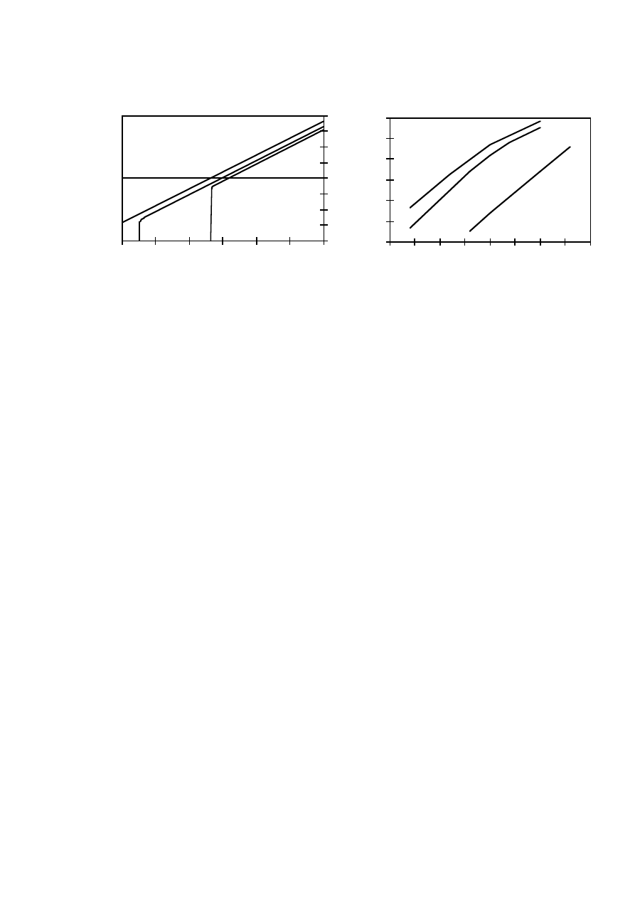
27
Field strength (kA/m)
-1.2
-0.9
-0.6
-0.3
0
0.3
0.6
0.9
1.2
-1500
-1250
-1000
-750
-500
-250
0
Flux density (T)
20 'C
100 'C
150 'C
Temperature ('C)
-1.2
-0.9
-0.6
-0.3
0
0.3
0.6
0
25
50
75
100
125
150
175
200
Minimum flux density (T)
A (new)
B
A (old)
Figure 2. Demagnetisation curves at different
temperatures for magnet B.
Figure 3. Temperature/flux density limits for
magnet material demagnetisation. Magnets A
and B.
One of the most critical situations for the magnet material demagnetisation is a short circuit at
the machine terminals. A sudden three-phase, and also in some cases a two-phase, short circuit at
the machine terminals at rated load is analysed in this study. The machine should be designed so
that the demagnetisation problem can be avoided, or a certain percentage of demagnetisation at a
possible maximum current and temperature is allowed.
The corrosion of the magnet material can be a problem, especially in offshore wind turbines.
The corrosion can be avoided by coating the magnets, for example with Nickel or Aluminium-
chromate coatings. The magnets of the experimental machines are protected from corrosion by
using dip impregnation.
The high energy magnets must be magnetised before they can be assembled on to the rotor. It is
not possible to get high enough flux density in the rotor core for magnetising the magnets because
of the saturated rotor iron. The mounting of the magnetised magnets on the rotor are usually
complicated and special tools must be used.
3.2
Background of the Optimisation
The machines are optimised using a genetic algorithm combined with the finite element method.
For optimising an electrical machine, several features need to be considered. The operational
characteristics of the machine should be sufficient and the cost of the machine low. The
optimisation problem is to find a design which fulfils all the requirements. However, there are
many possibilities for choosing an objective function. The objective function can, for instance, be
the cost, the pull-out torque, the efficiency or a combination of these.
The first optimisation problem considered is finding a design which is as cheap as possible. The
objective function is the cost of active materials (Cost). The cost of active parts of the machine is
based on the assumption that the cost of the materials and the manufacturing can roughly be

28
estimated as a cost per active weight of the different materials. The costs of the materials used in
the optimisation are given in Table 4. The cost of the copper includes the manufacturing cost of the
winding. The punching and the waste parts of the sheet are taken into account in the iron cost. The
magnets have been divided into sufficient pieces, phosphorated and magnetised. However, the
material and manufacturing costs change continually and, therefore, the cost ratio between the
materials is more important than the real cost of each material in the comparison of the machines.
Table 4. Costs of the materials.
Material
Cost [EUR/kg]
NdFeB magnets
Copper
Iron
100
6
3
The second optimisation problem considered is finding a design which has a high pull-out
torque. However, if the objective function is the pull-out torque, the optimisation leads to a very
expensive design. Therefore, the objective function is chosen to be the pull-out torque per the cost
of active materials (T
max
/Cost), which is reasonable in the comparison of different designs.
The third optimisation problem considered is finding a design which has high efficiency. The
objective function is the electromagnetic losses.
The summary of the main data of the optimisations is given in Table 5. Twenty-eight different
designs of the PM machines are optimised in this study. The optimisations have 5–8 free
parameters and some constant parameters. The other dimensions are calculated from the given
parameters.
In the structural optimisation especially, the unconstrained optimisation easily leads to designs
that could hardly be realised. The minimum pull-out torque, the minimum efficiency, the minimum
power factor and in some cases the maximum cogging torque are used as constraints in the
optimisation.
Some dimensions of the machines are chosen before the optimisation process. In this way, the
number of free variables can also be reduced. The maximum size of the machine usually depends
on the applications. The outer diameter of the machines is chosen to be constant in most of the
optimisations, because the diameter should not be too large in wind power plants. The
manufacturing process and the strength of the design should also be taken into account when
designing an electrical machine. The stator and rotor yoke heights have lower limits so that the
design is rigid enough. The yoke heights are chosen to be constant in most of the optimisations,
although electromagnetically the yoke height would not have to be so large.
The genetic algorithm combined with the finite element method was successfully used for
optimisations of low-speed PM machines for gearless wind turbines. The finite element method
gives detailed information of the electrical characteristics of the machines and various machine
designs can reliably be compared with each other. However, the genetic algorithm combined with
the finite element method used consumes plenty of computer time.

29
Table 5. Data on the optimisations of PM machines. F means free variable, C constant parameter,
b
s
stator slot width and * coupling between the diameter and the length (machine constant is equal).
Publication
5
5
6
7
9
9
9
10
Output power [kW]
Machine type
- Diamond winding
- Single-coil winding
Objective function
- Efficiency
- Cost
- Pull-out torque / Cost
Constraints
- Pull-out torque
- Efficiency
- Power factor
- Cogging torque
Different constructions
Free parameters
5.5
x
-
-
x
x
x
x
x
-
10
6/8
10
x
-
-
-
x
x
x
x
-
7
5/7
500
-
x
x
-
-
x
-
x
x
1
7
5.5
-
x
-
x
-
x
x
x
-
2
8
5.5
x
x
-
x
x
x
x
x
-
4
6
10
x
x
-
-
x
x
x
x
-
3
5
500
x
x
-
x
-
x
x
x
x
3
5
500
x
-
-
x
-
x
x
x
x
2
5
Parameter
- Machine constant
- Outer diameter
- Core length
- Air-gap length
- Stator slot width
- Stator slot height
- Stator slot opening width
- Stator slot opening height
- Magnet width
- Magnet height
- Pole shoe width
- Pole shoe height
- Stator yoke height
- Rotor yoke height
- Number of conductors in
a stator slot
-
C
F
C
F
F
C
C
F
F
F/-
F/-
C
C
F
-
C
C
C
F
F
C
C
F
F
F/-
F/-
C
C
F
C*
F*
F*
C
F
F
=b
s
F
F
C
-
-
F
F
C
-
C
F
F
F
F
F
C
F
F
-
-
C
C
F
-
C
F
C
F
F
C
C
F
F
-
-
C
C
F
-
C
C
C
F
F
C
C
F
F
-
-
C
C
F
-
C
C
C
F
F
C/b
s
C
F
F
-
-
C
C
F
-
C
C
C
F
F
C
C
F
F
-
-
C
C
F
3.3
Conventional PM Synchronous Machines [1–5]
3.3.1
Machine Topology
The cross-sectional geometry of the conventional PM synchronous machine is shown in Fig. 4
and the phase belts of the winding in Table 6. The main data of the machines analysed are shown in
Table 7. The machines have a three-phase, two-layer, round-wire diamond winding. Different stato
and rotor designs of the machine have been compared in this study. The machines have NdFeB
permanent magnets and they are mounted on the surface of the rotor yoke or below the pole shoes.
The rotor core is made of solid iron and also in some cases of electrical sheets. The machines
chosen for further analysis have fractional-slot windings and the number of stator slots per pole and
phase is q=1.5.
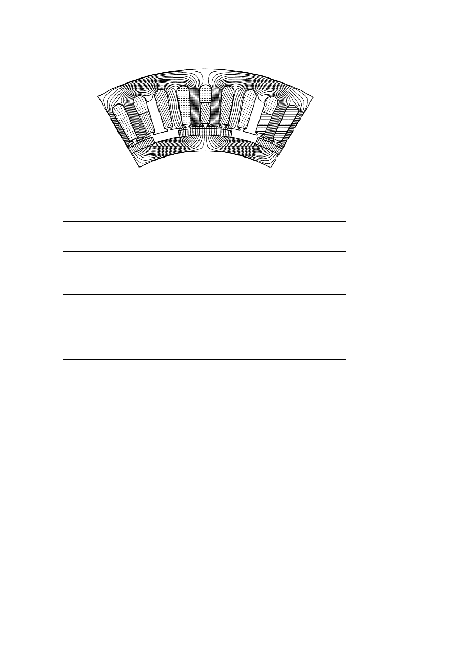
30
Figure 4. Cross-sectional geometry of the PM machine.
Table 6. Phase belts of the three-phase two-layer winding of the PM machine.
Slot number
1
2
3
4
5
6
7
8
9
Bottom layer
A
A
-C
B
B
-A
C
C
-B
Top layer
A
-C
-C
B
-A
-A
C
-B
-B
Table 7. Main data of the PM machines analysed.
5.5 kW
10 kW
500 kW
500 kW
Rated output [kW]
Rated frequency [Hz]
Rated speed [rpm]
Number of poles
Number of phases
Number of stator slots
Connection
5.5
17.5
175
12
3
54
Wye
10
17.5
175
12
3
54
Wye
500
26.7
40
80
3
360
Wye
500
50
40
152
3
684
Wye
3.3.2
Design of the Machines [1]
The main results of the design and the analysis of a 500 kW, 80 pole PM machine are presented
in this section. An example of a 152 pole machine is also presented. The results are presented in
more detail in publication [1]. The aim of the work is to find a suitable electromagnetic design for
the directly driven low-speed generator.
Several features should be taken into account when designing an electrical machine. The
magnet height affects, for instance, the air-gap flux density of the machine. According to the
analysis, the need for magnet material increases rapidly when the peak air-gap flux density exceeds
0.8 T. The magnet width also affects the voltage waveform, the air-gap torque and torque ripple of
the machine.
The torque ripple can cause problems of noise and vibration and the cogging torque especially
can make the starting of the machine difficult. The torque ripple depends, for instance, on the
magnet width, stator slot width and the number of stator slots per pole and phase, q. By using
different values of q, the analysis shows that one minimum point is almost at the same magnet
width, 2/3 times the pole pitch. By using a fractional slot winding the torque ripple is smaller than

31
with an integral slot winding. The torque ripple can also be decreased if the width of the slot
opening is as small as possible.
Usually, most of the losses in PM machines are concentrated in the stator winding but there can
also be high losses in the rotor. The eddy-current losses in rotor iron (solid steel) and magnets are
very high, 0.5–1.1% of the output power at rated load, when the number of slots per pole and phase,
q, is 1 or 1.25. With so few slots per pole and phase, the stator magneto motive force contains a lot
of harmonics. When q is more than 1.5, the rotor eddy-current losses are low, less than 0.1% of the
output power at rated load. The electromagnetic losses also depend on the magnet width. The
machine has high efficiency, when the width of the magnet is over 2/3 of the pole pitch. The
analysis also shows that the pull-out torque versus magnet weight is highest when the width of the
magnets is 65–80% of the pole pitch.
As a summary of the design, the electromagnetic properties of the PM machine are highly
dependent on the number of stator slots per pole and phase as well as the shape of the magnets, the
stator slots and the slot opening. Very much magnet material would have to be used in the machine
designed if the peak air-gap flux density should exceed 0.8 T. The pull-out torque versus magne
weight is highest when the width of the magnets is 65–80% of the pole pitch. The torque ripple can
be made low by using fractional slot winding, suitable magnet width and small slot opening width.
The good compromise of the magnet width is 2/3 times the pole pitch, if the torque ripple and
voltage waveform are also taken into account.
3.3.3
Machine with a Diode Rectifier Load [2–4]
The main results of the electromagnetic analysis of a 500 kW, 80 pole PM machine connected
to a frequency converter are presented in this section. The results are presented in more detail in
publications [2–4]. The aim of publication [2] is to compare the characteristics of the PM machine
with a diode rectifier and a resistive load. The characteristics of the machine with different magnet
width are analysed in a diode rectifier load in publication [3]. The losses of a the machine are
analysed in a diode rectifier load in publication [4].
A synchronous machine can be directly connected to a simple diode rectifier. The price of a
diode rectifier is low and control electronics are not needed. The electrical characteristics of the
machine with a diode rectifier load are calculated with a circuit simulator combined with two-
dimensional finite element modelling of electrical machines. The electric circuit of the simulation is
presented in Fig. 5. The frequency converter consists of a rectifier, an intermediate circuit and an
inverter unit. A rectifier with a current source type intermediate circuit (L) is used. The inverter
unit, which takes active power from the intermediate circuit, is replaced by a resistor (R
L
).
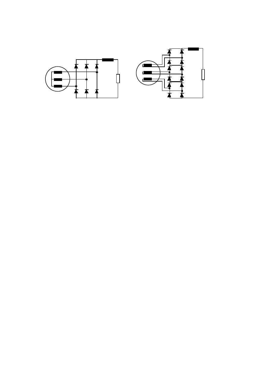
32
R
L1
PM Generator
L
1
R
L2
PM
Generator
L
2
Figure 5. A PM generator feeding a conventional and a special six-pulse diode rectifier.
First, the characteristics of the machine with a resistive and two different diode rectifier loads
are compared [2]. The first circuit is a conventional and the second one a special six-pulse diode
rectifier. The leading time of the diodes of one phase is longer in the special diode rectifier than in
the conventional one and, therefore, it may be possible to use the stator winding effectively. A
diode rectifier causes harmonics in the phase currents and is not able to deliver reactive power to
the machine. The maximum electrical output of the machine is lower in the diode rectifier load than
the output when connected directly to the sinusoidal grid. The terminal voltage of the machine
decreases when the load increases. Furthermore, the high load affects the voltage drop. The load
capacity of the machine in the rectifier load is less than 81% of the load capacity in the resistive
load, when the total electromagnetic losses of the machine are equal under different load
conditions. The stator resistive and rotor eddy-current losses are high with the rectifier loads. The
load capacity and the maximum output power of the machine with the special rectifier load are
lower than those of the conventional rectifier load and in the resistive load. The reason is that the
low order harmonic contents is higher and the power factor and the terminal voltage lower in the
special rectifier load than those in the other cases.
The characteristics of the machine with different magnet width are analysed in a diode rectifier
load in publication [3]. According to the calculation the maximum output power and the efficiency
of the machine can be improved by increasing the volume of the magnet material, and they can be
improved more as a function of the magnet weight by increasing the magnet height than by
increasing the magnet width. The pull-out torque per magnet weight is highest when the width of
the magnets is 65–80% of the pole pitch.
The losses of the machine are analysed in a diode rectifier load in publication [4]. The stator
losses are higher in the rectifier load than in the resistive one. The rotor core is made of conducting
material (solid steel) and most of the rotor losses are eddy current losses caused by high-frequency
flux variations. On the other hand, rotor core and permanent magnets have very low losses in
resistive load. Thus, the rotor losses are much higher in the rectifier load than in the resistive load.
A high efficiency is obtained when the width of the magnets is 65–80% of the pole pitch. If the
magnet width is less than 60% of the pole pitch, the machine has high efficiency only at low load.

33
As a summary of the analysis, the efficiency, the load capacity and the maximum output power
of the machine are lower in diode rectifier loads than that when connected directly to a sinusoidal
grid. The maximum output power and the efficiency of the machine can be improved by increasing
the volume of the magnet material and they improved more as a function of the magnet weight by
increasing the magnet height than the magnet width. The efficiency of the machine is high when the
magnet width is 65–80% of the pole pitch. If the magnet width is less than 60% of the pole pitch,
the machine has high efficiency only at low load.
3.3.4
Comparison of Different Rotor Designs [5]
Various rotor designs of a 5.5 kW and a 10 kW PM machine are optimised and compared in th
section. The results are presented in more detail in publication [5]. The aim of the comparison is to
find a suitable rotor design for the low-speed PM machine.
Five different rotor designs are investigated. The cross-sectional geometries of the machines are
shown in Fig. 6. The following abbreviations are used for the rotor designs:
SM
Curved surface-mounted magnets
RM-1
Rectangular surface-mounted magnets, one magnet per pole
RM-3
Rectangular surface-mounted magnets, three parallel magnets per pole
PS-1
Rectangular magnets equipped with pole shoes, constant air-gap length
PS-2
Rectangular magnets equipped with pole shoes, air-gap length varies
The first rotor (SM) has curved surface-mounted magnets. The air-gap length between the
magnets and the stator core is constant. The surface-mounted magnets should be mechanically
protected by a band surrounding the rotor and, therefore, the air-gap length should be large enough.
The shape of curved magnets depends on the rotor diameter. The manufacturing of curved magnets
is more complex than that of rectangular magnets. The cost of curved magnets is about 3–6%
higher than the cost of rectangular magnets depending of the shape of the magnets.
The second and third rotors (RM-1, RM-3) have rectangular magnets. One size of the magnets
can be used in different machines by varying the number of parallel magnets. If only one magnet
per pole (RM-1) is used, the air-gap length will be some millimetres larger in the middle of the
magnet (pole) than at the edge of the magnet when the rotor diameter is small. The rotor
construction of rectangular magnets is more complex than that of the curved magnets and the
assembly of many parallel rectangular magnets may be difficult.
The fourth and fifth rotors (PS-1, PS-2) have pole shoes. The air-gap length is constant in the
PS-1 machine. In the PS-2 machine, the air-gap length varies; at 60 electrical degrees the air-gap
length has twice the value of the pole centre. A binding is not needed to be used and the air-gap
length can be small. The pole shoes protect the magnets mechanically and magnetically from
demagnetisation. A disadvantage of the pole-shoe machines is the complex design.
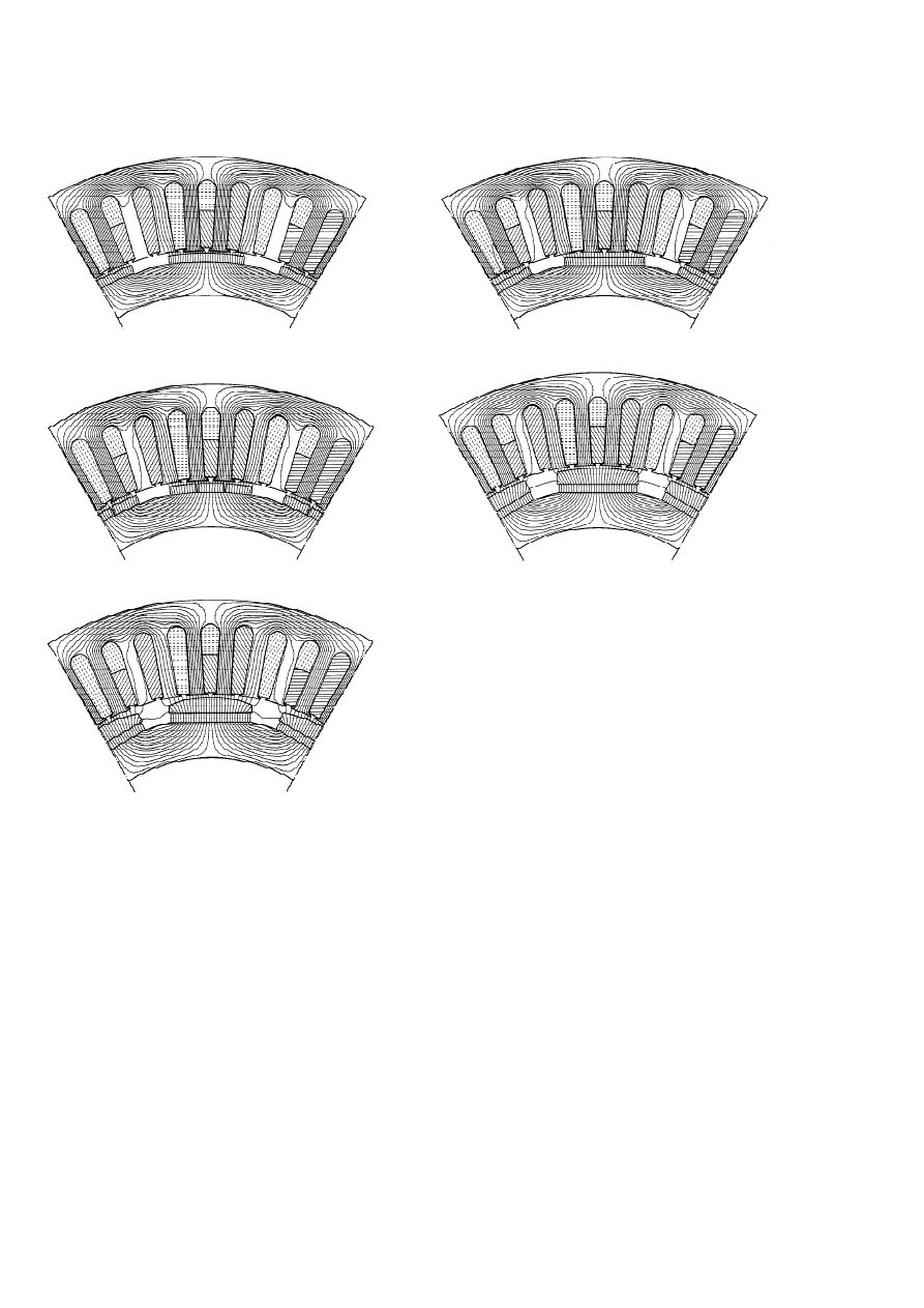
34
SM:
RM-1:
RM-3:
PS-1:
PS-2:
Figure 6. Cross-sectional geometries of the PM machines.
The machines compared are first optimised by using equal constraints and after that compared
with each other. The first optimisation problem considered is to find a design which is as cheap as
possible. The objective function is the cost of active materials (Cost). The second optimisation
problem considered is to find a design which has a high pull-out torque. The objective function is
the pull-out torque per the cost of active materials (T
max
/Cost). The main data of the optimisation
are shown in Table 5 in page 28. The optimisation of the surface-magnet machines includes six free
variables and the pole-shoe versions eight free variables, because of the more complex design.
The optimisation results are shown in Figs. 7 and 8. The best rotor design has curved surface-
mounted magnets (SM). The cost of active materials is the lowest and the pull-out torque per the
cost of active materials the highest in this design. The machine is also shortest, when the length of
the machine can vary in the optimisation. The second best rotor design has three parallel
rectangular surface-mounted magnets in each pole (RM-3). If the machine has only one rectangular
magnet per pole (RM-1), the pull-out torque per the cost of active materials is the lowest in the
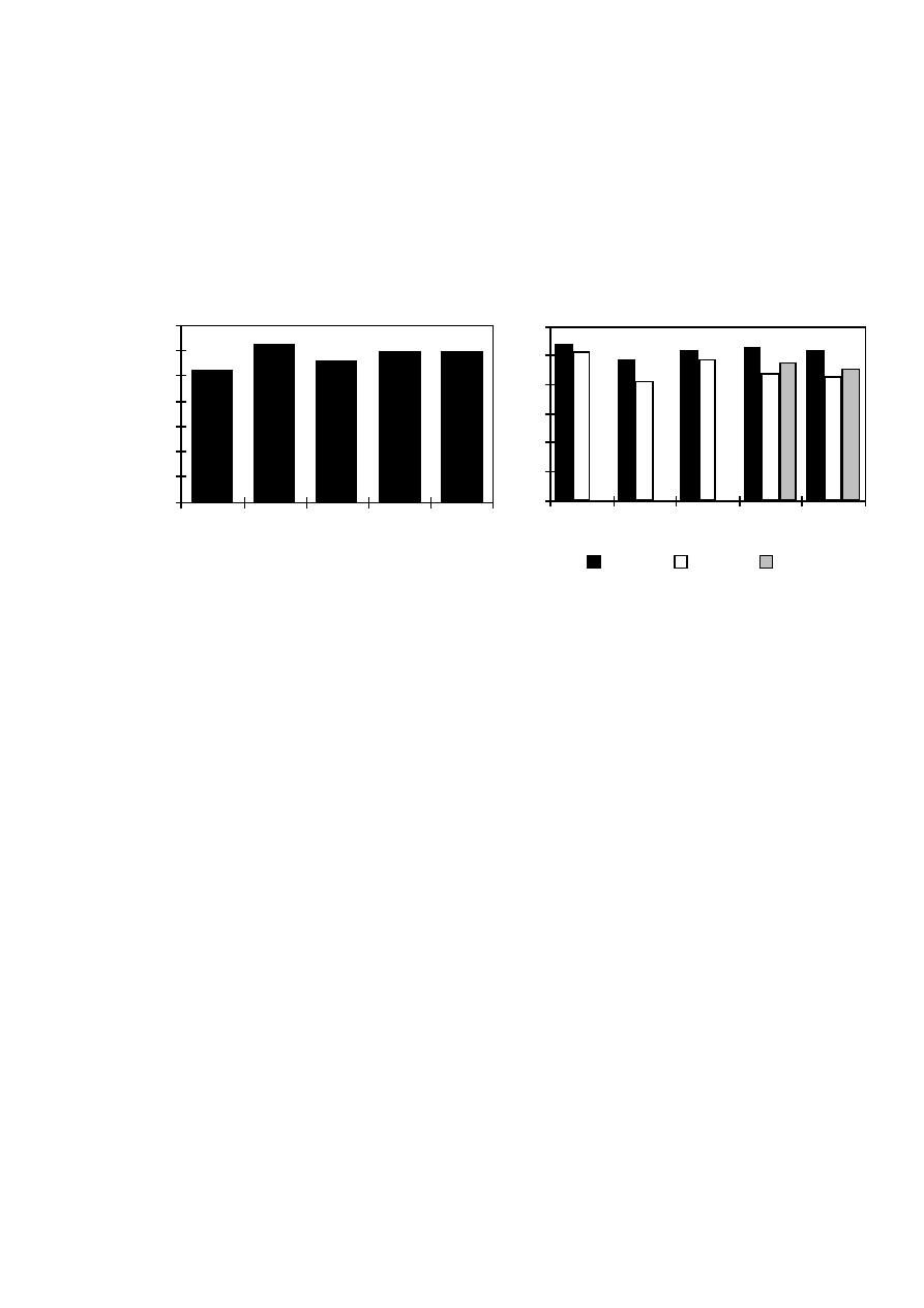
35
optimisation. In this design, the average air-gap length between the magnets and the stator surface
increases and this affects to the air-gap flux density negatively. The results of the pole-shoe
machine with a constant air gap between the stator and pole shoe (PS-1) and the machine with more
curved pole shoes (PS-2) are almost similar. The voltage waveform can be made sinusoidal by
using the curved pole shoe, but then the average air-gap length also increases.
0
100
200
300
400
500
600
700
SM
RM-1
RM-3
PS-1
PS-2
Cost (EUR)
0
0.3
0.6
0.9
1.2
1.5
1.8
SM
RM-1
RM-3
PS-1
PS-2
5.5 kW
10 kW S
10 kW L
Tmax / Cost (Nm/EUR)
Figure 7. Cost of active materials. 5.5 kW PM
machine.
Figure 8. Pull-out torque per the cost of
active materials. Solid (S) and laminated (L)
pole shoes.
The analyses of the torque ripple and the minimum flux density in permanent magnets are not
included in the optimisation, but the phenomena are studied separately. The torque ripple analysis
shows that there are three different torque ripple minima within the magnet width of 60–100% of
the pole pitch. The cogging torque can be reduced to less than 1% of the rated torque in all the
designs analysed by choosing a suitable magnet width. On the other hand, for the pole-shoe
machine with unconstant air gap (PS-2), the cogging torque at any pole shoe width is under 1% of
the rated torque. The torque ripple depends on the distance between two magnets in the three
rectangular-magnet machine (RM-3). Thus, the torque ripple contents of the machines are highly
dependent on the relative movement of the stator slots and the magnets and also the form of the air-
gap flux density, i.e. is it a sinusoidal or a rectangular form having a lot of low order harmonics.
The minimum flux density in permanent magnets is analysed during a sudden three-phase short
circuit. The analysis shows that the minimum flux density of the surface-magnet machine is lower
than that in the pole-shoe versions. The minimum flux density in the permanent magnets is the
highest, when the stator slot and tooth widths are narrow, i.e. the number of poles is large. The risk
of demagnetisation can be decreased by increasing the magnet height, i.e. by increasing the
magnetic flux density in the air gap. An advantage of the pole shoes is that the magnets can reliably
be protected against demagnetisation. In this case, the stator demagnetising flux does not penetrate
significantly into the magnets. However, the eddy-current losses in the solid pole-shoe rotor are
rather high, more than 1.5% of the output power at rated load. The risk of demagnetisation can be

36
reduced in a surface-magnet machine by using advanced magnet materials and sufficient magnet
thickness.
The investigation of various rotor designs shows that the rotor equipped with curved surface-
mounted magnets has various advantages. The cost of active materials is the lowest and the pull-out
torque per the cost of active materials the highest in this design. The second best rotor design has
three parallel rectangular surface-mounted magnets in each pole. The pull-out torque per the cost of
the active material of the rotor design of one rectangular magnet per pole is the lowest in the
optimisations. The magnets can reliably be protected mechanically and magnetically by using the
pole shoes. The risk of demagnetisation can be reduced in a surface-magnet machine by using
advanced magnet materials and sufficient magnet thickness. The cogging torque can be reduced to
less than 1% of the rated torque in all the designs compared by choosing a suitable magnet width.
3.3.5
Experimental Machine [5]
A 10 kW prototype PM machine was built and tested and it is presented in publication [5]. A
picture of the machine is shown in Fig. 9. The number of poles is 12 and the number of stator slots
per pole and phase 1.5. The outer diameter of the machine is 400 mm and the stator and rotor core
lengths are 200 mm. The machine has three parallel rectangular magnets in each pole (RM-3). The
magnets are divided into four parts in the axial direction and mechanically protected by a glass-
fibre band surrounding the rotor.
The laboratory set-up used for testing the PM machine and the equipments used in the
experiments are presented in Appendix. The prototype machine was first tested by rotating the
machine as a generator. The measured open-circuit voltage is 376 V and the calculated one 380 V.
The phase-to-phase voltages of the machine are almost sinusoidal. The measured harmonic voltage
factor (HVF) [IEC 34-1] in each phase is lower than 4.5% and in line-to-line voltage 0.6%. The
HVF is computed by using the following formula:
HVF
=
u
n
2
n
∑
,
(3)
where u
n
is the per unit value of the harmonic voltage and n is the order of harmonic. The measured
and the calculated cogging torque is 5 Nm, i.e. 1% of the rated torque. The calculated synchronous
reactance of the machine is 4.8
Ω
(x
d
=0.33) and the measured stator resistance 1.3
Ω
. The
calculated minimum flux density in permanent magnets during a sudden three-phase short circuit
is 0.03 T.
The prototype machine was tested as a motor, too. In this case the machine is fed by a PWM
frequency converter. The terminal voltage of the machine is 411 V and the frequency 18 Hz in the
load test. The torque-current charasteristics and the efficiency of the machine are shown in Figs. 10
and 11. The measured pull-out torque is 1330 Nm in converter supply and the calculated one
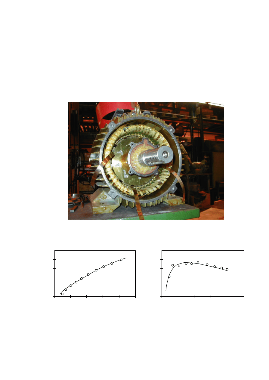
37
1400 Nm in sinusoidal supply. The measured total efficiency at rated load is 90.9%. The measured no-
load losses are 23 W. The calculated efficiency is 90.8% in sinusoidal supply without the cooling and the
bearing losses and 90.6% with them. The efficiency of the machine is also high at partial load. The
calculated torque ripple at rated load is 29 Nm, i.e. 5%.
The prototype machine has moderate torque ripple and high efficiency, furthermore, the voltage
waveform is almost sinusoidal. The computed results agree well with the measured ones. The machine type
can be used, for example, as a wind power generator or as a machine in other low-speed applications.
Figure 9. The prototype PM machine.
Current (A)
0
300
600
900
1200
1500
0
10
20
30
40
50
Torque (Nm)
- Calculated
o Measured
Shaft power (kW)
0.75
0.80
0.85
0.90
0.95
1.00
0
3
6
9
12
15
Efficiency
o Measured
- Calculated
Figure 10. Torque-current characteristics of the
prototype machine.
Figure 11. Total efficiency of the prototype
machine.
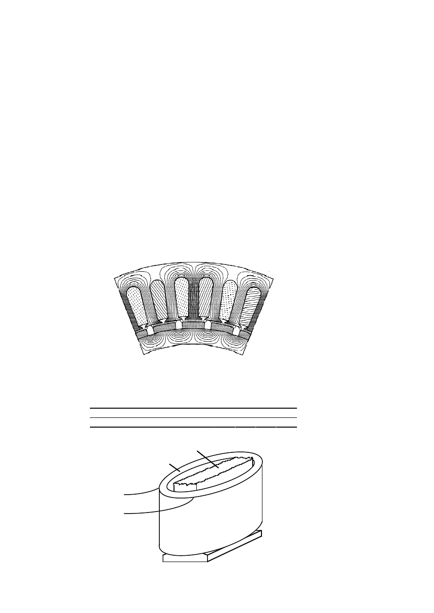
38
3.4
Single-Coil Winding PM Synchronous Machines [6–8]
3.4.1
Machine Topology
The single-coil winding PM machines have a special type of stator winding. The cross-sectional
geometry of the machine is shown in Fig. 12 and the phase belts of the winding in Table 8. The coil
design of the winding is shown in Fig. 13. The main data of the machines are shown in Table 9.
The machines have a three-phase winding consisting of coils which are placed in slots around every
second tooth. The stator winding can be assembled from the same types of coils used in a small
transformer. The stator slots can be open or semi-closed. The length of the overhang winding is as
short as possible. Furthermore, the coils of two phases are not close to each other in the winding
overhangs and the phase insulation is not needed. The coils of each phase can be connected in
parallel or in series. The stator core can be wound directly from the tape of the electricity sheets.
The number of stator slots per pole is small, only 1.5 (i.e. q = 0.5), and therefore, the pole pitch can
be very small. The design of the machine is very simple and it is easy to manufacture.
Figure 12. Cross-sectional geometry of the single-coil winding PM machine.
Table 8. Phase belts of the three-phase winding of the PM machine.
Slot number
1
2
3
4
5
6
Phase
A
-A
C
-C
B
-B
Tooth
Coil
Figure 13. Winding design of the single-coil winding PM machine.

39
Table 9. Main parameters of the single-coil winding PM machines analysed.
5.5 kW
10 kW
500 kW
Rated output power [kW]
Rated frequency [Hz]
Rated speed [rpm]
Number of poles
Number of phases
Number of stator slots
Connection
5.5
46.7
175
32
3
48
Wye
10
46.7
175
32
3
48
Wye
500
50
40
152
3
228
Wye
3.4.2
Design of the Machines [6–7]
The main results of the design and optimisation of a single-coil winding 500 kW and a 5.5 kW
PM machine are presented in this section. The results are presented in more detail in publications
[6–7]. The aim of these publications is to find a suitable electromagnetic design for the directly
driven low-speed generator. The electromagnetic design and the optimisation of the 500 kW
machine are presented in publication [6] and the 5.5 kW machine with two different magnet design
in publication [7].
The torque ripple of the machine depends, for instance, on the stator slot and slot opening width
and the magnet width. The analysis of the machine shows that there is one torque ripple minimum
between the magnet width of 60–100% of the pole pitch. The minimum is obtained at the magnet
width of 74–80% of the pole pitch,
when the slot width is 30–70% of the slot pitch. The torque
ripple is minimum when the slot opening is as small as possible. Even with open slots the cogging
torque is under 7% of the rated torque. The torque ripple can also be reduced by skewing the stator
slots or permanent magnets.
The minimum flux density in permanent magnets is analysed during a sudden three-phase short
circuit at machine terminals. The minimum flux density in the permanent magnet during the short
circuit is positive, in the analysed case over 0.2 T. Although the machine has surface mounted
permanent magnets or open stator slots, the demagnetisation can be avoided during a three-phase
short circuit.
An optimisation of a 500 kW machine is presented in publication [6]. The objective function
the efficiency at rated load. The main data of the optimisation are shown in Table 5, on page 2
The optimisation has seven free parameters. The designs have the same machine constant, i.e. the
rotor volume is constant. If the magnet height were a free parameter, it would lead to a very
expensive design.
The rotor yoke height decreased from the initial value of 20 mm to 8.5 mm during th
optimisation so that the iron of the yoke saturated. Therefore, the eddy-current losses in permanent
magnets reduced by 30% from the initial values. The total electromagnetic losses of the machine
optimised decreased by 10% from the initial values. Most of the changes in the machine

40
dimensions are rather small in the optimised machine compared to the initial machine. This is
caused by the constraints of the pull-out torque and the torque ripple.
An electromagnetic design and optimisation of a 5.5 kW machine with two magnet designs is
presented in publication [7]. The first variant has one magnet per pole and the second variant two
magnets per pole. The objective function is the cost of active materials. The main data of the
optimisation are shown in Table 5, on page 28. The optimisation has 8 free parameters. The
dimension of the machine is larger if we divide the magnet in the axial direction and leave a rather
large span between two magnets. There are local minima in the air-gap flux density above the
magnet span. The length of the machine is 11% longer, air gap length 8% and magnet height 45%
higher in the two-magnet machine than in the one-magnet machine. Furthermore, the total weight is
13% higher and active materials 43% more expensive. The span between the two magnets affects
the machine characteristics considerably and it increases the volume of the machine and the cost of
active materials.
As a summary of the design, the torque ripple minimum of the single-coil winding machine is
obtained at a magnet width of about 75% of the pole pitch when the slot width is half of the slot
pitch. The torque ripple can also be reduced by decreasing the slot opening width and it is rather
low even with open slots. Although the machine has surface-mounted permanent magnets or open
stator slots, the demagnetisation can be avoided during a three-phase short circuit. If two parallel
magnets per pole instead of one magnet are used, the span between the two magnets affects the
machine characteristics considerably. The optimisation shows that the volume of the machine and
the cost of active materials increase in this case.
3.4.3
Experimental Machine [8]
A design and an analysis of a prototype machine are presented in publication [8]. A 7 kW
prototype machine was built and tested. A picture of the machine is shown in Fig. 14. The machine
was designed for sinusoidal supply. The line voltage of the machine is 400 V, the frequency 50 Hz
and the synchronous rotation speed 150 rpm. The stator is assembled from overlapped U-sheets
used in small transformer cores. The machine has a three-phase winding (30 coils) which creates 20
pole pairs. The stator has an outer diameter of 600 mm and the length of the core is 66 mm. The
rotor has 40 surface-mounted NdFeB permanent magnets, and they create a flux density of 0.9 T in
the air gap. The rotor is divided in the axial direction into three slices, which have been rotated with
respect to each other. As a result of this splitting, the magnets have been skewed with respect to the
stator slots.
The laboratory set-up used for testing the PM machine and the equipments used in the
experiments are presented in Appendix. The measured open-circuit voltage is 391 V and the
calculated one 396 V. The voltage waveform of the machine is almost sinusoidal. The measured
harmonic voltage factor (HVF) in each phase is lower than 0.8% and in line to line voltage 0.3%.
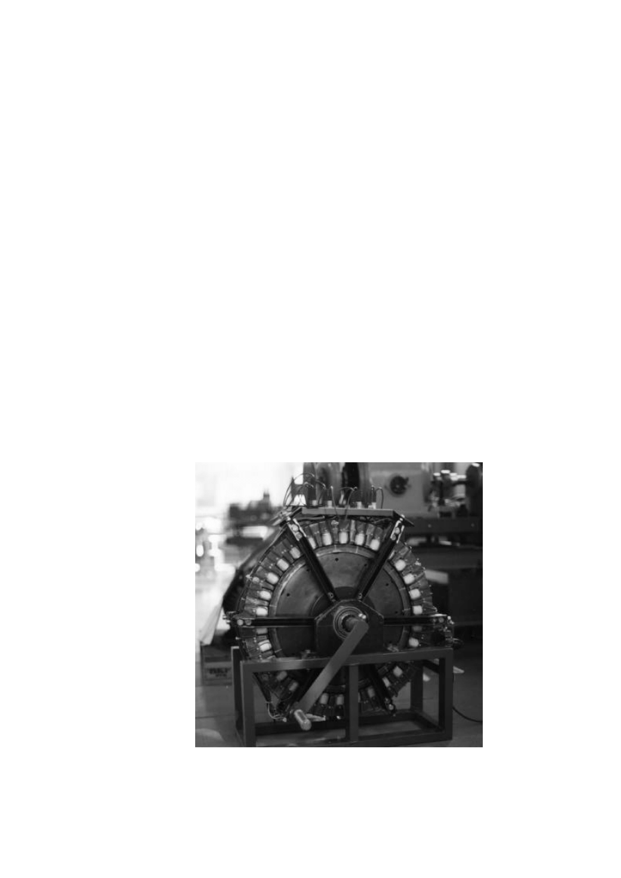
41
The third harmonic has the highest value, i.e. 1.2%. The reason for the low harmonic content is the three-
slice PM rotor, which at the same time damps the cogging torque and gives an almost sinusoidal flux
linkage distribution. The measured maximum value of cogging torque do not exceed 6 Nm, i.e. 1% of the
rated torque. The torque ripples are calculated without skewing and the cogging torque is 17 Nm, i.e. 4%
of the rated torque.
The loading properties of the machine are measured and calculated in generator use. The terminal
voltage is 400 V and the frequency 50 Hz. The synchronous reactance of the machine is 9.8
Ω
(x
d
=0.42)
and the stator resistance 1.7
Ω
. The torque-current charasteristics and the efficiency of the machine are
shown in Figs. 15 and 16. The pull-out torque of the machine is 1380 Nm. The measured efficiency at
rated load is 91.3% and the calculated one 90.9%. The efficiency of the machine is also high at partial
load. The measured no-load losses of the machine are 66 W. The torque ripples are calculated without
skewing and the torque ripple at rated load is 23 Nm, i.e. 5%.
In spite of the simple construction of the prototype machine, moderate torque ripple and high efficiency
are achieved and the voltage waveform is almost sinusoidal. The dimensions of the machine built are not
exactly the same as those of the designed one for constructional reasons. The stator is assembled from
many small ordinary transformer laminations and, therefore, the air gap length is not constant. Furthermore,
the rotor is skewed. However, the computed results agree rather well with the measured ones. The
machine can be used, for example, as a wind power generator or as a braking machine for a training and
rehabilitation device as described in Ref. [Tellinen et al. 1996].
Figure 14. The prototype PM machine.
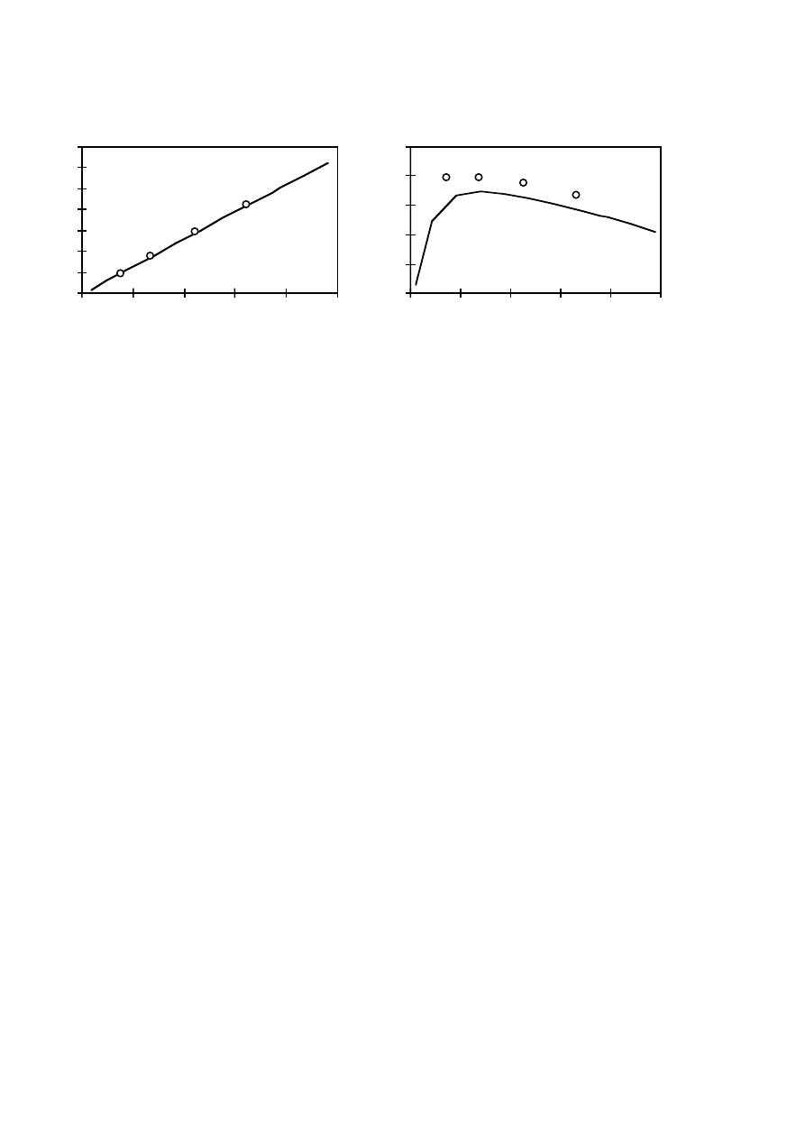
42
Current (A)
0
100
200
300
400
500
600
700
0
3
6
9
12
15
Torque (Nm)
o Measured
- Calculated
Shaft power (W)
0.75
0.80
0.85
0.90
0.95
1.00
0
2000
4000
6000
8000
10000
Efficiency
o Measured
- Calculated
Figure 15. Torque-current characteristics of the
prototype machine.
Figure 16. Efficiency of the prototype
machine.
3.5
Comparison of the PM Machines [9–10]
The main results of the optimisation and the comparison of two types of PM machines with
different kinds of stator windings are presented in this section. The results are presented in more
detail in publications [9–10]. The aim of the optimisation is to find a design with a high pull-out
torque and with a low active material cost. The optimisation and the comparison of the two types of
5.5 kW, 10 kW and 500 kW machines are presented in publication [9]. The optimisation of a
500 kW conventional machine with two different pole numbers is presented in publication [10].
First, two types of the 5.5 kW, 10 kW and 500 kW machines are optimised and compared. The
optimisation results are shown in Figs. 17 and 18. The characteristics and main data of the
machines are shown in Table 10. The objective functions are the cost of active materials and the
pull-out torque per the cost of active materials. The main data of the optimisation are shown in
Table 5, on page 28. The optimisation has 5–6 free parameters. The optimisation of the machines
shows that the pull-out torque per the cost of active materials is higher and the cost of active
materials smaller in the conventional machines (SM) than in the single-coil winding machines
(UC). The materials and the volumes of the conventional machines can be used more effectively
than those of the single-coil winding machines. Although the specifications of the optimisation of
the 5.5 kW, 10 kW and 500 kW machines are different, the optimisation results are similar.
Publication [10] presents the optimisation of a 500 kW conventional machine with two different
pole numbers. The objective function of the optimisation is the cost of active materials. The first
machine has 80 poles, i.e. the frequency is 26.7 Hz, and the second one 152 poles, i.e. 50 Hz. The
main data of the optimisation are shown in Table 5, on page 28. The optimisation has five free
parameters. The outer volume of the machines is constant in the optimisation. The outer diameter is
chosen to be 3 metres in the 80 pole machine and 3.5 metres in the 152 pole machine and, therefore,
the slot pitch is 38% smaller in the 152 pole than in the 80 pole machine. The optimisation results
are an example of the multipole design. The 152 pole machine has the lowest cost of active
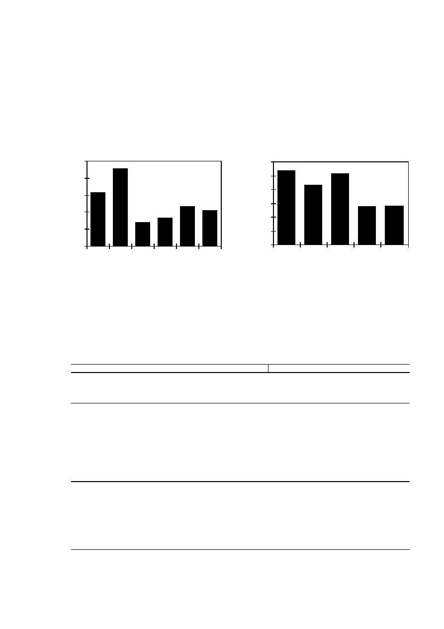
43
materials, and it is 16% smaller than in the 80 pole machine. The torque ripple and eddy current
losses in the rotor are small in both the machines. The minimum flux density in permanent magnets
of the 152 poles machine is higher during a three-phase short circuit and at a maximum load than
that in the 80 pole machine. Both conventional 500 kW machines are cheaper than the single-coi
winding machines.
0
30
60
90
120
150
SM
5.5
UC
5.5
SM
500
P80
SM
500
P152
UC
500
OS
UC
500
Cost / Output (EUR/kW)
0
0.3
0.6
0.9
1.2
1.5
1.8
SM
5.5
UC
5.5
SM
10
UC
10S
UC
10L
Tmax / Cost (Nm/EUR)
Figure 17. Cost of active materials. 80 pole
(P80) and 152 pole (P152) machine. Open
stator slots (OS).
Figure 18. Pull-out torque per the cost of
active materials. Solid (S) and laminated
(L) rotor core.
Table 10. Characteristics and main data of the PM machines optimised. Objective functions,
T
max
/Cost and Cost, in boldface. Open stator slots (OS).
Objective function
Tmax/Cost
Cost
Machine type
Rotor (solid / laminated)
Output power [kW]
Poles
SM
S
5.5
12
UC
L
5.5
32
SM
S
10
12
UC
S
10
32
UC
L
10
32
SM
S
5.5
12
UC
L
5.5
32
SM
S
500
80
SM
S
500
152
UC OS
L
500
152
UC
L
500
152
Efficiency [%]
Losses [kW]
-Resistive losses, stator
-Iron losses
-Eddy-current losses, rt.
Power factor
Tmax/Tn
Tmax/Cost [Nm/EUR]
Bmin [T] 3-p. short circuit
Bmin [T] 2-p. short circuit
90.0
0.514
0.093
0.003
0.82
3.4
1.61
-0.4
-0.1
90.1
0.301
0.190
0.111
0.80
3.7
1.30
+0.1
0.0
91.0
0.846
0.138
0.005
0.86
3.3
1.54
-0.3
-0.4
91.0
0.583
0.274
0.132
0.87
2.1
0.83
+0.1
0.0
91.0
0.632
0.274
0.081
0.81
2.1
0.85
+0.1
0.0
90.2
0.522
0.075
0.003
0.90
2.5
1.44
-0.4
-0.5
90.0
0.291
0.159
0.158
0.91
2.5
1.01
+0.1
-0.1
96.0
15.8
4.4
0.7
0.99
2.0
9.9
-0.3
-0.3
96.0
14.1
6.4
0.2
0.98
2.0
11.9
-0.1
0.0
91.0
16.0
6.6
26.9
0.97
1.8
6.8
0.0
-0.1
91.2
17.4
7.4
23.3
0.94
1.6
6.7
0.0
0.0
Outer diameter [mm]
Air-gap diameter [mm]
Core length [mm]
Weight [kg]
- Iron
- Copper
-Magnets (NdFeB)
-Total weight (active mat.)
Cost [EUR] (active mat.)
400
291
128
48
24
3.5
75
628
400
295
179
64
23
5.4
92
862
400
295
200
71
32
7.5
111
1152
400
273
200
75
32
9.9
117
1388
400
272
200
74
33
9.4
116
1347
400
290
117
42
26
2.5
70
520
400
292
206
71
29
3.8
104
755
3000
2819
424
2479
838
128
3445
25248
3500
3317
312
2119
712
106
2937
21196
3000
2818
424
2481
708
232
3421
34886
3000
2821
424
2689
521
206
3416
31810

44
The single-coil winding machines have higher harmonics and, therefore, higher eddy-current
losses in the rotor than the conventional machines. On the other hand, the design of the single-coil
winding machine is very simple and the machine is easy to manufacture. The number of stator slots
per pole and phase is small and, therefore, the pole pitch of the machine can be small. The width of
the stator slots and teeth has a lower constructive limit. For these reasons, the diameter of the
single-coil winding machine can be smaller than that of the conventional machine with equal output
frequency. The length of the overhang winding is as short as possible in the single-coil winding
machine. Furthermore, there is no overlap in the overhang winding, i.e. the conductors of different
coils are not close to each other. Therefore, the machine has a more reliable insulation system than
the conventional machine. The demagnetisation of permanent magnets is easier to avoid in the
single-coil winding machines than in the conventional designs analysed. The cogging torque can be
reduced to less than 2% of the rated torque by choosing a suitable magnet width and stator slot
opening width in both the designs.
The low-speed PM machines analysed have their advantages and disadvantages. Both types of
the PM machines would be available solutions for a directly driven wind generator. The active
material cost of the diamond winding PM machine is lower, but the design is more complex than
that in the single-coil winding PM machine.

45
4
DISCUSSION
The aim of this research is to find an optimal design for a low-speed generator for gearless wind
turbines. The hypothesis in this work is that the typical generator-gear solution in the wind power
plant can be replaced by a low-speed PM synchronous generator.
4.1
Wind Generators
The rotor of a present day typical wind turbine rotates at a speed of 20–200 rpm. The generato
is coupled to the turbine via a gear so that it can rotate at a speed of 1000 or 1500 rpm. Usually, the
generator is a four- or six-pole induction machine and it is connected directly to the grid.
The generator rotates at the same speed as the rotor of the turbine in a gearless wind turbine.
Many types of low-speed generators have been designed, for instance, special machines like radial-,
axial- and transverse-flux synchronous machines, reluctance machines and a linear induction
machine. The first commercial directly driven generator in the power range of some hundred
kilowatts was a synchronous machine excited by a traditional field winding. Nowadays, the greatest
interest is in PM generators for gearless wind power plants. The PM machines can operate with
good and reliable performance over a wide range of speeds. The pole pitch of the PM machine can
also be made small. Furthermore, the characteristics of permanent-magnet materials are improving
and their prices are decreasing. According to the earlier research, a multipole radial-flux PM
synchronous machine is a good alternative for the design of a large-scale directly driven wind-
turbine generator. Therefore, this type of machine was chosen for further investigation.
4.2
Optimisation Method
The electromagnetic optimisation of the machines was done using a genetic algorithm combined
with the finite element method. The genetic algorithm belongs to the group of probabilistic
searching methods, which have high probability of locating the global optimum in the
multidimensional searching space discarding all existing local optima [Palko 1996a]. The
calculation of the operating characteristics of the machines is based on a finite element analysis of
the magnetic field. To be able to evaluate the losses caused by higher harmonics, the rotation of the
rotor is taken into account and, therefore, a time-stepping method is used in the analysis. In order to
save optimisation time, the FEM analysis was made using first-order finite elements. The initial
values are obtained from a magnetostatic solution. The period of line frequency is divided into at
least 200 time steps and a total number of 250 time steps is used in the calculation of the operating
characteristics at rated load. The calculation of the pull-out torque is based on the assumption of
sinusoidal time variation of the stator voltages and currents. The open-circuit voltage and the
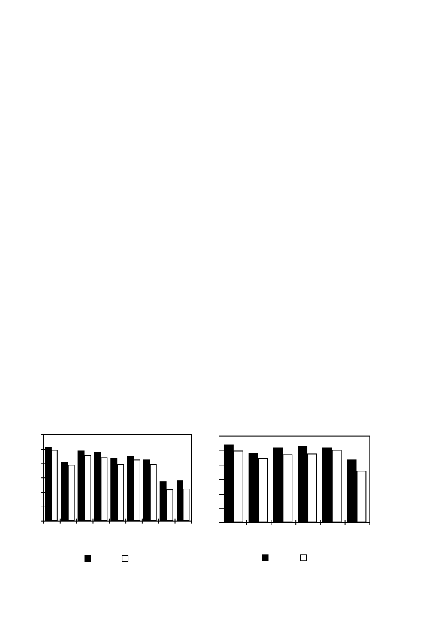
46
cogging torque are calculated dividing the period of line frequency into 300 time steps and using a
total number of 600 time steps in order to obtain more accurate results of the local field variations.
A typical first-order finite element mesh constructed for two pole pitches of the PM machine
contains 700–900 nodes.
The other FEM analysis of this work was made using second-order finite elements. The period
of line frequency is in most of the cases divided into 300 time steps and a total number of 600 time
steps is used in the calculation. A typical finite element mesh constructed for the two pole pitches
of the PM machine contains 2700–3500 nodes.
The optimisation results of the pull-out torque have been checked by using second-order finite
elements and time-stepping FEM. The period of line frequency is divided into 300 time steps. The
comparison of the pull-out torque per the cost of active material of the machines optimised using
first-order and second-order finite elements is shown in Figs. 19 and 20. The pull-out torque of the
conventional machines is on average 7% lower using second-order finite elements than using first-
order finite elements. The results of the conventional 10 kW machines differs by 4.5–7% and the
results of the 5.5 kW machines by 7–9%, except for the solid pole-shoe designs. The difference of
the results of the solid pole-shoe machines with constant air-gap, PS-1, is 9–10% and the machines
with curved pole-shoes, PS-2, 3–7%. The pull-out torque of the single-coil winding machines
differs on average by 20%, but on the other hand, the torque is also lowest in the optimisation. The
pull-out torque of all the machines optimised is lower using second-order finite elements and time-
stepping FEM than in the comparisons. The field quantities of the real machine do not vary
sinusoidally with time because of the saturation of the iron and the rotation of the rotor.
Furthermore, the first-order mesh is rougher than the second-order mesh. However, the order of the
machines in the comparisons is the same, except for the machines with solid pole shoes. The
difference of the results of the machines from each other is more important than the absolutely right
values in the comparisons. Therefore, the results are available for comparisons of the machines with
each other.
0.0
0.3
0.6
0.9
1.2
1.5
1.8
SM
RM-1
RM-3
PS-1 L
PS-1 S
PS-2 L
PS-2 S
UC L
UC S
1-order
2-order
Tmax / Cost (Nm/EUR)
0 . 0
0 . 3
0 . 6
0 . 9
1 . 2
1 . 5
1 . 8
SM
RM-1
RM-3
PS-1
PS-2
UC
1-order
2-order
Tmax / Cost (Nm/EUR)
Figure 19. Pull-out torque per the cost of
active materials of the 10 kW machines
optimised.
Figure 20. Pull-out torque per the cost of
active materials of the 5.5 kW machines
optimised. Solid pole shoes.
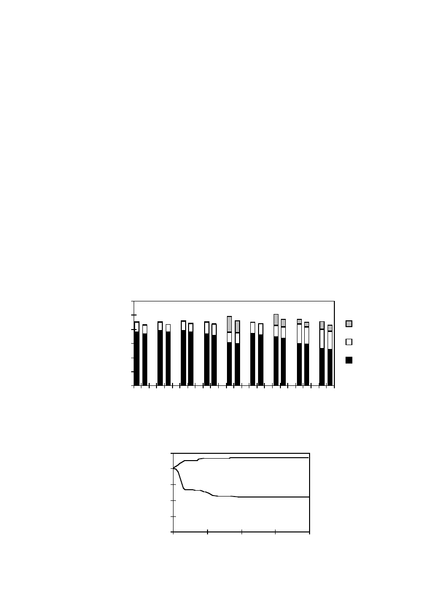
47
The stator resistive losses, the stator and rotor iron losses and the rotor eddy-current losses of
the 10 kW machines using first-order and second-order finite elements are shown in Fig. 21. The
period of line frequency is divided into 300 time steps in the first-order FEM and into 300 time
steps in the second-order FEM. The electrical power of the machines is 10 kW in the comparison
The losses are lower in all the cases using second-order finite elements than using first-order finite
elements. The difference of the efficiency is 0.3-0.4% without rotor eddy-current losses and 0.5-
0.8% with rotor eddy-current losses. The largest difference is in the eddy-current losses of the solid
pole shoes. The reason for the difference is that the first-order mesh is rougher than the second-
order mesh, and this affects the losses, especially in the air-gap region. Furthermore, the line
frequency of the first-order calculation is divided into fewer time steps than that in the second-order
calculation, which affects, for example, the voltage waveform.
The evaluation of the best design of the optimisation is shown in Fig. 22. The optimisations of
this study were made using a population size of 50 and the total number of generations was at least
60. The duration of one optimisation of 60 generations was 5–10 days using one processor of an
IBM AIX SP2 computer. After the first 40 generations, the results improve very little, less than
0.5%, and after the 60 generations less than 0.2%. Thus, the number of the generations in the
calculations was sufficient and they could even be smaller than used.
0
200
400
600
800
1000
1200
SM
RM-1
RM-3
PS-1 L
PS-1 S
PS-2 L
PS-2 S
UC L
UC S
Peddy
Pfe
Pcu
Losses (W)
Figure 21. The stator resistive losses, the iron losses and the rotor eddy-current losses of the
machines using first-order (left side) and second-order finite elements (right side).
Generations
0
25
50
75
100
125
0
20
40
60
80
Objective function (%)
Tmax / COST
COST
Figure 22. Time evolution of the best design. The objective functions are the pull-out torque and
the cost of the material.

48
The genetic algorithm combined with the finite element method was successfully used for
optimisations of low-speed PM machines for gearless wind turbines. The finite element method
gives detailed information of the electrical characteristics of the machines, and various machine
designs can reliably be compared with each other. However, the genetic algorithm combined with
the finite element method used consumes plenty of computer time.
4.3
Electromagnetic Characteristics of the Machines
Two types of multipole, radial-flux PM synchronous machines are designed and optimised. The
first machine has a conventional three-phase diamond winding. The second one has an
unconventional, three-phase single-coil winding. High-energy NdFeB magnets are chosen to be
used. These magnets give a sufficient air-gap flux density with a low volume of the magnet
material. The rated powers of the machines optimised are 500 kW, 10 kW and 5.5 kW.
The electromagnetic properties of the conventional PM machine are highly dependent on the
design, i.e. the number of stator slots per pole and phase as well as the shape of the magnets, the
stator slots and the slot openings. Very much magnet material would have to be used in the
machine designed if the peak air-gap flux density should exceed 0.8 T. The pull-out torque versus
magnet weight is highest when the width of the magnets is 65–80% of the pole pitch. Furthermore,
the efficiency of the machine is also high in this case. If the magnet width is large, the leakage flux
between the magnets becomes high. The voltage waveform is almost sinusoidal, when the magnet
width is two thirds of the pole pitch. The eddy-current losses in rotor iron (solid steel) and magnets
are very high, when the number of slots per pole and phase, q, is 1 or 1.25. With so few slots per
pole and phase, the stator magneto motive force contains a lot of harmonics. When q is more than
1.5, the rotor eddy-current losses are low. A low-speed machine has many poles and the diameter of
the wind-turbine generator should not be too large, i.e. the number of the stator slots should be
small. Therefore, the machine with q=1.5 is chosen for further analysis.
The torque ripple can cause problems of noise and vibration and the cogging torque especially
can make the machine difficult to start. When the rotor rotates and the flux from the magnets jumps
sharply from one stator tooth to another, the force caused by the magnetic field changes direction
rapidly. The result is a torque ripple around the average torque. The torque ripple is also partly
caused by the higher harmonics in the supply voltage. The stator winding is not sinusoidally
distributed along the air gap surface but embedded in the stator slots. This induces higher
harmonics in the flux distribution, which affects the torque.
The conventional machines have three different torque ripple minima within the magnet width
of 60–100% of the pole pitch. The torque ripple can be made low by using fractional slot winding,
suitable magnet width and small slot opening width. A good compromise for the magnet width is
two thirds of the pole pitch, if the torque ripple and voltage waveform are also taken into account.
The analysis of the unconventional single-coil winding machine shows that the torque ripple

49
minimum is obtained at a magnet width of about 75% of the pole pitch when the slot width is half
of the slot pitch. The torque ripple can also be reduced by decreasing the slot opening width and it
is rather low even with open slots. The cogging torque can be reduced to less than 2% of the rated
torque by choosing a suitable magnet width and the stator slot opening width in both the designs
analysed. The torque ripple can also be reduced by skewing the stator slots or magnets. However,
the skewed design is more complex than the unskewed one.
The efficiency, the load capacity and the maximum output power of the PM machine are lower
in diode rectifier loads than when connected directly to a sinusoidal grid. A diode rectifier causes
harmonics and is not able to deliver reactive power to the machine. The power factor and the
terminal voltage of the machine are lower and the stator resistive and the rotor eddy-current losses
higher in diode rectifier loads than when connected directly to a sinusoidal grid.
Various rotor designs of the conventional PM machine were investigated: curved and
rectangular surface-mounted magnets as well as rectangular magnets equipped with pole shoes. The
investigation shows that the rotor equipped with curved surface-mounted magnets has several
advantages. The cost of active materials is the lowest and the pull-out torque per the cost of active
materials the highest in this design. The rotor design is also simple. The second best rotor design
has three parallel rectangular surface-mounted magnets in each pole. If the machine has only one
rectangular magnet per pole, the pull-out torque per the cost of the active material is the lowest in
the optimisations. The air-gap length is larger in the middle than at the edge of the magnet, and this
affects the air-gap flux density. The main advantage of the pole-shoe machines is that the magnets
can be reliably protected mechanically and magnetically.
According to the optimisation of the machines with different stator winding, the pull-out torque
per cost of active material of the conventional PM machine is higher and the cost of active material
smaller than those of the single-coil winding machine, providing the other main electromagnetic
characteristics are equal. The single-coil winding machines have higher eddy-current losses in the
rotor than the conventional machines. On the other hand, the design of the single-coil winding
machine is very simple and the machine is easy to manufacture. The machine can be divided into
many identical sectors, which can be mounted in their places during the installation of the whole
wind turbine. The sectors can also be changed separately which makes the maintenance easy. The
length of the overhang winding is short and the number of stator slots per pole and phase is small,
and therefore, the diameter of the machine can be smaller than that of the conventional machine
with equal output frequency. The single-coil winding machine has a reliable insulation system
because there is no overlap in the overhang winding.
4.4
Demagnetisation of the Magnets
Demagnetisation can be a problem in a PM machine. The properties of the magnets depend
highly on the temperature of the magnets. The machine should be designed so that demagnetisation
can be avoided, or a certain percentage of demagnetisation at a possible maximum current and

50
temperature is allowed. One of the most critical situations is a short circuit at the machine
terminals. A sudden three-phase and a two-phase short circuit at the machine terminals at rated load
are analysed in this study. The minimum radial flux density in the permanent magnets is calculated
during the transient phenomenon.
The lowest minimum flux density of the magnets in the 5.5 kW machines optimised is minus
0.45 T, and the magnets can be protected against demagnetisation at a magnet temperature of 60 ˚C.
The 10 kW machines have better magnets and the maximum allowed temperature of the magnets is
more than 130 ˚C at the minimum flux density of minus 0.4 T. If the temperature is higher, the
magnets can be partially demagnetised. On the other hand, the efficiency of the machines is high
and the cooling surface of the multipole design is large.
The risk of demagnetisation can be decreased by using solid pole shoes and by using advanced
magnet materials and sufficient magnet thickness. Furthermore, the eddy-current losses, i.e. the
heating of the magnets, can be decreased by dividing the magnets into smaller parts. The
demagnetisation of permanent magnets is easier to avoid in the single-coil winding machines than
in the conventional machines analysed because of the stator tooth saturation. The demagnetisation
is not a problem in the conventional surface-magnet machines either.
4.5
Gearless and Geared Solutions
The electromechanical system of a conventional wind power plant consists of three main parts:
turbine, gearbox and generator. The generator is usually an induction machine and it is connected
directly to the grid. The speed of the generator is 1000 or 1500 rpm and this means that a gear is
needed between the turbine and the generator. However, the gearbox adds to the weight, generates
noise, demands regular maintenance and increases losses. Furthermore, there can also be problems
with materials, lubrication and bearing seals in cold climates.
The wind power plant can be simplified by eliminating the gear and by using a low-speed
generator the rotor of which rotates at the same speed as the rotor of the turbine. The number of
moving components and the noise caused mainly by high rotational speed of the gear can be
reduced. The advantages are also high overall efficiency and reliability, and diminished need for
maintenance. The cross-sectional geometry of the low-speed radial-flux PM synchronous generator
designed is shown in Fig. 23. The stator frame is made of welded steel. The rotor supporting
structure consists of two rings of solid steel below the rotor core and around the shaft. The spokes
between the rings are made of iron sheets.
A comparison of the directly driven generators designed with a conventional commercial
generator-gear solution is shown in Table 11. The conventional generator-gear solution consists of
a four-pole induction generator and a three-stage gear with a planetary and parallel stage design.
The gear contains the main shaft bearing and the gear ratio is 50.
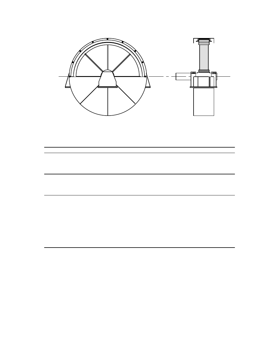
51
Figure 23. Cross-sectional geometry of the low-speed generator.
Table 11. Main data of the 500 kW machines.
Gearless
Gearless
Gearless
Geared
Generator type
Winding
Poles
Speed [rpm]
PM synch.
diamond
80
40
PM synch.
diamond
152
40
PM synch.
single coil
152
40
induction
4
1500
Efficiency [%]
- Generator
- Gear
- Total efficiency
96.0
-
96.0
96.0
-
96.0
91.2
-
91.2
95.6
98.0
93.7
Weight [kg]
Generator
- Active material (Cu+Fe+NdFeB)
- Non-active material
- Stator frame + bearings
- Rotor supporting structure
- Shaft
- Total weight (generator)
Gear
Total weight (generator + gear)
3450
5600
1800
2850
950
9050
-
9050
2950
5350
2100
2400
850
8300
-
8300
3400
5600
1800
2850
950
9000
-
9000
1900
1000
800
200
2900
5100
8000
The efficiency of the conventional PM machine with diamond winding is easy to make higher
than that in the conventional generator-gear solutions. On the other hand, the single-coil winding
machine has high losses in the rotor. The rotor losses should be reduced so that the design would be
more suitable. One way to reduce the eddy-current losses in the rotor is to divide the magnets into
many small parts. Because of the two-dimensional FEM program used, the magnets are modelled as
bars continuous over the length of the machine and, thus, it is not possible to take the effect of the
dividing of the magnets into account.
The active material of the generators in Table 11 includes the electromagnetic part of the
machines, i.e. the winding, the stator and rotor cores and the magnets. The non-active material
includes the other parts of the machine, i.e. the stator frame, the rotor supporting structure, the shaft
and the bearings. The conventional generator-gear solution was optimised by the manufacturer. The

52
design of the non-active part of the low-speed machines is not optimised but calculated like a
design of a large synchronous machine. The total weights of the 500 kW directly driven generators
and the conventional generator-gear solution are between 8000
–
9000 kg. The total weight of the
low-speed machines is a little bit higher than that of the conventional generator-gear solution. The
relative weight of the non-active parts of the low-speed generators is higher than that in the four-
pole induction generator, 62–65% and 33% of the total weight, respectively. One reason for this is
that the low-speed machines must have very strong rotor supporting structures because of the high
torque. The nominal torque of a 500 kW, 40 rpm machine is T
N
= 120 kNm. As a comparison, a
7.5 MW, 600 rpm machine has the same torque. Furthermore, the outer diameter of the low-speed
machines designed is large, 3–3.5 m. The optimisation of the non-active part of the low-speed
machines may decrease the total weight of the low-speed machines.
The wind power plant can be simplified by removing the gear and by using a directly driven
generator. Both types of the PM machines would be available solutions for a directly driven wind
generator. The active material cost of the diamond winding PM machine is lower, but the design is
more complex than that in the single-coil winding PM machine. The gearless design with a low-
speed radial-flux PM generator is a promising design for the wind turbines.

53
5
CONCLUSIONS
The objective of this study has been to investigate the feasibility of low-speed generators for
gearless wind turbines. The investigation is limited to the electromagnetic part of the machine.
According to the analysis, a typical generator-gear solution of the wind power plant can be replaced
by a multipole radial-flux PM synchronous machine.
Two types of radial-flux PM synchronous machines are designed and optimised. The first
machine has a conventional three-phase diamond winding. The second one has an unconventional,
three-phase single-coil winding. The coils are placed in slots around every second tooth, i.e. there is
no overlap in the overhang winding between the coils. High-energy NdFeB magnets are chosen to
be used. These magnets give a sufficient air-gap flux density with a low volume of magnet material.
The rated power of the machines optimised is 500 kW, 10 kW and 5.5 kW. Two prototyp
machines were built and tested.
Various rotor designs of the conventional PM machine were investigated: curved and
rectangular surface-mounted magnets as well as rectangular magnets equipped with pole shoes. The
optimisation shows that the cost of active materials is the lowest and the pull-out torque per the cost
of active materials the highest in the design with curved surface-mounted magnets. If the rotor has
surface-mounted rectangular magnets, they should be divided in parallel parts in each pole. The
advantage of the pole-shoe rotor is that the magnets can be reliably protected mechanically and
magnetically.
The suitable design of the conventional surface-magnet PM machines analysed has a fractional
slot winding. The number of stator slots per pole and phase of this design is q=1.5 and the magnet
width is two thirds of the pole pitch. Then the torque ripple is low, voltage waveform almost
sinusoidal and the efficiency good.
The pull-out torque per cost of active material is higher and the cost of active material smaller in
the conventional PM machine than in the single-coil winding PM machine. The single-coil winding
machine has higher eddy-current losses in the rotor than the conventional machine. On the other
hand, the design of the machine is very simple and the machine is easy to manufacture. The
demagnetisation of permanent magnets is easier to avoid in the single-coil winding machine than in
the conventional design analysed. The cogging torque can be reduced to less than 2% of the rated
torque by choosing a suitable magnet width and the stator slot opening width in both the designs
analysed.
The total weights of the 500 kW directly driven generator and the conventional generator-gea
solution are almost the same. The conventional diamond winding machine is a better choice for the
design of a directly driven wind turbine generator but the single-coil winding machine is also
suitable because of its simplicity.

54

55
REFERENCES
Alatalo, M., Svensson, T. 1993: "Variable Speed Direct-Driven PM Generator with a PWM
Controlled Current Source Inverter," in Proceedings of the European Community Wind Energy
Conference (EWEC'93), Lübeck-Travemünde, Germany, 1993, pp. 639–642.
Anon. 1995–2000: Wind power plant, gearbox and generator manufacturers, brochures and
personal communications.
Anon. 1996: European Wind Turbine Catalogue, European Commission, Brussels, Belgium, 64 p.
Anon. 1999a: Enercon Gearless Wind Power Plants, Enercon GmbH & Co, Aurich, Germany,
brochures.
Anon. 1999b: Lagerwey LW 50/750 Gearless Wind Power Plant, Wistra mbH, Ibbenburen,
Germany, brochures.
Arkkio, A. 1987: "Analysis of Induction Motors Based on the Numerical Solution of the Magnetic
Field and Circuit Equations," Acta Polytechnica Scandinavica, Electrical Engineering Series,
No. 59, Helsinki, Finland, 1987, 97 p., Doctoral thesis.
Arkkio, A. 1990: "Finite Element Analysis of Cage Induction Motors Fed by Static Frequency
Converters," IEEE Transactions on Magnetics, 1990, Vol. 26, No. 2, pp. 551–554.
Arkkio, A., Niemenmaa, A. 1992: "Estimation of Losses in Cage Induction Motors Using Finite
Element Techniques," in Proceedings of the International Conference on Electrical Machines
(ICEM'92), Manchester, U.K., 1992, Vol. 2, pp. 317–321.
Bindner, H., Søndergaard, L.M., Damgaard, E. 1995: "Investigation of Generator Concepts for
Wind Turbines - Summary Report," Risø National Laboratory, Report, No. R-857(DA), Roskilde
Denmark, 15 p., in Danish.
Caricchi, F., Callea, F., Crescimbini, F., Solero, L., Falchetta, M. 1999: "Prototype of Variable-
Speed, Direct-Drive Generator for Wind Power Exploitation in Extremely Cold Climates," in
Proceedings of the European Wind Energy Conference (EWEC'99), Nice, France, 1999, 4 p.
Caricchi, F., Crescimbini, F., Honorati, O., Santini, E. 1992: "Performance Evaluation of an Axial-
Flux PM Generator," in Proceedings of the International Conference on Electrical Machines
(ICEM'92), Manchester, U.K., 1992, Vol. 2, pp. 761–765.
Carlson, O., Grauers, A., Williamson, A., Engström, S., Spooner, E. 1999: "Design and Test of a
40 kW Directly Driven Permanent-Magnet Generator with a Frequency Converter," in
Proceedings
of the European Wind Energy Conference (EWEC'99), Nice, France, 1999, 4 p.
Chalmers, B.J., Spooner, E., Honorati, O., Crescimbini, F., Caricchi, F. 1997: "Compact
Permanent-Magnet Machines," Electric Machines and Power Systems, 1997, Vol. 25, No.
pp. 635–648.
Chen, J., Nayar, C, Xu, L. 1998: "Design and FE Analysis of an Outer-Rotor PM Generator for
Directly-Coupled Wind Turbine Applications," in Proceedings of the IEEE Industry Applications
Conference, New York, USA, 1998, Vol. 1, pp. 387–394.
Deleroi, W. 1992: "Linear Induction Motor in Generation Use for Windmills," in
Proceedings of
the Symposium on Power Electronics, Electrical Drives, Advanced Electrical Motors
(Speedam'92), Positano, Italy, 1992, pp. 71–76.

56
Grauers, A. 1996a: "Design of Direct-Driven Permanent-Magnet Generators for Wind Turbines,"
Chalmers University of Technology, School of Electrical and Computing Engineering, Technical
Report, No. 292, Göteborg, Sweden, 1996, 133 p., Doctoral thesis.
Grauers, A. 1996b: "Generators for Gearless Wind Energy Converters," In
Proceedings of the
European Union Wind Energy Conference and Exhibition, Göteborg, Sweden, 1996, pp. 418–421.
Grauers, A. 1996c: "Directly Driven Wind Turbine Generators," In
Proceedings of the
International Conference on Electrical Machines (ICEM'96), Vigo, Spain, 1996, Vol. 2, pp. 417–
422.
Grauers, A., Carlson, O., Högberg, E., Lundmark, P., Johnsson, M., Svenning, S. 1997: "Test and
Design Evaluation of a 20 kW Direct-driven Permanent-magnet Generator with a Frequency
Converter," in Proceedings of the European Wind Energy Conference (EWEC'97), Dublin, Ireland,
1997, pp. 686–689.
Haouara, I., Tounzi, A., Piriou, F. 1997: "Study of a Variable Reluctance Generator for Wind
Power Conversion," In Proceedings of the 7th European Conference on Power Electronics and
Applications (EPE'97), Brussels, Belgium, 1997, Vol. 2, pp. 631–636.
Haouara, I., Tounzi, A., Piriou, F. 1998: "Design and Optimization of an Excited Reluctance
Generator Using Field Computation," IEEE Transactions on Magnetics, 1998, Vol. 34, No. 5,
pp. 3491–3494.
Hartkopf, T., Hofmann, M., Jöckel, S. 1997: "Direct-Drive Generators for Megawatt Wind
Turbines," In Proceedings of the European Wind Energy Conference (EWEC'97), Dublin, Ireland,
1997, pp. 668–671.
Honorati, O., Caricchi, F., Crescimbini, F., Noia, G. 1991: "Gearless Wind Energy Conversion
System Using an Axial Flux PM Synchronous Machine," In Proceedings of the European Wind
Energy Conference (EWEC'91), Amsterdam, Netherlands, 1991, pp. 814–818.
IEC-34-1, 1994: International Standard, Rotating Electrical Machines, Part 1, Rating and
Performance, International Electrotechnical Commission, Geneve, Switzerland, 1994-03, pp. 37–
39.
Jöckel, S. 1996. "Gearless Wind Energy Converters with Permanent Magnet Generators - An
Option for the Future?" In
Proceedings of the European Union Wind Energy Conference and
Exhibition (EUWEC'96), Göteborg, Sweden, 1996, pp. 414–417.
Kladas, A.G., Papadopoulos, M.P., Tegopoulos, J.A. 1998: "Multipole Permanent Magnet
Generator Design for Gearless Wind Power Applications," In Proceedings of the International
Conference on Electrical Machines (ICEM'98), Istanbul, Turkey, 1998, pp. 2055–2059.
Lampola, P. 1994: "Directly Driven Wind Generators," Chalmers University of Technology,
Department of Electrical Machines and Power Electronics, Technical Report, No. R-94-03,
Göteborg, Sweden, 34 p.
Lampola, P. 1995a: "Directly Driven Generators for Wind Power Applications," In
Proceedings of
the EWEA Special Topic Conference on the Economics of Wind Energy (EWEA 95), Helsinki,
Finland, 1995, pp. 219–224.
Lampola, P. 1995b: "Directly Driven Alternating Current Generators for Wind Power
Applications," Helsinki University of Technology, Laboratory of Electromechanics, Report,
No. 46, Espoo, Finland, 1995, 88 p., Licentiate thesis.
Lampola, P. 1996: "Losses in a Directly Driven, Low-Speed Permanent-Magnet Wind Generator,"
In Proceedings of the Nordic Research Symposium on Energy Efficient Electric Motors and Drives,
Skagen, Denmark, 1996, pp. 358–364.

57
Lampola, P. 1998: "Electromagnetic Design of an Unconventional Directly Driven Permanent-
Magnet Wind Generator," In Proceedings of the International Conference on Electrical Machines
(ICEM'98), Istanbul, Turkey, 1998, Vol. 3, pp. 1705–1710.
Lampola, P. 1999a: "Optimisation of a Directly Driven, Low-Speed Permanent-Magnet Wind
Generator," In Proceedings of the Fourth International Scientific and Technical Conference on
Unconventional Electromechanical and Electrotechnical Systems (UEES'98), St. Petersburg,
Russia, 1999, Vol. 3, pp. 1147–1152.
Lampola, P. 1999b: "Optimisation of Low-Speed Permanent-Magnet Synchronous Machines with
Different Rotor Designs," Electromotion, 1999, Vol. 6, No. 4, pp. 147–159.
Lampola, P. 1999c: "Low-Speed Permanent-Magnet Generators for Gearless Wind Turbines,"
Helsinki University of Technology, Laboratory of Electromechanics, Report, No. 62, Espoo,
Finland, 2000, 24 p.
Lampola, P., Tellinen, J. 1997: "Directly Driven Permanent-Magnet Generator for Wind Power
Applications," In Proceedings of the Europen Wind Energy Conference (EWEC'97), Dublin,
Ireland, 1997, pp. 698–701.
Lampola, P., Perho J., Saari J. 1995: "Electromagnetic and Thermal Design of a Low-Speed
Permanent Magnet Wind Generator," in Proceedings of the IEEE Symposium on Electric Power
Engineering (Stockholm Power Tech), Stockholm, Sweden, 1995, Vol. Electrical Machines and
Drives, pp. 211–216.
Lampola, P., Perho, J., Väänänen, J. 1996a: "Analysis of a Low-Speed Permanent-Magnet Wind
Generator," In Proceedings of the European Union Wind Energy Conference and Exhibition,
Göteborg, Sweden, 1996, pp. 500–503.
Lampola, P., Perho, J., Väänänen, J. 1996b: "Analysis of a Low-Speed Permanent-Magnet Wind
Generator Connected to a Frequency Converter," In Proceedings of the International Conference
on Electrical Machines (ICEM'96), Vigo, Spain, 1996, Vol. 2, pp. 393–398.
Lampola, P., Saari, J., Perho, J. 1997: "Electromagnetic Design of a Low-Speed Surface-Mounted
Permanent-Magnet Wind Generator," Electromotion, 1997, Vol. 4, No. 4, pp. 147–154.
Mellor, P.H., Roberts, D., Turner, D.R. 1991: "Lumped Parameter Thermal Model for Electrical
Machines of TEFC Design," IEE Proceedings, Electric Power Applications, 1991, Vol. 138, No.
pp. 205–218.
Muljadi, E., Butterfield, C.P., Wan, Y-H. 1999: "Axial Flux Modular Permanent-Magnet Generator
with a Toroidal Winding for Wind-Turbine Applications," IEEE Transactions on Industry
Applications, 1999, Vol. 35, No. 4, pp. 831–836.
Palko, S. 1996a: "Structural Optimisation of an Induction Motor Using a Genetic Algorithm and a
Finite Element Method," Acta Polytechnica Scandinavica, Electrical Engineering Series, No. 84
Helsinki, Finland, 1996, 99 p., Doctoral thesis.
Palko, S. 1996b: "Structural Optimisation of Induction Motors Using Time Stepping Method," in
Proceedings of the International Conference on Electrical Machines (ICEM'96), Vigo, Spain,
1996, Vol. 2, pp. 14–19.
Papathanassiou, S.A., Kladas, A.G., Papadopoulos, M.P. 1999: "Direct-Coupled Permanent Magnet
Wind Turbine Design Considerations," In Proceedings of the European Wind Energy Conference
(EWEC'99), Nice, France, 1999, 4 p.
Rasmussen, P., Vilsboll, N., Larsen, A. 1993: "Multipole, Permanent-Magnet Generator Studies
and Planned Prototypes," in Proceedings of the European Community Wind Energy Conference
(EWEC'93), Lübeck-Travemünde, Germany, 1993, pp. 643–645.

58
Søndergaard, L.M., Bindner, H. 1995: "Investigation of Generator Concepts for Wind Turbines -
Direct Driven Generators for Gearless Wind Turbines," Risø National Laboratory, Report, No. R
-
801(DA), Roskilde, Denmark, 52 p., in Danish.
Spooner, E., Williamson, A.C. 1992: "The Feasibility of Direct-Coupled Permanent-Magnet
Generators for Wind Power Applications," in Proceedings of the Symposium on Power Electronics,
Electrical Drives, Advanced Electrical Motors (Speedam'92), Positano, Italy, 1992, pp. 105–112.
Spooner, E., Williamson, A.C. 1996: "Direct-Coupled, Permanent-Magnet Generators for Wind
Turbine Applications," IEE Proceedings, Electric Power Applications, 1996, Vol. 143, No. 1,
pp. 1–8.
Spooner, E., Williamson, A.C. 1998: "Parasitic Losses in Modular Permanent-Magnet Generators,"
IEE Proceedings, Electric Power Applications, 1998, Vol. 145, No. 6, pp. 485–496.
Spooner, E., Williamson, A.C, Catto, G. 1994: "Braking of PM, Direct-Coupled Wind Turbine
Generators," in Proceedings of the International Conference on Electrical Machines (ICEM'94),
Paris, France, 1994, Vol. 3, pp. 239–243.
Spooner, E., Williamson, A.C., Catto, G. 1996: "Modular Design of Permanent-Magnet Generators
for Wind Turbines," IEE Proceedings, Electric Power Applications, 1996, Vol. 143, No. 5,
pp. 388–395.
Stiebler, M., Okla, O. 1992: "A Permanent Magnet Toroid Wind Generator," in
Proceedings of the
International Conference on Electrical Machines (ICEM'92), Manchester, U.K., 1992, Vol. 3,
pp. 1043–1047.
Söderlund, L., Eriksson, J-T., Salonen, J., Vihriälä, H., Perälä, R. 1996: "A Permanent-Magnet
Generator for Wind Power Applications," IEEE Transactions on Magnetics, 1996, Vol. 32, No. 4,
pp. 2389–2392.
Söderlund, L., Perälä, R. 1997: "Comparison of Direct Driven Axial and Radial Flux Permanent
Magnet Generators for Wind Power Applications," in Proceedings of the International Conference
on Magnet Technology, Beijing, China, 1997, 4p.
Tellinen, J., Jokinen, T. 1996: "Permanent Magnet Machine for a Training Device," In
Proceedings
of the International Conference on Electrical Machines (ICEM'96), Vigo, Spain, 1996, Vol. 2,
pp. 299–302.
Tellinen, J., Lampola, P., Jokinen, T. 1996: "Low-Speed Permanent Magnet Machine with High-
Torque Capacity," In Proceedings of the Second International Scientific and Technical Conference
on Unconventional Electromechanical and Electrotechnical Systems (UEES'96), Szczecin, Poland,
1996, Vol. 2, pp. 377–382.
Torrey, D., Hassanin, M. 1995: "The Design of Low-Speed Variable-Reluctance Generators," In
Proceedings of the IEEE Industry Applications Conference, New York, USA, 1995, Vol. 1, pp.
427–433.
Yildirim, D., Fuchs, E.F., Batan, T. 1998: "Test Results of a 20 kW Variable-Speed Direct-Drive
Wind Power Plant," In Proceedings of the International Conference on Electrical Machines
(ICEM'98), Istanbul, Turkey, 1998, pp. 2039–2044.
Veltman, A.T., Souille, P.P., de Haan, S.W.H., Thijssen, G.H.C.M. 1996: "Cost-Performance of
Direct Drive Wind Turbine Generators," In Proceedings of the European Union Wind Energy
Conference and Exhibition, Göteborg, Sweden, 1996, pp. 410–413.
Väänänen, J. 1992: "Calculation of Electric and Thermal Properties of a Permanent-Magnet High-
Speed Electrical Motor," Helsinki University of Technology, Laboratory of Electromechanics,
Report, No. 34, Espoo, Finland, 1992, 93 p., Master of Science thesis, in Finnish.

59
Väänänen, J. 1994a: "Construction of a Power Electronic Simulator Including Two-Dimensional
Finite Element Modelling of Electrical Machines", Electrical Engineering, Archiv für
Elektrotechnik, 1994, Vol. 78, No. 1, pp. 41–50.
Väänänen, J. 1994b: "Combination of Power Electronic Models with the Two-Dimensional Finite
Element Analysis of Electrical Machines," in Proceedings of the International Conference on
Electrical Machines (ICEM'94), Paris, France, 1994, Vol. 3, pp. 99–104.
Väänänen, J. 1995: "Combination of Two-Dimensional Finite Element Analysis of Electrical
Machines with Circuit Simulation Techniques," Acta Polytechnica Scandinavica, Electrical
Engineering series, No. 80, Helsinki, Finland, 1995, 104 p., Doctoral thesis
Weh, H. 1992: "Drive Concept with New Machines," in
Proceedings of the Symposium on Power
Electronics, Electrical Drives, Advanced Electrical Motors (Speedam'92), Positano, Italy, 1992,
pp. 29–35.
Weh, H. 1995: "Transverse-Flux Machines in Drive and Generator Application," in
Proceedings of
the IEEE Symposium on Electric Power Engineering (Stockholm Power Tech), Stockholm,
Sweden, 1995, Vol. Invited speakers' session, pp. 75–80.
Weh, H., Hoffmann, H., Landrath, J. 1988: "Directly Driven Permanent Magnet Excited
Synchronous Generator for Variable Speed Operation," in Proceedings of the European Community
Wind Energy Conference (EWEC'88), Herning, Denmark, 1988, pp. 566–572.
Williamson, S., Volschenk, A. F. 1995: "Time-Stepping Finite Element Analysis for a Synchronous
Generator Feeding a Rectifier Load," IEE Proceedings, Electric Power Applications, 1995,
Vol. 142, No. 1, pp. 50–56.
Zielinski, P., Schoepp, K. 1992: "Three-Ph Low Speed Permanent Magnet Synchronous
Machines," in Proceedings of the International Conference on Electrical Machines (ICEM'92),
Manchester, U.K., 1992, Vol. 3, pp. 1034–1038.
von Zweygbergk, S. 1990: "Permanent-Magnet Synchronous Machine Based on the Transversal-
Flux Principle with High Power Density," Chalmers University of Technology, Department of
Electrical Machines, Report, No. 5, Göteborg, Sweden, 1990, 30 p., in Swedish.
von Zweygbergk, S. 1992: "Permanent Magnetized Synchronous Machine Designed According to
the Transverse Flux Principle," US patent, No. 5.117.142, 26 May 1992, 11 p.

60
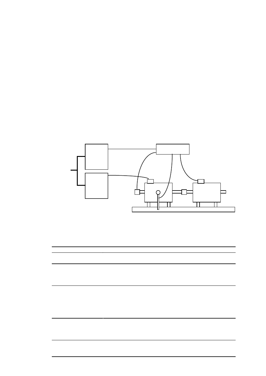
61
APPENDIX LABORATORY
SET-UP
Measurement of the conventional PM machine
The laboratory set-up used for testing the PM machine is shown in Fig. 1 and the equipments in
Table 1. The PM machine was fed by a PWM frequency converter. A power analyser wa
connected between the converter and the PM machine. The experimental machine was
mechanically connected to a DC machine. The DC machines were controlled by a grid-connecte
thyristor rectifier. The mechanical torque was measured by a torque transducer and the rotational
speed by a tachometer. The cogging torque was measured with a torque transducer by rotating the
machine at a speed of 2.4 rpm. The amplified signal was drawn by a plotter. The voltage harmonic
were measured by a frequency analyser. The voltage vaweform was measured and drawn by using
LEM LV 100 voltage sensors and a plotter.
PM
machine
DC machine
Measurements
PWM
converter
Tacho-
meter
Torque
measurement
400 V
AC
Thyristor
rectifier
Figure 1. Laboratory set-up.
Table 1. Equipments used in the experiments.
Equipment
PM machine supply
Vacon/KCI Konecranes DYNAC V 400 F, PWM converter
- 520 kVA, 380–500 V, 750 A
Loading
Kone MG31EC200, DC machine
- 180 kW, 400 V, 450 A, 1000 rpm
Strömberg SMEK 380A150, thyristor rectifier
- 150 kW, 400 V, 350 A
Electrical quantities
NORMA 6133M, power analyser
- 1000 V, sampling rate 35–75 kHz
LEM LT 500-S, current sensor, 500 A
LEM LV 100, voltage sensor, 10 mA
Hioki 8803 FFT Hi Corder, plotter
Spectral dynamic SD340, micro FFT frequency analyser
Mechanical torque
and speed
Raute precision TB2-1t-F, torque transducer
- 10 000 N
Raute ELC2, amplifier
Tachometer
Cogging torque
Raute TB3, torque transducer
- 2000 N
Maywood D2000, amplifier
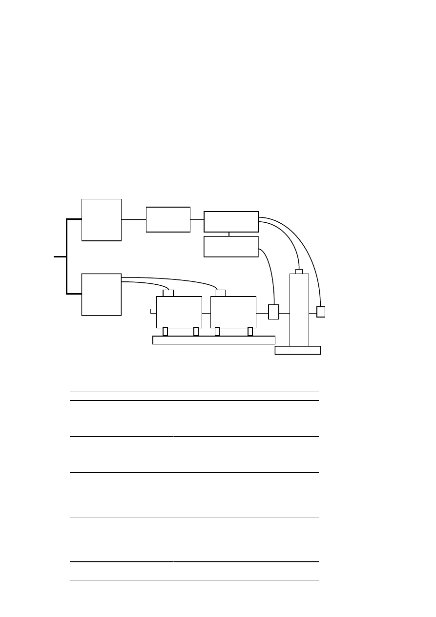
62
Measurement of the single-coil winding PM machine
The laboratory set-up used for testing the PM machine is shown in Fig. 2 and the equipments in
Table 2. The PM machine was fed by a three-phase autotransformer. A synchronosscope and a
power analyser was connected between the transformer and the PM machine. The experimental
machine was mechanically connected to a DC machine via a torque transducer. Two serial
connected 45 kW, 1500 rpm, DC machines were used as a load machine in order to get high
enough load torque. The DC machines were controlled by a grid-connected thyristor rectifier. The
cogging torque was measured with a small weighing by rotating the machine slowly. The voltage
harmonics were measured by a transient recorder.
Measurements
Tacho-
meter
Torque
measurement
400 V
AC
DC
machine
T
Synchronos-
scope
Auto-
transformer
PM
m
a
c
h
i
n
e
DC
machine
Thyristor
rectifier
Figure 2. Laboratory set-up.
Table 2. Equipments used in the experiments.
Equipment
PM machine supply
Kemppi, autotransformer
- 19 kVA, 0–400 V, 27 A
Gossen, synchronosscope
- 400 V, 50 Hz
Loading
Strömberg GNAU/E, DC machine
- 45 kW, 220 V, 205 A, 1500 rpm
Veritron AAD 7001, thyristor rectifier
- 180 kW, 485 V, 375 A DC
Electrical quantities
NORMA 6100, power analyser
- 1000 V
- Norma triax shunts, 30 A
- Sampling rate 35–75 kHz
Kontron 700, transient recorder
Mechanical torque and
speed
HBM T30FN, torque transducer
- 1000 Nm, 3000 rpm
HBM MD18N, signal amplifier
Leine & Linde, tachometer
- 1000 pulse / turn
Cogging torque
Weighing
- 1 kg
Wyszukiwarka
Podobne podstrony:
A Low Speed, High Torque, Direct Drive Permanent Magnet Generator For Wind Turbines
(Wind) A Low Speed, High Torque, Direct Drive Permanent Magnet Generator For Wind Turbines
Design Of Direct Driven Permanent Magnet Generators For Wind Turbines
Control Issues Of A Permanent Magnet Generator Variable Speed Wind Turbine
Abb 3,5Mw Permanent Magnet Generator
Adjustable Speed Generators For Wind Turbines Based On Doubly
Vector Controlled Doubly Fed Induction Generator for Wind Applications
A Composite Pwm Method Of Three Phase Voltage Source Inverter For High Power Applications
[2000] A Flywheel Switched Reluctance Motor Drive for Wind Energy Applications
Home Power Magazine Issue 063 Extract p42 Solar charge controller for Medium Power Applications
A Composite Pwm Method Of Three Phase Voltage Source Inverter For High Power Applications
Development Of Wind Power Control System For Six Phase Permanent Magnet Synchronous Generators
[2003] Constant Voltage Permanent Magnet Wind Generator
[2006] Analysis of a Novel Transverse Flux Generator in direct driven wind turbine
Auto Sign an automatic signature generator for high speed malware filtering devices
więcej podobnych podstron