
Initial Print Date: 12/04
Table of Contents
Subject
Page
Navigation Computer (NAV. 01) . . . . . . . . . . . . . . . . . . . . . . . . . . . . . . . . . .5
GPS Antenna . . . . . . . . . . . . . . . . . . . . . . . . . . . . . . . . . . . . . . . . . . . . . . . . . .6
Speed Signal . . . . . . . . . . . . . . . . . . . . . . . . . . . . . . . . . . . . . . . . . . . . . . . . . . .6
MOST . . . . . . . . . . . . . . . . . . . . . . . . . . . . . . . . . . . . . . . . . . . . . . . . . . . . . . . .6
RGB Lines . . . . . . . . . . . . . . . . . . . . . . . . . . . . . . . . . . . . . . . . . . . . . . . . . . . . .6
Navigation Display . . . . . . . . . . . . . . . . . . . . . . . . . . . . . . . . . . . . . . . . . . . . . .7
New Functions . . . . . . . . . . . . . . . . . . . . . . . . . . . . . . . . . . . . . . . . . . . . . . . . .8
New Route . . . . . . . . . . . . . . . . . . . . . . . . . . . . . . . . . . . . . . . . . . . . . . . . . .8
Avoiding Toll Road . . . . . . . . . . . . . . . . . . . . . . . . . . . . . . . . . . . . . . . . . . . .8
Selection of Destination from Stored Memory . . . . . . . . . . . . . . . . . . .8
Display of Navigation Data in the Instrument Cluster . . . . . . . . . . . . . .8
Extended Voice Instructions . . . . . . . . . . . . . . . . . . . . . . . . . . . . . . . . . . .9
Direct Home Function . . . . . . . . . . . . . . . . . . . . . . . . . . . . . . . . . . . . . . . .9
Avoiding Sections of a Road or Complete Roads . . . . . . . . . . . . . . . . .9
E65 Navigation System
Revision Date:

2
E65 Navigation System
E65 Navigation System
Model: E65/E66
Production: All
After completion of this module you will be able to:
• Understand the operation of the E65 navigation system.
• Understand the differences between the previous navigation systems
Introduction
The navigation computer of the E65 is the control unit that provides navigation, telemat-
ics and Online services (planned).
In terms of the functionality, the navigation computer corresponds to the Mk-3 navigation
computer introduced for model year 2001. A number of additional functions however,
have been integrated.
• New, larger screen (8.8 inches) with an 8:3 size ratio.
• Simultaneous map and arrow presentation modes.
• Map or arrow presentation in assistance window always possible (simultaneously
with radio menu, etc.).
• New-route calculation is faster when the driver has to deviate from the planned
route.
• Improved map presentation graphics.
• Faster on-screen map builds.
• "Avoiding toll road" as a new routing criteria.
• Multiple destinations can be grouped in a destinations list and picked up one after
the other.
• Route information arrows, distance and name of the next street shown in the
instrument cluster.
• Extended voice output ("... follow the I95 interstate").
• Direct destination home (also by voice command).
• Avoiding individual roads or entire roadway sections.
• Help text explanations for individual menu items.
Like all information and communication systems, the control unit is connected to the
MOST bus.
3
E65 Navigation System
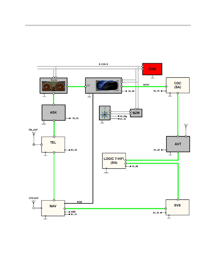
System Overview
4
E65 Navigation System
Components
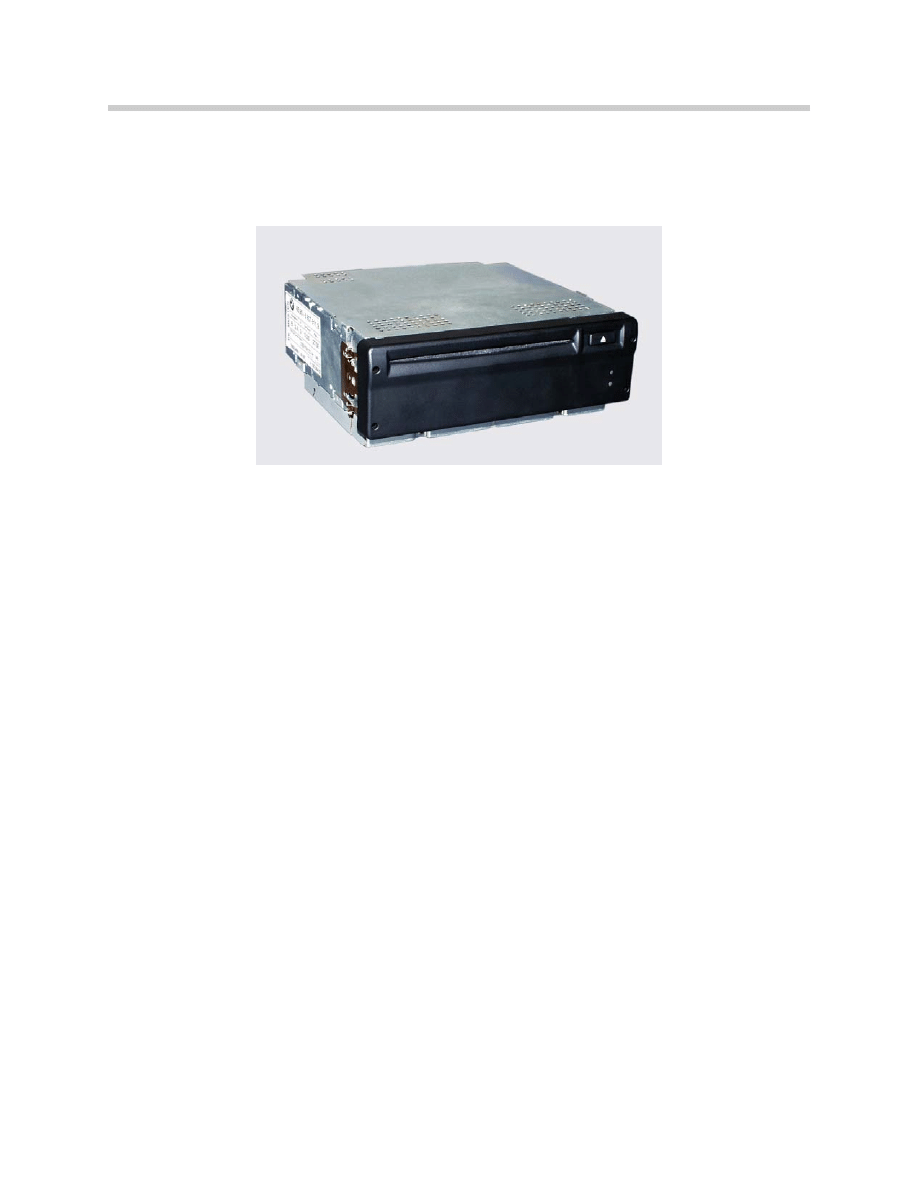
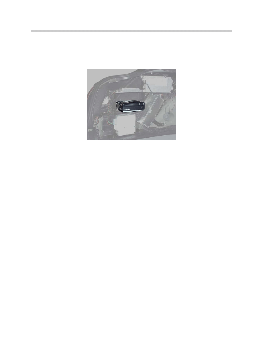
Navigation Computer (NAV. 01)
The navigation computer is located in the left rear corner of the luggage compartment.
Similar to the Mk-3 computer, the E65 NAV. 01 contains:
• CD drive.
• Hardware for navigation, telematics and online services function.
• Transceiver for interface with the MOST network. (Transceiver contains two nodes)
• Gyro sensor.
• GPS receiver.
• Output for RGB (graphics interface)
• Cooling fan for unit.
Building maps on the Control Display is now considerably faster than before. This
improvement was achieved by means of modifications to the hardware.
The connection to the MOST bus is by a standardized MOST transceiver. The MOST
transceiver incorporates two interfaces (nodes).
Each MOST telegram is divided into 3 parts.
• Control data
• Asynchronous data (e.g. navigation system, arrow presentation)
• Synchronous data (e.g. audio, video signals)
A node can analyze only two signals at a time, this is the reason why two nodes are nec-
essary for the navigation computer. In the Control Display self-test, both nodes are
shown as control units but only one node can be displayed as a recognized control unit.
The second node is always displayed as "wait" (normally control unit not recognized).
5
E65 Navigation System
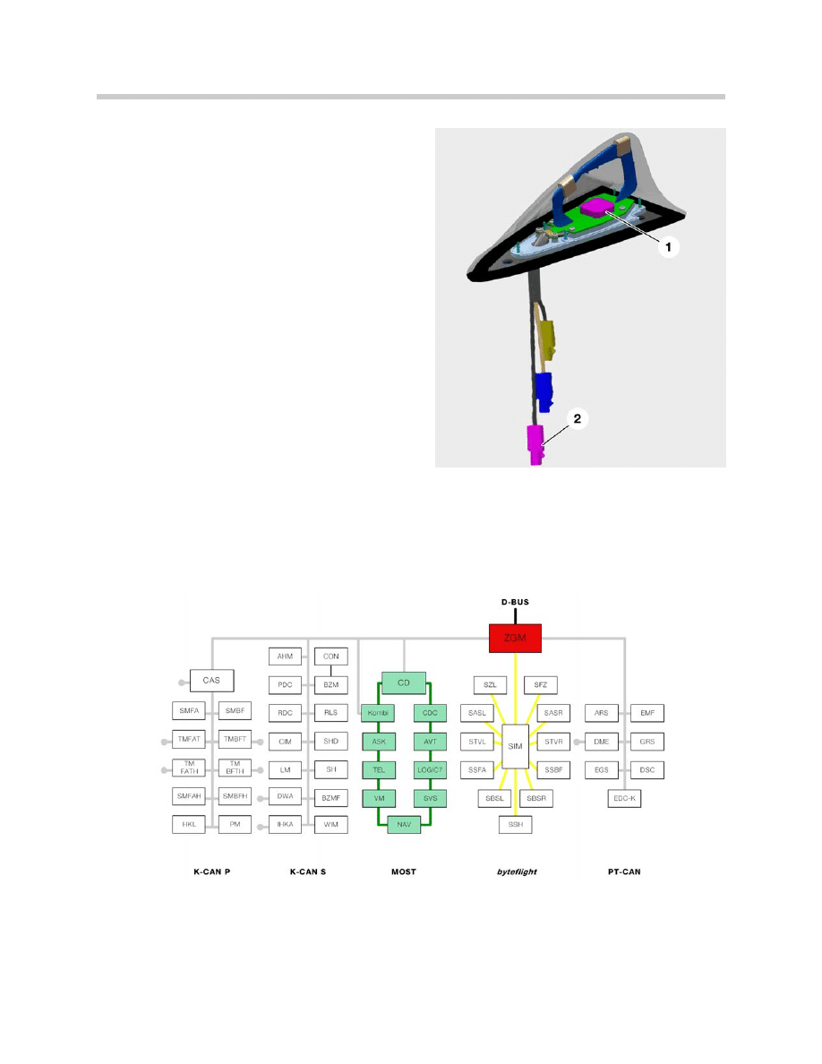
GPS Antenna
The antenna for the navigation system is incor-
porated into the shark-fin antenna that is
mounted on the roof.
This antenna contains a dual band antenna for
the telephone as well as the GPS antenna.
Speed Signal
The road speed signal is provided directly by
the DSC. The signal is processed from the left
front wheel sensor.
MOST
The navigation computer is part of the MOST
network. Like all the control units in the MOST
system, the navigation computer is woken up
by light signals on the MOST bus, this means
that the nav. computer has to be in permanent
operation.
Standby current consumption is less than 0.02 mA.
The data for the route arrows displayed in the instrument cluster and in the Control
Display is carried on the MOST bus.
RGB Lines
The navigation computer sends the signal for map display directly to the Control Display
along separate RGB lines.
6
E65 Navigation System
1.GPS antenna
2.GPS connector
Principle of Operation
Navigation Display
The information is presented in the Control Display
and the instrument cluster. The display window in the
Control Display has been re-sized to a width-to-
height ratio of 8:3 (previous wide-screen BM 16:9).
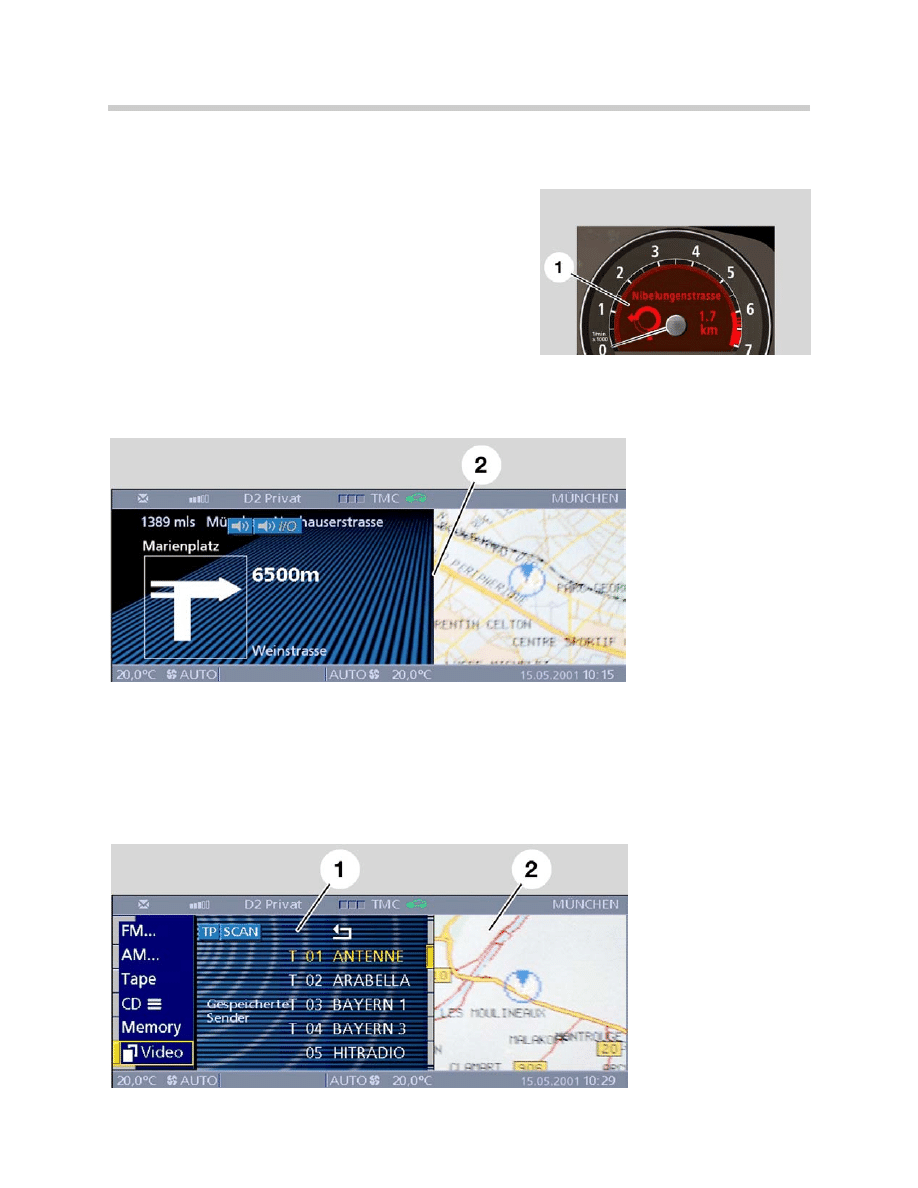
When Route Guidance (with arrow display selected)
is active, the navigation display also appears auto-
matically in the instrument cluster.
Display of the information in the instrument cluster cannot be deactivated while the route
guidance function is active.
The display of navigation information in the Control Display can be deactivated by select-
ing some other function.
Map or arrow display in assistance window is always possible (simultaneously with radio
menu, BC, etc.)
7
E65 Navigation System
2. Arrow display in control
area and map in assis-
tance screen of control
display
1. Entertainment menu in
control area
2. Map in assistance screen
New Functions
New Route
New-route calculation is faster when the driver has to deviate from the planned route.
Instead of recalculating the entire route when the driver deviates from the planned route,
the computer re-calculates only a section of the route before issuing the next instruction,
this saves time.
Avoiding Toll Road
This is a new selection that has been added to the route-selection menu along with the
previous: fastest route, main use of highways, least use of highways, etc.).
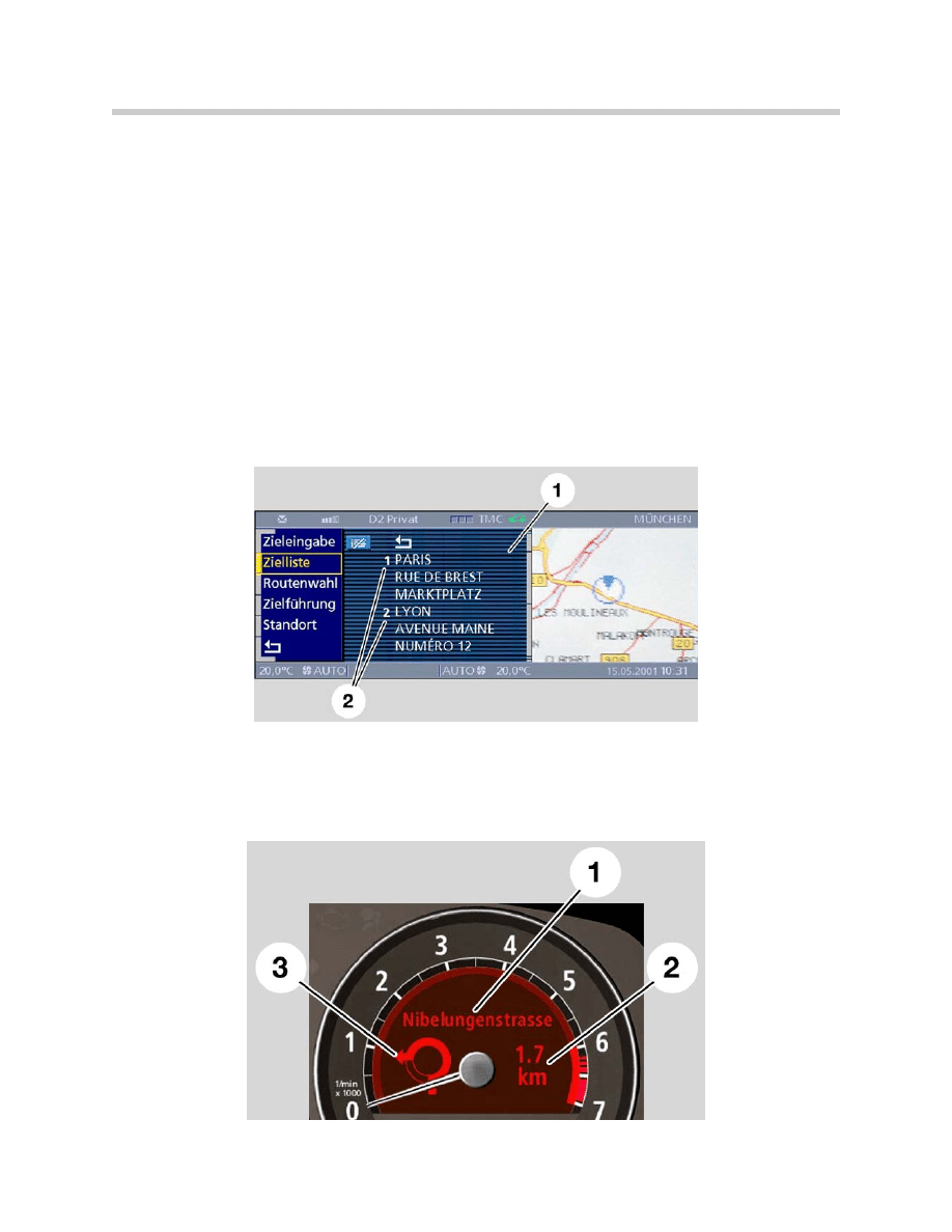
Selection of Destination from Stored Memory
Multiple destinations are stored in a destinations list. To select the current desired route
from memory, the destination must be selected and placed as number 1.
Display of Navigation Data in the Instrument Cluster
Route information, distance and the name of the next street can now be shown in the
instrument cluster providing the driver with navigation data without having to look away
from the road.
8
E65 Navigation System
1. Destinations list
2. Destinations 1 & 2
1. Street name
2. Distance until
next turn
3. Route arrow
Extended Voice Instructions
The voice instructions have a greater vocabulary thanks to the faster processor and
greater system memory of the navigation computer. (e.g. “Continue straight ahead fol-
lowing I95”, instead of, “follow the main road”).
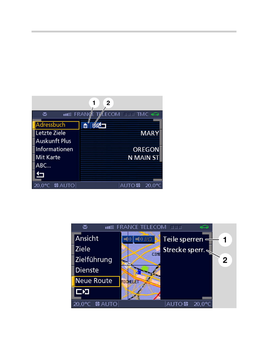
Direct Home Function
Selecting home is easier by storing it permanently in memory and selecting it from a
“home” icon in the address book menu or using the Speech Processing System to
access it.
Avoiding Sections of a Road or Complete Roads
From the New Route menu individual roads or complete roadways can be barred and the
navigation computer will develop a new route avoiding those specific roads. This is espe-
cially useful to avoid long term construction sites or roads that are commonly congested
with traffic.
9
E65 Navigation System
1. Avoid section
2. Avoid route
1. Home icon, used to select change
and enter home address
2. Button for deleting destinations in
destination list

Classroom Exercise - Review Questions
1. Where is the antenna for the navigation system located?
2. How many “nodes” are integrated in to the navigation computer? Why does it
have that many? How can this affect troubleshooting a MOST bus problem?
3. How does the navigation computer send display images to the Control Display
and the instrument cluster?
10
E65 Navigation System
Document Outline
- Main Menu
- Intro to Advanced Body Electronics
- E65 Power Module
- E65 Car Access System
- E65 Instrument Cluster
- E65 iDrive Driving Area
- E65 iDrive Comfort Area
- E65 Audio System
- E65 Navigation System
- E65 Telephone
- E65 Speech Processing System
- E65 Central Body Electronics
- E65 Remote Control Services
- E65 Automatic Trunk Lid Lift
- E65 Wiping Washing
- E65 Seat, Mirror, Steering Wheel
- E65 Lighting Systems
- E65 Driveaway Protection
- E65 Park Distance Control
- E65 Active Cruise Control
- Voltage Supply and Bus Systems
- 5 & 6 Series Body Electronics
- E60 Driver Information Systems
- E60 Communication Systems
- Car Communication Computer
- Head-Up Display
- Glossary
Wyszukiwarka
Podobne podstrony:
10 E65 Navigation System
09 E65 Audio System
04a E65 Audio System
BMW Navigation System FAQ
Audi A4 Radio navigation system (RNS D) 2002
Audi A4 Navigation system (NS LOW) 2001
0775 TPI 2023632 15 Radio Navigation System RNS850 No VIN
06 E65 Lighting Systems
Group 22B Navigation System
Radio navigation system MFD CD changer and TV tuner wiring
Navigation and Audio System
05 E65 Car Access System
04b E70 Lateral Dynamics Systems
12 E65 Speech Processing System
02b E65 Car Access System
04d E65 Speech Processing System
więcej podobnych podstron