41075–01
–
MANUAL TRANSMISSION/TRANSAXLE
MANUAL TRANSAXLE SYSTEM
41–1
1401
Author:
Date:
2004 COROLLA (RM1037U)
MANUAL TRANSAXLE SYSTEM
PROBLEM SYMPTOMS TABLE
Use the table below to help you find the cause of the problem. The numbers indicate the priority of the likely
cause of the problem. Check each part in order. If necessary, replace parts.
Symptom
Suspect Area
See page
Noise
6. Oil (Level low)
7. Oil (Wrong)
8. Gear (Worn or damaged)
9. Bearing (Worn or damaged)
41–2
41–2
41–63
41–74
41–63
41–74
Oil leakage
1. Oil (Level too high)
2. Gasket (Damaged)
3. Oil seal (Worn or damaged)
4. O–Ring (Worn or damaged)
41–2
41–28
41–3
41–28
Hard to shift or will not shift
1. Control cable (Faulty)
2. Synchronizer ring (Worn or damaged)
3. Shifting key spring (Damaged)
41–9
41–12
41–63
41–74
41–63
41–74
Jumps out of gear
1. Locking ball spring (Damaged)
2. Gear Shift fork (Worn)
3. Gear (Worn or damaged)
4. Bearing (Worn or damaged)
41–28
41–28
41–63
41–74
41–63
41–74
41076–01
D25304
0 – 5 mm
(0 – 0.20 in.)
41–2
–
MANUAL TRANSMISSION/TRANSAXLE
MANUAL TRANSAXLE OIL
1402
Author:
Date:
2004 COROLLA (RM1037U)
MANUAL TRANSAXLE OIL
ON–VEHICLE INSPECTION
1.
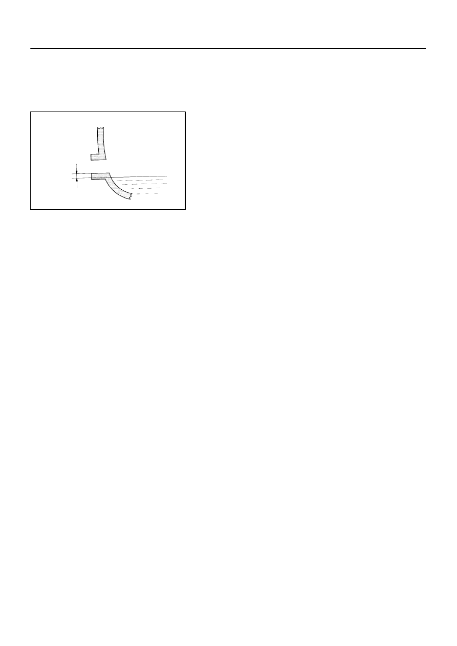
INSPECT TRANSAXLE OIL
(a)
Stop the vehicle on the level place.
(b)
Remove the transmission filler plug and gasket.
(c)
Check that the oil surface is within 5 mm (0.20 in.) from the
lowest position of the inner surface of the transmission fill-
er plug opening.
NOTICE:
Excessively large or small amount of oil may cause
troubles.
After replacing oil, drive the vehicle and check the oil
level.
(d)
Check for oil leakage when the oil level is low.
(e)
Install the transmission filler plug and new gasket.
Torque: 39.2 N
⋅
m (400 kgf
⋅
cm, 29 ft
⋅
lbf)
41077–02
C94266
SST
D25305
SST
D25722
SST
–
MANUAL TRANSMISSION/TRANSAXLE
FRONT DIFFERENTIAL OIL SEAL
41–3
1403
Author:
Date:
2004 COROLLA (RM1037U)
FRONT DIFFERENTIAL OIL SEAL
REPLACEMENT
1.
DRAIN MANUAL TRANSAXLE OIL
Torque: 39.2 N
⋅
m (400 kgf
⋅
cm, 29 ft
⋅
lbf)
2.
REMOVE FRONT WHEELS
3.
REMOVE ENGINE UNDER COVER LH
4.
REMOVE ENGINE UNDER COVER RH
5.
DRAIN TRANSAXLE OIL
6.
REMOVE FRONT DRIVE SHAFT ASSY LH (See page
30–6
)
SST
09520–01010, 09520–24010 (09520–32040)
7.
REMOVE FRONT DRIVE SHAFT ASSY RH (See page
30–6
)
SST
09520–01010, 09520–24010 (09520–32040)
8.
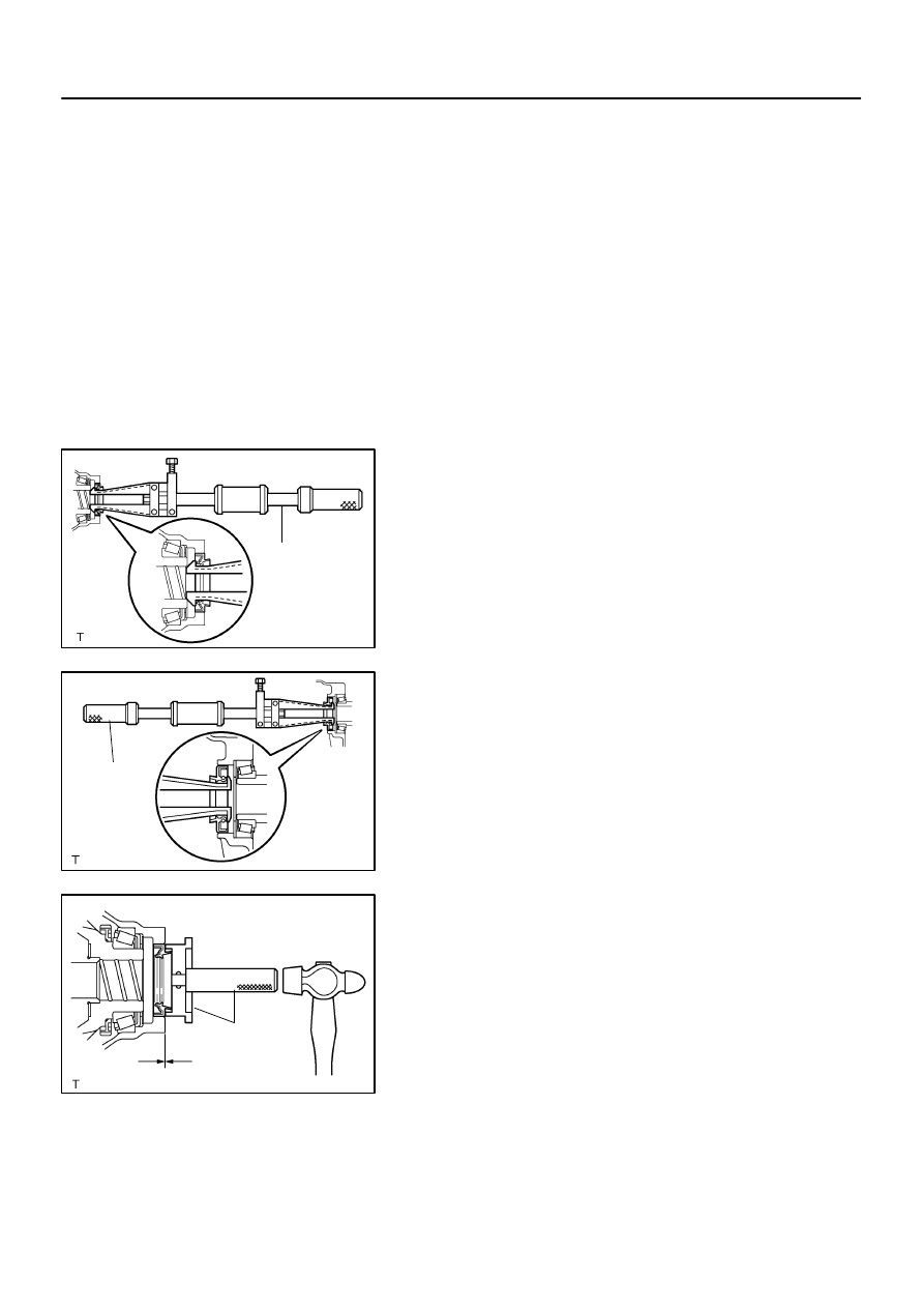
REMOVE TRANSAXLE CASE OIL SEAL
(a)
Using SST, remove the transaxle case oil seal.
SST
09308–00010
9.
REMOVE TRANSMISSION CASE OIL SEAL
(a)
Using SST, remove the transmission case oil seal.
SST
09308–00010
10.
INSTALL TRANSAXLE CASE OIL SEAL
(a)
Coat a new oil seal lip with MP grease.
(b)
Using SST and a hammer, install the transaxle case oil
seal.
SST
09554–14010, 09950–70010 (09951–07200)
Drive in depth: 1.9
0.3 mm (0.075
0.012 in.)
NOTICE:
Be careful not to damage the oil seal lip.
D26133
SST
D25304
0 – 5 mm
(0 – 0.20 in.)
41–4
–
MANUAL TRANSMISSION/TRANSAXLE
FRONT DIFFERENTIAL OIL SEAL
1404
Author:
Date:
2004 COROLLA (RM1037U)
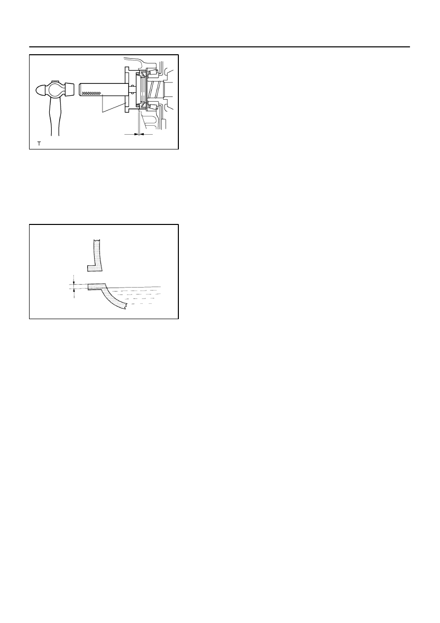
11.
INSTALL TRANSMISSION CASE OIL SEAL
(a)
Coat a new oil seal lip with MP grease.
(b)
Using SST and a hammer, install the transmission case
oil seal.
SST
09554–14010, 09950–70010 (09951–07200)
Drive in depth: 9.9
0.3 mm (0.390
0.012 in.)
NOTICE:
Be careful not to damage the oil seal lip.
12.
INSTALL FRONT DRIVE SHAFT ASSY LH (See page
30–6
)
13.
INSTALL FRONT DRIVE SHAFT ASSY RH (See page
30–6
)
14.
INSTALL FRONT WHEELS
Torque: 103 N
⋅
m (1,050 kgf
⋅
cm, 76 ft
⋅
lbf)
15.
ADD MANUAL TRANSAXLE OIL
Oil grade: API GL–4 or GL–5
Viscosity: SAE 75 W–90
Capacity:1.9 liters (2.0 US qts, 1.7 lmp. qts)
Torque: 39.2 N
⋅
m (400 kgf
⋅
cm, 29 ft
⋅
lbf)
16.
INSPECT AND ADJUST MANUAL TRANSAXLE OIL (See page
41–2
)
17.
INSPECT AND ADJUST FRONT WHEEL ALIGNMENT (See page
26–5
)
18.
CHECK ABS SPEED SENSOR SIGNAL (See page
05–297
)
4107A–01
B53749
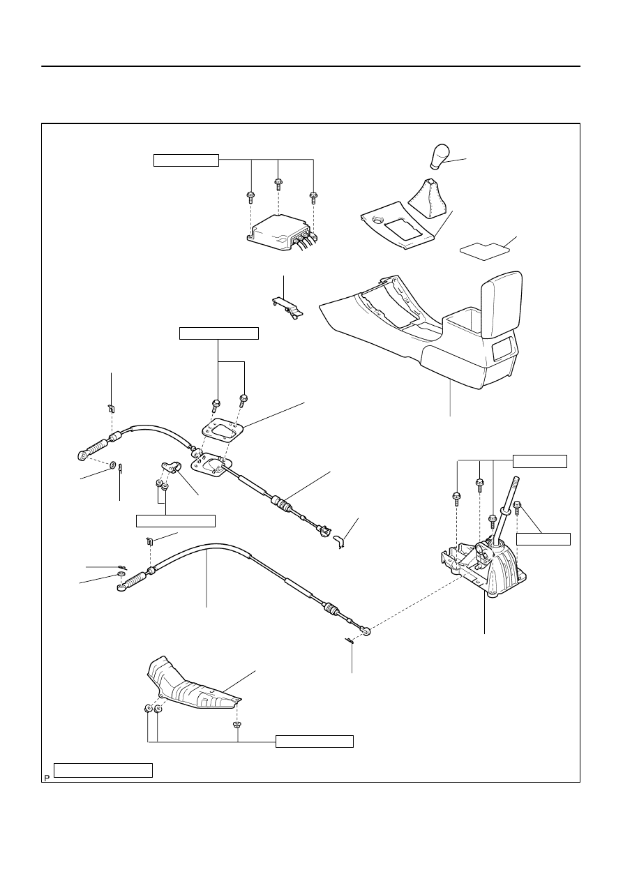
Parking Brake Hole Cover Sub–assy
Floor Shift Lever
Knob Sub–assy
Console Box Carpet
Console Panel Upper
Shift Cable Grommet
Retainer No. 1
Floor Shift Cable Transmission
Control Shift
Floor Shift Cable Transmission
Control Select
Clip
Floor Shift Shift Lever Assy
Console Box Sub–assy Rear
Clip
: Specified torque
N
⋅
m (kgf
⋅
cm, ft
⋅
lbf)
Clip
Clamp
Clip
Clip
Front Floor Heat Insulator
Washer
Clip
Washer
12 (122, 9)
17.5 (178, 13)
5.5 (56, 49 in.
⋅
lbf)
12 (122, 9)
5.0 (51, 44 in.
⋅
lbf)
5.0 (51, 44 in.
⋅
lbf)
–
MANUAL TRANSMISSION/TRANSAXLE
FLOOR SHIFT SHIFT LEVER ASSY
41–5
1405
Author:
Date:
2004 COROLLA (RM1037U)
FLOOR SHIFT SHIFT LEVER ASSY
COMPONENTS
4107B–01
D26974
D26973
Cable Outer
Spring
Lock
D26976
D26975
Cable Outer
spring
Lock
41–6
–
MANUAL TRANSMISSION/TRANSAXLE
FLOOR SHIFT SHIFT LEVER ASSY
1406
Author:
Date:
2004 COROLLA (RM1037U)
REPLACEMENT
HINT:
COMPONENTS: See page
41–5
1.
REMOVE FLOOR SHIFT SHIFT LEVER KNOB SUB–ASSY
2.
REMOVE CONSOLE PANEL UPPER (See page
71–10
)
3.
REMOVE PARKING BRAKE HOLE COVER SUB–ASSY (See page
71–10
)
4.
REMOVE CONSOLE BOX SUB–ASSY REAR (See page
71–10
)
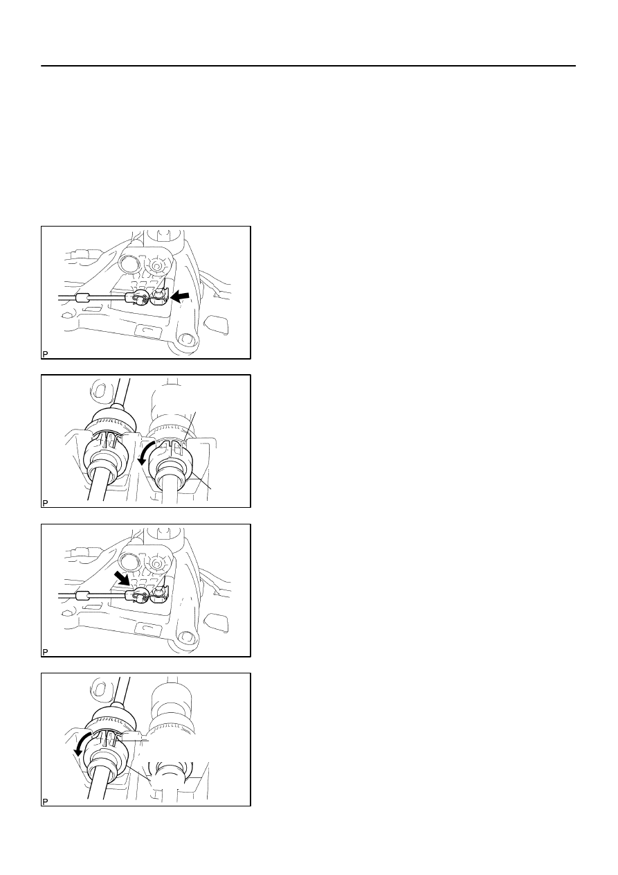
5.
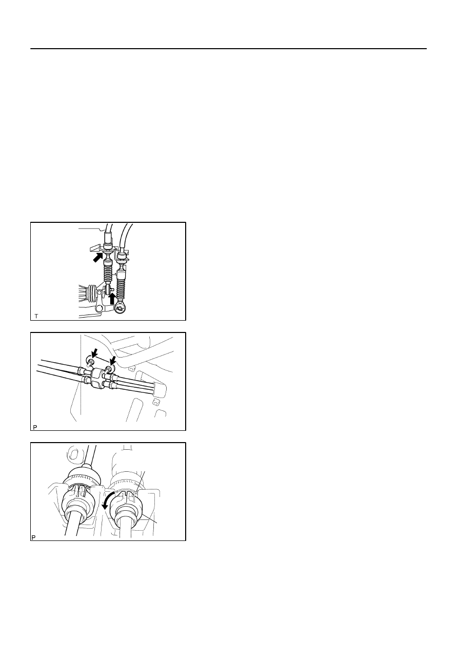
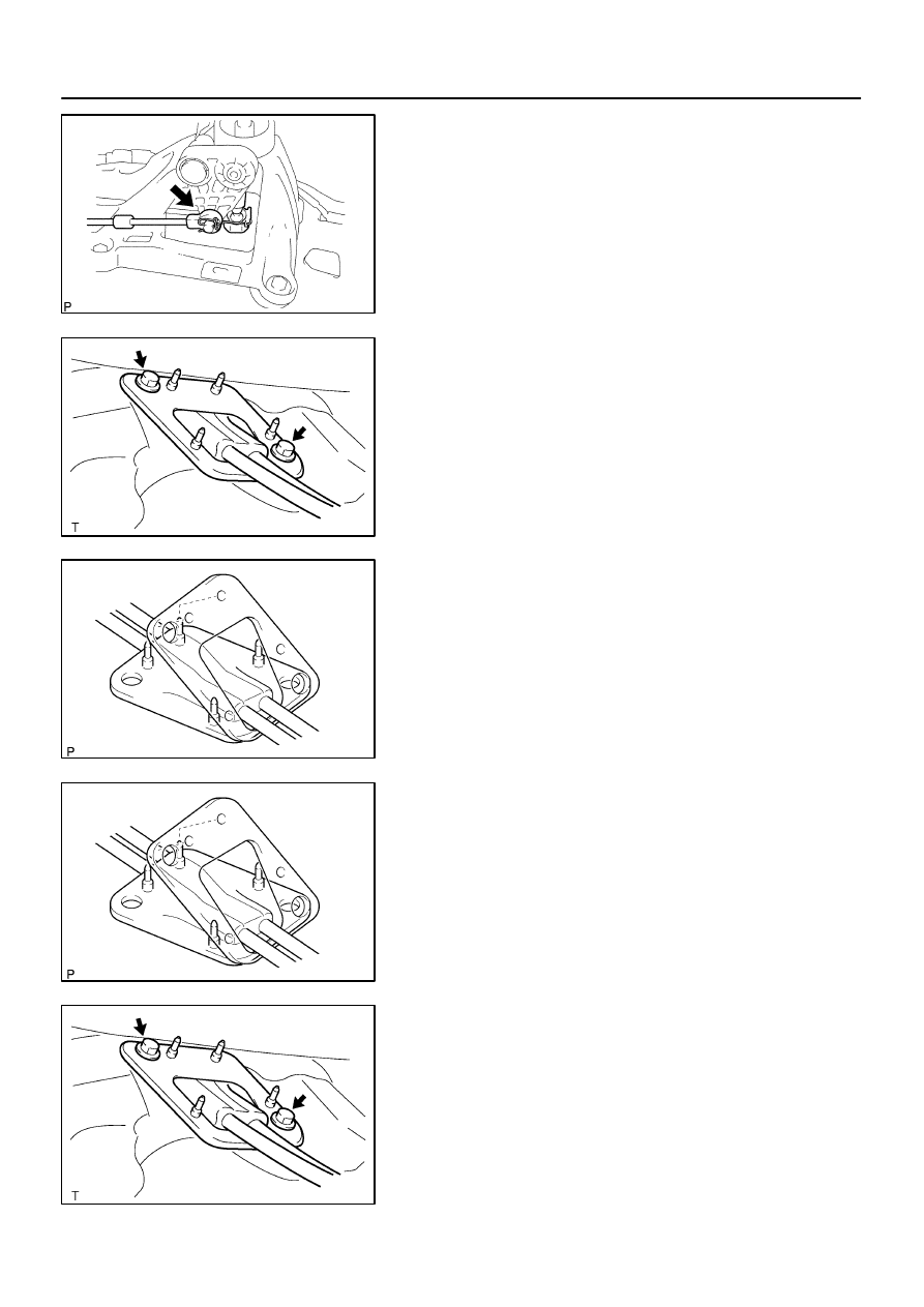
SEPARATE FLOOR SHIFT CABLE TRANSMISSION
CONTROL SHIFT
(a)
Separate the end of the shift cable from the shift lever
assy.
(b)
Using a screwdriver, release the cable outer spring.
(c)
Turn the lock, separate the shift cable from the shift lever
retainer.
6.
SEPARATE FLOOR SHIFT CABLE TRANSMISSION
CONTROL SELECT
(a)
Separate the end of the select cable from the shift lever
assy.
(b)
Using a screwdriver, release the cable outer spring.
(c)
Turn the lock, separate the select cable from the shift le-
ver retainer.
D26889
D26889
D26915
Cable Outer
spring
Lock
D26974
–
MANUAL TRANSMISSION/TRANSAXLE
FLOOR SHIFT SHIFT LEVER ASSY
41–7
1407
Author:
Date:
2004 COROLLA (RM1037U)
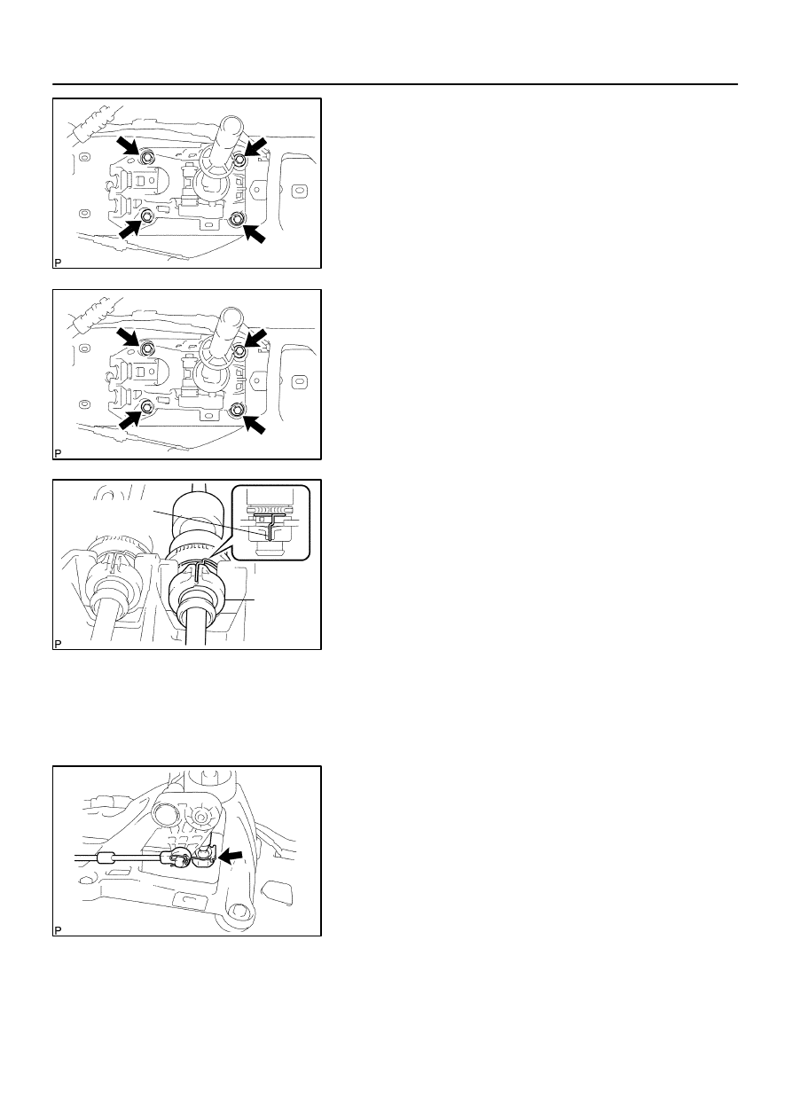
7.
REMOVE FLOOR SHIFT SHIFT LEVER ASSY
(a)
Remove the 4 bolts and shift lever assy.
8.
INSTALL FLOOR SHIFT SHIFT LEVER ASSY
(a)
Install the shift lever assy with the 4 bolts.
Torque: 12 N
⋅
m (120 kgf
⋅
cm, 9 ft
⋅
lbf)
9.
CONNECT FLOOR SHIFT CABLE TRANSMISSION
CONTROL SHIFT
(a)
Connect the shift cable to the retainer of shift lever assy,
turn the lock.
NOTICE:
The projecting part of the lock should face upward when
the shift cable is installed.
(b)
Install the cable outer spring to the lock.
NOTICE:
Make sure that after installation the cable outer spring is
moved to the place shown in the illustration.
(c)
Connect the end of the shift cable to the shift lever assy.
D26916
Cable Outer
spring
Lock
D26976
41–8
–
MANUAL TRANSMISSION/TRANSAXLE
FLOOR SHIFT SHIFT LEVER ASSY
1408
Author:
Date:
2004 COROLLA (RM1037U)
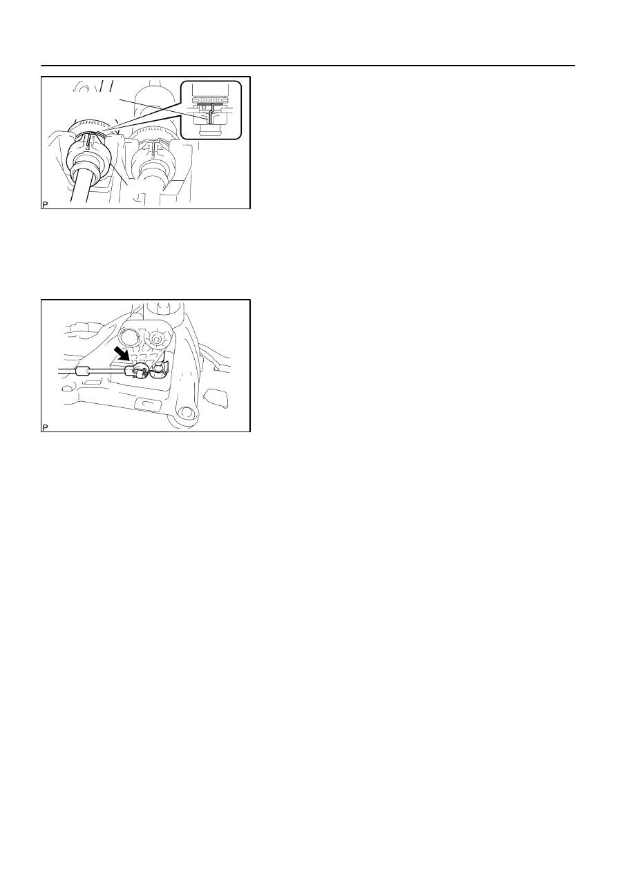
10.
CONNECT FLOOR SHIFT CABLE TRANSMISSION
CONTROL SELECT
(a)
Connect the select cable to the retainer of shift lever assy,
turn the lock.
NOTICE:
The projecting part of the lock should face upward when
the select cable is installed.
(b)
Install the cable outer spring to the lock.
NOTICE:
Make sure that after installation the cable outer spring is
moved to the place shown in the illustration.
(c)
Connect the end of the select cable to the shift lever assy.
41078–02
D26696
B53753
D26973
Cable Outer
Spring
Lock
–
MANUAL TRANSMISSION/TRANSAXLE
FLOOR SHIFT CABLE TRANSMISSION CONTROL
SHIFT
41–9
1409
Author:
Date:
2004 COROLLA (RM1037U)
FLOOR SHIFT CABLE TRANSMISSION CONTROL SHIFT
REPLACEMENT
HINT:
COMPONENTS: See page
41–5
1.
REMOVE AIR CONDITIONER UNIT ASSY (See page
55–17
)
HINT:
Refer to the instructions for removal of the air conditioner unit assy.
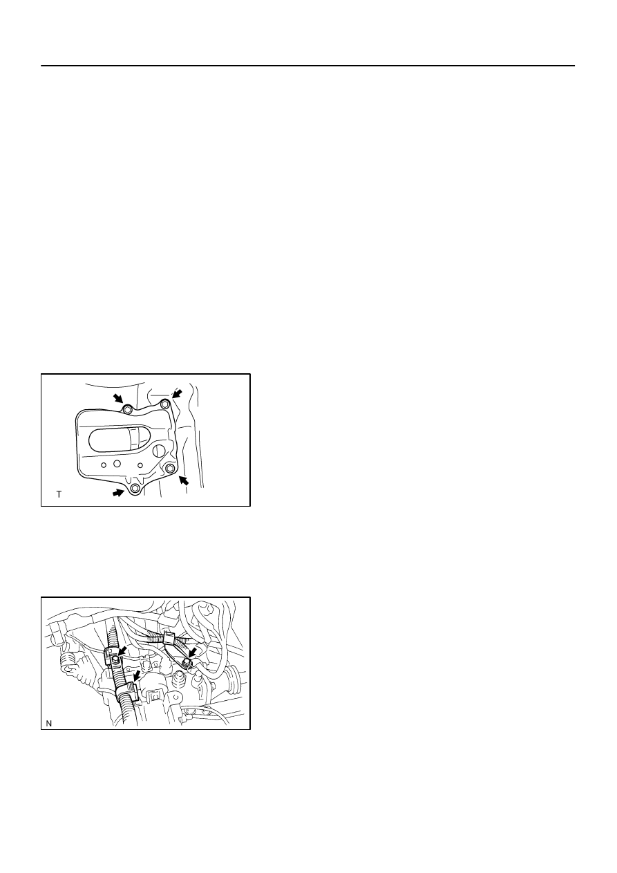
2.
SEPARATE AIR BAG SENSOR ASSY CENTER
(a)
Remove the 3 bolts, separate the airbag sensor assy center.
3.
REMOVE EXHAUST PIPE ASSY (See page
15–2
)
4.
REMOVE FRONT FLOOR HEAT INSULATOR NO.1
(a)
Remove the 3 nuts and heat insulator No.1.
5.
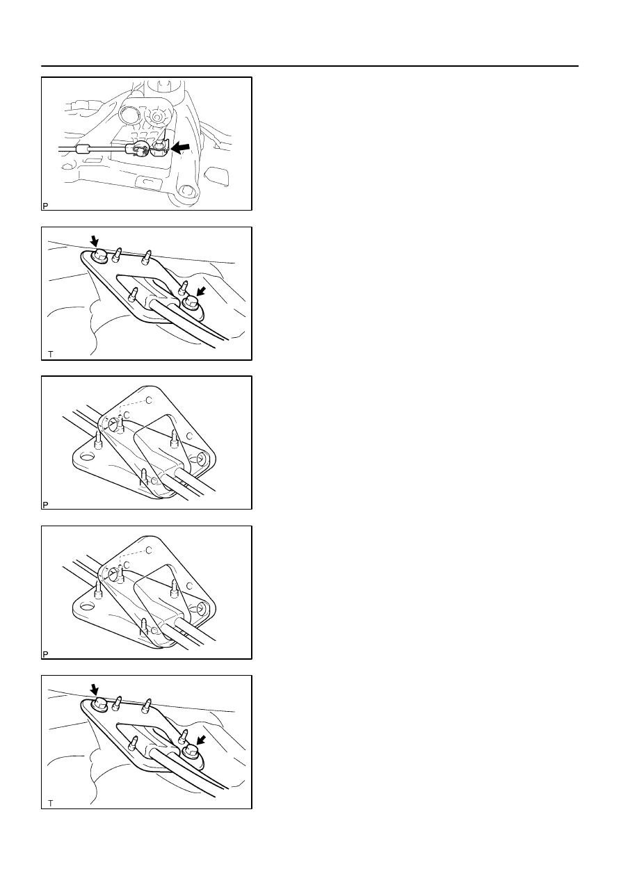
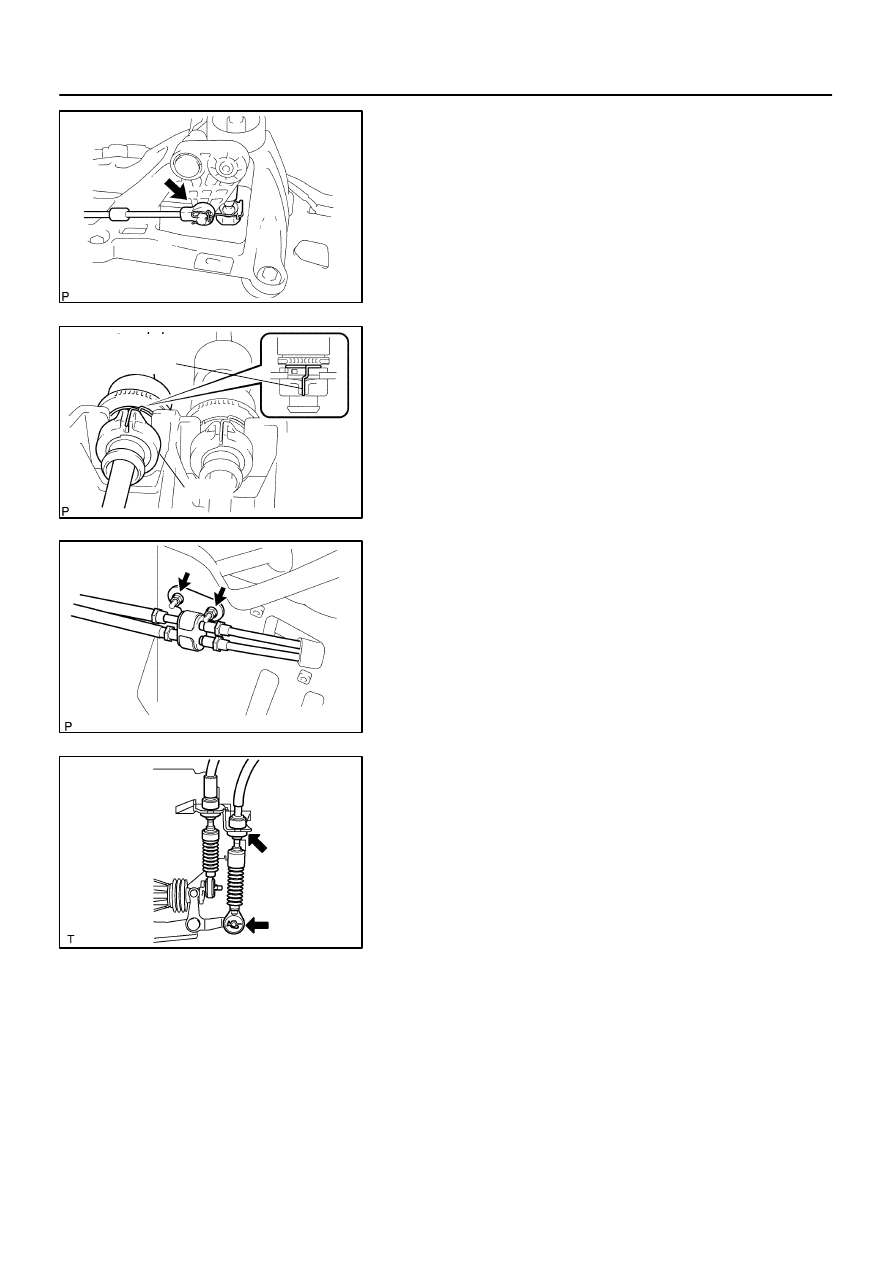
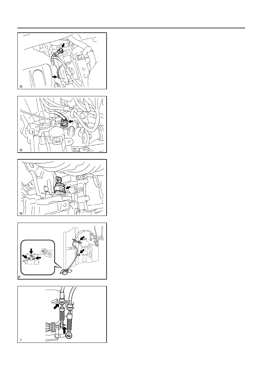
REMOVE FLOOR SHIFT CABLE TRANSMISSION
CONTROL SHIFT
(a)
Remove the clip and washer, separate the top of the shift
cable from the transaxle.
(b)
Remove the clip, separate the shift cable from the control
cable bracket.
(c)
Remove the 2 nuts and clamp.
(d)
Using a screwdriver, release the cable outer spring.
(e)
Turn the lock, separate the shift cable from the shift lever
retainer.
D26974
D26966
B53750
B53750
D26966
41–10
–
MANUAL TRANSMISSION/TRANSAXLE
FLOOR SHIFT CABLE TRANSMISSION CONTROL
SHIFT
1410
Author:
Date:
2004 COROLLA (RM1037U)
(f)
Separate the end of the shift cable from the shift lever
assy.
(g)
Remove the 2 bolts and retainer from the floor.
(h)
Pull out the control cable assy from the floor.
(i)
Remove the retainer from the grommet.
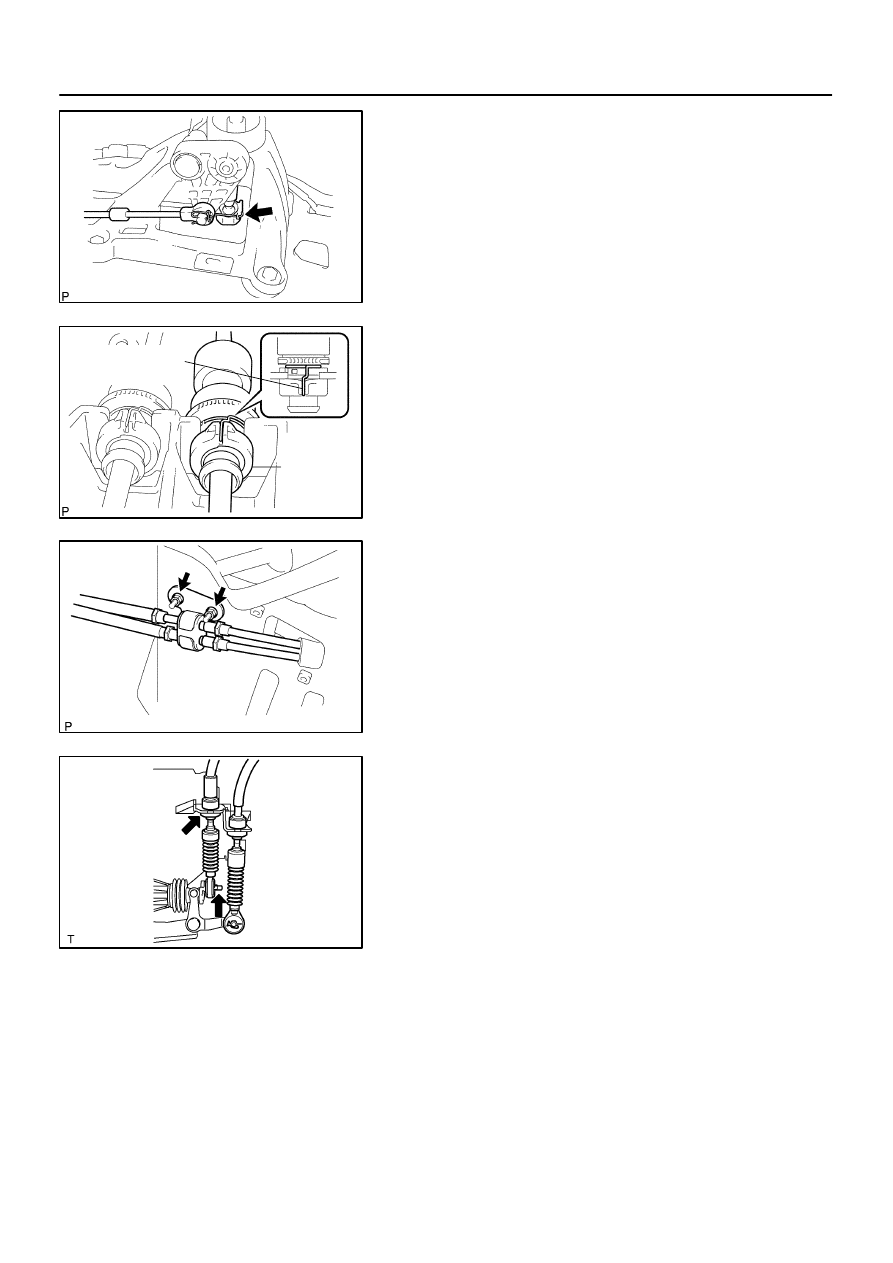
6.
INSTALL FLOOR SHIFT CABLE TRANSMISSION
CONTROL SHIFT
(a)
Put the control cable assy through the floor hole and re-
tainer.
(b)
Install the retainer to the grommet.
NOTICE:
Fit 4 projections of the grommet into 4 holes of the retainer.
(c)
Install the control cable assy with the 2 bolts.
Torque: 5.0 N
⋅
m (51 kgf
⋅
cm, 44 in.
⋅
lbf)
D26974
D26915
Cable Outer
Spring
Lock
B53753
D26696
–
MANUAL TRANSMISSION/TRANSAXLE
FLOOR SHIFT CABLE TRANSMISSION CONTROL
SHIFT
41–11
1411
Author:
Date:
2004 COROLLA (RM1037U)
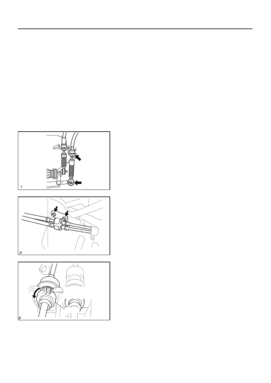
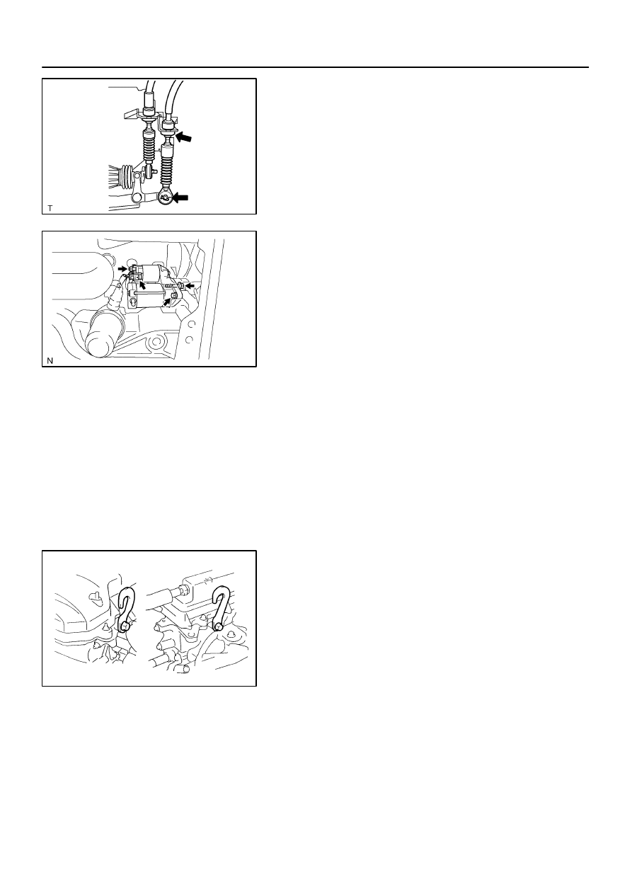
(d)
Connect the end of the shift cable to the shift lever assy.
(e)
Connect the shift cable to the retainer of shift lever assy,
turn the lock.
NOTICE:
The projecting part of the lock should face upward when
the shift cable is installed.
(f)
Install the cable outer spring to the lock.
NOTICE:
Make sure that after installation the cable outer spring is
moved to the place shown in the illustration.
(g)
Install the clamp with the 2 nuts.
Torque: 5.0 N
⋅
m (51 kgf
⋅
cm, 44 in.
⋅
lbf)
(h)
Connect the shift cable to the control cable bracket, install
a new clip.
(i)
Connect the shift cable to the transaxle, install the washer
and clip.
7.
INSTALL FRONT FLOOR HEAT INSULATOR NO.1
(a)
Install the heat insulator No.1 with the 3 nuts.
Torque: 5.5 N
⋅
m (56 kgf
⋅
cm, 49 in.
⋅
lbf)
8.
INSTALL EXHAUST PIPE ASSY (See page
15–2
)
9.
CONNECT AIR BAG SENSOR ASSY CENTER
(a)
Install the airbag sensor assy center with the 3 bolts.
Torque: 17.5 N
⋅
m (178 kgf
⋅
cm, 13 ft
⋅
lbf)
10.
INSPECT SRS WARNING LIGHT (See page
05–424
)
41079–02
D26968
B53753
D26975
Cable Outer
Spring
Lock
41–12
–
MANUAL TRANSMISSION/TRANSAXLE
FLOOR SHIFT CABLE TRANSMISSION CONTROL
SELECT
1412
Author:
Date:
2004 COROLLA (RM1037U)
FLOOR SHIFT CABLE TRANSMISSION CONTROL SELECT
REPLACEMENT
HINT:
COMPONENTS: See page
41–5
1.
REMOVE AIR CONDITIONER UNIT ASSY (See page
55–17
)
HINT:
Refer to the instructions for removal of the air conditioner unit assy.
2.
SEPARATE AIR BAG SENSOR ASSY CENTER
(a)
Remove the 3 bolts, separate the airbag sensor assy center.
3.
REMOVE EXHAUST PIPE ASSY (See page
15–2
)
4.
REMOVE FRONT FLOOR HEAT INSULATOR NO.1
(a)
Remove the 3 nuts and heat insulator No.1.
5.
REMOVE FLOOR SHIFT CABLE TRANSMISSION
CONTROL SELECT
(a)
Remove the clip and washer, separate the top of the se-
lect cable from the transaxle.
(b)
Remove the clip, separate the select cable from the con-
trol cable bracket.
(c)
Remove the 2 nuts and clamp.
(d)
Using a screwdriver, release the cable outer spring.
(e)
Turn the lock, separate the select cable from the shift le-
ver retainer.
D26976
D26966
B53750
B53750
D26966
–
MANUAL TRANSMISSION/TRANSAXLE
FLOOR SHIFT CABLE TRANSMISSION CONTROL
SELECT
41–13
1413
Author:
Date:
2004 COROLLA (RM1037U)
(f)
Separate the end of the select cable from the shift lever
assy.
(g)
Remove the 2 bolts and retainer from the floor.
(h)
Pull out the control cable assy from the floor.
(i)
Remove the retainer from the grommet.
(j)
Remove the select cable from the grommet.
6.
INSTALL FLOOR SHIFT CABLE TRANSMISSION
CONTROL SELECT
(a)
Install the select cable to the grommet.
(b)
Install the retainer to the grommet.
NOTICE:
Fit 4 projections of the grommet into 4 holes of the retainer.
(c)
Install the control cable assy with the 2 bolts.
Torque: 5.0 N
⋅
m (51 kgf
⋅
cm, 44 in.
⋅
lbf)
D26976
D26916
Lock
Cable Outer
Spring
B53753
D26968
41–14
–
MANUAL TRANSMISSION/TRANSAXLE
FLOOR SHIFT CABLE TRANSMISSION CONTROL
SELECT
1414
Author:
Date:
2004 COROLLA (RM1037U)
(d)
Connect the end of the select cable to the shift lever assy.
(e)
Connect the select cable to the retainer of shift lever assy,
turn the lock.
NOTICE:
The projecting part of the lock should face upward when
the select cable is installed.
(f)
Install the cable outer spring to the lock.
NOTICE:
Make sure that after installation the cable outer spring is
moved to the place shown in the illustration.
(g)
Install the clamp with the 2 nuts.
Torque: 5.0 N
⋅
m (51 kgf
⋅
cm, 44 in.
⋅
lbf)
(h)
Connect the select cable to the control cable bracket,
install a new clip.
(i)
Connect the select cable to the transaxle, install the
washer and clip.
7.
INSTALL FRONT FLOOR HEAT INSULATOR NO.1
(a)
Install the heat insulator No.1 with the 3 nuts.
8.
INSTALL EXHAUST PIPE ASSY (See page
15–2
)
9.
CONNECT AIR BAG SENSOR ASSY CENTER
(a)
Install the airbag sensor assy center with the 3 bolts.
Torque: 17.5 N
⋅
m (178 kgf
⋅
cm, 13 ft
⋅
lbf)
10.
INSPECT SRS WARNING LIGHT (See page
05–424
)
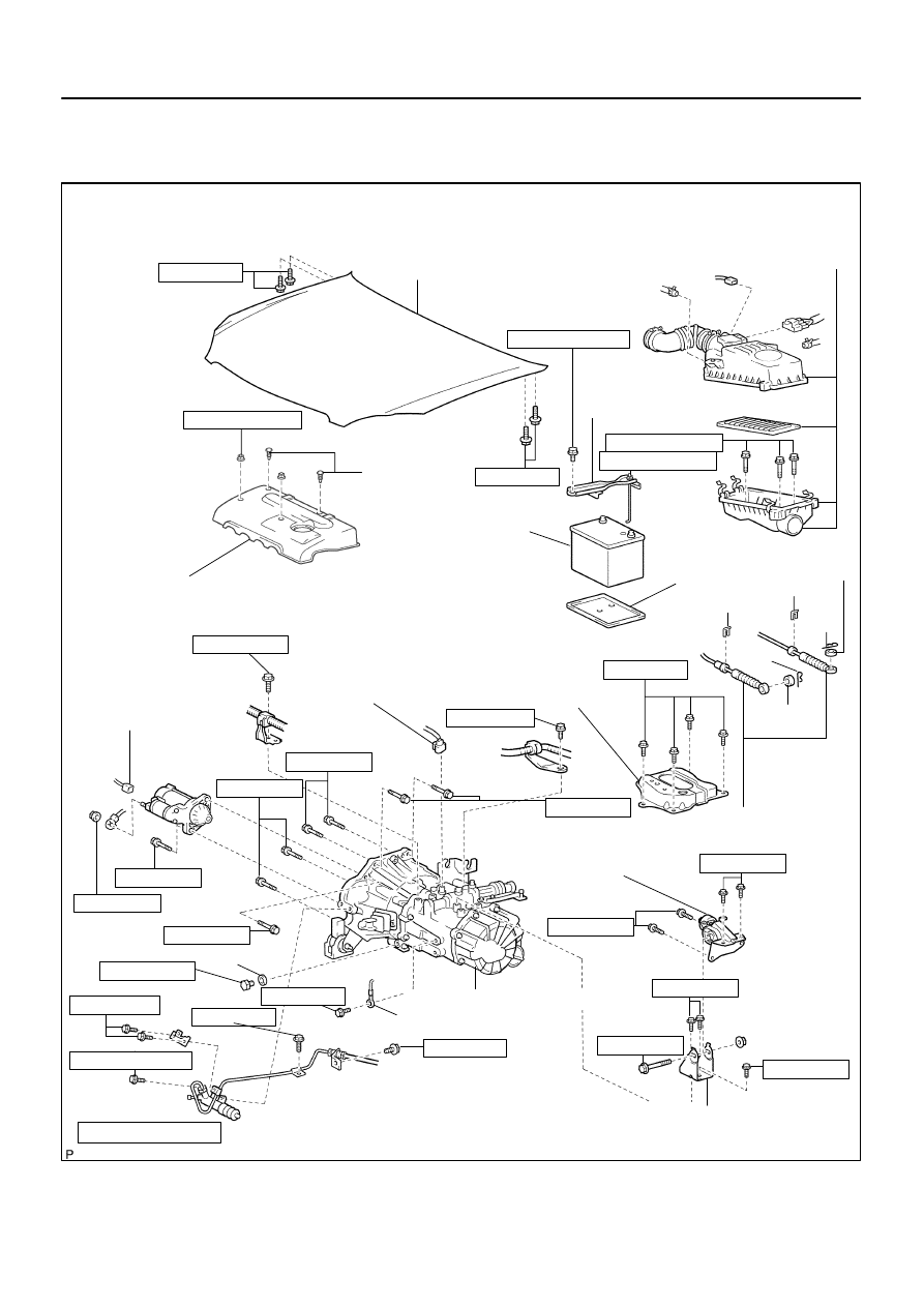
4107C–01
B53751
13 (133, 10)
Hood Sub–assy
Cylinder Head
Cover No. 2
Clip
7.0 (71, 62 in.
⋅
lbf)
Battery
Battery Clamp
Sub–assy
Battery Tray
Washer
Floor Shift Transmission
Control Cable Assy
Clip
Air Cleaner Assy
Clip
Clip
Clip
Washer
5.0 (51, 44 in.
⋅
lbf)
3.5 (36, 31 in.
⋅
lbf)
7.0 (71, 62 in.
⋅
lbf)
13 (133, 10)
N·m (kgf·cm, ft·lbf) : Specified torque
Non–reusable part
Transverse Engine
Engine Mounting Bracket
Transverse Engine
Engine Mounting Insulator
52 (530, 38)
Manual Transaxle Assy
80 (816, 59)
Ground Cable
64 (650, 47)
52 (530, 38)
52 (530, 38)
25 (250, 19)
52 (530, 38)
Battery Carrier
12.8 (131, 9)
Back–up Lamp Switch
Connector
25.5 (260, 19)
13 (133, 10)
25 (250, 19)
47 (480, 35)
23 (230, 17)
37 (378, 27)
37 (378, 27)
12.8 (131, 9)
Starter Connector
Gasket
Filler Plug
39.2 (400, 29)
11.8 (120, 9)
5.0 (51, 44 in.
⋅
lbf)
13 (133, 10)
–
MANUAL TRANSMISSION/TRANSAXLE
MANUAL TRANSAXLE ASSY
41–15
1415
Author:
Date:
2004 COROLLA (RM1037U)
MANUAL TRANSAXLE ASSY
COMPONENTS
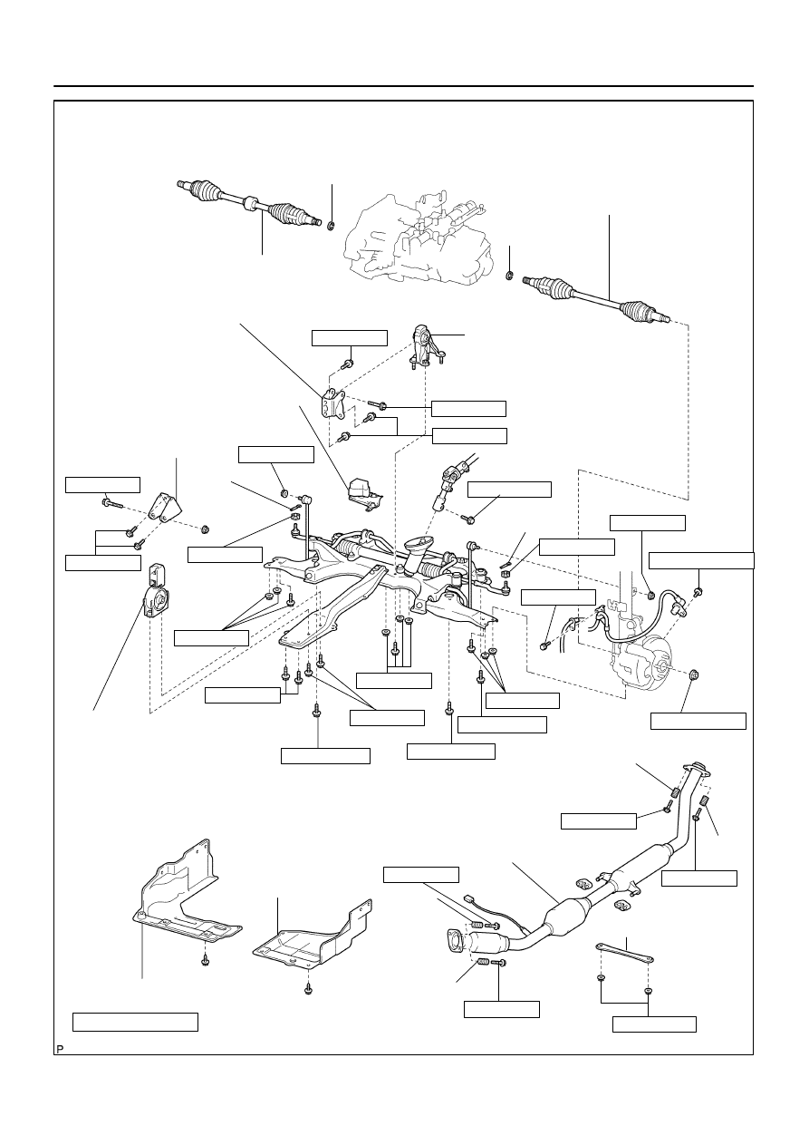
B53752
Front Drive Shaft Assy RH
Snap Ring
Front Drive Shaft Assy LH
Snap Ring
64 (653, 47)
Transverse Engine
Engine Mounting Bracket
Transverse Engine
Engine Mounting Insulator
87 (887, 64)
64 (653, 47)
35.3 (360, 26)
Transverse Engine
Engine Mounting Bracket
52 (530, 38)
Transverse Engine
Engine Mounting Insulator
Engine Under Cover RH
Non–reusable part
N·m (kgf·cm, ft·lbf) : Specified torque
Engine Under
Cover LH
89 (908, 66)
39 (400, 29)
52 (530, 38)
52 (530, 38)
113 (1,152, 83)
113 (1,152, 83)
157 (600, 116)
216 (2,303, 159)
Cotter Pin
49 (500, 36)
8.0 (82, 71 in.
⋅
lbf)
43 (438, 32)
Spring
Spring
43 (438, 32)
Brace
29.6 (302, 22)
Spring
Spring
43 (438, 32)
Exhaust Pipe
Cotter Pin
49 (500, 36)
74 (755, 55)
64 (653, 47)
89 (908, 66)
Dynamic Damper
74 (755, 55)
29 (296, 21)
43 (438, 32)
41–16
–
MANUAL TRANSMISSION/TRANSAXLE
MANUAL TRANSAXLE ASSY
1416
Author:
Date:
2004 COROLLA (RM1037U)
4107D–02
C80159
C95746
–
MANUAL TRANSMISSION/TRANSAXLE
MANUAL TRANSAXLE ASSY
41–17
1417
Author:
Date:
2004 COROLLA (RM1037U)
REPLACEMENT
HINT:
COMPONENTS: See page
41–15
1.
PLACE FRONT WHEELS FACING STRAIGHT AHEAD
2.
REMOVE FRONT WHEELS
3.
REMOVE ENGINE UNDER COVER LH
4.
REMOVE ENGINE UNDER COVER RH
5.
REMOVE EXHAUST PIPE (See page
15–2
)
6.
DRAIN TRANSAXLE OIL
7.
REMOVE HOOD SUB–ASSY
8.
REMOVE CYLINDER HEAD COVER NO.2
9.
REMOVE AIR CLEANER ASSY
10.
REMOVE BATTERY CLAMP SUB–ASSY
11.
REMOVE BATTERY
12.
REMOVE BATTERY TRAY
13.
REMOVE BATTERY CARRIER
(a)
Remove the 4 bolts and battery carrier.
14.
REMOVE CRUISE CONTROL ACTUATOR ASSY (W/ CRUISE CONTROL) (See page
82–4
)
15.
DISCONNECT WIRE HARNESS
(a)
Disconnect the wire harness clamp.
(b)
Remove the 2 bolts and disconnect the 2 wire harness
brackets.
C95747
D11552
D11558
D26730
D26696
41–18
–
MANUAL TRANSMISSION/TRANSAXLE
MANUAL TRANSAXLE ASSY
1418
Author:
Date:
2004 COROLLA (RM1037U)
(c)
Remove the 2 bolts and 2 ground cables.
16.
DISCONNECT CONNECTOR
(a)
Disconnect the back–up lamp switch connector.
(b)
w/o ABS:
Disconnect the speed sensor connector.
17.
SEPARATE CLUTCH RELEASE CYLINDER ASSY
(a)
Remove the 5 bolts, separate the release cylinder assy
with clutch piping from the transaxle.
18.
SEPARATE FLOOR SHIFT CABLE TRANSMISSION
CONTROL SHIFT
(a)
Remove the clip, washer and disconnect the shift cable
from the transaxle.
(b)
Remove the clip and disconnect the shift cable from the
bracket.
D26768
D11561
F16861
–
MANUAL TRANSMISSION/TRANSAXLE
MANUAL TRANSAXLE ASSY
41–19
1419
Author:
Date:
2004 COROLLA (RM1037U)
19.
SEPARATE FLOOR SHIFT CABLE TRANSMISSION
CONTROL SELECT
(a)
Remove the clip, washer and disconnect the select cable
from the transaxle.
(b)
Remove the clip and disconnect the select cable from the
bracket.
20.
REMOVE STARTER ASSY
(a)
Remove the nut and disconnect the starter wire.
(b)
Disconnect the connector.
(c)
Remove the 2 bolts and starter assy.
21.
SEPARATE STEERING INTERMEDIATE SHAFT (See page
51–18
)
22.
REMOVE FRONT DRIVE SHAFT ASSY LH (See page
30–6
)
SST
09520–01010, 09520–24010 (09520–32040)
23.
REMOVE FRONT DRIVE SHAFT ASSY RH
HINT:
Remove the RH side by the same procedures as LH side.
SST
09520–01010, 09520–24010 (09520–32040)
24.
SEPARATE RETURN TUBE SUB–ASSY (See page
51–18
)
SST
09023–12700
25.
SEPARATE PRESSURE FEED TUBE ASSY (See page
51–18
)
26.
SUSPEND ENGINE ASSY
(a)
Remove the 2 PCV hoses.
(b)
Install the 2 hangers in the correct direction.
Parts No.:
Engine hanger: 12281–22021
No.1 engine hanger: 12281–15040
Bolt: 91512–B1016
Torque: 38 N
⋅
m (387 kgf
⋅
cm, 28 ft
⋅
lbf)
(c)
Attach the engine chain hoist to the hangers.
CAUTION:
Do not attempt to hang the engine by hooking the chain to
any other part.
27.
REMOVE FRONT SUSPENSION CROSSMEMBER SUB–ASSY (See page
26–13
)
28.
SUPPORT MANUAL TRANSAXLE ASSY
(a)
Support the transaxle with a transmission jack.
D26699
D26700
C70065
C70063
C70061
41–20
–
MANUAL TRANSMISSION/TRANSAXLE
MANUAL TRANSAXLE ASSY
1420
Author:
Date:
2004 COROLLA (RM1037U)
29.
REMOVE TRANSVERSE ENGINE ENGINE
MOUNTING INSULATOR
(a)
Remove the 5 bolts, nut and engine mounting insulator
LH from the body.
30.
REMOVE TRANSVERSE ENGINE ENGINE
MOUNTING BRACKET
(a)
Remove the 3 bolts and engine mounting bracket LH from
the transaxle.
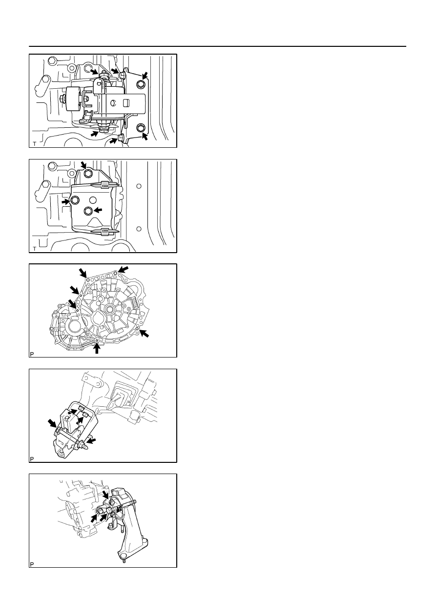
31.
REMOVE MANUAL TRANSAXLE ASSY
(a)
Remove the 6 bolts and transaxle from the engine.
32.
REMOVE TRANSVERSE ENGINE ENGINE
MOUNTING BRACKET
(a)
Remove the bolt, nut and engine mounting insulator FR
from the engine mounting bracket FR.
(b)
Remove the 2 bolts and engine mounting bracket FR from
the transaxle.
33.
REMOVE TRANSVERSE ENGINE ENGINE
MOUNTING BRACKET
(a)
Remove the bolt and engine mounting insulator RR from
the engine mounting bracket RR.
(b)
Remove the 3 bolts and engine mounting bracket RR
from the transaxle.
C70061
(a)
(a)
(b)
C70063
(a)
(b)
C70065
A
B
C
C
A
B
D26700
D26699
A
A
A
A
B
–
MANUAL TRANSMISSION/TRANSAXLE
MANUAL TRANSAXLE ASSY
41–21
1421
Author:
Date:
2004 COROLLA (RM1037U)
34.
INSTALL TRANSVERSE ENGINE ENGINE MOUNTING
BRACKET
(a)
Install the engine mounting bracket RR and 3 bolts to the
transaxle.
Torque: 64 N
⋅
m (653 kgf
⋅
cm, 47 ft
⋅
lbf)
(b)
Install the engine mounting insulator RR and bolt to the
engine mounting bracket RR.
Torque: 87 N
⋅
m (888 kgf
⋅
cm, 64 ft
⋅
lbf)
35.
INSTALL TRANSVERSE ENGINE ENGINE MOUNTING
BRACKET
(a)
Install the engine mounting bracket FR and 2 bolts to the
transaxle.
Torque: 64 N
⋅
m (653 kgf
⋅
cm, 47 ft
⋅
lbf)
(b)
Install the engine mounting insulator FR, bolt and nut to
the engine mounting bracket FR.
Torque: 52 N
⋅
m (530 kgf
⋅
cm, 38 ft
⋅
lbf)
36.
INSTALL MANUAL TRANSAXLE ASSY
(a)
Align the input shaft with the clutch disc and install the
transaxle to the engine.
(b)
Install the 6 bolts.
Torque:
Bolt A: 64 N
⋅
m (650 kgf
⋅
cm, 47 ft
⋅
lbf)
Bolt B: 47 N
⋅
m (480 kgf
⋅
cm, 35 ft
⋅
lbf)
Bolt C: 23 N
⋅
m (230 kgf
⋅
cm, 17 ft
⋅
lbf)
37.
INSTALL TRANSVERSE ENGINE ENGINE MOUNTING
BRACKET
(a)
Install the engine mounting bracket LH to the transaxle
with the 3 bolts.
Torque: 52 N
⋅
m (530 kgf
⋅
cm, 38 ft
⋅
lbf)
38.
INSTALL TRANSVERSE ENGINE ENGINE MOUNTING
INSULATOR
(a)
Install the engine mounting insulator LH with the 5 bolts
and nut.
Torque:
Bolt A: 52 N
⋅
m (530 kgf
⋅
cm, 38 ft
⋅
lbf)
Bolt B: 80 N
⋅
m (816 kgf
⋅
cm, 59 ft
⋅
lbf)
D11561
(a)
(a)
(b)
(c)
D26696
D26768
41–22
–
MANUAL TRANSMISSION/TRANSAXLE
MANUAL TRANSAXLE ASSY
1422
Author:
Date:
2004 COROLLA (RM1037U)
39.
INSTALL FRONT SUSPENSION CROSSMEMBER SUB–ASSY (See page
26–13
)
SST
09670–00010
40.
CONNECT STEERING INTERMEDIATE SHAFT (See page
51–18
)
41.
INSTALL COLUMN HOLE COVER SILENCER SHEET (See page
51–18
)
42.
CONNECT RETURN TUBE SUB–ASSY (See page
51–18
)
SST
09023–12700
43.
CONNECT PRESSURE FEED TUBE ASSY (See page
51–18
)
SST
09023–12700
44.
INSTALL FRONT DRIVE SHAFT ASSY LH (See page
30–6
)
45.
INSTALL FRONT DRIVE SHAFT ASSY RH
HINT:
Install the RH side by the same procedures as LH side.
46.
INSTALL STARTER ASSY
(a)
Install the starter assy and 2 bolts to the transaxle.
Torque: 37 N
⋅
m (378 kgf
⋅
cm, 27 ft
⋅
lbf)
(b)
Connect the starter connector.
(c)
Install the wire and nut to starter assy.
Torque: 9.8 N
⋅
m (100 kgf
⋅
cm, 87 in.
⋅
lbf)
47.
CONNECT FLOOR SHIFT CABLE TRANSMISSION
CONTROL SHIFT
(a)
Connect the shift cable end, and install the washer and
clip.
48.
CONNECT FLOOR SHIFT CABLE TRANSMISSION
CONTROL SELECT
(a)
Connect the select cable end, and install the washer and
clip.
D26730
A
B
C
A
B
D11552
D11558
F16859
A
B
F16860
–
MANUAL TRANSMISSION/TRANSAXLE
MANUAL TRANSAXLE ASSY
41–23
1423
Author:
Date:
2004 COROLLA (RM1037U)
49.
CONNECT CLUTCH RELEASE CYLINDER ASSY
(a)
Install the release cylinder with the 5 bolts.
Torque:
Bolt A: 25 N
⋅
m (250 kgf
⋅
cm, 19 ft
⋅
lbf)
Bolt B: 12 N
⋅
m (120 kgf
⋅
cm, 9 ft
⋅
lbf)
Bolt C: 5.0 N
⋅
m (51 kgf
⋅
cm, 44 in.
⋅
lbf)
50.
CONNECT CONNECTOR
(a)
Connect the back–up lamp switch connector.
(b)
w/o ABS:
Connect the speed sensor connector.
51.
CONNECT WIRE HARNESS
(a)
Install the 2 wire harness clamps to the transaxle with the
2 bolts.
Torque:
Bolt A: 25.5 N
⋅
m (260 kgf
⋅
cm, 19 ft
⋅
lbf)
Bolt B: 12.8 N
⋅
m (131 kgf
⋅
cm, 9 ft
⋅
lbf)
(1)
Connect the wire harness clamp.
(b)
Install the 2 bolts and 2 ground cables.
Torque: 13 N
⋅
m (133 kgf
⋅
cm, 10 ft
⋅
lbf)
C80159
41–24
–
MANUAL TRANSMISSION/TRANSAXLE
MANUAL TRANSAXLE ASSY
1424
Author:
Date:
2004 COROLLA (RM1037U)
52.
INSTALL CRUISE CONTROL ACTUATOR ASSY (W/ CRUISE CONTROL) (See page
82–4
)
53.
INSTALL BATTERY CARRIER
(a)
Install the battery carrier and 4 bolts.
Torque: 13 N
⋅
m (133 kgf
⋅
cm, 10 ft
⋅
lbf)
54.
INSTALL BATTERY TRAY
55.
INSTALL BATTERY
56.
INSTALL BATTERY CLAMP SUB–ASSY
Torque:
Bolt: 5.0 N
⋅
m (51 kgf
⋅
cm, 44 in.
⋅
lbf)
Nut: 3.5 N
⋅
m (36 kgf
⋅
cm, 31 in.
⋅
lbf)
57.
INSTALL AIR CLEANER ASSY
Torque: 7.0 N
⋅
m (71 kgf
⋅
cm, 62 in.
⋅
lbf)
58.
INSTALL CYLINDER HEAD COVER NO.2
Torque: 7.0 N
⋅
m (71 kgf
⋅
cm, 62 in.
⋅
lbf)
59.
INSTALL HOOD SUB–ASSY
Torque: 13 N
⋅
m (133 kgf
⋅
cm, 10 ft
⋅
lbf)
60.
INSPECT HOOD SUB–ASSY
61.
ADJUST HOOD SUB–ASSY (See page
75–1
)
62.
ADD TRANSAXLE OIL (See page
41–2
)
63.
INSPECT TRANSAXLE OIL (See page
41–2
)
64.
BLEED POWER STEERING FLUID (See page
51–3
)
65.
INSTALL FRONT WHEELS
Torque: 103 N
⋅
m (1,050 kgf
⋅
cm, 76 ft
⋅
lbf)
66.
PLACE FRONT WHEELS FACING STRAIGHT AHEAD
67.
INSTALL EXHAUST PIPE (See page
15–2
)
68.
INSTALL ENGINE UNDER COVER LH
69.
INSTALL ENGINE UNDER COVER RH
70.
INSPECT FRONT WHEEL ALIGNMENT (See page
26–5
)
71.
CHECK ABS SPEED SENSOR SIGNAL (See page
05–297
)
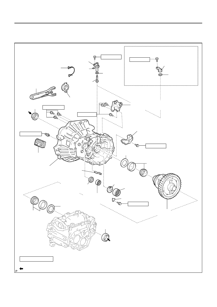
4107E–01
C95305
Speedometer Sensor
N
⋅
m (kgf
⋅
cm, ft
⋅
lbf)
: Specified torque
Non–reusable part
Apply MP grease
Transmission Case Oil Seal
w/ ABS:
Speedometer Driven
Hole Cover Sub–assy
O–Ring
w/o ABS:
Clip
Speedometer
Driven (MTM)
Gear Sub–assy
Clutch Release
Bearing Clip
Clutch Release
Fork Sub–assy
Release
Fork Support
Transaxle Case
Oil Seal
Clutch Release
Fork Boot
Front Transaxle
Case Oil Seal
Output Shaft
(MTM) Cover
Output Shaft
Front Bearing
Input Shaft
Front Bearing
Shim
FR Differential
Case Rear Tapered
Roller Bearing
Bearing Lock Plate
Shim
FR Differential Case Front
Tapered Roller Bearing
O–Ring
Transmission
Magnet
Clutch Release
Bearing Assy
Floor Shift Control
Lever Housing Support Bracket
Manual Transaxle
Case Receiver
11.3 (115, 8)
11.3 (115, 8)
29.4 (300, 22)
11.3 (115, 8)
11.3 (115, 8)
11.3 (115, 8)
36.8 (375, 25)
Transaxle Case
Differential Case Assy
–
MANUAL TRANSMISSION/TRANSAXLE
MANUAL TRANSAXLE ASSY (C59)
41–25
1425
Author:
Date:
2004 COROLLA (RM1037U)
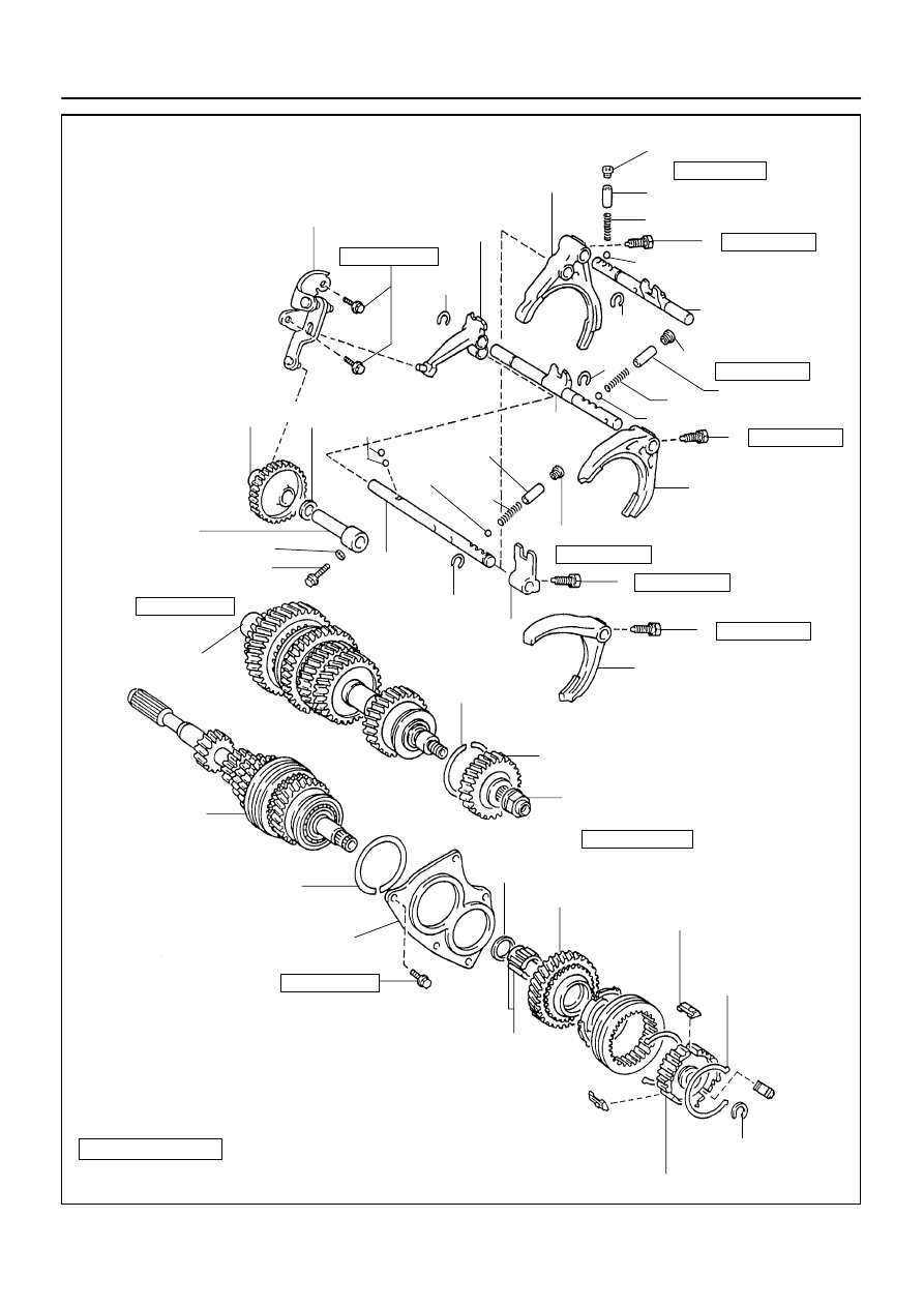
MANUAL TRANSAXLE ASSY (C59)
COMPONENTS
Z18280
Shift Detent Ball Plug
Gear Shift Fork No.1
Seat
Spring
Gear Shift Fork Shaft
Sub–assy No.1
Snap Ring
Reverse
Shift Fork
Thrust Washer
Reverse Idler
Gear Sub–assy
Reverse Idler
Gear Shaft
Gasket
Output Shaft Assy
Seat
Spring
Gear Shift Fork No.3
Gear Shift Head No.1
Gear Shift Fork No.2
Output Shaft
Rear Bearing Hole
Snap Ring
5th Driven Gear
Manual Transmission
Output Shaft Rear Set Nut
5th Gear Bearing Spacer
5th Gear
Synchromesh Shifting Key
Input Shaft Assy
Input Shaft Rear
Bearing Hole Snap Ring
Bearing Retainer Rear (MTM)
5th Gear Needle Roller Bearing
Input Shaft Snap Ring
Transmission Clutch Hub No.3
N
⋅
m (kgf
⋅
cm, ft
⋅
lbf)
: Specified torque
Non–reusable part
Precoated part
Synchromesh Shifting
Key Spring
Ball
Snap Ring
Snap
Ring
Gear Shift
Fork Shaft No.2
Snap Ring
Reverse Idler Gear
Shaft Bolt
Reverse Shift Arm
Bracket Assy
24.5 (250, 18)
15.7 (160, 12)
15.7 (160, 12)
Shift Detent Ball Plug
24.5 (250, 18)
Shift Detent Ball Plug
24.5 (250, 18)
15.7 (160, 12)
29.4 (300, 22)
15.7 (160, 12)
x5
117.6 (1,200, 87)
Gear Shift
Fork Shaft No.3
27.4 (279, 20)
17.2 (175, 13)
Spring
Seat
Shift Detent Ball
Shift
Detent
Ball
Shift Detent Ball
41–26
–
MANUAL TRANSMISSION/TRANSAXLE
MANUAL TRANSAXLE ASSY (C59)
1426
Author:
Date:
2004 COROLLA (RM1037U)
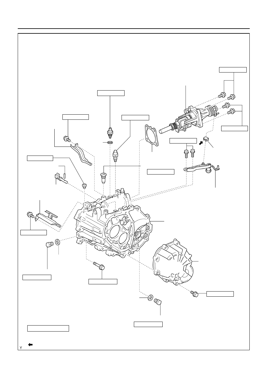
D12108
Gasket
N
⋅
m (kgf
⋅
cm, ft
⋅
lbf)
: Specified torque
Non–reusable part
Precoated part
39.2 (400, 29)
Shift & Select Lever Shaft Assy
Back Up Lamp Switch
Lock Ball Assy No.1
Reverse Restrict Pin Plug
Oil Receiver Pipe No.2
(MTM)
Reverse
Restrict Pin Assy
Lock Ball Assy No.1
Control Shift
Lever Bush
Selecting Bellcrank Assy
Manual Transmission Case
Oil Receiver Pipe No. 1 (MTM)
Slotted Pin
Manual Transmission
Case Cover Sub–assy
Drain (MTM) Plug Sub–assy
Manual Transmission Filler Plug
Apply MP grease
x13
x9
Gasket
Gasket
39.2 (400, 29)
39.2 (400, 29)
17.2 (175, 13)
Gasket
40.2 (410, 30)
29.4 (300, 22)
19.6 (200, 14)
19.6 (200, 14)
24.5 (250, 18)
29.4 (300, 22)
12.7 (130, 9)
18.1 (185, 14)
17.2 (175, 13)
–
MANUAL TRANSMISSION/TRANSAXLE
MANUAL TRANSAXLE ASSY (C59)
41–27
1427
Author:
Date:
2004 COROLLA (RM1037U)
4107F–01
C80549
C80550
C67601
41–28
–
MANUAL TRANSMISSION/TRANSAXLE
MANUAL TRANSAXLE ASSY (C59)
1428
Author:
Date:
2004 COROLLA (RM1037U)
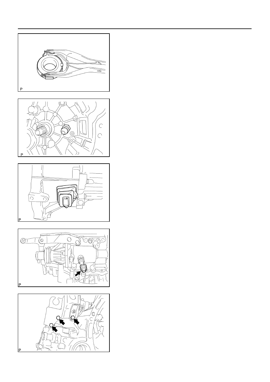
OVERHAUL
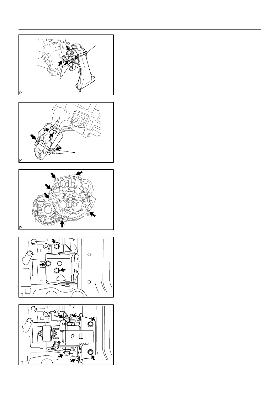
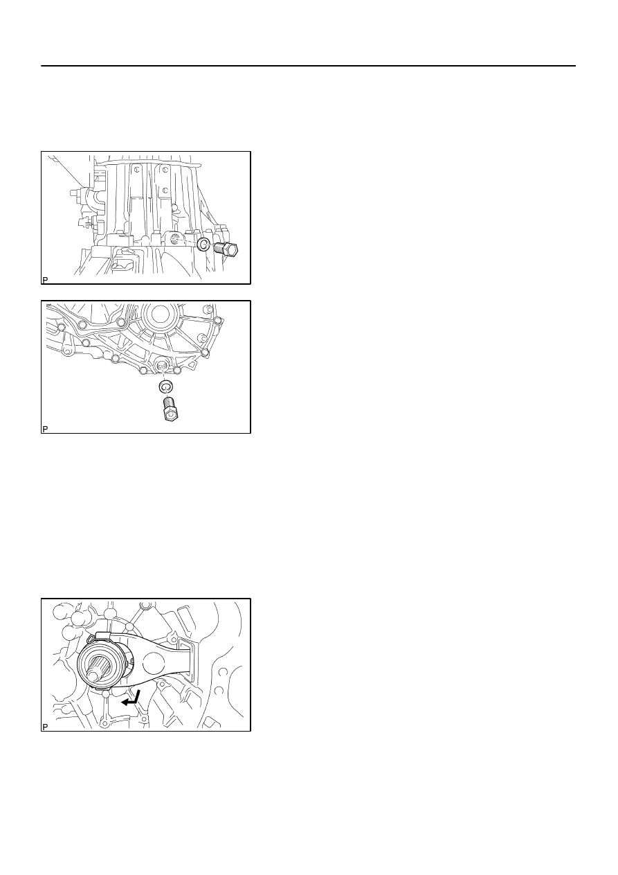
1.
REMOVE MANUAL TRANSMISSION FILLER PLUG
(a)
Remove the manual transmission filler plug and gasket
from the manual transmission case.
2.
REMOVE DRAIN (MTM) PLUG SUB–ASSY
(a)
Remove the drain (MTM) plug sub–assy and gasket from
the manual transmission case.
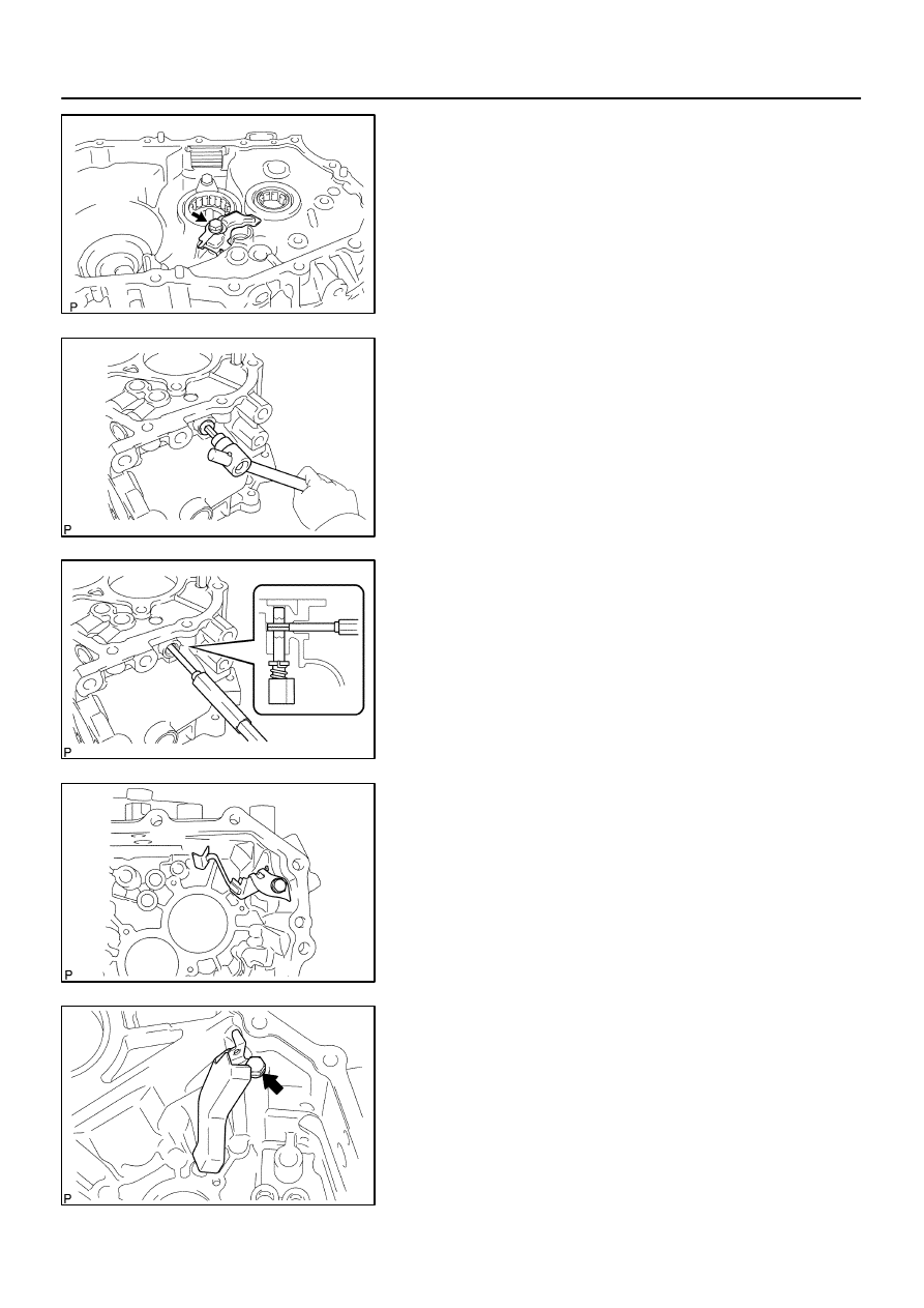
3.
REMOVE SPEEDOMETER SENSOR (W/O ABS)
(a)
Remove the bolt and speedometer sensor from the transaxle case.
(b)
Remove the O–ring from the speedometer sensor.
4.
REMOVE SPEEDOMETER DRIVEN (MTM) GEAR SUB–ASSY (W/O ABS)
(a)
Remove the clip and speedometer driven (MTM) gear sub–assy from the speedometer sensor.
5.
REMOVE SPEEDOMETER DRIVEN HOLE COVER SUB–ASSY (W/ ABS)
(a)
Remove the bolt and speedometer driven hole cover sub–assy from the transaxle case.
(b)
Remove the O–ring from the speedometer driven hole cover.
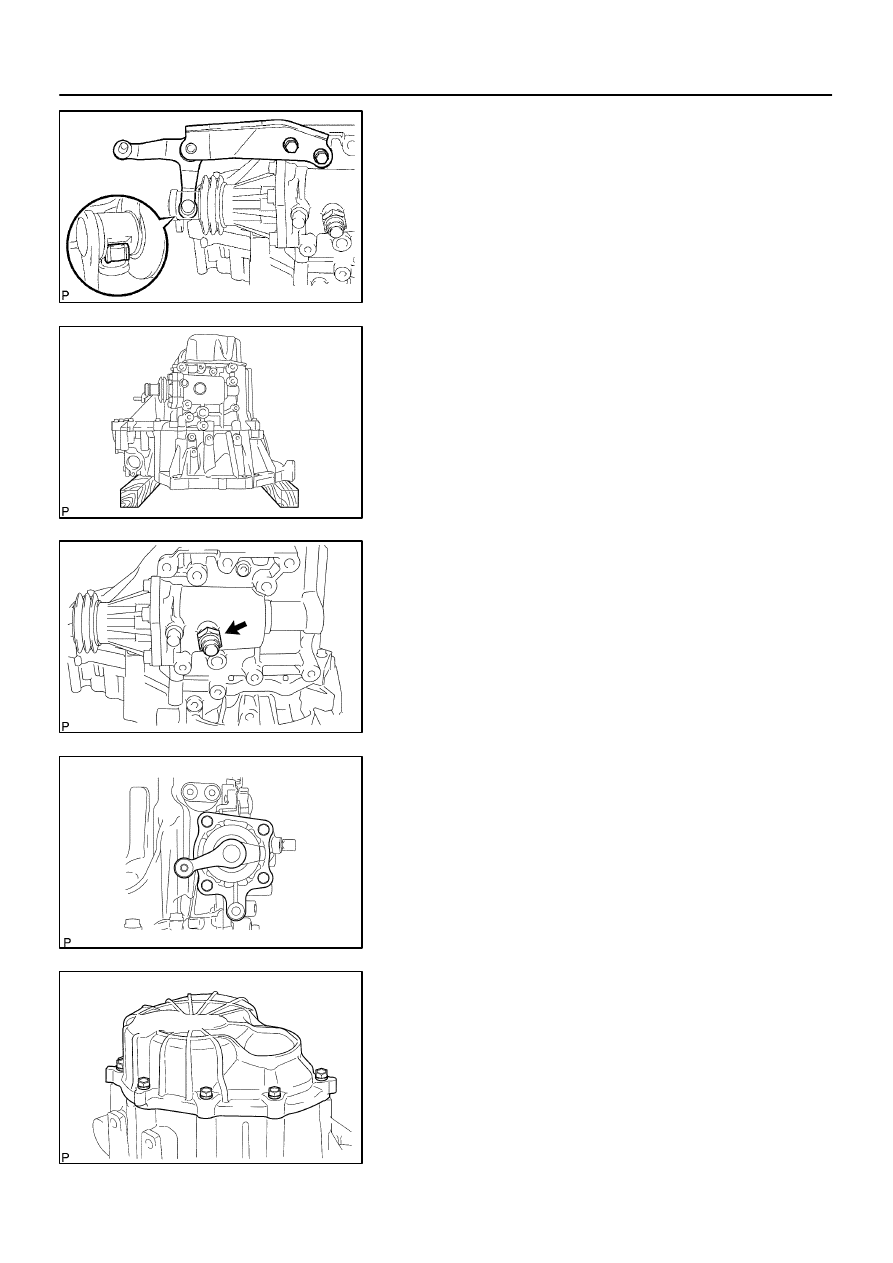
6.
REMOVE CLUTCH RELEASE FORK SUB–ASSY
(a)
Remove the clutch release fork sub–assy with clutch re-
lease bearing assy from the transaxle case.
C67602
C67604
C80331
C95184
C80333
–
MANUAL TRANSMISSION/TRANSAXLE
MANUAL TRANSAXLE ASSY (C59)
41–29
1429
Author:
Date:
2004 COROLLA (RM1037U)
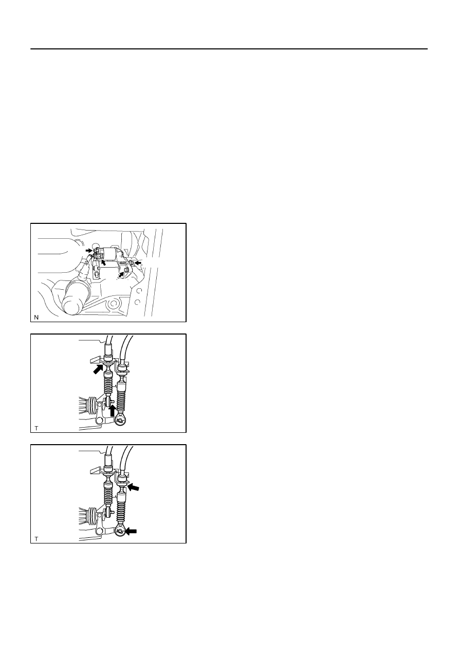
7.
REMOVE CLUTCH RELEASE BEARING ASSY
(a)
Remove the clutch release bearing clip and clutch release
bearing assy from the clutch release fork sub–assy.
8.
REMOVE RELEASE FORK SUPPORT
(a)
Remove the clutch release fork support from the trans-
axle case.
9.
REMOVE CLUTCH RELEASE FORK BOOT
(a)
Remove the clutch release fork boot from the transaxle
case.
10.
REMOVE BACK UP LAMP SWITCH ASSY
(a)
Remove the back up lamp switch assy and gasket from
the manual transmission case.
11.
REMOVE FLOOR SHIFT CONTROL LEVER HOUSING
SUPPORT BRACKET
(a)
Remove the 3 bolts and floor shift control lever housing
support bracket from the transaxle case.
C95185
C80336
C95186
C95187
C95188
41–30
–
MANUAL TRANSMISSION/TRANSAXLE
MANUAL TRANSAXLE ASSY (C59)
1430
Author:
Date:
2004 COROLLA (RM1037U)
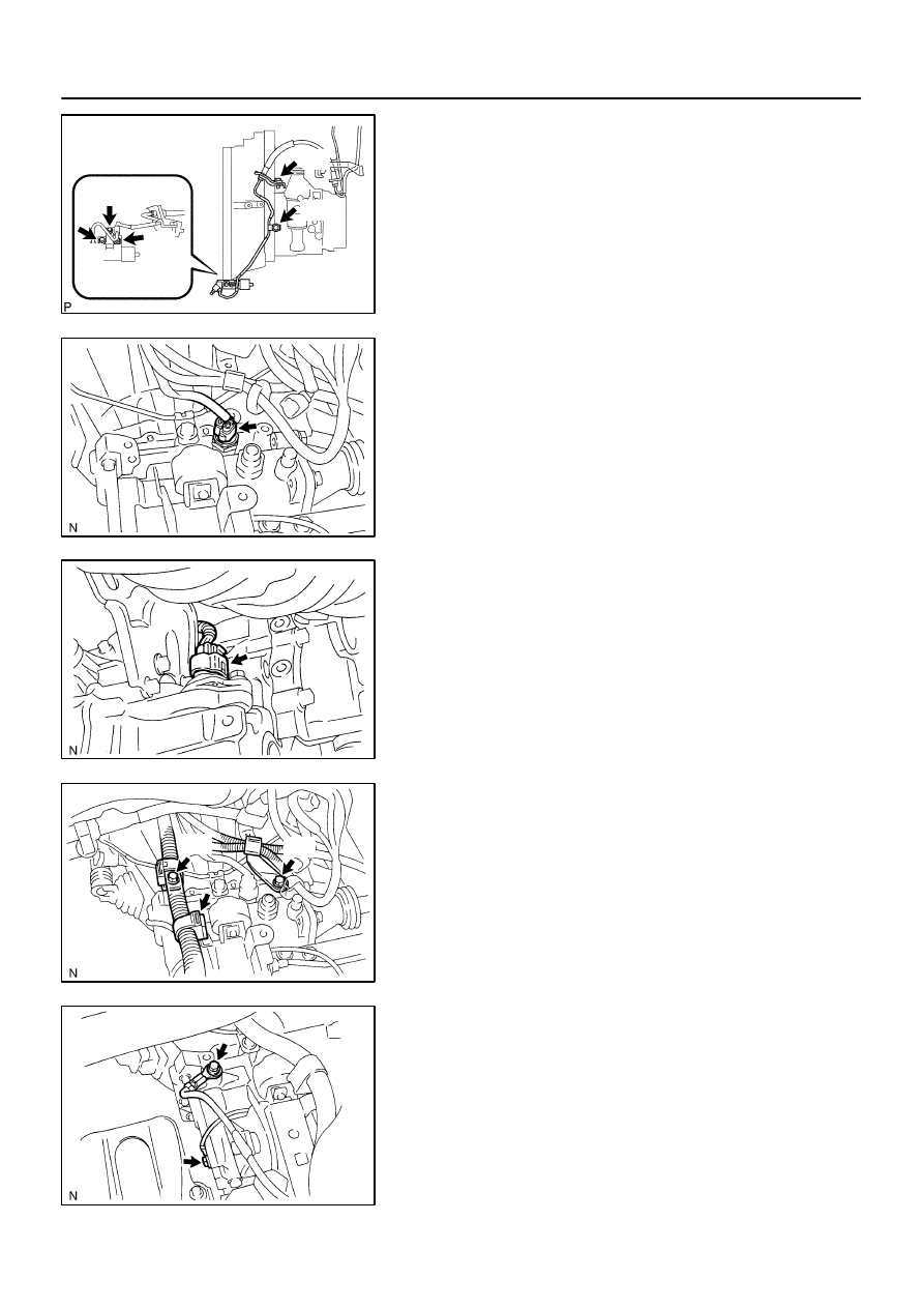
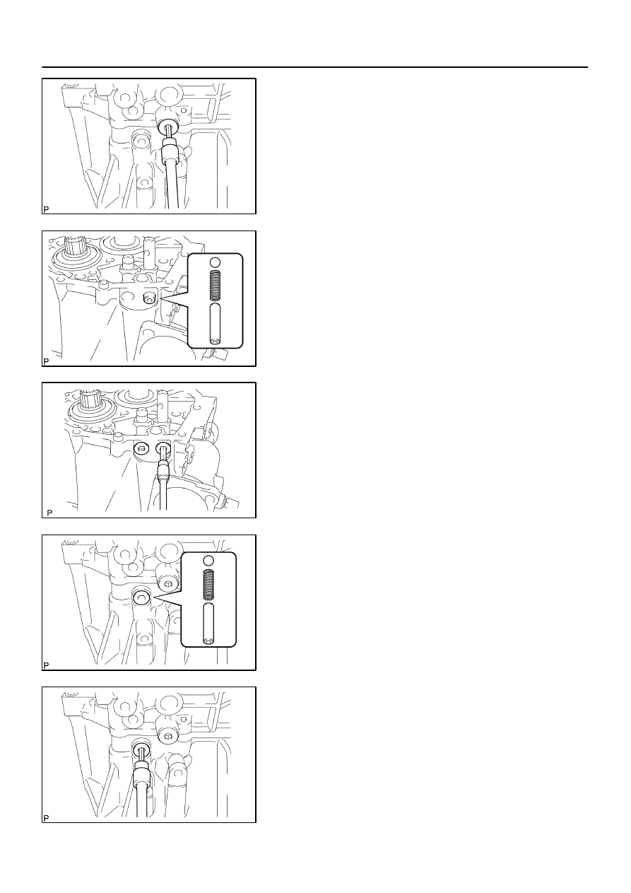
12.
REMOVE SELECTING BELL CRANK ASSY
(a)
Remove the 2 bolts and selecting bellcrank assy from the
manual transmission case.
(b)
Remove the control shift lever bush.
13.
FIX MANUAL TRANSAXLE ASSY
(a)
Using 2 wooden blocks, fix the manual transaxle assy.
14.
REMOVE LOCK BALL ASSY NO.1
(a)
Remove the lock ball assy No.1 from the manual trans-
mission case.
15.
REMOVE SHIFT & SELECT LEVER SHAFT ASSY
(a)
Remove the 4 bolts, shift & select lever shaft assy and
gasket from the manual transmission case.
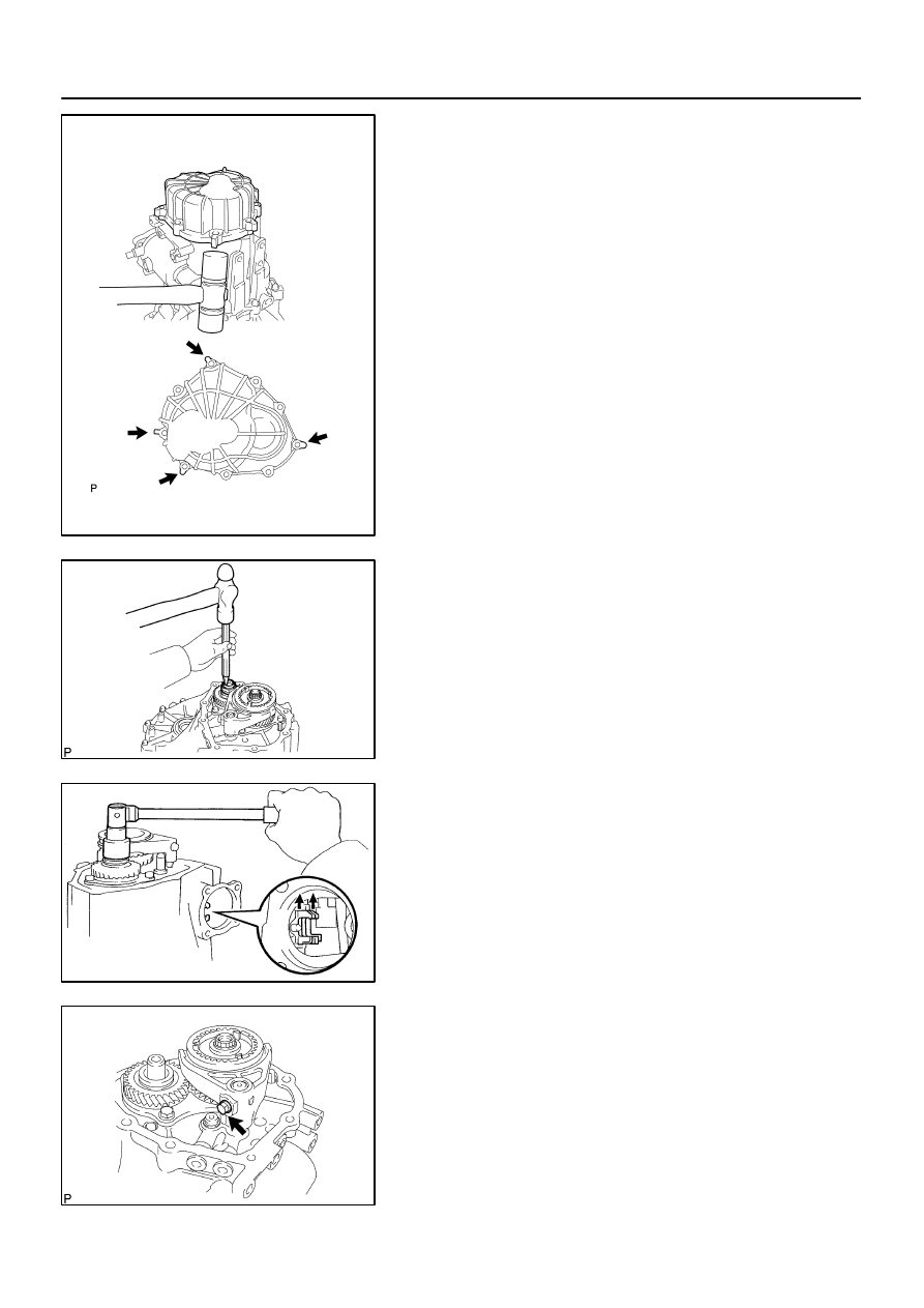
16.
REMOVE MANUAL TRANSMISSION CASE COVER
SUB–ASSY
(a)
Remove the 9 bolts.
C95189
C80341
Q06512
C80342
–
MANUAL TRANSMISSION/TRANSAXLE
MANUAL TRANSAXLE ASSY (C59)
41–31
1431
Author:
Date:
2004 COROLLA (RM1037U)
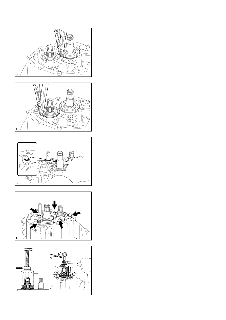
(b)
Using a plastic hammer, carefully tap the projection of the
manual transmission case cover sub–assy to remove it
from the manual transmission case.
NOTICE:
Do not damage the manual transmission case.
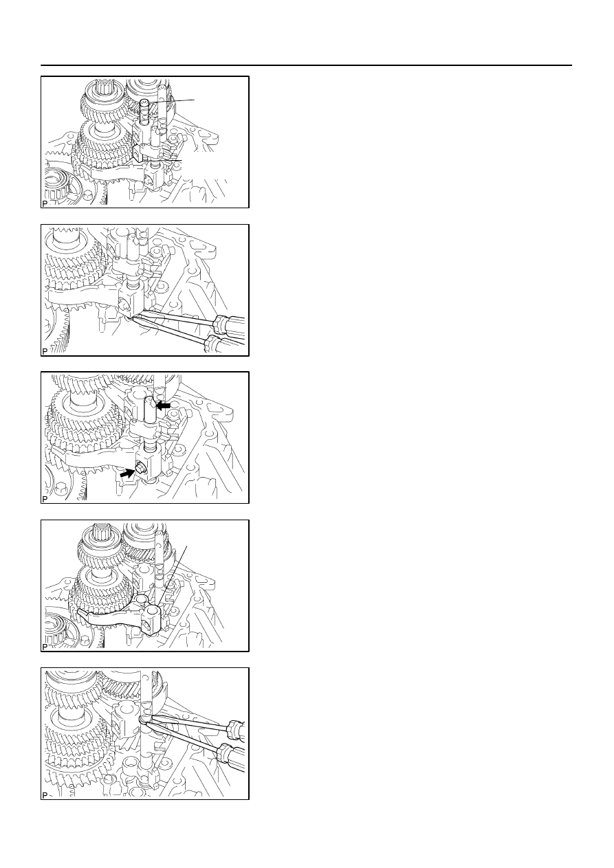
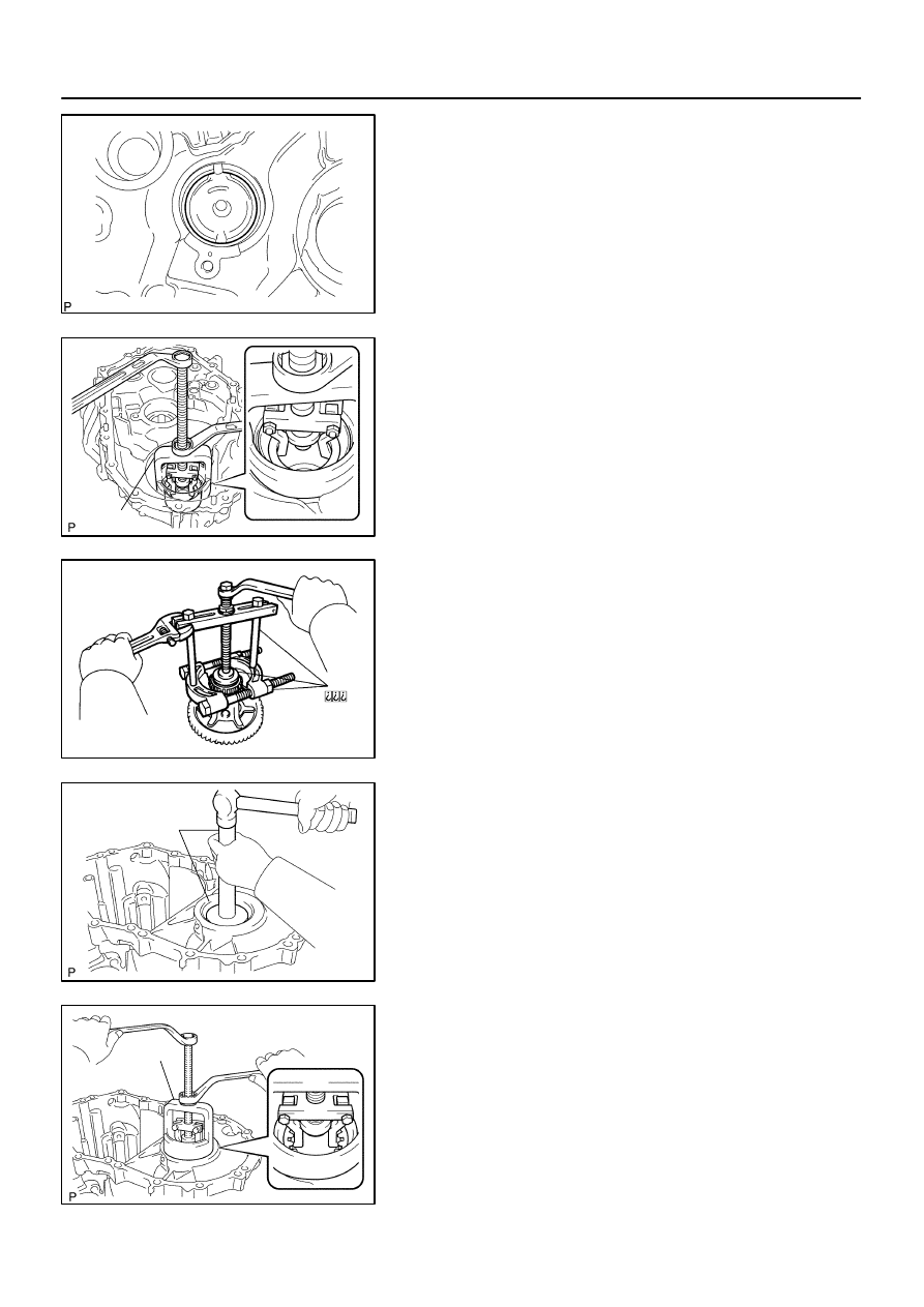
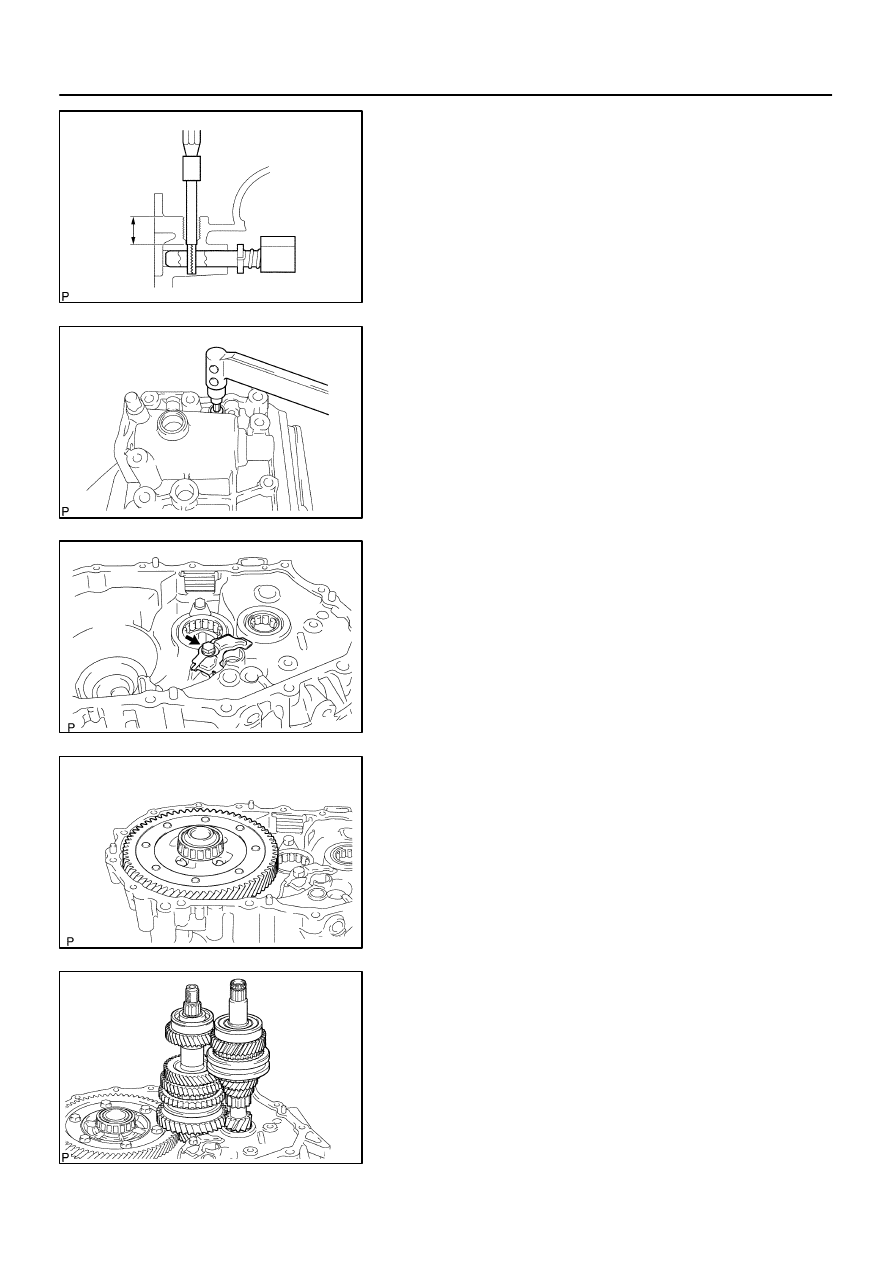
17.
REMOVE MANUAL TRANSMISSION OUTPUT SHAFT
REAR SET NUT
(a)
Using a chisel and a hammer, loosen the staked part of
the manual transmission output shaft rear set nut.
(b)
Engage the gear to the double meshing.
(c)
Remove the manual transmission output shaft rear set
nut.
(d)
Disengage the double mashing of the gear.
18.
REMOVE GEAR SHIFT FORK NO.3
(a)
Remove the gear shift fork lock bolt from the gear shift fork
No.3.
C80343
C80344
C80345
C80346
41–32
–
MANUAL TRANSMISSION/TRANSAXLE
MANUAL TRANSAXLE ASSY (C59)
1432
Author:
Date:
2004 COROLLA (RM1037U)
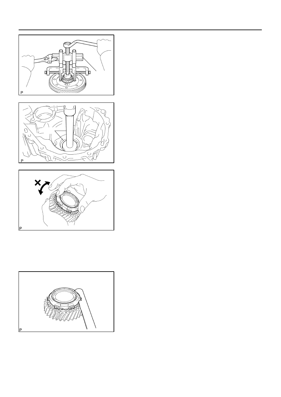
(b)
Remove the transmission hub sleeve No.3 with gear shift
fork No.3 from the transmission clutch hub No.3.
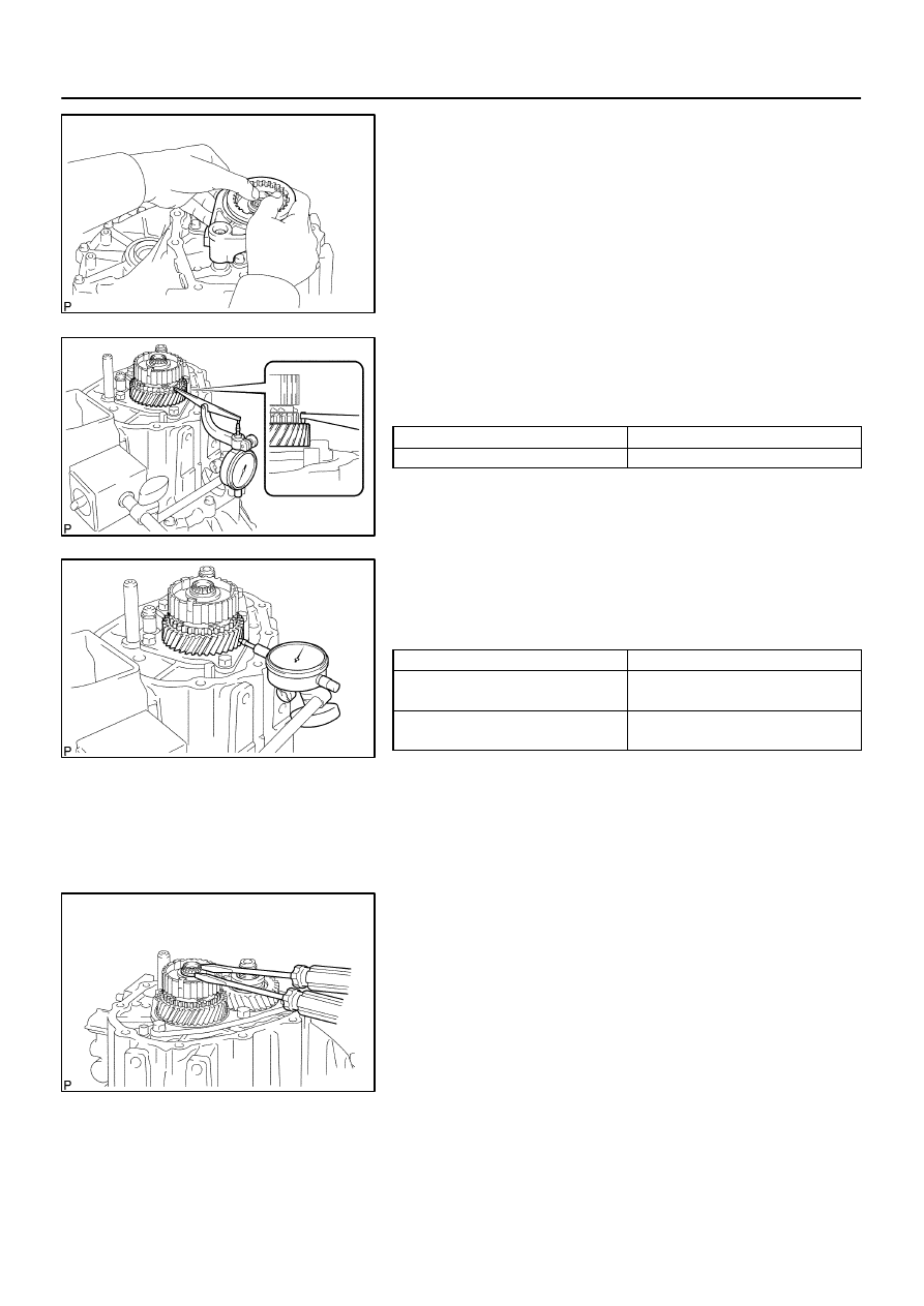
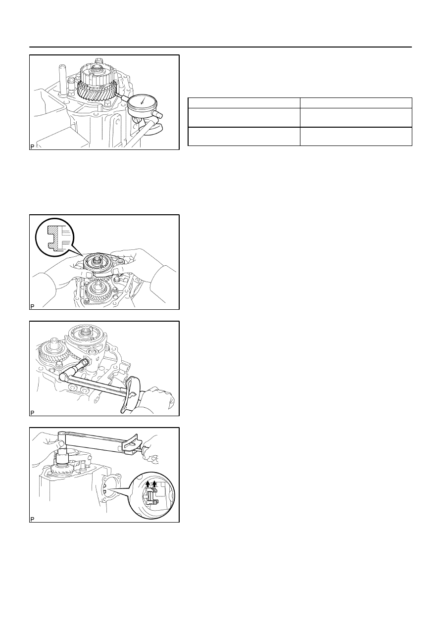
19.
INSPECT 5TH GEAR THRUST CLEARANCE
(a)
Using a dial indicator, measure the 5th gear thrust clear-
ance.
5th gear thrust clearance:
Standard clearance: mm (in.)
Maximum clearance: mm (in.)
0.10 – 0.57 (0.0039 – 0.0224)
0.57 (0.0224)
20.
INSPECT 5TH GEAR RADIAL CLEARANCE
(a)
Using a dial indicator, measure the 5th gear radial clear-
ance.
5th gear radial clearance: mm (in.)
Standard clearance: mm (in.)
Maximum clearance: mm (in.)
KOYO made:
0.015 – 0.058 (0.0006 – 0.0023)
KOYO made: 0.058 ( 0.0023)
NSK made:
0.015 – 0.056 (0.0006 – 0.0022)
NSK made: 0.056 (0.0022)
If the clearance exceeds the maximum, replace the gear,
needle roller bearing or shaft.
21.
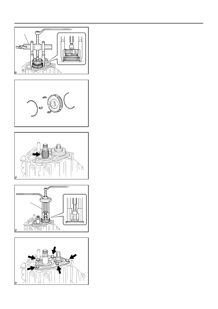
REMOVE TRANSMISSION CLUTCH HUB NO.3
(a)
Using 2 screwdrivers and a hammer, tap out the snap
ring.
HINT:
Using a waste to prevent the snap ring from being scattered.
C80347
SST
D07737
C80348
C80349
SST
C80350
–
MANUAL TRANSMISSION/TRANSAXLE
MANUAL TRANSAXLE ASSY (C59)
41–33
1433
Author:
Date:
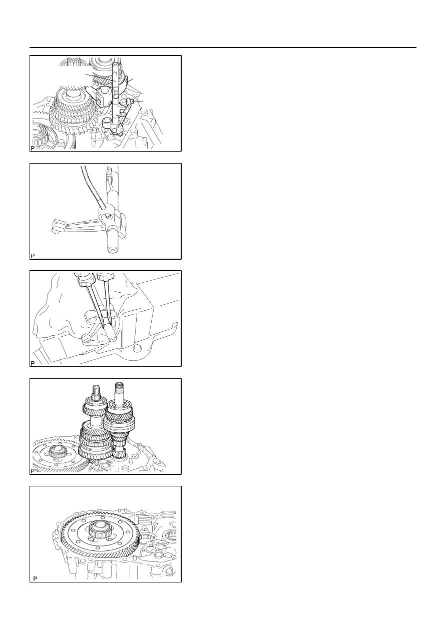
2004 COROLLA (RM1037U)
(b)
Using SST, remove the transmission clutch hub No.3, 5th
gear and synchronizer ring No.3 from the input shaft.
SST
09950–40011 (09951–04020, 09952–04010,
09953–04030, 09954–04010, 09955–04071,
09957–04010), 09950–60010 (09951–00200)
(c)
Remove the 3 synchromesh shifting keys and 2 synchro-
mesh shifting key springs from the transmission clutch
hub No.3.
22.
REMOVE 5TH GEAR NEEDLE ROLLER BEARING
(a)
Remove the 5th gear needle roller bearing and 5th gear
bearing spacer from the input shaft.
23.
REMOVE 5TH DRIVEN GEAR
(a)
Using SST, remove the 5th driven gear from the output
shaft.
SST
09950–30012 (09951–03010, 09953–03010,
09954–03010, 09955–03011, 09957–04010),
09950–60010 (09951–00190)
24.
REMOVE BEARING RETAINER REAR (MTM)
(a)
Remove the 5 bolts and bearing retainer rear (MTM) from
the manual transmission case.
C80351
C80352
C67639
C80353
C67634
41–34
–
MANUAL TRANSMISSION/TRANSAXLE
MANUAL TRANSAXLE ASSY (C59)
1434
Author:
Date:
2004 COROLLA (RM1037U)
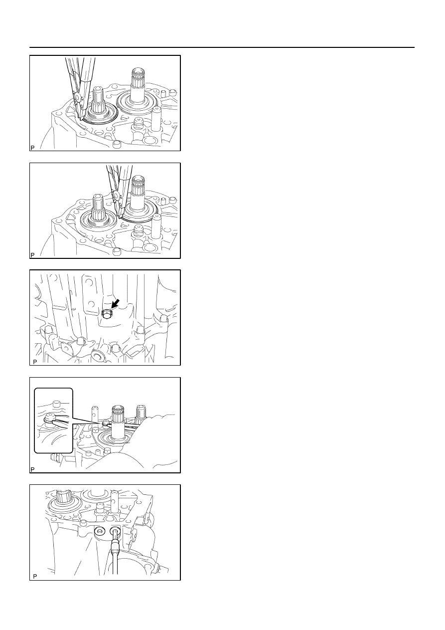
25.
REMOVE OUTPUT SHAFT REAR BEARING HOLE
SNAP RING
(a)
Using a snap ring expander, remove the output shaft rear
bearing hole snap ring from the output shaft.
26.
REMOVE INPUT SHAFT REAR BEARING HOLE SNAP
RING
(a)
Using a snap ring expander, remove the input shaft rear
bearing hole snap ring from the input shaft.
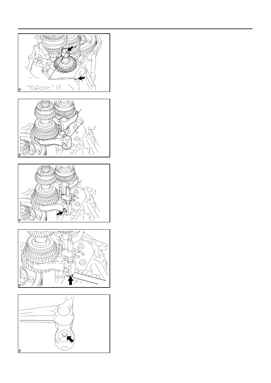
27.
REMOVE REVERSE IDLER GEAR SHAFT BOLT
(a)
Remove the reverse idler gear shaft bolt and gasket from
the manual transmission case.
28.
REMOVE SHIFT FORK SHAFT SHAFT SNAP RING
(a)
Using 2 screwdrivers and a hammer, tap out the snap ring
from the gear shift fork shaft No.2.
HINT:
Using a waste to prevent the snap ring from being scattered.
29.
REMOVE SHIFT DETENT BALL
(a)
Using a hexagon wrench, remove the 2 shift detent ball
plugs from the manual transmission case.
C67635
C80354
C80355
C80356
C80357
–
MANUAL TRANSMISSION/TRANSAXLE
MANUAL TRANSAXLE ASSY (C59)
41–35
1435
Author:
Date:
2004 COROLLA (RM1037U)
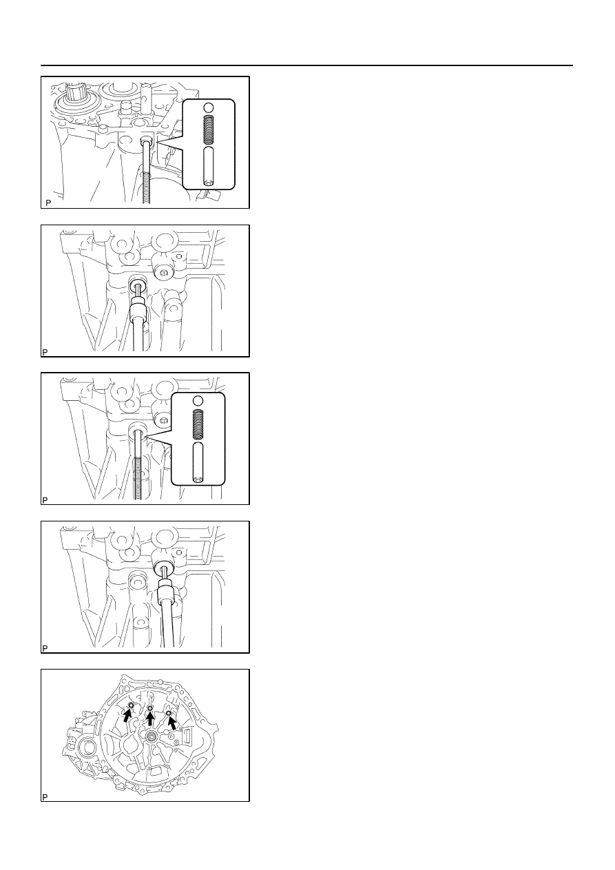
(b)
Using a magnetic finger, remove the 2 seats, 2 springs
and 2 shift detent balls from the manual transmission
case.
(c)
Using a hexagon wrench, remove the shift detent ball
plug from the transaxle case.
(d)
Using a magnetic finger, remove the seat, spring and shift
detent ball from the transaxle case.
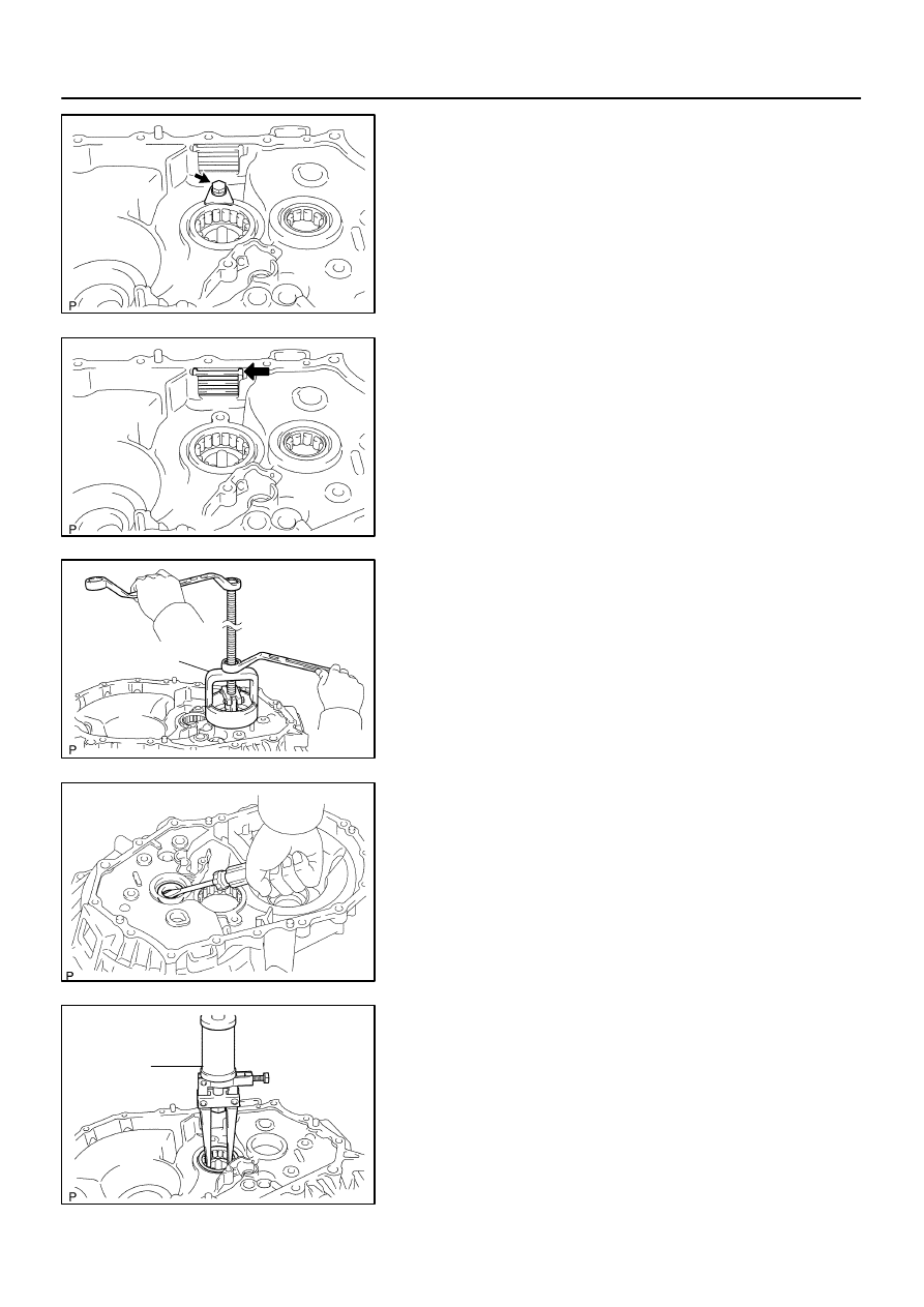
30.
REMOVE LOCK BALL ASSY NO.1
(a)
Using a hexagon wench, remove the lock ball assy No.1
from the manual transmission case.
31.
REMOVE MANUAL TRANSMISSION CASE
(a)
Remove the 3 bolts from the transaxle case side.
C80358
C67642
C80359
C80360
C80361
41–36
–
MANUAL TRANSMISSION/TRANSAXLE
MANUAL TRANSAXLE ASSY (C59)
1436
Author:
Date:
2004 COROLLA (RM1037U)
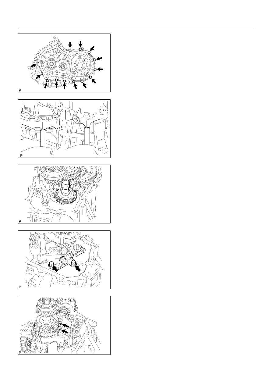
(b)
Remove the 13 bolts from the manual transmission case
side.
(c)
Using a brass bar and a hammer, carefully tap the projec-
tion of the manual transmission case to remove it from the
transaxle case.
NOTICE:
Do not damage the manual transmission case and trans-
axle case.
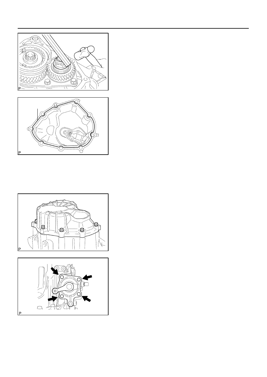
32.
REMOVE REVERSE IDLER GEAR SUB–ASSY
(a)
Remove the reverse idler gear sub–assy, thrust washer
and reverse idler gear shaft from the transaxle case.
33.
REMOVE REVERSE SHIFT ARM BRACKET ASSY
(a)
Remove the 2 bolts and reverse shift arm bracket assy
from the transaxle case.
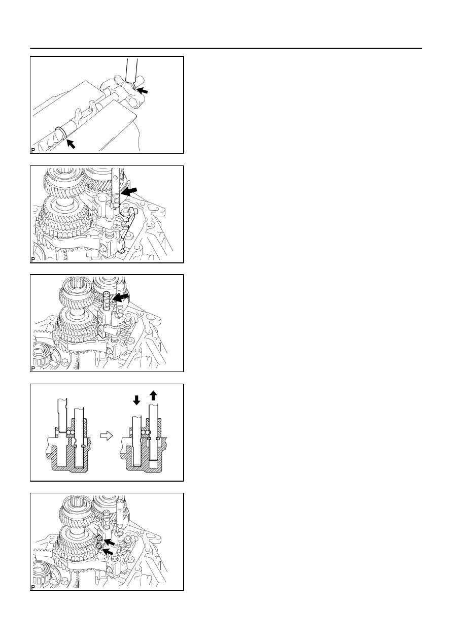
34.
REMOVE GEAR SHIFT FORK SHAFT NO.2
(a)
Remove the 2 bolts from the gear shift fork No. 2 and gear
shift head No.1.
C80362
Gear Shift
Fork Shaft
No.2
Gear Shift
Head No.1
C80363
C80364
C80365
Gear Shift
Fork No.1
C80366
–
MANUAL TRANSMISSION/TRANSAXLE
MANUAL TRANSAXLE ASSY (C59)
41–37
1437
Author:
Date:
2004 COROLLA (RM1037U)
(b)
Remove the gear shift fork shaft No.2 and gear shift head
No.1 from the transaxle case.
35.
REMOVE GEAR SHIFT FORK SHAFT SUB–ASSY
NO.1
(a)
Using 2 screwdrivers and a hammer, tap out the snap
rings.
HINT:
Using a waste to prevent the snap ring from being scattered.
(b)
Remove the gear shift fork lock bolt and gear shift fork
shaft sub–assy No.1 from the gear shift fork No.1.
(c)
Remove the gear shift fork No.1.
36.
REMOVE GEAR SHIFT FORK SHAFT NO.3
(a)
Using 2 screwdrivers and a hammer, tap out the snap ring
from the gear shift fork shaft No.3.
HINT:
Using a waste to prevent the snap ring from being scattered.
C80367
Gear Shift
Fork No.2
Reverse
Shift Fork
Gear Shift
Fork Shaft No.3
C80368
C80369
C80586
C67656
41–38
–
MANUAL TRANSMISSION/TRANSAXLE
MANUAL TRANSAXLE ASSY (C59)
1438
Author:
Date:
2004 COROLLA (RM1037U)
(b)
Remove the shift fork shaft No.3 with reverse shift fork
and gear shift fork No.2 from the transaxle case.
(c)
Using a magnetic finger, remove the 2 balls from the re-
verse shift fork.
(d)
Using 2 screwdrivers and a hammer, tap out the snap
ring.
HINT:
Using a waste to prevent the snap ring from being scattered.
(e)
Remove the reverse shift fork from the gear shift fork shaft
No.3.
37.
REMOVE INPUT SHAFT ASSY
(a)
Remove the input and output shaft assy from the trans-
axle case.
38.
REMOVE DIFFERENTIAL CASE ASSY
(a)
Remove the differential case assy from the transaxle
case.
C67657
C80372
C80373
C67644
C80374
–
MANUAL TRANSMISSION/TRANSAXLE
MANUAL TRANSAXLE ASSY (C59)
41–39
1439
Author:
Date:
2004 COROLLA (RM1037U)
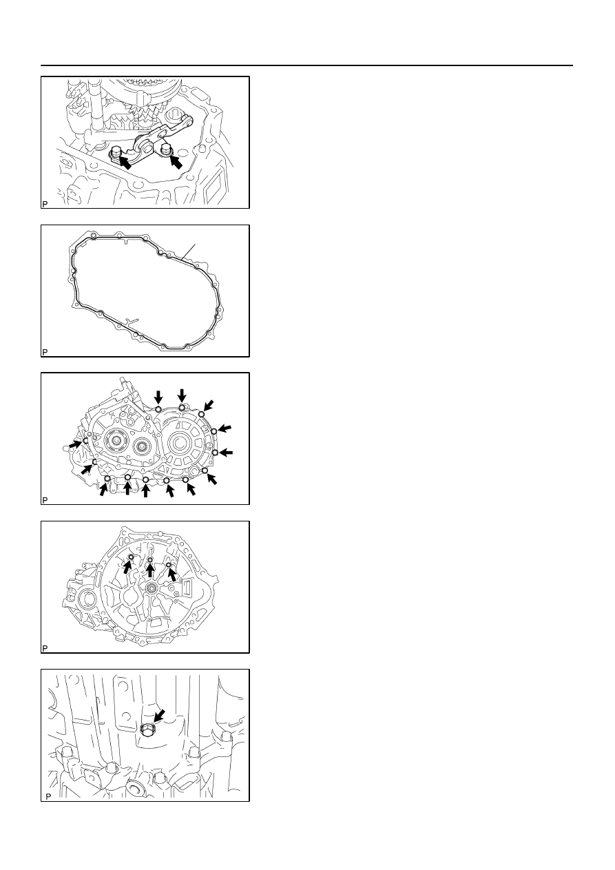
39.
REMOVE MANUAL TRANSAXLE CASE RECEIVER
(a)
Remove the bolt and manual transaxle case receiver from
the transaxle case.
40.
REMOVE REVERSE RESTRICT PIN ASSY
(a)
Using a hexagon wrench, remove the reverse restrict pin
plug from the manual transmission case.
(b)
Using a pin punch (
φ
5 mm) and a hammer, drive out the
slotted spring pin and remove the reverse restrict pin assy
from the manual transmission case.
41.
REMOVE OIL RECEIVER PIPE NO.1 (MTM)
(a)
Remove the bolt and oil receiver pipe No.1 (MTM) from
the manual transmission case.
NOTICE:
Be careful not to damage the oil receiver pipe No.1 (MTM).
42.
REMOVE OIL RECEIVER PIPE NO.2 (MTM)
(a)
Remove the bolt and oil receiver pipe No.2 (MTM) from
the manual transmission case.
NOTICE:
Be careful not to damage the oil receiver pipe No.2 (MTM).
C67658
C67659
C81783
SST
C95411
C82141
SST
41–40
–
MANUAL TRANSMISSION/TRANSAXLE
MANUAL TRANSAXLE ASSY (C59)
1440
Author:
Date:
2004 COROLLA (RM1037U)
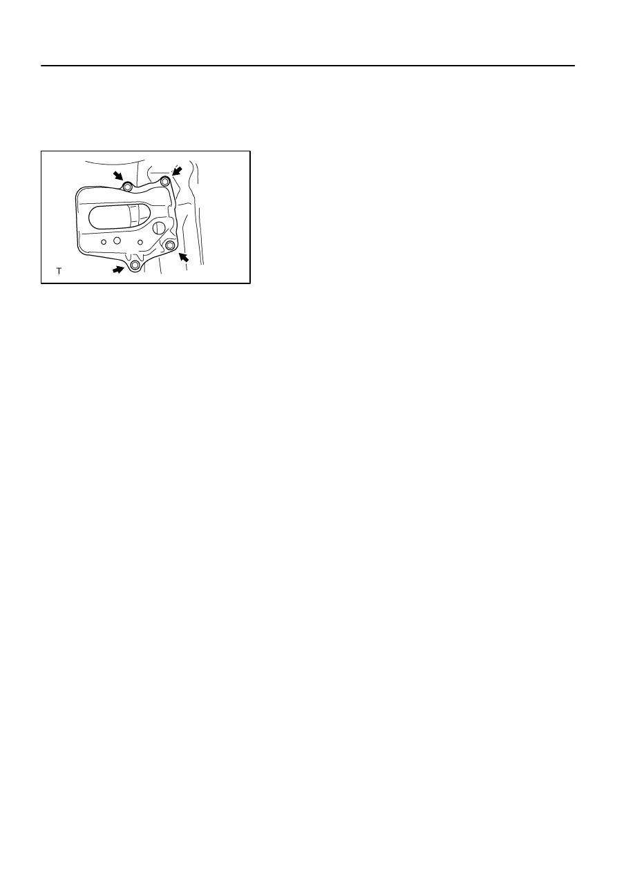
43.
REMOVE BEARING LOCK PLATE
(a)
Remove the bolt and bearing lock plate from the transaxle
case.
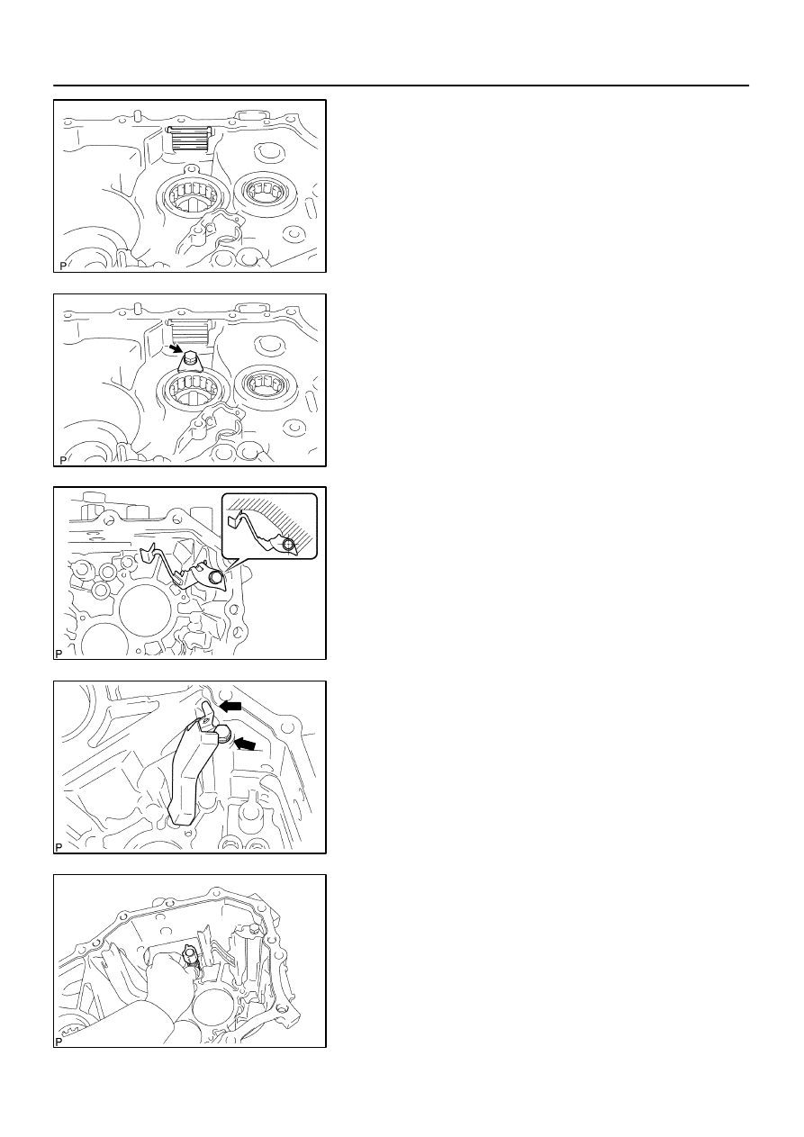
44.
REMOVE TRANSMISSION MAGNET
(a)
Remove the transmission magnet from the transaxle
case.
45.
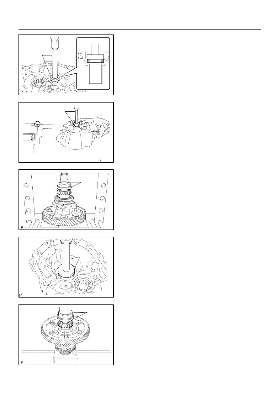
REMOVE INPUT SHAFT FRONT BEARING
(a)
Using SST, remove the input shaft front bearing from the
transaxle case.
SST
09612–65014 (09612–01050, 09612–01060)
46.
REMOVE FRONT TRANSAXLE CASE OIL SEAL
(a)
Using a screwdriver, remove the front transaxle case oil
seal from the transaxle case.
47.
REMOVE OUTPUT SHAFT FRONT BEARING
(a)
Using SST, remove the output shaft front bearing from the
transaxle case.
SST
09308–00010
C67719
C81785
SST
Z16129
C81789
SST
C81788
SST
–
MANUAL TRANSMISSION/TRANSAXLE
MANUAL TRANSAXLE ASSY (C59)
41–41
1441
Author:
Date:
2004 COROLLA (RM1037U)
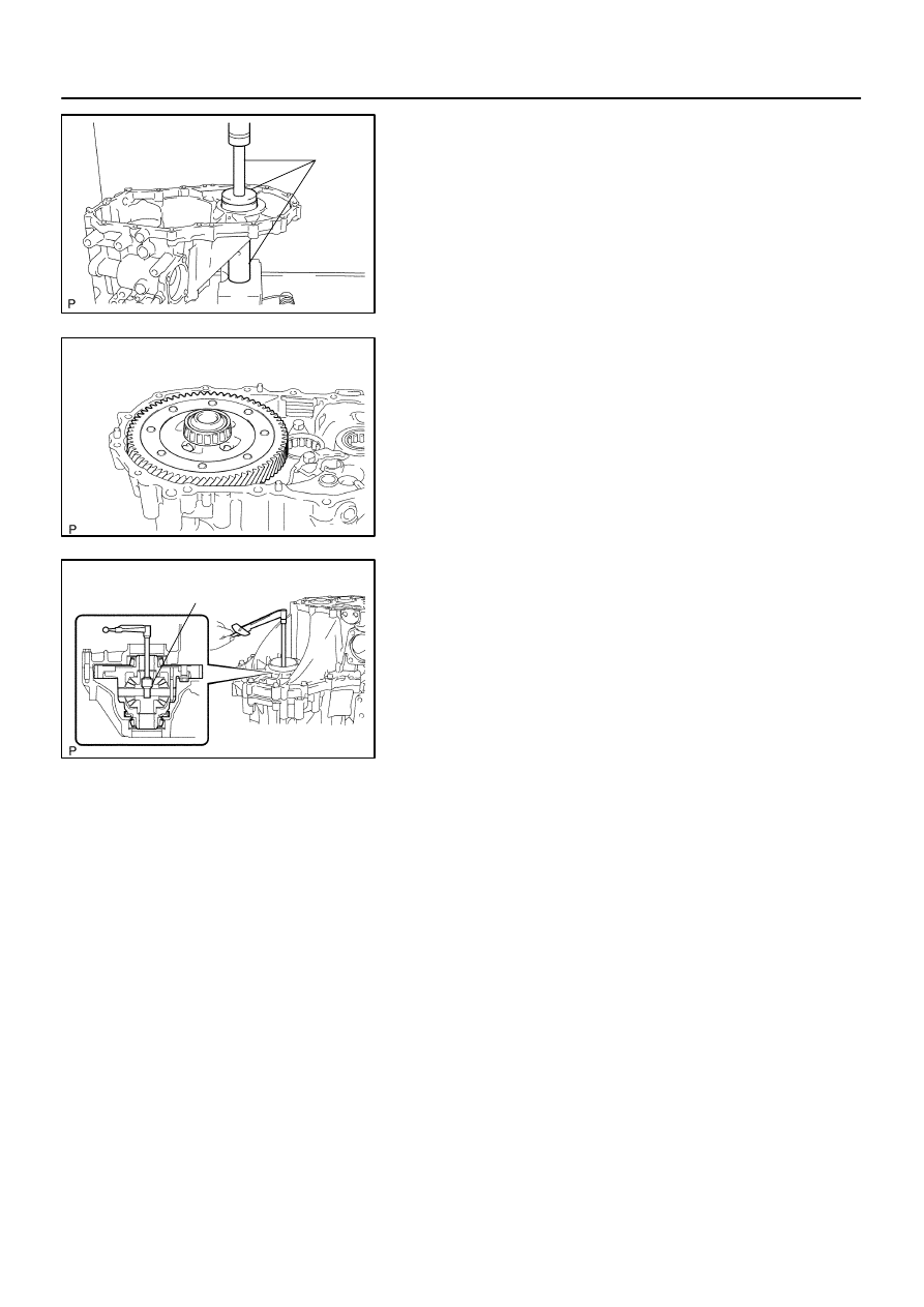
48.
REMOVE OUTPUT SHAFT (MTM) COVER
(a)
Remove the output shaft (MTM) cover from the transaxle
case.
49.
REMOVE FR DIFFERENTIAL CASE FRONT TAPERED
ROLLER BEARING
(a)
Using SST, remove the FR differential case front tapered
roller bearing (outer race) and shim from the transaxle
case.
SST
09612–65014 (09612–01040, 09612–01050)
(b)
Using SST, remove FR differential case front tapered roll-
er bearing (inner race) from the front differential case.
SST
09950–00020, 09950–00030, 09950–40011
(09957–04010), 09950–60010 (09951–00360)
NOTICE:
Be careful not to damage bearing.
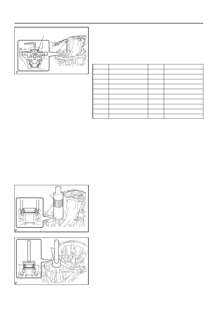
50.
REMOVE TRANSAXLE CASE OIL SEAL
(a)
Using SST and a hammer, drive out the transaxle case oil
seal from the transaxle case.
SST
09950–60010 (09951–00530), 09950–70010
(09951–07150)
51.
REMOVE FR DIFFERENTIAL CASE REAR TAPERED
ROLLER BEARING
(a)
Using SST, remove the FR differential case rear tapered
roller bearing (outer race) and shim from the manual
transmission case.
SST
09612–65014 (09612–01040, 09612–01050)
C95108
SST
C81787
SST
C67848
C67850
41–42
–
MANUAL TRANSMISSION/TRANSAXLE
MANUAL TRANSAXLE ASSY (C59)
1442
Author:
Date:
2004 COROLLA (RM1037U)
(b)
Using SST and a hammer, remove the FR differential
case rear tapered roller bearing (inner race) from the front
differential case.
SST
09950–40011 (09951–04010, 09952–04010,
09953–04020, 09954–04010, 09955–04061,
09957–04010, 09958–04011), 09950–60010
(09951–00360)
NOTICE:
Be careful not to damage bearing.
52.
REMOVE TRANSMISSION CASE OIL SEAL
(a)
Using SST and a hammer, remove the transmission case
oil seal from the manual transmission case.
SST
09950–60010 (09951–00600), 09950–70010
(09951–07100)
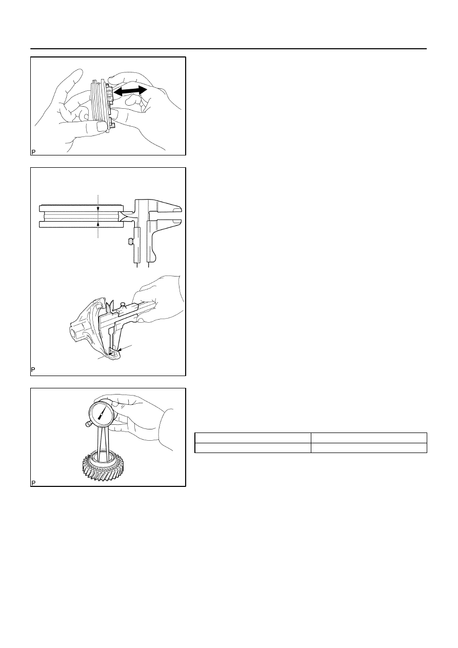
53.
INSPECT SYNCHRONIZER RING NO.3
(a)
Check for wear or damage.
(b)
Check the braking effect of the synchronizer ring. Turn the
synchronizer ring in one direction while pushing it to the
gear cone, check that the ring locks.
If the braking effect is insufficient, apply a small amount of the
fine lapping compound between the synchronizer ring and gear
cone. Lightly rub the synchronizer ring and gear cone together.
NOTICE:
Ensure the file lapping compound is completely washed off
after rubbing.
(c)
Check again the breaking effect of the synchronizer ring.
(d)
Using a feeler gauge, measure the clearance between
the synchronizer ring back and gear spline end.
Minimum clearance: 0.75 mm (0.0295 in.)
If the clearance is less than minimum, replace the synchronizer
ring and gear cone by applying a small amount of the fine lap-
ping compound on gear cone.
NOTICE:
Ensure the fine lapping compound is completely washed
off after rubbing.
C67978
C80375
A
B
Clearance= (A – B)
C67975
–
MANUAL TRANSMISSION/TRANSAXLE
MANUAL TRANSAXLE ASSY (C59)
41–43
1443
Author:
Date:
2004 COROLLA (RM1037U)
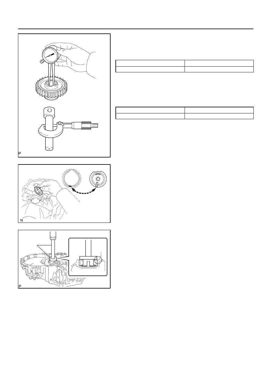
54.
INSPECT TRANSMISSION HUB SLEEVE NO.3
(a)
Check the sliding condition between the transmission hub
sleeve No. 3 and transmission clutch hub No.3.
(b)
Check that spline gear’s of the transmission hub sleeve
No.3 is not worn down.
(c)
Using a vernier calipers, inspect the transmission hub
sleeve No.3 and gear shift fork No.3 as shown in the il-
lustration.
Standard clearance:
0.3 – 0.5 mm (0.012 – 0.020 in.)
If the clearance is out of specification, replace the transmission
hub sleeve No.3 and gear shift fork No.3.
55.
INSPECT 5TH GEAR
(a)
Using a caliper gauge, inspect 5th gear as shown in the
illustration.
5th gear inner diameter:
Standard inner diameter: mm (in.)
Maximum inner diameter: mm (in.)
29.915 – 29.931 (1.1778 – 1.1783)
29.931 (1.1783)
If the inner diameter exceeds the maximum, replace the 5th
gear.
C67846
C95191
Case
Cover
C80376
SST
41–44
–
MANUAL TRANSMISSION/TRANSAXLE
MANUAL TRANSAXLE ASSY (C59)
1444
Author:
Date:
2004 COROLLA (RM1037U)
56.
INSPECT REVERSE IDLER GEAR SUB–ASSY
(a)
Using a caliper gauge, inspect the reverse idler gear sub–
assy as shown in the illustration.
Reverse idler gear sub–assy inner diameter:
Standard inner diameter: mm (in.)
Maximum inner diameter: mm (in.)
18.040 – 18.058 (0.7102 – 0.7109)
18.058 (0.7109)
If the inner diameter exceeds the maximum, replace the re-
verse idler gear sub–assy.
(b)
Using a micrometer, inspect the reverse idler gear shaft
as shown in the illustration.
Reverse idler gear shaft outer diameter:
Standard inner diameter: mm (in.)
Minimum outer diameter: mm (in.)
17.966 – 17.984 (0.7073 – 0.7080)
17.966 (0.7073)
If the outer diameter is below the minimum, replace the reverse
idler gear shaft.
57.
INSTALL OUTPUT SHAFT (MTM) COVER
(a)
Coat the output shaft (MTM) cover with MP grease, install
it to the transaxle case.
NOTICE:
Install the output shaft (MTM) cover projection into the case
side hollow.
58.
INSTALL OUTPUT SHAFT FRONT BEARING
(a)
Coat a new output shaft front bearing with gear oil, using
SST and a press, install it to the transaxle case.
SST
09950–60010 (09951–00550), 09950–70010
(09951–07150)
NOTICE:
Be sure to install a new bearing in the correct direc-
tion, as shown in the illustration.
When replacing the output shaft front bearing, re-
place the output shaft front bearing inner race along
with it.
C81790
SST
C95192
SST
C95110
SST
C80379
SST
C95111
SST
–
MANUAL TRANSMISSION/TRANSAXLE
MANUAL TRANSAXLE ASSY (C59)
41–45
1445
Author:
Date:
2004 COROLLA (RM1037U)
59.
INSTALL FRONT TRANSAXLE CASE OIL SEAL
(a)
Using SST and a hammer, install a new front transaxle
case oil seal to the transaxle case.
SST
09950–60010 (09951–00370), 09950–70010
(09951–07150)
Drive in depth: 15.6 – 16.0 mm (0.6142 – 0.6299 in.)
(b)
Coat the lip of the front transaxle case oil seal with MP
grease.
60.
INSTALL INPUT SHAFT FRONT BEARING
(a)
Coat a new input shaft front bearing with MP grease, us-
ing SST and a press, install it to the transaxle case.
SST
09950–60010 (09951–00420), 09950–70010
(09951–07150)
Drive in depth: 0 – 0.3 mm (0 – 0.012 in.)
61.
INSTALL FR DIFFERENTIAL CASE FRONT TAPERED
ROLLER BEARING
(a)
Using SST and a press, install a new FR differential case
front tapered roller bearing (inner race) to the front differ-
ential case.
SST
09350–32014 (09351–32120), 09950–60010
(09951–00530)
(b)
Using SST and a press, install a new FR differential case
front tapered roller bearing (outer race) with shim to the
transaxle case.
SST
09950–60020 (09951–00680), 09950–70010
(09951–07150)
62.
INSTALL FR DIFFERENTIAL CASE REAR TAPERED
ROLLER BEARING
(a)
Using SST and a press, install a new FR differential case
rear tapered roller bearing (inner race) to the front differ-
ential case.
SST
09350–32014 (09351–32120), 09950–60010
(09951–00530)
C81792
SST
C67656
C81793
SST
41–46
–
MANUAL TRANSMISSION/TRANSAXLE
MANUAL TRANSAXLE ASSY (C59)
1446
Author:
Date:
2004 COROLLA (RM1037U)
(b)
Using SST and a press, install a new FR differential case
rear tapered roller bearing (outer race) with shim to the
manual transmission case.
SST
09309–36010, 09950–60020 (09951–00710),
09950–70010 (09951–07150)
HINT:
Use a shim of the same thickness with the removed one.
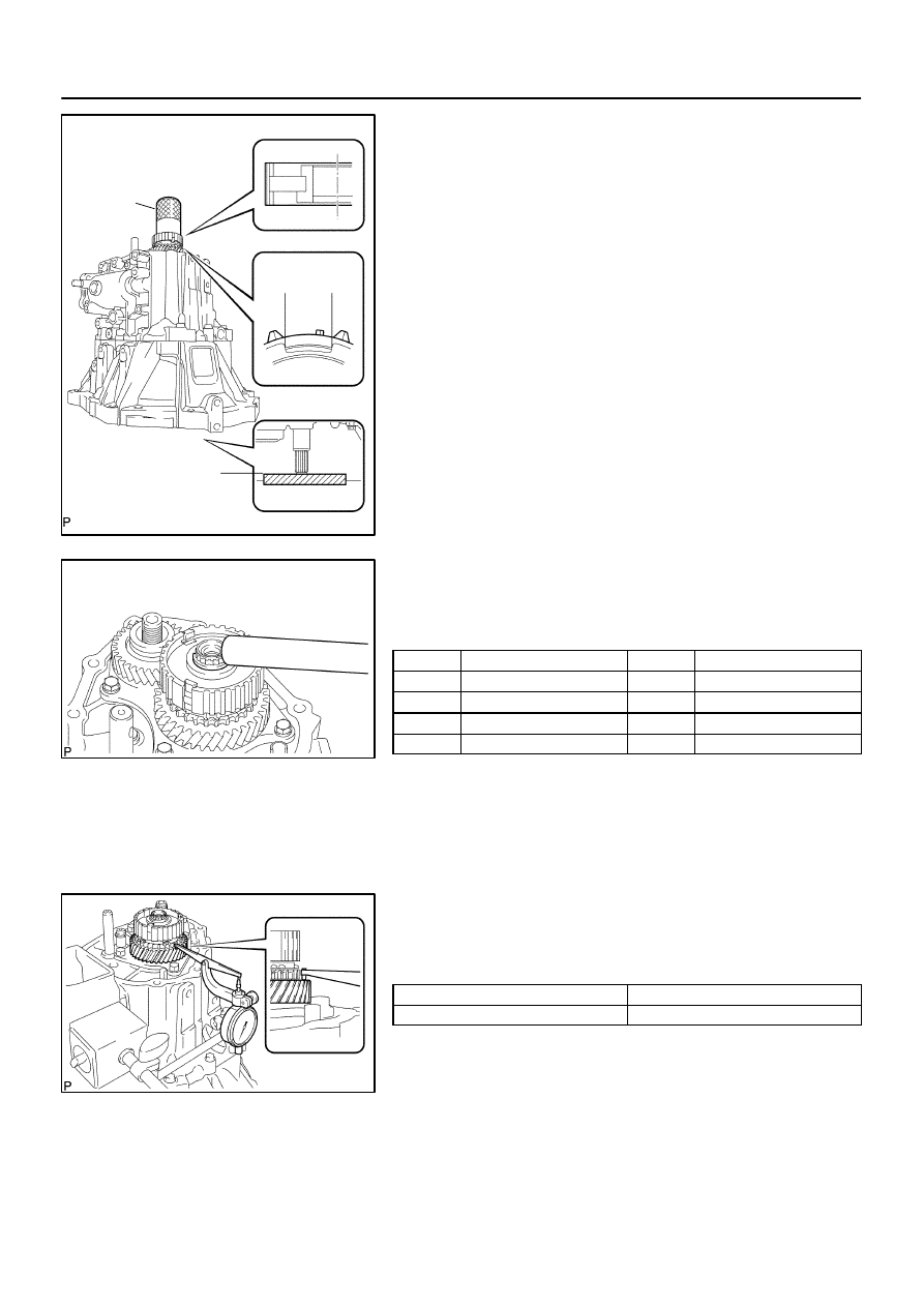
63.
ADJUST DIFFERENTIAL SIDE BEARING RRELOAD
(a)
Coat the differential case assy with gear oil, install it to the
transaxle case.
(b)
Install the manual transmission case with 16 bolts.
Torque: 29.4 N
⋅
m (300 kgf
⋅
cm, 22 ft
⋅
lbf)
(c)
Using SST and a torque wrench, turn the differential case
assy to the right and left 2 or 3 times to allow the bearings
to settle.
SST
09564–32011
C81793
SST
C80381
SST
C80382
SST
–
MANUAL TRANSMISSION/TRANSAXLE
MANUAL TRANSAXLE ASSY (C59)
41–47
1447
Author:
Date:
2004 COROLLA (RM1037U)
(d)
Using SST and a torque wrench, measure the preload.
SST
09564–32011
Preload (at starting):
New bearing:
0.78 – 1.57 N
⋅
m (8 – 16 kgf
⋅
cm, 6.9 – 13.9 in.
⋅
lbf)
If the preload is out of specification, select another shim.
Shim thickness:
Mark
Thickness: mm (in.)
Mark
Thickness: mm (in.)
AA
2.10 (0.0827)
LL
2.60 (0.1024)
BB
2.15 (0.0846)
MM
2.65 (0.1043)
CC
2.20 (0.0866)
NN
2.70 (0.1063)
DD
2.25 (0.0886)
PP
2.75 (0.1083)
EE
2.30 (0.0906)
2.80 (0.1102)
FF
2.35 (0.0925)
RR
2.85 (0.1122)
GG
2.40 (0.0945)
SS
2.90 (0.1142)
HH
2.45 (0.0965)
TT
2.95 (0.1161)
JJ
2.50 (0.0984)
UU
3.00 (0.1181)
KK
2.55 (0.1004)
–
–
HINT:
The preload will change by about 0.3 – 0.4 N
⋅
m (3 – 4 kgf
⋅
cm,
2.6 – 3.5 in.
⋅
lbf) corresponding to a change of 0.05 mm (0.0020
in.) in shim thickness.
(e)
Remove the 16 bolts and manual transmission case from
the transaxle case.
(f)
Remove the differential case assy from the transaxle
case.
64.
INSTALL TRANSMISSION CASE OIL SEAL
(a)
Using SST and a hammer, install a new transmission case
oil seal to the manual transmission case.
SST
09316–60011 (09316–00011)
Drive in depth: 9.9
0.3 mm (0.390
0.012 in.)
(b)
Coat the lip of the transmission case oil seal with MP
grease.
65.
INSTALL TRANSAXLE CASE OIL SEAL
(a)
Using SST and a hammer, install a new transaxle case oil
seal in the transaxle case.
SST
09710–20011 (09710–06071), 09950–70010
(09951–07150)
Drive in depth: 1.9
0.3 mm (0.075
0.012 in.)
(b)
Coat the lip of the transaxle case oil seal with MP grease.
C67659
C67658
C68380
C95781
C80383
41–48
–
MANUAL TRANSMISSION/TRANSAXLE
MANUAL TRANSAXLE ASSY (C59)
1448
Author:
Date:
2004 COROLLA (RM1037U)
66.
INSTALL TRANSMISSION MAGNET
(a)
Clean the transmission magnet, install it to the transaxle
case.
67.
INSTALL BEARING LOCK PLATE
(a)
Install the bearing lock plate with the bolt.
Torque: 11.3 N
⋅
m (115 kgf
⋅
cm, 8 ft
⋅
lbf)
68.
INSTALL OIL RECEIVER PIPE NO.1 (MTM)
(a)
Install the oil receiver pipe No.1 (MTM) with bolt to the
manual transmission case.
Torque: 17.2 N
⋅
m (175 kgf
⋅
cm, 13 ft
⋅
lbf)
NOTICE:
Prevent the oil receiver pipe No.1 (MTM) from being
deformed.
Install the oil receiver pipe No.1 (MTM) while placing
it against the manual transmission case, as shown in
the illustration.
69.
INSTALL OIL RECEIVER PIPE NO.2 (MTM)
(a)
Install the oil receiver pipe No.2 (MTM) with bolt to the
manual transmission case.
Torque: 17.2 N
⋅
m (175 kgf
⋅
cm, 13 ft
⋅
lbf)
NOTICE:
Prevent the oil receiver pipe No.2 (MTM) from being
deformed.
Install the oil receiver pipe No.2 (MTM) while placing
it against the manual transmission case, as shown in
the illustration.
70.
INSTALL REVERSE RESTRICT PIN ASSY
(a)
Install the reverse restrict pin assy to the manual trans-
mission case.
NOTICE:
Do not set the reverse restrict pin assy in incorrect orienta-
tion.
C80384
A
C80385
C67657
C67656
C80370
–
MANUAL TRANSMISSION/TRANSAXLE
MANUAL TRANSAXLE ASSY (C59)
41–49
1449
Author:
Date:
2004 COROLLA (RM1037U)
(b)
Using a pin punch (
φ
5 mm) and hammer, install the
slotted pin to the reverse restrict pin assy.
Drive in depth (A):
15.5 – 16.5 mm (0.6102 – 0.6496 in.)
(c)
Apply sealant to the reverse restrict pin plug.
Sealant:
Part No. 08833–00080, THREE BOND 1344, LOCTITE
242 or equivalent
(d)
Using a hexagon wrench and a torque wrench, install the
reverse restrict pin plug to the manual transmission case.
Torque: 12.7 N
⋅
m (130 kgf
⋅
cm, 9 ft
⋅
lbf)
71.
INSTALL MANUAL TRANSAXLE CASE RECEIVER
(a)
Install the manual transaxle case receiver with the bolt to
the transaxle case.
Torque: 11.3 N
⋅
m (115 kgf
⋅
cm, 8 ft
⋅
lbf)
72.
INSTALL DIFFERENTIAL CASE ASSY
(a)
Coat the differential case tapered roller bearing with gear
oil, install the differential case assy to the transaxle case.
73.
INSTALL INPUT SHAFT ASSY
(a)
Coat the sliding and rotating surface of the input and out
put shafts with gear oil, install them to the transaxle case.
C80386
Align Alignment Mark
C80387
Gear Shift
Fork No.2
Gear Shift
Fork No.1
C80388
Gear Shift
Fork Shaft
No.1
C80389
C80450
41–50
–
MANUAL TRANSMISSION/TRANSAXLE
MANUAL TRANSAXLE ASSY (C59)
1450
Author:
Date:
2004 COROLLA (RM1037U)
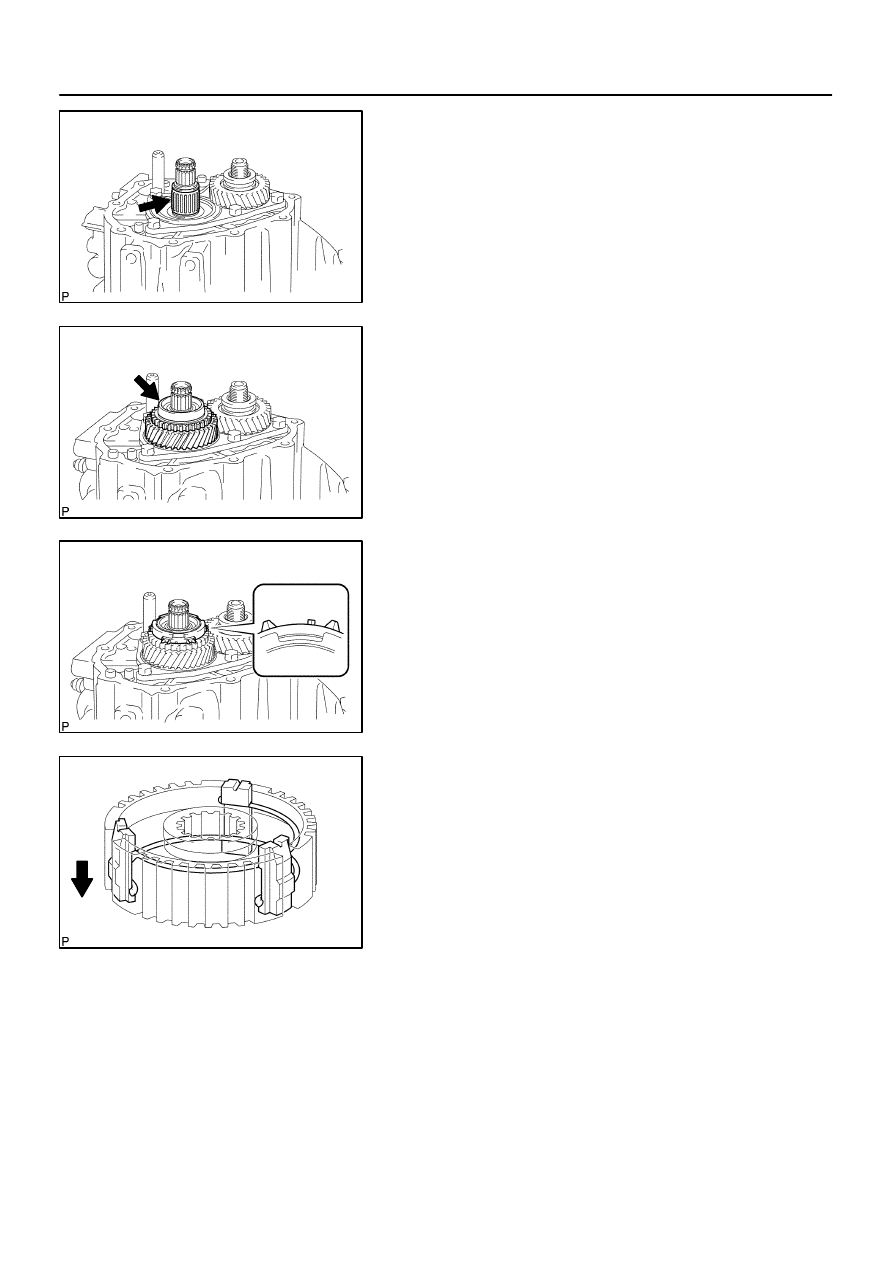
74.
INSTALL REVERSE IDLER GEAR SUB–ASSY
(a)
Coat the reverse idler gear sub–assy, thrust washer and
reverse idler gear shaft with gear oil, install them as
shown in the illustration.
HINT:
Align the mark on the reverse idler gear shaft with the bolt hole
shown in the illustration.
75.
INSTALL GEAR SHIFT FORK SHAFT SUB–ASSY NO.1
(a)
Coat the gear shift fork No.1 and gear shift fork No.2 with
gear oil, install them.
(b)
Coat the gear shift fork shaft sub–assy No.1 with gear oil,
install it.
(c)
Apply sealant to the shift fork lock bolt.
Sealant:
Part No. 08833–00080, THREE BOND 1344, LOCTITE
242 or equivalent
(d)
Install the gear shift fork lock bolt.
Torque: 15.7 N
⋅
m (160 kgf
⋅
cm, 12 ft
⋅
lbf)
(e)
Using a brass bar and a hammer, install the shaft snap
ring to the gear shift fork shaft No.1.
76.
INSTALL GEAR SHIFT FORK SHAFT NO.3
(a)
Coat the 2 balls with MP grease, install them to the re-
verse shift fork.
(b)
Install the reverse shift fork to the gear shift fork shaft
No.3.
C80391
C80392
C80362
C95193
C80361
–
MANUAL TRANSMISSION/TRANSAXLE
MANUAL TRANSAXLE ASSY (C59)
41–51
1451
Author:
Date:
2004 COROLLA (RM1037U)
(c)
Using a brass bar and a hammer, install the 2 shift fork
shaft snap rings to the gear shift fork shaft No.3.
(d)
Coat the gear shift fork shaft No.3 with gear oil, install it.
77.
INSTALL GEAR SHIFT FORK SHAFT NO.2
(a)
Coat the gear shift head No.1 and gear shift fork shaft
No.2 with gear oil, install them.
NOTICE:
To avoid the interference of the 2 shift fork balls, lift up the
gear shift fork shaft NO.3 at the position shown in the il-
lustration.
(b)
Coat the 2 shift lock bolts with sealant, install then to the
gear shift fork No.2 and gear shift head No.1.
Sealant:
Part No. 08833–00080, THREE BOND 1344, LOCTITE
242 or equivalent
Torque: 15.7 N
⋅
m (160 kgf
⋅
cm, 12 ft
⋅
lbf)
C80360
C82142
FIPG
C80358
C80357
C67639
41–52
–
MANUAL TRANSMISSION/TRANSAXLE
MANUAL TRANSAXLE ASSY (C59)
1452
Author:
Date:
2004 COROLLA (RM1037U)
78.
INSTALL REVERSE SHIFT ARM BRACKET ASSY
(a)
Install the reverse shift arm bracket assy with 2 bolts to the
transaxle case.
Torque: 17.2 N
⋅
m (175 kgf
⋅
cm, 13 ft
⋅
lbf)
79.
INSTALL MANUAL TRANSMISSION CASE
(a)
Apply FIPG to the manual transmission case, as shown
in the illustration.
FIPG:
Part No. 08826–00090, THREE BOND 1281 or equiva-
lent
NOTICE:
Parts must be assembled within 10 minutes of application.
Otherwise, the packing (FIPG) material must be removed
and reapplied.
(b)
Coat the 13 bolts with sealant, install them to the manual
transmission case.
Sealant:
Part No. 08833–00080, THREE BOND 1344, LOCTITE
242 or equivalent
Torque: 29.4 N
⋅
m (300 kgf
⋅
cm, 22 ft
⋅
lbf)
(c)
Coat the 3 bolts with sealant, install them to the transaxle
case.
Sealant:
Part No. 08833–00080, THREE BOND 1344, LOCTITE
242 or equivalent
Torque: 29.4 N
⋅
m (300 kgf
⋅
cm, 22 ft
⋅
lbf)
80.
INSTALL REVERSE IDLER GEAR SHAFT BOLT
(a)
Coat the reverse idler gear shaft bolt with sealant, install
it with a new gasket.
Sealant:
Part No. 08833–00080, THREE BOND 1344, LOCTITE
242 or equivalent
Torque: 29.4 N
⋅
m (300 kgf
⋅
cm, 22 ft
⋅
lbf)
C80356
C68417
C67634
C80393
C80354
–
MANUAL TRANSMISSION/TRANSAXLE
MANUAL TRANSAXLE ASSY (C59)
41–53
1453
Author:
Date:
2004 COROLLA (RM1037U)
81.
INSTALL LOCK BALL ASSY NO.1
(a)
Coat the lock ball assy No.1 with sealant, install it with us-
ing a hexagon wrench.
Sealant:
Part No. 08833–00080, THREE BOND 1344, LOCTITE
242 or equivalent
Torque: 39.2 N
⋅
m (400 kgf
⋅
cm, 29 ft
⋅
lbf)
82.
INSTALL SHIFT DETENT BALL
(a)
Install the 2 shift detent balls, 2 springs with 2 seats to the
manual transmission case.
(b)
Coat the 2 shift detent ball plugs with sealant, install them
with using a hexagon wrench.
Sealant:
Part No. 08833–00080, THREE BOND 1344, LOCTITE
242 or equivalent
Torque: 24.5 N
⋅
m (250 kgf
⋅
cm, 18 ft
⋅
lbf)
(c)
Install the shift detent ball, spring and seat to the transaxle
case.
(d)
Coat the shift detent ball plug with sealant, install it with
using a hexagon wrench.
Sealant:
Part No. 08833–00080, THREE BOND 1344, LOCTITE
242 or equivalent
Torque: 24.5 N
⋅
m (250 kgf
⋅
cm, 18 ft
⋅
lbf)
C80352
C80351
C80394
C80350
C95786
SST
SST
41–54
–
MANUAL TRANSMISSION/TRANSAXLE
MANUAL TRANSAXLE ASSY (C59)
1454
Author:
Date:
2004 COROLLA (RM1037U)
83.
INSTALL INPUT SHAFT REAR BEARING HOLE SNAP
RING
(a)
Using a snap ring expander, install the input shaft rear
bearing hole snap ring to the input shaft.
84.
INSTALL OUTPUT SHAFT REAR BEARING HOLE
SNAP RING
(a)
Using a snap ring expander, install the output shaft rear
bearing hole snap ring to the output shaft.
85.
INSTALL SHIFT FORK SHAFT SHAFT SNAP RING
(a)
Using a brass bar and a hammer, install the shift fork shaft
shaft snap ring to the shift fork shaft No.2.
86.
INSTALL BEARING RETAINER REAR (MTM)
(a)
Coat the 5 bolts with sealant, install them and bearing re-
tainer rear (MTM) to the manual transmission case.
Torque: 27.4 N
⋅
m (279 kgf
⋅
cm, 20 ft
⋅
lbf)
87.
INSTALL 5TH DRIVEN GEAR
(a)
Using SST, install the 5th driven gear to the output shaft.
SST
09309–12020
C80348
C80396
C80397
Key position
C80398
Engine
Side
–
MANUAL TRANSMISSION/TRANSAXLE
MANUAL TRANSAXLE ASSY (C59)
41–55
1455
Author:
Date:
2004 COROLLA (RM1037U)
88.
INSTALL 5TH GEAR NEEDLE ROLLER BEARING
(a)
Coat the 5th gear needle roller bearing and 5th gear bear-
ing spacer with gear oil, install them to the input shaft.
89.
INSTALL 5TH GEAR
(a)
Coat the 5th gear with gear oil, install it to the input shaft.
90.
INSTALL SYNCHRONIZER RING NO.3
(a)
Coat the synchronizer ring No.3 with gear oil, install it to
the 5th gear.
91.
INSTALL TRANSMISSION CLUTCH HUB NO.3
(a)
Install the 3 synchromesh shifting keys and 2 synchro-
mesh shifting key springs to the transmission clutch hub
No.3.
HINT:
Do not set both openings of the shifting key springs in the same
position.
C80399
Key position
SST
Wooden Block
C80400
C80344
41–56
–
MANUAL TRANSMISSION/TRANSAXLE
MANUAL TRANSAXLE ASSY (C59)
1456
Author:
Date:
2004 COROLLA (RM1037U)
(b)
Using SST and a hammer, install the transmission clutch
hub No.3 to the input shaft.
SST
09636–20010
HINT:
Before driving in the No.3 clutch hub assy, place the suit-
able sized wooden block on the rear side of the input
shaft, as shown in the illustration.
When driving it in, fix the input shaft firmly so that it is not
pushed downward. Otherwise the input shaft rear bearing
is over loaded, it might be damaged.
(c)
Select a snap ring from the table below that will make the
thrust clearance of the transmission clutch hub No.3 be-
low 0.1 mm (0.0039 in.).
Snap ring thickness:
Mark
Thickness: mm (in.)
Mark
Thickness: mm (in.)
A
2.25 (0.0886)
E
2.49 (0.0980)
B
2.31 (0.0909)
F
2.55 (0.1004)
C
2.37 (0.0933)
G
2.61 (0.1028)
D
2.43 (0.0957)
–
–
(d)
Using a brass bar and a hammer, install the snap ring to
the input shaft.
92.
INSPECT 5TH GEAR THRUST CLEARANCE
(a)
Using a dial indicator, measure the 5th gear thrust clear-
ance.
5th gear thrust clearance:
Standard clearance: mm (in.)
Maximum clearance: mm (in.)
0.10 – 0.57 (0.0039 – 0.0224)
0.57 (0.0224)
C80345
C80401
C80402
C80403
–
MANUAL TRANSMISSION/TRANSAXLE
MANUAL TRANSAXLE ASSY (C59)
41–57
1457
Author:
Date:
2004 COROLLA (RM1037U)
93.
INSPECT 5TH GEAR RADIAL CLEARANCE
(a)
Using a dial indicator, measure the 5th gear radial clear-
ance.
5th gear radial clearance:
Standard clearance: mm (in.)
Maximum clearance: mm (in.)
KOYO made:
0.015 – 0.058 (0.0006 – 0.0023)
KOYO made: 0.058 (0.0023)
NSK made:
0.015 – 0.056 (0.0006 – 0.0022)
NSK made: 0.056 (0.0022)
If the clearance exceed the maximum value, replace the gear,
needle roller bearing or shaft.
94.
INSTALL GEAR SHIFT FORK NO.3
(a)
Coat the transmission clutch hub sleeve No.3 with gear
oil, install it and gear shift fork No.3 to the transmission
clutch hub No.3.
HINT:
Do not set the transmission clutch hub No.3 in incorrect orienta-
tion.
(b)
Coat the gear shift lock fork ball with sealant, install it to
the gear shift fork No.3.
Sealant:
Part No. 08833–00080, THREE BOND 1344, LOCTITE
242 or equivalent
Torque: 15.7 N
⋅
m (160 kgf
⋅
cm, 12 ft
⋅
lbf)
95.
INSTALL MANUAL TRANSMISSION OUTPUT SHAFT
REAR SET NUT
(a)
Engage the gear double meshing.
(b)
Install a new manual transmission output shaft rear set
nut.
Torque: 117.6 N
⋅
m (1,200 kgf
⋅
cm, 87 ft
⋅
lbf)
C80404
C95194
FIPG
C95310
C95187
41–58
–
MANUAL TRANSMISSION/TRANSAXLE
MANUAL TRANSAXLE ASSY (C59)
1458
Author:
Date:
2004 COROLLA (RM1037U)
(c)
Using a chisel and a hammer, stake the manual transmis-
sion output shaft rear set nut.
(d)
Disengage the gear double meshing.
96.
INSTALL MANUAL TRANSMISSION CASE COVER
SUB–ASSY
(a)
Apply FIPG to the manual transmission case cover sub–
assy as shown in the illustration.
FIPG:
Part No. 08826–00090, THREE BOND 1281 or equiva-
lent
NOTICE:
Parts must be assembled within 10 minutes of application.
Otherwise, the packing (FIPG) material
must be removed
and reapplied.
(b)
Install the manual transmission case cover sub–assy with
the 9 bolts to the manual transmission case.
Torque: 18.1 N
⋅
m (185 kgf
⋅
cm, 14 ft
⋅
lbf)
97.
INSTALL SHIFT & SELECT LEVER SHAFT ASSY
(a)
Coat the 4 bolts with sealant, install them, new gasket and
shift & select lever shaft assy to the manual transmission
case.
Sealant:
Part No. 08833–00080, THREE BOND 1344, LOCTITE
242 or equivalent
Torque: 19.6 N
⋅
m (200 kgf
⋅
cm, 14 ft
⋅
lbf)
NOTICE:
Set the claws of the shift interlock plate into the shift head
part of the gear shift fork shaft securely.
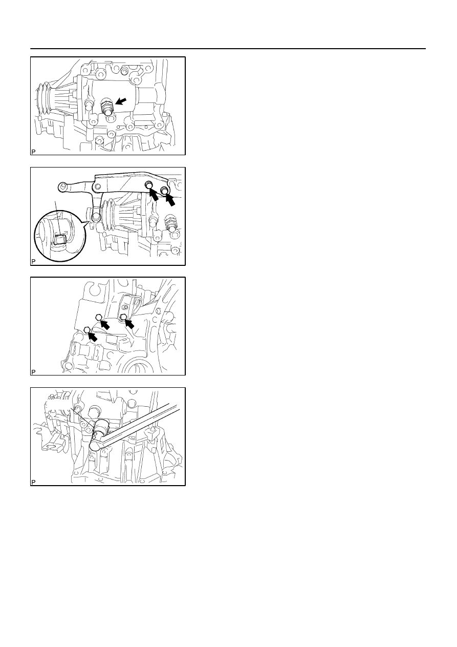
C95186
C95185
(A)
C80333
C80406
SST
–
MANUAL TRANSMISSION/TRANSAXLE
MANUAL TRANSAXLE ASSY (C59)
41–59
1459
Author:
Date:
2004 COROLLA (RM1037U)
98.
INSTALL LOCK BALL ASSY NO.1
(a)
Coat the lock ball assy No.1 with sealant, install it to the
manual transmission case.
Sealant:
Part No. 08833–00080, THREE BOND 1344, LOCTITE
242 or equivalent
Torque: 29.4 N
⋅
m (300 kgf
⋅
cm, 22 ft
⋅
lbf)
99.
INSTALL SELECTING BELL CRANK ASSY
(a)
Install the selecting bellcrank assy with control shift lever
bush with the 2 bolts to the manual transmission case.
Torque: 24.5 N
⋅
m (250 kgf
⋅
cm, 18 ft
⋅
lbf)
NOTICE:
Apply MP grease to the inside circumferential surface of
the control shift lever bush (A).
100. INSTALL FLOOR SHIFT CONTROL LEVER HOUSING
SUPPORT BRACKET
(a)
Install the floor shift control lever housing support bracket
with the 3 bolts to the transaxle case.
Torque: 11.3 N
⋅
m (115 kgf
⋅
cm, 8 ft
⋅
lbf)
101. INSTALL BACK UP LAMP SWITCH ASSY
(a)
Using SST, install the backup lamp switch assy with a new
gasket to the manual transmission case.
Torque: 40.2 N
⋅
m (410 kgf
⋅
cm, 30 ft
⋅
lbf)
SST
09817–16011
102. INSTALL SPEEDOMETER DRIVEN HOLE COVER SUB–ASSY (W/ ABS)
(a)
Install a new O–ring to the speedometer driver hole cover sub–assy.
(b)
Install the speedometer driver hole cover sub–assy with the bolt.
Torque: 11.3 N
⋅
m (115 kgf
⋅
cm, 8 ft
⋅
lbf)
103. INSTALL SPEEDOMETER DRIVEN (MTM) GEAR SUB–ASSY (W/O ABS)
(a)
Install the speedometer driven (MTM) gear sub–assy with clip to the speedometer sensor.
104. INSTALL SPEEDOMETER SENSOR (W/O ABS)
(a)
Install a new O–ring to the speedometer sensor.
(b)
Install the speedometer sensor with the bolt.
Torque: 11.3 N
⋅
m (115 kgf
⋅
cm, 8 ft
⋅
lbf)
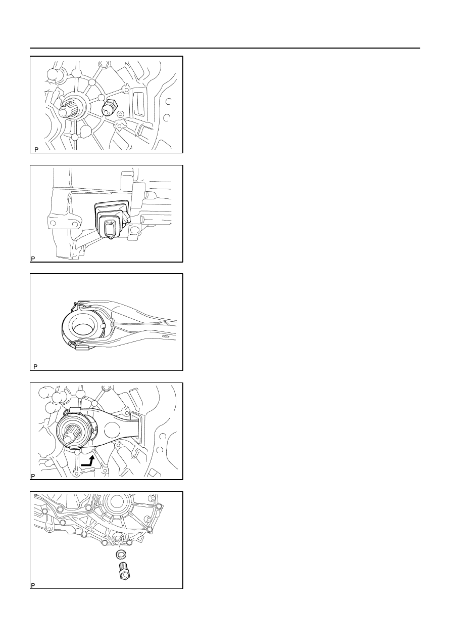
C67604
C80331
C67602
C68381
C80550
41–60
–
MANUAL TRANSMISSION/TRANSAXLE
MANUAL TRANSAXLE ASSY (C59)
1460
Author:
Date:
2004 COROLLA (RM1037U)
105. INSTALL RELEASE FORK SUPPORT
(a)
Install the release fork support to the transaxle case.
Torque: 36.8 N
⋅
m (375 kgf
⋅
cm, 25 ft
⋅
lbf)
106. INSTALL CLUTCH RELEASE FORK BOOT
(a)
Install the clutch release fork boot to the transaxle case.
107. INSTALL CLUTCH RELEASE BEARING ASSY
(a)
Coat the clutch release bearing assy with the release hub
grease, install it to the clutch release fork sub–assy.
Sealant:
Part No. 08887–01806, RELEASE HUB GREASE or
equivalent
108. INSTALL CLUTCH RELEASE FORK SUB–ASSY
(a)
Install the clutch release fork sub–assy to the input shaft.
(b)
Apply clutch spline grease to spline of the input shaft.
Sealant:
Part No. 08887–01806, CLUTCH SPLINE GREASE or
equivalent
109. INSTALL DRAIN (MTM) PLUG SUB–ASSY
(a)
Install a new gasket with the drain (MTM) plug sub–assy.
Torque: 39.2 N
⋅
m (400 kgf
⋅
cm, 29 ft
⋅
lbf)
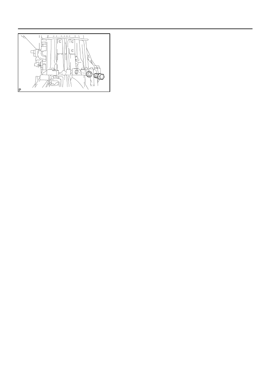
C80549
–
MANUAL TRANSMISSION/TRANSAXLE
MANUAL TRANSAXLE ASSY (C59)
41–61
1461
Author:
Date:
2004 COROLLA (RM1037U)
110. INSTALL MANUAL TRANSMISSION FILLER PLUG
(a)
Install a new gasket with the manual transmission filler
plug.
Torque: 39.2 N
⋅
m (400 kgf
⋅
cm, 29 ft
⋅
lbf)
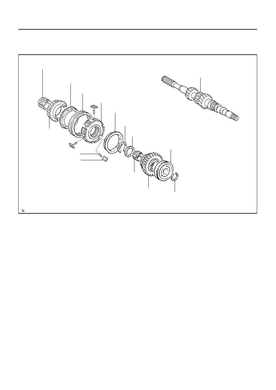
4107G–01
D07720
3rd Gear Needle Roller Bearing
Input Shaft
3rd Gear Synchronizer Ring
Transmission Hub Sleeve No.2
Transmission Clutch Hub No.2
4th Gear Synchronizer Ring
Snap Ring
Input Shaft Rear Radial Ball Bearing
Snap Ring
4th Gear
4th Gear Needle Roller Bearing
Shifting Key No.2
Shifting Key Spring No.2
3rd Gear
4th Gear Bearing Spacer
41–62
–
MANUAL TRANSMISSION/TRANSAXLE
INPUT SHAFT ASSY (C59)
1462
Author:
Date:
2004 COROLLA (RM1037U)
INPUT SHAFT ASSY (C59)
COMPONENTS
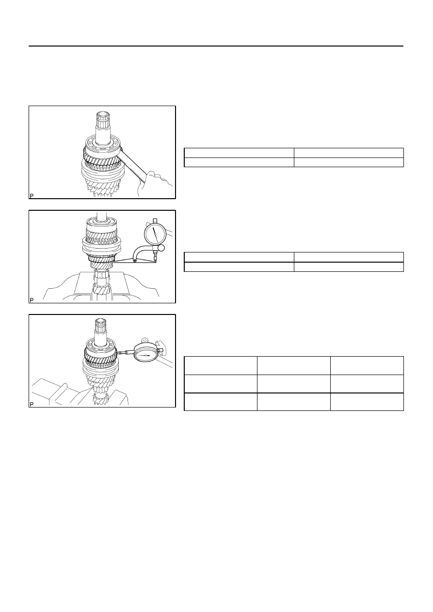
4107H–01
C80557
C67816
C80558
–
MANUAL TRANSMISSION/TRANSAXLE
INPUT SHAFT ASSY (C59)
41–63
1463
Author:
Date:
2004 COROLLA (RM1037U)
OVERHAUL
1.
INSPECT 4TH GEAR THRUST CLEARANCE
(a)
Using a feeler gauge, measure the 4th gear thrust clear-
ance.
4th gear thrust clearance:
Standard clearance: mm (in.)
Maximum clearance: mm (in.)
0.10 – 0.55 (0.0039 – 0.0217)
0.55 (0.0217)
2.
INSPECT 3RD GEAR THRUST CLEARANCE
(a)
Using a dial indicator, measure the 3rd gear thrust clear-
ance.
3rd gear thrust clearance:
Standard clearance: mm (in.)
Maximum clearance: mm (in.)
0.10 – 0.35 (0.0039 – 0.0138)
0.35 (0.0138)
3.
INSPECT 4TH GEAR RADIAL CLEARANCE
(a)
Using a dial indicator, measure the 4th gear radial clear-
ance.
4th gear radial clearance:
Standard clearance:
mm (in.)
Maximum clearance:
mm (in.)
KOYO made
0.015 – 0.058
(0.0006 – 0.0023)
0.058 (0.0023)
NSK made
0.015 – 0.056
(0.0006 – 0.0022)
0.056 (0.0022)
If the clearance exceeds the maximum, replace the gear,
needle roller bearing or shaft.
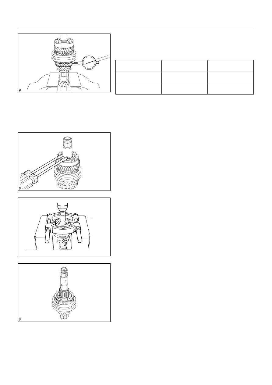
C67815
C80559
Q04983
SST
C80560
41–64
–
MANUAL TRANSMISSION/TRANSAXLE
INPUT SHAFT ASSY (C59)
1464
Author:
Date:
2004 COROLLA (RM1037U)
4.
INSPECT 3RD GEAR RADIAL CLEARANCE
(a)
Using a dial indicator, measure the 3rd gear radial clear-
ance.
3rd gear radial clearance:
Standard clearance:
mm (in.)
Maximum clearance:
mm (in.)
KOYO made
0.015 – 0.058
(0.0006 – 0.0023)
0.058 (0.0023)
NSK made
0.015 – 0.056
(0.0006 – 0.0022)
0.0056 (0.0022)
If the clearance exceeds the maximum, replace the gear,
needle roller bearing or shaft.
5.
REMOVE 4TH GEAR
(a)
Using 2 screwdrivers and a hammer, tap out the snap
ring.
HINT:
Using a waste to prevent the snap ring from being scattered.
(b)
Using SST and a press, remove the input shaft radial ball
bearing rear and 4th gear from the input shaft.
SST
09950–00020
NOTICE:
Do not tighten SST excessively.
Support the input shaft assy by hand so that it will not
be dropped off.
6.
REMOVE 4TH GEAR NEEDLE ROLLER BEARING
(a)
Remove the 4th gear needle roller bearing and 4th gear
bearing spacer from the input shaft.
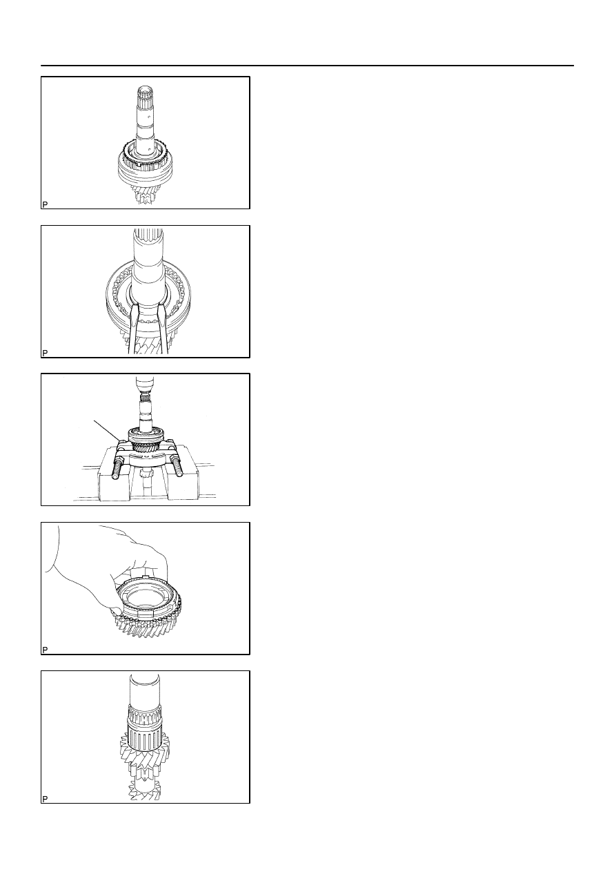
C80561
C67821
CM0064
SST
C68515
C67823
–
MANUAL TRANSMISSION/TRANSAXLE
INPUT SHAFT ASSY (C59)
41–65
1465
Author:
Date:
2004 COROLLA (RM1037U)
7.
REMOVE 4TH GEAR SYNCHRONIZER RING
(a)
Remove the 4th gear synchronizer ring from the transmis-
sion clutch hub No.2.
8.
REMOVE 3RD GEAR
(a)
Using 2 screwdrivers and a hammer, tap out the snap
ring.
HINT:
Using a waste to prevent the snap ring from being scattered.
(b)
Using SST and a press, remove the transmission clutch
hub No.2 and 3rd gear from the input shaft.
SST
09950–00020
NOTICE:
Do not tighten SST excessively.
Support the input shaft by hand so that it will not be
dropped off.
9.
REMOVE 3RD GEAR SYNCHRONIZER RING
(a)
Remove the 3rd gear synchronizer ring from the 3rd gear.
10.
REMOVE 3RD GEAR NEEDLE ROLLER BEARING
(a)
Remove the 3rd gear needle roller bearing from the input
shaft.
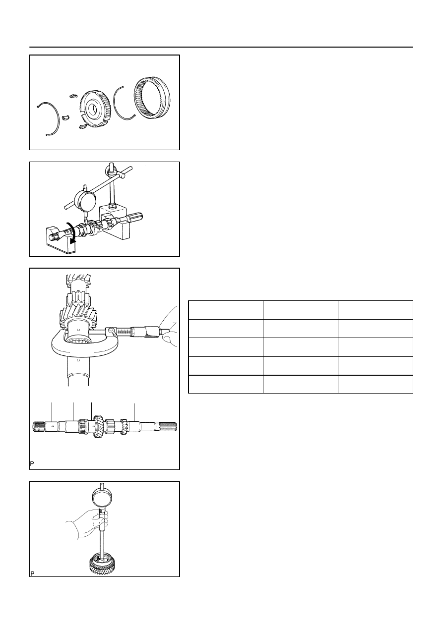
CM0141
CM0013
A
B
C
D
C80562
C67826
41–66
–
MANUAL TRANSMISSION/TRANSAXLE
INPUT SHAFT ASSY (C59)
1466
Author:
Date:
2004 COROLLA (RM1037U)
11.
REMOVE TRANSMISSION HUB SLEEVE NO.2
(a)
Remove the transmission hub sleeve No.2, 3 synchro-
mesh shifting keys and 2 synchromesh shifting key
springs from the transmission clutch hub No.2.
HINT:
Using a waste to prevent the shifting key and shifting key spring
from being scattered.
12.
INSPECT INPUT SHAFT
(a)
Using a dial indicator, check the shaft runout.
Maximum runout: 0.015 mm(0.0006 in.)
If the runout exceeds the maximum, replace the input shaft.
(b)
Using a micrometer, measure the outer diameter of the in-
put shaft journal surface.
Input shaft outer diameter:
Part
Standard outer diameter:
mm (in.)
Minimum outer diameter:
mm (in.)
A
24.885 – 24.900
(0.9797 – 0.9803)
24.885 (0.9797)
B
28.985 – 29.000
(1.1411 – 1.1417)
28.985 (1.1411)
C
30.985 – 31.000
(1.2198 – 1.2204)
30.985 (1.2198)
D
24.985–25.000
(0.9836 – 0.9842)
24.985 (0.9836)
If the outer diameter is below the minimum, replace the input
shaft.
13.
INSPECT 4TH GEAR
(a)
Using a cylinder gauge, measure the inside diameter of
the 4th gear.
Standard inside diameter:
34.015 – 34.031 mm (1.3391 – 1.3398 in.)
Maximum inside diameter:
34.031 mm (1.3398 in.)
If the inside diameter exceeds the maximum, replace the 4th
gear.
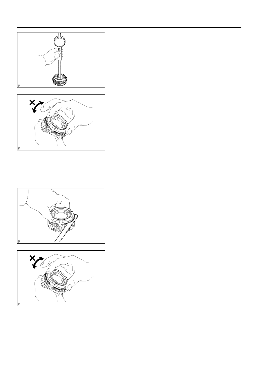
C67827
C80457
C80458
C80457
–
MANUAL TRANSMISSION/TRANSAXLE
INPUT SHAFT ASSY (C59)
41–67
1467
Author:
Date:
2004 COROLLA (RM1037U)
14.
INSPECT 3RD GEAR
(a)
Using a cylinder gauge, measure the inside diameter of
the 3rd gear.
Standard inside diameter:
36.015 – 36.031 mm (1.4179 – 1.4185 in.)
Maximum inside diameter:
36.031 mm (1.4185 in.)
If the inside diameter exceeds the maximum, replace the 3rd
gear.
15.
INSPECT 3RD GEAR SYNCHRONIZER RING
(a)
Check for wear or damage.
(b)
Check the braking effect of the 3rd gear synchronizer ring.
Turn the 3rd gear synchronizer ring in one direction while
pushing it to the gear cone. Check that the ring locks.
If the braking effect is insufficient, apply a small amount of the
fine lapping compound between 3rd gear synchronizer ring and
3rd gear cone. Lightly rub the 3rd gear synchronizer ring and
3rd gear cone together.
NOTICE:
Ensure the fine lapping compound is completely washed
off after rubbing.
(c)
Check again the braking effect of the synchronizer ring.
(d)
Using a feeler gauge, measure the clearance between
3rd gear synchronizer ring back and 3rd gear spline end.
Minimum clearance:
0.65 mm (0.0256 in.)
If the clearance below than the minimum, replace the 3rd gear
synchronizer ring, and apply small amount of the fine lapping
compound on gear cone.
NOTICE:
Ensure the fine lapping compound is completely washed
off after rubbing.
16.
INSPECT 4TH GEAR SYNCHRONIZER RING
(a)
Check for wear or damage.
(b)
Check the braking effect of the 4th gear synchronizer ring.
Turn the 4th gear synchronizer ring in one direction while
pushing it to the gear cone. Check that the ring locks.
If the braking effect is insufficient, apply a small amount of the
fine lapping compound between 4th gear synchronizer ring and
4th gear cone. Lightly rub the 4th gear synchronizer ring and 4th
gear cone.
NOTICE:
Ensure the fine lapping compound is completely washed
off after rubbing.
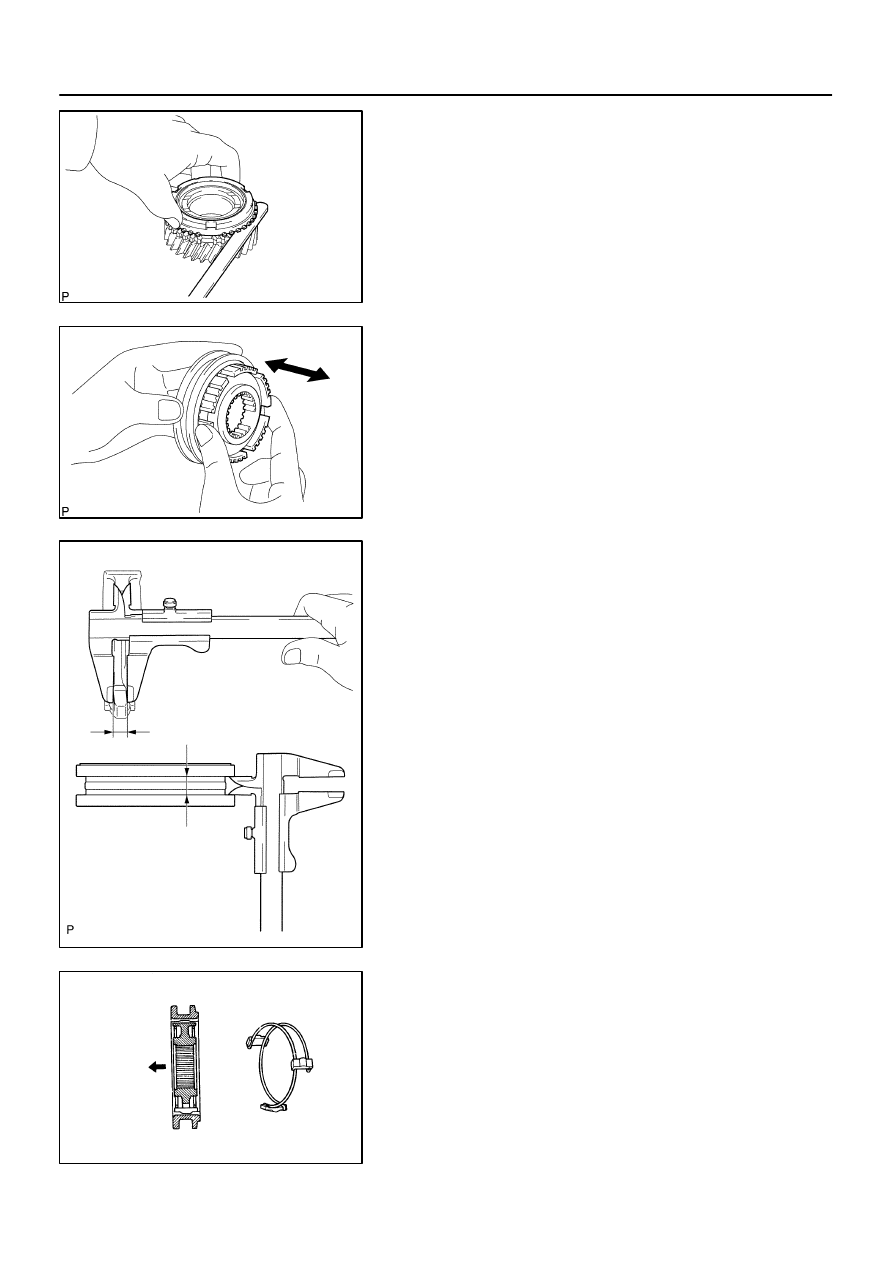
C80458
C67843
C67842
A
B
Clearance= (B–A)
D02999
Engine
Side
41–68
–
MANUAL TRANSMISSION/TRANSAXLE
INPUT SHAFT ASSY (C59)
1468
Author:
Date:
2004 COROLLA (RM1037U)
(c)
Using a feeler gauge, measure the clearance between
4th gear synchronizer ring back and 4th gear spline end.
Minimum clearance: 0.75 mm (0.0295 in.)
If the clearance below than the minimum, replace the 4th gear
synchronizer ring, and apply small amount of the fine lapping
compound on gear cone.
NOTICE:
Ensure the fine lapping compound is completely washed
off after rubbing.
17.
INSPECT TRANSMISSION HUB SLEEVE NO.2
(a)
Check the sliding condition between the transmission hub
sleeve No.2 and transmission clutch hub No.2.
(b)
Check that the spline gear’s edges of the transmission
hub sleeve No.2 is not worn down.
(c)
Using a vernier caliper, inspect the transmission hub
sleeve No.2 and gear shift fork No.2 as shown in the il-
lustration.
Standard clearance:
0.15 – 0.35 mm (0.0059 – 0.0137 in.)
If the clearance is out of specification, replace the transmission
hub sleeve No.2 and gear shift fork No.2.
18.
INSTALL TRANSMISSION HUB SLEEVE NO.2
(a)
Coat the transmission hub sleeve No.2 with gear oil,
install it to the transmission clutch hub No.2.
NOTICE:
Do not set the transmission clutch hub sleeve No.2 and the
transmission clutch hub No.2 in incorrect orientation.
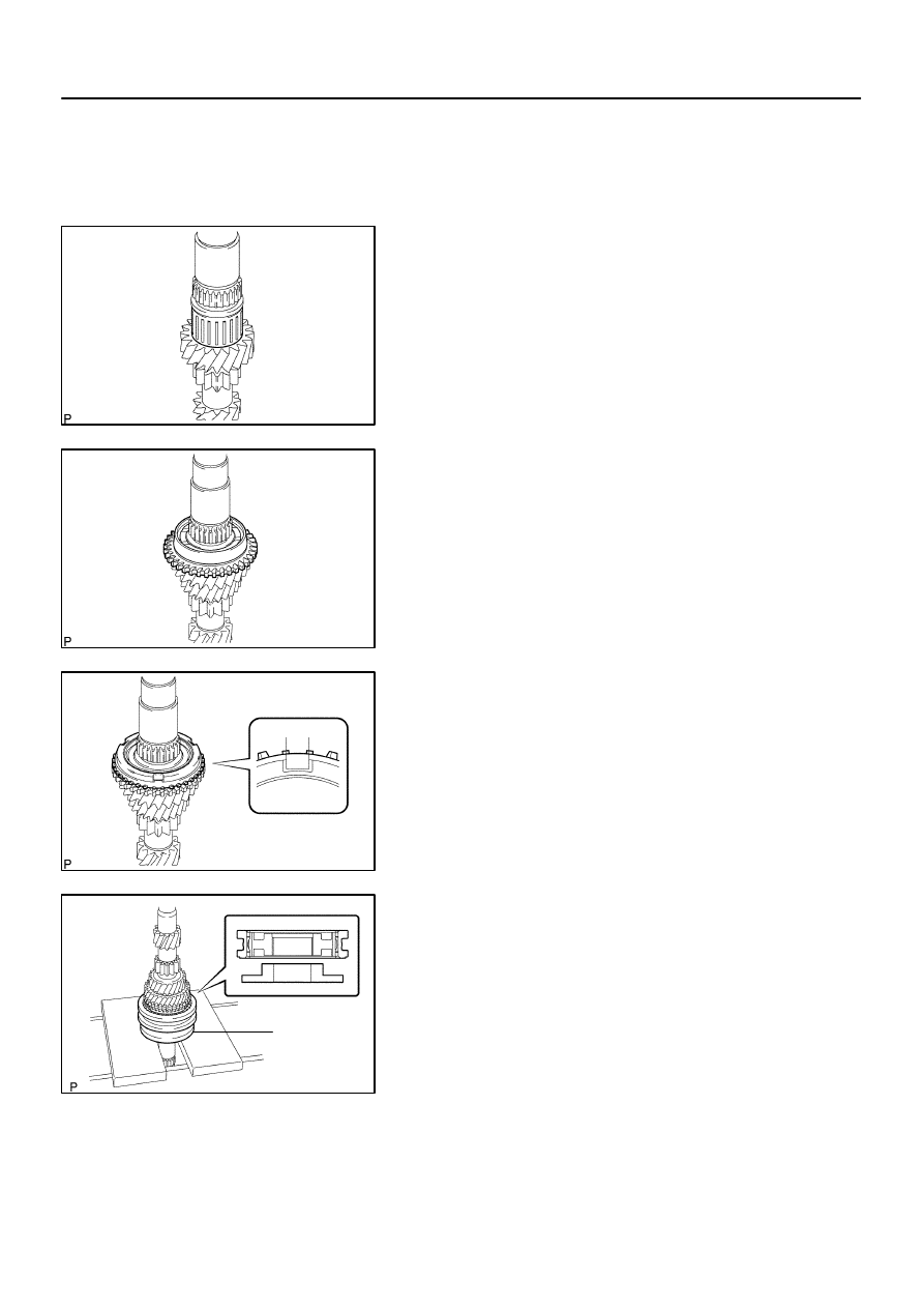
C67823
C67834
C80463
Key position
C80563
SST
–
MANUAL TRANSMISSION/TRANSAXLE
INPUT SHAFT ASSY (C59)
41–69
1469
Author:
Date:
2004 COROLLA (RM1037U)
(b)
Install the 2 synchromesh key springs with 3 synchro-
mesh shifting keys to the transmission clutch hub No.2.
HINT:
Do not set the both openings of the shifting key springs in the
same position.
19.
INSTALL 3RD GEAR NEEDLE ROLLER BEARING
(a)
Coat the 3rd gear needle roller bearing with gear oil,
install it to the input shaft.
20.
INSTALL 3RD GEAR
(a)
Coat the 3rd gear with gear oil, install it to the input shaft.
21.
INSTALL 3RD GEAR SYNCHRONIZER RING
(a)
Coat the 3rd gear synchronizer ring with gear oil, install
it to the 3rd gear.
22.
INSTALL TRANSMISSION CLUTCH HUB NO.2
(a)
Using SST and a press, install the transmission clutch
hub No.2 to the input shaft.
SST
09316–60011 (09316–00021)
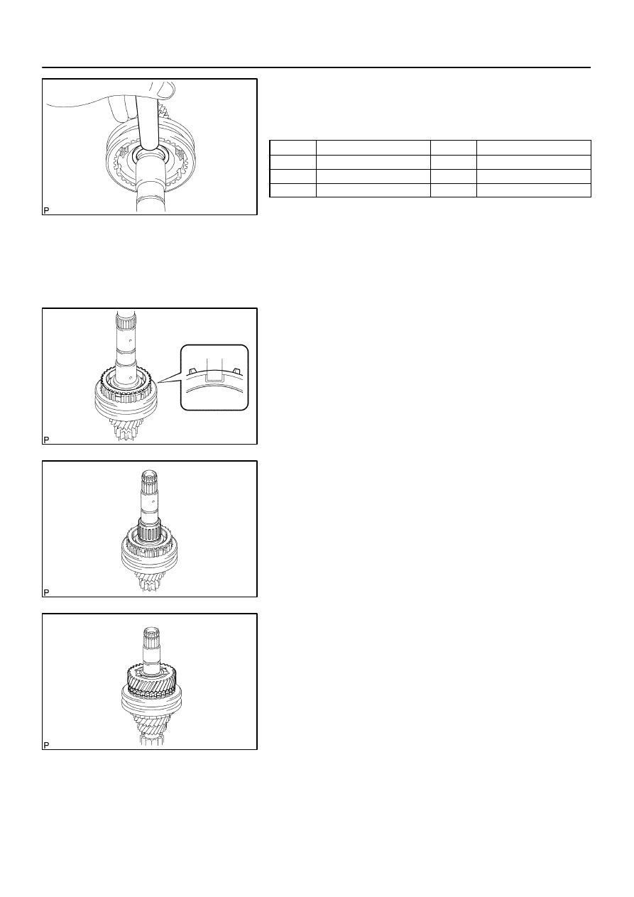
C67837
C80464
Key position
C80560
C80564
41–70
–
MANUAL TRANSMISSION/TRANSAXLE
INPUT SHAFT ASSY (C59)
1470
Author:
Date:
2004 COROLLA (RM1037U)
(b)
Select a snap ring from the table below that will make the
thrust clearance of the transmission clutch hub No.2 be-
low 0.1 mm (0.0039 in.).
Snap ring thickness:
Mark
Thickness: mm (in.)
Mark
Thickness: mm (in.)
0
2.30 (0.0906)
3
2.48 (0.0976)
1
2.36 (0.0929)
4
2.54 (0.1000)
2
2.42 (0.0953)
5
2.60 (0.1024)
(c)
Using a brass bar and a hammer, tap in the snap ring.
NOTICE:
Take care not to damage the journal surface of the input
shaft.
23.
INSTALL 4TH GEAR SYNCHRONIZER RING
(a)
Coat the 4th gear synchronizer ring with gear oil, install it
to the transmission clutch hub No.2.
24.
INSTALL 4TH GEAR NEEDLE ROLLER BEARING
(a)
Coat the 4th gear needle roller bearing and 4th gear bear-
ing spacer with gear oil, install them to the input shaft.
25.
INSTALL 4TH GEAR
(a)
Coat the 4th gear with gear oil, install it to the input shaft.
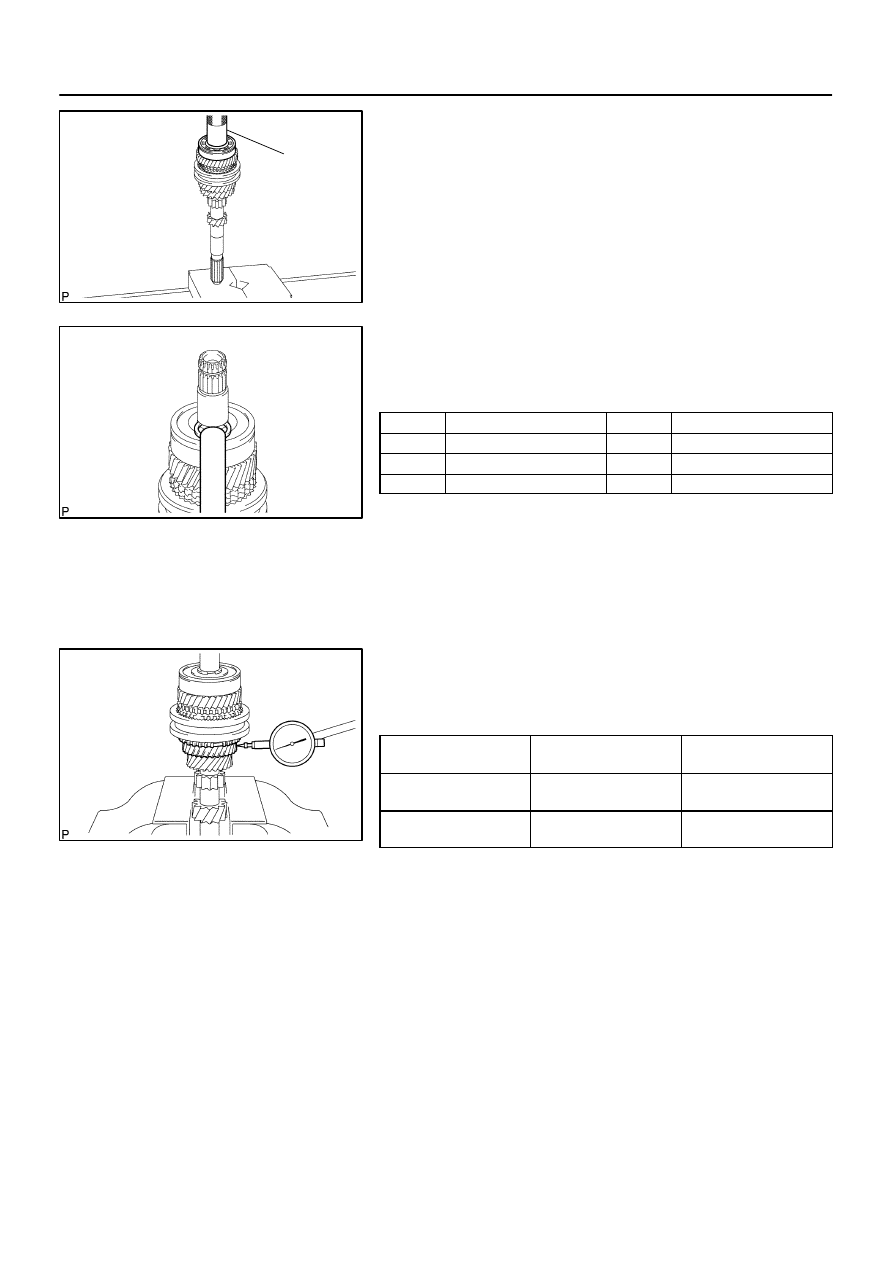
C80565
SST
C80566
C67815
–
MANUAL TRANSMISSION/TRANSAXLE
INPUT SHAFT ASSY (C59)
41–71
1471
Author:
Date:
2004 COROLLA (RM1037U)
26.
INSTALL INPUT SHAFT REAR RADIAL BALL
BEARING
(a)
Using SST and a press, install the input shaft rear radial
ball bearing to the input shaft.
SST
09636–20010
(b)
Select a snap ring from the table below that will make the
thrust clearance of the input shaft rear radial ball bearing
below 0.1 mm (0.0039 in.).
Snap ring thickness:
Mark
Thickness: mm (in.)
Mark
Thickness: mm (in.)
0
2.29 (0.0901)
3
2.47 (0.0972)
1
2.35 (0.0925)
4
2.53 (0.0996)
2
2.41 (0.0948)
5
2.59 (0.1019)
(c)
Using a brass bar and a hammer, tap in the snap ring.
NOTICE:
Take care not to damage the journal surface of the snap
ring.
27.
INSPECT 3RD GEAR RADIAL CLEARANCE
(a)
Using a dial indicator, measure the 3rd gear radial clear-
ance.
3rd gear radial clearance:
Standard clearance:
mm (in.)
Maximum clearance:
mm (in.)
KOYO made
0.015 – 0.058
(0.0006 – 0.0023)
0.058 (0.0023)
NSK made
0.015 – 0.056
(0.0006 – 0.0022)
0.056 (0.0022)
If the clearance exceeds the maximum, replace the gear,
needle roller bearing or shaft.
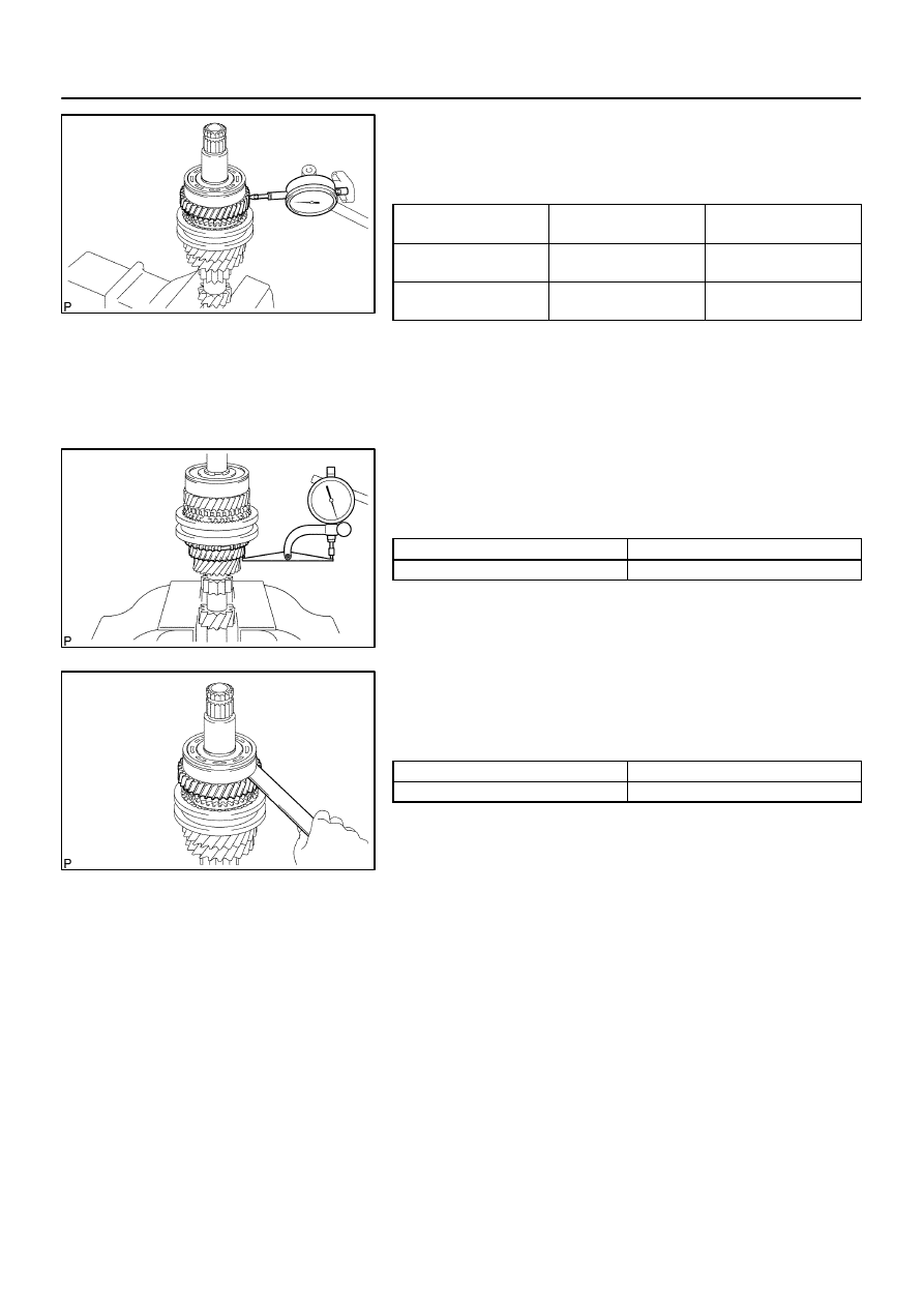
C80558
C67816
C80557
41–72
–
MANUAL TRANSMISSION/TRANSAXLE
INPUT SHAFT ASSY (C59)
1472
Author:
Date:
2004 COROLLA (RM1037U)
28.
INSPECT 4TH GEAR RADIAL CLEARANCE
(a)
Using a dial indicator, measure the 4th gear radial clear-
ance.
4th gear radial clearance:
Standard clearance:
mm (in.)
Maximum clearance:
mm (in.)
KOYO made
0.015 – 0.058
(0.0006 – 0.0023)
0.058 (0.0023)
NSK made
0.015 – 0.056
(0.0006 – 0.0022)
0.056 (0.0022)
If the clearance exceeds the maximum, replace the gear,
needle roller bearing or shaft.
29.
INSPECT 3RD GEAR THRUST CLEARANCE
(a)
Using a dial indicator, measure the 3rd gear thrust clear-
ance.
3rd gear thrust clearance:
Standard clearance: mm (in.)
Maximum clearance: mm (in.)
0.10 – 0.35 (0.0039 – 0.0138)
0.35 (0.0138)
30.
INSPECT 4TH GEAR THRUST CLEARANCE
(a)
Using a feeler gauge, measure the 4th gear thrust clear-
ance.
4th gear thrust clearance:
Standard clearance: mm (in.)
Maximum clearance: mm (in.)
0.10 – 0.55 (0.0039 – 0.0217)
0.55 (0.0217)
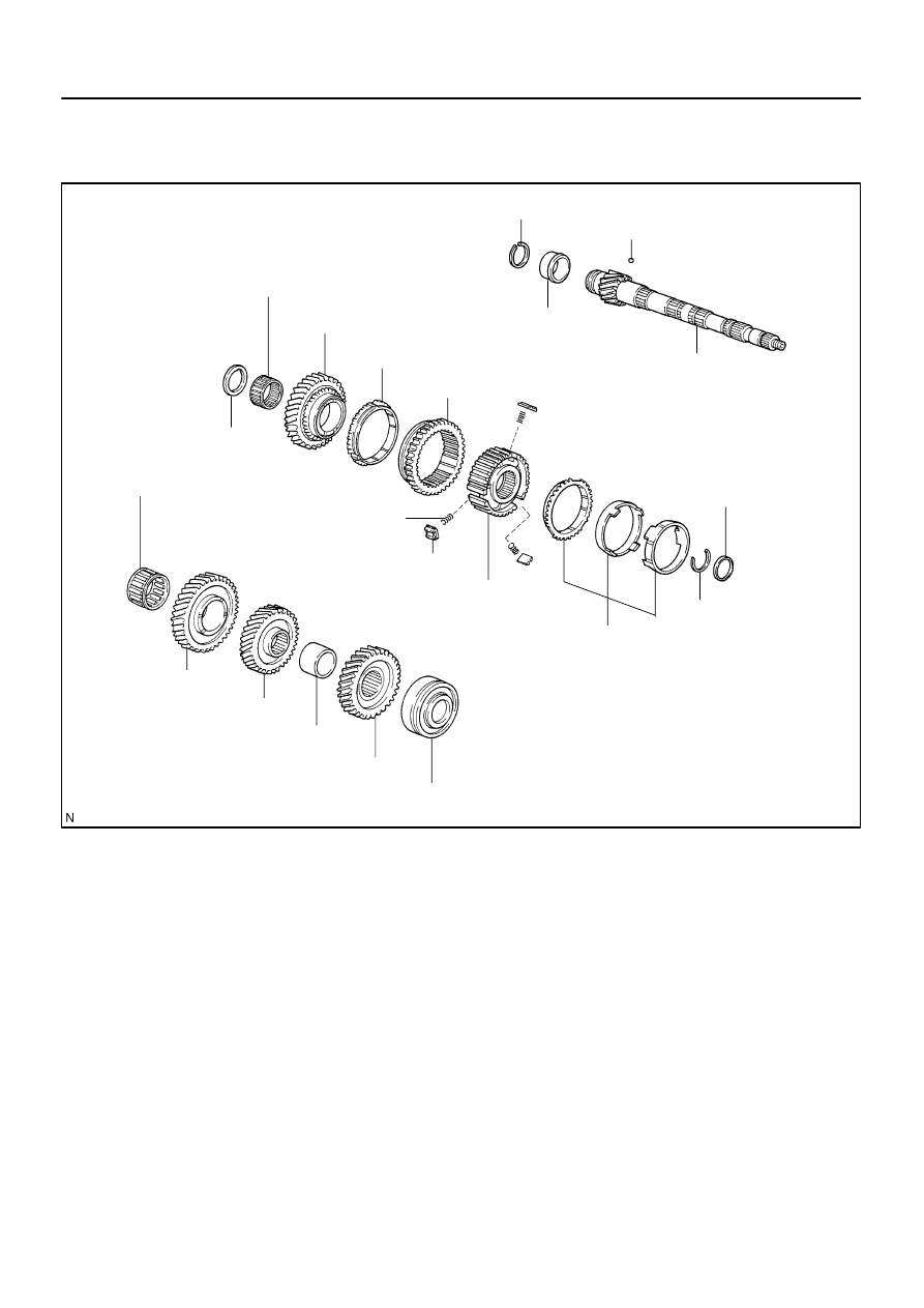
4107I–01
D07721
Snap Ring
1st Gear Thrust Washer Pin or Ball
Output Shaft
Output Shaft Front Bearing
1st Gear Needle Roller Bearing
1st Gear
Synchronizer Ring No.1
Reverse Gear
2nd Gear Bearing Spacer
Snap Ring
Synchronizer Ring Set No.2
Transmission Clutch Hub No.1
Synchromesh Shifting Key Spring
Synchromesh Shifting Key
1st Gear Thrust Washer
2nd Gear Needle Roller Bearing
2nd Gear
3rd Driven Gear
Output Gear Spacer
4th Driven Gear
Output Shaft Rear Bearing
Non–reusable part
–
MANUAL TRANSMISSION/TRANSAXLE
OUTPUT SHAFT ASSY (C59)
41–73
1473
Author:
Date:
2004 COROLLA (RM1037U)
OUTPUT SHAFT ASSY (C59)
COMPONENTS
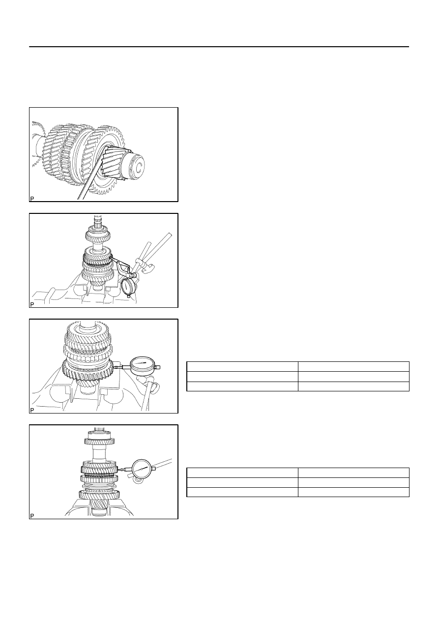
4107J–01
C68252
C68312
C68309
C68254
41–74
–
MANUAL TRANSMISSION/TRANSAXLE
OUTPUT SHAFT ASSY (C59)
1474
Author:
Date:
2004 COROLLA (RM1037U)
OVERHAUL
1.
INSPECT 1ST GEAR THRUST CLEARANCE
(a)
Using a feeler gauge, measure the 1st gear thrust clear-
ance.
Standard clearance:
0.10 – 0.40 mm (0.0039 – 0.0157 in.)
2.
INSPECT 2ND GEAR THRUST CLEARANCE
(a)
Using a dial indicator, measure the 2nd gear thrust clear-
ance.
Standard clearance:
0.10 – 0.45 mm (0.0039 – 0.0177 in.)
3.
INSPECT 1ST GEAR RADIAL CLEARANCE
(a)
Using a dial indicator, measure the 1st gear radial clear-
ance.
Standard clearance:
Bearing
Clearance: mm (in.)
KOYO made
0.015 – 0.058 (0.0006 – 0.0023)
NSK made
0.015 – 0.056 (0.0006 – 0.0022)
If the clearance is out of specification, replace the 1st gear
needle roller bearing.
4.
INSPECT 2ND GEAR RADIAL CLEARANCE
(a)
Using a dial indicator, measure the 2nd gear radial clear-
ance.
Standard clearance:
Bearing
Clearance: mm (in.)
KOYO made
0.015 – 0.058 (0.0006 – 0.0023)
NSK made
0.015 – 0.056 (0.0006 – 0.0022)
If the clearance is out of specification, replace the 2nd gear
needle roller bearing.
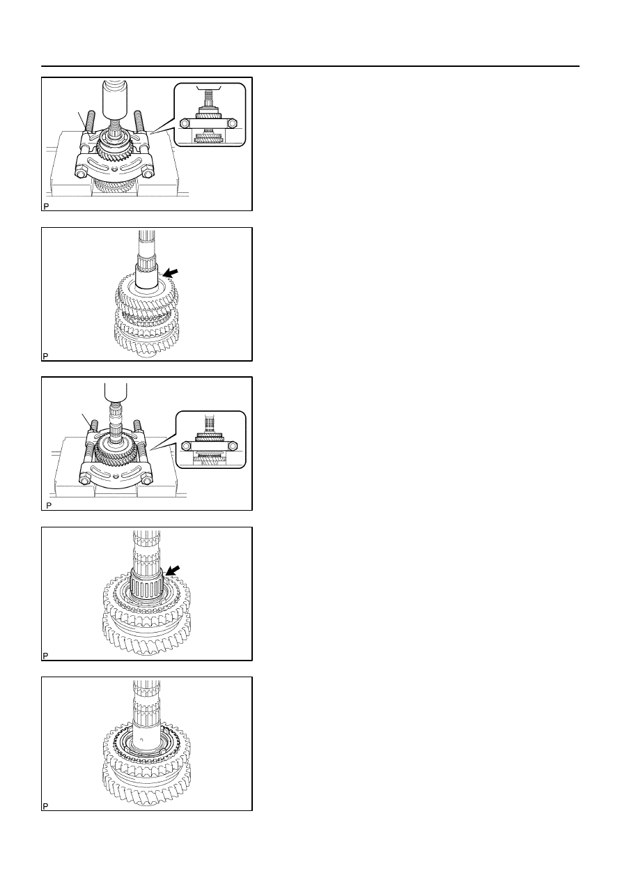
C80539
SST
C68005
C80540
SST
C68008
C68010
–
MANUAL TRANSMISSION/TRANSAXLE
OUTPUT SHAFT ASSY (C59)
41–75
1475
Author:
Date:
2004 COROLLA (RM1037U)
5.
REMOVE 4TH DRIVEN GEAR
(a)
Using SST and a press, remove the output shaft
rear
bearing with 4th driven gear from the output shaft.
SST
09950–00020
6.
REMOVE OUTPUT GEAR SPACER
(a)
Remove the output gear spacer from the output shaft.
7.
REMOVE 2ND GEAR
(a)
Using SST and a press, remove the 3rd driven gear with
2nd gear from the output shaft.
SST
09950–00020
8.
REMOVE 2ND GEAR NEEDLE ROLLER BEARING
(a)
Remove the 2nd gear needle roller bearing from the out-
put shaft.
9.
REMOVE SYNCHRONIZER RING SET NO.2
(a)
Remove the synchronizer ring set No.2 from the output
shaft.
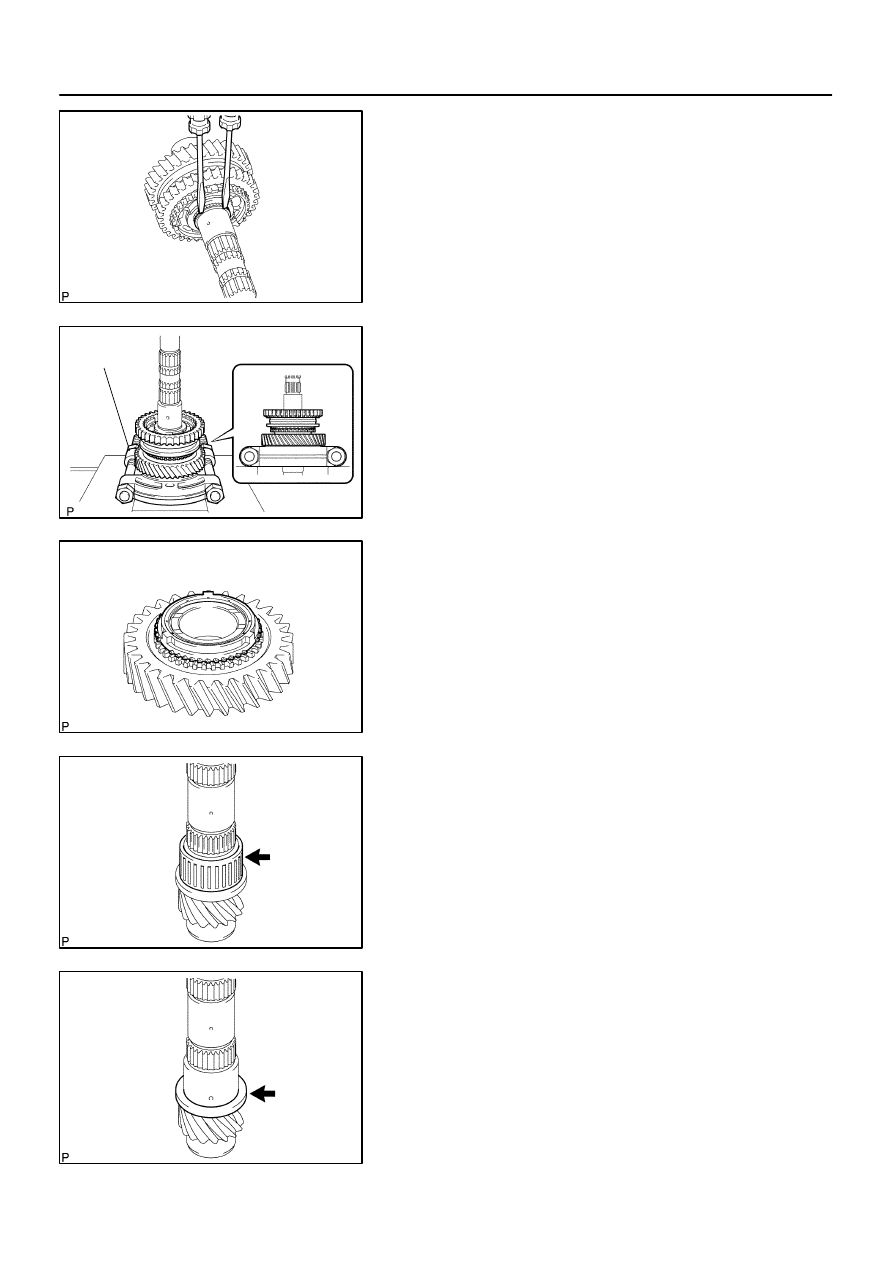
C68011
C94308
SST
C68516
C68012
C68013
41–76
–
MANUAL TRANSMISSION/TRANSAXLE
OUTPUT SHAFT ASSY (C59)
1476
Author:
Date:
2004 COROLLA (RM1037U)
10.
REMOVE 1ST GEAR
(a)
Using 2 screwdrivers and a hammer, tap out the snap
ring.
HINT:
Using a waste to prevent the snap ring from being scattered.
(b)
Using SST and a press, remove the transmission clutch
hub No.1 with 1st gear from the output shaft.
SST
09950–00020
NOTICE:
Do not tighten SST excessively.
Support the input shaft by hand so that it will not be
dropped off.
11.
REMOVE SYNCHRONIZER RING NO.1
(a)
Remove the synchronizer ring No.1 from the 1st gear.
12.
REMOVE 1ST GEAR NEEDLE ROLLER BEARING
(a)
Remove the 1st gear needle roller bearing from the output
shaft.
13.
REMOVE 1ST GEAR THRUST WASHER
(a)
Remove the 1st gear thrust washer from the output shaft.
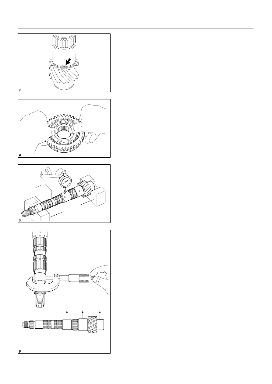
C68014
C68015
C80545
V–block
A
B
C
C80439
–
MANUAL TRANSMISSION/TRANSAXLE
OUTPUT SHAFT ASSY (C59)
41–77
1477
Author:
Date:
2004 COROLLA (RM1037U)
14.
REMOVE 1ST GEAR THRUST WASHER PIN OR BALL
(a)
Remove the 1st gear thrust washer pin or ball from the
output shaft.
15.
REMOVE REVERSE GEAR
(a)
Remove the 3 synchromesh shifting keys, 3 synchro-
mesh shifting key springs and reverse gear.
NOTICE:
Using a waste to prevent the synchromesh shifting key and
spring from being scattered.
16.
INSPECT OUTPUT SHAFT
(a)
Using a dial indicator and 2 V–blocks, measure the shaft
runout.
Maximum runout: 0.015 mm (0.0006 in.)
If the runout exceeds the maximum, replace the output shaft.
(b)
Using a micrometer, measure the outer diameter of the
output shaft journal surface.
Outer diameter:
Part A: 31.985 mm (1.2592 in.)
Part B: 37.985 mm (1.4955 in)
Part C: 32.985 mm (1.2986 in)
If the outer diameter is below the minimum, replace the output
shaft.
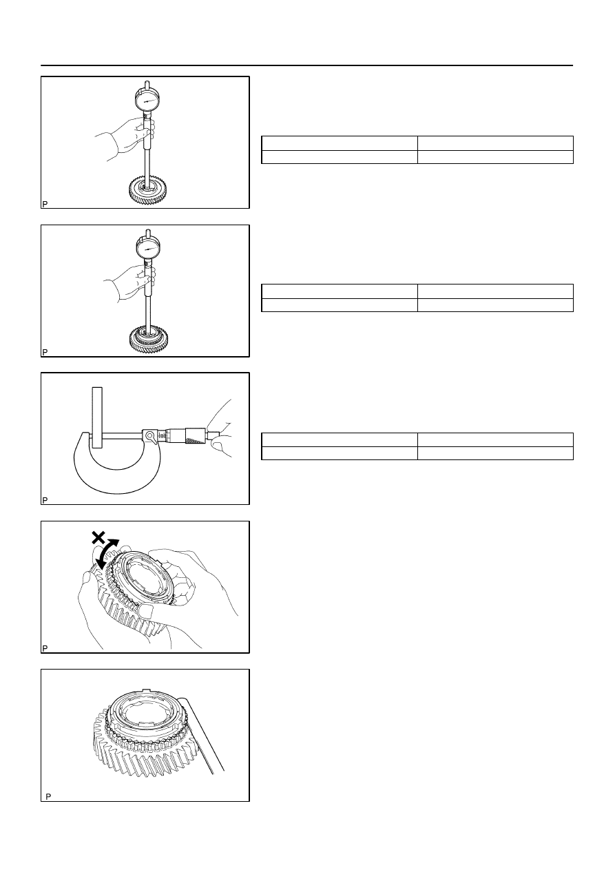
C68018
C68017
C68514
C68023
C68239
41–78
–
MANUAL TRANSMISSION/TRANSAXLE
OUTPUT SHAFT ASSY (C59)
1478
Author:
Date:
2004 COROLLA (RM1037U)
17.
INSPECT 2ND GEAR
(a)
Using a cylinder gauge, measure the inside diameter of
the 2nd gear.
Inside diameter:
New gear: mm (in.)
Maximum inside diameter: mm (in.)
38.015 – 38.031 (1.4967 – 1.4973)
38.031 (1.4973)
If the inside diameter exceeds the maximum, replace the 2nd
gear.
18.
INSPECT 1ST GEAR
(a)
Using a cylinder gauge, measure the inside diameter of
the 1st gear.
Inside diameter:
New gear: mm (in.)
Maximum inside diameter: mm (in.)
44.015 – 44.031 (1.7329 – 1.7335)
44.031 (1.7335)
If the inside diameter exceeds the maximum, replace the 1st
gear.
19.
INSPECT 1ST GEAR THRUST WASHER
(a)
Using a micrometer, measure the thickness of 1st gear
thrust washer.
Thickness:
New thrust washer: mm (in.)
Minimum thickness: mm (in.)
5.975 – 6.025 (0.2352 – 0.2372)
5.9755 (0.2352)
If the thickness is below the minimum, replace the 1st gear
thrust washer.
20.
INSPECT SYNCHRONIZER RING SET NO.2
(a)
Coat the 2nd gear cone with gear oil.
Check the braking effect of the synchronizer ring set No.2.
(b)
Using a feeler gauge, measure the clearance between
the synchronizer ring back and gear spline end.
Standard clearance: 0.7 – 1.3 mm (0.0276 – 0.0512 in.)
If the clearance is out of specification, replace the synchronizer
ring set No.2.
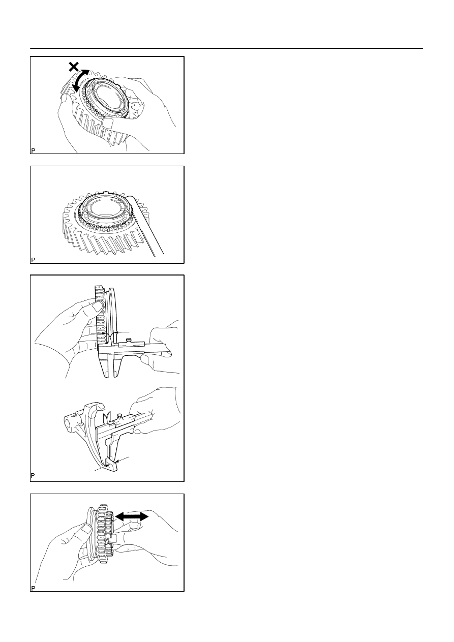
C68021
C68022
C68409
A
B
Clearance = (A – B)
C68240
–
MANUAL TRANSMISSION/TRANSAXLE
OUTPUT SHAFT ASSY (C59)
41–79
1479
Author:
Date:
2004 COROLLA (RM1037U)
21.
INSPECT SYNCHRONIZER RING NO.1
(a)
Coat the 1st gear cone with gear oil.
Check the braking effect of the synchronizer ring No.1.
(b)
Using a feeler gauge, measure the clearance between
the synchronizer ring back and gear spline end.
Standard clearance:
0.75 – 1.65 mm (0.0295 – 0.065 in.)
If the clearance is out of specification, replace the synchronizer
ring No.1.
22.
INSPECT REVERSE GEAR
(a)
Using a vernier caliper gauge, measure the clearance be-
tween reverse gear and shift fork.
Standard clearance:
0.15 – 0.35 mm (0.0059 – 0.0138 in.)
If the clearance is out of specification, replace the reverse gear
and reverse shift fork.
23.
INSPECT TRANSMISSION CLUTCH HUB NO.1
(a)
Check that the transmission clutch hub No.1 and reverse
gear sub–assy slides smoothly.
(b)
Check that the spline gear’s edges of the reverse gear
sub–assy is not worn down.
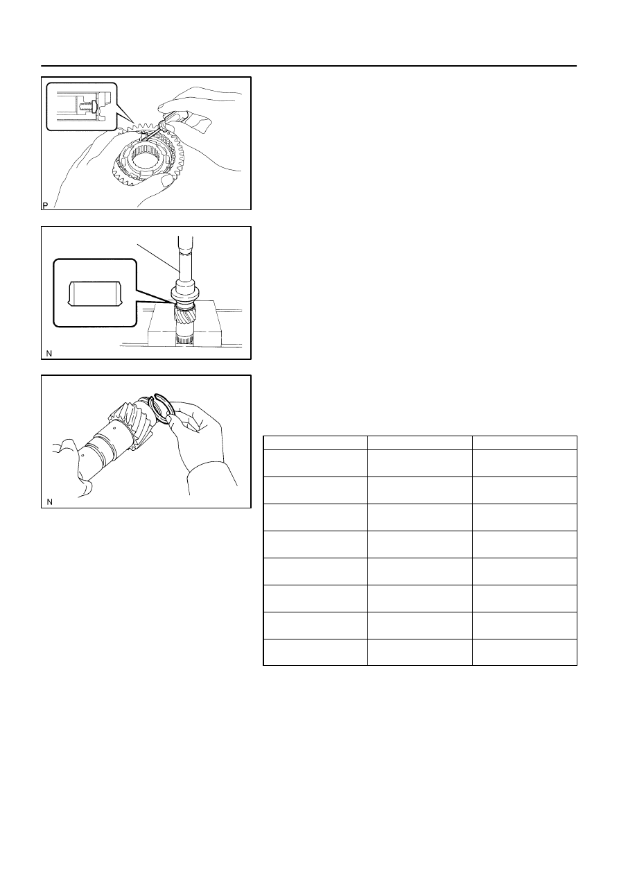
C68241
D08263
SST
C95325
41–80
–
MANUAL TRANSMISSION/TRANSAXLE
OUTPUT SHAFT ASSY (C59)
1480
Author:
Date:
2004 COROLLA (RM1037U)
24.
INSTALL REVERSE GEAR
(a)
Coat the reverse gear with gear oil, install it to the trans-
mission clutch hub No.1.
NOTICE:
Be sure to set the reverse gear and transmission clutch
hub No.1 in incorrect orientation.
(b)
Using a screwdriver, install the 3 synchromesh shifting
key springs and 3 synchromesh shifting keys.
25.
INSTALL OUTPUT SHAFT FRONT BEARING
(a)
Using SST and a press, install the output shaft front bear-
ing (inner race) to the output shaft.
SST
09223–50010
(b)
Select a snap ring from the table below that will make the
thrust clearance of the output shaft front bearing (inner
race) below 0.1 mm (0.0039 in.).
Snap ring thickness:
Part No.
Thickness: mm (in.)
Mark
90520 – 30032
1.85 – 1.90
(0.0728 – 0.0748)
7
90520 – 30033
1.90 – 1.95
(0.0748 – 0.0768)
8
90520 – 30002
1.95 – 2.00
(0.0768 – 0.0787)
1
90520 – 30003
2.00 – 2.05
(0.0787 – 0.0807)
2
90520 – 30004
2.05 – 2.10
(0.0807 – 0.0827)
3
90520 – 30005
2.10 – 2.15
(0.0827 – 0.0846)
4
90520 – 30006
2.15 – 2.20
(0.0846 – 0.0866)
5
90520 – 30007
2.20 – 2.25
(0.0866 – 0.0886)
6
(c)
Using a brass bar and a hammer, tap in the snap ring.
NOTICE:
Take care not to damage the journal surface of the output
shaft.
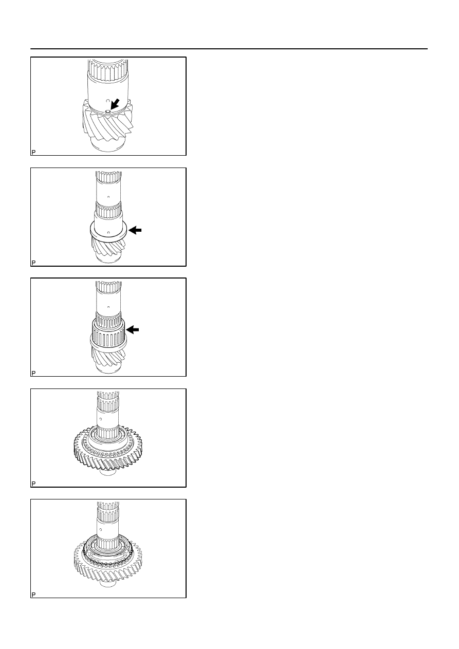
C68014
C68013
C68012
C68310
C68311
–
MANUAL TRANSMISSION/TRANSAXLE
OUTPUT SHAFT ASSY (C59)
41–81
1481
Author:
Date:
2004 COROLLA (RM1037U)
26.
INSTALL 1ST GEAR THRUST WASHER PIN OR BALL
(a)
Coat the 1st gear thrust washer pin or ball with MP
grease, install it to the output shaft.
27.
INSTALL 1ST GEAR THRUST WASHER
(a)
Coat the 1st gear thrust washer with gear oil, install it to
the output shaft.
28.
INSTALL 1ST GEAR NEEDLE ROLLER BEARING
(a)
Coat the 1st gear needle roller bearing with gear oil, install
it to the output shaft.
29.
INSTALL 1ST GEAR
(a)
Coat the 1st gear with gear oil, install it to the output shaft.
30.
INSTALL SYNCHRONIZER RING NO.1
(a)
Coat the synchronizer ring No.1 with gear oil, install it to
the 1st gear.
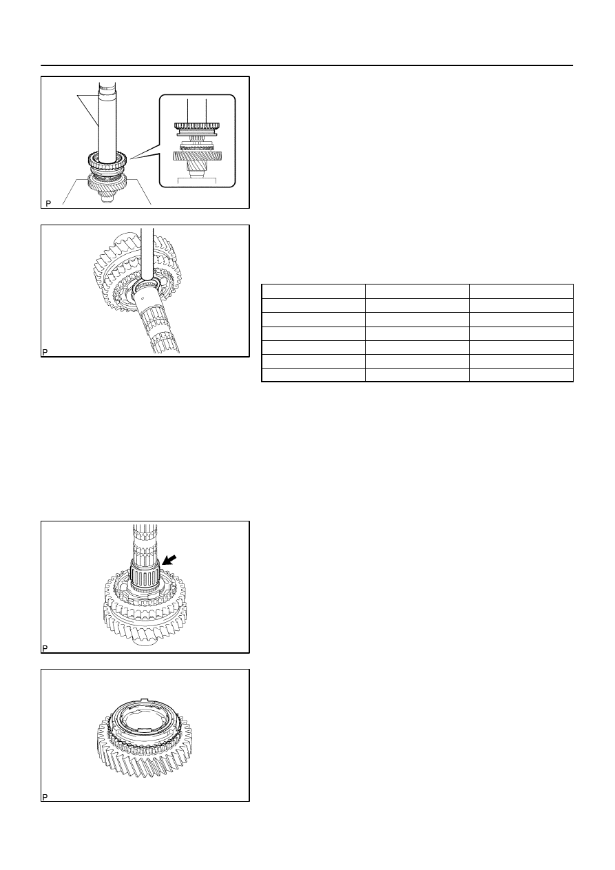
C94309
SST
C68244
C68246
C68247
41–82
–
MANUAL TRANSMISSION/TRANSAXLE
OUTPUT SHAFT ASSY (C59)
1482
Author:
Date:
2004 COROLLA (RM1037U)
31.
INSTALL TRANSMISSION CLUTCH HUB NO.1
(a)
Using SST and a press, install the transmission clutch
hub No.1 to the output shaft.
SST
09316–60011 (09316–00031)
NOTICE:
The 1st gear can be turned.
(b)
Select a snap ring from the table below that will make the
thrust clearance of the transmission clutch hub No.1 be-
low 0.1 mm (0.0039 in.).
Snap ring thickness:
Part No.
Thickness: mm (in.)
Mark
90520 – 29018
2.50 (0.0984)
A
90520 – 29019
2.56 (0.1008)
B
90520 – 29020
2.62 (0.1031)
C
90520 – 29021
2.68 (0.1055)
D
90520 – 29022
2.74 (0.1079)
E
90520 – 29023
2.80 (0.1102)
F
(c)
Using a brass bar and a hammer, install the snap ring to
the output shaft.
NOTICE:
Take care not to damage the journal surface of the output
shaft.
32.
INSTALL 2ND GEAR NEEDLE ROLLER BEARING
(a)
Coat the 2nd gear needle roller bearing with gear oil,
install it to the output shaft.
33.
INSTALL SYNCHRONIZER RING SET NO.2
(a)
Coat the synchronizer ring set No.2 with gear oil, install
it to the 2nd gear.
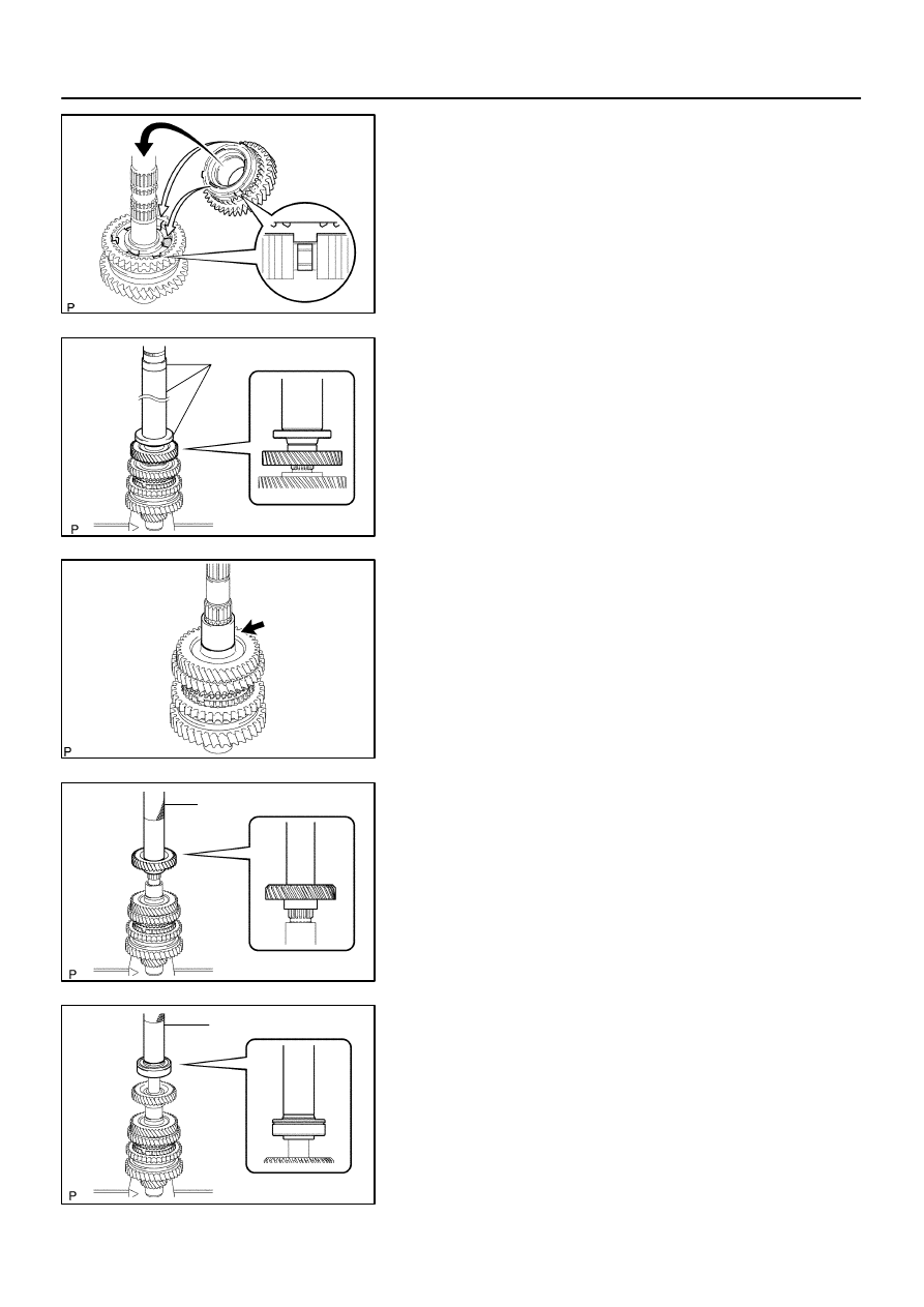
C95326
C94310
SST
C68005
C94311
SST
C94312
SST
–
MANUAL TRANSMISSION/TRANSAXLE
OUTPUT SHAFT ASSY (C59)
41–83
1483
Author:
Date:
2004 COROLLA (RM1037U)
34.
INSTALL 2ND GEAR
(a)
Coat the 2nd gear with gear oil, install it to the output
shaft.
NOTICE:
Fit the synchronizer inner ring claws into the slots in the
transmission clutch hub No.1.
35.
INSTALL 3RD DRIVEN GEAR
(a)
Using SST and a press, install the 3rd driven gear to the
output shaft.
SST
09309–36100 (09309–03610), 09608–00071,
09950–60010 (09951–00450)
36.
INSTALL OUTPUT GEAR SPACER
(a)
Install the output gear spacer to the output shaft.
37.
INSTALL 4TH DRIVEN GEAR
(a)
Using SST and a press, install 4th driven gear to the out-
put shaft.
SST
09612–22011
38.
INSTALL OUTPUT SHAFT REAR BEARING
(a)
Using SST and a press, install output shaft rear bearing
to the output shaft.
SST
09612–22011
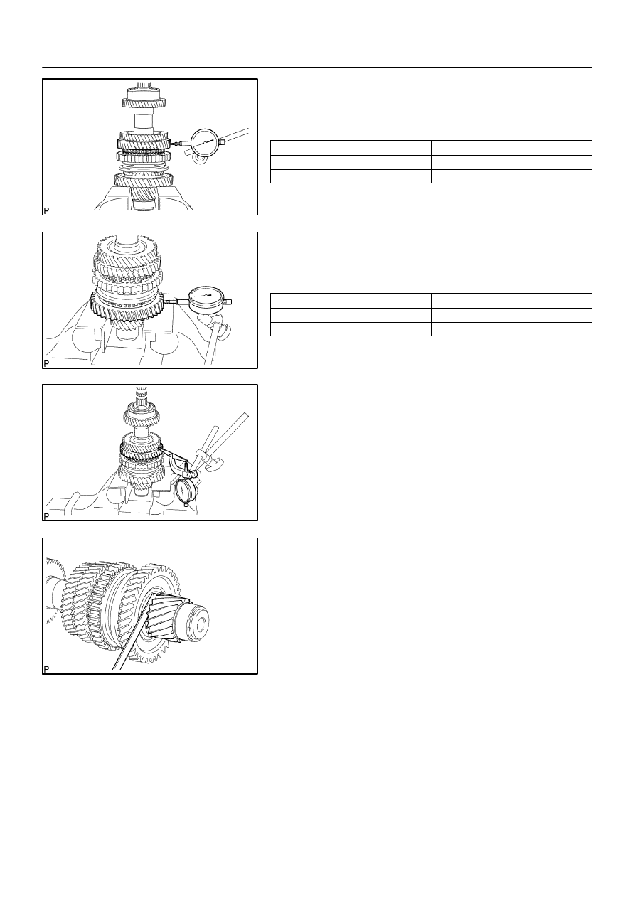
C68254
C68309
C68312
C68252
41–84
–
MANUAL TRANSMISSION/TRANSAXLE
OUTPUT SHAFT ASSY (C59)
1484
Author:
Date:
2004 COROLLA (RM1037U)
39.
INSPECT 2ND GEAR RADIAL CLEARANCE
(a)
Using a dial indicator, measure the 2nd gear radial clear-
ance.
Standard clearance:
Bearing
Clearance: mm (in.)
KOYO made
0.015 – 0.058 (0.0006 – 0.0023)
NSK made
0.015 – 0.056 (0.0006 – 0.0022)
If the clearance is out of specification, replace the 2nd gear
needle roller bearing.
40.
INSPECT 1ST GEAR RADIAL CLEARANCE
(a)
Using a dial indicator, measure the 1st gear radial clear-
ance.
Standard clearance:
Bearing
Clearance: mm (in.)
KOYO made
0.015 – 0.058 (0.0006 – 0.0023)
NSK made
0.015 – 0.056 (0.0006 – 0.0022)
If the clearance is out of specification, replace the 1st gear
needle roller bearing.
41.
INSPECT 2ND GEAR THRUST CLEARANCE
(a)
Using a dial indicator, measure the 2nd gear thrust clear-
ance.
Standard clearance:
0.10 – 0.45 mm (0.0039 – 0.0177 in.)
42.
INSPECT 1ST GEAR THRUST CLEARANCE
(a)
Using a feeler gauge, measure the 1st gear thrust clear-
ance.
Standard clearance:
0.10 – 0.40 mm (0.0039 – 0.0157 in.)
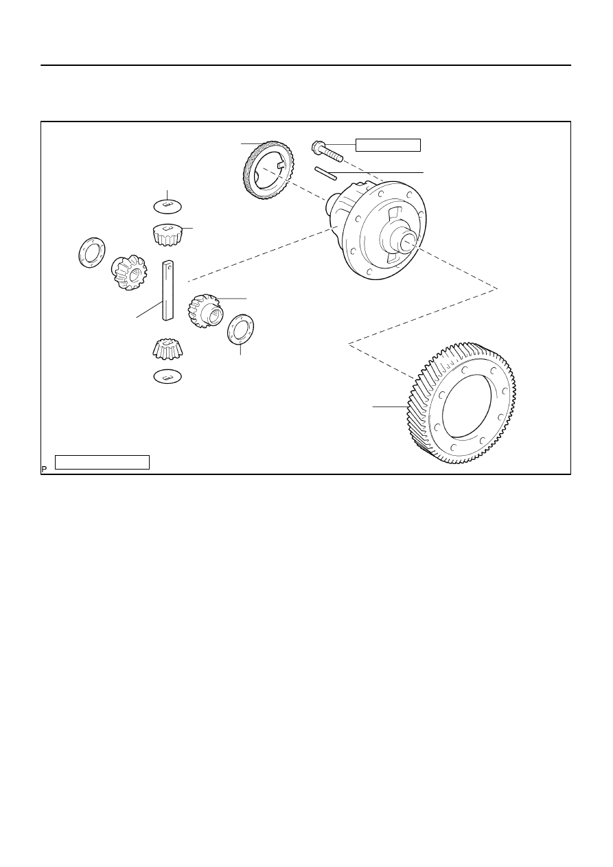
4107K–01
C95304
N
⋅
m (kgf
⋅
cm, ft
⋅
lbf)
: Specified torque
x 8
Front Differential
Pinion Shaft Straight Pin
Front Differential Pinion
Speedometer Drive
(MTM) Gear
Front Differential
Pinion Thrust Washer
Front Differential Side Gear
Front Differential Side Gear
Thrust Washer
Front Differential Ring Gear
Front Differential
Pinion Shaft No.1
77.4 (789, 57)
–
MANUAL TRANSMISSION/TRANSAXLE
DIFFERENTIAL CASE ASSY (C59)
41–85
1485
Author:
Date:
2004 COROLLA (RM1037U)
DIFFERENTIAL CASE ASSY (C59)
COMPONENTS
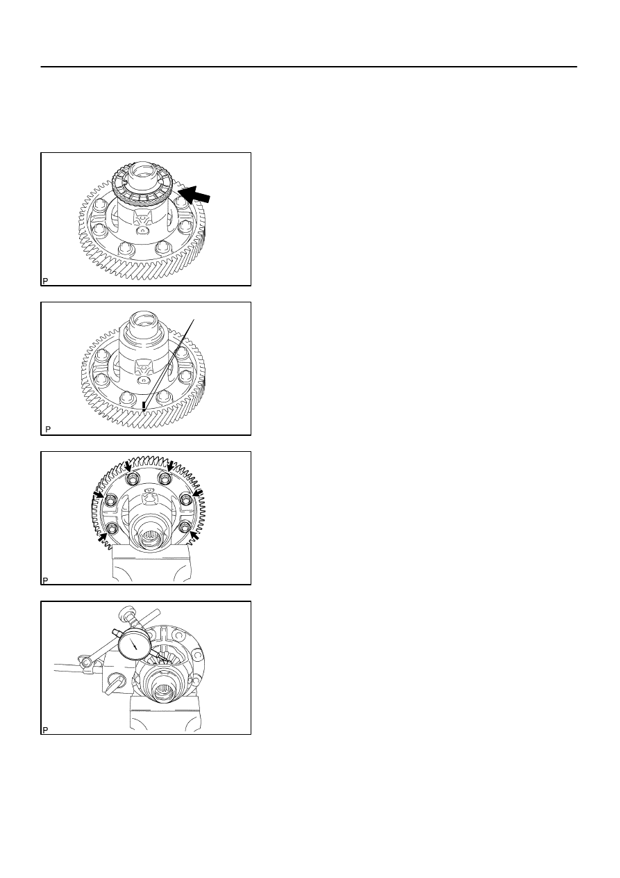
4107L–01
C67982
C94318
Matchmarks
C67984
C67989
41–86
–
MANUAL TRANSMISSION/TRANSAXLE
DIFFERENTIAL CASE ASSY (C59)
1486
Author:
Date:
2004 COROLLA (RM1037U)
OVERHAUL
1.
REMOVE SPEEDOMETER DRIVE (MTM) GEAR
(a)
Remove the speedometer drive (MTM) gear from the front
differential case.
2.
REMOVE FRONT DIFFERENTIAL RING GEAR
(a)
Place matchmarks on the front differential ring gear and
front differential case.
(b)
Remove the 8 bolts. Using a hammer, remove the front
differential ring gear.
3.
INSPECT FRONT DIFFERENTIAL SIDE GEAR
BACKLASH
(a)
Fixing the front differential pinion from the front differential
case side. Using a dial indicator, measure the backlash of
the front differential side gear.
Standard backlash:
0.05 – 0.20 mm (0.0020 – 0.0079 in.)
If the backlash is not within the specification, install the connect
side gear thrust washers.
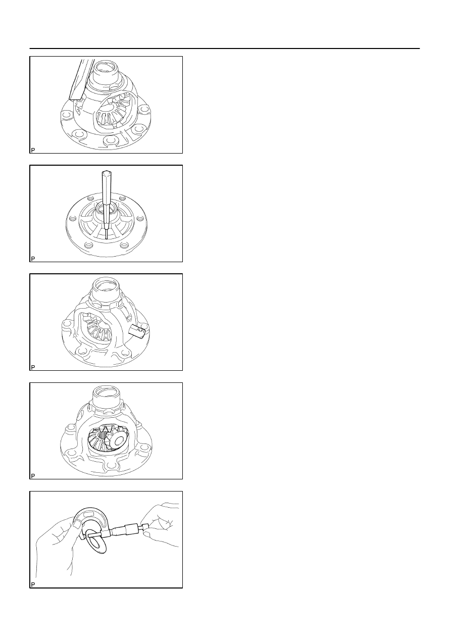
C67985
C80412
C80413
C80414
C80415
–
MANUAL TRANSMISSION/TRANSAXLE
DIFFERENTIAL CASE ASSY (C59)
41–87
1487
Author:
Date:
2004 COROLLA (RM1037U)
4.
REMOVE FRONT DIFFERENTIAL PINION SHAFT
STRAIGHT PIN
(a)
Using a chisel and a hammer, loosen the staked part of
the front differential case.
(b)
Using a pin punch (
φ
3 mm) and a hammer, remove the
front differential pinion shaft straight pin from the front dif-
ferential case.
5.
REMOVE FRONT DIFFERENTIAL PINION SHAFT
NO.1
(a)
Remove the front differential pinion shaft No.1 from the
front differential case.
6.
REMOVE FRONT DIFFERENTIAL SIDE GEAR
(a)
Remove the 2 front differential pinions, 2 front differential
pinion thrust washers, 2 front differential side gear thrust
washers and 2 front differential side gears from the front
differential case.
HINT:
Turning the front differential pinion, remove the 2 pinions and
side gear.
7.
INSPECT FRONT DIFFERENTIAL PINION THRUST
WASHER
(a)
Using a micrometer, measure the thickness of the front
differential pinion thrust washer.
Minimum thickness: 0.92 mm (0.0362 in.)
If the clearance is below the minimum, replace the front differ-
ential pinion thrust washer.
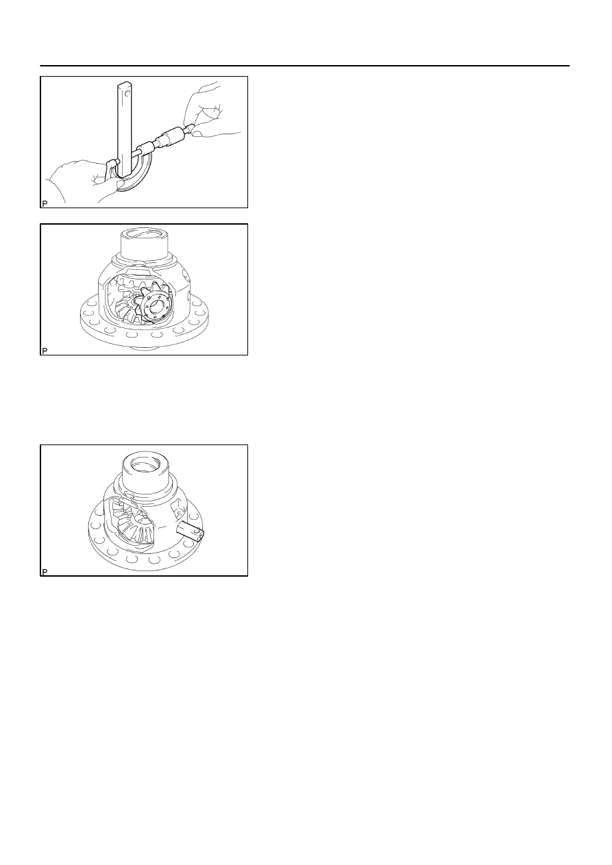
C68518
C83566
C83565
41–88
–
MANUAL TRANSMISSION/TRANSAXLE
DIFFERENTIAL CASE ASSY (C59)
1488
Author:
Date:
2004 COROLLA (RM1037U)
8.
INSPECT FRONT DIFFERENTIAL PINION SHAFT
NO.1
(a)
Using a micrometer, measure the the outer diameter of
the front differential pinion shaft No.1.
Minimum outer diameter: 16.982 mm (0.6686 in.)
If the outer diameter is less than the minimum, replace the front
differential pinion shaft No.1.
9.
INSTALL FRONT DIFFERENTIAL SIDE GEAR
(a)
Coat the sliding and rotating surface of the 2 front differ-
ential side gears with MP grease.
(b)
Install the 2 front differential side gear thrust washers to
the 2 front differential side gear.
HINT:
Install the front differential side gear thrust washer that has the
same thickness as the removed one.
(c)
Install the 2 front differential side gears, 2 front differential
pinions and 2 front differential side gear thrust washers to
the front differential case.
HINT:
Turning the front differential pinion, install the 2 front differential
pinions with front differential case.
10.
INSTALL FRONT DIFFERENTIAL PINION SHAFT NO.1
(a)
Coat the rotating surface of the front differential pinion
shaft No.1 with gear oil.
(b)
Install the front differential pinion shaft No.1 to the front
differential case so that the hole for the front differential
pinion shaft straight pin is aligned with the hole in the front
differential case.
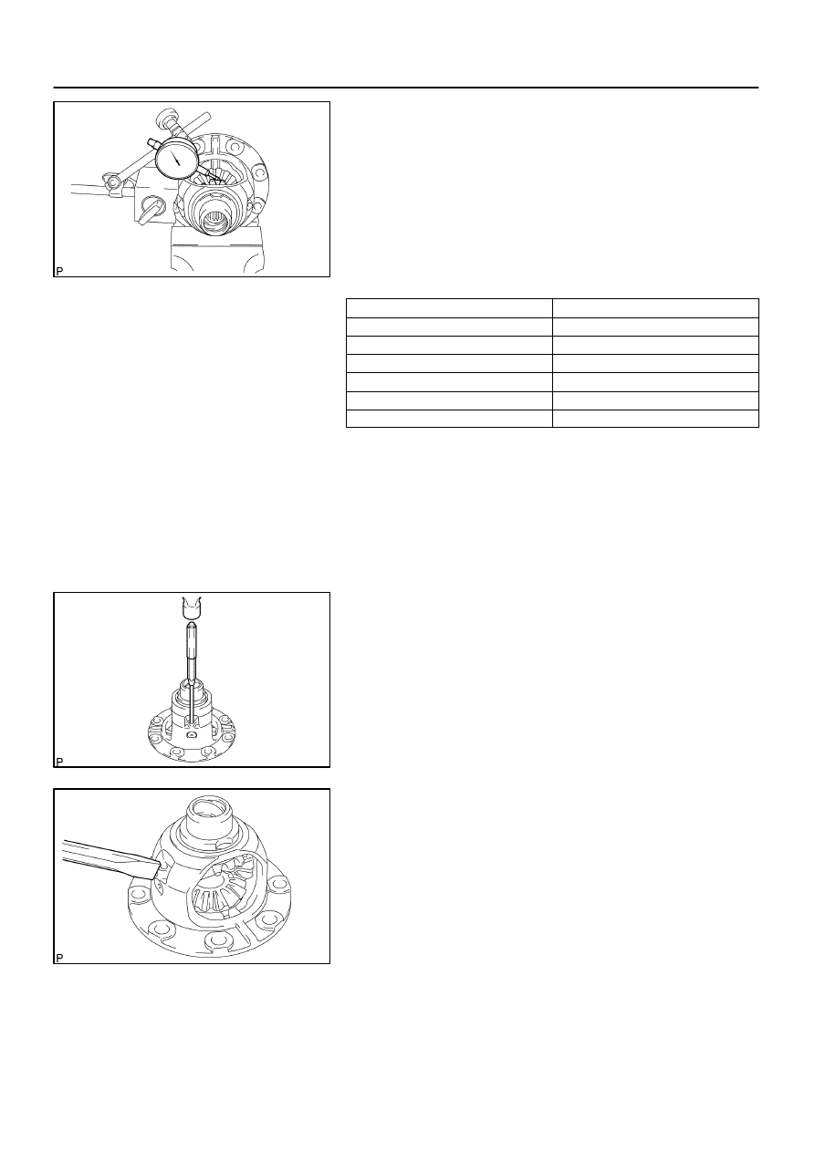
C67989
C67990
C67991
–
MANUAL TRANSMISSION/TRANSAXLE
DIFFERENTIAL CASE ASSY (C59)
41–89
1489
Author:
Date:
2004 COROLLA (RM1037U)
11.
ADJUST FRONT DIFFERENTIAL SIDE GEAR
BACKLASH
(a)
Fixing the front differential pinion to the front differential
case side. Using a dial indicator, measure the front differ-
ential side gear backlash.
Standard backlash:
0.05 – 0.20 mm (0.0020 – 0.0079 in.)
If the backlash is out of specification, replace the side gear
thrust washer.
Thrust washer thickness:
Part No.
Thickness: mm (in.)
41361 – 22140
0.95 (0.0374)
41361 – 22020
1.00 (0.0394)
41361 – 22150
1.05 (0.0413)
41361 – 22030
1.10 (0.0433)
41361 – 22160
1.15 (0.0453)
41361 – 22040
1.20 (0.0472)
HINT:
S
Because the thrust washer does not have any identifica-
tion mark, measure the front thickness with a micrometer
to select a proper thrust washer.
S
Select washers that has the same thickness as both the
right and left.
12.
INSTALL FRONT DIFFERENTIAL PINION SHAFT
STRAIGHT PIN
(a)
Using a pin punch (
φ
3 mm) and a hammer, install the front
differential pinion shaft straight pin to the front differential
case.
(b)
Using a chisel and a hammer, stake the front case hole.
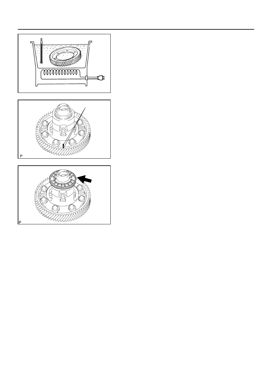
C94319
90 – 110
_
C (194.0 – 230.0
_
F)
C94318
Matchmarks
C67982
41–90
–
MANUAL TRANSMISSION/TRANSAXLE
DIFFERENTIAL CASE ASSY (C59)
1490
Author:
Date:
2004 COROLLA (RM1037U)
13.
INSTALL FRONT DIFFERENTIAL RING GEAR
(a)
Using a heater, heat the front differential ring gear to 90
– 110
_
C (194.0 – 230.0
_
F)
(b)
Clean the contact surface of the front differential case.
(c)
Align the both matchmarks, quickly install the 8 bolts with
the front differential ring gear to the front differential case.
Torque: 77.4 N
⋅
m (789 kgf
⋅
cm, 57 ft
⋅
lbf)
14.
INSTALL SPEEDOMETER DRIVE (MTM) GEAR
(a)
Install the speedometer drive (MTM) gear to the front dif-
ferential case.
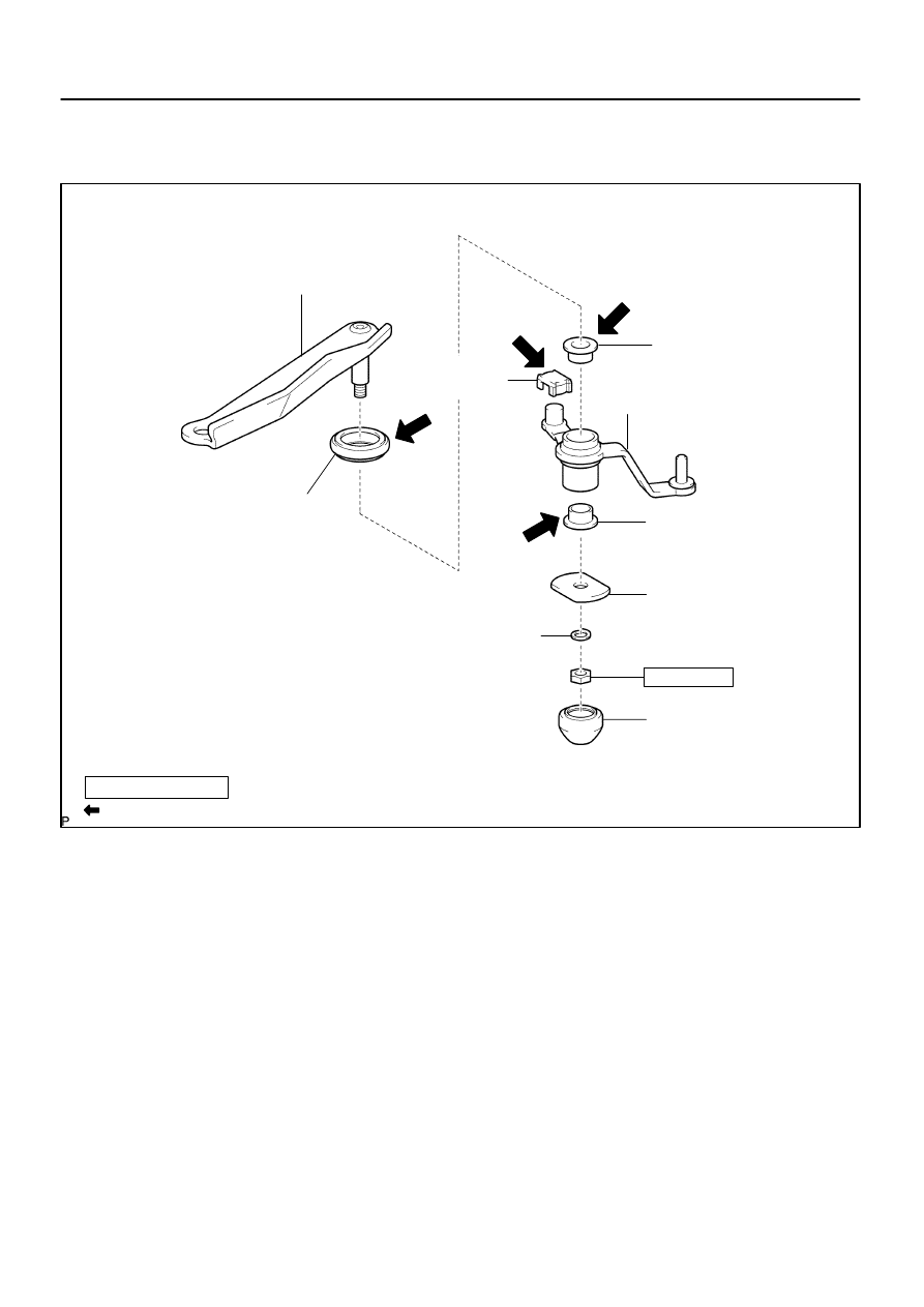
4107M–01
C94578
Apply MP grease
N
⋅
m (kgf
⋅
cm, ft
⋅
lbf)
: Specified torque
Control Shift
Lever Bush
Selecting Bellcrank
No.2 Bush
Selecting Bellcrank No.2
Selecting Bellcrank
No.2 Bush
Selecting Bellcrank
No.2 Plate Washer
Washer
Selecting Bellcrank
Dust Cover No.1
Selecting Bellcrank
Dust Cover No.2
Selecting Bellcrank Support
11.8 (120, 9)
–
MANUAL TRANSMISSION/TRANSAXLE
SHIFT & SELECT LEVER SHAFT ASSY (C59)
41–91
1491
Author:
Date:
2004 COROLLA (RM1037U)
SHIFT & SELECT LEVER SHAFT ASSY (C59)
COMPONENTS
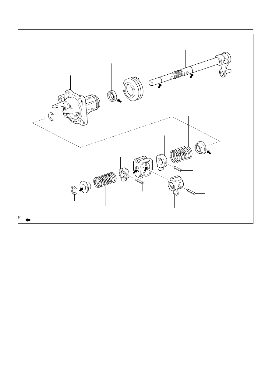
D12109
Snap Ring
Control Shaft Cover
Control Shaft Cover Oil Seal
Shift & Select Lever Shaft
Shift & Select Lever Shaft Boot
Compression Spring
Select Inner Lever
Shift Inter Lock Plate
Shift Lever Inner No.2
Select Spring Seat No.2
Apply MP grease
E–ring
Compression Spring
Slotted Spring Pin
Shift Inner Lever No.2
Slotted Spring Pin
Slotted Spring Pin
Non–reusable part
41–92
–
MANUAL TRANSMISSION/TRANSAXLE
SHIFT & SELECT LEVER SHAFT ASSY (C59)
1492
Author:
Date:
2004 COROLLA (RM1037U)
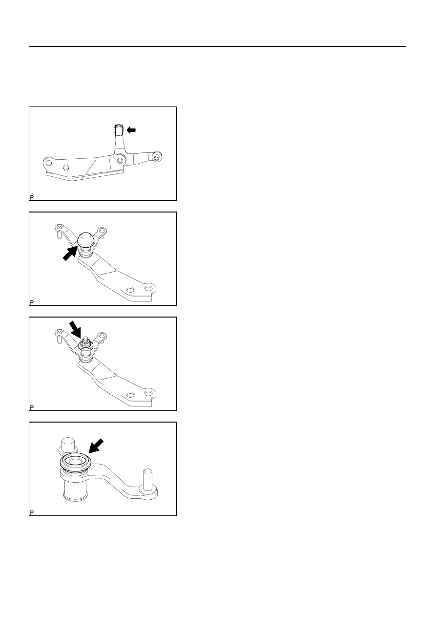
4107N–01
C80760
C80761
C80762
C80763
–
MANUAL TRANSMISSION/TRANSAXLE
SHIFT & SELECT LEVER SHAFT ASSY (C59)
41–93
1493
Author:
Date:
2004 COROLLA (RM1037U)
OVERHAUL
1.
REMOVE CONTROL SHIFT LEVER BUSH
(a)
Remove the control shift lever bush from the selecting
bellcrank assy.
2.
REMOVE SELECTING BELLCRANK DUST COVER
NO.1
(a)
Remove the selecting bellcrank dust cover No.1 from the
selecting bellcrank assy.
3.
REMOVE SELECTING BELL CRANK NO.2
(a)
Remove the nut, spring washer and selecting bellcrank
No.2 plate washer.
(b)
Remove the selecting bellcrank No.2 from the selecting
bellcrank support.
4.
REMOVE SELECTING BELLCRANK DUST COVER
NO.2
(a)
Remove the selecting bellcrank dust cover No.2 from the
selecting bellcrank No.2.
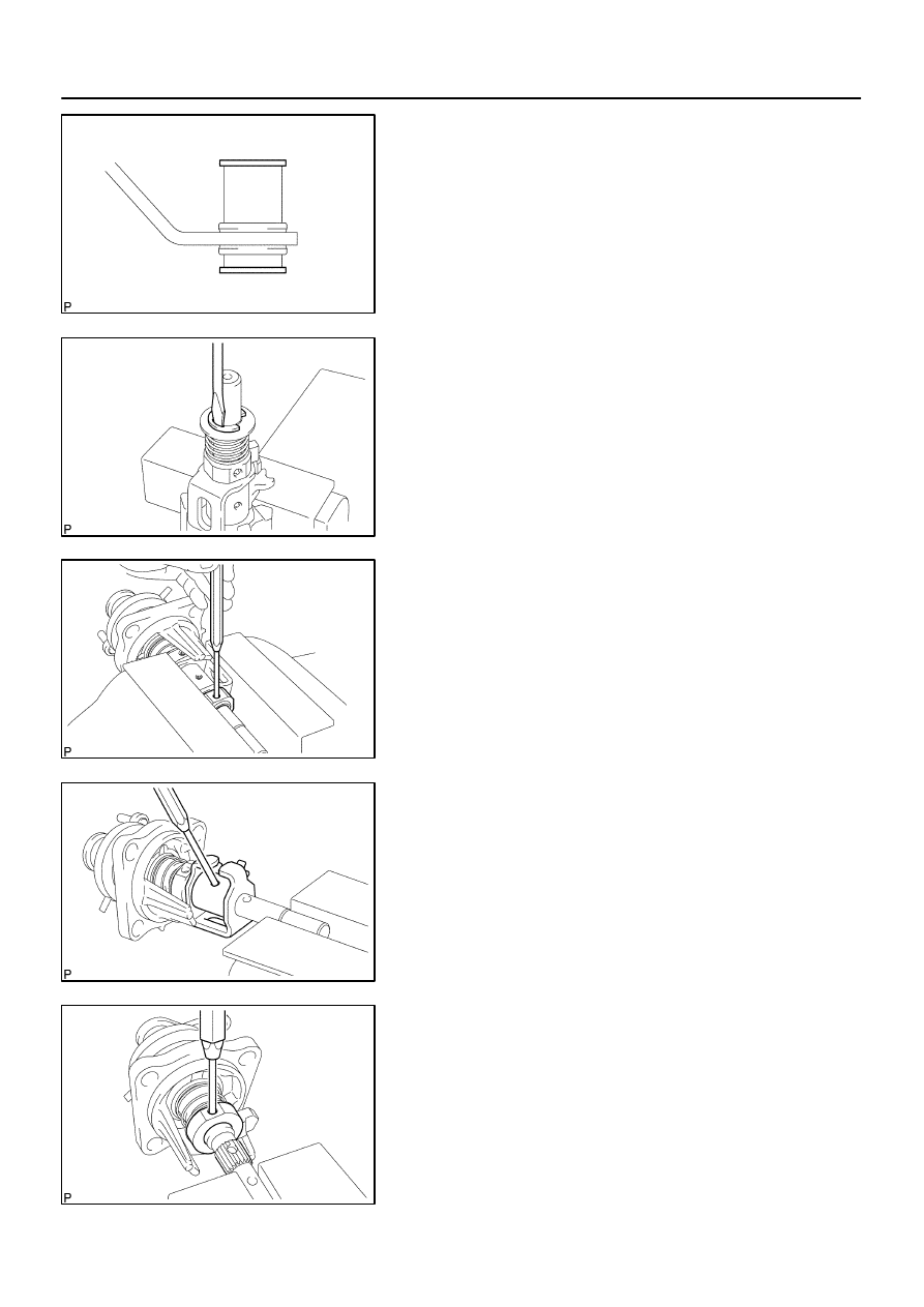
C80571
C80572
C80573
C80574
C80575
41–94
–
MANUAL TRANSMISSION/TRANSAXLE
SHIFT & SELECT LEVER SHAFT ASSY (C59)
1494
Author:
Date:
2004 COROLLA (RM1037U)
5.
REMOVE SELECTING BELLCRANK NO.2 BUSH
(a)
Remove the 2 selecting bellcrank No.2 bushes from the
selecting bellcrank No.2.
6.
REMOVE SELECT SPRING SEAT NO.2
(a)
Using a screwdriver, remove the E–ring, select spring
seat No.2 and select return spring No.2 from the shift &
select lever shaft.
7.
REMOVE SHIFT LEVER INNER NO.2
(a)
Using a pin punch (
φ
5 mm) and a hammer, remove the
slotted pin and shift lever inner No.2 from the shift & select
lever shaft.
HINT:
Make sure the orientation of the shift lever inner No.2.
8.
REMOVE SHIFT LEVER INNER NO.1
(a)
Using a pin punch (
φ
5 mm) and a hammer, remove the
slotted pin, shift lever inner No.1 and shift inter lock plate
from the shift & select lever shaft.
HINT:
Make sure the orientation of the shift lever inner No.1.
9.
REMOVE SELECT INNER LEVER
(a)
Using a pin punch (
φ
5 mm) and a hammer, remove the
slotted pin, select inner lever, select return spring No.1
and select return spring seat No.1.
HINT:
Make sure the orientation of the select inner lever.
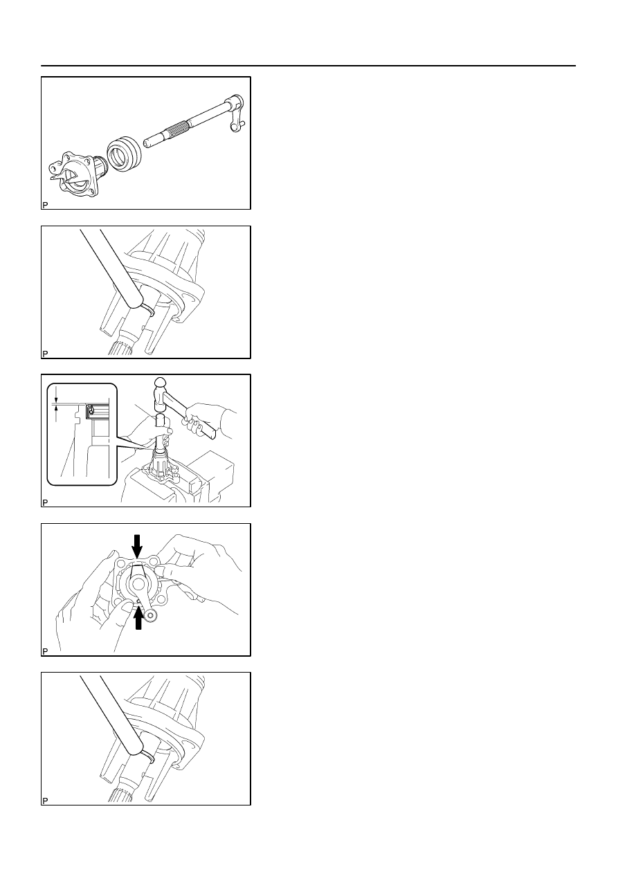
C95740
C95742
C94255
SST
C94256
C95742
–
MANUAL TRANSMISSION/TRANSAXLE
SHIFT & SELECT LEVER SHAFT ASSY (C59)
41–95
1495
Author:
Date:
2004 COROLLA (RM1037U)
10.
REMOVE CONTROL SHAFT COVER
(a)
Using 2 screwdrivers and a hammer, tap out the snap
ring.
(b)
Remove the control shaft cover and shift & select lever
shaft dust boot.
11.
REMOVE CONTROL SHAFT COVER OIL SEAL
(a)
Using a screwdriver, remove the control shaft cover oil
seal from the control shaft cover.
12.
INSTALL CONTROL SHAFT COVER OIL SEAL
(a)
Using SST and a hammer, install a new control shaft cov-
er oil seal to the control shaft cover.
SST
09950–60010 (09951–00220), 09950–70010
(09951–07100)
Drive in depth: 0.7
0.5 mm (0.0276
0.0197 in.)
(b)
Coat the lip of control shaft cover oil seal with MP grease.
13.
INSTALL CONTROL SHAFT COVER
(a)
Coat the shift & select lever shaft boot with MP grease,
install it to the control shaft cover.
(b)
Install the control shaft cover to the shift & select lever.
HINT:
Install the dust boot with the projection up and the hole side
down.
(c)
Coat the shift & select lever shaft with MP grease.
(d)
Using a brass bar and a hammer, tap in the snap ring to
the shift & select lever shaft.
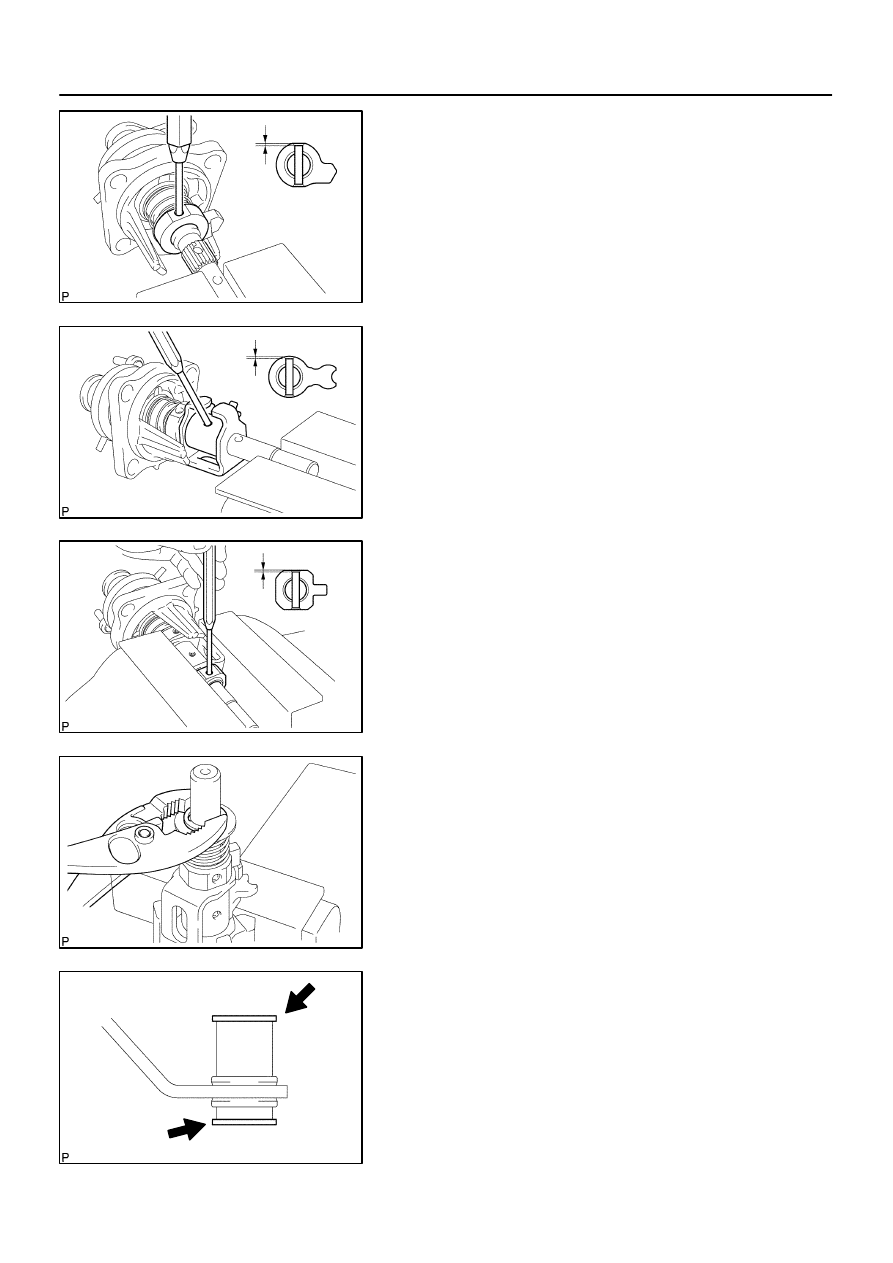
C80581
C80582
C80583
C80584
C80571
41–96
–
MANUAL TRANSMISSION/TRANSAXLE
SHIFT & SELECT LEVER SHAFT ASSY (C59)
1496
Author:
Date:
2004 COROLLA (RM1037U)
14.
INSTALL SELECT INNER LEVER
(a)
Coat the select spring seat No.1 with MP grease, install
it to the shift & select lever shaft.
(b)
Install the select return spring and select inner lever to the
shift & select lever shaft.
(c)
Using a pin punch (
φ
5 mm) and a hammer, install the
slotted pin to the select lever inner lever.
Drive in depth: 3.0 – 4.0 mm (0.1181 – 0.1575 in.)
15.
INSTALL SHIFT LEVER INNER NO.1
(a)
Coat the shift interlock plate and shift lever inner No.1 with
MP grease.
(b)
Install the shift interlock plate with shift lever inner No.1 to
the shift & select lever shaft.
(c)
Using a pin punch (
φ
5 mm) and a hammer, install the
slotted pin to the shift lever inner No.1.
Drive in depth: 0
0.5 mm (0
0.0197 in.)
16.
INSTALL SHIFT LEVER INNER NO.2
(a)
Install the shift lever inner No.2 to the shift & select lever
shaft.
(b)
Using a pin punch (
φ
5 mm) and a hammer, install the
slotted pin to the shift lever inner No.2.
Drive in depth: 0
0.5 mm (0
0.0197 in.)
17.
INSTALL SELECT SPRING SEAT NO.2
(a)
Coat the select spring seat No.2 with MP grease, install
it with select return spring to the shift & select lever shaft.
(b)
Using a plier, install the E–ring to the shift & select lever
shaft.
18.
INSTALL SELECTING BELLCRANK NO.2 BUSH
(a)
Coat the selecting bellcrank No.2 bushes with MP grease,
install them to the selecting bellcrank.
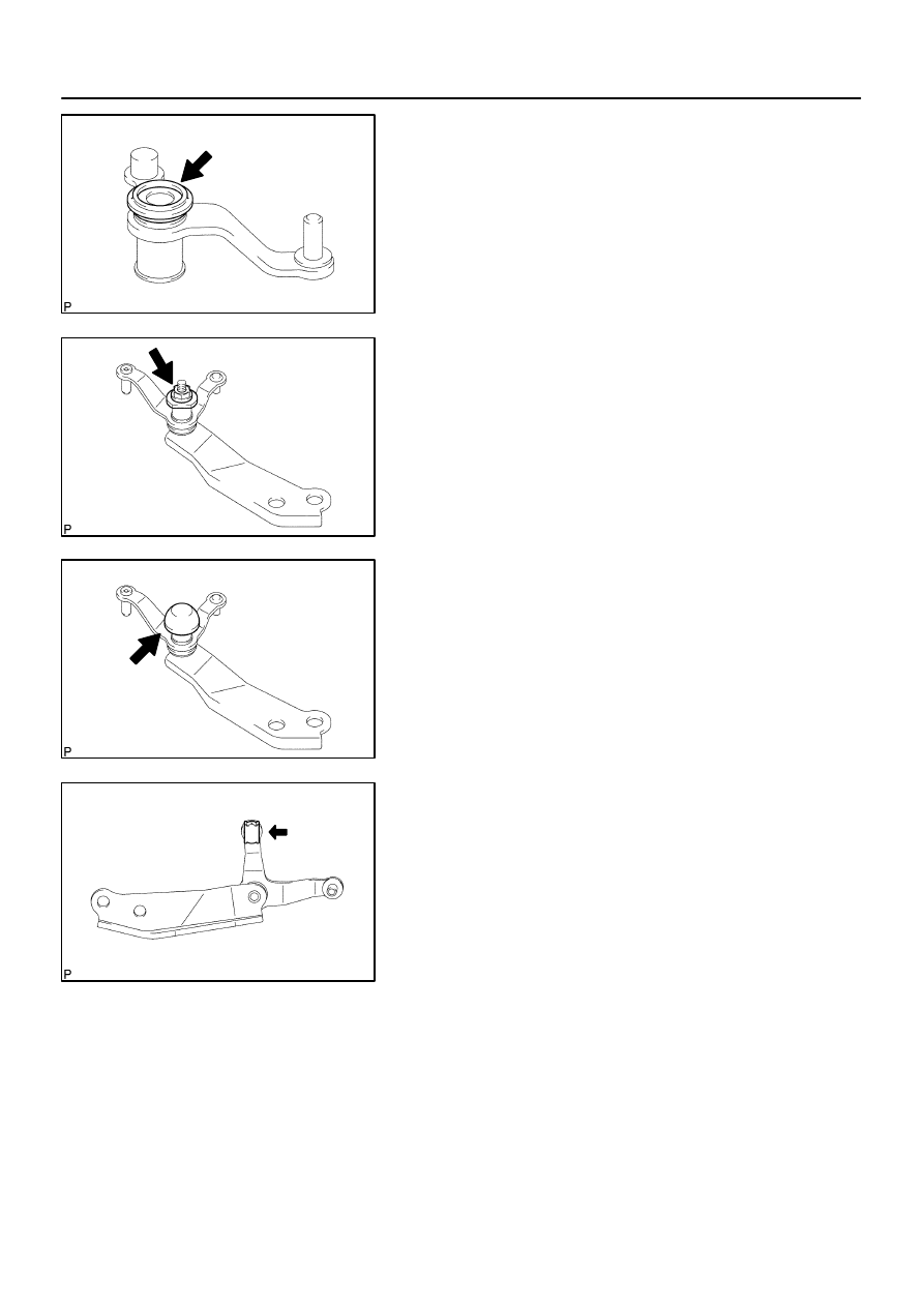
C80763
C80762
C80761
C80760
–
MANUAL TRANSMISSION/TRANSAXLE
SHIFT & SELECT LEVER SHAFT ASSY (C59)
41–97
1497
Author:
Date:
2004 COROLLA (RM1037U)
19.
INSTALL SELECTING BELLCRANK DUST COVER
NO.2
(a)
Coat the selecting bellcrank dust cover No.2 with MP
grease, install it to the selecting bellcrank No.2.
20.
INSTALL SELECTING BELL CRANK NO.2
(a)
Install the selecting bellcrank No.2, selecting bellcrank
No.2 plate washer and spring washer with nut.
Torque: 11.8 N
⋅
m (120 kgf
⋅
cm, 9 ft
⋅
lbf)
21.
INSTALL SELECTING BELLCRANK DUST COVER
NO.1
(a)
Install the selecting bellcrank dust cover No.1 to the se-
lecting bellcrank assy.
22.
INSTALL CONTROL SHIFT LEVER BUSH
(a)
Coat the control shift lever bush with MP grease, install it
to the selecting bellcrank assy.
Wyszukiwarka
Podobne podstrony:
41 Manual Transmission Transaxle
41 Manual Transmission
41 Manual Transmission Transaxle
MANUAL TRANSMISSION & TRANSAXLE
2610 Manualo transmission, checking & correcting oil level
2601 Manual transmission oil change
G 2 0 DOHC Manual Transmission System doc
Chrysle Auto Manuals Lebaron Transmision A604 ATSG 1
Eaton FS8209 Transmission parts manual
Chrysle Auto Manuals Lebaron Transmision A604 ATSG 1
Kenwood W 41 U Service Manual
Transmisja WAP
Sieci media transmisyjne
41 etapy rozwoju dziecka
Media Transmisyjne
noj 41
(41) Leki zwiększające krzepliwość
analiza kosztow produkcji (41 str)
więcej podobnych podstron