
Home Power 2 January 1988
2
3
Home Power
Home Power People
for Issue 2
Paul Cunningham
Windy Dankoff
Brian Green
Don Hargrove
Glenda Hargrove
Stan Krute
Alex Mason
Karen Perez
Richard Perez
Dave Winslett
& Laser Work by
IMPAC Publications
Ashland, OR
From Us to You- 4
Solar- Pvs and our Future An Editorial - 6
Systems– A Working PV/Engine System – 7
Solar– How to Mount and Wire PV Modules – 11
Communications– Back Country Com – 16
Hydro- Seeking Our Own Level- 17
Free Subscription Forms- 19 to 22
Engines– Build Your Own 12VDC Generator – 23
Heat– The Fireside – 27
Things that Work-- The Trace 1512 Inverter – 29
Batteries-- Build an Accurate Battery Voltmeter – 31
Basic Electricity-- Low Voltage Wiring Techniques –33
Letters to Home Power- 37
Home Power Magazine is
a division of Electron
Connection Ltd. While we
strive for clarity and
accuracy, we assume no
responsibility or liability for
the usage of this
information.
Copyright
©
1988 by
Electron Connection Ltd.
All rights reserved.
Contents may not be
reprinted or otherwise
reproduced without written
permission .
Home Power Magazine
Post Office Box 130, Hornbrook, CA 96044-0130
telephone: 916-475-3179
Home Power 2 January 1988
From Us to You
Home Power 2 January 1988
Thanks to all of you who responded to the first issue of Home
Power. The support, praise, and information has been
overwhelming. At times, working on the first issue, we
wondered if anyone really cared about home style AE. We no
longer doubt. Your response has replaced doubt with
certainty. We are everywhere, and we care about energy and
the environment.
Everytime another batch of subscription returns comes in
(about 100 per day), all other work stops. Everyone opens and
reads your comments. Your interest and support has warmed
our hearts and given us the energy to carry on. It's like
re-meeting old friends.
Many of you have asked who and what is Home Power
Magazine. Well here are the facts of the matter. Home Power
is basically 3 of us (Glenda, Karen & I) working full time, 3
others part-time and many folks contributing information and
articles. We are not financially supported by anything or
anyone other than the ad space we sell. We started Home
Power about a year ago with less money than it takes to buy a
used car. It took us 8 months to sell enough ads to put the first
issue in your hands. It has taken us 2 months to sell enough
ads to produce this issue. To date, all revenue has been spent
on printing and mailing; no one has received any salary.
We've been doing it for free because we have faith in this
project and AE. We have high hopes. The challenge for us is
to deliver Home Power to you free and make enough out of it
to eat regularly. Time will tell.
Some of you have been sending money to help out. We thank
you for this, it has certainly helped. We are not going to
charge a subscription fee, even though many of you have
written you would cheerfully
pay for this info. However, if
you can afford it, and wish to
send us whatever you think
Home Power is worth to you,
then thanks. It'll help out.
For those who haven't yet
responded to Home Power,
please fill out the Subscription
Form. Some of the forms
have arrived damaged in the
mails. If you are not getting
your copy of Home Power,
please let us know. We are
listening to your ideas &
comments. This issue has
information you have
requested. Keep telling us
what you want to know and
we'll do our best to get it into
Home Power.
This month begins our
THINGS THAT WORK
articles. Many of you have
asked for specific equipment
tests and recommendations.
Well, Home Power is
supported entirely by
advertising, so this puts us in
a delicate position. Here is
our idea concerning specific
equipment testing and recommendations. Actually, its not
really our idea, we borrowed it from Thumper Rabbit: "If you
can't say something nice about something, then don't say
anything at all."
We will test and recommend specific types and brands of
equipment in the THINGS THAT WORK columns. In order for
a piece of equipment to be featured in this column it must meet
three criteria:
1) It must do its job as specified by its manufacturer. This is
determined by actual objective testing in running AE systems.
2) The equipment must survive. Once again this is
determined by real life testing in actual AE systems.
3) The equipment must represent good value for the money
spent on it.
If you see equipment in the THINGS THAT WORK (TTW)
columns, then you can purchase it and know that it met the
three criteria above. Equipment not meeting these criteria will
not be in the TTW column. This gives manufacturers that don't
meet these criteria a chance to try again. We are a fledgling
industry. A bad review can kill a small company. We are
interested in fostering the growth of AE. And as such we are
going to follow Thumper Rabbit's advice. Any comments on
this?
Our Thoughts on Alternative Energy People
Consider AE people as pioneers. When we move beyond
commercial power we have, by definition, moved to the edges
of society. Power lines, like crime, disease and pollution,
follow the spread of mass culture. AE people are truly
pioneers. Not only in an electrical sense, but also on the
frontiers of attitude and perspective.
Krute
87
4
From Us to You
Home Power 2 January 1988
What we are doing now is novel-- we make our own
power instead of relying on someone else. We have
chosen this for many reasons-- the best deals in
property are beyond the power lines, the desire to do for
ourselves, our concern for our environment, and many
other reasons. Whatever the reason, we are all charting
new routes to self-sufficiency and happiness. What we
are doing now may be unusual, but our efforts point the
way to a livable future we can all share.
Resources now used commercially to produce electricity
are finite. We are using them up at an alarming rate.
The consequences of unrestricted combustion, tinkering
with the atom's interior, and damming our rivers are now
apparent. "Only a stupid bird fouls its own nest." The
world's peoples are looking for something better,
something that can provide our power without polluting
and bankrupting future generations.
Alternative energy users light the way to a better future.
So, stand up, give yourself a pat on the back. You
deserve it. Thanks for having the courage to look the
future (not to mention the power company) in the face
and not flinch.
We cannot personally answer your letters and
comments, the volume is simply too great. We are
starting a letters column in this issue. We encourage
you to send your AE experiences to Home Power. We
will print articles, comments and letters written by
readers. The only requirement is the communication of
information and experience. Home Power is a forum for
this exchange. Information stands on its own merits,
and any having merit will be communicated within these
pages. So let other Home Power readers learn from
your experiences. In the words of Bob Dylan, "You can
be in my dream if I can be in yours." Let's dream
together...
Rich, Karen, Glenda & the Whole Crew
HELIOTROPE GENERAL
3733 Kenora Drive, Spring Valley, California 92077 · (619) 460-3930
TOLL FREE: In CA (800)552-8838 · Outside CA (800)854-2674
Invest in
The Best!
PSTT™ Inverter
A new era in inverter design!
Phase Shift Two-Transformer 2300 Watt Output
Input Voltages 12, 24 VDC, Output Voltages 117/230 VAC
5
Features:
* Fully protected, including:
* Efficiency up to 95%
* Surge Power to 7000 Watts
* Standby Battery Power
under 0.5 Watts
* Unique patented design
starts and runs any load
Overcurrent
Overvoltage Spikes
Overtemperature
High Battery
Low Battery
Reverse Polarity
Charge Controllers and
PV DWH Systems also.

Solar
Home Power 2 January 1988
Photovoltaics and Our Future-- an Editoral
by
Windy Dankoff
Our concept is site produced and consumed energy. Home Power. Perhaps no source better fits our future energy demands than the
photovoltaic (PV) cell. This editorial presents some thoughts on one of our possible energy futures, this one using the PV- RP.
Solar cells are made of inert mineral materials, similar to
ordinary sand. These cells convert light directly into electricity
without moving or wearing parts. Silicon crystal cells have
been in use since 1955 and their life expectancy appears to be
limited by the materials sealing them from the elements.
Today's high quality PV modules are a permanent investment-
future improvements will NOT render them obsolete.
PV technology has significant advantages to the small-scale
user:
1) PVs are BENIGN. In use, it consumes only sunlight and
presents no significant hazards or environmental alterations.
There is almost no way to abuse PV energy. Even
short-circuiting the modules will not harm them.
2) PVs are UNIVERSAL. The world's largest megaWatt
arrays are made up of small modules, similar to those used in
remote homes. PVs are an energy technology where progress
in utility/industrial scale systems trickles down to the small,
independent user. PV modules produce energy from light, not
from heat. In fact, they're most efficient when they are cold!
We have sent PV systems as far north as the Arctic Circle.
People simply don't live where the sun never shines. Everyone
has PV potential!
3) PVs are MODULAR. You can start with a small array and
expand as you wish.
4) PVs are virtually MAINTENANCE-FREE. You need not be
technically talented to clean off leaves, snow or bird droppings.
As PVs Get Less Expensive...
Retail prices of PV modules have been dropping by
≈
15% per
year since the last big price breakthrough in 1979, when prices
dropped 300%. Many people continue to wait for another big
break to happen, and are quite unaware of the gradually
decreasing cost of PVs. Technical innovations, reported as
potential breakthroughs over the past ten years, are available
NOW. The prices just never dropped suddenly enough to
make front page news.
While we all anticipate continuing price drops, please keep in
mind that the costs of the PVs themselves is only 20% to 40%
of an installed cost of a typical PV home system. The general
public continues to buy and use appliances and lighting that
are so inefficient that even if PVs were free, few people could
afford the huge battery bank, inverter, etc. required to power
their homes. To continue present trends in energy abuse and
waste, while waiting for price breakthroughs in PVs, is to
completely miss the point of energy independence. The point
is to pay attention to the design of an entire system, not just
the price of the PVs.
As PV prices continue to drop, we foresee the use of more
powerful solar arrays as a more significant trend than reduced
system costs. Oversized PV arrays on homes will allow them
to perform like the popular solar calculators, reliable even in
dim light and affordable in cloudy climates.
What you see in this magazine-- efficient and reliable batteries,
inverters, controls, appliances, and the techniques of energy
management-- are the result of over 20 years of quiet
revolution in energy technology. Right NOW, an estimated
30,00 American homes are powered primarily by PVs. In fact,
you are already a PV user. Many of the radio/TV broadcasts
you receive and the phone calls you make are relayed by PV
powered satellites. The Home Power Magazine you are now
reading is composed and illustrated using PV powered
computers. An increasing number of appliances, from watches
to yard lights, are PV powered. PVs have found many
commercial uses-- radio repeaters, livestock watering, electric
fencing, ocean navigation buoys, billboard & sign lighting, and
the monitoring of remote pumps, pipelines, and the weather.
The uses of PVs are only limited by our audacity and
imagination.
PV technology stands ready to economically and reliably serve
the greater public. All that stands between us and a healthier,
solar powered society is OUR understanding, acceptance and
support. PVs are ready for us. One purpose of this magazine
is to get US ready for PVs.
Windy Dankoff is the Owner and Operator of the Windlight
Workshop. He's been doing it right since 1977. You can write
him via POB 548, Santa Cruz, NM 87567. Check out his ad on
page 40.
6
Systems
Home Power 2 January 1988
A Working PV/Engine AE System
by
Richard Perez
any readers of Home Power are asking for real examples of working AE systems, complete
with specific equipment lists, performance data, and cost analysis. Well, we hear you and
here is the first of our system reports. Please remember that this and all working systems
represent a compromise between many factors. Location, electrical power needs, finances,
and hardware availability all make their impressions on the working system. Alternative energy
systems are a process: we enter and leave this process in the middle. Nothing here ever really has
a start or a finish. Changing needs and emerging technologies make it best to plan for change. So
read ahead and see how this family rolls their own power.
Location & Site:
John and Anita Pryor live high in the Siskiyou Mountains of
Northern California. Their homestead is about 3 miles from the
nearest commercial utility. Altitude is about 3,200 feet with a
panoramic view of Mt. Shasta some 50 miles to the South.
Solar insolation is about 240 full sun days yearly. While the
location appears to have wind potential (at least in the
Summer), no real survey of wind conditions has been made at
the Pryor's location. Water sources at this site, while more
than enough for domestic use, lack the fall or flow for hydro
power potential. The commercial electrical utility wants just
under $100,000. to run the power lines to John & Anita's
homestead.
Electrical Power Usage
The Pryor's household represents a fairly standard
consumption profile for two people living on alternative energy.
Their appliances include a 12 VDC electric refrigerator/freezer,
a 12 VDC B/W TV set, 120 VAC lighting, 22" color 120 VAC
TV, 120 VAC Video Cassette Recorder, 120 VAC Sewing
Machine, various 120 VAC kitchen and household appliances.
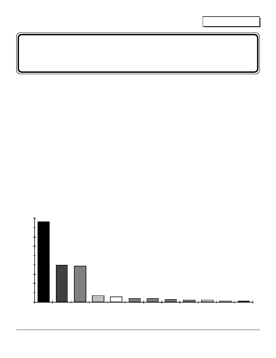
A detailed profile of how John & Anita use their homemade
electricity is in the column graph shown in Figure 1.
The vertical axis of the graph is calibrated in Watt-hours per
day, while the horizontal axis details the various appliances.
The Pryor's total electrical power consumption is about 2,030
W-hrs. per day. Their consumption is both 12 VDC from the
batteries, and 120 VAC from the inverter. DC portion of the
consumption is about 1,372 W.-hrs./day, while the remaining
M
0
100
200
300
400
500
600
700
800
900
DC TV
Lighting
CB RX Color TV
Fan
Vacuum
VCR
Invert
Idle
Stereo
Sewing
Machine
CB TX
864
400
390
72
57
40
37.5
28.5
24
23.1
12.5
12.5
DC Frig/
Freezer
Appliances
Figure #1
John & Anita Pryor's Electrical Consumption
7
Systems
Home Power 2 January 1988
656 W.-hrs./day are AC via the inverter. John and Anita are
into energy conservation, their daily electrical consumption is
less than 20% of the average American household.
DC Appliances
From the graph it is very apparent that the largest single user
of electricity in John & Anita's system is the 12 VDC
refrigerator/freezer. This 12 cubic foot refrigerator/freezer
consumes about 860 Watt-hours per day on the yearly
average. While this amounts to 48% of the energy the Pryors
produce and use, it is very low in comparison with conventional
refrigeration. Specialized AE refrigerator/freezers are initially
more expensive than their standard household counterparts,
but they quickly pay for themselves by saving energy.
Two other DC appliances are worthy of note.
The 12 VDC B/W TV allows low powered
viewing and doesn't require the use of the
inverter. The CB radio is the homestead's only
communication and is also 12 VDC powered.
Note that the receive and transmit states of the
CB are detailed separately in the consumption
profile. This technique works for other
appliances that consume energy at differing
rates as they perform their functions.
AC Appliances
The Pryor's use about 390 W.-hrs. per day in
lighting. They are currently using 120 VAC
fluorescent types for about half their lighting,
with incandescent 120 VAC lightbulbs picking
up the remainder. All lighting is powered via
the inverter. John is going to installing 12 VDC
fluorescent lighting in the future.
All other usage of 120 VAC really doesn't
amount to much in terms of energy
consumption. This is one nice feature of
inverter type systems. Standard household
appliances such as color TVs, stereos, vacuum
cleaners, and sewing machines can be used
with the inverter. Even though some of these
appliances consume substantial amounts of
energy while running, they are only running
occasionally for short periods of time. Consider
the case of a vacuum cleaner. A vacuum may
consume some 400 Watts of power, but if it is
only used about 5 minutes daily, then its total
energy consumption is about 33 Watt-hours per
day. Not a very substantial amount of power
when compared with the cleaning wonders
accomplished by the vacuum. The situation is
much the same for many AC appliances.
SYSTEM HARDWARE
The AE system the Pryors are now using was
first specified and modeled by the
EnergyMaster computer program. This
program, written by the Electron Connection
Ltd., simulates the operation and costs of
solar/engine systems. Its use allowed the
Pryors to properly size their system to meet
their specific needs at the lowest possible cost.
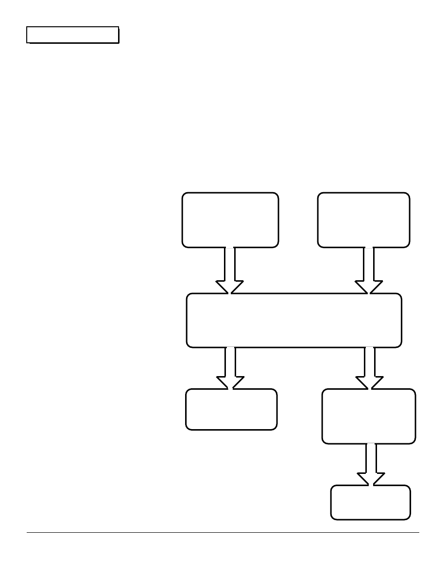
A diagram on this system is contained in Figure
2.
Power Sources
The Pryors use two energy sources- photovoltaics and a
homemade 12 VDC gasoline engine/generator. The computer
specified eight PV panels, each 48 Watts, for this system.
However, finances forced John and Anita to make do with only
four 48 Watt Kyocera photovoltaic modules. These 4 modules
produce about 950 Watt-hours of energy on an average sunny
day at John & Anita's location. This makes their system about
47% solar powered. One of the nice things about PVs is their
expandability. John and Anita can add more panels to their
system whenever they wish. The cost of the four Kyocera PV
modules was $1,400.
The mounting rack made by John and Anita is simple to build,
very strong and inexpensive. This rack uses standard
4 Kyocera
48 Watt
Photovoltaic Modules
1500 Watt
Homemade DC
Engine/Generator
Battery Pack
4 Trojan L-16 W Lead Acid Batteries
700 Ampere-hours at 12 VDC
12 VDC
Loads
1500 W.
Trace Inverter
Battery Charger
120 VAC
Loads
Fig. #2- Pryor's AE System Diagram
8

Systems
Home Power 2 January 1988
hardware store materials and adapts easily to wall, roof, or
ground mounting. The rack also allows seasonal elevation
adjustment of the 4 panels it holds. Construction of this rack is
covered in this month's Solar article. The cost of the mounting
rack was $75.
The remainder on the power is produced by a homemade
engine/generator set. This unit uses a single cylinder,
horizontal shaft, gas engine to drive an automotive alternator.
This engine/generator set is capable of delivering 40 amperes
of 12 to 16 VDC directly to the batteries. A field controller,
made by Electron Connection, regulates both the alternator's
output current and voltage. Details for the construction of this
engine/generator and its control system are featured in this
month's Engine section.
While this generator does consume gas and is noisy, it allows
the Pryor's to get by until they have more PVs. When they do
add more PVs to their system, then the generator quietly
recedes into the background, only to be run during extended
cloudy periods. Such an engine/generator costs about $750.
to construct. This represents a first class job- Honda OHV
motor, high Amp. alternator (we like the 100 Amp. Chrysler
models), welded steel base, control system and heavy cast
pulleys.
Power Storage
John and Anita use four Trojan L-16W batteries to store their
electricity. This series/parallel battery pack stores 700
Ampere-hours of 12 VDC energy. This amounts to about
8,600 Watt-hours of storage. Once the batteries have been
derated by 20% (if you don't know why, then see Home Power
#1- Battery article), there is 6,900 Watt-hours of usable energy
stored in the battery. At the rate that John and Anita consume
power, this battery pack stores about 3.3 days worth of energy
for them. The cost of their batteries was $880. With proper
care we expect these batteries to last about 10 years. Details
on proper battery cycling and care are in Home Power #1.
John & Anita located the batteries in their kitchen directly
opposite their woodstove. While Anita is not happy about
having them inside, she realizes the importance of keeping her
batteries warm in the Winter. The preceding year, the Pryor's
kept their batteries outside in the cold. They noticed the
substantial decrease in the batteries capacity due to cold
temperatures.
Power Conversion
The Pryor's are using a Trace 1512 inverter with built-in battery
charger. This inverter converts the DC energy produced by the
PVs and stored in the batteries into conventional 120 VAC, 60
cycle house power. It has a rating of 1,500 Watts output. John
purchased the built-in battery charger even though he now
lacks the 120 VAC powerplant necessary to drive it. John is
looking forward to the day when he will have a large AC
generator to handle periods unusual power consumption.
The Trace contains a metering package that is very useful.
John and Anita rely on this package for most of their system
metering. This LED digital meter reads battery voltage, charge
current from the built-in charger, and peak voltage plus
frequency of any 120 VAC power source feeding the charger.
This metering package is just the ticket for generator users.
They can adjust the frequency of their powerplants using this
meter's information. The Trace's battery charger accepts 120
VAC from a powerplant and recharges the batteries. John now
has a small 650 Watt, 120 VAC Honda generator, but it lacks
the power to effectively run the 80 ampere charger in the Trace
inverter. The best it can manage is about 27 Amps into the
batteries. This inverter cost John and Anita $1,458. with the
optional charger and metering package.
John and Anita have nothing but praise for their Trace inverter.
It powers all the AC appliances they brought with them to their
mountain home. John likes the way he can use his wall full of
stereo and video equipment. Anita spends many hours
working with her sewing machine. All these appliances are
standard 120 VAC household models. The Trace inverter
makes their operation possible and efficient on PV produced,
battery stored, DC energy.
SYSTEM OPERATION
The batteries will store enough energy for 3.3 days of
operation. On an average basis, the four PV panels extend
this storage period to about 5 days between generator
rechargings. This amounts to generator operation about every
4 days during the Winter months and about once a week
during the Summer. John and Anita are putting some 1,100
hours yearly on their mechanical generator. This costs them
about $30. per month in fuel and maintenance.
John and Anita are their own power company. They both
watch their battery voltage and electrical consumption like
hawks! Generating their own electricity has taught them the
lessons of conservation and energy management. They are
looking forward to completing their system by adding more PVs
and more batteries. Four more PV modules will make them
almost totally solar powered. This will reduce their operating
expenses and allow them to use more energy. Anita has a
washing machine on the back porch that she's giving the eye.
Since the data was collected for this report, John has moved
his refrigerator/freezer. This move from the warm kitchen to
the much colder back bedroom has cut John's wintertime
power consumption by about 40%. One such details the
success or failure of AE systems rest.
John reports that no matter the season, he can leave his
system unattended and be sure of ice cubes in the freezer &
full batteries when he returns. Thanks to the four PV modules
on the roof. Since the four modules only produce 12 Amps or
so in full sun, there is no need for regulation. The full current
output of the modules is about a C/50 rate, far too slow
overcharge the hefty L-16 battery pack of 700 A-H.
System Cost Data
The Pryors have spent about $4,700. on hardware to this point.
This is substanially less than the $100,000. or so the power
company wanted just to run in the lines (never mind the
monthly bill). With a current operating cost of $30. per month,
this system supplies their electricity at about $1.10 per
kiloWatt-hour. This figure includes all hardware and fuel
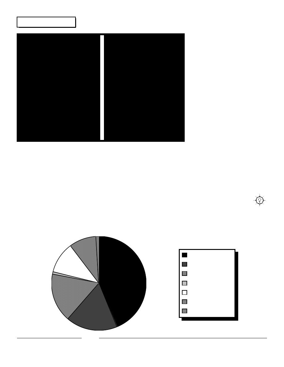
amortized over a ten year period. Fig. 3 shows how the money
is spent in this system. Note that their expenditure for fuel is
still substantial. If you add it all together, it costs John and
Anita about $8,000. to buy and operate the system they now
have for a ten year period. Not a bad solution to back country
electrical needs. And at 8% of the power line cost! With the
addition of 4 more PV modules, the system will become more
efficient and produce its power for about $1.00 per
kiloWatt-hour. These additional panels will reduce the
generator operating time to 450 hours yearly and the operating
9
Systems
Home Power 2 January 1988
cost to about $10. per month. It will also extend the average
storage in the 4 batteries from 5 days to over 11 days.
That's it for our first system review. Please write us and let us
know if this is what you had in mind. Once again, this is a real,
operating system; not a computer simulation. While it may not
be texbook ideal, it does show what can be done with initiative,
perserverance, and a limited budget. If you want to
correspond directly with John and Anita Pryor, drop them a line
at POB 115, Hornbrook, CA 96044.
Fuel & Maintenance
Inverter
PVs
PV Rack
Batteries
Engine/Generator
Misc.
43.70%
17.70%
16.99%
0.91%
10.68%
9.10%
0.91%
Fig. #3- The Bottom Line-- Where John & Anita's AE Bucks Go
10
Solar
Home Power 2 January 1988
How to Mount and Wire PV Modules
by
Richard Perez
his article explains how to make your own PV mounting rack, how to install it, and how to wire
up the whole works. This is in response to many reader requests for this info. So, all you PV
panels languishing under beds, relaxing in closets, and vacationing in garages: Listen Up,
here's your chance to get your people to put you in the Sunshine to do your thing.
Face It SOUTH
The critical consideration in mounting PV modules is the
yearly path of the Sun. The PV modules must receive
maximum sunlight. Consider shading from trees and
buildings. The decision of where to mount should be made
only after careful consideration of all your options.
The PV modules, in most nontracking situations, should face
South. The closer the plane of the rack is to facing true
South, the better overall performance the PVs will deliver.
Only consider mounting surfaces that are within 15° of facing
true South (within 10° is much better). Any surface further off
will require more complex, asymmetrical mounting racks. If
you don't have a roof or wall that is suitable consider ground
mounting. Since PVs produce low voltage DC current, keep
the wire lengths to the battery as short as practical. See the
Basic Electricity article in this issue dealing with wire sizing in
low voltage DC systems for specifics.
Where you are going to put your PVs determines the type of
rack you need. Roof mounting (on either pitched or flat roofs),
wall mounting, and ground mounting are all possibilities. So
consider the variables and pick the best for your situation.
These racks can be used in all three types of mountings.
So Which Way is South?
Determine South with a good compass and someone who
knows how to use it. Be sure to allow for the difference
between magnetic North and true North. This difference is
called magnetic declination. In California for example
magnetic North is some 19° East of true North. If you don't
know your magnetic declination, then go to the library and
look it up.
Mounting Racks-- your PVs hold on the
World
The obvious purpose of the rack is to attach the panels to a
fixed surface. At first glance this seems simple enough, but
consider wind, snow, falling ice and temperature variations,
not to mention possible leaks in the roof!
We are going to talk about a simple to build rack that can hold
up to four panels. This rack uses inexpensive hardware store
parts. It mounts on roofs, walls, or on the ground with the
appropriate foundation. In all mounts, the rack is adjustable
for panel elevation, and allows seasonal optimization of the
racks tilt. This rack approach was developed by Electron
Connection Ltd. for its customers. Its design and application
are so simple that I'm sure many others are using just about
the same technique.
The Rack Materials
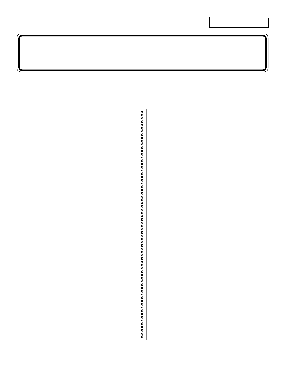
The rack is constructed out of slotted, galvanized, steel angle
stock. This stock is available at most hardware stores. Our
local store sells National Slotted Steel Angle (stock #180-109)
for about $7.00 each retail. This stuff is 6 feet long, with two
perpendicular sides each 1.5 inches wide. The stock is about
1/8 inch thick, with a heavy galvanized coating. Its entire
length is covered with holes and slots that will accept 5/16
inch bolts. We have had no problems with corrosion or
electrolysis with this galvanized stock after three years in the
weather. We haven't yet tried this material on a seacoast, and
would welcome feedback from anyone who has. To the left is
a drawing of a typical length of this steel angle.
You can shop around locally, and may encounter different
sizes and lengths. Six foot lengths are long enough to mount
4 of just about any type of module. We use this angle on
Kyocera, Arco and Solec panels without having to drill any
holes in either the angle or the PV modules. Working with this
stock is like playing with a giant erector set. The only tools
you really need are wrenches, a hacksaw (to cut the angle),
and a drill for making holes in the surface holding the rack.
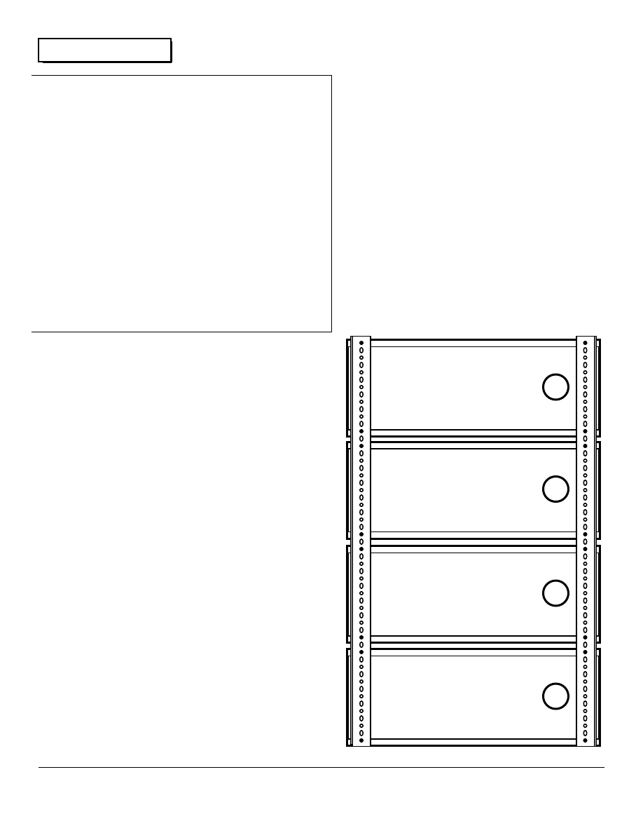
The amount of steel angle stock you need depends on the
size & number of panels you wish to mount, the mounting
location, and your particular environment. Let's consider the
rack shown in the photoon the next page as an example. This
rack holds four 48 Watt Kyocera PV modules and is bolted to
the almost horizontal metal roof of a mobile home. Each PV
module is 17.4 inches wide and 38.6 inches long. The
mounting holes on the bottoms of the PV modules match the
hole cadence in the slotted angle. This particular rack used 9
of the 6 foot lengths of the steel angle. Four lengths comprise
the framework for the modules. Three lengths make up the
legs and bracing, while two more lengths are used as skids on
the roof. Strictly speaking, the skids are not essential, but do
add rigidity and relieve stress on the mounting points on the
sheet metal roof. We don't want any leaks.
A rack could be built with the about half the materials. The top
and bottom pieces of the rack holding the panels, the brace on
the legs, and the skids could all be deleted. If this were done
then the rack would be roughly equivalent to most commercial
models. In our opinion, PV modules should be mounted as
securely as possible. Many commercial racks use the PV
modules' frames as a structural members in the whole
module/rack assembly. This rack does not do this. Many
T
11
Solar
Home Power 2 January 1988
commercial racks use 1/8 inch aluminum angle. This rack
uses steel of the same thickness; it is much stronger.
This rack lives in snow country, with lots of high winds.
Consider that the rack holds some $1,400. worth of PV
modules. We figured that the additional $35. the extra bracing
costs to be worth it in terms of security. It's comforting to be
inside during a howling snow storm and know that when its all
over the PVs will still be there. Don't skimp on materials for
your rack. Use extra bracing to make it as strong as possible.
Remember that it holds over a thousand dollars worth of PV
modules. The 9 pieces of slotted angle cost us about $65.,
and are well worth it.
Laying Out the Rack
You could design the entire rack on paper after first making all
measurements of the critical dimensions on the modules. This
takes time, and is subject to measurement inaccuracies. We
have a simpler idea, with no measuring required. Let's treat
the entire project like an erector set. We assemble the entire
rack on the ground first, even if it must be disassembled to be
finally installed. This assures no surprises upon final
installation.
Lay a thick blanket or sleeping bag on a flat, smooth surface.
Place all the modules, face down on the blanket and lay on the
side angle pieces that connect the panels. See the diagram.
Note that no measurement is required. Simply align the
mounting holes in the module frames with the holes on the
angle. We usually leave any extra angle on these pieces,
rather than trimming it off. It comes in handy. On this
particular rack the 4 Kyocera modules mounted perfectly, with
no trimming of the 6 foot side rails necessary. The distance
between the mounting holes on the modules determines the
width of the rack.
Cut two pieces of angle to form the top and bottom rack rails.
These should be trimmed exactly to fit inside the framework
created by the side rails. The net result is all four panels are
encased by a perimeter of steel angle. Use 1/4 inch bolts
about 1 inch long, washers, lockwashers, and nuts to secure
the modules to the framework. The bolts on the corners of the
framework go through the module, the side rail, and the top (or
bottom) rail. The result is very strong.
If you don't have four panels to put on the rack right now, you
can use several pieces of angle stock in place of the missing
panels. We strongly recommend building the four panel
version. If you don't, then system expansion is going to be
harder. Also building a smaller rack costs about as much
when the waste on the 6 foot lengths of angle is considered.
So build for the future, and see how easy it is to add a panel or
two once their rack is already in place.
The Skids
We usually leave the skids uncut six foot lengths. The skids
form the base for roof, wall or ground mounting. If the rack is
to be wall mounted the situation is much the same except the
skids are vertical instead of horizontal. In all cases, one end of
the skid is connected directly to the module frame rails by
bolts. This forms a rotating hinged point for rack elevation
adjustment. This hinge line points East and West (so the rack
faces South) in horizontal applications, and up in vertical
12
Solar
Home Power 2 January 1988
the Fall increase the PV output by about 5 to 8%. This is really
not a very great increase in performance, but the success or
failure of an AE system depends on attention to detail. We
personally consider that a 5% increase in our PVs performance
is well worth the twice yearly expenditure of 15 minutes of our
time to adjust the rack.
On roofs that are not horizontal (and most aren't), the legs get
shorter as the roof gets steeper. A good overall,
nonadjustable, mounting angle is your latitude. If you live at
40° latitude, then mount the rack so that the angle between the
rack's face and horizontal is 40°. The table shows the proper
leg lengths for South facing roofs and a variety of latitudes.
This table assumes the use of 6 foot rack rails and skids. The
top of the table contains roof angles from 0 degrees (flat) to 60
degrees from the horizontal. The left side to the table shows
latitude in 5 degree increments. The actual leg lengths in feet
are in the body of the table.
Consider someone living at 38° latitude with a 25° slant on his
roof. The table shows a leg length of 1.36 feet. Note that this
table shows leg length decreasing as the roof's angle
approaches the latitude. Once the roof's angle becomes
greater than the latitude, the legs are attached to the bottom of
the rack rather than the top. Instead of raising the top of the
rack to face the Sun, we raise it's bottom.
If you're into math, the formula used to generate this table is
based on the Cosine Law. Here is a solved and generalized
equation that will give leg lengths for all situations regardless of
rack or skid dimensions, latitude or roof angle.
L= length of the Leg in feet
R= length of the Rack in feet
S= length of the Skid in feet
P= the angle of the roof's plane to the horizontal in degrees
A= your latitude in degrees
The geometry is much the same for wall mounting, but the
skids are vertical. In any case, don't be afraid to mount the
skids however you must, adjust the rack's elevation, and cut
the legs to fit. This approach while, low tech, gets the job done
applications.
The Legs
The actual length of the legs varies depending on where the
rack is mounted, your latitude, and whether or not you want
adjustability. The slant or pitch of a roof is another factor that
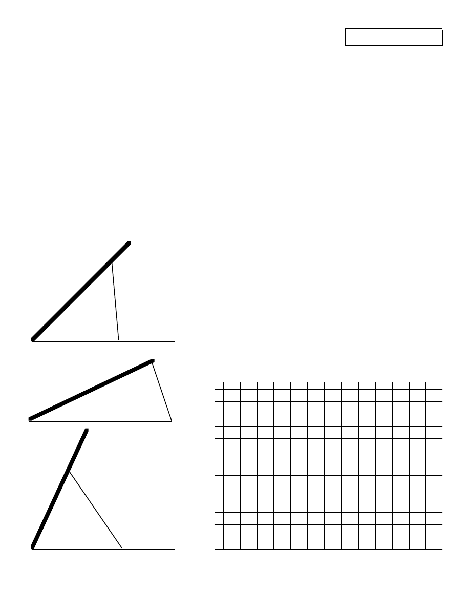
determines the length of the legs. Let's consider the simplest
case, that of mounting on a flat roof or on the ground. In this
case the skids are horizontal and level with the ground. Figure
4 illustrates the geometry of this situation for adjustable racks
for latitudes around 40°.
In the adjustable rack at 42° latitude, the legs are 3 feet, 4.25
inches long. Altitude adjustment is accomplished by unbolting
the legs and repositioning them along the rack rails and
mounting skids as shown in Figure 4. On a horizontal surface
these 3+ foot legs allow adjustment of the angle between the
rack and horizontal from 32° for Summer use, to 57° for Winter
use. Twice yearly adjustments during the Spring and again in
Fig. 4- Rack Geometry
LEG
RACK
SKID
0.00 5.00 10.0 15.0 20.0 25.0 30.0 35.0 40.0 45.0 50.0 55.0 60.0
60 6.00 5.54 5.07 4.59 4.10 3.61 3.11 2.60 2.08 1.57 1.05 0.52 0.00
55 5.54 5.07 4.59 4.10 3.61 3.11 2.60 2.08 1.57 1.05 0.52 0.00 0.52
50 5.07 4.59 4.10 3.61 3.11 2.60 2.08 1.57 1.05 0.52 0.00 0.52 1.05
45 4.59 4.10 3.61 3.11 2.60 2.08 1.57 1.05 0.52 0.00 0.52 1.05 1.57
40 4.10 3.61 3.11 2.60 2.08 1.57 1.05 0.52 0.00 0.52 1.05 1.57 2.08
35 3.61 3.11 2.60 2.08 1.57 1.05 0.52 0.00 0.52 1.05 1.57 2.08 2.60
30 3.11 2.60 2.08 1.57 1.05 0.52 0.00 0.52 1.05 1.57 2.08 2.60 3.11
25 2.60 2.08 1.57 1.05 0.52 0.00 0.52 1.05 1.57 2.08 2.60 3.11 3.61
20 2.08 1.57 1.05 0.52 0.00 0.52 1.05 1.57 2.08 2.60 3.11 3.61 4.10
15 1.57 1.05 0.52 0.00 0.52 1.05 1.57 2.08 2.60 3.11 3.61 4.10 4.59
10 1.05 0.52 0.00 0.52 1.05 1.57 2.08 2.60 3.11 3.61 4.10 4.59 5.07
05 0.52 0.00 0.52 1.05 1.57 2.08 2.60 3.11 3.61 4.10 4.59 5.07 5.54
00 0.00 0.52 1.05 1.57 2.08 2.60 3.11 3.61 4.10 4.59 5.07 5.54 6.00
L
A
T
I
T
U
D
E
MOUNTING SURFACE ANGLE
13
Solar
Home Power 2 January 1988
every time.
Mounting the Rack on a Roof
A roof is a difficult place to do a good job. The steeper the
roof, the more difficult the installation. On steep roofs we
prefer to assemble the whole rack, complete with PV modules
(already wired together), legs and skids on the ground. Then
transfer the whole assembly (about 50 pounds) to the roof for
final mounting. We have successfully used the skid mounting
technique on metal, composition shingle, composition roll, and
shake roofs from 15° to 45° of pitch.
Don't mount the PV modules themselves directly on the roof's
surface. PV modules require air circulation behind them to
keep them cool. If you are blessed with a pitch that equals
your latitude and a South facing roof, please resist the
temptation to mount the modules directly on the roof. The high
Summer temperatures underneath the modules will greatly
reduce their performance and can cause the actual PV cells to
fail. So leave at least 2 to 3 inches behind the modules for air
circulation .
Use at least 4 bolts (5/16 inch diameter) to secure the skids to
the roof. Use large fender washers inside the roof, and
lockwashers on the outside. Liberally butter the entire bolt,
washer and hole in the roof with copious quantities of clear
silicone sealer. When everything is tightened down and the
silicone sealer has set, we have yet to have any problems with
leakage.
Ground Mounting
If you are ground mounting, take care to pour or bury a
massive cement foundation for securing the skids. Ground
mounting exposes the PV modules to all sorts abuse. They
may be hit by everything from baseballs to motor vehicles. So
pick your spot wisely, and provide lots of mass to hold the rack
to the ground. Cement blocks, or poured cement strips are
best.
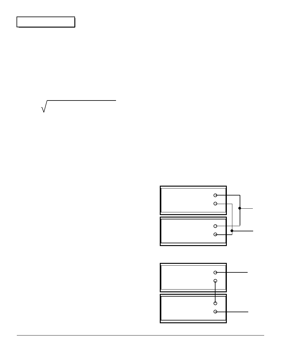
Wiring the PV Modules Together
PV modules are usually set up for 12 volt operation. The
module contains between 32 to 44 PV cells; each cell is wired
to the next in series. Thus the voltage of all the cells is added
to produce a nominal 14 to 20 volt output for recharging
batteries in 12 VDC systems. Each PV module is a
selfcontained polarized power source. Each module has a
Positive terminal and a Negative terminal, just like a battery.
The PV modules can be wired in parallel which adds their
current, or in series which adds their voltage. Systems using
12 VDC will wire the modules in parallel, which systems using
24 VDC or higher will wire the modules in series. Figure 5
illustrates the basic idea of either series or parallel wiring of PV
panels.
Use good quality heavy gauge copper wire (THHW or THHN
insulation) to make series or parallel connections between the
individual PV modules. Solder all possible connections. Most
modules use mechanical ring type connectors to connect the
L
=
R + S - 2RS Cos (A-P)
2
2
-
+
-
+
12
VDC
+
-
-
+
-
+
24
VDC
+
-
12 VDC
PV Module
12 VDC
PV Module
12 VDC
PV Module
12 VDC
PV Module
12 Volt Systems
24 Volt Systems
wiring to the actual panel. If you use these connectors, solder
the wire to them, don't just crimp the wires into the connector.
Use shrink tubing instead of tape on all wire to wire
connections. Be sure to use polarization indicators on all
wires. We use red tape at the ends of all positive wiring.
Wiring the PV arrays to the battery is straight forward, using
only two lines. These two wires carry the entire current of the
array. Total wire length (consider both wires) and array current
determine the wire gauge size necessary. See the Basic
Electricity article on low voltage wiring in this issue for specific
info on determining the wire gauge necessary for your PV
array.
It is a very good idea to electrically ground the framework of
your panels and rack. Make a good solid electrical connection
with the rack with a bolt assembly through one of the rack's
slots. Use at least 8 gauge wire connected to an 8 foot long,
copper flashed, ground rod. Drive the ground rod at least six
feet into the ground. Adequate grounding eliminates static
build up on the panels during thunder storms and may reduce
the possibility of actual lightening strikes on the panels.
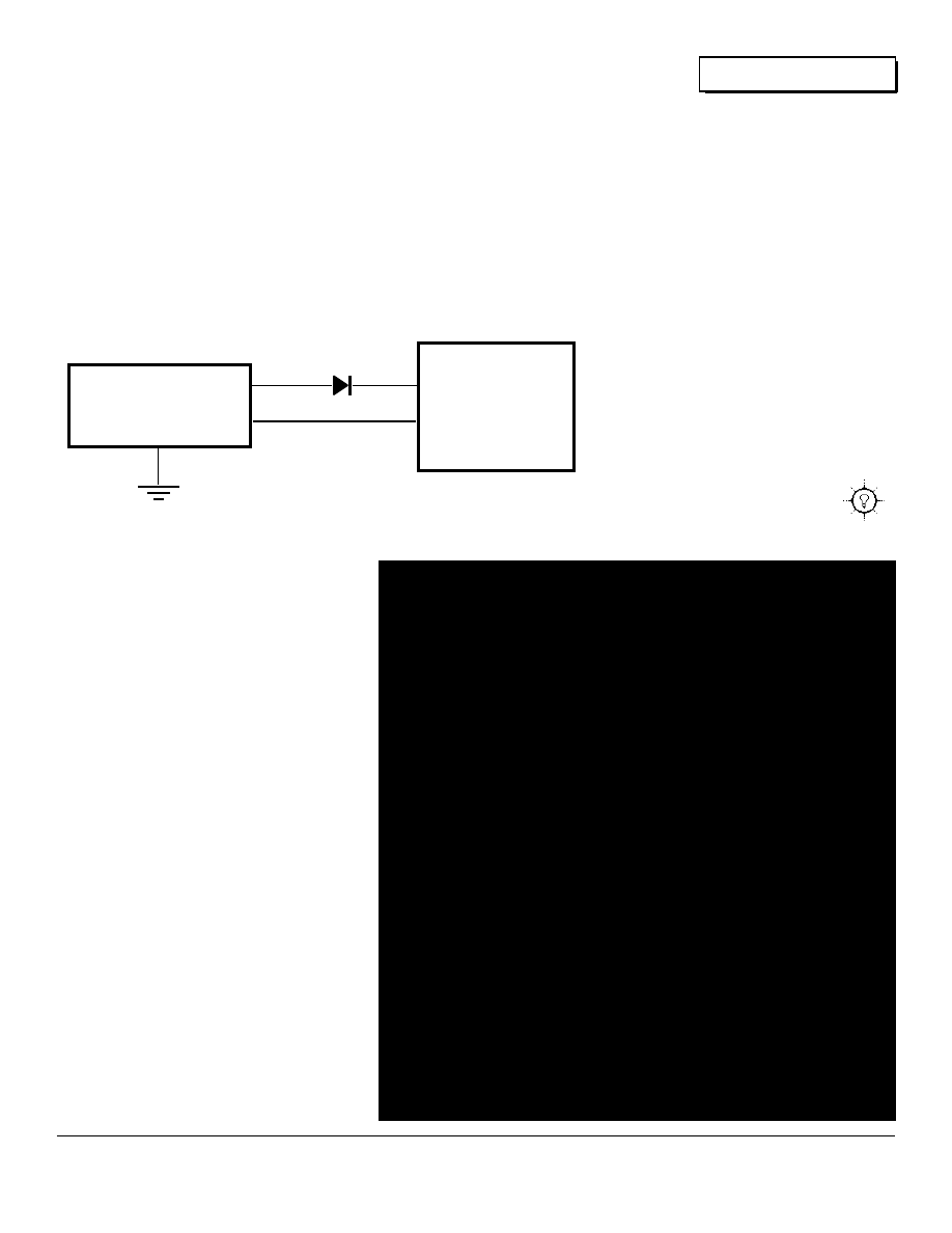
The only remaining electrical element in the system is the
addition of a diode to keep the array form discharging the
battery overnight. Our testing indicates that SOME panels
don't really leak too badly at night. For example, without a
blocking diode we measured a 44 cell in series Kyocera
Fig. 5- Wiring the PV Modules
14
Solar
Home Power 2 January 1988
module as leaking only .002 amperes at night. We, however,
still use a low loss diode inserted forward bias in the positive
line between the PV array and the battery. Use a Schottky (hot
carrier) power rectifier with a current rating at least double the
current output of the PV array. Use the appropriate voltage
rating for your system. The hot carrier type diodes have about
one third the voltage loss of regular silicon diodes. Figure 6 is
a wiring schematic of the 12 VDC sample PV system shown in
the photograph in Figure 2.
This wiring diagram does not contain any regulator for the PV
system.
Many
systems do not require a regulator for the PVs. A
good rule of thumb is: IF your PVs don't charge
the batteries at more than a C/20 rate, AND if the
system is ALWAYS being used, then you do not
need regulation. In other cases, wire the regulator
into the system following the manufacturer's
instructions.
This article gives you the basic information so you
can figure out what to do for your own particular
system. If after reading this, you don't feel
comfortable the concepts involved, please seek
the aid of someone to help. Proper positioning,
mounting and wiring of your PVs is essential if
they are deliver their maximum power.
12 VDC
Photovoltaic Array
+
-
+
-
12 VDC
Battery
Pack
Schottky Diode
1N6096
PV Array
Ground
15
Fig. 6- PV System Schematic

Back Country Communications
by
Brian Green- N6HWY
ow that you are settled down on your AE homestead, what do you miss most about city life?
Ma Bell? The ability to communicate with the outside world? I hope to pass on some
alternatives for those living beyond the telephone lines.
When I made the big move from the San Francisco Bay area in
the Fall of '74, AE was an extension cord from my "62 Chevy to
an old car radio in my travel trailer. Pacific Power and Light
poles were a mile from my place. That spring there was
enough cash to buy a CB radio, but not much else, so I built an
antenna. No biggie, in '65 I had an amateur license, novice
class. Using 17 feet of wire, 30 feet of coax feed line and a
mast made of 2 x 2's, I put together an antenna and could talk
to folks! That's how I met Richard Perez, N7BCR and his
lovely wife Karen, KA7ETV.Of course, our Ham tickets didn't
happen right away but the sharing of information did. Over the
years, lots of AE ideas and information have been chewed on
over the air while drinking our morning coffee.
Fun and games aside, the ability to contact the outside world
has saved life and limb on more than one occasion. Case in
point: when my friend's wife was injured while cutting firewood,
(a branch flew up and shattered her sunglasses, lodging a
piece of glass in her eye). He was able to use the radio in their
truck to call someone in town, who in turn phoned the hospital.
An Opthomologist was waiting for them when they arrived in
the emergency room and the eye was saved. Thanks for being
there, Dave Winslett KF6HG.
I know there are some Hams out there among our readers, I
just don't know how many. There are also many who would
like to get their tickets. It is a bit of work to get the code and
theory down; however, it's worth it since it opens up a whole
new world.
If Ham radio isn't your thing, CB can provide local
communication with like-minded people. It also gives you
access to that emergency phone call and is inexpensive.
Another alternative is the mobile telephone. These phones
range from simplex through a local switchboard to full duplex,
just like the telephones downtown.
In future issues, I'm going to go into detail on each of these
forms of communication. I'll cover costs, availability, limitations
and accessing information.
This writing business is pretty new to me. I'm a forklift operator
by trade, so how about some feedback for this column?
Information sharing is what this whole thing is about.
73 (Best Wishes),
Brian Green
13190 Norman Drive
Montague, CA 96064
Hams mobile on Interstate 5 between Weed, CA & the Oregon
border can give us a call on 146.400 simplex. Somebody is
usually around from 0800 to 2400, PST.
N
16

Seeking Our Own Level
by
Paul Cunningham
his second issue of Home Power Magazine gives me the opportunity as Hydro Power
editor to wax philosophical. A chance to put aside thinking about the "hows" of generating
electrical power from water and to reflect on the whys, by still waters, of course.
Around a decade or more ago a certain realization was taking
hold. Yes, we could escape the prescribed route of greater
specialization, consumerism and urbanization that North
American culture had mapped for us. The ultimate metaphor
for carving out our new lifestyle from the social and spiritual
wilderness was to generate our own electricity from wind, sun,
and water. Home Power. We were and are literally putting the
power back into our own hands. It was a matter of the
amperage and the ecstasy. Becoming more conscious of our
energy generation and consumption also brought the
realization that we really needed very little electricity to be
comfortable.
So where are we now?
This is difficult to assess since the people involved are by their
situation a very decentralized group. Yet, I receive letters from
all over the world from people who know something about
head and flow, nuts and volts, and also from those who don't,
but believe in the magic of turning water into electricity. The
truth is, we are everywhere. We are part of an unnoticed, but
vital and growing, network of people who are interested in
generating their own power. And now this spectrum has
broadened to a great degree.
Reasons for small-scale power generation range from the
practical (beyond the commercial power lines) to the
environmental (small scale generation is less harmful than
megaprojects or nukes). The original trickle of backwater
hydro power enthusiasts has swelled. Water, of course, is not
deterred by obstacles-- it flows over them, wears them down
through time and seeks its own level. Something like this is
happening with the alternative energy movement in general.
The part that is successful has persevered and attracted a
following on its own terms.
A very interesting aspect of this movement is what can be
offered to the developing countries. Progress does not have to
mean expensive large projects and centralization of power
generation. Individual people can master this simple, small
scale technology. This mastery will dramatically change their
lives. Just a little energy production can produce vast
improvements in the quality of life. Alternative energy can
provide lights for a village to work or read by, or power pumps
to move water for drinking or irrigation, or power tools for
cottage industries. The possibilities of alternative energy are
endless and revolutionary. The surface has barely been
scratched.
So Let's Change...
Clearly the world needs a new blueprint for development and
change. Alternative energy is definitely part of this new
blueprint. At least, there is now some groundwork in this field
that proves its viability . This, alone, is an accomplishment.
This magazine will help in a technological and philosophical
exchange of ideas. Home Power is a forum for small scale
alternative energy. Right now there is no other publication that
seriously addresses the requirements and interests of people
involved in personal power production. We need a higher
profile if we hope to be one of the keepers of the light.
It is unclear why home-sized water power, in particular, is so
little known. It is true that other forms of comparable energy
sources receive far more attention. The supreme reliability of
photovoltaics and the romance of wind power are well
established. Somehow the use of residential sized
hydro-power has been largely overlooked. Part of this is likely
due to the sound of the output figures. Although a water power
system may produce 100 watts of power 24 hour per day, it
sounds like so much less than a PV (or wind) system that has
a peak output of 1,000 or 2,000 watts. Yet the water system
could easily produce more total power output over a given time
span. And be much cheaper.
I read recently in a magazine (New Shelter) a comparison of
three types of alternative energy systems. It was stated that
"experts agree" that a hydro site capable of less than 500 watts
continuous output is simply not worth bothering with. It is safe
to say that a wind or PV system with this level of output would
be at least a five figure investment. My own household
operates on a maximum of 100 watts of continuous power
input and runs quite successfully on less when water flow
drops. Please understand that all forms of alternative energy
technology are site specific. At any given location there may
be compelling factors that favor one form. This site specific
nature still doesn't explain the low proliferation of water power.
This discussion does not imply competition between the
various forms of alternative energy. The situation is one of
cooperation rather than competition. Many times more than
one type of power generation can be used to produce a hybrid
system that is both more reliable in output and more cost
effective than a single source. The point being made is simply
that the very useful source of water power should not be
overlooked.
So far no large business has attempted to develop the
T
17
Home Power 2 January 1988
Hydro
personal sized hydro market. The advantage to the small
manufacturer like myself, of course, is that we can still remain
in business. The small hydro market has such a low profile
that raising it by any means would probably be helpful to all
involved. At present, none of the few small manufacturers has
the business machinery to aggressively promote their product
or to greatly increase production if it was required. The
industry is in its infancy.
A Look Forward
Improvements in magnetics and electronics make possible
devices that would be a quantum leap ahead of the present
day offerings. Higher-frequency generation using the new
super magnets, coupled with solid state switching, could create
cheaper and more efficient machines. Although more
advanced machines are not strictly needed, a certain amount
of R&D is necessary to produce any product. This will
continue and is healthy for both the industry and the consumer.
But thus far the machinery itself is not the limitation on its use.
The consciousness of the market is controlling the growth of
alternative energy at this time. This became very clear to me
when I first started my business. Most of my sales went to the
U.S. West Coast even though my location is in Atlantic
Canada.
The main work needing to be done is increasing the
awareness of potential alternative energy users. So you
corner the market. What if there is no market? I believe the
market is unlimited but no one has noticed. This is certainly
the case in developing countries. Most areas have little or no
power. And these people are not likely to be reading our
English language publication.
So This Is The Challenge!
To spread the word any and every possible way. This is why
we are here with Home Power. Hopefully this will set in motion
the realization that we (and our planet) will benefit more from
small local power systems than the centralized
capital-intensive types.
18
Hydro
Home Power 2 January 1988
LEFT TO YOUR OWN DEVICES?
Maybe you should consider the alternative...
POWERHOUSE
PAUL'S
Stand Alone Indiction Generator Model
Now available up to 2,000 Watts output $700.
Permanent Magnet Alternator Model for low
heads and/or low voltages $800.
Automotive Alternator Model $400.
Load Diverters for any voltage and up to 30
amp. capacity AC or DC $80.
Pelton Wheels $40. Turgo Wheels $50.
SEND ONE DOLLAR FOR INFORMATION
Prices are U.S. currency & include
shipping
ENERGY SYSTEMS AND DESIGN
P.O. Box 1557, Sussex, N.B., Canada E0E 1P0

19
This Magazine is FREE Monthly
If you want to continue to receive Home Power Magazine free, please completely fill out our
free subscription form below, fold it up, tape it, put a 22¢ stamp on it and drop it in the mail
NAME
STREET
CITY
STATE
ZIP
The following information regarding your usage of alternative energy will help us produce a
magazine that better serves your interests. This information will be held confidential. Completion
of the rest of this form is not necessary to receive a free subscription, but we would greatly
appreciate this information so we may better serve you.
FOR OUR PURPOSES WE DEFINE ALTERNATIVE ENERGY AS ANY ELECTRICAL POWER
NOT PRODUCED BY OR PURCHASED FROM A COMMERCIAL ELECTRIC UTILITY.
I NOW use alternative energy (check one that best applies to your situation).
As my only power source
As my primary power source
As my backup power source
As a recreational power source (RVs etc.)
I want to use alternative energy in the FUTURE (check one that best applies to your situation).
As my only power source
As my primary power source
As my backup power source
As a recreational power source (RVs etc.)
My site has the following alternative energy potentials (check all that apply).
Photovoltaic power
Water power
Wind Power
Other
Home Power Magazine
PLEASE PRINT
Home Power 2 January 1988
FOLD
HERE
I now use OR plan to use the following alternative energy equipment (check all that apply).
Photovoltaic cells
NOW
FUTURE
Wind generator
Water power generator
Gas or diesel generator
Batteries
Inverter
NOW
FUTURE
Battery Charger
Instrumentation
Control systems
PV Tracker
FOLD
HERE
Please write to us here. Tell us what you liked and didn't like about Home Power. Tell
us what you would like to read about in future issues. Thanks for your time, attention &
support.
Return Address
Home Power Magazine
a div. of Electron Connection Ltd.
Post Office Box 130
Hornbrook, CA 96044-0130
Place
22¢
Stamp
Here

21
Home Power 2 January 1988
This Magazine is FREE Monthly
If you want to continue to receive Home Power Magazine free, please completely fill out our
free subscription form below, fold it up, tape it, put a 22¢ stamp on it and drop it in the mail
NAME
STREET
CITY
STATE
ZIP
The following information regarding your usage of alternative energy will help us produce a
magazine that better serves your interests. This information will be held confidential. Completion
of the rest of this form is not necessary to receive a free subscription, but we would greatly
appreciate this information so we may better serve you.
FOR OUR PURPOSES WE DEFINE ALTERNATIVE ENERGY AS ANY ELECTRICAL POWER
NOT PRODUCED BY OR PURCHASED FROM A COMMERCIAL ELECTRIC UTILITY.
I NOW use alternative energy (check one that best applies to your situation).
As my only power source
As my primary power source
As my backup power source
As a recreational power source (RVs etc.)
I want to use alternative energy in the FUTURE (check one that best applies to your situation).
As my only power source
As my primary power source
As my backup power source
As a recreational power source (RVs etc.)
My site has the following alternative energy potentials (check all that apply).
Photovoltaic power
Water power
Wind Power
Other
Home Power Magazine
PLEASE PRINT
Home Power 2 January 1988

FOLD
HERE
I now use OR plan to use the following alternative energy equipment (check all that apply).
Photovoltaic cells
NOW
FUTURE
Wind generator
Water power generator
Gas or diesel generator
Batteries
Inverter
NOW
FUTURE
Battery Charger
Instrumentation
Control systems
PV Tracker
FOLD HERE
Please write to us here. Tell us what you liked and didn't like about Home Power. Tell
us what you would like to read about in future issues. Thanks for your time, attention &
support.
Return Address
Home Power Magazine
a div. of Electron Connection Ltd.
Post Office Box 130
Hornbrook, CA 96044-0130
Place
22¢
Stamp
Here

Engines
Home Power 2 January 1988
Build Your Own 12 VDC Engine/Generator
by
Richard Perez
his small, easy to build, generator is the answer to a burning AE question. What do we do
when the sun doesn't shine, the wind doesn't blow, and the creek dries up. This generator is a
back up power source for times when our AE sources don't meet our demands. It is optimized
to do only one thing-- properly recharge batteries.
Engine/Generator Overview
Before we actually discuss the construction of this
engine/generator, let's examine the job it is designed to do. It
is the nature of this task that determines the various design
decisions we need to make when constructing this back up
generator and its control system.
Source Capacity
Every AE system should have at least one power source
capable of recharging the batteries at between C/10 to C/20
rates of charge. For example, a battery pack of 700
ampere-hours periodically needs to be recharged at a
minimum of 35 amperes (its C/20 rate). To figure the C/20 rate
for your pack simply divide its capacity in Ampere-hours by 20.
The resulting number is the C/20 rate in Amperes. The C/20
rate is the minimum necessary for equalizing charges. If the
batteries cannot be equalized they will fail more rapidly.
Power Source Control
Most energy sources that charge batteries need to be
controlled. If the charging source is not controlled, then the
batteries may be overcharged or charged too rapidly. They
can be ruined. The most common method of control is
voltage regulation. This works fine in cars and in batteries with
shallow cycle, float service. Voltage regulation alone is not
enough for deeply cycled batteries. They must also be current
regulated to prevent too rapid recharging.
Voltage Regulation
Voltage regulation only is OK for batteries that are very
shallowly cycled. In shallow cycle service the battery refills
almost immediately since it has only had a small amount of its
energy removed. In deep cycle service the batteries have had
about 80% of their energy removed before recharging. If deep
cycle batteries are recharged from a source that is voltage
regulated, they will be charged at the total output current of the
source as it struggles to bring the batteries immediately to the
set voltage limit. If the charging source has say 55 amperes
available, then it will charge the batteries at this 55 amp. rate.
If the battery is a 100 ampere-hour battery, then the C/10 rate
for this battery is 10 amperes. The 55 amperes from the
source would recharge the 100 ampere-hour battery at a rate
over five times faster than it should be charged. This will result
in premature battery failure, higher operating costs, and much
lower system efficiency.
Constant Current
Constant current charging means that the batteries are
recharged at a fixed amperage rate until they are full. The
voltage of the batteries is left unregulated until the batteries are
full. The rate of charge is usually between C/10 and C/20.
Constant current charging assures that the batteries are not
charged too rapidly. Rates of charge greater than C/10
produce heat which can warp the heavier plates of the deep
cycle batteries. Too rapid recharging wastes energy in heat,
and gradually ruins the batteries.
Solar Cells and Wind Machines
It is easy not to put up enough wind or solar to do the job.
Wind and solar sources are currently expensive enough that
the tendency is not to buy enough power to adequately run the
system and recharge the batteries. If you are running stand
alone wind or solar sources be sure that they can deliver at
least a C/20 rate to your batteries. Wind and solar systems
also need a motorized backup to provide constant, on demand,
power for equalizing charges.
Motorized Powerplants
The motorized plant is reliable, high in power, and relatively
cheap to purchase. The motorized source has the distinct
advantages of delivering large amounts of power when you
need it. This is very different from wind and solar systems,
where you have to take it when you can get it. Its major
disadvantage is that it requires fuel. Motorized sources do not
usually suffer from being undersized. If the power source is
capable of delivering between C/20 and C/10 rates of charge
to the batteries, then the system is happy.
Lawnmower Engines and Car Alternators
The idea here is to use a lawnmower engine (or other small
horizontal shaft motor) to drive an automotive alternator. The
alternator puts out between 35 and 200 amperes (depending
on its size) of 12 to 18 volt DC energy to charge the batteries.
The first engine we used actually came from an old lawnmower
we bought for $35. We got a 35 ampere Delco alternator from
a dead Chevy in the junkyard for $15. We bolted the entire
works to a thick wood slab, and used an old oven heating
element as a crude resistive field controller. The unit ran and
charged our 350 ampere-hour battery for 2 years before the
motor died.
Type and Size of Motor
We've since tried many different combinations of motors and
alternators. Small gas motors between 3 and 8 horsepower
are ideal for this job. We found that the Honda small engines
will run about 5,000 hours without major work, Tecumseh
T
23

Engines
Home Power 2 January 1988
engines about 800 hours, and Briggs & Stratton engines about
600 hours. The Honda also has the advantage of a 100 hour
oil change interval, compared with 25 hours for both the
Tecumseh and the Briggs & Stratton. If you consider the
operating life and operating cost of small engines, then the
higher quality units are much less expensive in spite of their
higher initial cost. The engine's size is determined by the size
of the alternator. This assures a balance between system
efficiency and cost. A 35 ampere alternator can be driven by a
3 hp. motor. A 100 ampere alternator needs at least a 5 hp.
motor. For alternators between 100 and 200 amperes use the
8 hp. motor.
Type and Size of Alternator
Just about any automotive alternator will work in these
systems. What really counts is the size of the alternator. Its
current output (amperage rating) should be sized to match the
capacity of the battery pack. The more capacity the battery
pack has the bigger the alternator which charges it must be.
The alternator must be able to deliver at least a C/20 rate of
charge to the batteries. We have had good results with 35
ampere Delco alternators for battery packs under 700
ampere-hours. Batteries up to 1,400 ampere-hours
are fed with the 100 ampere Chrysler alternators.
Packs larger than 1,400 ampere-hours should have a
200 ampere rated alternator. The higher amperage
alternators are measurably more efficient than the
smaller ones.
The higher amperage alternators are more difficult to
find. Try your local auto electric shops, they may have
a source for these high amp jewels. Regular
alternators up to 70 amperes are usually available
from junkyards at less than $20. Alternator rebuilders
can provide rebuilt units from $40. to $150. These
alternators are a good investment. They are designed
to run under the hood of a hot car on a Summer's day.
In the type of service we give them they run cool and
last a very long time. I've seen these alternators last
over 10 years with just the replacement of bearings
and brushes.
The more modern alternators contain their voltage
regulators within the alternator's case. These internal
regulators need to be disabled before these alternators
are useful in this system. If you can't do this yourself,
then take the alternator to an alternator shop for help.
Some alternators have what is known as an "isolated
field", these need to have one field lead grounded and
simply feed positive energy to the other field lead. The
older Delco types are very simple and straight forward
to use, they require no modification.
Getting it all together- Assembly
We originally bolted both the alternator and the motor
to a wooden slab about 16" by 24" and 4 inches thick.
Be very careful on this step. If the motor pulley and
the alternator pulley are not properly aligned, then the
unit will wear belts out very rapidly. These units work
best on heavy metal bases. There is a lot of vibration
and the wooden slabs give up after a few years.
Either add a sheet of 1/4" to 3/8" steel between the
wood and the motor/alternator, or make the base
completely out of metal. A local welding shop made
us a base out of 3/8" steel plate with a welded 1" by 2"
steel square tubing perimeter for $50. You can see it in the
photograph. If you can weld the materials cost about $18.
We coupled the alternator to the motor with an "A" sized Vee
belt. Keep the belt length to a minimum by mounting the motor
and alternator close together. We use belts between 28 and
33 inches in total length. The stock pulley on the alternator
works well. The best sized motor pulley is between 5 and 6
inches in diameter. This pulley ratio gears up the alternator for
better efficiency while allowing the motor to run about 2,200
rpm. We have had very poor results with the lightweight cast
aluminum pulleys. These light pulleys were not up to the job
and broke frequently. We're now using cast and machined iron
pulleys (such as the Woods SDS pulleys) that work very well
and are extremely rugged.
Use heavy bolts with lock washers to secure everything to the
base. Be sure to get the alternator turning in the right
direction. Electrically it makes no difference, but the
alternator's fan is designed to suck air from the back of the
alternator and to exhaust this air in front around the pulley. If
the alternator's fan is running backwards then the alternator will
24
Engines
Home Power 2 January 1988
overheat when heavily loaded.
Use large wire to hook up the output of the alternator.
Something between 6 gauge and 2 gauge is fine, depending
on the length of the runs. Locate the motor/alternator as close
as possible the batteries. This keeps power loss in the wiring
to a minimum. Consult the Basic Electricity article in this issue
for details.
Control Systems
The first motorized charger we built worked fine, but we had
problems controlling it. We were using a stock car voltage
regulator. It wanted to charge the batteries far too quickly; in
many attempts the large load stalled the motor. We have
experimented with many forms of control for the alternator and
have finally arrived at several which work well.
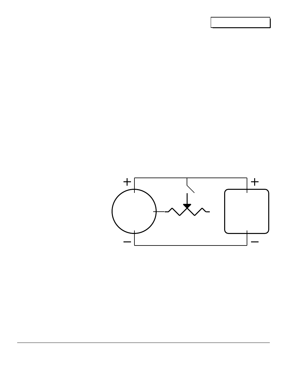
All alternator controls work by limiting the amount of power
supplied to the alternator's rotating magnetic field. All
alternator control starts with controlling the field's energy.
Car Voltage Regulators
Car voltage regulators will not work well in deep cycle
applications. The regulator makes its decisions based only on
the system's voltage. This is fine with the average car battery
which is cycled to less than 1% of its capacity before being
refilled. The deep cycle battery, however, is
almost empty when it is recharged. The car
voltage regulator attempts to instantly bring the
system's voltage to about 14 volts. A 12 volt
deep cycle lead-acid battery will not reach a
voltage of 14 volts until it is almost filled. The
net result is that the car regulator dumps the
entire output of the alternator into the batteries
until they are full. This is most always too
much energy too fast for a fully discharged
battery.
To compound the problem, the car regulator's
voltage limit is set too low for deep cycle
service. This low voltage limit means that the
batteries are charged too slowly when they are
almost full, resulting in many extra hours of
generator operation to totally fill the battery
pack. Since the car regulator is set at about
14 volts, we are unable to raise the system
voltage up to over 16 volts for the essential
equalizing charges.
Resistive Field Controller
The simplest and cheapest form of alternator control is to use
resistance to limit the amount of energy that is fed to the
alternator's field. The idea is very simple, insert resistance
between the battery's positive pole and the wire feeding the
alternator's field. Resistance in the neighborhood of 2 to 25
ohms works well. Adjust the resistance until the charge rate
into the battery is between C/20 and C/10. The less the
resistance in the field line, the higher the amperage output of
the alternator. Originally we used a nichrome wire heating
element from an old electric stove as a resistor. We used
more or less wire (hence more or less resistance) with a wire
clip lead. It worked fine. A better resistor to use is a 0 to 25
ohm rheostat (an adjustable power resistor) rated at least 25
watts. This allows smooth adjustment of the alternators output.
Figure 2 shows the wiring hookup for a resistive field
controller.
Using resistive field control produces a system which is current
regulated only. The resistive circuit does not provide any form
of voltage regulation. When the batteries are full the system
voltage can get very high, over 16 volts. Voltage this high can
damage 12 VDC appliances that are on line at the time. The
highest voltage for most 12 volt equipment is 15 volts. If you
are using resistive field control, be sure to monitor the system's
voltage and reduce the current output of the alternator to keep
the system voltage under 15 volts when appliances are being
used.
Mk. VI Electronic Field Controller
We eventually solved the problem of control by designing a
series of electronic field controllers that regulate both the
amperage and the voltage of the alternator. With this
electronic field control, we simply set the desired charge rate,
and set the system's voltage ceiling. The battery is recharged
at a constant rate until it is full. When the batteries are full, the
voltage limit predominates and the system is voltage regulated,
thereby protecting the batteries from overcharging. And also
protecting all electrical equipment on line. The amperage
output is adjustable from 0 to the full rated output of the
alternator. The voltage limit is adjustable from 13.5 volts to
16.5 volts.
For the intrepid electronic builder, this electronic field
controller's schematic is included. This field controller uses off
the shelf parts available at Radio Shack. Printed circuit
boards, kits, and completed field controllers are available from
the Electron Connection Ltd., P.O. Box 442, Medford, Oregon
97501. Complete installation and operating instructions are
included. Write for more info.
Motorized Sources for Equalizing Charges
The motorized source is the best type to use for the equalizing
charges. Its voltage output is capable of being adjusted to
over 16 volts in order to accomplish the equalizing charge.
The motorized source is capable of delivering a C/20 rate of
charge for the least 7 continuous hours necessary for battery
equalization. Remember the batteries must already be full
before the equalizing charge is started.
Users of solar and wind systems should consider constructing
AUTO
ALTERNATOR
Batt
Ground
Battery Negative Pole
Battery Positive Pole
12 VOLT
BATTERY
PACK
25
Ω
25W. RHEOSTAT
Field
Input
Fig. 2- Resistive Field Controller
25
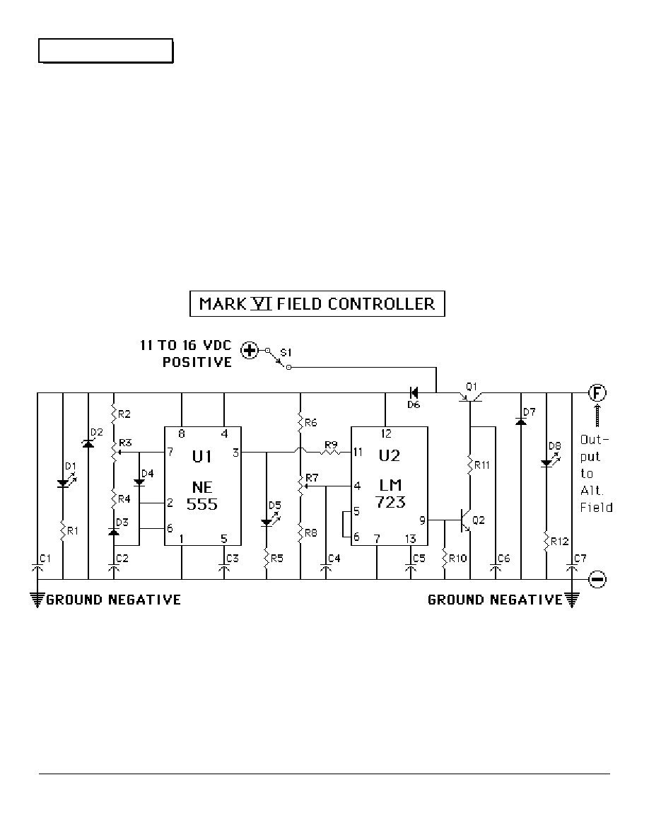
Engines
Home Power 2 January 1988
a lawnmower powerplant just to equalize their batteries. The
very nature of wind and solar energy makes it very difficult to
equalize the batteries without such a motorized power source.
This generator makes excellent backup power for times when
Mother Nature isn't cooperating with our energy demands.
Integrated Circuits
U1- NE555 Timer, in 8 pin DIP
U2- LM723 Voltage Regulator, in 14 pin DIP
Transistors
Q1- MJE 2955, or any PNP with Ic>5 Amps.
Q2- 2N2222A
Diodes
D1- Red LED
D2- 18 Volt Zener
D3 & D4- 1N914
D5- Yellow LED
D6- 1N4004
D7- 1N1202A, or any 3+ Amp. diode
Resistors
R1, R5, R9, & R12- 1 K
Ω
R2- 4.7 K
Ω
R3- 100 K
Ω
Potentiometer
R4- 4.7 K
Ω
R6- 3 K
Ω
R7- 1 K
Ω
Potentiometer
R8- 3.3 K
Ω
R10- 4.7 K
Ω
R11- 100
Ω
, 10 Watts
All resistors 1/4 Watt & 5% unless
otherwise noted.
Capacitors
C1 & C7- 0.1µf
C2- 0.047 µf
C3, C4, & C6- 0.01 µf
C5- 0.0001 µf
All capacitors are 25 Volt rated
All commercial rights reserved by Electron
Connection Ltd. Any commercial use of this
circuit is prohibited without express written
permission from Electron Connection Ltd.
Homebuilding of single devices, by the end
user, is approved and encouraged without
written permission.
26
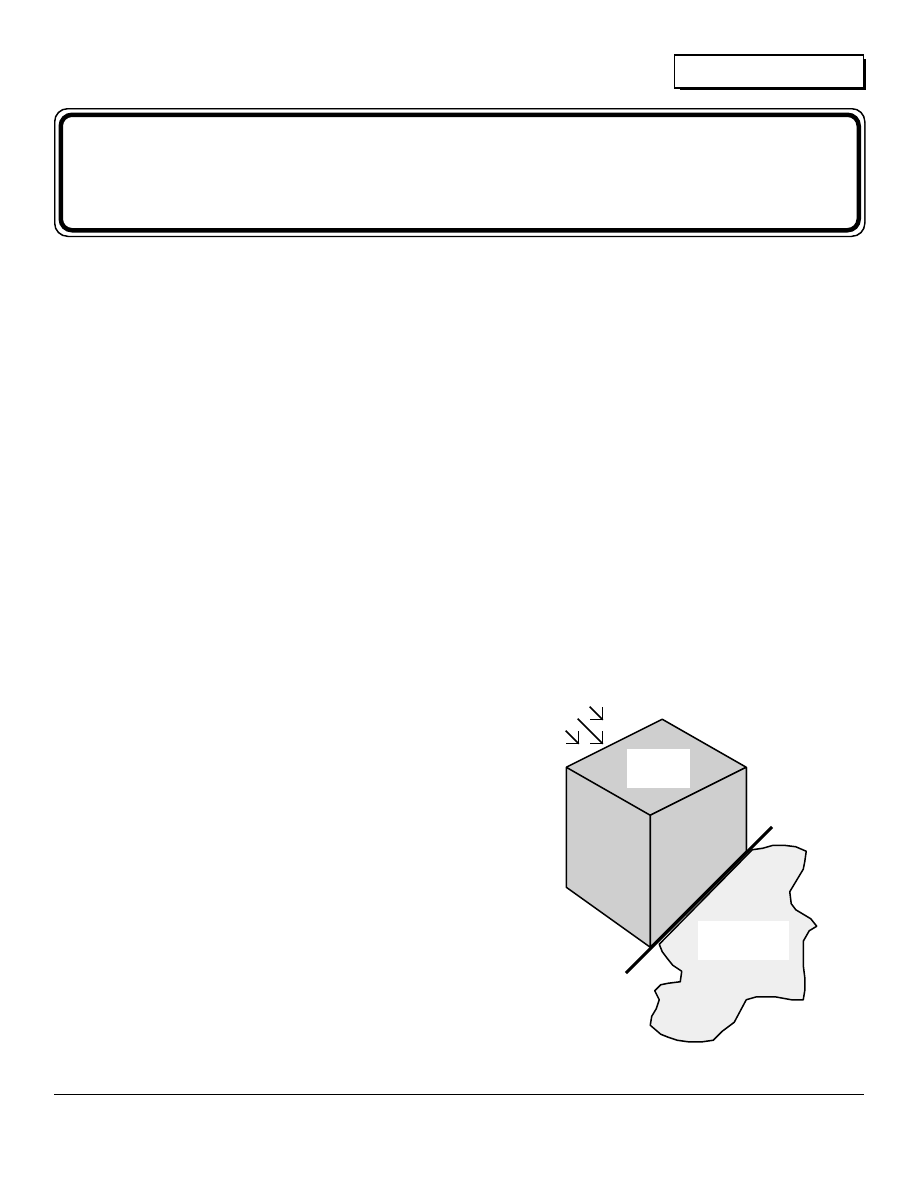
Heat
Home Power 2 January 1988
The Fireside
by
Don Hargrove
o understand our increasing need for renewable energy, we must know that our future lies not
in the hands of those who abuse, but in the hands of those who efficiently use our valuable
resources.
In this and future articles I will discuss heat: its definition and
its use. By being aware of this basic technology, we can gain
a working knowledge of heat's daily application in various
systems.
WHAT IS HEAT?
Heat is a form of invisible energy. Only the work that heat
does can be seen. For instance: when the gas in your
automobile engine is ignited, the burning gases expand. This
expansion causes a release of heat (energy), which in turn
causes work to be done. This work then becomes mechanical
energy.
TEMPERATURE AND HEAT
All matter consist of molecules in motion. This motion is
defined as internal energy or heat. The amount of this internal
energy depends upon how rapidly the atoms or molecules are
moving. The faster these particles are moving, the hotter the
object is and the higher amount of internal energy it contains.
TEMPERATURE is an indication of an object's internal energy.
A thermometer measures this in degrees; Fahrenheit and
Centigrade (Celsius) being the two most common scales. The
temperature of an object determines if that object will gain or
lose internal energy. Heat always flows from a hotter object to
a colder one. This is a temperature "hill". Like water, heat
flows downhill. The greater the difference in temperature
between two objects, the steeper the hill, and the faster the
heat will flow between the two objects. The hotter object is
giving up some of its internal energy to the colder one. Given
enough time, these two objects will equalize their temperature.
It is important to remember that heat and temperature are not
the same thing. Temperature is an indication of the amount of
internal energy and heat is the transfer of this internal energy
between two objects. Heat is measured in two basic units:
BTUs (British Thermal Units) and calories. One BTU is the
amount of heat needed to raise one pound (approximately one
pint) of water one degree Fahrenheit. One calorie will raise
one gram (0.035 ounce) of water one degree Centigrade.
These units are calculated at sea level atmospheric pressure
(one atmosphere).
Heat and temperature tell only part of what is happening. Let's
look at what happens to an object when heat flows into it. As
the heat raises the internal energy of the object, its molecules
start moving more rapidly. The more heat an object has, the
more disorderly its molecular pattern becomes. Science
defines the amount of disorder in a system as entropy.
Heat flowing from an object will decrease its internal energy, its
amount of molecular disorder, and thus its entropy. The
temperature of the object will usually change, according to the
direction of heat flow, but not always. When an object changes
its physical state (from solid to liquid to gas), energy, disorder,
and entropy change, but the temperature will remain the same
until the particular change of state is completed.
As an example of heat content versus temperature see the
following graph. It shows how many BTUs are required to raise
one pound of water from -4°F to 212°F at sea level (1
atmosphere). For comparison, kilocalories (1000 calories=1
kilocalorie) are also given. It takes 1 calorie to raise the
T
ICE
WATER
Orderly
Molecular
Pattern
Disorderly
Molecular
Pattern
Heat
In
27
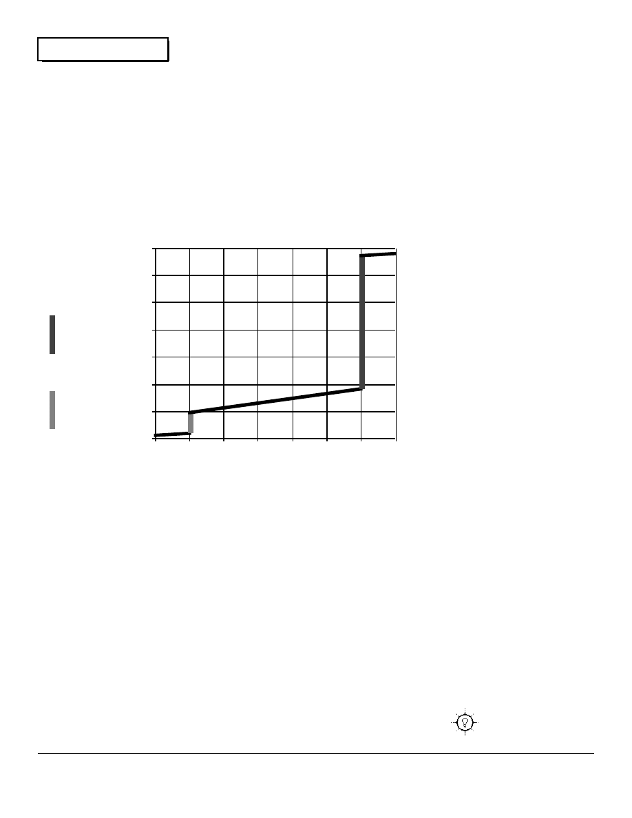
Heat
Home Power 2 January 1988
temperature of 1 gram of water 1 degree Centigrade.
454 grams = 1 pound
454 calories = 1.8 BTUs
1.8/454 = 0.00397 BTUs in 1 calorie
454/1.8 = 252 calories in 1 BTU
252/1000 = 0.252 kilocalories in 1 BTU
Note that there is no change in temperature until there is a
change of state. Ice stays at 32°F until it is completely melted.
To accomplish a complete change of state from ice to water
requires 144 BTUs of latent heat. Now that the ice has
completed its change to water, each added BTU will cause a
rise in temperature of 1°F, until the water reaches its boiling
point of 212°F. At this point, 972 BTUs are required to
complete another change of state from water to steam. The
temperature, however, remains at 212°F until all the water has
become steam. Once again, the temperature will start rising
1°F for each BTU added. There is one added requirement for
the temperature of the steam to continue rising. Steam is
water in its gaseous state. Were it not contained, this "water
vapor" would simply expand and eventually recondense
elsewhere. Therefore a high pressure vessel is needed to
contain this expansion. Now, any addition of BTUs to the
vessel containing the steam will cause a corresponding rise in
temperature. The water molecules within this steam now have
a very high internal energy and they are moving at an
extremely high rate of speed.
HOW HEAT TRAVELS
Heat passes from one place or object to another by three
methods.
CONDUCTION is the movement of heat through a material
without carrying that material along with the heat (that is,
without changing the conducting materials physical structure).
Example: Heat a copper rod on one end only. The copper
molecules in the heated end will start vibrating due to the
increased internal energy. These vibrating molecules will
strike unheated copper molecules next to them, transferring
heat. This chain reaction will continue until the entire rod is
heated. Note that the copper molecules themselves have not
moved. It is only their internal energy bumping against each
other causing the heat transfer.
CONVECTION is the transfer of heat by movement of heated
material. Example: the suns rays hit the earth and heat it. The
air next to the ground is heated by conduction. This heated air
expands, becomes lighter, and rises. Cooler air, being denser
and therefore heavier, will flow downwards to replace the
lighter air. This process is called
convection and the flow of heated air
upwards is known as a convection
current. Convection occurs in liquids as
well: the bottoms of oceans, lakes, and
rivers are the coldest.
RADIATION
Conduction and convection transmit
heat by particle vibration. Heat can also
move through a vacuum which contains
no matter. Heat can move as radiant
energy. When this radiant energy
strikes an object, the particles in that
object speed up. An example of radiant
heat, or infrared as scientists call it, is
the heat striking the earth from the sun.
Understanding basic heat definitions and
the different ways heat moves will help
us to better and more efficiently use it.
In following issues, I will show you
practical applications of the rules of
heat. I will compare methods of using
and saving BTUs. Look forward to
reading about solar heating,
thermostats, stack robbers, methods of
heating living space and water, BTU
content comparisons of differing
materials and lots more. Until then--
stay warm, hopefully as efficiently as
possible.
0
200 BTU
50 kcal
400 BTU
101 kcal
600 BTU
151 kcal
800 BTU
202 kcal
1000 BTU
252 kcal
1200 BTU
302 kcal
1400 BTU
353 kcal
-4°F
-20°C
32°F
0°C
68°F
20°C
104°F
40°C
140°F
60°C
176°F
80°C
212°F
100°C
248°F
120°
C
CHANGE
IN
THERMAL
ENERGY
TEMPERATURE
Energy, Temperature & Changes of State for One Pound of Water
from
Water
to
Steam
from
Ice to
Water
28

Things that Work
Home Power 2 January 1988
Things that Work
Home Power tests the Trace Model 1512, 1.5kW. Power Inverter
Test Environment--
We tested the 1512 at our site located about 12 miles from any
commercial utilities. This place has been totally powered by
alternative energy since 1976. Photovoltaics and motorized
generators (both 12 VDC and 120 VAC) are the power
sources. We hooked the 1512 inverter to 2 Trojan L-16W
batteries (350 ampere-hours at 12 volts) for the test period.
The 1512 was wired to the batteries with 0 gauge copper
cables with a combined length of less than 6 feet. The inverter
is used to power a variety of test equipment, computers,
printers, power tools, kitchen appliances, and some lighting.
The 1512 was constantly monitored by a DC powered
oscilloscope (fully isolated from the 1512's output by its own
internal battery power supply), a DVM, and an analog
expanded scale AC voltmeter during the entire testing period of
three weeks. Testing was conducted by Richard Perez.
Packing, Installation Instructions, and Owner's Manual
The unit was packed very well and survived UPS shipping.
The shipping container is first class. We first turned our
attention to the installation instructions, and operator's manual.
It is well written, very thorough, and has a folksy flavor that is
refreshing. The short form for immediate hookup is a very
good idea for impatient customers. All the instructions are
clear and concise. No one should have any trouble installing
or operating the model 1512. All that is necessary is to read
the manual.
The manual is very detailed in comparison with those of other
inverter manufacturers. It may be a little too technical for
some, but it is good to see this information available to the
users. The discussion of the various types of loads and how
they function on this inverter is very good, and will help
non-technical users understand such things.
Inverter Operation
The 1512 powers inductive loads better than any inverter we
have ever used. Regardless of size or type of load (we tried all
kinds), the inverter was very consistent in its output waveform.
We saw on the oscilloscope that we could not get the inverter's
waveform to go out of the modified sine wave mode. This is
amazing and almost unique. The Trace is very different from
some inverters, which put out a wide variety of glitchy
waveforms on inductive loads (especially small ones). The
Trace 1512 inverter powered inductive loads such as
fluorescent lights, stereos, TVs, satellite TV systems, sewing
machines, computers, and motors better and quieter than
many other modified sine wave inverters.
Our inductive AC equipment happily consumed the power
made by the 1512. One very dramatic case was our computer
equipment. This computer equipment has had problems with
overheating when powered by other inverters. It ran much
cooler on the 1512.
The Trace inverter is among the most efficient types we have
tested. The 1512 met Trace's specs for efficiency. The 1512
inverter produced noticeably less heat when powering large
inductive loads. For example, we used a large 720 watt
vacuum on the inverter. When powered by another inverter
this vacuum began serious overheating after only 20 minutes
of continuous usage. The inverter itself was also very warm.
When the vacuum was run on the Trace 1512, neither it or the
1512 showed any appreciable heating after over 2 hours of
continuous operation.
The 1512 has excellent voltage regulation and is within Trace's
specs. Regardless of load size, load type, temperature, and
battery voltage, the 1512 did not vary over 2 volts (measured
by us) in its AC output voltage. We tested the inverter on input
voltages from 11 to 15.3 VDC. Temperature ranged from 10°
C. to 40° C. Loads ranged from 25 watts resistive to 1.2 kW.
inductive. Trace has really accomplished a great deal in the
area of voltage regulation. Trace's digital approach to inverter
design has produced an incredibly stable inverter. We were
not able to measure any deviation from 60 cycles in all our
testing. This is a big plus for anyone powering TV, video
equipment, or audio equipment from an inverter.
The 1512 met Trace's specs. for power output. We repeatedly
tried to overload the Trace inverter, but we couldn't kill it. The
1512 protected itself from any damage due to overloading. We
tried resistive and inductive loads up to 3kW, with starting
surges over 10kW. In the past, inverters would not survive
being so grossly overloaded.
Battery Charger Operation
The battery charger was a very pleasant surprise. Not only is it
easily user programmable, but its range of operation is much
greater than anything else available. The 70+ Ampere current
output of the 1512's charger is nearly twice as powerful as any
comparable unit. The battery charger's voltage output can be
set high enough to fully recharge deep cycle batteries. The
Trace 1512 is the only inverter/charger we've seen that can
effectively cycle the batteries; it is unique.
The Trace is the best for operation with a motorized generator.
The 1512 will recharge the batteries faster than any other type
of inverter/charger we've ever seen. This results in less
generator operating time, and greater fuel economy. The
programmable nature of the charger makes overcharging or
too rapid charging of the batteries impossible. The 1512's
current output was very constant over the entire recharging
voltage range of our test batteries. Inverter to generator
automatic changeover is smooth and positive. The Trace 1512
has the best built-in battery charger in the industry.
On the down side...
It was very difficult to find anything to complain about with the
Trace 1512. The only feature we didn't like was the inverter's
audio buzz. This audio noise is loud enough that the inverter
should be located where no one will have to listen to it. A little
noise is a very small matter in comparison with the inverter's
many fine points.
Conclusion
29
Things that Work
Home Power 2 January 1988
The Trace 1512 is one of the finest modified sine wave inverter
available. We found that it meets all of Trace's specifications.
It is as far ahead of most other inverters as a Corvette is from a
Model T. The 1512 is the first inverter to combine digital
technology with ease of use, efficiency, and sheer toughness.
The list price of $1,310. (with optional charger) is in line with
the 1512's superb performance. We are recommending the
Trace 1512 as an excellent buy. You can get more info on the
1512 from Trace Engineering Inc., 5917 195th NE, Arlington,
WA 98223, or phone 206-435-8826.
30
WIND POWER SYSTEMS
12 VDC to 120 VDC Battery charging, Heating,
Pumping, AC Interface
PHOTOVOLTAIC SYSTEMS
36 VDC GARDEN TRACTORS
attachments & accessories
SOLAR AIR 7 WATER HEATERS
DC ELECTRICAL EQUIPMENT
Grain mills, Fans, Relays, Motors,Water heating elements,
Propane & Sun Frost refrigerators, Inverters
USED EQUIPMENT
DIATOMACEOUS EARTH
HYDROGEN PEROXIDE
information $2.
since 1975 catalog $3.
KANSAS WIND POWER
ROUTE 1, DEPT. HP
HOLTON, KS 66436
phone: 913-364-4407

Batteries
Home Power 2 January 1988
Build an Accurate Battery Voltmeter
by
Alex Mason
he battery article in last month's Home Power gave information and graphs that determine a
battery's state of charge using voltage measurement. Many readers wrote in and asked for
details about accurate voltage measurement for their systems. So here is a homebrew
project-- a simple to make, accurate voltmeter that can be left on line all the time.
Voltage vs. State of Charge
The state of charge (SOC) of a lead acid battery can be
determined by measuring its voltage. Details and graphs
about the relationship between SOC and voltage are in Home
Power #1. If you don't have a copy of HP#1 to refer to, then
please write Home Power (POB 130, Hornbrook, CA 96044)
and we'll send you a copy of Home Power #1, postpaid, for $2.
Analog vs. Digital Metering
Without any doubt digital metering is more accurate and easier
to read than analog metering. Digital metering reads out in
numbers (either LCD or LED like your digital watch), while
analog meters use the old standard electromechanical meter
movement (like the fuel gauge in your car).
If you wish to go to the expense of a digital multimeter (DMM),
then I recommend the Fluke Model 77 which costs about $145.
It is very accurate (0.3%) and well worth the money because it
is so versatile. We use one for all sorts of metering jobs. The
problem with using DMMs for battery measurement is that they
use small internal batteries to power the meter. This is OK for
most uses, but in an AE system we need to have a readout on
our battery's voltage ALL the time, 24 hours a day. This
means that the expensive DMM is tied to a single purpose, and
constant operation wears out the DMM's internal, expensive,
batteries very quickly. What is necessary is an accurate
battery voltmeter that can be left on line all the time, and is
powered by the large batteries in the AE system, not by small
internal batteries.
Expanded Scale Analog Battery Voltmeter
This metering circuit was developed by Electron Connection
Limited for its customers. While Electron Connection
encourages you to build this circuit for your own use, we do
reserve all commercial rights to this design. The idea is to use
an analog dc ammeter in a circuit that will accurately measure
the batteries voltage. This circuit produces an expanded scale
voltmeter. Most analog voltmeters start reading a 0 volts. This
is really a waste for battery systems as a lead acid battery will
have about 10 to 11 volts even when just about empty. So the
portion of the meter's scale between 0 and 10 volts is not used.
Wasting this portion of the meter's scale decreases the
resolution and thereby the accuracy of the meter. This circuit
allows the meter to start reading at 11 volts and to display full
scale at 16 volts (a very fully charged battery while still under
charge). This is called an expanded scale, and makes the
meter much more accurate to use.
All the components for this metering project are available at
most Radio Shack stores, or from just about any electronics
supply house. Cost of the parts should be between $20. and
$40., depending on your hardware sources. Construction time
is about 1 hour for an experienced assembler. This circuit is
powered by the battery under measurement, and never
requires the use of small batteries to power the meter.
We don't have space here to give an electronics primer for
those not familiar with electronic construction. What we do
offer is the schematic for the circuit on the next page. If you
can't figure out how to build this meter from the schematic,
then please seek out an electronics person who can aid you.
For those wishing the meter already constructed and
calibrated, please send $75. to Electron Connection Ltd., POB
442, Medford, OR 97501, and allow six weeks for delivery
because we hand build each and every one to order.
Electronic Nitty-Gritty
This circuit uses a 1 mA. DC Ammeter as an expanded scale
voltmeter. The meter has its ground elevated to 11 volts by the
use of an LM 723 voltage regulator in shunt mode. This makes
the meter very accurate as there are no series semiconductors
in the measurement circuit. Full scale reading and the 11 volt
ground level are both adjustable by using the potentiometers in
the circuit. R1 is the adjustment for the shunt regulator. Adjust
R1 until Test Point 1 (TP1) is at 11 Volts. Then adjust R2 until
the meter reads the battery's voltage at the time. Use an
accurate DMM to calibrate this circuit.
Average power consumption of this meter is about 5 milliWatts.
When on line 24 hours a day, power consumption is less than
0.1 Watt-hours per day. This meter is super-efficient and can
be left on line all the time with a minimum of power
consumption.
T
31
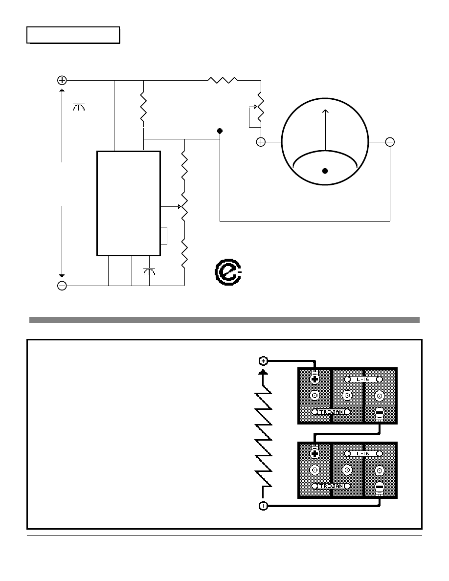
Batteries
Home Power 2 January 1988
11 to 16 VDC Expanded Scale Battery Voltmeter
32
TROJAN BATTERIES
America's most dependable
batteries since 1925
Makers of the famous L-16W Battery.
THE most cost effective energy storage for
Alternative Energy Systems.
Trojan Batteries, Inc.
1395 Evans Avenue
San Francisco, California 94124
(415) 826-2600
1 K
Ω
,
1/2W.
TP1
10 K
Ω
R1
2 K
Ω
22 K
Ω
.001 µf
.01 µf
3.3 K
Ω
R2
2 K
Ω
12
11
5
4
6
7
9
13
LM 723
1 mA. DC Ammeter
All resistors 1/4 W. unless otherwise noted
All capacitors 25 volt rated
All Commercial Rights Reserved by
ELECTRON CONNECTION LIMITED
Battery
Input
11 to 16
Volts
DC

Basic Electricity
Home Power 2 January 1988
Low Voltage Wiring Techniques
by
Alex Mason
n many AE systems it is efficient and inexpensive to use the low voltage DC electricity directly
from the batteries. Here is all the info you need to get this energy down the line, to the job, with a
minimum of loss.
Resistance- The BIG Problem
Resistance is the impedance to electron flow within any
material. All electrical wiring, connections, plugs, and switches
have some electrical resistance. This resistance causes
losses within the entire low voltage circuit. The idea with low
voltage wiring is to minimize this resistance, and thereby the
associated losses. The reasons for this are: 1) we don't want
to waste power, and 2) 12 VDC from the batteries is already
low enough in voltage, we can't afford to lose any more than
necessary transferring this energy from the batteries to the
load. Low voltage at a load causes substandard performance.
It means slow motors, dim lights, and generally poor appliance
operation.
The Entire Circuit
Every electrical appliance in a system must have a complete
circuit to the batteries. Consider the lightbulb on the ceiling.
The electrons that power this lightbulb follow a very specific
path to accomplish their purpose. Every electron originates at
the battery's negative pole. From this pole it makes a journey
through the wiring, connections, and switch(es) to the lightbulb.
After any given electron passes through the lightbulb it makes
its way through the wiring, connections, and switch(es) back to
the positive pole of the battery. This path is set. Every
electron must make this entire journey in order to do work.
Every electron must pass through each circuit element (piece
of wire, connection, plug and/or switch) in order to complete
the circuit. In technical terms, what we have here is a series
circuit. A series circuit means that there is only one path
available to the electrons.
A series circuit is like a chain: it is limited by its weakest
element. The total resistance of a series circuit is the sum of
all the resistances within that circuit. Each individual element
within the circuit introduces losses based on its resistance.
The primary lesson to be learned here is that ANY (and it only
takes one) high resistance element within the circuit will make
the ENTIRE circuit's resistance high enough to be
unacceptable. Every element within the circuit must have low
resistance for the entire circuit to have low resistance. It only
takes one piece of undersized wire, one funky connection, or
one wornout switch to make the loss of the entire circuit
unacceptable. So, in low voltage circuits we must consider
every element in the circuit. It is not good enough to use
properly sized wire if it is connected improperly, or if the wire is
connected to a switch (or any other single circuit element) with
high resistance. Attention to the details of the circuit is
essential. Let's look at the individual elements that make up
the circuit.
Wiring
The size of the wire (or gauge) feeding the load is critical. Wire
size is specified in any application by considering two factors:
1) the amount of current that the wire transmits, and 2) the total
wire length (both conductors) from the battery to the load.
Ohm's Law (see Home Power #1 if this is a new idea for you)
gives us the relationship between voltage, current, and
resistance in an electrical circuit.
E = IR
Wiring makes up many of the elements in a circuit. Larger
sizes of wire have more copper in them, and hence lower
resistance. Wire size is specified by a gauge number. The
lower the gauge number, the larger the diameter of the copper
wire, and thereby the lower its resistance. The actual
resistance per 1,000 feet of various copper wire gauges is
detailed in Table 1, the Copper Wire Table. We encourage
you to use only copper wire in your AE system. Aluminum wire
has greater resistance (about twice for the same cross
sectional area) and is virtually impossible to interconnect
without higher resistance connections. If you don't think so,
then try soldering an aluminum wire sometime.
From the Copper Wire Table, we can calculate the resistance
of any particular piece of wire. The resistance per foot times
the number of feet gives us the total resistance of a length of
wire. When estimating the resistance of wiring be sure to
include BOTH conductors, i.e. if an appliance is 100 feet from
the battery, then the total wiring length is 200 feet (there are
two wires actually, each one 100 feet long).
If we know the amount of current being consumed, the
resistance per foot of any given wire gauge, and the length of
the total wire in the circuit, then how do we determine the
actual gauge of wire we should use? The answer is
determined by exactly how much loss we find acceptable. In
general, consider a 5% loss to be the maximum acceptable
(2.5% is better). If we are using 12 VDC, then 5% voltage loss
is 0.6 volts (2.5% is 0.3 volts). Consider the following equation
to specify exactly which wire gauge to use for any given
application.
R = Resistance expressed in Ohms (
Ω
) per 1000 feet.
E = Maximum allowable voltage loss in the wiring, in Volts.
I = Amount of current flowing through the circuit, in Amperes.
L = The length of wire in the complete circuit, in feet.
This equation gives us a value in Ohms per 1,000 feet. Simply
find the copper wire gauge size that has LESS than this
amount of resistance per 1,000 feet, and you've found your
wire gauge size.
I
33
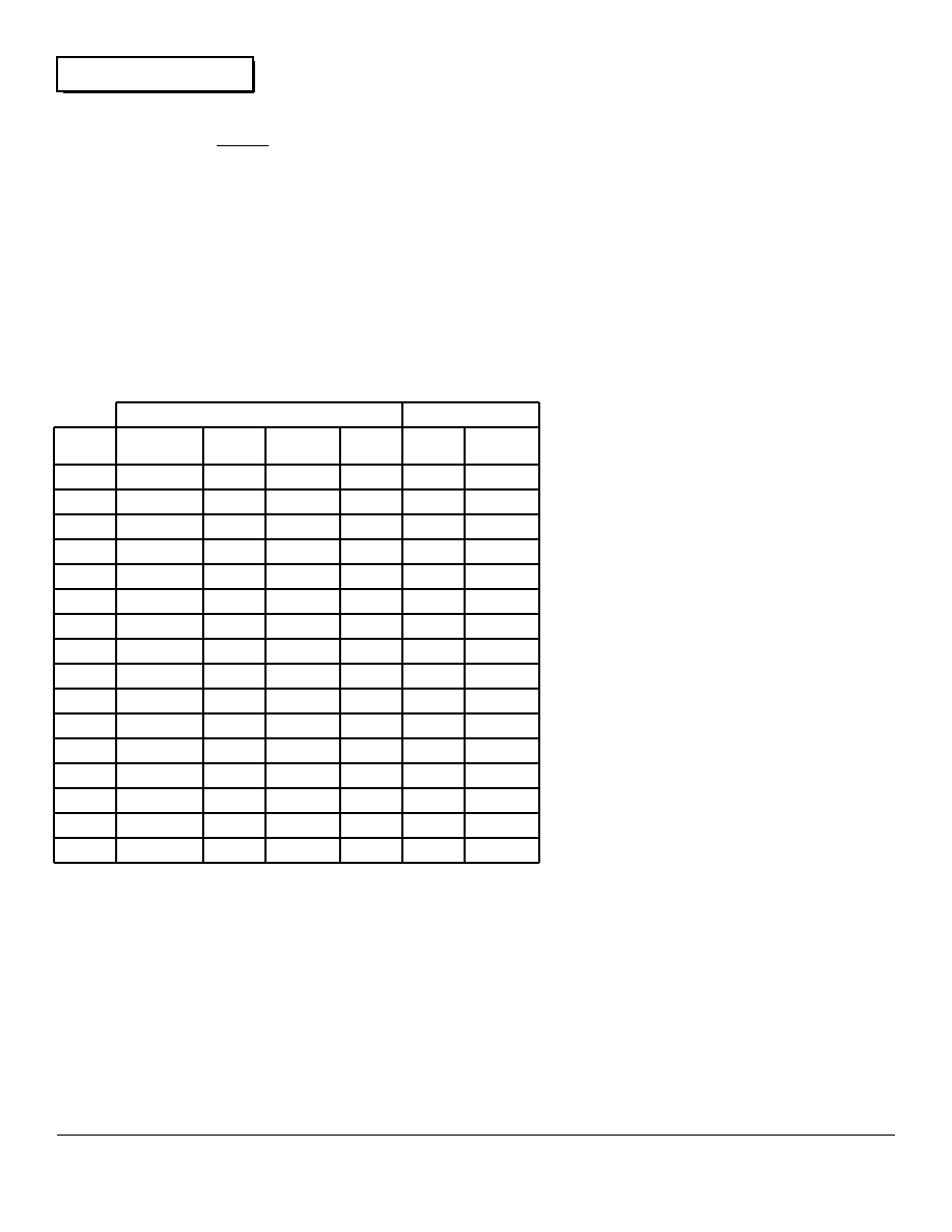
Basic Electricity
Home Power 2 January 1988
Consider a PV array that produces 12 amperes. This array is
located 100 feet from the batteries. What gauge size of wire
should be used to keep the voltage loss in the wiring to less
than 0.6 volts? Well, there is 200 feet (two conductors,
remember) of wire in the circuit, and a current of 12 amperes
flowing. The equation above gives us a maximum resistance
of the wire as 0.25
Ω
per 1,000 feet. By consulting the Copper
Wire Table, we find that 4 gauge wire has a resistance of
0.2485
Ω
per 1,000 feet. Since this is less than the
0.25
Ω
/1,000 ft. the equation generated, 4 gauge wire is the
size to use.
Get on the Bus
In reality houses and systems contain many circuits. Some of
these circuits are straight series types as mentioned above.
Others are parallel circuits, where two or more loads are
supplied electricity by the same piece of wire. The
mathematical analysis of all these circuits can become very
complex. A way around this complexity is to use a standard
wiring technique that is very effective in low voltage
systems--The Bus.
A bus is a heavy set of wires used to carry current to other
smaller wires which eventually feed the loads. The battery's
energy can be distributed by two heavy wires (usually 2 or 4
gauge) that run the entire length of a building. Smaller 8 or 12
gauge wires are soldered to this bus to supply the individual
loads. This structure is similar to the skeleton of a fish, a
heavy spine with smaller bones attached to it. This technique
allows low voltage energy to be distributed with a minimum
loss. Ideally, each load should have its own individual feeder
wires soldered to the bus. All feeder wiring lengths should be
as short as possible. This technique also allows the use of
standard wiring components like switches, plugs and sockets,
which will not accept the huge diameter of 2 or 4 gauge wire.
Solder Connections When Possible
In standard 120 VAC house wiring, it is very unusual to solder
connections. In low voltage systems, soldered connections
should be made wherever possible. All wire to wire
connections should definitely be soldered.
Mechanical connections using wire nuts are OK for
higher voltage systems, but these connections have
too much loss for low voltage systems. Soldering
assures a permanent, low resistance connection.
Mechanical connections gradually oxidize over a
period of time. While copper is a very good
conductor of electricity, copper oxide is not.
Gradual oxidation in mechanical connections
increases their resistance. Remember, a single
high resistance connection within the circuit will
make the resistance of the entire circuit high. So
get into solder. Once you've made a good solder
joint, it's good forever.
Switches, Sockets & Plugs
The switches, sockets and plugs in a low voltage
systems must have low loss (i.e. low resistance) just
like every other component in the system. We can
assure low loss in these components by two
techniques. The first is to purchase specialized low
voltage switches, sockets and plugs. These
components have more massive contacts, with
higher contact pressures, to deliver low resistance.
These components are expensive and hard to find.
Another technique is to use standard 120 VAC
components and to derate them. Derating means
that we run only a portion of the rated current
through the component. Derate 120 VAC switches,
sockets and plugs by at least a factor of three.
Consider a plug or a switch that is rated to handle
15 amperes of current at 120 VAC. If we run 5
amperes or less (15/3) through the component, then
its losses will be acceptable. Derating allows use of
the more commonly available, higher resistance,
components by reducing the current we run through them.
In any case, keep the use of switches, sockets, and plugs to a
minimum in a low voltage system. If an appliance can be
soldered to its power wiring, then this should be done. If you
are using standard 120 VAC sockets and plugs in low voltage
systems, be sure to use the 3 conductor types. The
three-prong type of sockets and plugs are polarized. They will
only connect in one fashion. If they are wired with proper
polarity to start with, it is impossible to plug in a polarized low
voltage appliance backwards. This can save electronics,
fluorescent lights and other DC appliances from being
connected backwards and destroyed. The third conductor on
these plugs and sockets can also be used to carry current.
R =
E
(1000)
I L
0000
000
00
0
2
4
6
8
10
12
14
16
18
20
22
24
0.04091
0.06180
0.07793
0.09827
0.1563
0.2485
0.3951
0.6282
0.9989
1.588
2.525
4.016
6.385
10.15
16.14
25.67
20400
16180
12830
10180
6400
4025
2531
1592
1001
629.6
396.0
249.0
156.6
98.50
61.95
38.96
0.1608
0.2028
0.2557
0.3224
0.5127
0.8152
1.296
2.061
3.277
5.211
8.285
13.17
20.95
33.31
52.96
84.21
6219
4932
3911
3102
1951
1227
771.5
485.2
305.1
191.9
120.7
75.90
47.74
30.02
18.88
11.87
460.0
409.6
364.8
324.9
257.6
204.3
163.0
128.5
101.9
80.81
64.08
50.82
40.30
31.96
25.35
20.10
11.68
10.40
9.266
8.252
6.544
5.189
4.115
3.264
2.588
2.053
1.628
1.291
1.024
0.8118
0.6438
0.5106
WIRE
GAUGE
OHMS PER
1000 FEET
FEET/
OHM
OHMS/
KM.
METERS
PER
Ω
MILS
MM.
RESISTANCE
DIAMETER
TABLE 1- THE COPPER WIRE TABLE
34

Basic Electricity
Home Power 2 January 1988
So, are you interested in a FREE
LUNCH? Will you go for it?
"What is anti-entropic?", you ask. Well,
here's one definition: An anti-entropic
process is one which creates more
energy than it consumes. There are
three basic strategies which may provide
a path to the free lunch.
1) Create a feedback process to continually
regenerate the source, using only a portion of the output. This
is a source multiplier.
2) Create a process that is more than 100% efficient. This is a
direct energy multiplier.
3) Find an infinite and undiminishable power source. This is
equivalent to finding God in the physical universe.
These paths are possible and can be implemented through the
proper understanding and use of leading edge physical
theories in the following areas:
1) The basic structure of matter & energy.
2) The nature of gravity & magnetism: how they interrelate.
3) Space & time.
Even today the first short-term approaches to the free lunch
are being taken. This will hopefully lead to an era of
unparalleled abundance.
Go with the Wizard. Onward into the Future!
Simply wire this third connector (normally used for the ground
in AC systems) in parallel with either of the power wires. This
even further reduces the overall resistance of the plug and
socket combination.
Low voltage wiring is not difficult. It only requires that you cozy
up to Ohm's Law. If you can work with the concepts of
resistance, voltage and current, then you can apply these
concepts in your system. Low voltage wiring requires attention
to detail. Consider every element in the circuit. If you keep the
individual losses within components to a minimum, then the
overall system will take care of itself.
the Wizard
35
Basic Electricity
Home Power 2 January 1988
Home Power 2 January 1988
36
Home Power Display
Advertising Rates
Full Page- $1,200
Half Page- $672
Third Page- $480
Quarter Page- $377
Sixth Page- $ 267
Eight Page- $214
We are desktop published (via Macintosh
computers) and can setup and layout your
advertisement if you so desire. Camera
ready display advertising is also accepted.
Advertising deadline is the 10th of a month
for the issue distributed on the 20th of that
month.
We can handle all types of photographs,
including full color.
We can position your display advertisement
wherever you wish in the magazine.
Long term display advertising is discounted,
so buy ahead and save.
Contact Glenda Hargrove at 916-475-3179
for further details and a media kit.
Home Power
Magazine
Back Issues
$2. each while they last, shipped first
class mail in an envelope.
WRITE
Home Power Magazine
POB 130
Hornbrook, CA 96044
International Susbscriptions to
HOME POWER
due to the high cost of international mailingand packaging
requirements, we must charge for copies of Home Power that
are mailed anywhere that doesn't have a US ZIP CODE.
YEARLY INTERNATIONAL RATES:
Mexico or Canada: Air- $24. Surface: $21.
Central America, Bahamas, Bermuda, Columbia and
Venezuela: Air- $32. Surface: $ 23.
South America ( except Columbia and Venezuela), Europe,
North Africa: Air- $40. Surface- $23.
Asia, Australia, New Zealand,Pacific Ocean Islands, Africa
(other than North Africa), Indian Ocean Islands, and the Middle
East- Air $49. Surface $23.
Surface shipping may take up to 2 months to get to you. All
issues shipping in mailing envelopes to withstand the rigors of
international mailing.
It's Happening!
SunAmp Seminars
SunAmp Power Company will be holding PV
seminars Feb. 19-20, Mar. 20-21, at the SunAmp
offices in Scottsdale, Arizona, USA. Cost of the
seminar is $145. For Additional info contact:
SunAmp, POB 6346, Scottsdale, AZ 85261, or call
602-951-0699.

Letters
Home Power 2 January 1988
Letters to Home Power
Edited by
Glenda Hargrove
e encourage you to write your questions and remarks to Home Power Magazine. We will do
our best to see that they are answered and published. So go ahead air your views on AE.
We're all listening.
Thanks for sending me the first issue of Home Power... I
would be interested in information on Eastern companies who
are into AE. Any info on these? Good work!-- Mason NH
Editors: We are in the process of finding these companies.
Readers can help by keeping their eyes open to prospects,
and spreading the good word.
I hope you will do product evaluations so readers can be
steered away for the junk and turned toward the truly useful
and well made AE products.-- Burketville ME
Editors: Check out the Things that Work column. This column
will be featured in every issue of Home Power.
I would like a buy, sell & trade column by and for the readers.--
Bulls Gap TN
Editors: This is what we have in mind for the MicroAds section
on page 38 of this issue. We encourage our readers to use
this service (the rates are dirt cheap!) to exchange info and
equipment.
Good Luck on your endeavor! What are the chances of getting
back the AE tax credits when Reagan leaves?-- Boney Fingers
Homestead, Harford NY
Editors: We have no idea, but we can all hope. We suggest
writing your congresspersons and senators and let them know
how you feel.
Very informative. I'm new to this AE power thinking and need
all the information I can get for future investments, Thanks.--
L. Bacon, Oroville CA
I'm delighted you found me- sign me up for lots more!... I have
been using PV since '83 and have set up 7 houses- and still
keep learning. It's really far out for people to share their
energy and knowledge the way you are. Please keep doing
this mag. I am sending a small check to help with postage,
and if you need to charge a subscription I'd pay for more with
this kind of writing.-- Honolulu HI
Editors: Thanks for helping out. We are adamant about
keeping Home Power free to the readers.
QUESTIONS & ANSWERS
1. Does anyone make a 24VDC/120VAC modified sine wave
inverter? Yes, both Trace Engineering and Heliotrope General
make excellent inverters. Their ads are in this issue.
2. What is the efficiency of used batteries (car, phone co.,
etc.)? The efficiency picture is pretty grim for used batteries.
A new lead acid battery is around 70% to 80% efficient, and
the used types vary widely depending on their condition. Since
it is very difficult to tell the condition of a used battery without
cycling it, don't to rely on used batteries unless you can check
out the particular battery. See if it delivers its rated Amp-hr.
capacity in actual service.
3. What is the shelf life of a dry charged battery? Dry charged
lead acid batteries have been fully charged and then had their
electrolyte removed. They can be stored for many years if they
are kept dry and at room temperatures.
4. How much can you boost the performance of PV panels by
using reflectors, without compromising the life expectancy of
the panel? Is temperature a significant factor? Yes, a PV
module can have it performance increased by applying more
than light to it. This can be done with reflectors or lenses. Two
suns on the panel will give twice the current output at the same
voltage, and so on. Temperature can be a problem. In
general, PVs perform better when they are cooler. In extreme
cases, over temperature can cause premature cell failure. So
if you are going to put more than one sun on the panels, you
must keep them cool somehow. This is a good subject for a
future article.
5. Why are 12 Volt appliances, lights, etc. so much more
expensive than 120 VAC equipment? The reason is mass
production and distribution. For every low voltage appliance
made, there are probably over ten thousand 120 VAC types
made.
6. What sort of things can damage PV panels? Will partial
shading of a panel damage it? No, shading a PV panel will do
it no harm. The sort of things that destroy PVs are very high
(over 250°F.) temperatures, baseballs, dropped tools, etc. PVs
are virtually indestructible unless you go at them with a sledge
hammer!
7. Is there a computer/printer available that will run on 12 VDC
system rather than an inverter? Yes, several companies have
computer equipment that will run on low voltage DC (Radio
Shack & Compac). These computers usually have limited
display capabilities to accommodate battery power. Many
other types of 120 VAC computers can be easily modified for
low voltage operation. In general, it is more cost effective to
use 120 VAC computer equipment with an inverter than to pay
extra for the more limited 12 VDC gear.
8. How do you go about selecting a battery charger to go best
with your system? See this month's engines article for a
discussion of battery recharging. The charger should be able
to deliver at least a C/20 rate to the batteries. C/20 means the
capacity of your battery pack in Ampere-hours divided by 20.
This gives the lowest amperage charger that will be effective.
Also consider chargers with adjustable voltage limits, these will
W
37
Letters
Home Power 2 January 1988
be able to perform the essential equalizing charge on the
batteries.
9. How do you size 12 Volt wiring for both main and secondary
circuits? See this month's basic electricity column, it's got all
the info you need.
10. How do you ground a PV system for lightning protection?
Attach a heavy (8 gauge) wire to the framework of the panels,
or to their rack. Connect this wire to an 8 foot long copper
grounding rod. Drive this rod 6 feet into the ground and pray
you don't take a direct hit. Grounding reduces static buildup on
the panels and according to experts reduces the chances of
being hit by lightning. Lightning protection is mostly a matter of
faith. I personally have worked at a mountain top (7,500 ft.)
commercial TV transmitter and have taken many lightning
strikes. Sometimes the lightning will ignore all grounding and
fry everything anyway. Maybe the best lightning protection is a
pure and fearless heart... Rich.
11. Where can I buy Windmachine propeller blades?
Try Santa Rosa Machined Props, POB 214235, Sacramento,
CA 95821, tele: 916-972-9525.
38
Energy Efficient
DC Refrigeration
Sun Frost
P.O. Box 1101, Dept. HP
Arcata, CA 95521
(707) 822-9095
Home Power
MicroAds
Rates: 5¢ per character, include spaces. $10 minimum
Deadline: 10th for that month's issue.
Send check with Ad.
Refrigeration- Energy efficient DC and AC refrigeration for
domestic use and vaccine storage. Available in sizes
ranging from1 to 19 cu. ft. Most models can powered by
less than 3 PV modules. SunFrost, PO Box 1101, Dept.
PH, Arcata, CA 95521. Call 707-822-9095
For Sale- JACOBS twin motor electric w/Contro Panel,
stub tower, $685. John Beck, 701-663-7399.
For Sale- 32 V, 1800 W., JACOBS with flyball gov.- $1800.
ROHN SSV-80 ft. tower, never used- $3500. 32 VDC
appliances; ARCTIC KOLD 8 cu. ft. refrigerator- $450., 500
Watt ROTARY INVERTER- $375. 200 Amp. ARC
WELDER- $150, 5 gal. Vacuum- $75. FRED RASSMAN,
RD#1, BELMONT, NY 14813, tele: 716-268-5112
For Sale- Motorola IMTS Radiotelephone, full duplex &
12 VDC. In perfect working order. Range over 40 miles on
base station antenna. Has it's own individual telephone
number, NOT a RCC system. No operators, pick it up and
dial, just like downtown, except no telephone lines. Cost
new $1,700., will sell for $850 firm. 916-475-3179 or write
POB 371, Hornbrook CA 96044
For Sale- Heart Inverter. Model # H12-1000. 1,000
Watts, in good working condition, 12 VDC input. Sell for
$500.
916-475-3179 or write POB 371, Hornbrook CA 96044
For Sale- Large Hydro Turbine, Pelton type, in excellent
condition. 16 inch intake, 29 inch turbine diameter. Also
32 VDC generator for turbine. $600. each or best offer.
Ward, 8000 Copco Rd., Ashland, OR 97520
or 503-482-0074
GB's Herb Basket. Herbs for your Bath, Herbs for your
Kitchen. Herbal Gift Baskets. Send SASE for listings.
GB's Herb Basket, 19101 Copco Rd., Hornbrook, CA
96044 or 916-475-3179.
Home Power Magazine
is produced using only
Alternative Energy electrical
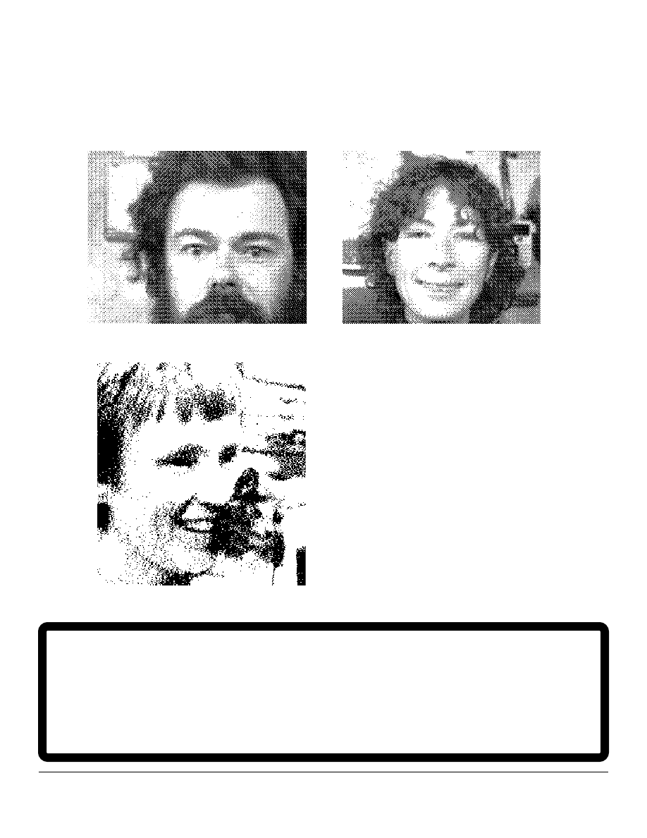
39
Home Power 2 January 1988
Home Power People
To All AE Equipment Manufacturers & Future Home Power
Advertisers:
Your Ad could have been here on 10,000 copies of Home Power. This nationally
distributed information is read by folks with only one interest in mind: making
their own power. So, contact Glenda at 916-475-3179. Then we can stop using
the inside back cover for blatant self-aggrandizement just because it's left over.
Rich
Karen
Glenda
F
or all you Techno freaks
out there, the digitalized
images of the Home Power
crew on this page were
produced using a Macintosh
computer, a CBC video
camera, and the wonderful
MacMagic imaging software.
The whole mess was
powered using Kyocera
PVs, Trojan batteries, and a
Heliotrope inverter.
Letters
Home Power 2 January 1988
40
Home Power 2 January 1988
FLOWLIGHT SOLAR PUMPS
DC SOLAR WELL & BOOSTER PUMPS
FLOWLIGHT LOW-POWER WELL PUMPS PUMP
SLOWLY THROUGHOUT THE SOLAR DAY FOR
HIGHEST EFFICIENCY AND ECONOMY
"SLOWPUMP"
draws from shallow water sources and pushes
as high as 450 vertical ft. It also fits into deep well casings
where the water level remains stable. Many models available,
35 to 300 Watts. SLOWPUMPS have a 5 year history of proven
reliability, worldwide.
"MICRO-SUBMERSIBLE"
raises water from deep wells.
Max. lift measured from water surface: 100 ft. Runs directly from
a single 35 Watt solar module! or from any battery system.
"FLOWLIGHT BOOSTER PUMP"
provides "TOWN
PRESSURE" for home use with minimal energy drain. Far
cheaper and more effective than an elevated tank. 12 or 24 volt
DC power requirement reduces or eliminates inverter needs.
* FLOWLIGHT SOLAR PUMPS *
Division of Windlight Workshop
PO BOX 548, SANTA CRUZ, NM 87567
(505) 753-9699
WINDLIGHT WORKSHOP is a leading supplier of independent
electrical systems by mail order. Please call or write for details
on pumping or home power.
The Complete Battery Book
by Richard Perez
Essential Information for Battery Users
and AE People.
Covers 15 types of batteries- inc. Lead-Acid & Ni-Cads.
Many details on applying batteries in AE systems.
186 pgs. softcover. $19.45, postpaid in USA, from:
Electron Connection Limited
Post Office Box 442, Medford, OR 97501
tele: 916-475-3179
Document Outline
- Table of Contents
- From Us to You-
- Solar- Pvs and our Future
- Systems– A Working PV/Engine System
- Solar– How to Mount and Wire PV Modules
- Communications– Back Country Com
- Hydro- Seeking Our Own Level
- Engines– Build Your Own 12VDC Generator
- Heat– The Fireside
- Things that Work-- The Trace 1512 Inverter
- Batteries-- Build an Accurate Battery Voltmeter
- Basic Electricity-- Low Voltage Wiring Techniques
- The Wizard
- Letters to Home Power
- Micro Ads
Wyszukiwarka
Podobne podstrony:
Home Power Magazine 004 Renewable Solar Wind Energy
Home Power Magazine 005 Renewable Solar Wind Energy
Home Power Magazine 012 Aug Sep 1989 Renewable Solar Wind Energy
Home Power Magazine 007 Oct Nov 1988 Renewable Solar Wind Energy
Home Power Magazine 003 Feb 1988 Renewable Solar Wind Energy
Home Power Magazine 001 Nov 1987 Renewable Solar Wind Energy
Home Power Magazine 008 Dec 88 Jan 89 Renewable Solar Wind Energy
Home Power Magazine 006 Aug Sep 1988 Renewable Solar Wind Energy
Home Power Magazine Betting the Farm Wind Electricity Pays Off
[ebook renewable energy] Home Power Magazine 'Correct Solar Panel Tilt Angle to Sun'
[ebook renewable energy] Home Power Magazine 'Correct Solar Panel Tilt Angle to Sun'
Home Power Magazine Issue 072 Extract p34 Solar Hot Air Collectors
Home Power Magazine 024 Extract p26 p30 All Solar Panels Ever Tested
Home Power Magazine Issue 109 Extract pg22 Making Sense of Solar Electricity Costs
Home Power Magazine Extract Installation Basics For Solar Domestic Water Heating Systems Part 2
Home Power Magazine Issue 063 Extract p42 Solar charge controller for Medium Power Applications
więcej podobnych podstron