
PDF generated using the open source mwlib toolkit. See http://code.pediapress.com/ for more information.
PDF generated at: Sat, 20 Nov 2010 23:46:36 UTC
Embedded Systems
Building and Programming Embedded
Devices

Contents
Articles
Wikibooks:Collections Preface
1
Embedded Systems/Embedded Systems Introduction
2
Embedded Systems/Terminology
6
Microprocessor Basics
9
Embedded Systems/Microprocessor Introduction
9
Embedded Systems/Embedded System Basics
10
Embedded Systems/Microprocessor Architectures
12
Embedded Systems/Programmable Controllers
15
Embedded Systems/Floating Point Unit
17
Embedded Systems/Parity
19
Embedded Systems/Memory
20
Embedded Systems/Memory Units
23
Programming Embedded Systems
24
Embedded Systems/C Programming
24
Embedded Systems/Assembly Language
30
Embedded Systems/Mixed C and Assembly Programming
32
Embedded Systems/IO Programming
37
Embedded Systems/Serial and Parallel IO
38
Embedded Systems/Super Loop Architecture
39
Embedded Systems/Protected Mode and Real Mode
41
Embedded Systems/Bootloaders and Bootsectors
42
Embedded Systems/Terminate and Stay Resident
43
Real Time Operating Systems
44
Embedded Systems/Real-Time Operating Systems
44
Embedded Systems/Threading and Synchronization
46
Embedded Systems/Interrupts
49
Embedded Systems/RTOS Implementation
50
Embedded Systems/Locks and Critical Sections
52
Embedded Systems/Common RTOS
55
Embedded Systems/Common RTOS/Palm OS
57
Embedded Systems/Common RTOS/Windows CE
58

Embedded Systems/Common RTOS/DOS
58
Embedded Systems/Linux
59
Interfacing
62
Embedded Systems/Interfacing Basics
62
Embedded Systems/External ICs
63
Embedded Systems/Low-Voltage Circuits
63
Embedded Systems/High-Voltage Circuits
65
Particular Microprocessor Families
67
Embedded Systems/Particular Microprocessors
67
Embedded Systems/Intel Microprocessors
70
Embedded Systems/PIC Microcontroller
71
Embedded Systems/8051 Microcontroller
76
Embedded Systems/Freescale Microcontrollers
80
Embedded Systems/Atmel AVR
81
Embedded Systems/ARM Microprocessors
98
Embedded Systems/AT91SAM7S64
99
Embedded Systems/Cypress PSoC Microcontroller
100
Appendices
106
Embedded Systems/Common Protocols
106
Embedded Systems/Where To Buy
107
Resources and Licensing
108
Embedded Systems/Resources
108
Embedded Systems/Licensing
110
References
Article Sources and Contributors
111
Image Sources, Licenses and Contributors
113
Article Licenses
License
114

Wikibooks:Collections Preface
1
Wikibooks:Collections Preface
This book was created by volunteers at Wikibooks (http:/
What is Wikibooks?
Started in 2003 as an offshoot of the popular Wikipedia project, Wikibooks is
a free, collaborative wiki website dedicated to creating high-quality textbooks
and other educational books for students around the world. In addition to
English, Wikibooks is available in over 130 languages, a complete listing of
which can be found at http:/
which means anybody can edit the content there at any time. If you find an
error or omission in this book, you can log on to Wikibooks to make
corrections and additions as necessary. All of your changes go live on the
website immediately, so your effort can be enjoyed and utilized by other
readers and editors without delay.
Books at Wikibooks are written by volunteers, and can be accessed and printed for free from the website. Wikibooks
is operated entirely by donations, and a certain portion of proceeds from sales is returned to the Wikimedia
Foundation to help keep Wikibooks running smoothly. Because of the low overhead, we are able to produce and sell
books for much cheaper then proprietary textbook publishers can. This book can be edited by anybody at any
time, including you. We don't make you wait two years to get a new edition, and we don't stop selling old versions
when a new one comes out.
What is this book?
This book was generated by the volunteers at Wikibooks, a team of people from around the world with varying
backgrounds. The people who wrote this book may not be experts in the field. Some may not even have a passing
familiarity with it. The result of this is that some information in this book may be incorrect, out of place, or
misleading. For this reason, you should never rely on a community-edited Wikibook when dealing in matters of
medical, legal, financial, or other importance. Please see our disclaimer for more details on this.
Despite the warning of the last paragraph, however, books at Wikibooks are continuously edited and improved. If
errors are found they can be corrected immediately. If you find a problem in one of our books, we ask that you be
bold in fixing it. You don't need anybody's permission to help or to make our books better.
Wikibooks runs off the assumption that many eyes can find many errors, and many able hands can fix them. Over
time, with enough community involvement, the books at Wikibooks will become very high-quality indeed. You are
invited to participate at Wikibooks to help make our books better. As you find problems in your book don't just
complain about them: Log on and fix them! This is a kind of proactive and interactive reading experience that you
probably aren't familiar with yet, so log on to http:/
org and take a look around at all the
possibilities. We promise that we won't bite!
Who are the authors?
The volunteers at Wikibooks come from around the world and have a wide range of educational and professional
backgrounds. They come to Wikibooks for different reasons, and perform different tasks. Some Wikibookians are
prolific authors, some are perceptive editors, some fancy illustrators, others diligent organizers. Some Wikibookians
find and remove spam, vandalism, and other nonsense as it appears. Most wikibookians perform a combination of
these jobs.

Wikibooks:Collections Preface
2
It's difficult to say who are the authors for any particular book, because so many hands have touched it and so many
changes have been made over time. It's not unheard of for a book to have been edited thousands of times by
hundreds of authors and editors. You could be one of them too, if you're interested in helping out. At the time this
book was prepared for print, there have been over ' edits made by over 0' registered users. These numbers are
growing every day.
Wikibooks in Class
Books at Wikibooks are free, and with the proper editing and preparation they can be used as cost-effective
textbooks in the classroom or for independent learners. In addition to using a Wikibook as a traditional read-only
learning aide, it can also become an interactive class project. Several classes have come to Wikibooks to write new
books and improve old books as part of their normal course work. In some cases, the books written by students one
year are used to teach students in the same class next year. Books written can also be used in classes around the
world by students who might not be able to afford traditional textbooks.
Happy Reading!
We at Wikibooks have put a lot of effort into these books, and we hope that you enjoy reading and learning from
them. We want you to keep in mind that what you are holding is not a finished product but instead a work in
progress. These books are never "finished" in the traditional sense, but they are ever-changing and evolving to meet
the needs of readers and learners everywhere. Despite this constant change, we feel our books can be reliable and
high-quality learning tools at a great price, and we hope you agree. Never hesitate to stop in at Wikibooks and make
some edits of your own. We hope to see you there one day. Happy reading!
Embedded Systems/Embedded Systems
Introduction
Embedded Technology is now in its prime and the wealth of knowledge available is mindblowing. However, most
embedded systems engineers have a common complaint. There are no comprehensive resources available over the
internet which deal with the various design and implementation issues of this technology. Intellectual property
regulations of many corporations are partly to blame for this and also the tendency to keep technical know-how
within a restricted group of researchers.
Before embarking on the rest of this book, it is important first to cover exactly what embedded systems are, and how
they are used. This wikibook will attempt to cover a large number of topics, some of which apply only to embedded
systems, but some of which will apply to nearly all computers (embedded or otherwise). As such, there is a chance
that some of the material from this book will overlap with material from other wikibooks that are focused on topics
such as low-level computing, assembly language, computer architecture, etc. But we will first start with the basics,
and attempt to answer some questions before the book actually begins.
What is an Embedded Computer?
The first question that needs to be asked, is "What exactly is an embedded computer?" To be fair, however, it is
much easier to answer the question of what an embedded computer is not, than to try and describe all the many
things that an embedded computer can be. An embedded computer is frequently a computer that is implemented for a
particular purpose. In contrast, an average PC computer usually serves a number of purposes: checking email,
surfing the internet, listening to music, word processing, etc... However, embedded systems usually only have a
single task, or a very small number of related tasks that they are programmed to perform.

Embedded Systems/Embedded Systems Introduction
3
Every home has several examples of embedded computers. Any appliance that has a digital clock, for instance, has a
small embedded microcontroller that performs no other task than to display the clock. Modern cars have embedded
computers onboard that control such things as ignition timing and anti-lock brakes using input from a number of
different sensors.
Embedded computers rarely have a generic interface, however. Even if embedded systems have a keypad and an
LCD display, they are rarely capable of using many different types of input or output. An example of an embedded
system with I/O capability is a security alarm with an LCD status display, and a keypad for entering a password.
In general, an Embedded System:
• Is a system built to perform its duty, completely or partially independent of human intervention.
• Is specially designed to perform a few tasks in the most efficient way.
• Interacts with physical elements in our environment, viz. controlling and driving a motor, sensing temperature,
etc.
An embedded system can be defined as a control system or computer system designed to perform a specific task.
Common examples of embedded systems include MP3 players, navigation systems on aircraft and intruder alarm
systems. An embedded system can also be defined as a single purpose computer.
Most embedded systems are time critical applications meaning that the embedded system is working in an
environment where timing is very important: the results of an operation are only relevant if they take place in a
specific time frame. An autopilot in an aircraft is a time critical embedded system. If the autopilot detects that the
plane for some reason is going into a stall then it should take steps to correct this within milliseconds or there would
be catastrophic results.
What are Embedded Systems Used For?
The uses of embedded systems are virtually limitless, because every day new products are introduced to the market
that utilize embedded computers in novel ways. In recent years, hardware such as microprocessors, microcontrollers,
and FPGA chips have become much cheaper. So when implementing a new form of control, it's wiser to just buy the
generic chip and write your own custom software for it. Producing a custom-made chip to handle a particular task or
set of tasks costs far more time and money. Many embedded computers even come with extensive libraries, so that
"writing your own software" becomes a very trivial task indeed.
From an implementation viewpoint, there is a major difference between a computer and an embedded system.
Embedded systems are often required to provide Real-Time response. A Real-Time system is defined as a system
whose correctness depends on the timeliness of its response. Examples of such systems are flight control systems of
an aircraft, sensor systems in nuclear reactors and power plants. For these systems, delay in response is a fatal error.
A more relaxed version of Real-Time Systems, is the one where timely response with small delays is acceptable.
Example of such a system would be the Scheduling Display System on the railway platforms. In technical
terminology, Real-Time Systems can be classified as:
• Hard Real-Time Systems - systems with severe constraints on the timeliness of the response.
• Soft Real-Time Systems - systems which tolerate small variations in response times.
• Hybrid Real-Time Systems - systems which exhibit both hard and soft constraints on its performance.

Embedded Systems/Embedded Systems Introduction
4
What are Some Downfalls of Embedded Computers?
Embedded computers may be economical, but they are often prone to some very specific problems. A PC computer
may ship with a glitch in the software, and once discovered, a software patch can often be shipped out to fix the
problem. An embedded system, however, is frequently programmed once, and the software cannot be patched. Even
if it is possible to patch faulty software on an embedded system, the process is frequently far too complicated for the
user.
Another problem with embedded computers is that they are often installed in systems for which unreliability is not
an option. For instance, the computer controlling the brakes in your car cannot be allowed to fail under any
condition. The targeting computer in a missile is not allowed to fail and accidentally target friendly units. As such,
many of the programming techniques used when throwing together production software cannot be used in embedded
systems. Reliability must be guaranteed before the chip leaves the factory. This means that every embedded system
needs to be tested and analyzed extensively.
An embedded system will have very few resources when compared to full blown computing systems like a desktop
computer, the memory capacity and processing power in an embedded system is limited. It is more challenging to
develop an embedded system when compared to developing an application for a desktop system as we are
developing a program for a very constricted environment. Some embedded systems run a scaled down version of
operating system called an RTOS (real time operating system).
Why Study Embedded Systems?
Embedded systems are playing important roles in our lives every day, even though they might not necessarily be
visible. Some of the embedded systems we use every day control the menu system on television, the timer in a
microwave oven, a cellphone, an MP3 player or any other device with some amount of intelligence built-in. In fact,
recent poll data shows that embedded computer systems currently outnumber humans in the USA. Embedded
systems is a rapidly growing industry where growth opportunities are numerous.
Who is This Book For?
This book is designed to accompany a course of study in computer engineering. However, this book will also be
useful to any reader who is interested in computers, because this book can form the starting point for a "bottom up"
learning initiative on computers. It is fundamentally easier to study small, limited, simple computers than it is to start
studying the big PC behemoths that we use on a daily basis. Many topics covered in this book will be software topics
as well, so this book will be the most helpful to people with at least some background in programming (especially C
and Assembly languages). Having a prior knowledge of semiconductors and electric circuits will be beneficial, but
will not be required.
What Will This Book Cover?
This book will focus primarily on embedded systems, but the reader needs to understand 2 simple facts:
1. This book cannot proceed far without a general discussion of microprocessor architecture
2. Many of the concepts discussed in this book apply equally well, if not better, to Desktop computers than to
embedded computers.
In the general interests of completeness, this book will cover a number of topics that have general relevance to all
computers in general. Many of the lessons in this book will even be better applied by a desktop computer
programmer than by an embedded systems engineer. It might be more fair to say that this book is more about "Low
Level Computing" than "Embedded Systems".

Embedded Systems/Embedded Systems Introduction
5
This book will, of course, cover many embedded systems topics that are irrelevant when programming desktop
computers, such as cross-compilers, Real-Time Operating Systems, EEPROM storage, code compression,
bit-banging serial ports, umbilical development, etc.
Where to Go From Here
After reading this book, there are a number of potential fields of study to continue learning.
• For people interested in operating systems, and hardware-software interfacing, read the Operating System Design
wikibook.
• For people interested in C programming or Assembly Programming, see the Programming:C and X86 Assembly
wikibooks, respectively.
• For people interested in digital signal processing, there will eventually be a book on that subject.
• For people interested in a further study of more advanced computer systems, there will eventually be books on
computer hardware and microprocessors here. ( Microprocessor Design )
• For people interested in an even lower-level understanding of electronics, see Digital Circuits.
• Wikiversity: School of Very Small Information Systems is a course that includes using Java running on a FPGA.
• For people interested in designing motion control systems, that is, computer-controlled machines such as robots,
machine tools, cars, buses, airplanes, ships, satellites, telescopes, etc., see Embedded Control Systems Design.
Which Programming Languages Will This Book Use?
We try to make this wikibook language neutral. It is not fair to focus on one language, when all embedded
computers can't be programmed in that language.
However, it is nice to have functional example code in some real language. Also, it is useful to point out some
features of popular programming languages that are especially important for embedded systems.
• ANSI C programming language: Many microprocessors and microcontrollers can be programmed in C, and a
number of C cross-compilers exist for that purpose. C is perhaps the most frequently used language for new
embedded system development. The "const" and the "volatile" keywords, rarely used in desktop app
programming, become very important in Embedded Systems/C Programming.
• Originally developed by the department of defense for real-time operating systems and embedded systems, Ada
was designed with multiprocessor support and strong compile-time checks to ensure the quality and integrity
of developed systems -- Many microcontrollers can be programmed with Ada as the GNAT
Ada compiler it is
part of the often ported GNU Compiler Collection
, though documentation is often not as available as other
more popular languages such as C.
• Assembly language: There are many different microcontroller families, each with their own assembly language
with its own unique quirks. This book will cover some basics of assembly language common to most
microcontrollers. Unlike desktop app programming, embedded system programs generally must set up an
"interrupt vector table".
• This book will discuss (at least briefly) some techniques for multi-language programming (specifically C and
assembly).
• There are some instances where microcontrollers are better programmed in a different language (BASIC and
Forth come to mind)
• Some controllers are even programmed in their own proprietary languages (PIC Basic, and Dynamic C
instance).
• Some extremely well-known languages, such as C++ and Java, are rarely used in embedded systems, because
C++ and Java compilers are simply unavailable for popular microcontrollers. However, this book may

Embedded Systems/Embedded Systems Introduction
6
occasionally describe how to implement C++ and Java features in an environment that doesn't natively support
them.
• Python compilers are available for some popular microcontrollers. Pyastra[5] compiles for all Microchip PIC12,
KiB program memory and 4 KiB RAM". PyMite also targets (some) ARM microcontrollers. Notice that these
embedded Python compilers typically can only compile a subset of the Python language for these devices.
Further reading:
• Robotics: Design Basics: Design software#Programming Languages
• Embedded Systems/PIC Programming#Compilers.2C_Assemblers
References
[1] http:/
Ada_%28programming_language%29
[2] http:/
[3] http:/
[4] http:/
[5] http:/
[6] http:/
Embedded Systems/Terminology
This page will try to discuss some of the different, important terminology, and it may even contain a listing of some
of the acronyms used in this book.
Types of Chips
There are a number of different types of chips that we will discuss here.
Microprocessors
These chips contain a processing core, and occasionally a few integrated peripherals. In a different sense,
Microprocessors are simply CPUs found in desktops.
Microcontrollers
These chips are all-in-one computer chips. They contain a processing core, memory, and integrated
peripherals. In a broader sense, a microcontroller is a CPU that is used in an embedded system.
Digital Signal Processor (DSP)
DSPs are the "best of the best" when it comes to microcontrollers. DSPs frequently run very quickly, and have
immense processing power (for an embedded chip). Digital Signal Processors, and the field of Digital Signal
Processing is so large and involved, that it warrants its own book -- Digital Signal Processing.

Embedded Systems/Terminology
7
Grades of Microcontrollers
Microcontrollers can be divided up into different categories, depending on several parameters such as bus-width (8
bit, 16 bit, etc...), amount of memory, speed, and the number of I/O pins:
Low-end
Low-end chips are frequently used in simple situations, where speed and power are not a factor. Low-end
chips are the cheapest of the bunch, and can usually cost less than a dollar, depending on the quantity in which
they are purchased. Low-end chips rarely have many I/O pins (4 or 8, total), and rarely have any special
capabilities. Almost all low-end chips are 8 bits or smaller.
Mid-level chips
mid-level chips are the "basic" microcontroller units. They don't suffer from the drawbacks of the low-end
chips, but at the same time they are more expensive and larger. Mid-level chips are 8 bits or 16 bits wide, and
frequently have a number of available I/O pins to play with. Mid-level chips may come with ADC, voltage
regulators, OpAmps, etc... Mid-level chips can cost anywhere between $1 and $10 for reasonable chips.
High-end chips
High end chips are used in situations where power and speed are a must, but a conventional microprocessor
board (think a computer motherboard) is too large or expensive. High-end chips will have a number of fancy
features, more available memory, and a larger addressable memory range. High end chips can come in 8 bit,
16 bit, 32 bit or even 64 bit, and can cost anywhere between $10 to $100 each.
Acronyms
This will be a functional list of most of the acronyms used in this book
ADC
ADC stands for Analog to Digital Converter. ADCs are also written as "A/D" or "A2D" in other literature.
DAC
The exact opposite of an ADC, a DAC stands for Digital to Analog Converter. May also be called "D/A" or
"D2A"
RAM
Random-Access Memory. RAM is the memory that a microcontroller uses to store information when the
power is on. When the power goes off, RAM is erased.
ROM
Read-Only Memory, ROM is memory that can be read, but it cant be written or erased. ROM is cheaper than
RAM, and it doesnt lose its information when the power is turned off.
OTP
OTP means One-Time Programmable. OTP chips can be programmed once, and only once, usually by a
physical process or burning extra wires inside the chip. If an OTP chip is programmed incorrectly, it can't be
fixed, so be careful with them.

Embedded Systems/Terminology
8
downloading
In this book, the terms "burning", "flashing", "installing", or "downloading" all mean the same thing -- the automated
process of putting the executable image into the non-volatile memory of the embedded system.
After a person tweaks the source code and compiles a new executable image on the PC, that person connects a
downloader between the PC and the embedded system, and clicks the "go" button. Then the PC streams the image
into the downloader, and the downloader burns the image into the embedded system.
A downloader is variously called a "downloader", "burner", "flasher", "flash downloader", "programming interface",
or -- confusingly -- a "programmer".
• Embedded_Systems/PIC_Microcontroller#downloaders
• Embedded_Systems/Atmel_AVR#Programming_Interfaces
programming
Sometimes "programming" means the overall process of a person writing software on a PC, going through many
edit-compile-download-burn-test cycles. Other times "programming" means the specific step of the "programmer"
device burning the compiled code into the chip. Please help us make this book less confusing.
In this book, we use the term "programming" to describe what a human being does to create and test software source
code.
Be aware that other texts may use the term "programming" -- such as when talking about "high-voltage
programming", "gang programming", etc. -- to describe what we would call "installing". They may call the piece of
hardware that does it a "programmer".
Texts that talk about "C++ programming", "assembly programming", "pair programming" etc. -- use "programming"
the same way we do. "C++ programmer", "Python programmer", "pair programmer", etc. refer to human beings that
do the programming.
for further reading
• We mentioned op amps. A long time ago, "analog computers" were once built entirely out of such operational
amplifiers, resistors and capacitors. Today most embedded systems have few, if any op-amps -- they are still
useful for some sensor signal amplifiers, anti-aliasing filters before the ADC, anti-aliasing filters after the DAC,
and a few op-amps embedded in power supply circuits.

9
Microprocessor Basics
Embedded Systems/Microprocessor Introduction
Effectively programming an embedded system, and implementing it reliably requires the engineer to know many of
the details of the system architecture. Section 1 of the Embedded Systems book will cover some of the basics of
microprocessor architecture. This information might not apply to all embedded computers, and much of it may apply
to computers in general. This book can only cover some basic concepts, because the actual embedded computers
available on the market are changing every day, and it is the engineer's responsibility to find out what capabilities
and limitations their particular systems have.
As people continue to pack more and more transistors onto a single chip, more and more of the stuff that was once
"peripheral logic" has been integrated on the same chip as the CPU. A microcontroller includes most or all the
electronics needed in an embedded system in a single integrated circuit ("chip").
[1]
• CPU
• I/O ports
• RAM - contains temporary data
• "ROM" - contains program and constant data -- the firmware. Starting in 1993, many microcontrollers use Flash
memory instead of true ROM to hold the firmware, but many engineers still refer to the Flash memory that holds
the firmware as "ROM" from force of habit.
• timers -- we discuss these later at Embedded Systems/Programmable Controllers#Timers.
• serial interface -- often a USART -- we discuss these later at Embedded Systems/Serial and Parallel IO
• EEPROM - contains "permanent" data
• analog-to-digital converter
This list is roughly in order of integration. The earliest microcontrollers contained only the CPU and I/O ports;
modern microprocessors typically contain the CPU, some I/O ports, and a lot of cache RAM; the cost of a
microcontroller dropped dramatically once the CPU, I/O, RAM, and ROM could all be squeezed onto the same chip,
because such a microcontroller no longer needs "address pins"; etc. The most highly integrated microcontrollers
include all these parts on one chip.
Should we say something about "Harvard architecture" here?
Further reading
Learn Electronics/Microprocessors
[1] "Microcontrollers made easy" (http:/
pdf) ST AN887

Embedded Systems/Embedded System Basics
10
Embedded Systems/Embedded System Basics
Embedded systems programming is not like normal PC programming. In many ways, programming for an embedded
system is like programming a PC 15 years ago. The hardware for the system is usually chosen to make the device as
cheap as possible. Spending an extra dollar a unit in order to make things easier to program can cost millions. Hiring
a programmer for an extra month is cheap in comparison. This means the programmer must make do with slow
processors and low memory, while at the same time battling a need for efficiency not seen in most PC applications.
Below is a list of issues specific to the embedded field.
Tools
Embedded development makes up a small fraction of total programming. There's also a large number of embedded
architectures, unlike the PC world where 1 instruction set rules, and the Unix world where there's only 3 or 4 major
ones. This means that the tools are more expensive. It also means that they're lower featured, and less developed. On
a major embedded project, at some point you will almost always find a compiler bug of some sort.
Debugging tools are another issue. Since you can't always run general programs on your embedded processor, you
can't always run a debugger on it. This makes fixing your program difficult. Special hardware such as JTAG ports
can overcome this issue in part. However, if you stop on a breakpoint when your system is controlling real world
hardware (such as a motor), permanent equipment damage can occur. As a result, people doing embedded
programming quickly become masters at using serial IO channels and error message style debugging.
Resources
To save costs, embedded systems frequently have the cheapest processors that can do the job. This means your
programs need to be written as efficiently as possible. When dealing with large data sets, issues like memory cache
misses that never matter in PC programming can hurt you. Luckily, this won't happen too often- use reasonably
efficient algorithms to start, and optimize only when necessary. Of course, normal profilers won't work well, due to
the same reason debuggers don't work well. So more intuition and an understanding of your software and hardware
architecture is necessary to optimize effectively.
Memory is also an issue. For the same cost savings reasons, embedded systems usually have the least memory they
can get away with. That means their algorithms must be memory efficient (unlike in PC programs, you will
frequently sacrifice processor time for memory, rather than the reverse). It also means you can't afford to leak
. Embedded applications generally use deterministic memory techniques and avoid the default "new" and
"malloc" functions, so that leaks can be found and eliminated more easily.
Other resources programmers expect may not even exist. For example, most embedded processors do not have
hardware FPUs
(Floating-Point Processing Unit). These resources either need to be emulated in software, or
avoided altogether.

Embedded Systems/Embedded System Basics
11
Real Time Issues
Embedded systems frequently control hardware, and must be able to respond to them in real time. Failure to do so
could cause inaccuracy in measurements, or even damage hardware such as motors. This is made even more difficult
by the lack of resources available. Almost all embedded systems need to be able to prioritize some tasks over others,
and to be able to put off/skip low priority tasks such as UI in favor of high priority tasks like hardware control.
Fixed-Point Arithmetic
Some embedded microprocessors may have an external unit for performing floating point arithmetic(FPU), but most
low-end embedded systems have no FPU. Most C compilers will provide software floating point support, but this is
significantly slower than a hardware FPU. As a result, many embedded projects enforce a no floating point rule on
their programmers. This is in strong contrast to PCs, where the FPU has been integrated into all the major
microprocessors, and programmers take fast floating point number calculations for granted. Many DSPs also do not
have an FPU and require fixed-point arithemtic to obtain acceptable performance.
A common technique used to avoid the need for floating point numbers is to change the magnitude of data stored in
your variables so you can utilize fixed point mathematics. For example, if you are adding inches and only need to be
accurate to the hundreth of an inch, you could store the data as hundreths rather than inches. This allows you to use
normal fixed point arithmetic. This technique works so long as you know the magnitude of data you are adding
ahead of time, and know the accuracy to which you need to store your data.
We will go into more detail on fixed-point and floating-point numbers in a later chapter.
further reading
• Floating Point/Fixed-Point Numbers
References
[1] http:/
[2] http:/

Embedded Systems/Microprocessor Architectures
12
Embedded Systems/Microprocessor
Architectures
The chapters in this section will discuss some of the basics in microprocessor architecture. They will discuss how
many features of a microprocessor are implemented, and will attempt to point out some of the pitfalls (speed
decreases and bottlenecks, specifically) that each feature represents to the system.
Memory Bus
In a computer, a processor is connected to the RAM by a data bus. The data bus is a series of wires running in
parallel to each other that can send data to the memory, and read data back from the memory. In addition, the
processor must send the address of the memory to be accessed to the RAM module, so that the correct information
can be manipulated.
Multiplexed Address/Data Bus
In old microprocessors, and in some low-end versions today, the memory bus is a single bus that will carry both the
address of the data to be accessed, and then will carry the value of the data. Putting both signals on the same bus, at
different times is a technique known as "time division multiplexing", or just multiplexing for short. The effect of a
multiplexed memory bus is that reading or writing to memory actually takes twice as long: half the time to send the
address to the RAM module, and half the time to access the data at that address. This means that on a multiplexed
bus, moving data to and from the memory is a very expensive (in terms of time) process, and therefore memory
read/write operations should be minimized. It also makes it important to ensure algorithms which work on large
datasets are cache efficient.
Demultiplexed Bus
The opposite of a multiplexed bus is a demultiplexed bus. A demultiplexed bus has the address on one set of wires,
and the data on another set. This scheme is twice as fast as a multiplexed system, and therefore memory read/write
operations can occur much faster.
Bus Speed
In modern high speed microprocessors, the internal CPU clock may move much faster than the clock that
synchronizes the rest of the microprocessor system. This means that operations that need to access resources outside
the processor (the RAM for instance) are restricted to the speed of the bus, and cannot go as fast as possible. In these
situations, microprocessors have 2 options: They can wait for the memory access to complete (slow), or they can
perform other tasks while they are waiting for the memory access to complete (faster). Old microprocessors and
low-end microprocessors will always take the first option (so again, limit the number of memory access operations),
while newer, and high-end microprocessors will often take the second option.
I/O Bus
Any computer, be it a large PC or a small embedded computer, is useless if it has no means to interact with the
outside world. I/O communications for an embedded computer frequently happen over a bus called the I/O Bus.
Like the memory bus, the I/O bus frequently multiplexes the input and output signals over the same bus. Also, the
I/O bus is moving at a slower speed than the processor is, so large numbers of I/O operations can cause a severe
performance bottleneck.

Embedded Systems/Microprocessor Architectures
13
It is not uncommon for different IO methods to have separate buses. Unfortunately, it is also not uncommon for the
electrical engineers designing the hardware to cheat and use a bus for more than 1 purpose. Doing so can save the
need for extra transistors in the layout, and save cost. For example, a project may use the USB bus to talk to some
LEDs that are physically close by. These different devices may have very different speeds of communication. When
programming IO bus control, make sure to take this into account.
In some systems, memory mapped IO is used. In this scheme, the hardware reads its IO from predefined memory
addresses instead of over a special bus. This means you'll have simpler software, but it also means main memory will
get more access requests.
Programming the IO Bus
When programming IO bus controls, there are 5 major variations on how to handle it- the main thread poll, the
multithread poll, the interrupt method, the interrupt+thread method, and using a DMA controller.
Main thread poll
In this method, whenever you have output ready to be sent, you check if the bus is free and send it. Depending on
how the bus works, sending it can take a large amount of time, during which you may not be able to do anything
else. Input works similarly- every so often you check the bus to see if input exists.
Pros:
• Simple to understand
Cons:
• Very inefficient, especially if you need to push the data manually over the bus (instead of via DMA)
• If you need to push data manually, you are not doing anything else, which may lead to problem with real time
hardware
• Depending on polling frequency and input frequency, you could lose data by not handling it fast enough
In general, this system should only be used if IO only occurs at infrequent intervals, or if you can put it off when
there are more important things to do. If your system supports multithreading or interrupts, you should use other
techniques instead.
Multithread polling
In this method, we spawn off a special thread to poll. If there is no IO when it polls, it puts itself back to sleep for a
predefined amount of time. If there is IO, it deals with it on the IO thread, allowing the main thread to do whatever is
needed.
Pros:
• Does not put off the main thread
• Allows you to define the importance of IO by changing the priority of the thread
Cons:
• Still somewhat inefficient
• If IO occurs frequently, your polling interval may be too small for you to sleep sufficiently, starving other threads
• If your thread is too low in priority or there are too many threads for the OS to wake the thread in a timely
fashion, data can be lost.
• Requires an OS capable of threading
This technique is good if your system supports threading, but does not support interrupts or has run out of interrupts.
It does not work well when frequent IO is expected- the OS may not properly sleep the thread if the interval is too
small, and you will be adding the overhead of 2 context switches per poll.

Embedded Systems/Microprocessor Architectures
14
Interrupt architecture
(The interrupt architecture uses interrupts, which we discuss in more detail in chapter Embedded
In this method, the bus fires off an interrupt to the processor whenever IO is ready. The processor then jumps to a
special function, dropping whatever else it was doing. The special function (called an interrupt handler, or interrupt
service routine) takes care of all IO, then goes back to whatever it was doing.
Pros:
• Very efficient
• Very simple, requires only 1 function
Cons:
• If dealing with IO takes a long time, you can starve other things. This is especially dangerous if your handler
masks interrupts, which can cause you to miss hardware interrupts from real time hardware
• If your handler takes so long more input is ready before you handle existing input, data can be lost.
This technique is great so long as dealing with the IO is a short process, such as when you just need to set up DMA.
If its a long process, use multithreaded polling or interrupts with threads.
Interrupts and threads
We discuss this technique in more detail in Embedded Systems/Interrupts
In this technique, you use an interrupt to detect when IO is ready. Instead of dealing with the IO directly, the
interrupt signals a thread that IO is ready and lets that thread deal with it. Signalling the thread is usually done via
semaphore- the semaphore is initialized to the taken state. The IO thread tries to take the semaphore, which fails and
the OS puts it to sleep. When IO is ready, the interrupt is fired and releases the semaphore. The thread then wakes
up, and handles the IO before trying to take the semaphore and being put back to sleep.
The routine the interrupt vector points at is the "first level interrupt handler". The thread that the OS later wakes up
to handle the rest of the work is the "second level interrupt handler".
Pros:
• minimum latency -- instead of all other interrupts being disabled until that interrupt is completely handled,
interrupts are turned back on (at the end of the first level interrupt handler) as soon as possible.
• Does not put off the main thread
• Allows you to define the importance of IO by changing the priority of the thread
• Very efficient- only makes context changes when needed and does not poll.
• Very clean solution architecturally, allows you to be very flexible in how you handle IO.
Cons:
• Requires an OS capable of threading
• Most complex solution
This solution is the most flexible, and one of the most efficient. It also minimizes the risk of starving more important
tasks. Its probably the most common method used today.

Embedded Systems/Microprocessor Architectures
15
DMA (Direct Memory Access) Controller
In some specialised situations, such as where a set of data must be transfered to a communications IO device, a
DMA controller may be present that can automatically detect when the IO device is ready for more data, and transfer
that data. This technique may be used in conjuction with many of the other techniques, for instance an interrupt may
be used when the data transfer is complete.
Pros:
• This provides the best performance, since the I/O can happen in parallel with other code execution
Cons:
• Only applicable to a limited range of problems
• Not all systems have DMA controllers. This is especially true of the more basic 8-bit microcontrollers.
• Parallel nature may complicate a system
Embedded Systems/Programmable Controllers
The original 8086 processor shipped with a number of peripheral chips that each performed different tasks. Among
these chips were programmable Interrupt controllers, programmable timers, and programmable I/O chips that could
handle many of the tasks of the original computer, to take some of the computational strain off the 8086. In new
versions of Intel chips (486, Pentium, etc) many of the peripheral chips have been integrated into the processor, in an
attempt to speed up the entire computer. However, much of the functionality remains, even in today's high-end
computer systems.
Timers
Timers are incredibly useful for performing a number of different operations. For instance, many multi-threaded
operating systems operate by setting a timer, and then switching to a different thread every time the timer is
triggered. Programmable timer chips can often be programmed to provide a variety of different timing functions, to
take the burden off the microprocessor.
Another common application of a timer is to keep track of the time in human units of hours and minutes, and often
years, months, and days. Often this real-time clock (RTC) has a battery to keep it running even in systems that are
usually plugged into line power. Such a timer can save power in two ways:
• When we want to know what time it is -- for example, when a digital camera time-stamps a picture it just took --
the system can read it from the real-time clock. Other ways of figuring out the time require more energy.
• When a system needs to do something periodically -- for example, measure the outside temperature every 10
seconds, and transmit it wirelessly to an indoor display -- the system can turn off power to everything except the
real-time clock, and then wait for the clock to wake it up.
You can see some of the 8086 compatible timer chips like 8253/54 also they are the same have three independent
timers internally but 8254 can work with higher frequencies and is used to generate interrupt like Memory refresh
interrupt ,Time of day TOD interrupt and the last one is used to generate the speaker frequencies.
Practically all microcontrollers sold today include integrated timer "peripherals" on the same chip. Most embedded
systems either (a) have no external timer chip at all, using only the internal timers, (b) an external real-time clock, or
(c) attempt to be PC compatible with a "southbridge" chip that emulates both the 8253-compatible timers and the
real-time clock.

Embedded Systems/Programmable Controllers
16
Interrupt Controllers
The original 8086 processor had only a single pin used for signaling an interrupt, so a programmable interrupt
controller would handle most of the messy details of calling the interrupt. Also, a programmable interrupt controller
could be used to monitor an input port for instance, and triggering an interrupt routine when input is received.
Direct Memory Access
Since memory read/write operations take longer than other operations for the microprocessor, one should avoid
moving large blocks of memory. Luckily, the original 8086 came with a programmable direct memory access
controller (DMA) for use in automatically copying and moving segments of memory. DMAs could also be used for
implementing memory-mapped I/O, by being programmed to automatically move memory data to and from an
output port.
DMA memory copies can also greatly enhance system performance by allowing the CPU to execute code in parallel
with a DMA controller automatically performing the memory copy.
Peripheral Interface Controllers
Peripheral interface controllers take a number of different forms. Each different type of port has a different controller
that the microprocessor will interface with to send the output on that port. For instance there are controllers for
parallel ports and more modern USB ports. These controllers are used for controlling settings on output such as
timing, and setting different modes on the output/input port.
Further reading

Embedded Systems/Floating Point Unit
17
Embedded Systems/Floating Point Unit
Floating point numbers are ....
Like all information, floating point numbers are represented by bits.
Early computers used a variety of floating-point number formats. Each one required slightly different subroutines to
add, subtract, and do other operations on them.
Because some computer applications use floating point numbers a lot, Intel standardized on one particular format,
and designed floating-point hardware that calculated much more quickly than the software subroutines. The 80186
shipped with a floating-point co-processor dubbed the 80187. The 80187 was a floating point math unit that handled
the floating point arithmetic functions. In newer processors, the floating point unit (FPU) has been integrated directly
into the microprocessor.
Many small embedded systems, however, do not have an FPU (internal or external). Therefore, they manipulate
floating-point numbers, when necessary, the old way. They use software subroutines, often called a "floating point
emulation library".
However, floating-point numbers are not necessary in many embedded systems. Many embedded system
programmers try to eliminate floating point numbers from their programs,
[1]
instead using fixed-point arithmetic.
Such programs use less space (fixed-point subroutine libraries are far smaller than floating-point libaries, especially
when just one or two routines are put into the system). On microprocessors without a floating-point unit, the
fixed-point version of a program usually runs faster than floating-point version. However, these embedded system
programmers must figure out exactly how much accuracy a particular application needs, and make sure their
fixed-point routines maintain at least that much accuracy.
math routines
(Is there a better place in this wikibook for this discussion? It doesn't even mention floating point.)
So on low-end CPUs, you must use routines that synthesize basic math operators (multiply, divide, square root, etc.)
from even simpler steps. Practically all microprocessors have such routines, posted on the internet by their
manufacturer or other users ("Multiplication and Division Made Easy"
by Robert Ashby, "Novel Methods of
Integer Multiplication and Division"
, "efficient bit twiddling methods"
Following the advice known as "Make It Work Make It Right Make It Fast"
and "Make It Work Make It Small
Make It Fast"
, many people pick one or two number resolutions that are adequate for the largest and most precise
kind of data handled in a program, and use that resolution for everything. For desktop machines, often 32-bit integers
and 64 bit "double precision floating point" numbers are more than adequate. For embedded systems, often 24-bit
integers and 24-bit "fixed point" numbers are more than adequate. If the software fits in the microcontroller, and is
plenty fast enough, it is a waste of valuable human time to try to "optimize" it further.
Alas, sometimes the software does not fit in the microcontroller.
• If you run out of RAM, sometimes you only need 2 bytes or 1 byte or 4 bits or 1 bit to store a particular variable.
• If you run out of time, sometimes you can add lower-precision math routines that quickly calculate the results
needed for that inner loop, even though other parts of the code may need higher-precision math routines.
• If you run out of ROM, sometimes you can trade time for ROM space. Rather than a collection of sets of math
routines, each one customized to a slightly different width, you can use a single set of math routines that can
handle the maximum possible width. If you have some variables less than that width (to save RAM), then you
typically sign-extend variables into a full-size register or global buffer, do full-width calculations there, and then
truncate and store the result to the small size.

Embedded Systems/Floating Point Unit
18
FFT
Many people do FFT using fixed-point arithmetic.
... more tips and hints here ...
• "Develop FFT apps on low-power MCUs"
• "Comparing Floating-Point and Fixed-Point Implementations on ADI Blackfin Processors with LabVIEW"
• "Fixed-Point Fast Fourier Transform (FFT)"
• (program listed for a fixed-point FFT)
• EE-18: Choosing and Using FFTs for ADSP-21xx
(a fixed-point DSP)
Further reading
[1] Avoiding floating point arithmetic on the iPhone (http:/
avoiding-floating-point-arithmetic)
[2] http:/
[3] http:/
[4] http:/
[5] http:/
[6] http:/
wiki?MakeItWorkMakeItRightMakeItFast
[7] http:/
wiki?MakeItWorkMakeItSmallMakeItFast
[8] http:/
[9] http:/
[10] http:/
[11] http:/
[12] http:/
• Floating Point/Fixed-Point Numbers
• AN660: floating point routines for the Microchip PICmicro (http:/
idcplg?IdcService=SS_GET_PAGE&
• AN617: fixed point routines for the Microchip PICmicro (http:/
idcplg?IdcService=SS_GET_PAGE&
• "Algorithm - ArcTan as Fast as You Can - AN2341" (http:/
routine for the Cypress PSoC
• "Floating Point Approximations" (http:/
htm) collected by the Ganssle Group,
giving code and test cases. (Assumes you already have floating-point add, subtract, multiply, and divide, and
gives formulas for trig, roots, logarithms, and exponents ... various formulas, with different tradeoffs between
accuracy, speed, and range).
) A library for fixed point calculation in s15.16, s7.24 and s7.8
format, entirely written in ANSI C for embedded software (with main focus on the Atmel AVR platforms).

Embedded Systems/Parity
19
Embedded Systems/Parity
In many instances, especially in transmission, it is important to include some amount of error-checking information,
so that incorrect information can be determined and discarded. One of the most simple method of error-checking is
called parity. Parity can be broken up into Even Parity, and Odd Parity schemes. A parity check consists of a single
bit that is set, depending on a certain condition.
Even Parity
In an even parity scheme, the parity bit is set if an odd number of bits in the data are set to 1 (to make the total
number of 1 bits even). For instance, 01001100 would generate an even parity bit, while 11001100 would not
generate one.
Odd Parity
The opposite of Even parity, odd parity generates a parity bit if there are an even number of high-bits in the data (to
create an odd number of 1's).
Limitations of Parity
Simple 1-bit parity is only able to detect a single bit error, or an error in an odd number of bits. If an even number of
bits (2, 4, 6, 8) are transmitted in error, the parity check will not catch the mistake
However, chances of getting 2 errors in 1 transmission is much much smaller than getting only 1 error in 1
transmission. so parity checks serve as a cheap and easy way to check for errors.
More advanced error detection
ECC codes are often used for the same reasons as parity bits. These codes use more bits, however they allow multi
bit error detection, and also correction of single bit errors.
CRC checks are usually used at the end of data blocks. These are carefully designed to give a very high probability
of detecting corruption of the data block, no matter how many bit errors are in the block.

Embedded Systems/Memory
20
Embedded Systems/Memory
On an Embedded System, memory is at a premium. Some chips, particularly embedded VLSI chips, and low-end
microprocessors may only have a small amount of RAM "on board" (built directly into the chip), and therefore their
memory is not expandable. Other embedded systems have a certain amount of memory, and have no means to
expand. In addition to RAM, some embedded systems have some non-volatile memory, in the form of miniature
magnetic disks, FLASH memory expansions, or even various 3rd-party memory card expansions. Keep in mind
however, that a memory upgrade on an embedded system may cost more then the entire system itself. An embedded
systems programmer, therefore, needs to be very much aware of the memory available, and the memory needed to
complete a task.
Memory is frequently broken up into a number of different regions that are set aside for particular purposes.
addressable areas
There are typically 4 distinct addressable areas, each one implemented with a different technology:
• program memory (which holds the programs you write), often called ROM (although most developers prefer to
use chips that actually implement this with Flash). While your program is running, it is impossible to change any
of the data in program memory. But at least when the power comes back on, it's all still there.
• RAM, which holds the variables and stack. (Initial values for variables are copied from ROM). Forgets everything
when power is lost.
• EEPROM. Used kind of like the hard drive in a personal computer, to store settings that might change
occasionally, and that need to be remembered next time it starts up.
• I/O. This is really the entire point of a microcontroller.
Many popular microcontrollers (including the 8051, the Atmel AVR, the Microchip PIC, the Cypress PSoC) have a
"Harvard architecture", meaning that programs can only execute out of "ROM". You can copy bytes from ROM (or
elsewhere) into RAM, but it's physically impossible to jump or call such "code" in RAM. This is exactly the opposite
of the situation on desktop computers, where the code you write cannot be executed until after it is copied into RAM.
A few popular microcontrollers (such as the 68HC11 and 68HC12 and ...) have a unified address space (a "von
Neumann architecture"). You can jump or call code anywhere (although jumping to an address in I/O space is almost
certainly not what you really wanted to do).
paging and banking
Often software applications grow and grow. Ancient processors (such as the 8085 used on the Mars rover Sojourner)
with 16 bit address registers can directly access a maximum of 65 536 locations -- however, systems using these
processors often have much more physical RAM and ROM than that. They use "paging" hardware that swaps in and
out "banks" of memory into the directly accessible space. Early Microchip PIC processors had 2 completely separate
set of "banking registers", one for swapping in different banks of program ROM, the other for swapping in different
banks of RAM.

Embedded Systems/Memory
21
memory management
All too often, programs written for embedded systems grow and grow until they exceed the available program space.
There are a variety of techniques
[1]
for dealing with the out-of-memory problem:
• re-compile with the "-Os" (optimize for size) option
• find and comment-out "dead code"
• "refactor" repeated sections into a common subroutine
• trade RAM space for program space.
• put a small interpreter in "internal program memory" that loads and interprets "instructions".
• use "instructions" -- perhaps p-code or threaded code -- that are more compact than directly coding it in
assembly language. Or
• place these "instructions" can be placed in EEPROM or external serial Flash that couldn't otherwise be used as
program memory. Or
• Both. This technique is often used in "stamp" style CPU modules.
• add more memory (perhaps using a paging or banking scheme)
Most CPUs used in desktop machines have a "memory management unit" (MMU). The MMU handles virtual
memory, protects regions of memory used by the OS from untrusted programs, and ...
Most embedded systems do not have a MMU. We discuss the two versions of Linux that can run on a system that
does not have a MMU in Embedded Systems/Linux.
x86 Memory Layout
Reserved Memory
Reserved memory is memory which is reserved for some purpose like additional software installation and startup.''
Segmented Memory
Old x86 processors were only 16 bit processors, and if a flat memory scheme was used, those processors would only
be able to support 65 Kilobytes of memory. The system engineers behind the old 8086 and 80286 processors came
up with the idea to segment memory, and use a combination of segment pointers and offset pointers to access an
effective 20 bit address range, for a maximum of 1 megabyte of addressable memory.
Address = (Segment register * 16) + pointer register
New 32 bit processors allow for 4 Gigabytes of addressable memory space, and therefore the segmented memory
model was all but abandoned in current 32 bit machines (although the segment registers are still used to implement
paging schemes).
Memory-Mapped I/O
Memory-Mapped I/O is a mechanism by which the processor performs I/O access by using memory access
techniques. This is often put into effect because the memory bus is frequently much faster then the I/O bus. Another
reason that memory mapped I/O might be used is that the architecture in use does not have a separate I/O bus.
In memory mapped IO, certain range of CPU's address space is kept aside for the external peripherals. These
locations can be accessed using the same instructions as used for other memory accesses. But instead, the read/writes
to these addresses are interpreted as access to device rather than a location on the main memory.
A CPU may expect a particular device at a fixed location or can dynamically assign a space for it.
The way this works is that memory interfaces are often designed as a bus (a shared communications resource), where
many devices are attached. These devices are usually arranged as master and slave devices, where a master device

Embedded Systems/Memory
22
can send and receive data from any of the slave devices. A typical system would have:
• A CPU as the master
• One or more RAM and/or ROM devices for program code and data storage
• Peripheral devices for interfacing with the outside world. Examples of these might be a UART (serial
communications), Display device or Input device
Further reading
Some popular interpreters for small systems (some of which we briefly mentioned before) include:
lists many ports of Forth to many embedded systems.
• (a subset of) Python
• (a subset of) BASIC Programming, typically a tokenized BASIC such as PBASIC or PICAXE BASIC
• (a subset of) Lua Functional Programming ([3])
• (a subset of) Objective Caml ([4])
• (a subset of) Embedded Systems/C Programming, a C interpreter such as PicoC
• "What are the available interactive languages that run in tiny memory?" at Stack Overflow
References
[1] Data Compression#executable software compression
[2] http:/
[3] http:/
[4] http:/
[5] http:/
[6] http:/
what-are-the-available-interactive-languages-that-run-in-tiny-memory

Embedded Systems/Memory Units
23
Embedded Systems/Memory Units
ROM
One type of memory that is as cheap as it is useless is Read-Only Memory (ROM). I say that it is useless because
you can program it once, and then you can never change the data that is on it. This makes it useless because you can't
upgrade the information on the ROM chip (be it program code or data), you can't fix it if there is an error, etc....
Because of this, they are usually called "Programmable Read-Only Memory" (PROM), because you can program it
once, but then you can't change it at all.
EPROM
In contrast to PROM is EPROM ("Erasable Programmable Read-Only Memory"). EPROM chips will have a little
window, made of either glass or quartz that can be used to erase the memory on the chip. To erase an EPROM, the
window needs to be uncovered (they usually have some sort of guard or cover), and the EPROM needs to be exposed
to UV radiation to erase the memory, and allow it to be reprogrammed.
EEPROM
A step up from EPROM is EEPROM ("Electrically Erasable Programmable Read-Only Memory"). EEPROM can be
erased by exposing it to an electrical charge. This means that EEPROM can be erased in circuit (as opposed to
EPROM, which needs to be removed from the circuit, and exposed to UV). An appropriate electrical charge will
erase the entire chip, so you can't erase just certain data items at a time.
Many modern micrcontroller have an EEPROM section on-booard, which can be used to permanently store system
parameters or calibration values. These are often referred to as non-volatile memory (NVM). They can be accessed -
read and write - as single bytes or blocks of bytes. Like Flash memory EEPROM allows only a limited number of
write cycles, usually several ten-thousand.
Write access to on-board NVM tends to be considerably slower than RAM. Embedded software must take this into
account and "queue" write requests to be executed in background.
RAM
Random Access Memory (RAM) is a temporary, volatile memory that requires a persistant electric current to
maintain information. As such, a RAM chip will not store data when you turn the power OFF. RAM is more
expensive than ROM, and it is often at a premium: Embedded systems can have many Kbytes of ROM (sometimes
Megabytes or more), but often they have less then 100 bytes of RAM available for use in program flow.
FLASH Memory
Flash memory is a combination of the best parts of RAM and ROM. Like ROM, Flash memory can hold data when
the power is turned off. Like RAM, Flash can be reprogrammed electrically, in whole or in part, at any time during
program execution.
Flash memory modules are only good for a limited number of Read/Write cycles, which means that they can burn
out if you use them too much, too often. As such, Flash memory is better used to store persistant data, and RAM
should be used to store volatile data items.

24
Programming Embedded Systems
Embedded Systems/C Programming
The C programming language is perhaps the most popular programming language for programming embedded
systems. (Earlier Embedded Systems/Embedded Systems Introduction#Which Programming Languages Will This
Book Use? we mentioned other popular programming languages).
Most C programmers are spoiled because they program in environments where not only is there a standard library
implementation, but there are frequently a number of other libraries available for use. The cold fact is, that in
embedded systems, there rarely are many of the libraries that programmers have grown used to, but occasionally an
embedded system might not have a complete standard library, if there is a standard library at all. Few embedded
systems have capability for dynamic linking, so if standard library functions are to be available at all, they often need
to be directly linked into the executable. Often times, because of space concerns, it is not possible to link in an entire
library file, and programmers are often forced to "brew their own" standard c library implementations if they want to
use them at all. While some libraries are bulky and not well suited for use on microcontrollers, many development
systems still include the standard libraries which are the most common for C programmers.
C remains a very popular language for micro-controller developers due to the code efficiency and reduced overhead
and development time. C offers low-level control and is considered more readable than assembly. Many free C
compilers are available for a wide variety of development platforms. The compilers are part of an IDEs with ICD
support, breakpoints, single-stepping and an assembly window. The performance of C compilers has improved
considerably in recent years, and they are claimed to be more or less as good as assembly, depending on who you
ask. Most tools now offer options for customizing the compiler optimization. Additionally, using C increases
portability, since C code can be compiled for different types of processors.
Example
An example of using C to change a bit is below
Clearing Bits
PORTH &= 0xF5; // Changes bits 1 and 3 to zeros using C
PORTH &= ~0x0A; // Same as above but using inverting the bit mask - easier to see which bits are cleared
Setting Bits
PORTH |= 0x0A; // Set bits 1 and 3 to one using the OR
In assembly this would be
Clearing Bits
BCLR PORTH,$0A ;Changes bits 1 and 3 to zeros using 68HC12 ASM
Setting Bits
BSET PORTH,$0A ;Changes bits 1 and 3 to ones using 68HC12 ASM

Embedded Systems/C Programming
25
Special Features
The C language is standardized, and there are a certain number of operators available that everybody knows and
loves. However, many microprocessors have capabilities that are either beyond what C can do, or are faster than the
way C does it. For instance, the 8051 and PIC microcontrollers both have assembly instructions for setting and
checking individual bits in a byte. C can affect bits individually using clunky structures known as "bit fields", but bit
field implementations are rarely as fast as the bit-at-a-time operations on some microprocessors.
Bit Fields
Bit fields are a topic that few C programmers have any experience with, although it has been a standardized part of
the language for some time now. Bit fields allow the programmer to access memory in unaligned sections, or even in
sections smaller than a byte. Let us create an example:
struct _bitfield {
flagA : 1;
flagB : 1;
nybbA : 4;
byteA : 8;
}
The colon separates the name of the field from its size in bits, not bytes. Suddenly it becomes very important to know
what numbers can fit inside fields of what length. For instance, the flagA and flagB fields are both 1 bit, so they can
only hold boolean values (1 or 0). the nybbA field can hold 4 bits, for a maximum value of 15 (one hexadecimal
digit).
fields in a bitfield can be addressed exactly like regular structures. For instance, the following statements are all
valid:
struct _bitfield field;
field.flagA = 1;
field.flagB = 0;
field.nybbA = 0x0A;
field.byteA = 255;
The individual fields in a bit field do not take storage types, because you are manually defining how many bits each
field takes. I wish that's how Richie had done it. However, I'm pretty sure that: Each bit field requires a storage type
such as "unsigned". See "Declaring and Using Bit Fields in Structures"
.
However, the fields in a bitfield may be qualified with the keywords "signed" or "unsigned", although "signed" is
implied, if neither is specified.
If a 1-bit field is marked as signed, it has values of +1 and 0. Allow me to quote from Wiki:BitField: A signed 1-bit
bit-field that can contain 1 is a bug in the compiler.
It is important to note that different compilers may order the fields differently in a bitfield, so the programmer should
never attempt to access the bitfield as an integer object. Without trial and error testing on your individual compiler, it
is impossible to know what order the fields in your bitfield will be in.
Also bitfields are aligned, like any other data object on a given machine, to a certain boundary.

Embedded Systems/C Programming
26
const
A "const" in a variable declaration is a promise by the programmer who wrote it that the program will not alter the
variable's value.
There are 2 slightly different reasons "const" is used in embedded systems.
One reason is the same as in desktop applications:
Often a structure, array, or string is passed to a function using a pointer. When that argument is described as "const",
such as when a header file says
void print_string( char const * the_string );
, it is a promise by the programmer who wrote that function that the function will not modify any items in the
structure, array, or string. (If that header file is properly #included in the file that implements that function, then the
compiler will check that promise when that implementation is compiled, and give an error if that promise is
violated).
On a desktop application, such a program would compile to exactly the same executable if all the "const"
declarations were deleted from the source code -- but then the compiler would not check the promises.
When some other programmer has an important piece of data he wants to pass to that function, he can be sure simply
by reading the header file that that function will not modify those items. Without that "const", he would either have
to go through the source code of the function implementation to make sure his data isn't modified (and worry about
the possibility that the next update to that implementation might modify that data), or else make a temporary copy of
the data to pass to that function, keeping the original version unmodified.
storing data in ROM
Another reason to use "const" is specific to embedded systems:
On many embedded systems, there is much more program Flash (or ROM) than RAM. A ".c" file that uses a
definition such as
char * months[] = {
"January", "February", "March",
"April", "May", "June",
"July", "August", "September",
"October", "November", "December",
};
forces the compiler to store a all those strings in program Flash, then on boot-up, to copy those values to a location in
RAM. That wastes precious RAM if, as is often the case, the program never actually modifies those strings. By
modifying the declaration to
char const * const months[] = { ... };
, we inform the compiler that we promise to never modify those strings (or their order in the array), and so the
compiler is free to store all those strings in program Flash, and fetch the original value from Flash whenever it is
needed. That saves RAM for variables that really do change.
(Some compilers, if you use definitions such as
static char * months[] = { ... };
, are smart enough to work out for themselves whether or not that the program ever actually modifies those strings. If
the program does modify those strings, then of course the compiler must put them in RAM. But if not, the compiler

Embedded Systems/C Programming
27
is free to store those strings only once, in program Flash).
storing data in ROM on a Princeton architecture microcontrollers
Princeton architecture microcontrollers use exactly the same instructions to access RAM as program Flash.
C compilers for such architectures typically put all data declared as "const" into program Flash. Functions neither
know nor care whether they are dealing with data from RAM or program Flash; the same "read" instructions work
correctly whether the function is given a pointer to RAM or a pointer to program Flash.
storing data in ROM on a Harvard architecture microcontrollers
Unfortunately, Harvard architecture microcontrollers use completely different instructions to access RAM than
program Flash. (Often they also have yet another set of instructions to access EEPROM, and another to access
external memory chips). This makes it difficult to write a subroutine ( such as puts() ) that can be called from one
part of the program to print out a constant string (such as "November") from ROM, and called from another part of
the program to print out a variable string in RAM.
Unfortunately, different C compilers (even for the same chip) require different, incompatible techniques for a C
programmer to tell a C compiler to put data in ROM. There are at least 3 ways for a C programmer to tell a C
compiler to put data in ROM.
(1) Some people claim that using the "const" modifier to indicate that some data is intended to be stored in ROM is
an abuse of notation.
[3]
Such people typically propose using some non-standard attribute or storage specifier, such as
"PROGMEM" or "rom"
[4]
, on variable definitions and function parameters, to indicate a "typed pointer" of type
"value resides in program Flash, not RAM". Unfortunately, different compilers have different, incompatible ways of
specifying that data may be placed in ROM. Typically such people use function libraries that 2 copies of functions
that deal with strings (etc.); one copy is used for strings in RAM, the other copy is used for strings in ROM. This
technique uses the minimum amount of RAM, but it usually requires more ROM than other techniques.
(2) Some function libraries assume the data is in RAM. When a programmer wants to call such functions with data
that is actually in ROM, the programmer must make sure the data is first temporarily copied to a buffer in RAM, and
then call that function with the address of that buffer. This technique uses the minimum amount of ROM to hold the
library, but it uses more ROM and RAM than the other techniques at every function call that involves data in ROM.
(3) Some function libraries use functions that can handle being called from one place with a string in RAM, and from
other places with a string in ROM. This typically requires "fat pointers" aka "generic pointers" that have extra bits
that indicate whether the pointer is pointing to something in RAM or ROM. Every time such a library uses a pointer,
the executing code checks those bits to see whether to execute the "read from RAM" or "read from ROM"
instructions.
volatile
A "volatile" in a variable declaration tells us and the compiler that the value of that variable may change at any time,
by some means outside this C program.
The "volatile" keyword tells the compiler not to make certain optimizations that only work with "normal" variables
stored in RAM or ROM that are completely under the control of this C program.
The entire point of embedded programming is its communications with the outside world -- and both input and
output devices require the "volatile" keyword.
There are at least 3 types of optimizations that "volatile" turns off:
• "read" optimizations -- without "volatile", C compilers assume that once the program reads a variable into a
register, it doesn't need to re-read that variable every time the source code mentions it, but can use the cached

Embedded Systems/C Programming
28
value in the register. This works great with normal values in ROM and RAM, but fails miserably with input
peripherals. The outside world, and internal timers and counters, frequently change, making the cached value stale
and irrelevant.
• "write" optimizations -- without "volatile", C compilers assume that it doesn't matter what order writes occur to
different variables, and that only the last write to a particular variable really matters. This works great with normal
values in RAM, but fails miserably with typical output peripherals. Sending "turn left 90, go forward 10, turn left
90, go forward 10" out the serial port is completely different than "optimizing" it to send "0" out the serial port.
• instruction reordering -- without "volatile", C compilers assume that they can reorder instructions. The compiler
may decide to change the order in which variables are assigned to make better use of registers. This may fail
miserably with IO peripherals where you, for example, write to one location to acquire a sample, then read that
sample from a different location. Reordering these instructions would mean the old/stale/undefined sample is
'read', then the peripheral is told to acquire a new sample (which is ignored).
Depending on your hardware and compiler capabilities, other optimizations (SIMD, loop unrolling, parallelizing,
pipelining) may also be affected.
const volatile
Many people don't understand the combination of "const" and "volatile". As we discussed earlier in Embedded
Systems/Memory, embedded systems have many kinds of memory.
Many input peripherals -- such as free-running timers and keypad interfaces -- must be declared "const volatile",
because they both (a) change value outside by means outside this C program, and also (b) this C program should not
write values to them (it makes no sense to write a value to a 10-key keypad).
compiled and interactive
The vast majority of the time, when people write code in C, they run that code through C compiler on some personal
computer to get a native executable. People working with embedded systems then download that native executable to
the embedded system, and run it.
However, a few people working with embedded systems do things a little differently.
• Some use a C interpreter such as PicoC
or Wikipedia: Interactive C. They download the C source code to the
embedded system, then they run the interpreter in the embedded system itself.
• Some people have the luxury of working with "large" embedded systems that can run a standard C compiler (it
runs the standard GCC on Linux or BSD; or it runs the Wikipedia: DJGPP port of GCC on FreeDos; or it runs the
Wikipedia: MinGC port of GCC on Windows; or it runs the Wikipedia: Tiny C Compiler on Linux or Windows;
or some other C compiler). They download the C source code to the embedded system, then they run the compiler
in the embedded system itself.

Embedded Systems/C Programming
29
C compilers for embedded systems
Perhaps the biggest difference between C compilers for embedded systems and C compilers for desktop computers is
the distinction between the "platform" and the "target". The "platform" is where the C compiler runs -- perhaps a
laptop running Linux or a desktop running Windows. The "target" is where the executable code generated by the C
compiler will run -- the CPU in the embedded system, often without any underlying operating system.
The GCC compiler is
the most popular C compiler for embedded systems. GCC was originally
developed for 32-bit Princeton architecture CPUs. So it was relatively easily ported to target ARM core
microcontrollers such as XScale and Atmel AT91RM9200; Atmel AVR32 AP7 family; MIPS core microcontrollers
such as the Microchip PIC32; and Freescale 68k/ColdFire processors.
The people who write compilers have also (with more difficulty) ported GCC to target the Texas Instruments
MSP430 16-bit MCUs; the Microchip PIC24 and dsPIC 16-bit Microcontrollers; the 8-bit Atmel AVR
microcontrollers; the 8-bit Freescale 68HC11 microcontrollers.
Other microcontrollers are very different from a 32-bit Princeton architecture CPU. Many compiler writers have
decided it would be better to develop an independent C compiler rather than try to force the round peg of GCC into
the square hole of 8-bit Harvard architecture microcontroller targets:
SDCC - Small Device C Compiler for the Intel 8051, Maxim 80DS390, Zilog Z80, Motorola 68HC08, Microchip
There are some highly respected companies that sell commercial C compilers. You can find such a commercial C
compiler for practically every microcontroller, including the above-listed microcontrollers. Popular microcontrollers
not already listed (i.e., microcontrollers for which the only known C compiler is a commercial C compiler) include
the Cypress M8C MCUs; Microchip PIC10 and Microchip PIC12 MCUs; etc.
Further reading
• C Programming/Variables and C++ Programming/Programming Languages/C++/Code/Statements/Variables also
discuss "const" and "volatile" variables
• ARM technical support FAQ: Use of 'const' and 'volatile'
article by Dan Saks
• Nullstone: "Volatile"
"Empirical data suggests that incorrect optimization of volatile objects is one of the most
common defects in C optimizers."
• Some of many incorrect understandings of combining "const" and "volatile": [8], [9], ...
by Ashok K. Pathak
• Jones, Nigel. "Efficient C Code for Eight-Bit MCUs"
Embedded Systems Programming, November 1998.
(mentions "const volatile variables"; mentions "generic pointers" vs. "typed pointer", etc.).
source C compiler for Intel 8051-compatible microcontrollers.
• "Free C/C++ Compilers & Cross-Compilers for MicroControllers"

Embedded Systems/C Programming
30
References
[1] http:/
[2] http:/
Structures-unions-enumerations-and-bit_002dfields-implementation.
html#Structures-unions-enumerations-and-bit_002dfields-implementation
[3] "Data in Program Space: A Note On const" (http:/
[4] "BoostC C Compiler for PICmicro Reference Manual" (http:/
[5] http:/
[6] http:/
[7] http:/
[8] http:/
static-volatile-const-int-x1-valid/
[9] http:/
[10] http:/
[11] http:/
[12] http:/
Embedded Systems/Assembly Language
This book will demonstrate techniques for programming embedded systems in assembly language.
x86 Assembly Review
Main page: X86 Assembly
The x86 microprocessor has (at least):
4 general purpose registers
AX, BX, CX, and DX. AX is the fast accumulator.
4 segment registers
CS (code section), DS (data section), ES (extra section), SS (stack section).
5 pointer registers
SI (source index), DI (destination index), IP (instruction pointer), SP (stack pointer), BP (base pointer).
1 flag register
Flags ('7' flags like Zero flag,Carry flag)
Unlike "memory-mapped" processors, the x86 has special "I/O" instructions (inp, outp) intended to talk to I/O
hardware.
ARM assembly review
Main page: Embedded Systems/ARM Microprocessors
At any one time, 17 registers can be accessed: R0 to R14 (which have identical hardware), R15, and the status
register CPSR.
(To reduce latency on interrupt handling, these registers and the SPSR "saved program status register" are
"shadowed" during interrupts. Including those shadows, the typical ARM processor has a total of 37 registers).
The standard C calling convention for ARM
is:
• R15: PC: program counter
• R14: LR: link register (holds return address for most recent subroutine call)
• R13: SP: stack pointer (for nested subroutine calls)
• R12-R4: long-term variables: used by a subroutine only if it restores the original values before it returns
• R3-R0: scratch-pad variables and subroutine-call parameters and subroutine-return results.
Embedded Systems/Assembly Language
31
I/O hardware is typically "memory mapped".
Motorola/Freescale HCS12 (Star 12) Review
16-bit accumulator register
D, accessible as two 8-bit registers: A (high) and B (low)
2 16-bit index registers
X, Y
16-bit stack pointer register
SP
16-bit program counter
PC
8-bit condition code register
CC
The HCS12 is based on the older 68HC11 and the instruction sets are very similar. The HCS12 is a "Big Endian"
processor: multi-byte values are stored from most significant byte to least significant byte in increasing memory
addresses.
Word Length
Modern desktop PCs are almost all 32 bit machines, and the next generation of processors is going to be fully 64 bit.
This is all well and good for the average programmer, but what do you do when you are in an embedded situation
with a microcontroller the size of your finger nail that is capable of only 4 bit arithmetic? 32 bits may be the norm in
the desktop market, but there is no gold standard in embedded chips: more bits take up more space and costs more
money. In essence, it is the job of a good embedded systems engineer to find the smallest, cheapest microcontroller
that does the job that needs to get done. Consider the following table:
bits biggest unsigned number biggest signed number smallest signed number*
4
15
7
-8
8
255
127
-128
16
65,535
32,767
-37,768
* 2's compliment format
Even the 16 bit processor is a far cry from the 4 billion integer range of a standard 32 bit processor. Let's say that we
have a 4 bit microcontroller with 4 available internal registers (4 bit each), and 256 bytes of onboard programmable
memory. This processor cannot handle anything but the most simple tasks! What if we need to manipulate an 8-bit
number on this little microprocessor? for instance, what if we want to make a digital clock with it? the 4 bit
microprocessor is going to need to handle numbers up to and including 59 (the number of minutes displayed before
the next hour). This is going to require more then the 4 bits alotted, in fact it is going to require at least 6 bits of
space. What we need to do then, is come up with a way to treat 2 separate small registers as if they are a single large
register. This chapter will talk about that subject a little bit.

Embedded Systems/Assembly Language
32
For further reading
References
[1] http:/
Embedded Systems/Mixed C and Assembly
Programming
C and Assembly
Many programmers are more comfortable writing in C, and for good reason: C is a mid-level language (in
comparison to Assembly, which is a low-level language), and spares the programmers some of the details of the
actual implementation.
However, there are some low-level tasks that either can be better implemented in assembly, or can only be
implemented in assembly language. Also, it is frequently useful for the programmer to look at the assembly output of
the C compiler, and hand-edit, or hand optimize the assembly code in ways that the compiler cannot. Assembly is
also useful for time-critical or real-time processes, because unlike with high-level languages, there is no ambiguity
about how the code will be compiled. The timing can be strictly controlled, which is useful for writing simple device
drivers. This section will look at multiple techniques for mixing C and Assembly program development.
Inline Assembly
One of the most common methods for using assembly code fragments in a C programming project is to use a
technique called inline assembly. Inline assembly is invoked in different compilers in different ways. Also, the
assembly language syntax used in the inline assembly depends entirely on the assembly engine used by the C
compiler. Microsoft C++, for instance, only accepts inline assembly commands in MASM syntax, while GNU GCC
only accepts inline assembly in GAS syntax (also known as AT&T syntax). This page will discuss some of the
basics of mixed-language programming in some common compilers.
Linked assembly
When an assembly source file is assembled by an assembler, and a C source file is compiled by a C compiler, those
two object files can be linked together by a linker to form the final executable. The beauty of this approach is that
the assembly files can written using any syntax and assembler that the programmer is comfortable with. Also, if a
change needs to be made in the assembly code, all of that code exists in a separate file, that the programmer can
easily access. The only disadvanges of mixing assembly and C in this way are that a)both the assembler and the
compiler need to be run, and b) those files need to be manually linked together by the programmer. These extra steps
are comparatively easy, although it does mean that the programmer needs to learn the command-line syntax of the
compiler, the assembler, and the linker.

Embedded Systems/Mixed C and Assembly Programming
33
Inline Assembly vs. linked assembly
Advantages of inline assembly:
Short assembly routines can be embedded directly in C function in a C code file. The mixed-language file then can
be completely compiled with a single command to the C compiler (as opposed to compiling the assembly code with
an assembler, compiling the C code with the C Compiler, and then linking them together). This method is fast and
easy. If the in-line assembly is embedded in a function, then the programmer doesn't need to worry about
#Calling_Conventions, even when changing compiler switches to a different calling convention.
Advantages of linked assembly:
If a new microprocessor is selected, all the assembly commands are isolated in a ".asm" file. The programmer can
update just that one file -- there is no need to change any of the ".c" files (if they are portably written).
Calling Conventions
When writing separate C and Assembly modules, and linking them with your linker, it is important to remember that
a number of high-level C constructs are very precisely defined, and need to be handled correctly by the assembly
portions of your program. Perhaps the biggest obstacle to mixed-language programming is the issue of function
calling conventions. C functions are all implemented according to a particular convention that is selected by the
programmer (if you have never "selected" a particular calling convention, it's because your compiler has a default
setting). This page will go through some of the common calling conventions that the programmer might run into, and
will describe how to implement these in assembly language.
Code compiled with one compiler won't work right when linked to code compiled with a different calling
convention. If the code is in C or another high-level language (or assembly language embedded in-line to a C
function), it's a minor hassle -- the programmer needs to pick which compiler / optimization switches she wants to
use today, and recompile every part of the program that way. Converting assembly language code to use a different
calling convention takes more manual effort and is more bug-prone.
Unfortunately, calling conventions are often different from one compiler to the next -- even on the same CPU.
Occasionally the calling convention changes from one version of a compiler to the next, or even from the same
compiler when given different "optimization" switches.
Unfortunately, many times the calling convention used by a particular version of a particular compiler is
inadequately documented. So assembly-language programmers are forced to use reverse engineering techniques to
figure out the exact details they need to know in order to call functions written in C, and in order to accept calls from
functions written in C.
The typical process is:
• write a ".c" file with stubs ... details??? ... ... exactly the same number and type of inputs and outputs that you
want the assembly-language function to have.
• Compile that file with the appropriate switches to give a mixed assembly-language-with-c-in-comments file
(typically a ".cod" file). (If your compiler can't produce an assembly language file, there is the tedious option of
disassembling the binary ".obj" machine-code file).
• Copy that ".cod" file to a ".asm" file. (Sometimes you need to strip out the compiled hex numbers and comment
out other lines to turn it into something the assembler can handle).
• Test the calling convention -- compile the ".asm" file to an ".obj" file, and link it (instead of the stub ".c" file) to
the rest of the program. Test to see that "calls" work properly.
• Fill in your ".asm" file -- the ".asm" file should now include the appropriate header and footer on each function to
properly implement the calling convention. Comment out the stub code in the middle of the function and fill out
the function with your assembly language implementation.

Embedded Systems/Mixed C and Assembly Programming
34
• Test. Typically a programmer single-steps through each instruction in the new code, making sure it does what
they wanted it to do.
Parameter Passing
Normally, parameters are passed between functions (either written in C or in Assembly) via the stack. For
example, if a function foo1() calls a function foo2() with 2 parameters (say characters x and y), then before the
control jumps to the starting of foo2(), two bytes (normal size of a character in most of the systems) are filled
with the values that need to be passed. Once control jumps to the new function foo2(), and you use the values
(passed as parameters) in the function, they are retrieved from the stack and used.
There are two parameter passing techniques in use,
1. Pass by Value
2. Pass by Reference
Parameter passing techniques can also use
right-to-left (C-style)
left-to-right (Pascal style)
On processors with lots of registers (such as the ARM and the Sparc), the standard calling convention puts *all* the
parameters (and even the return address) in registers.
On processors with inadequate numbers of registers (such as the 80x86 and the M8C), all calling conventions are
forced to put at least some parameters on the stack or elsewhere in RAM.
Some calling conventions allow "re-entrant code".
Pass by Value
With pass-by-value, a copy of the actual value (the literal content) is passed. For example, if you have a function that
accepts two characters like
void foo(char x, char y){ x = x + 1; y = y + 2; putchar(x); putchar(y); } and you invoke this function as follows
char a,b; a='A'; b='B'; foo(a,b); then the program pushes a copy of the ASCII values of 'A' and 'B' (65 and 66
respectively) onto the stack before the function foo is called. You can see that there is no mention of variables 'a' or
'b' in the function foo(). So, any changes that you make to those two values in foo will not affect the values of a and
b in the calling function.
Pass by Reference
Imagine a situation where you have to pass a large amount of data to a function and apply the modifications,
done in that function, to the original variables. An example of such a situation might be a function that
converts a string with lower case alphabets to upper case. It would be an unwise decision to pass the entire
string (particularly if it is a big one) to the function, and when the conversion is complete, pass the entire result
back to the calling function. Here we pass the address of the variable to the function. This has two advantages,
one, you don't have to pass huge data, therby saving execution time and two, you can work on the data right
away so that by the end of the function, the data in the calling function is already modified.
But remember, any change you make to the variable passed by reference will result in the original variable
getting modified. If that's not what you wanted, then you must manually copy the variable before calling the
function.

Embedded Systems/Mixed C and Assembly Programming
35
80x86 / Pentium
... do I need to say anything about compact/small/large/huge here? ...
AVR
WARNING!! Those who know a thing or two about copyright issues, should check if I didn't just
do something wrong. The next segment was copy-pasted from
What registers are used by the C compiler?
Data types
char is 8 bits, int is 16 bits, long is 32 bits, long long is 64 bits, float and double are 32 bits (this is the only supported
floating point format), pointers are 16 bits (function pointers are word addresses, to allow addressing the whole 128K
program memory space on the ATmega devices with > 64 KB of flash ROM). There is a -mint8 option (see Options
for the C compiler avr-gcc) to make int 8 bits, but that is not supported by avr-libc and violates C standards (int must
be at least 16 bits). It may be removed in a future release.
Call-used registers (r18-r27, r30-r31)
May be allocated by gcc for local data. You may use them freely in assembler subroutines. Calling C subroutines can
clobber any of them - the caller is responsible for saving and restoring.
Call-saved registers (r2-r17, r28-r29)
May be allocated by gcc for local data. Calling C subroutines leaves them unchanged. Assembler subroutines are
responsible for saving and restoring these registers, if changed. r29:r28 (Y pointer) is used as a frame pointer (points
to local data on stack) if necessary. The requirement for the callee to save/preserve the contents of these registers
even applies in situations where the compiler assigns them for argument passing.
Fixed registers (r0, r1)
Never allocated by gcc for local data, but often used for fixed purposes:
r0 - temporary register, can be clobbered by any C code (except interrupt handlers which save it), may be used to
remember something for a while within one piece of assembler code
r1 - assumed to be always zero in any C code, may be used to remember something for a while within one piece of
assembler code, but must then be cleared after use (clr r1). This includes any use of the [f]mul[s[u]] instructions,
which return their result in r1:r0. Interrupt handlers save and clear r1 on entry, and restore r1 on exit (in case it was
non-zero).
Function call conventions
Arguments - allocated left to right, r25 to r8. All arguments are aligned to start in even-numbered registers
(odd-sized arguments, including char, have one free register above them). This allows making better use of the
movw instruction on the enhanced core.
If too many, those that don't fit are passed on the stack.
Return values: 8-bit in r24 (not r25!), 16-bit in r25:r24, up to 32 bits in r22-r25, up to 64 bits in r18-r25. 8-bit return
values are zero/sign-extended to 16 bits by the caller (unsigned char is more efficient than signed char - just clr r25).
Arguments to functions with variable argument lists (printf etc.) are all passed on stack, and char is extended to int.
Warning: There was no such alignment before 2000-07-01, including the old patches for gcc-2.95.2. Check your old
assembler subroutines, and adjust them accordingly.

Embedded Systems/Mixed C and Assembly Programming
36
Microchip PIC
Unfortunately, several different (incompatible) calling conventions are used in writing programs for the Microchip
.
And several "features" of the PIC architecture make most subroutine calls require several instructions -- much more
verbose than the single instruction on many other processors.
The calling convention must deal with:
• The "paged" flash program memory architecture
• limitations on the hardware stack (perhaps by simulating a stack in software)
• the "paged" RAM data memory architecture
• making sure a subroutine call by an interrupt routine doesn't scramble information needed after the interrupt
returns to the main loop.
Sparc
The Sparc has special hardware that supports a nice calling convention:
A "register window" ...
Further reading
• "Instruction Set Simulation in C"
by Robert Gordon 2002 -- describes gradually converting from a pure C
algorithm to a mixed assembly and C language for testing.
• "Interfacing Assembly and C Source Files - AN2129"
describes mixing C and assembly language code on a
Cypress PSoC processor.
describes mixing C and assembly language code on an Atmel AVR processor.
External Links
• Calling C/C++ function from ASM code
• OS development: "C++ to ASM linkage in GCC"
• Stack Overflow: "Is there a way to insert assembly code into C?"
References
[1] http:/
[2] http:/
[3] http:/
[4] http:/
[5] http:/
[6] http:/
[7] http:/
[8] http:/

Embedded Systems/IO Programming
37
Embedded Systems/IO Programming
An embedded system is useless if it cannot communicate with the outside world. To this effect, embedded systems
need to employ I/O mechanisms to both receive outside data, and transmit commands back to the outside world. Few
Computer Science courses will even mention I/O programming, although it is a central feature of embedded systems
programming. This chapter then will serve as a crash course on I/O programming, both for those with a background
in C, and also for those without it.
Dos.h
The Dos.h header file commonly included in many C distributions, especially on DOS and Windows systems. This
file contains information on a number of different routines, but most importantly it contains prototypes for the inp( )
and outp( ) functions that can be used to provide port output directly from a C program. Many embedded systems
however, will not have a Dos.h header file in their library, nor will they have any precompiled C routines to handle
port input and output. The purpose of this chapter then, is to teach the reader how to "brew their own" input and
output routines.
The <iohw.h> interface
Some C compiler distributions include the <iohw.h> interface. It allows relatively portable hardware device driver
code to be written. It is used to implement the standard C++ <hardware> interface.
[1]
x86 Output Routines
The x86 instruction set contains 2 instructions: in and out both functions take 2 arguments, a port number, and then
another parameter to receive the data or to send the data from (depending on which command you use).
we can define 2 functions in assembly, using the CDECL calling convention, that we can link with our C programs,
and call from our C programms to handle port output and input.
Synchronous and Asynchronous
Data can be transmitted either synchronously or asynchronously. synchronous transmissions are transmissions that
are sent with a clock signal. This way the receiver knows exactly where each bit begins and ends. This way, there is
less susceptability to noise and jitter. Also, synchronous transmissions frequently require extensive hand-shakeing
between the transmitter and receiver, to ensure that all timing mechanisms are synchronized together. Conversely,
asynchronous transmissions are sent without a clock signal, and often without much hand-shaking.
Further reading
[1] "Technical Report on C++ Performance" (http:/

Embedded Systems/Serial and Parallel IO
38
Embedded Systems/Serial and Parallel IO
This page of the Embedded Systems book is a stub. You can help by expanding this section.
Data Transmission
Data can be sent either serially, one bit after another through a single wire, or in parallel, multiple bits at a time,
through several parallel wires. Most famously, these different paradigms are visible in the form of the common PC
ports "serial port" and "parallel port". Early parallel transmission schemes often were much faster than serial
schemes (more wires = more data faster), but the added cost and complexity of hardware (more wires, more
complicated transmitters and receivers). Serial data transmission is much more common in new communication
protocols due to a reduction in the I/O pin count, hence a reduction in cost. Common serial protocols include SPI,
and I
2
C. Surprisingly, serial transmission methods can transmit at much higher clock rates per bit transmitted, thus
tending to outweigh the primary advantage of parallel transmission. Parallel transmission protocols are now mainly
reserved for applications like a CPU bus or between IC devices that are physically very close to each other, usually
measured in just a few centimeters. Serial protocols are used for longer distance communication systems, ranging
from shared external devices like a digital camera to global networks or even interplanetary communication for
space probes, however some recent CPU bus architechtures are even using serial methodologies as well.
Serial Transmission
RS-232
See Also
RS-485
See also
I2C Inter-Integrated Circuit
See Also
I2C (Inter-Integrated Circuit) Bus Technical Overview and Frequently Asked Questions
Ethernet
As on-chip memory increases, it is becoming more common to see Ethernet support in small system-on-chip
embedded systems. New Ethernet ASIC products are also on the market. This allows an embedded system to have
it's own IP address on a network or on the internet. It can act as a server for its own webpage, to implement a GUI or
general purpose I/O, and to display any relevant information such as sensor data, or even as a portal to remotely
upgrade firmware. For example, many network routers have these features.

Embedded Systems/Serial and Parallel IO
39
USB
See Also
• Serial Programming/USB (Currently, Q1/2006, the module is a stub)
Serial ATA
See Also
• Serial Programming/Serial ATA (Currently, Q1/2006, the module is a stub)
Parallel Transmission
Centronics
Centronics is synonomous with the 1980's PC standard parallel printer interface.
For further reading
• Robotics/Computer Control/The Interface/Networks
References
[1] http:/
Embedded Systems/Super Loop Architecture
When programming an embedded system, it is important to meet the time deadlines of the system, and to perform all
the tasks of the system in a reasonable amount of time, but also in a good order. This page will talk about a common
program architecture called the Super-Loop Architecture, that is very useful in meeting these requirements
Definition
A super loop is a program structure comprised of an infinite loop, with all the tasks of the system contained in that
loop. Here is a general pseudocode for a superloop implementation:
Function Main_Function()
{
Initialization();
Do_Forever
{
Check_Status();
Do_Calculations();
Output_Response();
}
}
We perform the initialization routines before we enter the super loop, because we only want to initialize the system
once. Once the infinite loop begins, we don't want to reset the values, because we need to maintain persistent state in
the embedded system.

Embedded Systems/Super Loop Architecture
40
The loop is in fact a variant of the classic "batch processing" control flow: Read input, calculate some values, write
out values. Do it until you run out of input data "cards". So, embedded systems software is not the only type of
software which uses this kind of architecture. For example, computer games often use a similar loop. There the loop
is called (tight) (main) game loop.
Power-Save Super Loop
Let's say we have an embedded system which has an average loop time of 1ms, and needs only to check a certain
input once per second. It seems a waste to continue looping the program, especially when we don't need to do
anything most of the time. In this situation, the program will loop 1000 times before it needs to read the input, and
the other 999 loops of the program will just be a countdown to the next read. In this case, it is sorely inefficient to
have the processor chugging away at 100% capacity all the time. We will now implement an expanded superloop to
build in a delay:
Function Main_Function()
{
Initialization();
Do_Forever
{
Check_Status();
Do_Calculations();
Output_Response();
Delay_For_Next_Loop();
}
}
Notice how we added a delay at the end of the super loop? If we build this delay to delay for 999ms, we don't need to
loop 1000 times, we can read the input on every loop.
Also, it is important to note that many microcontrollers have power-save modes, where they will require less
electrical power, which can be especially good if the system is running off a battery.
Power Use Calculations
Let's say that we have a microcontroller that uses 20mA of current in "normal mode", but only needs 5mA of power
in "Low-Power Mode". Let's also say that we are using the example superloop above, which is in "Low-Power
Mode" 99.9% of the time (1ms of calculations every second), and is only in normal mode 0.1% of the time:
Notice how we can cut down our power consumption by adding in a substantial delay? This is especially important
because few embedded applications will require 100% of processor resources. Most embedded systems are able to
just sit and wait in a low-power state until needed.

Embedded Systems/Protected Mode and Real Mode
41
Embedded Systems/Protected Mode and Real
Mode
x86 Processor Modes
Real mode and protected mode are two operating modes of the Intel x86 processor. However, there are certain other
modes as well.
V86 (Virtual 86 mode)
This is the mode in which DOS applications run on Windows machine. This was done mainly to maintain
compatibility with older DOS applications.
SMM (System Management Mode)
This mode was introduced, as the name suggests, for managing the system transparently without applications
or OS getting the hint of it. Its primarily meant to be used by the BIOS code.
Big Real Mode
Now this mode is more like Real mode, but in this we can access full 4Gb address space of the 32-bit
processor.
However in this page, we will be focussing mainly on Real mode and Protected mode only.
Real Mode
This is the only mode which was supported by the 8086 (the very first processor of the x86 series). The 8086 had 20
address lines, so it was capable of addressing "2 raised to the power 20" i.e. 1 MB of memory.
Protected Mode
This is the mode used most commonly by modern 32-bit operating systems.
Entering Protected Mode
For instructions to enter protected mode, see: X86 Assembly/Protected Mode.

Embedded Systems/Bootloaders and Bootsectors
42
Embedded Systems/Bootloaders and Bootsectors
To simplify many tasks, programmers for many systems will often employ a generic piece of software called a
bootloader that will set some system settings (such as enabling protected mode), and then will be used to load the
kernel, and then transfer control to the kernel for system operation. In embedded systems particularly, bootloaders
are useful when doing work on the kernel: the kernel can be altered and tested, and the bootloader will automatically
load each new version into memory.
To further simplify the process, the programmer can employ a tool called a bootmenu, which is essentially a
bootloader that allows the user to select which kernel to load, from a list of possibilities. This is usefull when
multiple kernels are being compared, or when different versions of the same kernel are being debugged.
microcontroller with small changes. That makes the edit-compile-download-test cycle a little bit faster.
The microcontroller can also have minimal hard-coded silicon dedicated to a simpler programming interface, which
needs an expensive programmer socket. A vendor can then put a tiny program in Flash which reads the real program
through the interface-du-jour, be it RS-232, I²C
Further Reading
• Operating System Design/Initialization/Bootloader
• LPI Linux Certification/Troubleshooting Bootloaders
• PIC bootloaders
• PIC16f877 Monitor on Linux
• USB PIC18 microcontroller bootloader
: download new firmware over USB.
• USB bootloader for Cypress PSoC microcontrollers
References
[1] http:/
[2] http:/
[3] http:/
[4] http:/
[5] http:/
[6] http:/

Embedded Systems/Terminate and Stay Resident
43
Embedded Systems/Terminate and Stay Resident
In the original DOS operating system, there was no capability for multi-threading, or multi-process mechanisms.
However, it was found to be very beneficial to leave certain components in memory even after the process that
created it ended. These program fragments were known as Terminate and Stay Resident modules, and were the
precursors to the dynamic library infrastructure of current Windows operating systems. TSR routines are often used
to implement device drivers, or common library functions.

44
Real Time Operating Systems
Embedded Systems/Real-Time Operating
Systems
A Real-Time Operating System (RTOS) is a computing environment that reacts to input within a specific time
period. A real-time deadline can be so small that system reaction appears instantaneous. The term real-time
Learning the difference between real-time and standard operating systems is as easy as imagining yourself in a
computer game. Each of the actions you take in the game is like a program running in that environment. A game that
has a real-time operating system for its environment can feel like an extension of your body because you can count
on a specific "lag time:" the time between your request for action and the computer's noticeable execution of your
request. A standard operating system, however, may feel disjointed because the lag time is unreliable. To achieve
time reliability, real-time programs and their operating system environment must prioritize deadline actualization
before anything else. In the gaming example, this might result in dropped frames or lower visual quality when
reaction time and visual effects conflict.
Methods
An operating system is considered real-time if it invariably enables its programs to perform tasks within specific
time constraints, usually those expected by the user. To meet this definition, some or all of the following methods are
employed:
• The RTOS performs few tasks, thus ensuring that the tasks will always be executed before the deadline
• The RTOS drops or reduces certain functions when they cannot be executed within the time constraints ("load
shedding")
• The RTOS monitors input consistently and in a timely manner
• The RTOS monitors resources and can interrupt background processes as needed to ensure real-time execution
• The RTOS anticipates potential requests and frees enough of the system to allow timely reaction to the user's
request
• The RTOS keeps track of how much of each resource (CPU time per timeslice, RAM, communications
bandwidth, etc.) might possibly be used in the worst-case by the currently-running tasks, and refuses to accept a
new task unless it "fits" in the remaining un-allocated resources.
few popular RTOSes. Finally, in some later chapters, we will discuss how to write your own RTOS.
Objectives
An RTOS must respond in a timely manner to changes, but that does not necessarily mean that an RTOS can handle
a large throughput of data. In fact in an RTOS, small response times are valued much higher than power, or data
speed. Sometimes an RTOS will even need to drop data to ensure that it meets its strict deadlines. In essence, that
provides us with a perfect definition: an RTOS is an operating system designed to meet strict deadlines. Beyond
that definition, there are few requirements as to what an RTOS must be, or what features it must have. Some RTOS
implementations are very powerful and very robust, while other implementations are very simple, and suited for only
one particular purpose.

Embedded Systems/Real-Time Operating Systems
45
An RTOS may be either event-driven or time-sharing. An event-driven RTOS is a system that changes state only in
response to an incoming event. A time-sharing RTOS is a system that changes state as a function of time
The Fundamentals
To most people, embedded systems are not recognizable as computers. Instead, they are hidden inside everyday
objects that surround us and help us in our lives. Embedded systems typically do not interface with the outside world
through familiar personal computer interface devices such as a mouse, keyboard and graphic user interface. Instead,
they interface with the outside world through unusual interfaces such as sensors, actuators and specialized
communication links. Real-time and embedded systems operate in constrained environments in which computer
memory and processing power are limited. They often need to provide their services within strict time deadlines to
their users and to the surrounding world. It is these memory, speed and timing constraints that dictate the use of
real-time operating systems in embedded software.
Real-Time Kernel
The heart of a real-time OS (and the heart of every OS, for that matter) is the kernel. A kernel is the central core of
an operating system, and it takes care of all the OS jobs:
1. Booting
2. Task Scheduling
3. Standard Function Libraries
Now, we will talk about booting and bootloaders later, and we will also devote several chapters to task scheduling.
So we should mention at least one thing about standard function libraries: In an embedded system, there is rarely
enough memory (if any) to maintain a large function library. If functions are going to be included, they must be
small, and important.
In an embedded system, frequently the kernel will boot the system, initialize the ports and the global data items.
Then, it will start the scheduler and instantiate any hardware timers that need to be started. After all that, the Kernel
basically gets dumped out of memory (except for the library functions, if any), and the scheduler will start running
the child tasks.
Basic Kernel Services
In the discussion below, we will focus on the "kernel" – the part of an operating system that provides the most basic
services to application software running on a processor. The "kernel" of a real-time operating system ("RTOS")
provides an "abstraction layer" that hides from application software the hardware details of the processor (or set of
processors) upon which the application software will run.
For further reading
• Operating System Design
• "Operating systems on the rise"
by Jim Turley, Embedded Systems Design 2006-06-21. Survey results show
that about 3/4 of all embedded system projects use some kind of an operating system. About 1/4 of all embedded
system projects use no operating system at all (presumably using a Embedded Systems/Super Loop Architecture
instead).
See Embedded Systems/Common RTOS for a list of common real-time operating systems.xxxx

Embedded Systems/Real-Time Operating Systems
46
References
[1] http:/
Embedded Systems/Threading and
Synchronization
One of the most useful developments in the history of computing is multitasking and multithreading. This technique
isn't always available to an embedded system engineer, but some embedded systems and RTOS have multithreading
(MT) capability. The chapters in this section will talk about some of the uses of MT, and will discuss some of the
common pitfalls associated with MT programming. This page is only going to serve as a brief reference to
multi-threaded programming.
Preemptive Multithreading
When the first multi-tasking systems were established, they did not have a central controller. Multi-tasking was
established by having programs voluntarily give up control to the system, and the system would then give control to
another process. This system worked reasonably well, except that any program that was misbehaving would slow
down the entire system. For instance, if a program got stuck in an infinite loop, it would never give up control, and
the system would freeze.
The solution to this problem is preemptive multithreading. In a preemptive environment, control could be moved
from one process to another process at any given time. The process that was "preempted" would not even know that
anything had happened, except maybe there would be a larger then average delay between 2 instructions. Preemptive
multithreading allows for programs that do not voluntarily give up control, and it also allows a computer to continue
functioning when a single process hangs.
There are a number of problems associated with preemptive multithreading that all stem from the fact that control is
taken away from one process when it is not necessarily prepared to give up control. For instance, if one process were
writing to a memory location, and was preempted, the next process would see half-written data, or even corrupted
data in that memory location. Or, if a task was reading in data from an input port, and it was preempted, the timing
would be wrong, and data would be missed from the line. Clearly, this is unacceptable.
The solution to this new problem then is the idea of synchronization. Synchronization is a series of tools provided by
the preemptive multithreaded operating sytem to ensure that these problems are avoided. Synchronization tools can
include timers, "critical sections," and locks. Timers can ensure that a given process may be preempted, but only for
a certain time. Critical sections are commands in the code that prevent the system from switching control for a
certain time. Locks are commands that prevent interference in atomic operations. These topics will all be discussed
in the following chapters.

Embedded Systems/Threading and Synchronization
47
Mutexes
The term Mutex is short for "Mutual Exclusion", and is a type of mechanism used in a preemptive environment that
can prevent unauthorized access to resources that are currently in use. Mutexes follow several rules:
1. Mutexes are system wide objects, that are maintained by the kernel.
2. Mutexes can only be owned by one process at a time
3. Mutexes can be aquired by asking the kernel to allocate that mutex to the current task
4. If a Mutex is already allocated, the request function will block until the mutex is available.
In general, it is considered good programming practice to release mutexes as quickly as possible. Some problems
with mutexes will be discussed in the chapter on deadlocks.
Spin Locks
Spin locks is a quick form of synchronization methods. It is named after its behavior - spin in the loop while the
condition is false. To implement spin lock system should support test-and-set
idiom or give exclusive access to a
locking thread by any means (masking interrupts, locking bus).
An advantage of spin locks is that they are very simple. A disadvantage is that they waste CPU cycles in loop
waiting. Most common use of spin locks is to syncronize quick access to objects. It is not advisable to do a long
computations while spin locked a section.
Critical Sections
A critical section is a sequence of computer instructions that may malfunction if interrupted. An atomic operation is
a sequence of computer instructions that cannot be interrupted and function correctly. In practice, these two subtly
different definitions are often combined. Operating systems provide synchronization objects to meet these
requirements, and some actually call these objects as "critical sections," "atomic operations" or "monitors."
An example of a critical section is code that removes data from a queue that is filled by an interrupt. If the critical
section is not protected, the interrupt can occur while the dequeuing function is changing pointers, and corrupt the
queue pointers. An example of an atomic operation is an I/O read where the process must read all the data at a
particular rate, and cannot be preempted while reading.
A generally good programming practice is to have programs exit their critical sections as quickly as possible,
because holding a critical section for too long will cause other processes on the system not to get any time, and will
cause a major performance decrease. Critical sections should be used with care.
Priority Scheduling
Many RTOS have a mechanism to distinguish the relative priorities of different tasks. High-priority tasks are
executed more frequently than the low priority tasks. Each implementation of priority scheduling will be a little
different, however.
Deadlock
A deadlock occurs when a series of synchronization objects are held in a preemptive MT system in such a way that
no process can move forward. Let us take a look at an example:
Let's say that we have 2 threads: T1 and T2. We also have 2 mutexes, M1 and M2.
1. T1 asks for and acquires mutex M1.
2. T2 acquires M2
3. T1 asks for M2, and the system transfers control to T2 until T2 releases M2.

Embedded Systems/Threading and Synchronization
48
4. T2 asks for M1, and the system is in deadlock (neither thread can continue until the other releases it's mutex).
This is a very difficult problem to diagnose, and an even more difficult problem to fix. This chapter will provide
some general guide-lines for preventing deadlocks.
Watchdog Timer
In an embedded environment, far away from the lab, and far away from the programmers, engineers, and technicians,
all sorts of things can go wrong, and the embedded system needs to be able to fix itself. Remember, once you close
the box, and shrink-wrap your product, it's hard to get back in there and fix your mistakes.
In a typical computer systems, cosmic rays flip a bit of RAM about once a month
. If that happens to the
wrong bit, the program can "hang", stuck in a short infinite loop.
Turning the power off then on again gets it unstuck. But how do you jiggle the power switch when you are on Earth
and your embedded system is near Neptune? Or you are in Paris, and your embedded system is in Antarctica?
One of the most important tools of an embedded systems engineer is the Watch-Dog Timer (WDT). A WDT is a
timer with a very long fuse (several seconds, usually).
The WDT counts down toward zero(*), like the big red numbers counting down on the bombs in the movies. Left to
itself, eventually the counter will reach zero. When the counter reaches zero, the WDT resets the microcontroller (as
if the power were turned off, then turned back on).
When the system is running normally, you don't want it to randomly reset itself, so you need to make sure that your
program always "feeds the watch-dog" long before time runs out. Good practice is to reset the WDT less than
halfway-through it's countdown. For instance, if the WDT has a timer of 20 seconds, then you will want to feed the
WDT at least once every 10 seconds.
Unlike when our hero deals with bombs in the movies, feeding the watch-dog doesn't stop the countdown. When the
code uses a "reset" or "clear" command to feed the watchdog, it merely sets the WDT back to some large number --
and then the watchdog timer immediately starts counting down from there.
If the programmer fails to feed the watchdog in time -- or if the program hangs for any reason -- then sooner or later
WDT will time out, and the program will reset, hopefully getting your system unstuck.
(*) Some watchdogs count up. With this kind of watchdog, "feeding the watchdog" resets it to zero. If it ever reaches
some high limit, it resets the system.
further reading
• Massmind: watch-dog timers
• Embedded Control Systems Design/DesignPatterns#Watchdog timer
• Linux Kernel Drivers Annotated/Character Drivers/Softdog Driver
• "the Grenade Timer: Fortifying the Watchdog Timer Against Malicious Mobile Code"
Ross Anderson (2000) -- gives most of the benefits of "protected mode" hardware to "very low-cost
microcontrollers" that don't have protected mode hardware, using "very frugal hardware resources".

Embedded Systems/Threading and Synchronization
49
References
[1] http:/
[2] http:/
[3] http:/
Embedded Systems/Interrupts
Interrupts
Sometimes things will happen in a system when the processor is simply not ready. In fact, sometimes things change
that require immediate attention. Can you imagine, sitting at your PC, that you were to hit buttons on the keyboard,
and nothing happens on your computer?
Maybe the processor was busy, and it just didnt check to see if you were hitting any buttons at that time. The
solution to this problem is something called an "Interrupt." Interrupts are events that cause the microprocessor to stop
what it is doing, and handle a high-priority task first. After the interrupt is handled, the microprocessor goes back to
whatever it was doing before. In this way, we can be assured that high-priority inputs are never ignored.
Hardware and Software
There are two types of interrupts: Hardware and Software. Software interrupts are called from software, using a
specified command. Hardware interrupts are triggered by peripheral devices outside the microcontroller. For
instance, your embedded system may contain a timer that sends a pulse to the controller every second. Your
microcontroller would wait until this pulse is received, and when the pulse comes, an interrupt would be triggered
that would handle the signal.
Interrupt Service Routines
Interrupt Service Routines (ISR) are the portions of the program code that handle the interrupt requests. When an
Interrupt is triggered (either a hardware or software interrupt), the processor breaks away from the current task,
moves the instruction pointer to the ISR, and then continues operation. When the ISR has completed, the processor
returns execution to the previous location.
Many embedded systems are called interrupt driven systems, because most of the processing occurs in ISRs, and
the embedded system spends most of it's time in a low-power mode.
Sometimes ISR may be split into two parts: top-half (fast interrupt handler, First-Level Interrupt Handler (FLIH))
and bottom-half (slow interrupt handler, Second-Level Interrupt Handlers (SLIH)). Top-half is a faster part of ISR
which should quickly store minimal information about interrupt and schedule slower bottom-half at a later time.

Embedded Systems/Interrupts
50
Interrupt Vector Table
The "Interrupt Vector Table" is a list of every interrupt service routine. It is located at a fixed location in program
memory.
(Some processors expect the interrupt vector table to be a series of "call" instructions, each one followed by the
address of the ISR. Other processors expect the interrupt vector table to hold just the ISR addresses alone.)
You must make sure that every entry in the interrupt vector table is filled with the address of some actual ISR, even
if it means making most of them point to the "do nothing and return from interrupt" ISR.
further reading
• Embedded_Control_Systems_Design/Operating_systems#Interrupts
• Operating System Design/Processes/Interrupt
Embedded Systems/RTOS Implementation
The chapters in this section will discuss some of the general concepts involved in writing your own Real-Time
Operating System. Readers may be able to read and understand the material in these pages without prior knowledge
in operating system design and implementation, but a background knowledge in those subjects would certainly be
helpful.
Memory Management
An important point to remember is that some embedded systems are locked away and expected to run for years on
end without being rebooted. If we use conventional memory-management schemes to control memory allocation, we
can end up with fragmented memory which can take valuable time to defragment and really is a major problem for
tasks that are time-sensitive. This page then will talk about how to implement a memory management scheme in an
RTOS, and will talk through to a basic implementation of malloc( ) and free( ).
There are a variety of ways to deal with memory:
• Some systems never do a malloc() or free() -- all memory is allocated at compile time.
• Some systems use malloc() and free() with manual garbage collection.
• Some early automatic garbage collection schemes did a "stop the world" for several seconds during garbage
collection and/or memory defragmentation. Such a system could miss real-time deadlines, which would be bad.
• Some later automatic garbage collection schemes do "incremental" garbage collection and memory
defragmentation.
What is a Task
Embedded systems have a microprocessor connected to some piece of hardware (LEDs, buttons, limit switches,
motors, serial port(s), battery chargers, etc.).
Each piece of hardware is generally associated with a little bit of software, called a "task". For example, "Check the
keyboard and figure out which (if any) key has been pressed since the last check". Or "Check the current position of
the spindle, and update the PID".
Often a task has a real-time limits, such as
• the motors must be shut off within 1/10 second after hitting the limit switch to avoid permanent damage
• the PID loop must be updated at least every 1/100 second to avoid oscillation

Embedded Systems/RTOS Implementation
51
• the MP3 player must decode a new sample at 44.1 KHz -- no faster, or it sounds chipmunk-like -- no slower, or it
sounds like it's underwater.
Some embedded systems have only one task.
Other embedded systems have a single microcontroller connected to many different pieces of hardware -- they need
to "multi-task".
What is the Scheduler
The "task scheduler" (or often "scheduler") is the part of the software that schedules which task to run next. The
scheduler is the part of the software that chooses which task to run next.
The scheduler is arguably the most difficult component of an RTOS to implement. Schedulers maintain a table of the
current state of each task on the system, as well as the current priority of each task. The scheduler needs to manage
the timer too.
In general, there are 3 states that a task can be in:
1. Active. There can be only 1 active thread on a given processor at a time.
2. Ready. This task is ready to execute, but is not currently executing.
3. Blocked. This task is currently waiting on a lock or a critical section to become free.
Some systems even allow for other states:
1. Sleeping. The task has voluntarily given up control for a certain period of time.
2. Low-Priority. This task only runs when all other tasks are blocked or sleeping.
There are 2 ways the scheduler is called:
• the current task voluntarily yield()s to the scheduler, calling the scheduler directly, or
• the current task has run "long enough", the timer hardware interrupts it, and the timer interrupt routine calls the
scheduler.
The scheduler must save the current status of the current task (save the contents of all registers to a specified
location), it must look through the list of tasks to find the highest priority task in the Ready state, and then must
switch control back to that task (by restoring it's register values from memory).
The scheduler should first check to ensure that it is enabled. If the scheduler is disabled, it shouldn't preempt the
current thread. This can be accomplished by checking a current global flag value. Some functions will want to
disable the scheduler, so this flag should be accessable by some accessor method. An alternate method to
maintaining a global flag is simply to say that any function that wants to disable the scheduler can simply disable the
timer. This way the scheduler never gets called, and never has to check any flags.
The scheduler is generally disabled inside a critical section, where we do not want to OS to preempt the current
thread. Otherwise, the scheduler should remain active.
Further reading
• "Design Patterns for Real-Time Systems: Resource Patterns"
by Bruce Powel Douglass 2002
include "Microchip AN585: A Real-Time Operating System for PIC16/17", which
describes writing your own RTOS.
notes that "buying your RTOS, in most cases, is the better choice [than] ... building an RTOS
from scratch"
• "The Perfect RTOS"
by Colin Walls 2004 [link not working]
• "Really simple memory management: Fat Pointers"
describes a simple garbage collection and memory
defragmentation scheme that is compatible with small real-time systems (it never does a "stop the world").

Embedded Systems/RTOS Implementation
52
• "FLIRTing with 8-bit MCU OSes"
by Dave Armour 2009 describes implementing just about the minimum
functionality required for a pre-emptive OS: TaskCreate(), TaskDestroy(), and a very simple timer-driven task
switcher. "FLIRT" uses 144 bytes of flash.
References
[1] http:/
[2] http:/
idcplg?IdcService=SS_GET_PAGE&
[3] http:/
[4] http:/
[5] http:/
[6] http:/
Embedded Systems/Locks and Critical Sections
This page of the Embedded Systems book is a stub. You can help by expanding this section.
An important part of an RTOS is the lock mechanisms, and the Critical Section (CS) implementation. This section
will talk about some of the problems involved in creating these mechanisms.
Basic Critical Sections
Most embedded systems have at least one data structure that is written by one task and read by another task. With a
preemptive scheduler, it is all too easy to write software that *seems* to work fine most of the time, but occasionally
the writer will be interrupted right in the middle of updating the data structure, the RTOS switches to the reader task,
and then the reader chokes on the inconsistent data.
We need some way of arranging things so that a writer's modification appears "atomic" -- a reader always sees only
the (consistent) old version, or the (consistent) new version, never some partially-modified inconsistent state.
There are a variety of ways to avoid this problem, including:
• Design the data structure so that the writer can update it in such a way that it is always in a consistent state. This
requires hardware that supports atomic primitives powerful enough to update the data structure from one
consistent state to the next consistent state in one atomic operation. Wikipedia:lock-free and wait-free algorithms.
• Have the writer turn off the task scheduler while it is updating the data structure. Then the only time the reader
could possibly see the data structure, the data structure is in a consistent state.
• Have the writer turn off all interrupts (including the timer interrupt that kicks off the task scheduler) while it is
updating the data structure. Then the only time the reader could possibly see the data structure, the data structure
is in a consistent state. But this makes interrupt latency much worse.
• Use a "lock" associated with each data structure. When the reader sees that the writer is updating the data
structure, have the reader tell the task scheduler to run some other process until the writer is finished. (There are
many kinds of locks).
• Use a "monitor" associated with every routine that uses a data structure.
Whenever a lock or CS mechanism is called, it is important that the RTOS disable the scheduler, to prevent the
atomic operations from being preempted and executed incorrectly. Remember that embedded systems need to be
stable and robust, so we cannot risk having the operating system itself being preempted while it is trying to create a
lock or critical section. If we have a function called DisableScheduler( ), we can call that function to disable the
scheduler before any atomic operation is attempted, and we can then have a function called EnableScheduler( ) to
restore the scheduler, and continue with normal operation.
Let us now create a general function for entering a critical section:

Embedded Systems/Locks and Critical Sections
53
EnterCS()
{
DisableScheduler();
return;
}
and one for exiting a critical section:
ExitCS()
{
EnableScheduler();
return;
}
By disabling the scheduler during the critical section, we have guaranteed that no preemptive task-switching will
occur during the critical section.
This method has a disadvantage that it slows down the system, and prevents other time-sensitive tasks from running.
Next, we will show a method by which critical sections can be implemented to allow for preemption.
Critical Section Objects
Critical Sections, like any other term in computing can have a different definition than simply an operation that
prevents preemption. For instance, many systems define a CS as being an object that prevents multiple tasks from
entering a given section of code. Let us say that we are implementing a version of malloc( ) on our system. We
want to ensure that once a memory allocation attempt has started, that no other memory allocation attempts can
begin. Only 1 memory allocation attempt can be happening at one time. However, we want to allow for the malloc
function to be preempted just like every other function. To implement this, we need a new data object called a
CRITICAL_SECTION, or CRIT_X, or something of that nature. Our malloc function will now look like this:
CRIT_SECT mallocCS; //a global CS variable, for use in all tasks.
int RTOS_main(void) //we register our CS in the beginning of the RTOS main routine
{
AllocCS(mallocCS); //register our critical section with the OS, to prevent duplicates
...
void *malloc(size_t size)
{
void *ptr;
EnterCS(mallocCS); //we enter the CS, and no other instance of malloc can enter it.
ptr = FindFreeMemory(size);
ExitCS(mallocCS); //other malloc attempts can now proceed
return ptr;
}
If two tasks call malloc at nearly the same time, the first one will enter the critical section, while the second one will
wait, or be "blocked" at the EnterCS routine. When the first malloc is finished, the second malloc's EnterCS function
will return, and the function will continue.
To allow other processes looking at other data structures to continue even though this data structure has been locked,
EnterCS() is typically redefined something like:

Embedded Systems/Locks and Critical Sections
54
// non-blocking attempt to enter critical section
int TryEnterCS( CRIT_SECT this )
{
int success = 0;
DisableScheduler();
if( this->lock == 0 ){
this->lock = 1; // mark structure as locked
success = 1;
};
EnableScheduler();
return success;
}
// blocking attempt to enter critical section
EnterCS( CRIT_SECT this ){
int success = 0;
do{
success = TryEnterCS( this->lock );
if( !success ){ Yield(); }// tell scheduler to run some other task for a while.
}while( !success );
return;
}
// release lock
ExitCS( CRIT_SECT this )
{
ASSERT( 1 == this->lock );
this->lock = 0;
return;
}
The value to creating a Critical Section object, and using that to prevent preemption of sensitive areas is that this
scheme does not slow down the system, the way the first scheme does (by disabling the scheduler, and preventing
other tasks from executing).
Some OSes, such as Dragonfly BSD, implement EnterCS() and ExitCS() using "serializing tokens", in such a way
that when a process attempts to get a lock on another data structure, the OS briefly releases all locks that process
holds, before giving that process a lock on all requested locks.
Further Reading
• Barr, Michael. "Multitasking Alternatives and the Perils of Preemption,"
Embedded Systems Design, January
2006.
References
[1] http:/

Embedded Systems/Common RTOS
55
Embedded Systems/Common RTOS
This chapter will discuss some particular RTOS implementations. We may use some technical terms described in the
../Real-Time Operating Systems/ chapter.
Requested RTOS
Use this page to request or suggest a new chapter about a new RTOS.
Add new RTOS's here before adding them to the main page. Do not list an RTOS on the main page if you do not
intend on writing a chapter for it yourself. There are far too many different RTOS's in this world to list every
instance on the main table of contents, and expect other users to fill in the blanks. Many RTOS are designed for a
particular purpose, and few are common enough that other contributors can be expected to have some experience
with them.
• INTEGRITY
• velOSity
• u-velOSity
• QNX (Operating System Design/Case Studies/QNX)
• VxWorks
• eCos
• ST OS20
• FreeOSEK [1]
• BeRTOS [5]
Many embedded systems have no "operating system" other than a Forth or BASIC interpreter.
Common embedded operating systems
In this book, we discuss these operating systems commonly used in embedded systems:
• Palm OS
• Linux, including RTLinux and MontaVista Linux and Unison OS
For further reading
A variety of embedded systems and RTOS are based on Linux -- see Embedded Systems/Linux for details.
• Embedded Control Systems Design/Operating systems
for safety critical and high security devices.
ranging from 8-bit computers to embedded microcontrollers.
• Wikipedia: eCos (embedded Configurable operating system): an open source, royalty-free, real-time operating
system intended for embedded systems and applications. ... eCos was designed for devices with memory
footprints in the tens to hundreds of kilobytes, or with real-time requirements.

Embedded Systems/Common RTOS
56
Instruments.
• Wikipedia:VxWorks: A small footprint, scalable, high-performance RTOS
• "pico]OS" [6] has been ported to the Atmel AVR, the ARM, and the 80x86
• Wikipedia: OSEK is not an OS, but an open standard for automotive real-time operating systems.
• MaRTE OS - Minimal Real-Time Operating System for Embedded Applications
(Is this related to Wikipedia:
MARTE ?)
• Wikipedia: TinyOS is an open-source operating system designed for wireless embedded sensor networks
("networked sensors").
• Wikipedia: ChibiOS/RT is an open-source real-time operating system that supports LPC214x, AT91SAM7X,
STM32F103x and AVRmega processors.
• Wikipedia: Fusion RTOS is a license-free embedded operating system that supports ARM, Analog Devices
Blackfin, Motorola StarCore and Motorola DSP 56800E.
• Wikipedia: FreeRTOS is an open-source embedded operating system kernel that supports ARM, Atmel AVR,
AVR32, HCS12, MicroBlaze, MSP430, PIC18, dsPIC, Renesas H8/S, x86, 8052 processors. FreeRTOS can be
configured for both preemptive or cooperative operation. FreeRTOS, SafeRTOS, and OpenRTOS are based on
the same code base.
• Wikipedia: RTEMS (Real-Time Executive for Multiprocessor Systems) is a free open source real-time operating
system (RTOS) designed for embedded systems.
• Wikipedia: MicroC/OS-II is an embedded RTOS intended for safety critical embedded systems such as aviation,
medical systems and nuclear installations; it supports a wide variety of embedded processors.
• "The Real-time Operating system Nucleus" Wikipedia: TRON Project
• Wikipedia: DSPnano RTOS Ultra Tiny Embedded Linux and POSIX compatible RTOS for 8/16 Bit MCUs with
Dual Licensing. Free open source versions and commercially supported versions for MCUs, DSCs and DSPs.
• Wikipedia: Unison RTOS Ultra Tiny Embedded Linux and POSIX compatible RTOS for 32 Bit MCUs with Dual
Licensing. Free open source versions and commercially supported versions for MCUs, DSCs and DSPs.
• Wikipedia: BeRTOS is a real time open source operating system supplied with drivers and libraries designed for
the rapid development of embedded software. It supports ARM, Atmel AVR, AVR32, BeRTOS can be
configured for both preemptive or cooperative operation. Perfect for building commercial applications with no
license costs nor royalties.
References
[1] http:/
[2] http:/
[3] http:/
[4] http:/
[5] http:/
[6] http:/
[7] http:/

Embedded Systems/Common RTOS/Palm OS
57
Embedded Systems/Common RTOS/Palm OS
For many years, the Palm OS was the defacto RTOS used in hand-held devices, primarily the Palm handheld PDAs.
However, Palm has lost a large amount of market share in recent years, and has lost dominance in the PDA market.
However, many Palm devices still exist in this world, and an intrepid engineer can still find and use an old palm
device as the primary microcontroller for other projects. This page will discuss Palm OS, and--to a lesser
extent--Palm PDAs.
Further Reading
• http:/
• "A Waba-Powered Palm Pilot Robot"
by James Caple 2001 discusses how to make your Java application run
on a Palm Pilot and control a robot.
• RoboPilot
uses the Lynxmotion Inc, Serial Servo Controller (SSC)
• The Palm Pilot Robot Kit (PPRK)
• "Build your own Palm powered robot"
by Greg Reshko, Matt Mason, and Illah Nourbakhsh
• Carnegie Mellon University: Palm Pilot Robot Kit
• Robot ASCII Serial Command Interpreter (RASCI)
References
[1] http:/
[2] http:/
[3] http:/
[4] http:/
[5] http:/
[6] http:/

Embedded Systems/Common RTOS/Windows CE
58
Embedded Systems/Common RTOS/Windows
CE
Windows CE has been gaining a large market share in the high-end PDA market, and can even be found occasionaly
on cell phones as well. Windows CE is very similar to other Windows implementations, and actualy has a nearly
complete implementation of the Win32 programming API for developers to tap into. This page will briefly discuss
Windows CE, because further discussions of it are heavily related to discussions of the desktop breeds of Windows,
and this book does not have enough scope to discuss windows architecture, the Windows API, or windows
programming in general.
Currently, Windows CE implementations ship with the .NET Compact framework. This means that Windows CE
applications can be programmed in traditional languages (C, C++, etc) but also .NET languages such as C# and
VB.NET.
Further Reading
Embedded Systems/Common RTOS/DOS
DOS
Operating systems based off of MS-DOS still enjoy a huge market segment within the development community of
embedded systems design. There are many reasons for this, most importantly is that MS-DOS can hardly even be
called an operating system by many modern measurements. Almost all DOS-based software usually has exclusive
control over the computer while it is running, and a major bonus is that the footprint for the operating system is
usually very small. You can put a stripped down version of FreeDOS (a current MS-DOS clone that is still being
updated) that fits in just 100K of hard drive space. Even less is required within the memory of the computer. You can
even still purchase MS-DOS 6.22, but it must be from specialized software distributors who are under license from
Microsoft, and it is no longer "supported" by Microsoft in terms of any software updates, even for known bugs.
Strengths and Weaknesses
The major advantage of DOS is also its largest drawback. By having so little actual operating in the computer, the
software developer for DOS must perform many tasks traditionally thought of as something in the operating system.
For instance, DOS doesn't have built-in capability for scheduling or multithreading. You must also install interrupt
handlers directly into the software application, and API calls tend to be through software interrupts rather than some
other more direct procedural method instead. Equipment vendors supporting DOS tend to follow an approach of
either providing raw spec sheets for their equipment, or writing a pre-compiled binary object library that has to be
linked into your software using a specific compiler.

Embedded Systems/Common RTOS/DOS
59
Software Base
There is a huge software base for developing software in DOS, which is another major strength. Pre-written (even
free) libraries for doing things like event scheduling and multi threading do exist for DOS, as well as GUI interface
models and support libraries for most standard equipment peripherals. You can even find good compilers for DOS
environments that compile to 32-bit protected mode as well, so you are not restricted to just the 8086 instruction set
either.
Conclusion
DOS is a good base OS to build a custom RTOS that has specific features that you need without the extra cruft that
you don't. It does require a little bit more time to put these extra features that you may need on a specific project, so
it is more a trade off of time vs. money. If you have the time to make a well-crafted piece of software fit into a very
small memory footprint, DOS as a RTOS is the way to go. It also allows a generally long shelf time for a project that
once completed doesn't have to be changed as often to fit obsoleting chip technologies.
Further Reading
• A Neutral Look at Operating Systems/DOS
org The home of the FreeDOS project.
• http:/
home of the FreeDOS-32 project.
• http:/
Embedded Systems/Linux
A few of the many versions of Linux are designed for embedded systems.
Unlike the majority of "desktop" or "server" distributions of Linux, these versions of Linux either
• (a) support real-time tasks, or
• (b) run in a "small" embedded system, typically booting out of Flash, no hard drive, no full-size video display,
and take far less than 2 minutes to boot up, or
• (c) both.
Linux and MMU
Linux was originally designed on a processor with a memory management unit (MMU). Most embedded systems do
not have a MMU, as we discussed earlier (Embedded Systems/Memory).
Benefits of using a processor with a MMU:
• can isolate running "untrusted" machine code from running "critical" code, so the "untrusted" code is guaranteed
(in the absence of hardware failures) not to interfere with the "critical" code
• makes it easier for the OS to present the illusion of virtual memory
• can run "normal" Linux (could also run "μClinux", but what's the point?)
Benefits of using a processor without a MMU:
• typically lower-cost and lower-power
• can still run the "μClinux" version of Linux specifically designed to run on processors without a MMU.

Embedded Systems/Linux
60
Linux and real time
People use a variety of methods to combine real-time tasks with Linux:
• Run the real-time tasks on a dedicated microcontroller; communicate with a (non-real-time) PC that handles
non-real-time tasks. This is pretty much your only choice if you need real-time response times below 1
microsecond.
• Run the real-time tasks in a "underlying" dedicated real-time operating system; run Linux as a "nested operating
system" inside one low-priority task on top of the real-time operating system. Some of these systems claim
real-time response times below 500 microseconds.
• use a Linux kernel designed to emphasize real-time tasks, and run the real-time tasks with a high priority (perhaps
even as a kernel thread). As Linux develops, it seems to be getting better response times ( "Preemptible kernel
patch makes it into Linux kernel v2.5.4-pre6"
; Linux kernel gains new real-time support
).
Typically embedded Linux needs a minimum of about 2 MB of RAM, not including application and service
further reading
• using Linux with hard real-time tasks:
• "Real Time Linux Foundation"
• "Real-time Linux Software Quick Reference Guide"
discribes many projects that try to bring real-time
systems and Linux together.
• non-real-time Linux distributions designed for embedded systems:
ADI Blackfin, ARM, ETRAX, Freescale M68K (including DragonBall, ColdFire, PowerQUICC and others),
Fujitsu FRV, Hitachi H8, MIPS, and Xilinx MicroBlaze processors.
• Wikipedia: Embeddable Linux Kernel Subset (ELKS) is a small subset of Linux that, like uClinux, can run
even on machines that lack a MMU. It apparently only supports x86 machines (including the 8088-based
original IBM PC, the 80286-based original IBM PC/AT, the NEC V30H-based Psion Series 3, etc.)
• "Real Time and Embedded Guide ("rtHOWTO")"
by Herman Bruyninckx 2002 claims that standard Linux (in
2002) is not a true real-time OS nor an embedded OS.
• The coreboot project (formerly known as the "LinuxBIOS" project) is developing firmware that replaces a
standard "BIOS", boots out of motherboard Flash just like standard BIOS, and boots into almost any modern
32-bit operating system much faster than a standard BIOS (by cutting out most of the "device detection" and
"hardware initialization" a standard BIOS does, since the OS needs to do that all over again anyway).
• "Stallman calls for action on Free BIOS"
• "Reducing OS Boot Times for In-Car Computer Applications"
• "Comparing real-time Linux alternatives"
• LynuxWorks
sells a DO-178B certifiable RTOS and also BlueCat embedded Linux.
• "hard real-time Linux technology"
• "modifications to the Linux kernel in order to provide a real-time operating system"

Embedded Systems/Linux
61
• U-Boot (the Universal Bootloader) and Embedded Linux
• RED-Linux (Real-time and Embedded Linux)
• KURT-Linux: Kansas University Real-Time Linux
• the Realtime Linux Security Module
"selectively grants realtime permissions to specific user groups or
applications".
• "Real-Time Linux"
by Alex Ivchenko 2001 "for Linux to be a true alternative to traditional real-time
operating systems, its lack of determinism must be dealt with. Real-time extensions have recently made this ...
easy"
• "Linux: Realtime Approaches"
2005
, the companion site to Karim Yaghmour's book Building Embedded Linux Systems
References
[1] http:/
[2] http:/
[3] http:/
[4] http:/
[5] http:/
[6] http:/
[7] http:/
[8] http:/
[9] http:/
[10] http:/
[11] http:/
[12] http:/
[13] http:/
[14] http:/
[15] http:/
[16] http:/
[17] http:/
[18] http:/
[19] http:/
[20] http:/
[21] http:/

62
Interfacing
Embedded Systems/Interfacing Basics
Having our embedded system, with a fancy operating system is all well and good. However, embedded computers
are worthless if they can't interface with the outside world. The chapters in this section will talk about some of the
considerations involved with interfacing embedded systems.
Pins and Ports
Many embedded systems will provide a series of output pins for transmitting data to the outside world. These pins
are arranged into groups called "ports". Ports will frequently (but not always) consist of a power-of-2 number of
pins. For instance, common ports might be 4 pins, 8 pins, 16 pins, etc. It is rare to see ports with fewer then 4 pins
(because in that case, they probably aren't called ports anymore).
Current and Power
When working with a particular microcontroller, it is very important to read the datasheet, to find out how much
current different pins can handle. When talking about current, datasheets will (usually) mention 2 words: Sink and
Source.
Sink
The sink value is the amount of current that can flow into the pin (and therefore into the microcontroller)
safely.
Source
The source current is the amount of current that can be pulled out of the pin safely.
If you exceed the sink current or the source current on a given pin, you could fry the entire processor, which means
added expense, and more time. It is very important that you try to limit the amount of current flowing into and out of
your pin.
Ohms Law
Some people would like to never see Ohm's law again, and some people have never seen it before. Ohm's law relates
the voltage and the current of a given circuit together, as such:
Where v is the voltage, i is the current, and r is the resistance of the circuit. Let's do an example. We have a
microcontroller with output pins that can source 20mA (mA = milliamps), and goes from 0V(for a logical "0") to
+5V (for a logical "1"). Using Ohm's law:
keep in mind that the resistance is the minimum value necessary to meet the requirements, we could easily pick a
resistor with 300Ohms, or even 1KOhm if that was all we had. It is very important to note that diodes, transistors,
and relay circuits (all of which are common in embedded systems) can be considered to have an effective resistance
of 0. Therefore, it is very important to place resistors in a circuit to control the current flow.

Embedded Systems/Interfacing Basics
63
further reading
• Analog and Digital Conversion
• Electronics/Digital to Analog & Analog to Digital Converters
Embedded Systems/External ICs
Integrated Circuits (IC) frequently have very similar operating characteristics to microcontrollers. It is often possible
to connect different pins directly to each other without resistors to control the current flow, because the ICs will not
draw much current.
Further Reading
Embedded Systems/Low-Voltage Circuits
Low voltage circuits, in this field of consideration can essentially be considered circuits that never exceed the pin
voltage (or exceed it by small amounts). If the voltage goes higher, or if we keep our current under control, we risk
damage to our embedded systems.
Example: sensor
As a simple example we would like to measure the temperature.
The simplest and one of the cheapest ways to measure the temperature is to use a thermistor connected to GND, a
resistor connected to VCC, and connect the other ends of each to the analog input pin of a microcontroller.
Because the thermistor and resistor are connected to the same power supply as the microcontroller, we can guarantee
that the signal voltage is no higher than the VCC of the microcontroller, and no lower than GND. Because the analog
input pin of a microcontroller inherently has high input resistance, we can guarantee that very little current flows. So
in this case, we don't need any other components to protect the microcontroller from damage.
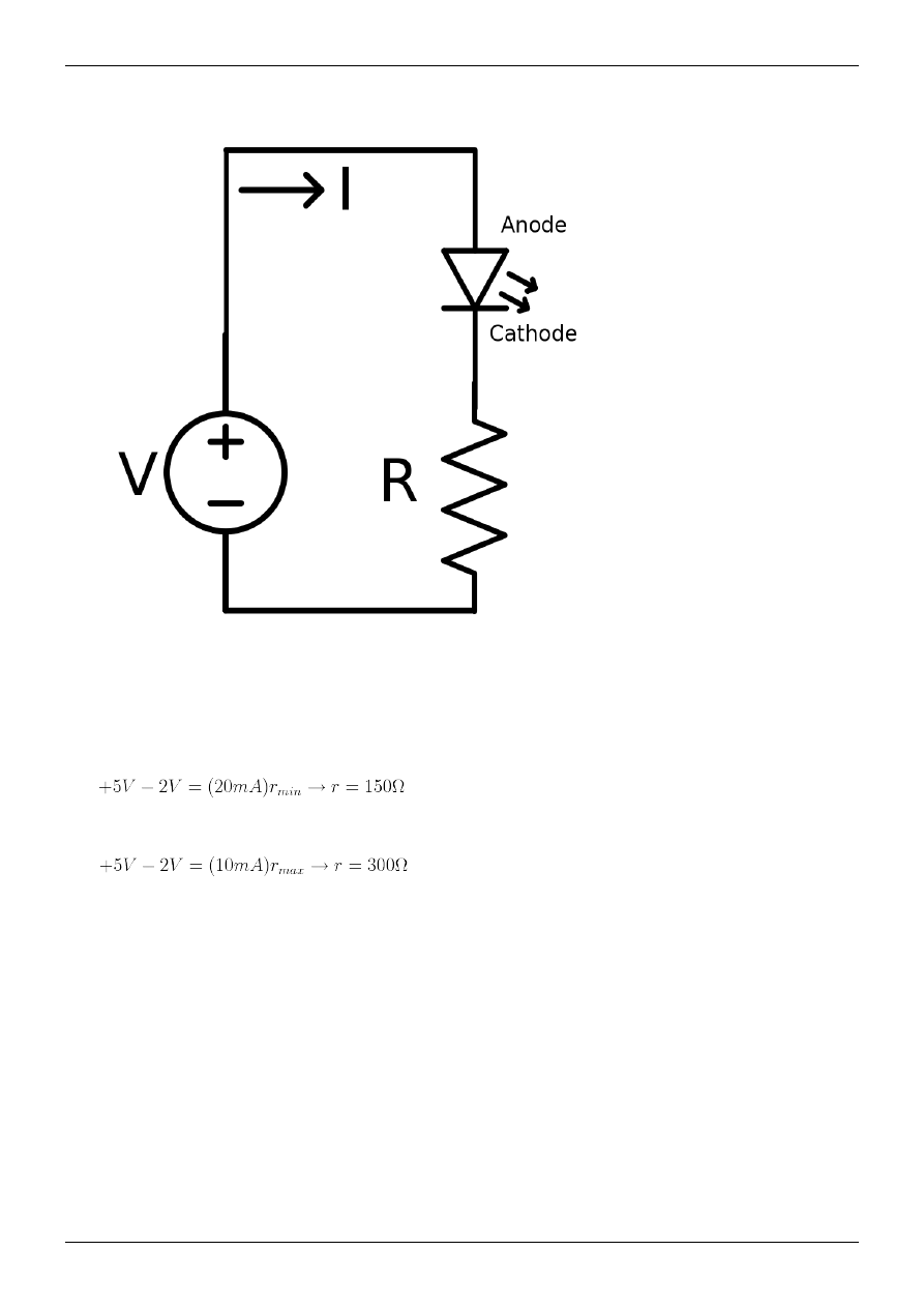
Embedded Systems/Low-Voltage Circuits
64
Example: Lighting LEDs
As a more complex example we would like to light a LED (light-emitting diode) from an output pin on an embedded
computer. Consider that our output pin can source 20mA at +5V. Our LED is green, which implies a forward voltage
drop of about 2 V. However, we also need to consider that our LED requires at least 10mA to light, and our LED can
not exceed +20 mA. If the current through the LED gets too high, the LED could pop (it's an actual pop, cover your
eyes).
Using ohm's law on the pin, we can find the minimum resistance for the circuit:
Now, if we use Ohm's law on the diode, we can figure out the maximum resistance (the resistance that makes the
LED not light up).
So we know that our resistance, r, needs to be between 150 and 300 Ohms. Any less than that, and we can
permanently destroy the LED or the microcontroller (or probably both). Any more than that, and no damage is done,
but the LED will be too dim to see.
further reading

Embedded Systems/High-Voltage Circuits
65
Embedded Systems/High-Voltage Circuits
Often we use embedded systems to control high-power devices. For example, maybe we want to program a
microcontroller to turn on and off standard light bulbs.
As we discussed earlier, typical microcontroller output pins switch between 0 V and 5 V, and can drive a maximum
of 0.025 A. But a typical light bulb requires 120 VAC at 0.5 A to turn on. We can't connect the microcontroller up to
the 120 VAC directly.
[1]
What do we do?
Transistors and Relays
Some transistors, known as "Power Transistors", can control a high voltage source using a lower voltage control
signal. There is also a type of electromechanical device known as a relay that can also be used to control a high
voltage source with a relatively small control current. Both of these tools can be used to control the flow of a
high-power electrical flow with an embedded computer.
Occasionally we need to use multiple stages of amplification. To turn on a large motor, we need a large relay -- but
to turn on the large relay, we need a power transistor -- but to turn on the large transistor, we need at least a small
transistor -- finally, we turn on the small transistor with the microcontroller output pin.
Isolation
When working with embedded systems, or any expensive piece of equipment, we often find that it is a good idea to
isolate the expensive components from the high power components. We do this through a technique called isolation.
Isolation, in essence, is how we keep the high current and/or high voltages out of low-current, low-voltage devices.
There are several types of isolators.
The "isolation barrier" is an imaginary line between the high-current or high-voltage device on one side, and
low-current, low-voltage devices on the other side.
• Transformers are used to transfer power from one side of the isolation barrier to the other
• optoisolators are used to transfer signals across an isolation barrier from one low-power device to another
low-power device
• relays allow a microcontroller on one side of the isolation barrier to switch on and off high-power devices on the
other side.
Transformers
Transformers use magnetic fields to move a voltage from one coil to another (over simplification). There is no direct
wire connection between the input and the output terminals, and therefore transformers can help to prevent spikes on
one side from damaging expensive equipment on the other.
Opto-Isolators
Opto-Isolators are the ultimate in isolation
. One half of the Opto-Isolator (OI) is an LED. The circuit
connected to that side turns the light on and off. The other half of the optoisolator is a phototransistor. When the light
is on, the phototransistor absorbs the light, and acts like a closed switch. When the light is off, the phototransistor
acts like an open switch. Because light is used instead of electricity, and because the light can only go in one
direction (from LED to phototransistor), they provide a very high level of reliable isolation.
The hardware MIDI interface is an example of a good opto-isolator interface.

Embedded Systems/High-Voltage Circuits
66
Relays
Relays can also be used to isolate, because they act very similarly to transformers. The current flow in one wire is
controlled by a magnetic field, generated by a second wire.
A relay controls whether electrons flow or not, by allowing a small current to the input coil producing a magnetic
field in which operates the switch.
references
[1] (1) Occasionally someone does accidentally connect an integrated circuit to 120 V. The integrated circuit immediately self-destructs. If you're
lucky, it cracks in half and lets off a small puff of smoke. If you're unlucky, it will still look like a good chip, leading to hours of frustration
trying to figure out why the system isn't working.
For further reading
• SCRs and triacs include several power transistors in a convenient package, and often cost less than buying
equivalent transistors seperately.
• So-called "solid-state relays" (Wikipedia:SSR) are a convenient combination of an opto-isolator and some power
transistors. Some SSRs include a Wikipedia:Zero cross circuit.

67
Particular Microprocessor Families
Embedded Systems/Particular Microprocessors
This module of Embedded Systems is a very brief review of the most popular microprocessor families used in
embedded systems. We will go into more detail in the next few modules. Each one of these microprocessor families
has an entire module dedicated to that family of processors.
The microprocessor families we will discuss are:
• Atmel AVR32
• Microchip PIC Microcontroller (this family includes the code-compatible Parallax SX chips) 8 bit
• Microchip dsPIC microcontroller 16 bit: review: Circuit Cellar: "Are You Up for 16 Bits? A look at Microchip's
Family of 16-Bit Microcontrollers
by Jeff Bachiochi 2007; example application: µWatch D-I-Y open source
• The Zilog Z8 Series (Z8, Z8encore, Z8XP)
• Cypress PSoC Microcontroller
• Texas Instruments MSP430 microcontrollers 16 bit
• ARM Microprocessors (this family includes the Philips LPC210x ARM microcontrollers, the discontinued Intel
w:StrongARM, Atmel AT91RM9200, and the Intel XScale microprocessors )
brief selection guide
For many embedded systems, any of these microcontrollers would be more than adequate.
• TI MSP430 has the lowest power consumption. In sleep mode, 0.3 µW = 3 V * 0.1 µA. Some chips in 2xx and
4xx series include 12-bit DACs.
• The Cypress PSoC has more than one true analog output. Using sleep mode, power consumption as low as 21 µW
with a PWM output and some low-pass filtering.) Most Cypress PSoC microcontrollers come in both DIP and
SMT versions.
• Many of these series include microcontrollers with integrated 10 bit ADCs, but Atmel AVR 8 bit series (as of
early 2006) had the lowest-price chip that included such an ADC, as well as another chip with the lowest
cost/ADC. Most Atmel AVR 8 bit microcontrollers come in both DIP and SMT versions.
• If you need a very tiny chip, the Atmel AVR, PIC, and Freescale microcontroller lines all include tiny 8-pin SOIC
microprocessors.
• If you want a 32 bit processor, some Philips ARM processors and Freescale Coldfire processors are now under $5
for one. (only comes in LQFP64 ?). The only (?) 32 bit processor currently being manufactured in a DIP package
is the Parallax Propeller (w:Parallax Propeller) -- $13 for one.
• Many people and several commercial products run Linux on a XScale microprocessor or a Atmel AT91RM9200
(ARM core), without a heatsink or fan. Linux has also been ported to the Atmel AVR32 AP7 family [4] (only
comes in a 208-pin VQFP). Linux has also been ported to Freescale 68k/ColdFire processors. I don't think Linux
has been ported to any of the other processors mentioned above.

Embedded Systems/Particular Microprocessors
68
USB interface
Main page: Serial Programming:USB Technical Manual
(FIXME: very incomplete)
standard PC as host, microcontroller as device
There are a variety of ways to connect a microcontroller to a USB host.
• Some microcontrollers (such as some 18x series PICmicro, 24x94 series (x = 7, 8, 9) PSoC and some Philips
ARM microcontrollers and some Atmel ARM microcontrollers and the Freescale MC9S08JS16) that have a
built-in "Full Speed" USB device interface.
• practically all microcontrollers have a UART. You can add a USB adapter
that interfaces between that UART
and USB, such as some based on the CP2102 chip
and some based on the FTDI chips
. Most of these
adapters are designed to have the microcontroller at the device end, and a PC on the host end. These adapters are
full speed (12Mbps) USB devices, but don't expect them to be fast, most of them emulate a serial port with baud
rates up to about 1 Mbps.
• Many microcontrollers (such as the Atmel ATmega16) can be programmed to be a Low speed USB device with a
few external passive components [8].
microcontroller as host, connecting to some USB device
There are a variety of ways to connect a microcontroller to a USB device.
• practically all microcontrollers have a UART, and some USB adapters[9] [10] can be set up with a
microcontroller as the host, and some USB device (a mouse, keyboard, or flash drive) on the device end.
• a few microcontrollers (such as the Parallax Propeller) can be programmed to talk to a few USB peripherals with
a few external passive components [11].
microcontroller as both a device (connected to a standard PC) and a host (connected to one
or more USB devices)
How ? ... USB on-the-go (OTG) defines a single socket that automatically switches between host and device ... for
example, a camera with a single USB socket that acts as a device when plugged into a PC (for uploading photos), but
acts like a host when plugged into a printer (for printing photos directly without a PC) ...
[12]
[13]
• The LUFA library allows the USB-enabled AVR microcontrollers to act as a USB Host, slave or OTG
device.[14]
• Most Atmel 32-bit AVR UC3 microcontrollers support full-speed (12 Mbps) USB 2.0 with USB Host, slave, or
On-The-Go (OTG) capability
other details on USB
For more details on USB, see the Serial Programming:USB Technical Manual.
Further reading
• Instructables: "How to choose a MicroController"
by westfw
• Once you've picked out a processor, you'll want to know Embedded Systems/Where To Buy it.
• Robotics: Single Board Computers discusses "processor modules" that include the CPU and a few support chips
in a convenient package.
• Getting started with microcontrollers
, part of the "Microcontroller Primer FAQ" by Russ Hersch
• microcontrollers for wireless sensor network devices

Embedded Systems/Particular Microprocessors
69
• "PIC vs. AVR"
"OK, I know what you people want. You want ultimate fighting, embedded E.E. style. You
want to know WHICH IS BETTER, PIC OR AVR?"
• CNCzone: "Microchip vs Atmel"
• PSoC Developer "PSoC VS PIC/AVR/ATMEL/8051"
has a brief comparison review of a few Freescale,
Microchip, and Cypress CPUs.
References
[1] http:/
[2] http:/
[3] http:/
[4] http:/
[5] http:/
RS232_RS485_USB_Converter_Board
[6] http:/
[7] http:/
[8] http:/
Building_a_USB_sensor_interface
[9] http:/
[10] http:/
[11] http:/
its-alive-bit-banging-full-speed-usb-host-for-the-propeller/
[12] "Understanding USB On-The-Go" (http:/
[13] "USB On-The-Go (OTG) Basics - AN1035" (http:/
[14] http:/
[15] http:/
How-to-choose-a-MicroController/
[16] http:/
[17] http:/
[18] http:/
[19] http:/
[20] http:/

Embedded Systems/Intel Microprocessors
70
Embedded Systems/Intel Microprocessors
When talking about Intel microprocessors, the first words that come to mind might be "Pentium" or "Celeron", or
any of the other high-performance, expensive PC chips that are on the market today. However, Intel maintains a very
impressive list of legacy parts that can be adapted for embedded systems. The beauty of using these microprocessors
is that they are frequently very cheap, and they will all use the standard x86 assembly language, so that developers
can program, assemble, and test from the comfort of a PC.
8086 and 80186
8086 and 80186 processors are available in heavily integrated packages. They are usually available in DIP form, and
are relatively cheap (10$ or 15$ range). These processors might not be as good as an 8051 in an embedded
environment, but the ease of programming, and the familiarity that many programmers will feel for these chips can
more then make up for the cost.
i386 Embedded Processors
The i386 microprocessor is a modified form of the Intel 80386 microprocessor with a few notable differences: an
integrated FPU (originally wasnt standard until th 80486), and a variety of different, small form-factors. One of the
major benefits of an i386 microprocessor is that it can be programmed easily using most standard C compilers and
x86 assembly language. In fact, many times no additional settings need to be changed in the compiler, except maybe
to not link to the standard libraries on the host system.
i386 processors are 32 bit processors, and are frequently very economical choices when a 32bit processor is required.
Also, i386 processors frequently have very low power consumption, and generate very little heat. Remember, Intel
has been working on this architecture and the general design of this chip continuously for many years now.
X-Scale Embedded Processors
The X-Scale processor is an ARM based device, designed for embedded systems requiring high performance with
low power consumption, such as PDA's.
Other Chips
Intel does sell embedded varieties of all its chips, from the 486 up to the Pentium 4. Keep in mind, however, that
these chips have all the power of their PC cousins, but in a smaller package. Therefore, it can be expected that they
will all be considerably more expensive then the desktop chips. Also, with some of the higher performance chips
(pentium and up), since the size has been aggressively reduced, and because they have been highly integrated for
embedded environments, heat can become an issue (meaning you will need to invest in fans and heat sinks as well).
Further reading
• ARM
• x86 Assembly

Embedded Systems/PIC Microcontroller
71
Embedded Systems/PIC Microcontroller
Manufactured by Microchip, the PIC ("Programmable Intelligent Computer" or "Peripheral Interface Controller" )
microcontroller is popular among engineers and hobbyists alike. PIC microcontrollers come in a variety of "flavors",
each with different components and capabilities.
Many types of electronic projects can be constructed easily with the PIC family of microprocessors, among them
clocks, very simple video games, robots, servo controllers, and many more. The PIC is a very general purpose
microcontroller that can come with many different options, for very reasonable prices.
Other microprocessors in this family include the Parallax SX, the Holtek HT48FxxE Series
, and some
"PIC-on-a-FPGA" implementations.
History
A long time ago General Instruments produced a chip called the PIC1650, described as a Programmable Intelligent
Computer. This chip is the mother of all PIC chips, functionally close to the current 16C54. It was intended as a
peripheral for their CP1600 microprocessor. Maybe that is why most people think PIC stands for Peripheral Interface
Controller. Microchip has never used PIC as an abbreviation, just as PIC. And recently Microchip has started calling
its PICs microcontrollers PICmicro MCU's.
Which PIC to Use
How do you find a PIC that is right for you out of nearly 2000 different models of PIC microcontrollers?
Rule Number 1: only pick a microprocessor you can actually obtain. PICs are all similar, and therefore you don't
need to be too picky about which model to use.
If there is only 1 kind of PIC available in your school storeroom, use it. If you order from a company such as Newark
of time in creating your project.
Recommended "first PIC"
At one time, the PIC16F84 was far and away the best PIC for hobbyists. But Microchip, Parallax, and Holtek are
now manufacturing many chips that are even better.
I'd like a list of the top 4 or so PIC recommendations, and *why* they were recommended, so that when
better/cheaper chips become available, it's easy to confirm and add them to the list.
(Summarizing PICList Beginners checklist for PIC Microcontrollers
, PIC Elmer 160: Appendix "A": "Other
PICs" 2003
:)
PIC: Select a chip and buy one
Many people recommend the following PICs as a good choice for the "first PIC" for a hobbyist:
• PIC18F4620 -- has 13 analog inputs -- Wouter van Ooijen recommends that hobbyists use the largest and most
capable chip available[6], and this is it (as of 2006-01). ~$9
• PIC16F877A -- the largest chip of the 16F87x family; has 8 analog inputs -- recommended by Wouter (#2);
AmQRP; PICList. ~$8
• PIC16F88 -- has 7 analog inputs -- recommended by AmQRP; SparkFun
. ~$5
• PIC16F628 -- Cheaper than the PIC16F84A, with a built-in 4MHz clock and a UART, but lacks any analog inputs
-- recommended by Wouter (#3); AmQRP -- ~$4
• PIC16F1936 -- 11 ch, 10-bit ADC; two indirect pointer registers; XLP (extreme low power) ... recommended by
some people on the PIClist as a faster, better, cheaper replacement for the 16F877. -- ~$3

Embedded Systems/PIC Microcontroller
72
Of the many new parts Microchip has introduced since 2003, are any of them significantly better for hobbyists in
some way than these chips ?
There are several different "families":
More selection tips
• The "F" Suffix implies that the chip has reprogrammable Flash memory.
PIC10F -- in super-tiny 6 pin packages
PIC12F -- in tiny 8-pin packages
PIC14F
PIC16F
PIC18F
dsPIC30F
• The "C" suffix implies that the chip uses EPROM memory. A few of these chips can be erased with an
Ultra-Violet eraser. But most of these chips are specifically made so that once you write it you can't change it --
it's OTP (one-time programmable).
PIC12C
PIC16C
PIC17C
PIC18C
Each family has one "full" member with all the goodies and a subset of variant members that lack one thing or
another. For prototyping, we generally use the "full" version to make sure we can get the prototype working at all.
During prototyping we want to tweak code, reprogram, and test, over and over until it works. So we use one of the
above "Flash" families, not the "OTP" families.
Each member of each family generally comes in several different packages. Hobbyists generally use the plastic dual
inline package (often called DIP or PDIP) because it's the easiest to stick in a solderless breadboard and tinker with.
(The "wide-DIP" works just as well). They avoid using ceramic dual inline package (CDIP), not because ceramic is
bad (it's just as easy to plug into a solderless breadboard), but because the plastic parts work just as well and are
much cheaper.
(Later, for mass production, we may figure out which is the cheapest cut-down version that just barely has enough
goodies to work, and comes in the cheapest package that has just barely enough pins for this particular application ...
perhaps even a OTP chip).
And then each different package, for each member of each family, comes in both a "commercial temperature range"
and a "industrial temperature range".

Embedded Systems/PIC Microcontroller
73
PIC 16x
The PIC 16 family is considered to be a good, general purpose family of PICs. PIC 16s generally have 3 output ports
to work with. Here are some models in this family that were once common:
1. PIC 16C54 - The original PIC model, the 'C54 is available in an 18 pin DIP, with 12 I/O pins.
2. PIC 16C55 - available in a 28-pin DIP package, with 20 available I/O pins
3. PIC 16C56 - Same form-factor as the 'C54, but more features
4. PIC 16C57 - same form-factor as the 'C55, but more features
5. PIC 16C71 - has 4 available ADC, which are mapped to the same pins as Port A (dual-use pins).
6. PIC 16C84 - has the ability to erase and reprogram in-circuit EEPROMs
Many programs written for the PIC16x family are available for free on the Internet.
Flash-based chips such as the PIC16F88 are far more convenient to develop on, and can run code written for the
above chips with little or no changes.
PIC 12x
The PIC 12 series are all very small chips, with 8 pins, and 4 available I/O pins. These are used only when space is a
huge factor, and the PIC doesn't have many responsibilities
PIC 18x
The PIC 18x series are available in a 28 and 40-pin DIP package. They have more ports, more ADC, etc... PIC 18s
are generally considered to be very high-end microcontrollers, and are even sometimes called full-fledged CPUs.
Microchip is currently (as of 2007) producing 6 Flash microcontrollers with a USB interface. All are in the PIC18Fx
family. (The 28 pin PIC18F2450, PIC18F2455, PIC18F2550; and the 40/44 pin PIC18F4450, PIC18F4455,
PIC18F4550 ).
The PIC Stack
The PIC stack is a dedicated bank of registers (separate from programmer-accessible registers) that can only be used
to store return addresses during a function call (or interrupt).
• 12 bit: A PIC microcontroller with a 12 bit core (the first generation of PIC microcontrollers) ( including most
PIC10, some PIC12, a few PIC16 ) only has 2 registers in its hardware stack. Subroutines in a 12-bit PIC program
may only be nested 2 deep, before the stack overflows, and data is lost. People who program 12 bit PICs spend a
lot of effort working around this limitation. (These people are forced to rely heavily on techniques that avoid
using the hardware stack. For example, macros, state machines, and software stacks).
• 14 bit: A PIC microcontroller with a 14 bit core (most PIC16) has 8 registers in the hardware stack. This makes
function calls much easier to use, even though people who program them should be aware of some remaining
gotchas [9].
• 16 bit: A PIC microcontroller with a 16 bit core (all PIC18) has a "31-level deep" hardware stack depth. This is
more than deep enough for most programs people write.
Many algorithms involving pushing data to, then later pulling data from, some sort of stack. People who program
microprocessors often share a single stack for both subroutine return addresses and this "stack data").
Call-tree analysis can be used to find the deepest possible subroutine nesting used by a program. (Unless the program
uses w:recursion). As long as the deepest possible nesting of the "main" program, plus the deepest possible nesting
of the interrupt routines, give a total sum less than the size of the stack of the microcontroller it runs on, then
everything works fine. Some compilers automatically do such call-tree analysis, and if the hardware stack is

Embedded Systems/PIC Microcontroller
74
insufficient, the compiler automatically switches over to using a "software stack". Assembly-language programmers
are forced to do such analysis by hand.
What else do you need
Compilers, Assemblers
Versions of BASIC, C, Forth, and a few other programming languages are available for PICmicros. See Embedded
downloaders
You need a device called a "downloader" to transfer compiled programs from your PC and burn them into the
microcontroller. (Unfortunately "programming" has 2 meanings -- see
Embedded_Systems/Terminology#programming).)
There are 2 styles of downloaders. If you have your PIC in your system and you want to change the software,
• with a "IC programmer" style device, you must pull out the PIC, plug it into the "IC programmer", reprogram,
then put the PIC back in your system.
• with a "in circuit programmer" style device (ICSP), you don't touch the PIC itself -- you plug a cable from the
programmer directly into a header that you have (hopefully) placed next to the PIC, reprogram, then unplug the
cable.
An (incomplete) list of programmers includes:
• In Circuit Programmer for PIC16F84 PIC16F84 Programmer
• IC Programmer ICProg
Programs : 12Cxx, 16Cxxx, 16Fxx, 16F87x, 18Fxxx, 16F7x, 24Cxx, 93Cxx, 90Sxxx,
59Cxx, 89Cx051, 89S53, 250x0, PIC, AVR , 80C51 etc.
• Many other programmers are listed at MassMind
Many people prefer to use a "bootloader" for programming whenever possible. Bootloaders are covered in detail in
chapter ../Bootloaders and Bootsectors/ .
Power Supply
The most important part of any electronic circuit is the power supply. The PIC programmer requires a +5 volt and a
+13 volt regulated power supply. The need for two power supplies is due to the different programming algorithms:
• High Power Programming Mode - In this mode, we enter the programming mode of the PIC by driving the
RB7(Data) and RB6(CLOCK) pins of the PIC low while driving the MCLR pin from 0 to VCC(+13v).
• Low Power Programming Mode - This alogrithm requires only +5v for the programming operation. In this
algorithm, we drive RB3(PGM) from VDD to GND to enter the progamming mode and then set MCLR to
VDD(+5v).
This is already taken care of inside the PIC burner hardware. If you are curious as to how this is done, you might
want to look at the various PIC burner hardware schematics online.
[13]
[14]
Oscillator Circuits
The PIC microcontrollers all have built-in RC oscillator circuits available, although they are slow, and have high
granularity. External oscillator circuits may be applied as well, up to a maximum frequency of 20MHz. PIC
instructions require 4 clock cycles for each machine instruction cycle, and therefore can run at a maximum effective
rate of 5MHz. However, certain PICs have a PLL (phase locked loop) multiplier built in. The user can enable the
Times 4 multiplier, thus yielding a virtual oscillator frequency of 4 X External Oscillator. For example, with a
maximum allowable oscillator of 16MHz, the virtual oscillator runs at 64MHz. Thus, the PIC will perform 64 / 4 =

Embedded Systems/PIC Microcontroller
75
16 MIPS (million instructions per second). Certain pics also have built-in oscillators, usually 4Mhz for precisely
1MIPS, or a low-power imprecise 48Khz. This frees up to two I/O pins for other purposes. The pins can also be used
to produce a frequency if you want to syncrhonize other hardware to the same clock as one PIC's internal one.
programming
Continue with Embedded Systems/PIC Programming.
Further reading
There is a lot of information about using PIC microcontrollers (and electronics design in general) in the PICList
archives. If you are really stumped, you might consider subscribing to the PICList, asking your question ... and
answering someone else's question in return. The PICList archives are hosted at MassMind
• RC Airplane/RCAP discusses a project that uses a PIC16F876A.
• the Parallax SX FAQ
: the original manufacturer's web site
• Getting Starting with PICmicro controllers
by Wouter van Ooijen
• "The PIC 16F628A: Why the PIC 16F84 is now obsolete."
• "The PIC 16F88: Why the PIC 16F84 is now Really obsolete."
• "Free PIC resources and projects with descriptions, schematics and source code."
• "Programming PICmicros in the C programming language"
• "Programming PICmicros in other programming languages: Forth, JAL, BASIC, Python, etc."
• The "8-bit PIC® Microcontroller Solutions brochure"
describes how big the PIC hardware stack is in each
PIC microcontroller family, and other major differences between families.
[1] http:/
[2] http:/
[3] http:/
[4] http:/
[5] http:/
[6] http:/
[7] http:/
[8] http:/
[9] http:/
[10] http:/
[11] http:/
[12] http:/
[13] "PIC Microcontroller Programmers" (http:/
[14] "Choosing a PIC programmer" (http:/
best-microcontroller-projects.
[15] http:/
[16] http:/
[17] http:/
idcplg?IdcService=SS_GET_PAGE&
[18] http:/
[19] http:/
[20] http:/
best-microcontroller-projects.
[21] http:/
[22] http:/
[23] http:/
• Micro&Robot - 877 (http:/
asp): robot kit
with self-programmable PIC Microcontroller! You don't need a PIC programmer.
• Programming the PIC16f628a with SDCC (http:/
): An occasionally-updated list
of examples demonstrating how to use the PIC's peripherals and interface with other devices with the free SDCC

Embedded Systems/PIC Microcontroller
76
pic compiler.
Embedded Systems/8051 Microcontroller
The Intel 8051 microcontroller is one of the most popular general purpose microcontrollers in use today. The success
of the Intel 8051 spawned a number of clones which are collectively refered to as the MCS-51 family of
microcontrollers, which includes chips from vendors such as Atmel, Philips, Infineon, and Texas Instruments.
About the 8051
The Intel 8051 is an 8-bit microcontroller which means that most available operations are limited to 8 bits. There are
3 basic "sizes" of the 8051: Short, Standard, and Extended. The Short and Standard chips are often available in DIP
form, but the Extended 8051 models often have a different form factor, and are not "drop-in compatible". All these
things are called 8051 because they can all be programmed using 8051 assembly language, and they all share certain
features (although the different models all have their own special features).
Some of the features that have made the 8051 popular are:
• 8-bit data bus
• 16-bit address bus
• 32 general purpose registers each of 8 bits
• 16 bit timers (usually 2, but may have more, or less).
• 3 internal and 2 external interrupts.
• Bit as well as byte addressable RAM area of 16 bytes.
• Four 8-bit ports, (short models have two 8-bit ports).
• 16-bit program counter and data pointer
8051 models may also have a number of special, model-specific features, such as UARTs, ADC, OpAmps, etc...
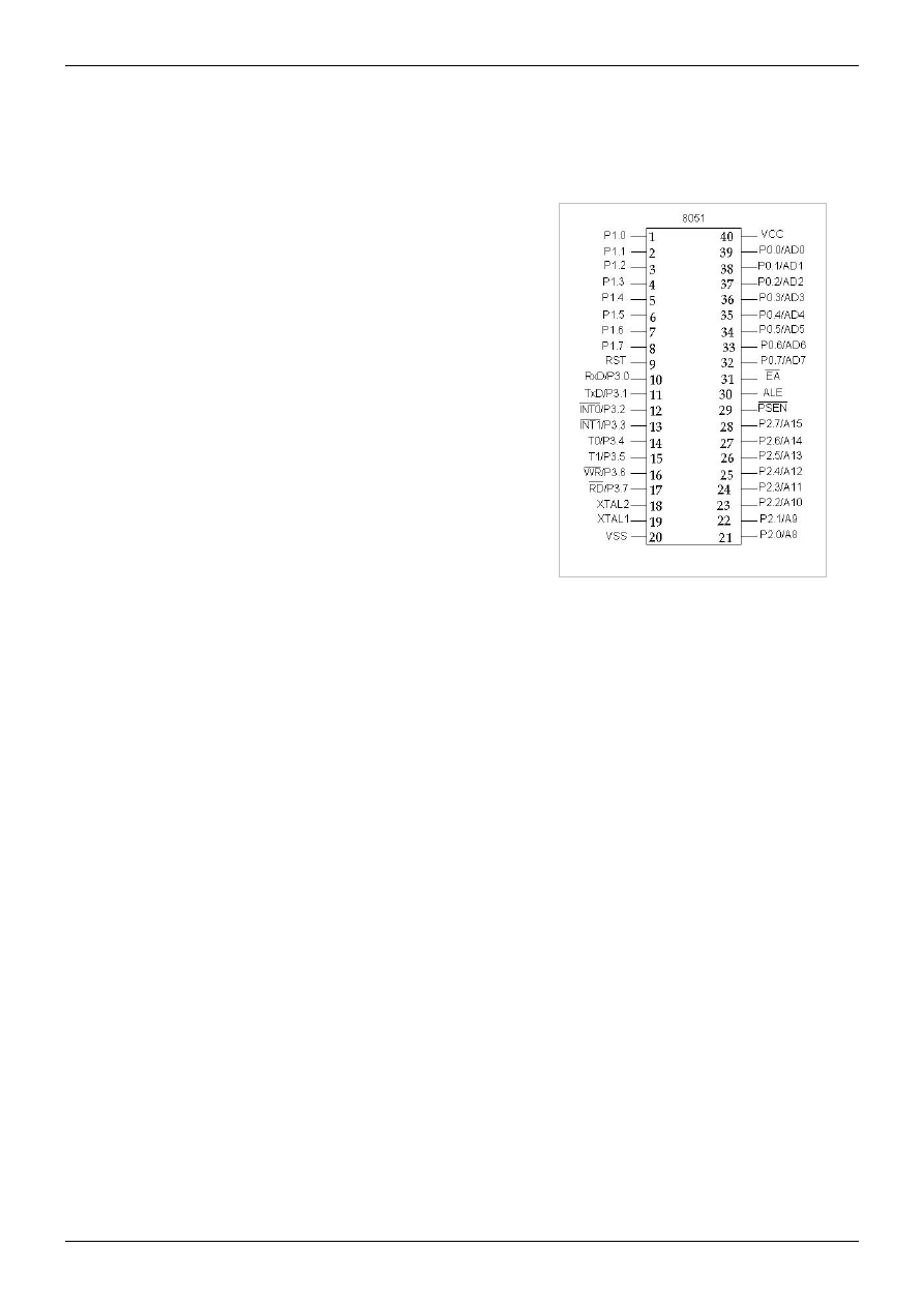
Embedded Systems/8051 Microcontroller
77
Typical applications
8051 chips are used in a wide variety of control systems, telecom applications, robotics as well as in the automotive
industry. By some estimations, 8051 family chips make up over 50% of the embedded chip market.
Pin diagram of the 8051 DIP
Basic Pins
PIN 9: PIN 9 is the reset pin which is used reset the microcontroller’s
internal registers and ports upon starting up. (Pin should be held high
for 2 machine cycles.)
PINS 18 & 19: The 8051 has a built-in oscillator amplifier hence we
need to only connect a crystal at these pins to provide clock pulses to
the circuit.
PIN 40 and 20: Pins 40 and 20 are VCC and ground respectively. The
8051 chip needs +5V 500mA to function properly, although there are
lower powered versions like the Atmel 2051 which is a scaled down
version of the 8051 which runs on +3V.
PINS 29, 30 & 31: As described in the features of the 8051, this chip
contains a built-in flash memory. In order to program this we need to
supply a voltage of +12V at pin 31. If external memory is connected
then PIN 31, also called EA/VPP, should be connected to ground to
indicate the presence of external memory. PIN 30 is called ALE
(address latch enable), which is used when multiple memory chips are connected to the controller and only one of
them needs to be selected. We will deal with this in depth in the later chapters. PIN 29 is called PSEN. This is
"program select enable". In order to use the external memory it is required to provide the low voltage (0) on both
PSEN and EA pins.
Ports
There are 4 8-bit ports: P0, P1, P2 and P3.
PORT P1 (Pins 1 to 8): The port P1 is a general purpose input/output port which can be used for a variety of
interfacing tasks. The other ports P0, P2 and P3 have dual roles or additional functions associated with them based
upon the context of their usage.
PORT P3 (Pins 10 to 17): PORT P3 acts as a normal IO port, but Port P3 has additional functions such as, serial
transmit and receive pins, 2 external interrupt pins, 2 external counter inputs, read and write pins for memory access.
PORT P2 (pins 21 to 28): PORT P2 can also be used as a general purpose 8 bit port when no external memory is
present, but if external memory access is required then PORT P2 will act as an address bus in conjunction with
PORT P0 to access external memory. PORT P2 acts as A8-A15, as can be seen from fig 1.1
PORT P0 (pins 32 to 39) PORT P0 can be used as a general purpose 8 bit port when no external memory is present,
but if external memory access is required then PORT P0 acts as a multiplexed address and data bus that can be used
to access external memory in conjunction with PORT P2. P0 acts as AD0-AD7, as can be seen from fig 1.1
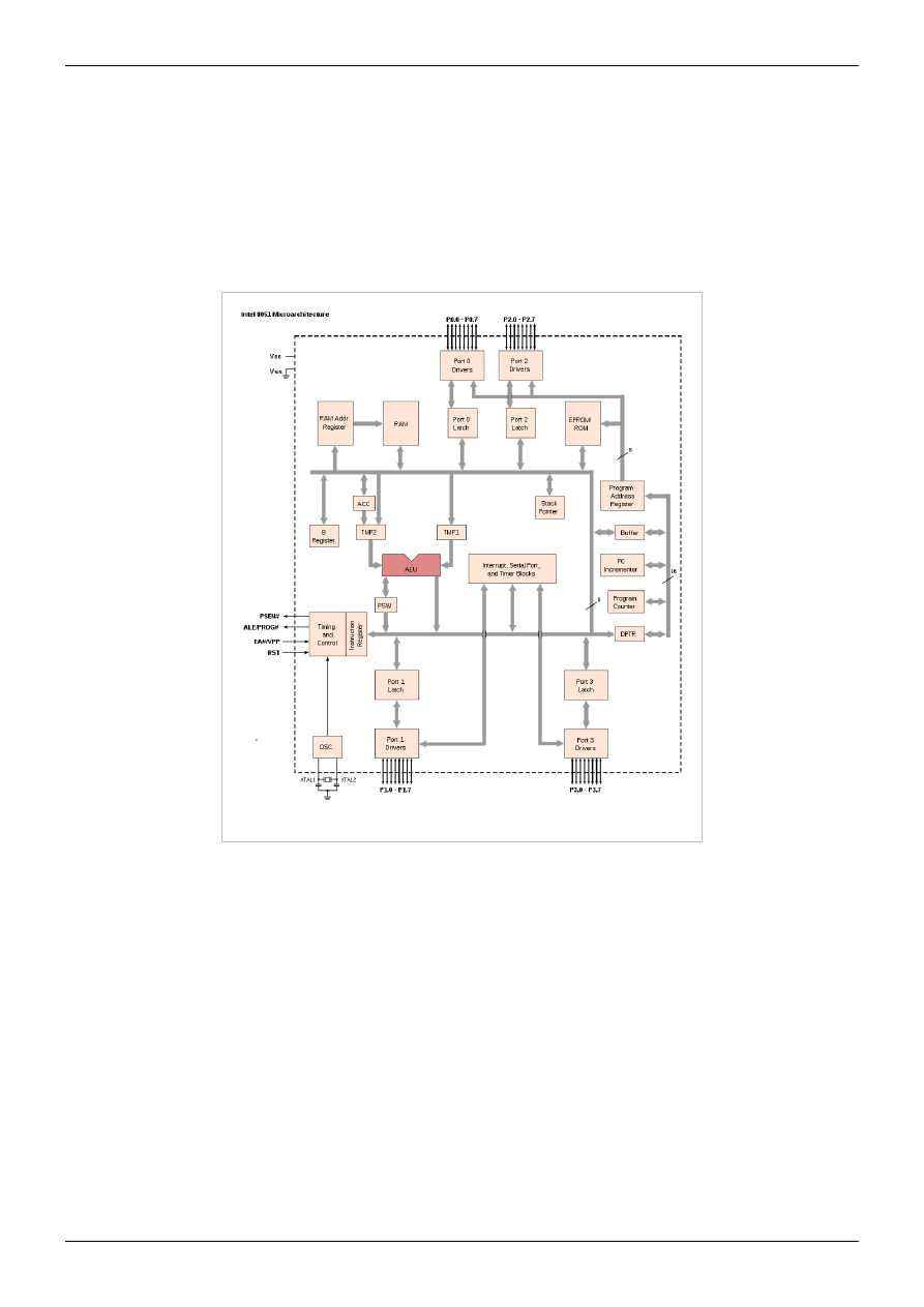
Embedded Systems/8051 Microcontroller
78
Oscillator Circuits
The 8051 requires the existence of an external oscillator circuit. The oscillator circuit usually runs around 12MHz,
although the 8051 (depending on which specific model) is capable of running at a maximum of 40MHz. Each
machine cycle in the 8051 is 12 clock cycles, giving an effective cycle rate at 1MHz (for a 12MHz clock) to
3.33MHz (for the maximum 40MHz clock).
Internal Architecture
Internal schematics of the 8051.
Data and Program Memory
The 8051 Microprocessor can be programmed in PL/M, 8051 Assembly, C and a number of other high-level
languages. Many compilers even have support for compiling C++ for an 8051.
Program memory in the 8051 is read-only, while the data memory is considered to be read/write accessible. When
stored on EEPROM or Flash, the program memory can be rewritten when the microcontroller is in the special
programmer circuit.

Embedded Systems/8051 Microcontroller
79
Program Start Address
The 8051 starts executing program instructions from address 0x00 in the program memory.
Direct Memory
The 8051 has 256 bytes of internal addressable RAM, although only the first 128 bytes are available for general use
by the programmer. The first 128 bytes of RAM (from 0x00 to 0x7F) are called the Direct Memory, and can be
used to store data.
Special Function Register
The Special Function Register (SFR) is the upper area of addressable memory, from address 0x80 to 0xFF. A, B,
PSW, DPTR are called SFR.This area of memory cannot be used for data or program storage, but is instead a series
of memory-mapped ports and registers. All port input and output can therefore be performed by memory mov
operations on specified addresses in the SFR. Also, different status registers are mapped into the SFR, for use in
checking the status of the 8051, and changing some operational parameters of the 8051.
General Purpose Registers
The 8051 has 4 selectable banks of 8 addressable 8-bit registers, R0 to R7. This means that there are essentially 32
available general purpose registers, although only 8 (one bank) can be directly accessed at a time. To access the other
banks, we need to change the current bank number in the flag status register.
A and B Registers
The A register is located in the SFR memory location 0xE0. The A register works in a similar fashion to the AX
register of x86 processors. The A register is called the accumulator, and by default it receives the result of all
arithmetic operations. The B register is used in a similar manner, except that it can receive the extended answers
from the multiply and divide operations. When not being used for multiplication and Division, the B register is
available as an extra general-purpose register.

Embedded Systems/Freescale Microcontrollers
80
Embedded Systems/Freescale Microcontrollers
Freescale Semiconductor (formally Motorola Semiconductor Products Sector) spun-off from Motorola in July 2004.
Freescale makes many microcontrollers (MCU's) and also a whole host of other devices such as sensors, DSP's and
memory, to name a few.
The Freescale Microcontrollers come in 5 families.
• 6800 descendents: 8 bit or 16 bit
• 68000 descendents: 32 bit
• MCORE: 32 bit
• PowerPC family: 32 bit
• ARM family: 32 bit. We discuss ARM core Freescale microcontrollers in another chapter, Embedded
8-bit MCUs
Freescale HC08
There are many variations on the HC08 CPU core; The 68HC908JL8 is one example. the HC908Jl3 offer 256 bytes
of RAM (random access memory) and 4K bytes of Flash ROM (Read only memory). The Hc08 cores offer a
maximum bus speed of 8MHz, a 20MHz crystal may be used as the external clock source(as the oscillator is
internaly divided by 4 to give 8MHz bus speed). Typical peripheral components of the microcontroller include:
• Two 16 bit, free running timers.
• SCI (serial communications interface,(RS232))
• 12 channel 8-bit Analogue to digital converters (A/D)
The HC08 microcontrollers are usually supplied in 28 pin or 32 pin DIL packages, but can also be obtained in
serface-mount SOIC footprints
16-bit MCUs
32-bit Embedded Processors
68k/ColdFire
The 68k family and the nearly-binary-compatible ColdFire family are 32 bit processors capable of running Linux.
There is a Debian Linux port to 68k processors with a MMU. A Debian Linux port to ColdFire processors with a
MMU is "in progress".
There are several ColdFire chips that, as of 2008, are available for under $5 (in qty 1). Those low-cost chips do not
include a MMU, and so cannot run a full version of Linux. w:uClinux runs on chips without a MMU, and has been
ported to some ColdFire chips[1] on platforms with at least 1 MB of RAM.
Yes, but does uClinux actually run on a chip that costs less than $5 ?
Most (all?) currently manufactured ColdFire and 68k chips are available only in surface mount packages, not in any
DIP package.

Embedded Systems/Freescale Microcontrollers
81
PowerPC
• First Generation: G1 (601)
• Second Generation: G2 (603, 603e, 604)
• Third Generation: G3 (750, 750CX, 750CX3, 750FX, 750GX)
• Fourth Generation: G4 (7400,7450)
further reading
• The 68HC12 discussion forum at EmbeddedRelated
is still pretty active, apparently because 68HC12 dev
boards (such as those from EVBplus
) are typically lower-cost than dev boards with most other
microcontrollers.
• EE Compendium: resources for using Freescale's HC12 family
References
[1] http:/
[2] http:/
[3] http:/
[4] http:/
Embedded Systems/Atmel AVR
The Atmel AVR
TM
is a family of 8-bit RISC microcontrollers produced by Atmel. The AVR architecture was
conceived by two students at the Norwegian Institute of Technology (NTH) and further refined and developed at
Atmel Norway, the Atmel daughter company founded by the two chip architects.
Memory
memory are on separate buses to allow faster access and increased capacity. The AVR uses internal memory for data
and program storage, and so does not require any external memory.
The four types of memories in a Atmel AVR are:
• Data memory: registers, I/O registers, and SRAM
• Program flash memory
• EEPROM
• Fuse bits
All these memories are on the same chip as the CPU core. Each kind of memory is separated from each other, in
different locations on the chip. Address 0 in data memory is distinct from address 0 in program flash and address 0 in
EEPROM.

Embedded Systems/Atmel AVR
82
Program Memory
All AVR microcontrollers have some amount of 16 bit wide non-volatile flash memory for program storage, from
1 KB up to 256 KB (or, 512-128K typical program words). The program memory holds the executable program
opcodes and static data tables. Program memory is linearly addressed, and so mechanisms like page banking or
segment registers are not required to call any function, regardless of its location in program memory.
AVRs cannot use external program memory; the flash memory on the chip is the only program memory available to
the AVR core.
The flash program memory can be reprogrammed using a programming tool, the most popular being those that
program the chip in situ and are called in-system programmers (ISP). Atmel AVRs can also be reprogrammed with a
high-voltage parallel or serial programmer, and via JTAG (again, in situ) on certain chips. The flash memory in an
AVR can be re-programmed at least 10,000 times.
Many of the newer AVRs (MegaAVR series) have the capability to self-program the flash memory. This
functionality is used mainly by bootloaders.
Data Memory
Data Memory includes the registers, the I/O registers, and internal SRAM.
The AVR has thirty-two general purpose eight-bit registers (R0 to R31), six of which can be used in pairs as
sixteen-bit pointers (X, Y, and Z).
All AVR microcontrollers have some amount of RAM, from 32 bytes up to several KB. This memory is byte
addressable. The register file (both general and special purpose) is mapped into the first addresses and thus
accessible also as RAM. Some of the tiniest AVR microcontrollers have only the register file as their RAM.
The data address space consists of the register file, I/O registers, and SRAM. The working registers are mapped in as
the first thirty-two memory spaces (0000
16
-001F
16
) followed by the reserved space for up to 64 I/O registers
(0020
16
-005F
16
). The actual usable SRAM starts after both these sections (address 0060
16
). (Note that the I/O
register space may be larger on some more extensive devices, in which case the beginning address of SRAM will be
higher.) Even though there are separate addressing schemes and optimized opcodes for register file and I/O register
access, they can still be addressed and manipulated as if they were SRAM.
The I/O registers (and the program counter) are reset to their default starting values when a reset occurs. The
registers and the rest of SRAM have initial random values, so typically one of the first things a program does is clear
them to all zeros or load them with some other initial value.
The registers, I/O registers, and SRAM never wear out, no matter how many times they are written.
External Data Memory
Some of the higher pin-count AVR microcontrollers allow for external expansion of the data space, addressable up
to 64 KB. When enabled, external SRAM is overlaid by internal SRAM; an access to address 0000
16
in the data
space will always resolve to on-chip memory. Depending on the amount of on-chip SRAM present in the particular
AVR, anywhere from 512 bytes to several KB of external RAM will not be accessible. This usually does not cause a
problem.
The support circuitry required is described in the datasheet for any device that supports external data memory, such
, in the "External Memory Interface" section. The support circuitry is minimal, consisting of a
'573 or similar latch, and potentially some chip select logic. The SRAM chip select may be tied to a logic level that
permanently enables the chip, or it may be driven by a pin from the AVR. For an SRAM of 32 KB or less, one
option is to use a higher-order address line to drive the chip select line to the SRAM.

Embedded Systems/Atmel AVR
83
EEPROM Storage
Almost all AVR microcontrollers have internal EEPROM memory for non-volatile data storage. Only the Tiny11
and Tiny28 have no EEPROM.
EEPROM memory is not directly mapped in either the program or data space, but is instead accessed indirectly as a
peripheral, using I/O registers. Many compilers available for the AVR hide some or all of the details of accessing
EEPROM. IAR's C compiler for the AVR recognizes the compiler-specific keyword __eeprom on a variable
declaration. Thereafter, a person writes code to read and write that variable with the same standard C syntax as
normal variables (in RAM), but the compiler generates code to access the EEPROM instead of regular data memory.
Atmel's datasheets indicate that the EEPROM can be re-written a minimum of 100,000 times. An application must
implement a wear-leveling scheme if it writes to the EEPROM so frequently that it will reach the write limit before it
reaches the expected lifetime of the device. AVRs ship from the factory with the EEPROM erased, i.e. the value in
each byte of EEPROM is FF
16
.
Many of the AVRs have errata about writing to EEPROM address 0 under certain power conditions (usually during
brownout), and so Atmel recommends that programs not use that address in the EEPROM.
Fuse Settings
A Fuse is an EEPROM bit that controls low level features and pin assignments. Fuses are not accessible by the
program; they can only be changed by a chip programmer. Fuses control features which must be set before the chip
can come out of reset and begin executing code.
The most frequently modified fuses include:
1. Oscillator/crystal characteristics, including drive strength and start-up time.
2. JTAG pins used for JTAG or GPIO
3. RESET pin used as a reset input, debugWire, or GPIO
4. Brown Out Detect (BOD) enable and BOD voltage trigger points
There is a also a fuse to enable serial in-system programming, which is set by default. If it is set incorrectly, the only
way to program the chip is by using a high-voltage programmer, such as the STK-500, AVR Dragon, or third-party
programmer. A developer is therefore cautioned to be careful when manipulating fuses.
Reset
The AVR's RESET pin is an active-low input that forces a reset of the processor and its integrated peripherals. The
line can be driven by an external power-on reset generator, a voltage supervisor (which asserts RESET when the
power supply voltage drops below a predefined threshold), or another component in a larger system. For example, if
the AVR is managing a few sensors and servos as part of a large integrated system, another controller might observe
some condition that justifies resetting the AVR; it could do so by asserting the AVR's RESET line.
reset periodically to prevent it from timing out. Failure to reset the watchdog timer is usually an indication that the
program code has failed (locked up, entered an infinite loop, or otherwise gone astray), and the processor should be
reset. On some AVRs the watchdog can be programmed to issue an interrupt instead of resetting the processor. This
functionality can be used to wake up the AVR from a sleep mode.
The RESET pin is used for in-system serial programming, as a GPIO, or for debugWIRE
TM
low pin count
debugging, depending on the chip and the programming of the fuse bits. If the reset functionality of that pin is
disabled, it cannot be recovered by in-system serial programming, and another method such as high-voltage
programming must be used.

Embedded Systems/Atmel AVR
84
Interrupts
AVRs support multiple interrupt sources, both internal and external. An interrupt could be from an internal
peripheral reaching a certain state (i.e. character received on UART), or from an external event like a certain level on
a pin. Each interrupt source causes a jump to a specific location in memory. That location is expected to contain
either a RETI (Return from Interrupt) instruction to essentially ignore the interrupt, or a jump to the actual interrupt
handler.
Most AVRs have at least one dedicated external interrupt pin (INT0). Older AVRs can trigger an interrupt on a high
or low level, or on a falling edge. Newer AVRs add more options, such as triggering on the rising edge or either
edge. Additionally, many of the newer AVRs implement pin-change interrupts for all pins in groups of eight,
eliminating the need for polling the pins. The pin-change interrupt handler must examine the state of the pins that are
associated with that interrupt vector, and determine what action to take.
Due to button bounce issues, it is considered poor design to connect a push button or other user input directly to an
interrupt pin; some debouncing or other signal conditioning must be interposed so that the signal from the button
does not violate the setup and hold times required on the interrupt pins.
General Purpose I/O Ports
General Purpose I/O, or GPIO, pins are the digital I/O for the AVR family. These pins are true push-pull outputs.
The AVR can drive a high or low level, or configure the pin as an input with or without a pull-up. GPIOs are
grouped into "ports" of up to 8 pins, though some AVRs do not have enough pins to provide all 8 pins in a particular
port, e.g. the Mega48/88/168 does not have a PortC7 pin. Control registers are provided for setting the data direction,
output value (or pull-up enabled), and for reading the value on the pin itself. An individual pin can be accessed using
bitwise manipulation instructions.
Each port has 3 control registers associated with it, DDRx, PORTx, and PINx. Each bit in those registers controls
one GPIO pin, i.e. bit 0 in DDRA controls the data direction for PortA0 (often abbreviated PA0), and bit 0 in
PORTA will control the data (or pullup) for PA0.
The DDR (Data Direction Register) controls whether the pin is an input or an output. When the pin is configured as
an output, the corresponding bit in the PORT register will control the drive level to the pin, high or low. When the
pin is configured as an input, the bit in the PORT register controls whether a pull-up is enabled or disabled on that
pin. The PIN (Port Input) register was read-only on earlier AVRs, and was used to read the value on the port pin,
regardless of the data direction. Newer AVRs allow a write to the PIN register to toggle the corresponding PORT bit,
which saves a few processor cycles when bit-banging an interface.
Timer/Counters
All AVRs have at least one 8-bit timer/counter. For brevity, a timer/counter is usually referred to as simply a timer.
Some of the Tiny series have only one 8-bit timer. At the high end of the Mega series, there are chips with as many
as six timers (two 8-bit and four 16-bit).
A timer can be clocked directly by the system clock, by a divided-down system clock, or by an external input (rising
or falling edge). Some AVRs also include an option to use an external crystal, asynchronous to the system clock,
which can be used for maintaining a real-time clock with a 32.768 kHz crystal.
The basic operation of a timer is to count up to FF
8
(or FFFF
16
), roll over to zero, and set an overflow bit, which may
cause an interrupt if enabled. The interrupt routine reloads the timer with the desired value in addition to any other
processing required.
The value of a timer can be read back at any time, even while it is running. (There is a specific sequence documented
in the datasheets to read back a 16-bit timer so that a consistent result is returned, since the AVR can only move 8

Embedded Systems/Atmel AVR
85
bits at a time.) A timer can be halted temporarily by changing its clock input to "disabled," then resumed by
re-selecting the previous clock input.
PWM
Many of the AVRs include a compare register for at least one of the timers. The compare register can be used to
trigger an interrupt and/or toggle an output pin (i.e. OC1A for Timer 1) when the timer value matches the value in
the compare register. This may be done separately from the overflow interrupt, enabling the use of pulse-width
modulation (PWM).
Some AVRs also include options for phase-correct PWM, or phase- and frequency-correct PWM.
The Clear Timer on Compare (CTC) mode allows for the timer to be cleared when it matches a value in the compare
register, before the timer overflows. Clearing the timer prior to overflow manipulates the timer resolution, allowing
for greater control of the output frequency of a compare match. It can also simplify the counting of an external event.
The ATtiny26 is unique in its inclusion of a 64 MHz high-speed PWM mode. The 64 MHz clock is generated from a
PLL, and is independent of, and asynchronous to, the processor clock.
Some AVRs also include complementary outputs suitable for controlling some motors. A dead-time generator
(DTG) inserts a delay between one signal falling and the other signal rising so that both signals are never high at the
same time. The high-end AT90PWM series allows the dead time to be programmed as a number of system clock
cycles, while other AVRs with this feature simply use 1 clock cycle for the dead time.
Output Compare Modulator
An Output Compare Modulator (OCM), which allows generating a signal that is modulated with a carrier frequency.
OCM requires two timers, one for the carrier frequency, and the second for the signal to be modulated. OCM is
available on some of the Mega series.
Serial Communication
AVR microcontrollers are in general capable of supporting a plethora of serial communication protocols and serial
bus standards. The exact types of serial communication support varies between the different members of the AVR
microcontroller family.
On top of support in hardware there is also often the option to implement a particular serial communication
mechanism entirely in software. Typically this is used in case a particular AVR controller does not support some
serial communication mechanism in hardware, the particular hardware is already in use (e.g. when two RS-232
interfaces are needed, but only one is supported in hardware), or the chip's hardware can't be used, because it shares
pins with other chip functions, and such a function is already in used for the particular hardware. The latter often
happens with the low-pincount AVRs in DIP packages.
Finally, there is also the possibility to use additional logic to implement a serial communication function. For
example, most AVRs don't support the USB bus (some later ones do so, however). When using an AVR which
doesn't support USB directly, a circuit designer can add USB functionality with a fixed-function chip such as the
FTDI232 USB to RS-232 converter chip, or a general-purpose USB interface such as the PDIUSB11. Adding
additional electronics is in fact necessary for some supported communication protocols, e.g. standard-compliant
RS-232 communication requires adding voltage level converters like the MAX232.
The number of serial communication possibilities supported by a particular AVR can be confusing at times, in
particular if the pins are shared with other chip functions. An intensive study of the particular AVR's datasheet is
highly recommended. The serial communication features most commonly to be found on AVRs are discussed in the
following sections.

Embedded Systems/Atmel AVR
86
Universal Synchronous Asynchronous Receiver Transmitter (USART)
Recent AVRs typically come with a Universal Synchronous Asynchronous Receiver Transmitter (USART) built-in.
A USART is a programmable piece of hardware which is capable of generating and decoding various serial
communication protocols. USART is an acronym from the following words:
Universal
Can be used in a lot of different serial communication scenarios
Synchronous
Can be used for synchronous serial communication (sender and receiver are synchronised by a particular clock
signal)
Asynchronous
Can be used for asynchronous serial communication (sender and receiver are not explicitly synchronised via a
clock signal, but synchronise on the data signal).
Receiver
The hardware in the AVR can receive serial data
Transmitter
The hardware can send serial data
Earlier AVRs had a UART that did not support synchronous serial communication, hence the absence of the "S" in
the acronym.
USARTs or UARTs work with logic voltage levels while e.g. the RS-232 protocol requires much different voltage
levels than the 5 V or 3.3 V supplies found on AVR circuits. The conversion from and to such voltage levels is
performed by an additional chip which is commonly called a line driver or line interface.
With the right line interface an AVR's USART can, for example, be used to communicate with RS-232, RS-485,
MIDI, LIN bus, or CANbus devices, to name some of the popular protocols.
See Robotics: Computer Control: The Interface: Networks for more details.
RS-232 Signalling
The RS-232 specification calls for a negative voltage to represent a "1" bit, and a positive voltage to represent a "0"
bit. The spec allows for levels from +3 to +15 V, and -3 to -15 V, but +/-12 V is commonly seen. The AVR does not
have the ability to drive a negative output voltage on any GPIO pin, and so a level converter, such as the MAX232,
is used to talk to PCs and strict RS-232 devices. See Serial Programming:RS-232 Connections for more detail on
RS-232 wiring.
RS-232 has a relatively short maximum cable length. For longer cabling distances, consider using RS-485 signaling
on your USART.

Embedded Systems/Atmel AVR
87
Two Wire Interface
TWI is a variant of Phillips' I²C bus interface. I²C consists of two wires, known as SDA (serial data) and SCL (serial
clock), which use open-drain drivers and therefore require pull-ups to a logic-1 state. I²C uses a common ground, so
all devices on the bus should be at the same ground potential to avoid ground loops. TWI uses 7 bit addressing,
which allows for multiple devices to connect to the bus.
Many TWI devices have at least the top four bits of the address hard-coded, and the remaining bits configurable by
some means such as connecting dedicated address pins to power or ground; this often allows for only 2-8 model X
devices on the bus. The AVR's TWI hardware can act as Master or Slave, and can meet the 400 kbit/s spec.
Serial Peripheral Interface (SPI)
SPI, the Serial Peripheral Interface Bus, is a master-slave synchronous serial protocol. This means that there is a
clock line which determines where the pulses are to be sampled, and that one of the parties is always in charge of
initiating communication. It uses at least three lines, which are called:
MISO
Master In Slave Out.
MOSI
Master Out Slave In.
SCK
Serial Clock.
Conceptually, SPI is a bidirectional shift register; as bits are shifted out on either MISO or MOSI, bits are shifted in
on the other line. The master always controls the clock.
An SPI slave has a Slave Select (SS) signal, which signals to the slave that it should respond to messages from the
master. SS is almost always active-low. If there is only one master and one slave, the slave's SS line could be tied
low, and the master would not need to drive it. If there are two or more slaves, then the master must use a separate
slave select signal to each slave. The downside of this approach is that the master can only address as many slaves as
it has extra outputs (without the use of a separate decoder).
Hardware Implementation The larger AVR microcontrollers have built-in SPI transceivers (from the ATmega8
upwards). The serial clock is derived from the processor clock, with several divisors available. The data length is
always 8 bits. The clock polarity and phase may be configured, leading to four possible combinations of when the
data is clocked in and out of the chip. This interface is very popular, and is widely available on a variety of other
processors and peripherals.
The pins used for the SPI bus are also used as a way of programming the chip via ISP (In System
Programming)(Except on the mega128).
Universal Serial Interface Some AVRs, particularly in the Tiny family, provide a Universal Serial Interface (USI)
instead of an SPI. The USI is capable of operating as an SPI, but also as an I2C controller, and with a little extra
effort, a USART. The bit length of the transfer is configurable, as is the clock driver. The clock can be driven by
software, by the timer 0 overflow, or by an external source.
Software Implementation SPI can be implemented using bit-banging of the I/O lines. An efficient implementation
of a slave can be done by connecting SCLK to an external interrupt source.
The datasheet for a particular AVR provides a block diagram of the SPI or USI controller on that chip.
Embedded Systems/Atmel AVR
88
Protocol Issues
SPI, RS-232, I
2
C, and other serial interfaces only define the method by which bits and bytes are transmitted; they
correspond to layer 1 in the OSI model, the physical layer. The bytes could be anything: temperature readings (in
Celsius or Fahrenheit, depending on your sensor), readings from a pressure sensor, control signals to turn off a
pump, or the bytes of a JPEG image. Some of this meaning may be assigned by the use of a serial communications
protocol.
A serial protocol must handle a wide variety of usage conditions, as well as provide for recovering from failures. For
example, if two sensors are connected to a single microcontroller (such as inside and outside temperature), the
protocol provides a way for the receiver on the other end of the serial line to discern which reading belongs to which
sensor. If a cable is unplugged during transmission, or a byte is lost due to line noise, the protocol can provide a way
to re-synchronize the transmitter and the receiver.
The Serial Programming wikibook contains more discussion of serial protocols.
Analog Interfaces
Analog to Digital
Analog to digital conversion uses digital number to represent the proportion of the analog signal sampled. For
example, by applying a 3 V to the input of an ADC with a full-scale range of 5 V, will result as a digital output of
60% of the full range of the digital output. The digital number can be represented in 8 or 10 bits by the ADC. An 8
bit converter will provide output from 0 to
, or 255. 10 bits will provide output from 0 to
.
10 bit sample:
in ADCH:ADCL or
8 bit sample:
in ADCL
Many AVRs include an ADC, specifically a successive-approximation ADC. The ADC reference voltage (5 V in the
example above) can be an external voltage, an internal fixed 1.1 V reference.
AVRs with an ADC have several analog inputs which are connected to the ADC via an analog multiplexer. Only one
analog input can be converted at any given time. The ADC controller provides a method for sequentially converting
the inputs, so that an AVR can easily cycle through multiple sources thousands of times a second. AVRs can run
ADC conversions continuously in the background, or use a special "ADC sleep" mode to halt the processor while a
conversion is taking place, to minimize voltage disturbances from the rest of the MCU.
Analog Comparator Peripheral
Nearly all AVR microcontrollers feature an Analog Comparator which can be used to implement an ADC on those
AVRs which do not have an ADC, or if all of the ADC inputs are already in use. Atmel provides sample code and
documentation for using the comparator as a low-speed ADC. The signal to be measured is connected to the inverted
input, and a reference signal is connected to the non-inverting input. The AVR generates an interrupt when the signal
falls below or rises above the reference value.
A common use for the analog comparator is sensing battery voltage, to alert the user to a low battery.

Embedded Systems/Atmel AVR
89
Other Integrated Hardware
Aside from what might be considered typical peripherals for a microcontroller (UART, SPI, ADC), some AVRs
include more specialized peripherals for specific applications.
LCD Driver
In larger models like the ATmega169 (as seen in the AVR Butterfly), an LCD driver is integrated. The LCD driver
commandeers several ports of the AVR to drive the column/row connections of a display. One particular trait of
Liquid Crystal that must be taken care of is that no DC bias is put through it. DC bias, or having more electrons
passing one way than the other when pumping AC, chemically breaks apart the liquid crystal. The AVR's LCD
module uses precise timing to drive pixels forwards and backwards equally.
USB Interface
The AT90USB
series includes an on-chip USB controller. Some models are "function" only, while others have
On-The-Go functionality to act as either a USB host (for interfacing with other slave devices) or as a USB slave (for
interfacing with a USB master).
AVRs without built-in USB can use an external chip such as the PDIUSB12, or for a low-speed and minimal
functionality device, a firmware-only approach.
Two firmware-only USB drivers are obdev
, which is available under an Open Source compliant license with some
restrictions, and USBtiny
, which is licensed under the GPL.
Although these software implementation provide a very cheap way to add USB connectivity, they are limited to
low-speed transfers, and tie up quite some AVR resources. Other hardware ICs which translate USB signals to
RS-232 (serial) for the AVRs are available, from vendors such as FTDI
. These ICs have the advantage of
offloading the strenuous task of managing the USB connection with the disadvantage of being limited to the speed of
the AVR's serial port.
Temperature Sensor
Some newer models have a built in temperature sensor hooked up to the ADC.
AVR Selection
The AVR microcontrollers are divided into three groups:
• tinyAVR
• AVR (Classic AVR)
• megaAVR
The difference between these devices mostly lies in the available features. The tinyAVR microcontrollers are usually
devices with lower pin-count or reduced feature set compared to the megaAVRs. All AVR devices have the same
basic instruction set and memory organization, so migrating from one device to another AVR is usually trivial.
The classic AVR is mostly EOL'd, and so new designs should use the Mega or Tiny series. Some of the classic
AVRs have replacement parts in the mega series, e.g. the AT90S8515 is replaced by the mega8515.
Atmel provides a Parametric Product Table
which compares the memory, peripherals, and features available on
the entire line of AVRs.

Embedded Systems/Atmel AVR
90
Hardware Design Considerations
Atmel provides the AVR Hardware Design Considerations
to assist the hardware designer. This document also
shows the standard in-circuit serial programming connector.
AVR development/application boards
Butterfly Demo Board
The AVR Butterfly is a self-contained, battery-powered demonstration board running the ATMEL AVR
ATmega169V Microcontroller. The board includes an LCD screen, joystick, speaker, serial port, RTC, flash chip,
temperature, light and voltage sensors. The board has a shirt pin on its back and can be worn as a name badge.
The AVR Butterfly comes preloaded with software to demonstrate the capabilities of the microcontroller. Factory
firmware can scroll your name, display the sensor readings, and show the time. Also, the AVR Butterfly has a piezo
buzzer that can reproduce sound.
The AVR Butterfly demonstrates LCD driving by running a 14-segment, 6 alpha-numeric character display.
However, the LCD interface consumes many of the I/O pins.
The Butterfly's ATmega169 CPU is capable of speeds up to 8 MHz, however it is factory set by software to 2 MHz
to preserve the button battery life. A pre-installed bootloader program allows the board to be re-programmed with a
standard RS-232 serial plug.
Ecros Technology produces a carrier board for the Butterfly
which provides a power supply, convenient
connections to I/O ports, a DB-9 serial port (with level translator), and a large prototyping area.
STK500 starter kit
The STK500 starter kit and development system features ISP and high voltage programming for all AVR devices,
either directly or through extension boards. The board is fitted with DIP sockets for all AVRs available in DIP
packages.
Several expansion modules are available for the STK500 board. These include:
• STK501 - Adds support for microcontrollers in 64 pin TQFP packages.
• STK502 - Adds support for LCD AVRs in 64 pin TQFP packages.
• STK503 - Adds support for microcontrollers in 100 pin TQFP packages.
• STK504 - Adds support for LCD AVRs in 100 pin TQFP packages.
• STK505 - Adds support for 14 and 20 pin AVRs.
• STK520 - Adds support for 14 and 20 pin microcontrollers from the AT90PWM family.
Third-Party Boards
There are many AVR based development and/or application boards available from third parties, far too many to list
all of them here.
• Arduino
is built around an ATmega328 (ATmega8 or ATmega168 in older boards), and is designed to be used
with an open source development environment.
• AVR Based Support and Application Boards
by Mr. Pascal Stang from Stanford University
• GPMPU40
supports many different Atmel AVR chips
• Futurlec 2313 Board
(Note that the AT90S2313 is obsolete, and has been replaced by the ATtiny2313.)
• Olimex
produces many AVR-based development and prototyping boards, and has a list of links to example
as well.

Embedded Systems/Atmel AVR
91
Programming Interfaces
There are many means to get program code onto the AVR.
In System Programming
connected to anything disruptive, the AVR chip could stay soldered onto a board while reprogramming. All that's
needed is a 6 pin plug, and an affordable PC adapter. This is the most common way to develop with an AVR.
Atmel's AVR ISP mkII connects to a PC's USB port and performs in-system programming using Atmel's software.
avrdude
(AVR Downloder UploaDEr) runs on Linux, FreeBSD, Windows, and Mac OS X, and supports a
variety of in-system programming hardware, including Atmel AVR ISP mkII, Atmel JTAG ICE, older Atmel
serial-port based programmers, and various third-party and "do-it-yourself" programmers.
High Voltage Programming
HV programming is mostly the backup mode on smaller AVRs. An 8 pin package doesn't leave many unique signal
combinations to kick the AVR into programming mode. A 12 volt signal, however, is something the AVR should
never see in a proper circuit.
Parallel Programming
Parallel is a backup mode on larger AVRs. It may be the only way to talk to an AVR that has a crazy oscillator fuse
set. Parallel programming may also be faster, good if you have a modest production line going.
Bootloader Programming
Most AVR models can reserve a bootloader region, 256 B - 2 KB, where re-programming code can reside. At power
on, the bootloader runs first, and does some user-programmed determination whether to re-program, or jump to the
main application. The code can re-program through any interface available, it could read an encrypted binary through
an Ethernet adapter if it felt like it. Atmel has application notes and code pertaining to any interface from RS-232
onwards.
Bootloaders are covered in detail in chapter ../Bootloaders and Bootsectors/ .
No Programming at All
The AT90SC series of AVRs are available with a mask ROM rather than flash for program memory. [16]
Because of the large up-front cost and minimum order quantity, mask ROM is only cost-effective for a large
production run.
Debugging Interfaces
The AVR offers several options for debugging, mostly involving on-chip debugging while the chip is in the target
system.

Embedded Systems/Atmel AVR
92
JTAG
JTAG provides access to on-chip debugging functionality while the chip is running in the target system. JTAG
allows accessing internal memory and registers, setting breakpoints on code, and single-stepping execution to
observe system behaviour.
Atmel provides a series of JTAG adapters for the AVR.
1. The JTAGICE adapter
interfaces to the PC via a standard serial port. It is somewhat expensive by hobbyist
standards at around US$300, although much more affordable than many other microntroller emulation systems.
The JTAGICE has been EOL'ed, though it is still supported in AVR Studio and other tools.
2. The JTAGICE mkII
replaces the JTAGICE, and is similarly priced. The JTAGICE mkII interfaces to the PC
via USB, and supports both JTAG and the newer debugWIRE interface.
3. The AVR Dragon
is a low-cost (approximately $50) substitute for the JTAGICE mkII for certain target parts.
The AVR Dragon provides in-system serial programming, high-voltage serial programming and parallel
programming, as well as JTAG or debugWIRE emulation for parts with 32 KB of program memory or less.
There are also several third party JTAG debuggers/reprogrammers for around $40, such as those from Ecros and
Olimex, as well as DIY projects, including Evertool
. These are clones of the original
JTAGICE, and do not support the debugWire interface.
JTAG can also be used to perform a Boundary Scan test [22], which tests the electrical connections between AVRs
and other Boundary Scan capable chips in a system. Boundary scan is well-suited for a production line; the hobbyist
is probably better off testing with a multimeter or oscilloscope.
debugWIRE
debugWIRE
TM
is Atmel's solution for providing on-chip debug capabilities via a single microcontroller pin. It is
particularly useful for lower pin count parts which cannot provide the four "spare" pins needed for JTAG. The
JTAGICE mkII and the AVR Dragon support debugWIRE. debugWIRE was developed after the original JTAGICE
release, and none of the JTAG clones support it.
Simulation
Simulation is not a debugging interface, per se, but simulation in software can be an effective debugging aid prior to
committing a design to physical hardware.
AVR Studio
simulates the AVR core at the assembly language level, and allows viewing and manipulation of all
internal registers. HAPsim
is a set of virtual devices that plug into AVR Studio. It provides LCDs, LEDs,
buttons, and dumb terminals.
Other software packages exist which provide software simulation of the AVR core and peripherals are available.
• VMLab
provides full-circuit simulation as well as a virtual oscilloscope. The debugger offers the ability to
single step C code, as well as edit and rebuild winAVR programs. As of version 3.12, VMLab is freeware.
• AVRora
is an "AVR simulation and analysis framework."
• Proteus
provides schematic capture, PCB editing, and microcontroller simulation, including the AVR. The
simulator "downloads" code into simulated AVR core. There is also support for a variety of virtual peripherals
within the simulator.
• Simulavr
is a free (GPLv2) simulator working with GDB and commonly used with avr-gcc.

Embedded Systems/Atmel AVR
93
Firmware Programming
A microcontroller won't do much without firmware; program code to tell the microcontroller what to do. Firmware
for AVRs can be written in many different languages. Atmel published The Novice's Guide to AVR Development
, part of Atmel Applications Journal 2001 Summer
, which provides a brief tutorial in assembly language
programming using AVR Studio.
AVR Assembly Language
• AVR Studio 4: Assembler, Simulator & WinAVR Compatible Project Editor
(free download)
• AVR Instruction Set User Guide
Some features of the AVR microprocessor can only be accessed with assembly language.
Assembly language will almost always produce the smallest code as compared to other compiled languages, and for
this reason, it is a popular choice for applications that must fit into a very small code space.
AVR Studio is free of charge, but the program runs only on Windows, and its source code is not available. Two
particular free/open-source assemblers for AVR are AVRA
and Toms AVR Assembler
Ada
• AVR-Ada
at Sourceforge – Ada compiler from GCC and libraries for AVR.
from AdaCore.
BASIC
• The BASCOM-AVR development environment
is a BASIC Compiler for the AVR family. The IDE includes
an editor, compiler, simulator and a lot of library functions. The demo version is limited to 4K code. The
bascomp.exe command-line works in Wine
.
has a free starter ATMEL AVR BASIC called RVK-BASIC, which runs on Windows. The
downloaded version is limited to 100 lines of code.
• EEBasic
is an implementation of BASIC on a AVR Mega644 which only requires a terminal or terminal
emulator to program; no PC based compiler (or other IDE) is used. Language extensions provide for use of the
on-chip peripherals.
C
• GCC, the GNU Compiler Collection, has thorough AVR support for the C programming language.
• Windows: WinAVR development tools
, the Windows port of GCC. Now, it can even plug into the latest
AVR Studio.
• WinAVR and Butterfly Quickstart Guide
• Linux: Introduction to using AVR-GCC under Linux
• Debian and Ubuntu users, simply "apt-get install binutils-avr gcc-avr avr-libc"
• Gentoo "emerge avr-libc avrdude crossdev" then "crossdev --target avr-softfloat-linux-gnu"
• Development upon AVR GCC itself happens at the avr-gcc maillist
.
• Libraries for GCC
• The avr-libc project
describes the library you probably found bundled with AVR
GCC.

Embedded Systems/Atmel AVR
94
An extensive AVR C Code library with example application code is included.
• A Doubly Linked Memory Manager for WinAVR
• It is possible to use C on the Tiny series which have no RAM (aside from the 32 registers), as demonstrated by
.
• ImageCraft C
is an inexpensive commercial compiler.
• IAR
is an expensive commercial compiler.
is a relatively inexpensive commercial C compiler for the AVR.
C++
• GCC also has support for C++ on the AVR.
Certain features of C++ are unsuitable for use on a smaller micro like the AVR due to the amount of memory
required to implement them; these include exceptions and templates. However, when using a suitable subset of C++,
the resultant code is of comparable size to its C language equivalent. One notable use of C++ on the AVR is the
Arduino
Java
• NanoVM
- Java virtual machine written in C for Atmel AVR microcontrollers with at least 8k flash.
- Java source to C source translator, which allows to write MCU programs in Java.
Pascal
• AVRco development environment
– IDE also includes simulator and HLL debugger with JTAG-ICE.
Includes numerous library functions.
• MikroPascal
– Includes AVR-specific libraries, plus help and examples. Free version is limited to 4 KB.
– IDE running under Windows 95,98 and NT. Language extensions provide for mixing
AVR assembly in pascal code.
Forth
– Includes (dis)assembler, simulator, ISP-programmer and supports almost
any AVR to date. Many library functions and example programs. Comes with complete (Dutch) language manual
. There is however an English language version with crash course included in the free but complete 2 kByte
. ByteForth runs under DOS or any system that supports a working DOS-box as Linux,
Windows-95, Windows-98SE, etc.
• amforth: ATmega forth
is a compact Forth for AVR ATmega micro controllers. It is released under the GPL 2
and is modeled after ANS 94.
• Avise (Atmel VIrtual Stack Engine)
is a "modified version of the Forth programming language." Avise is only
available as HEX files to program into one of the supported AVRs; source code is not available. The author's web
site also includes some PCB layouts for use with Avise.
• PFAVR
to the AVR.
• avrforth
is a 16-bit subroutine threaded forth kernel for atmel's avr series of microcontrollers.
Note that some Forth environments run interactively on the AVR. For example, Avise presents a console on the
AVR's UART0 which can accept new word definitions and execute operations. No software (other than a terminal
emulator) is required on the PC.

Embedded Systems/Atmel AVR
95
Python
• PyMite
is a subset of Python that runs on "any device in the AVR family that has at least 64 KiB program
memory and 4 KiB RAM."
Scheme
?
References
Official Atmel Websites
Wiki
• AVRfreaks wiki
• Serial Programming:MAX232 Driver Receiver
• Wikiversity:Embedded System Engineering
• The massmind technical reference
, plus a lot of general information about embedded
systems hardware and software. Massmind is almost a wiki.
• AVR wiki
Programming & Educational Websites
• AVR Machine Language
• Free AVR Tutorials and Projects
Mailing List & Forums
• AVRbeginners

Embedded Systems/Atmel AVR
96
Books
• Dhananjay Gadre - Programming and Customizing the AVR Microcontroller, McGraw-Hill, 2000.
• Richard H. Barnett, Sarah A. Cox, Larry D. O'Cull - Embedded C Programming and the Atmel AVR, Thomson
Delmar Learning, 2002.
• John Morton - AVR: An Introductory Course, Newnes, 2002.
• Claus Kuhnel - AVR RISC Microcontroller Handbook, Newnes, 1998.
• Joe Pardue - C Programming for Microcontrollers, featuring ATMEL's AVR Butterfly and the free WinAVR
Compiler, Smiley Micros, 2005. Smiley Micros
• Chuck Baird - Programming Microcontrollers using Assembly Language, Lulu.com, 2006. cbaird.net
• Richard H. Barnett - Embedded C Programming And The Atmel AVR, Delmar Cengage Learning; 2 edition (June
5, 2006)
University Courses
The following courses are known to use the Atmel AVR as part of the curriculum.
• Introduction to Mechatronics, Santa Clara University
• Embedded System Design Laboratory, Stanford University
• Designing with Microcontrollers, Cornell University
• San Jose State University
• Microprocessors and Interfacing, UNSW
AVR Projects
• Siwawi: AVR projects
• MMC/SD memory cards for Atmel AVR
References
[1] http:/
[2] http:/
[3] http:/
[4] http:/
[5] http:/
[6] http:/
[7] http:/
[8] http:/
[9] http:/
[10] http:/
[11] http:/
[12] http:/
[13] http:/
[14] http:/
[15] http:/
[16] http:/
[17] http:/
[18] http:/
[19] http:/
[20] http:/
[21] http:/
[22] http:/
[23] http:/
[24] http:/
[25] http:/
[26] http:/

Embedded Systems/Atmel AVR
97
[27] http:/
[28] http:/
[29] http:/
[30] http:/
[31] http:/
[32] http:/
[33] http:/
[34] http:/
[35] http:/
[36] http:/
[37] http:/
[38] http:/
[39] http:/
[40] http:/
[41] http:/
[42] http:/
[43] http:/
[44] http:/
[45] http:/
[46] http:/
[47] http:/
[48] http:/
[49] http:/
[50] http:/
[51] http:/
[52] http:/
[53] http:/
[54] http:/
[55] http:/
[56] http:/
[57] http:/
[58] http:/
[59] http:/
[60] http:/
[61] http:/
[62] http:/
[63] http:/
[64] http:/
[65] http:/
[66] http:/
[67] http:/
[68] http:/
[69] http:/
[70] http:/
[71] http:/
[72] http:/
[73] http:/
[74] http:/
[75] http:/
[76] http:/
[77] http:/
[78] http:/
[79] http:/
[80] http:/
[81] http:/
[82] http:/
[83] http:/
[84] https:/
[85] http:/

Embedded Systems/Atmel AVR
98
[86] http:/
[87] http:/
[88] http:/
[89] http:/
[90] http:/
[91] http:/
[92] http:/
[93] http:/
[94] http:/
Embedded Systems/ARM Microprocessors
The ARM architecture is a widely used 32-bit RISC processor architecture. In fact, the ARM family accounts for
about 75% of all 32-bit CPUs, about 90% of all embedded 32-bit CPUs(Wikipedia: ARM architecture). ARM
Limited licenses several popular microprocessor cores to many vendors. (ARM does not sell physical
microprocessors). Originally ARM stood for Advanced RISC Machines.
Some cores offered by ARM:
• ARM7TDMI
• ARM9
• ARM11
Some examples of ARM based processors:
• Intel X-Scale (PXA-255 and PXA-270), used in Palm PDAs
• Philips LPC2000 family (ARM7TDMI-S core), LPC3000 family (ARM9 core)
• Atmel AT91SAM7 (ARM7TDMI core)
• ST Microelectronics STR710 (ARM7TDMI core)
• Freescale MCIMX27 series (ARM9 core)
The lowest-cost ARM processors (in the the LPC2000 series) have dropped below US$ 5 in ones, which is less than
the cost of many 16-bit and 8-bit microprocessors.
For further reading
• Embedded Systems/Assembly Language
• Embedded_Systems/Mixed_C_and_Assembly_Programming#ARM
• the ARM microcontroller wiki
• Whirlwind Tour of ARM Assembly
at the University of Szeged
• The ARM Linux Project
: Linux for all ARM based machines
• ARM

Embedded Systems/ARM Microprocessors
99
References
[1] http:/
[2] http:/
[3] http:/
[4] http:/
[5] http:/
[6] http:/
Embedded Systems/AT91SAM7S64
The AT91SAM7S64 is a noteworthy instance of the ARM processor architecture because of the availability of
affordable prototyping hardware (1
, 3
) and of on-line tutorial information (1
). There is an
open-source bootloader
Image of Olimex board at http:/
There are a number of interesting projects documented for this controller (1
, 2).
This page is intended to be a getting-started guide for experimenting with an affordable SAM7 board. The cheapest I
can find is the Olimex header board
, but it lacks debugging conveniences found on the development board
which would be helpful for initial SAM7 experimentation. Some other SAM7 experimentation pages on the web
include:
• Andreas Schwarz's ARM-based MP3/AAC Player
• http:/
with lots of threads about SAM7-based projects
It's not very easy to find a lot of SAM7 hobby projects online. Either people are avoiding the SAM7 (probably in
favor of simpler alternatives like the PIC or the Arduino) or they aren't blogging or posting anything about their
projects. I suspect the former. At this point a rational person might conclude that the demand for SAM7
experimentation among hobbyists is insignificant and might then give up on this page.
But the chip has a lot of really interesting features. Atmel has a web page describing the AT91SAM7S256, quoted
below. And the traffic on my electronics blog
identifies the SAM7 as a topic of considerable interest world-wide.
The AT91SAM7S256 is a low pincount Flash microcontroller based on the 32-bit ARM7TDMI RISC
processor. It features 256K bytes of embedded high-speed Flash with sector lock capabilities and a security
bit, and 64K bytes of SRAM. The integrated proprietary SAM-BA Boot Assistant enables in-system
programming of the embedded Flash.
Its extensive peripheral set includes a USB 2.0 Full Speed Device Port, USARTs, SPI, SSC, TWI and an
8-channel 10-bit ADC. Its Peripheral DMA Controller channels eliminate processor bottlenecks during
peripheral-to-memory transfers. Its System Controller manages interrupts, clocks, power, time, debug and
reset, significantly reducing the external chip count and minimizing power consumption.
In industrial temperature, worse case conditions the maximum clock frequency is 55MHz. Typical core supply
is 1.8V, I/Os are supplied at 1.8V or 3.3V and are 5V tolerant. An integrated Voltage Regulator permits single
supply at 3.3V. The AT91SAM7S256 is supplied in a 64-lead LQFP or QFN Green package. It is supported by
an Evaluation Board and extensive application development tools.
The AT91SAM7S256 is a general-purpose microcontroller, providing an ideal migration path for 8-bit
applications requiring additional performance, USB connectivity and extended memory.
And it even runs Scheme

Embedded Systems/AT91SAM7S64
100
References
[1] http:/
[2] http:/
[3] http:/
[4] http:/
[5] http:/
getting-started-with-the-olimex-sam7-p256.
[6] http:/
[7] http:/
[8] http:/
[9] http:/
[10] http:/
[11] http:/
[12] http:/
Embedded Systems/Cypress PSoC
Microcontroller
The Cypress PSoC microcontroller, like all microprocessors, has its own quirks.
When you can't figure something out, and this FAQ doesn't help, the forums at
• http:/
, under "Forums"
• http:/
• http:/
, under "Technical Support" then "Discussion Boards".
are a good place to start.
User Documentation
• Embedded Systems/Cypress PSoC Microcontroller/Application Notes
• Embedded Systems/Cypress PSoC Microcontroller/User Modules
Cypress PSoC FAQ
(If the answers I've sketched in are incorrect, *please* correct them).
Which PSoC to use
Some people recommend that hobbyists use the largest and most capable chip available in a DIP package -- as of
2008-09, that is the CY8C29466 28-DIP.
CY8C29466 28-DIP -- I suspect this is the same chip as in the CY8C29466 28-SSOP or 28-SOIC, CY8C29566
44-TQFP, CY8C29666 48-SSOP or 48-QFN, CY8C29866 100TQFP. These parts have more Flash (32 KByte Flash)
and more RAM (2 KByte RAM) and more digital blocks (and analog blocks?) than any other PSoC available.
CY8C27143 8-DIP: more Flash (16 KByte Flash) and more digital blocks (and analog blocks?) and just as much
RAM (256 bytes) of any 8-pin PSoC.
CY8CNP102: not yet available (as of 2008-09), but expected to have 256 KByte non-volatile storage and 2 KByte
RAM.
(analogous to Embedded Systems/PIC Microcontroller#Which PIC to Use)

Embedded Systems/Cypress PSoC Microcontroller
101
other FAQs
Q: It's not working!
A: Have you gone through the "Software Checklist: Tips on Using PSoC"
by Zlatko Saravanja, 2004 ? Tips on
using the PSoC
? PSoC(R) Technical Reference Manual (TRM)
? "Getting Started with PSoC (READ THIS
FIRST) - AN2010"
Q: I'm having problems trying to use my PSoC MiniProg to program a CY8C26443.
A: The Miniprogrammer does not support the 25/26 families. You will have to use ICE-4000 or the ICE-cube. Or
switch to a chip that the MiniProg does support, such as the 27/29 families. [FIXME: make a list of chips, and mark
php?t=2022 (Should we make this a table, with the various programmers -- m8cprogs open hardware
, MiniProg,
ICE-cube, etc. vs. the various chips?).
interrupt handler
Q: How do I write an interrupt handler in C?
A: See
"Software Checklist: Tips on Using PSoC"
. Also, inside the PSoC IDE, choose "Help",
"Documentation", then "C Language Compiler User Guide"
. More discussion: http:/
php?t=2089 and "Tips on using the PSoC" http:/
warning: area 'myproject_RAM' not defined
Q: I'm getting the message:
warning: area 'myproject_RAM' not defined in startup file './obj/boot.o' and
does not have an link time address.
How do I get rid of that warning?
php?t=1761 ) Open the boot.tpl. In the end, you will
see many areas defined in RAM. Add the following line below the already existing RAM area declarations, just
above the AREA bss declaration: AREA myproject_RAM (RAM, REL, CON) Then save the boot.tpl file and
"Config" >> "generate application".
lookup table
Q: How do I create a lookup table in assembly language?
k=10 (Um ... don't you also have
to disable "code compression" during that table?)
gotchas
Q: Any gotchas I should watch out for?

Embedded Systems/Cypress PSoC Microcontroller
102
simulator and other programming languages
Q: What alternatives are there to the (free) PSoC Designer and the ImageCraft PSoC C compiler ? (Because they
haven't yet been ported to Linux)
A1: m8cutils: http:/
Werner is developing an assembler and a simulator and a
programmer for Linux [7] [8] http:/
A2: Forth/PSoC Forth: Christopher Burns wrote a PSoC Forth. The source code is available at http:/
. As of 2007, David Cary is maintaining it at Forth/PSoC Forth (was:
cgi?M8cForth ). This Forth compiler will work with Linux, Mac, Windows, Solaris,
Palm, and even VT-100 dumb terminals.
I/O pins
Q: How do I make output pins Hi and Lo ?
A: Usually you connect the output pins to some digital "module" (such as a PWM block). If none of the "modules"
do what you want, you can set them in software -- see The GPIO reference http:/
the GPIO Read Write example project http:/
php?t=1950 (Warning: Be aware that the PRTxDR register is
write-only -- you can't read back from that register. If you read from the PRTxDR address, you are directly reading
the value at the pins, which is often *not* what you just wrote. If you incorrectly assume they will be the same, you
will sooner or later be bitten by the read-modify-write problem.). (Warning: "you cannot read a port that is
configured for "interrupt on change from last read" from main code and have the ISR feature work reliably." See
php?t=2094 ). "How to set a single port pin?" http:/
PTARGS_0_652034_739_205_211_43/
threadid=18055 PSoC I/O Pin-Port Configuration - AN2094
shortlink=DA_240474 "Mr. Zee's intro to GPIO", "Basic fundamentals of
Q: What should I do with pins I'm not using ? A:???
QThe XRES should be connected to ... what ?
A: Although it has an internal pull down it is good practice to connect it to ground via a 470,1K,... ohm resistor.
I/O pins
Q: How do I read the state of a single digital input pin?
A: Usually you connect the input pins to some digital "module" (such as a timer block). If none of the "modules" do
what you want, you can set them in software -- see the GPIO references in the previous question.
interrupts
Q: How do I set up a digital input pin to trigger an interrupt? Where do I put the code to handle that interrupt?
A: ??? http:/
php?t=1586 "How to determine source of GPIO
interrupt" http:/

Embedded Systems/Cypress PSoC Microcontroller
103
How many bytes of stack do I really need?
Q: I'm running out of RAM -- How many bytes of stack do I really *need*?
A: the "stalkwalk" utility does static stack analysis http:/
gives a conservative count of how many bytes are needed. (It still needs some work ...).
RS485
Q: How do I connect my PSoC to a RS485 bus?
A1: http:/
php?t=1640 mentions "Interrupt on 9th bit ... Application
Note AN2269 "Implement 9-Bit Protocol on the PSoC™ UART" ".
A2: Half-duplex issues are discussed at http:/
UART
Q: The UART isn't working! I'm pulling out my hair!
A: Please restate in the form of a question.
mixing C and assembly language
Q: How do I call a C function from assembly?
A: You can call C functions in assembly by adding an underscore before the function name. For example, if you
want to call a C function called foo() from assembly you would use
call _foo
. This applies for C functions that do not take any parameters. If you want to call functions that take parameters then
you need to pass these parameters to the stack before calling it. The parameters are pushed from right to left and
MSB first. Example: C function to be called:
void foo(WORD Arg1, WORD Arg2)
assembly code:
mov A,[Arg2 MSB]
push A
mov A,[Arg2 LSB]
push A
mov A,[Arg1 MSB]
push A
mov A,[Arg1 LSB]
push A
xcall _foo
add SP,-4
interrupts
Q: How do I call a C function from an assembly ISR?
A1: The simple method: Use "#pragma interrupt_handler" to mark the C function. From the ISR side, LJUMP to the
C function (don't bother pushing anything on the stack). Refer to the answer of question "How do I write an interrupt
handler in C?". The C function marked with "#pragma interrupt_handler" can call normal C functions (and normal
assembly functions) -- but normal C functions *cannot* call any C function marked with "#pragma

Embedded Systems/Cypress PSoC Microcontroller
104
interrupt_handler".
A2: If you insist that your assembly ISR *must* "call" a normal C function, it gets tricky.
You need to take care of saving and restoring virtual registers used by the C function. Open the .lst file and check
what are the virtual registers used by the C function. For example, if the C function foo() uses virtual registes __r0
and __r1: (assumes void foo(void). See "How do I call a C function from assembly?" if foo has parameters.)
mov A,[__r0]
push A
mov A,[__r1]
push A
xcall _foo
pop A
mov [__r1],A
pop A
mov [__r0],A
Apart from saving and restoring virtual registers, A and X also have to be saved and restored. In case you are using a
program with LMM enabled, then the paging mode has to be restored to native paging before calling the C function
and also the paging registers have to be saved and restored.
This is all stuff that the compiler would have handled automatically for you, if you had marked that C function with
"#pragma interrupt_handler", and had your assembly language LJUMP to that C function.
object code size
Q: How can I optimize object code size generated by the PSoC C Compiler ?
A1: On MCUs with more than 256 bytes of SRAM, do not use LMM if at all possible. The overhead from page
management is significant.
A2: Do not use 32-bit variables unless absolutely necessary.
A3: If possible, stick to 8-bit variables of type BYTE, and only use 16-bit WORDs if necessary.
A4: If readability does not overly suffer, try to only use global variables.
A5: Stay away from pointers to structures, and arrays of structures. This particularly means avoiding the passing of
structure pointers to functions.
A6: Consider limiting the number of function parameters, and making common data global that can be accessed
directly by all functions.
JTAG
Q: Does the PSoC do JTAG ?
A: No. But much of the JTAG functionality can be done other ways. PSoC boundary scan using "m8cbscan"
Q: Is there a way that the program running in the PSoC can modify the flash in that same PSoC? (instead of the
normal process of burning the program into the PSoC, then never modifying the program) ?
A1: ... use the EEPROM module ...
A2: ... some tips in the "Flash Write Routine"
thread ...
PSoC.

Embedded Systems/Cypress PSoC Microcontroller
105
further reading
• Forth/PSoC Forth gives an example of PSoC assembly language
by casainho very briefly shows a schematic and a photo of a PCB with a
CY7C63723 microcontroller on it (inside an optical mouse) ... although the final project ends up using an Atmel
AVR instead.
References
[1] http:/
[2] http:/
[3] http:/
[4] http:/
[5] http:/
[6] http:/
[7] http:/
[8] http:/
[9] http:/
[10] http:/
[11] http:/

106
Appendices
Embedded Systems/Common Protocols
This is a list of common protocols used in embedded systems. Eventually, this list will become hyperlinks to sources
of information on each.
• I
• CAN
• BlueTooth
• InfraRed
• ZigBee
• SPI
• RS-232
• USB
• MINES
(Microcontroller Interpreter for Networked Embedded Systems) was designed for very small
embedded systems (see Gallery of MINES Devices
).
• IEEE Standard for Sensor Transducer Interface
• the three byte Mini SSC protocol
• JTAG
• NTSC / PAL television video output: w:TV Typewriter, Generating TV signal by PSoC
, PIC Breakout
, ... Parallax Propeller has a video generator ...
If you are designing a new protocol because none of these meet your needs (which are what, exactly?), you may
want to consider the w:Network protocol design principles, and post rough drafts to the PICA standards wiki
for
expert review.
References
[1] http:/
[2] http:/
[3] http:/
[4] http:/
[5] http:/
[6] http:/
[7] http:/
[8] http:/
[9] http:/

Embedded Systems/Where To Buy
107
Embedded Systems/Where To Buy
This page will list some places where the reader can buy some of the hardware discussed in this book. Some of the
embedded systems can be purchased for relatively cheap (some PIC microcontrollers will cost 5$ or less), and
therefore the reader can purchase them for cheap and play around with them. Some of the embedded computers are
relatively expensive, but these ones are very useful for home projects, because larger expensive boards will be more
versatile, and will have more gadgets and gizmos to play with.
This company has a number of good, solid embedded computers, many of which are i386
compatable. Many of these computers come with DOS preloaded, but an RTOS called "eRTOS" is available for
free. Many of these computers come with ethernet extensions, so they can be used to perform simple web-based
tasks (IRC bot, or simple web server, for instance).
This company offers many moderate to high-end microprocessors with a number of available
add-ons including PCMCIA cards (for things like wireless internet cards). Many of these systems are pre-loaded
with a linux distro called "TS-Linux"
• ZWorld
This webpage offers a number of embedded systems and development kits. The flagship model is
called the "Rabbit Core", and is a very fast and flexible microprocessor. These core units can be incorporated into
a number of different "single board computers", for maximum flexibility. RabbitCore processors are
programming in a proprietary language called "Dynamic C", which is similar to standard C.
• Rentron
This webpage is basically a large catalogue for a number of different components including
microcontrollers, microprocessors, transmitters, receivers, encoders, decoders, etc..
• http:/
com This company sells a large number of different types of components, including ARM
chips, an 8051-compatible chip, and a proprietary 8-bit microprocessor called the "Atmel AVR", and a 4-bit
microprocessor called the "MARC4". Also sells a number of DSP modules, and controllers.
This company offers numerous fully customizable PowerPC, XScale, ARM and MIPS based
embedded computers with multiple bootloader and operating system choices.
further reading
• Open Circuits wiki: list of electronics suppliers
References
[1] http:/
[2] http:/
[3] http:/
[4] http:/
[5] http:/
[6] http:/

108
Resources and Licensing
Embedded Systems/Resources
Wikimedia Resources
• Robotics
• Wikiversity:Embedded System Engineering
• Parallel Computing and Computer Clusters
• Analog and Digital Conversion
• Embedded Control Systems Design
Related Programming Resources
• Forth
Web Resources
• "AN887: Microcontrollers made easy"
2002 a gentle introduction to microcontrollers in general and some of
the things they do, with lots of pictures.
• Knowledge and concepts behind VLSI chip design
• Embedded System description in simple words
• http:/
• Embedded White Papers, Downloads, Companies, News, Articles
• Microcontroller based free projects.
• Embedded Systems Design Magazine
has articles such as "The basics of programming embedded processors:
by Wayne Wolf
• Electronics Components Tutorials for Robotics
• RTC Magazine
• Portable Design Magazine

Embedded Systems/Resources
109
• PKG Magazine
• www.embeddedcommunity.com
• "Tools for Embedded Developers"
recommended by the Ganssle Group
• Embedded System News
• "Technical Report on C++ Performance"
by Dave Abrahams et. al. has a lot of tips for using C++ in
embedded systems.
Books
• Barr, Michael et al. "Embedded Systems Dictionary" ISBN 1578201209
• Predko, Myke. "Programming and Customizing PICmicro Microcontrollers", McGraw Hill, 2002. ISBN
0071361723
• Pont, Michael J. "Embedded C" Addison Wesley, 2002. ISBN 020179523X
• Berger, Arnold S. "Embedded Systems Design: An Introduction to Processes, Tools and Techniques" CMP
Books, 2001. ISBN 1578200733
References
[1] http:/
[2] http:/
[3] http:/
[4] http:/
[5] http:/
[6] http:/
[7] http:/
[8] http:/
[9] http:/
[10] http:/
[11] http:/
[12] http:/
[13] http:/
[14] http:/
[15] http:/
[16] http:/
[17] http:/
[18] http:/
[19] http:/

Embedded Systems/Licensing
110
Embedded Systems/Licensing
Version 1.2 or any later version published by the Free Software Foundation; with no Invariant Sections, no Front-Cover Texts, and no

Article Sources and Contributors
111
Article Sources and Contributors
Wikibooks:Collections Preface Source: http://en.wikibooks.org/w/index.php?oldid=1795903 Contributors: Adrignola, Jomegat, Magesha, Mike.lifeguard, RobinH, Whiteknight
Embedded Systems/Embedded Systems Introduction Source: http://en.wikibooks.org/w/index.php?oldid=1970855 Contributors: AdRiley, Az1568, Chennai.kanuga, DavidCary, Hagindaz,
Herbythyme, Jedikaiti, Jomegat, Mcleodm, QuiteUnusual, Recent Runes, SPat, Webaware, Whiteknight, YMS, عمرو, 34 anonymous edits
Embedded Systems/Terminology Source: http://en.wikibooks.org/w/index.php?oldid=1604590 Contributors: DavidCary, Intgr, Manikandan.ts, Whiteknight, 7 anonymous edits
Embedded Systems/Microprocessor Introduction Source: http://en.wikibooks.org/w/index.php?oldid=1826643 Contributors: Adrignola, DavidCary, Jedikaiti, Whiteknight, 2 anonymous
edits
Embedded Systems/Embedded System Basics Source: http://en.wikibooks.org/w/index.php?oldid=1816057 Contributors: DavidCary, Hagindaz, Icewedge, Javariel, Mbluett, Recent Runes,
Whiteknight, 8 anonymous edits
Embedded Systems/Microprocessor Architectures Source: http://en.wikibooks.org/w/index.php?oldid=1394714 Contributors: DavidCary, Jamin1001, Rhartness, Whiteknight, 1 anonymous
edits
Embedded Systems/Programmable Controllers Source: http://en.wikibooks.org/w/index.php?oldid=1603920 Contributors: DavidCary, Herbythyme, Jamin1001, Panic2k4, Uhussein,
Whiteknight, 3 anonymous edits
Embedded Systems/Floating Point Unit Source: http://en.wikibooks.org/w/index.php?oldid=1925587 Contributors: Adrignola, DavidCary, Jedikaiti, Whiteknight, 2 anonymous edits
Embedded Systems/Parity Source: http://en.wikibooks.org/w/index.php?oldid=1826714 Contributors: DavidCary, Dragontamer, Jedikaiti, Whiteknight, 3 anonymous edits
Embedded Systems/Memory Source: http://en.wikibooks.org/w/index.php?oldid=1928441 Contributors: DavidCary, Frozen Wind, Jedikaiti, Recent Runes, Webaware, Whiteknight, 6
anonymous edits
Embedded Systems/Memory Units Source: http://en.wikibooks.org/w/index.php?oldid=1286869 Contributors: Whiteknight, 3 anonymous edits
Embedded Systems/C Programming Source: http://en.wikibooks.org/w/index.php?oldid=1921736 Contributors: Adrignola, DavidCary, Eigendude, Herbythyme, Jomegat, Mikiemike,
Panic2k4, Special Ed, Thenub314, Tigerraj32, Whiteknight, Zohair.ahmad, 9 anonymous edits
Embedded Systems/Assembly Language Source: http://en.wikibooks.org/w/index.php?oldid=1957985 Contributors: Adrignola, Darklama, DavidCary, NipplesMeCool, Whiteknight, 5
anonymous edits
Embedded Systems/Mixed C and Assembly Programming Source: http://en.wikibooks.org/w/index.php?oldid=1963295 Contributors: Adrignola, DavidCary, Mikiemike, Mortense,
Rajdivecha, Recent Runes, Whiteknight, 20 anonymous edits
Embedded Systems/IO Programming Source: http://en.wikibooks.org/w/index.php?oldid=1555639 Contributors: DavidCary, QuiteUnusual, Whiteknight, 2 anonymous edits
Embedded Systems/Serial and Parallel IO Source: http://en.wikibooks.org/w/index.php?oldid=1407949 Contributors: Darklama, DavidCary, Kwhitefoot, Mikiemike, Robert Horning,
Whiteknight, 9 anonymous edits
Embedded Systems/Super Loop Architecture Source: http://en.wikibooks.org/w/index.php?oldid=894156 Contributors: Darklama, Fpeelo, Whiteknight, 5 anonymous edits
Embedded Systems/Protected Mode and Real Mode Source: http://en.wikibooks.org/w/index.php?oldid=890012 Contributors: RohitUpadhyay, Whiteknight
Embedded Systems/Bootloaders and Bootsectors Source: http://en.wikibooks.org/w/index.php?oldid=1939296 Contributors: DavidCary, Jamin1001, Whiteknight, 2 anonymous edits
Embedded Systems/Terminate and Stay Resident Source: http://en.wikibooks.org/w/index.php?oldid=890014 Contributors: Tannersf, Whiteknight
Embedded Systems/Real-Time Operating Systems Source: http://en.wikibooks.org/w/index.php?oldid=1731460 Contributors: DavidCary, Fxyoung, IRelayer, Jomegat, Whiteknight,
Zephram Stark, 24 anonymous edits
Embedded Systems/Threading and Synchronization Source: http://en.wikibooks.org/w/index.php?oldid=1087168 Contributors: DavidCary, Derbeth, Maksym.yehorov, Whiteknight, 3
anonymous edits
Embedded Systems/Interrupts Source: http://en.wikibooks.org/w/index.php?oldid=1221443 Contributors: DavidCary, Maksym.yehorov, Whiteknight, 4 anonymous edits
Embedded Systems/RTOS Implementation Source: http://en.wikibooks.org/w/index.php?oldid=1606849 Contributors: DavidCary, Whiteknight, 5 anonymous edits
Embedded Systems/Locks and Critical Sections Source: http://en.wikibooks.org/w/index.php?oldid=1715779 Contributors: DavidCary, Marty Boogaart, QuiteUnusual, Whiteknight, 1
anonymous edits
Embedded Systems/Common RTOS Source: http://en.wikibooks.org/w/index.php?oldid=1897905 Contributors: Az1568, ChrisRing, DavidCary, Tomtailor, Whiteknight, 10 anonymous edits
Embedded Systems/Common RTOS/Palm OS Source: http://en.wikibooks.org/w/index.php?oldid=1461752 Contributors: Whiteknight
Embedded Systems/Common RTOS/Windows CE Source: http://en.wikibooks.org/w/index.php?oldid=890022 Contributors: Hagindaz, Whiteknight, 2 anonymous edits
Embedded Systems/Common RTOS/DOS Source: http://en.wikibooks.org/w/index.php?oldid=1627681 Contributors: DavidCary, Robert Horning, Whiteknight
Embedded Systems/Linux Source: http://en.wikibooks.org/w/index.php?oldid=1538412 Contributors: Adrignola, DavidCary
Embedded Systems/Interfacing Basics Source: http://en.wikibooks.org/w/index.php?oldid=917624 Contributors: DavidCary, Hagindaz, Whiteknight, 2 anonymous edits
Embedded Systems/External ICs Source: http://en.wikibooks.org/w/index.php?oldid=890025 Contributors: Whiteknight
Embedded Systems/Low-Voltage Circuits Source: http://en.wikibooks.org/w/index.php?oldid=1601709 Contributors: DavidCary, Whiteknight, 1 anonymous edits
Embedded Systems/High-Voltage Circuits Source: http://en.wikibooks.org/w/index.php?oldid=1966022 Contributors: DavidCary, Whiteknight, 3 anonymous edits
Embedded Systems/Particular Microprocessors Source: http://en.wikibooks.org/w/index.php?oldid=1792735 Contributors: Adrignola, Daleh, DavidCary, Whiteknight, 11 anonymous edits
Embedded Systems/Intel Microprocessors Source: http://en.wikibooks.org/w/index.php?oldid=1693437 Contributors: DavidCary, Hagindaz, Watom, Whiteknight, 5 anonymous edits
Embedded Systems/PIC Microcontroller Source: http://en.wikibooks.org/w/index.php?oldid=1920637 Contributors: A. B., Adrignola, Az1568, DavidCary, Imp Wit, Jomegat, Nil Einne,
Stingraze, Unihedron, Whiteknight, 45 anonymous edits
Embedded Systems/8051 Microcontroller Source: http://en.wikibooks.org/w/index.php?oldid=1968600 Contributors: AdRiley, Adrignola, Derbeth, Eibwen, Enator24, Herbythyme, Jomegat,
Kayau, Mattb112885, Nkrypt, QuiteUnusual, Robert Horning, Webaware, Whiteknight, 64 anonymous edits
Embedded Systems/Freescale Microcontrollers Source: http://en.wikibooks.org/w/index.php?oldid=1755143 Contributors: Daleh, DavidCary, Pharuo, Whiteknight, 8 anonymous edits
Embedded Systems/Atmel AVR Source: http://en.wikibooks.org/w/index.php?oldid=1963316 Contributors: Abd, AndrewHarvey4, David Edgar, DavidCary, DepartedUser3, Derbeth,
G-schmidt-hp, Geocachernemesis, Herbythyme, Iamunknown, Jguk, Jomegat, Killertoffy, Krischik, Mike.lifeguard, Mortense, Mrbill, Opodeldoe, Reece, Stevenyu, Sunlight2, Suruena,

Article Sources and Contributors
112
Villagplh, Webaware, Whiteknight, Yan, 311 anonymous edits
Embedded Systems/ARM Microprocessors Source: http://en.wikibooks.org/w/index.php?oldid=1857066 Contributors: Adrignola, DavidCary, Eigendude, Jguk, QuiteUnusual, 5 anonymous
edits
Embedded Systems/AT91SAM7S64 Source: http://en.wikibooks.org/w/index.php?oldid=1923546 Contributors: Adrignola, WillWare
Embedded Systems/Cypress PSoC Microcontroller Source: http://en.wikibooks.org/w/index.php?oldid=1752297 Contributors: Aki009, DavidCary, Graaja, KaiMartin, Recent Runes, 9
anonymous edits
Embedded Systems/Common Protocols Source: http://en.wikibooks.org/w/index.php?oldid=989112 Contributors: DavidCary, Robert Horning, Whiteknight, 2 anonymous edits
Embedded Systems/Where To Buy Source: http://en.wikibooks.org/w/index.php?oldid=1287282 Contributors: Aaronsells, DavidCary, Whiteknight
Embedded Systems/Resources Source: http://en.wikibooks.org/w/index.php?oldid=1563941 Contributors: DavidCary, Embeddedsystemnews, Whiteknight, 1 anonymous edits
Embedded Systems/Licensing Source: http://en.wikibooks.org/w/index.php?oldid=890037 Contributors: Whiteknight

Image Sources, Licenses and Contributors
113
Image Sources, Licenses and Contributors
Image:Wikibooks-logo-en-noslogan.svg Source: http://en.wikibooks.org/w/index.php?title=File:Wikibooks-logo-en-noslogan.svg License: logo Contributors: User:Bastique, User:Ramac
File:LED circuit.svg Source: http://en.wikibooks.org/w/index.php?title=File:LED_circuit.svg License: Creative Commons Attribution-Sharealike 2.5 Contributors: Dmccreary, 1 anonymous
edits
Image:Pinouts8051.jpg Source: http://en.wikibooks.org/w/index.php?title=File:Pinouts8051.jpg License: Public Domain Contributors: Az1568, Mike.lifeguard, Nkrypt, 1 anonymous edits
Image:Intel_8051_arch.svg Source: http://en.wikibooks.org/w/index.php?title=File:Intel_8051_arch.svg License: Creative Commons Attribution-Sharealike 3.0 Contributors: User:Appaloosa
File:Heckert GNU white.svg Source: http://en.wikibooks.org/w/index.php?title=File:Heckert_GNU_white.svg License: Free Art License Contributors: Aurelio A. Heckert
<aurium@gmail.com>

Wyszukiwarka
Podobne podstrony:
Embedded Systems Building and Programming Embedded Devices
O'Reilly Programming Embedded Systems in C and C
SCI03 Model Making Workshop Structure of Tall Buildings and Towers
Practical Optical System Layout And Use of Stock Lenses
IC-Prog Prototype Programmer Supported devices
Ada 95 A guide for C and C programmers S Johnston
A systematic review and meta analysis of the effect of an ankle foot orthosis on gait biomechanics a
Luhmann's Progeny Systems Theory and Literary Studies in the Post Wall Era
Measuring power system harmincs and interharmonics by envelope spectrum analysis
Buildings & Places Buildings and Places Around Town 2
Synchronous Generator And Frequency Converter In Wind Turbine Applications System Design And Efficie
Systems Theory and the System of Theory
buildings and places pict dictionary
Instruction of connection and programming of OSCAR N PLUS OBDCAN controller
Communication system Post and telephoning (132)
building and places
Communication system Radio and TV (134)
więcej podobnych podstron