
Initial Print Date: 01/09
Table of Contents
Subject
Page
Innovative and technically always something special! . . . . . . . . . . . . . . .5
Current BMW Steering Systems . . . . . . . . . . . . . . . . . . . . . . . . . . . . . .6
Components of Servotronic Steering (standard) . . . . . . . . . . . . . . . . .8
Components of Integrated Active Steering . . . . . . . . . . . . . . . . . . . . . .9
Bus Diagram for Lateral Dynamics Systems . . . . . . . . . . . . . . . . . . .10
System Circuit Diagram for Servotronic System . . . . . . . . . . . . . . . .12
System Circuit Diagram for Integrated Active Steering . . . . . . . . . . .14
Signals from external sensors . . . . . . . . . . . . . . . . . . . . . . . . . . . . .16
Control and Modulation of Steering . . . . . . . . . . . . . . . . . . . . . . . . . . .16
Higher-level Dynamic Handling Control . . . . . . . . . . . . . . . . . . . . . . . . . .18
Centralized Dynamic Handling Control . . . . . . . . . . . . . . . . . . . . . . . .18
Co-ordinated Intervention by the Dynamic Handling Systems . . .20
Distributed Functions: ICM and Actuator Control Units . . . . . . . . .22
Functional Areas of Integrated Active Steering . . . . . . . . . . . . . . . . . . .24
Low Speed Range . . . . . . . . . . . . . . . . . . . . . . . . . . . . . . . . . . . . . . . . .24
High Speed Range . . . . . . . . . . . . . . . . . . . . . . . . . . . . . . . . . . . . . . . . .26
Handling Stabilization by Integrated Active Steering When
Handling Stabilization by Integrated Active Steering Under Split
Surface Braking Conditions . . . . . . . . . . . . . . . . . . . . . . . . . . . . . . . . . .30
A) Without DSC . . . . . . . . . . . . . . . . . . . . . . . . . . . . . . . . . . . . . . . . .31
C) With DSC and AL . . . . . . . . . . . . . . . . . . . . . . . . . . . . . . . . . . . . .31
D) With DSC, dynamic handling controller and
Integrated Active Steering . . . . . . . . . . . . . . . . . . . . . . . . . . . . . . . .31
Integrated Active Steering Special Function . . . . . . . . . . . . . . . . . . .32
Automatic snow chain detection . . . . . . . . . . . . . . . . . . . . . . . . . .32
F01 Lateral Dynamics Systems
Revision Date:

Subject
Page
Servotronic Components . . . . . . . . . . . . . . . . . . . . . . . . . . . . . . . . . . . .33
Components of Integrated Active Steering . . . . . . . . . . . . . . . . . . . . .35

Subject
Page
BLANK
PAGE

4
F01 Lateral Dynamics Systems
Lateral Dynamics Systems
Model: F01/F02
Production: From Start of Production
After completion of this module you will be able to:
• Understand the operation new Integrated Active Steering
• Locate and identify components of the Integrated Active Steering
• Understand the interaction of IAL with Integrated Chassis Management

BMW Steering Systems - Innovative and technically always some-
thing special!
Since the introduction of the first EPS electric power steering system on the E85 in
2002, the variety of technical innovations on steering systems has rapidly expanded.
Before then the following systems were used:
• Hydraulic power steering
• Speed-sensitive power steering (Servotronic)
The next major step with steering systems then came with the E60 and the revolutionary
Active Steering system, which not only had the Servotronic function but also incorporat-
ed speed-sensitive modulation of the steering angle.
BMW also improved the electric power steering (EPS) system and used it in a variety of
forms.
The main difference between hydraulic and electric power steering is in the method of
generating the power assistance force that reduces the amount of force that the driver
has to apply to the steering wheel.
In order to further inventively optimize the advantages of Active Steering on the new 7
Series, Integrated Active Steering has now been developed and is described in this
document.
5
F01 Lateral Dynamics Systems
Introduction

Current BMW Steering Systems
EPS = Electric Power Steering
C-EPS = Column mounted EPS
6
F01 Lateral Dynamics Systems
Model Series
Standard steering systems
Optional steering systems
1-Series (E8X)
Hydraulic power steering
Active Steering
3-Series (E9X)
Servotronic
Active Steering
5-Series (E60)
Servotronic
Active Steering
6-Series (E63/E64)
Servotronic
Active Steering
7-Series (E65/E66)
Servotronic
N/A
X3 (E83)
Hydraulic power steering
Servotronic
X5/X6 (E70/E71)
Hydraulic power steering
Active Steering
Z4 (E85/E86)
C-EPS
N/A
Z4M (E85/E86)
Hydraulic power steering
N/A

Integrated Active Steering
General Details
Integrated Active Steering is an innovative and logical development of the Active
Steering system developed by BMW.
With Active Steering, a steering angle amplification factor reduces the steering effort on
the part of the driver and combines the capabilities of “steer by wire” systems with
authentic steering feedback.
By intervening in the steering independently of the driver’s actions, it is also able to per-
form a stabilizing function in terms of vehicle handling.
In order to move further ahead in terms of handling dynamics, the familiar Active Steering
has now been logically extended by the addition of active rear-wheel steering on the new
BMW 7 Series.
Active Steering of the rear wheels is a logical extension of Active Steering and the two
are now combined as an all-in one system referred to as Integrated Active Steering.
Integrated Active Steering is available as an option on the F01/F02 because the stan-
dard steering system is the Servotronic.
7
F01 Lateral Dynamics Systems
System Overview
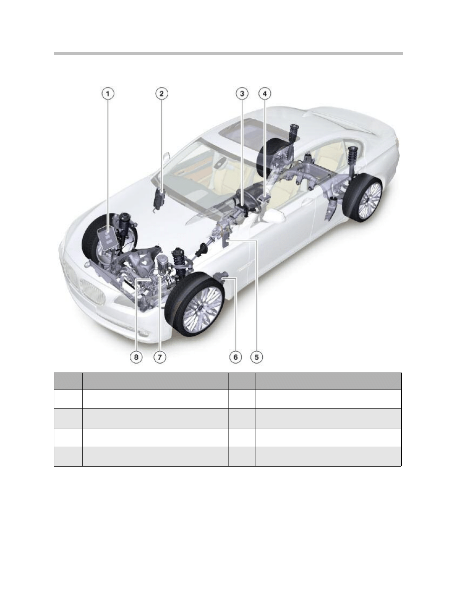
Components of Servotronic Steering (standard)
8
F01 Lateral Dynamics Systems
Index
Explanation
Index
Explanation
1
DME
5
ZGM
2
Front power distribution box
6
DSC
3
SZL
7
Servotronic valve
4
ICM
8
Electronic volumetric flow control (EVV) valve
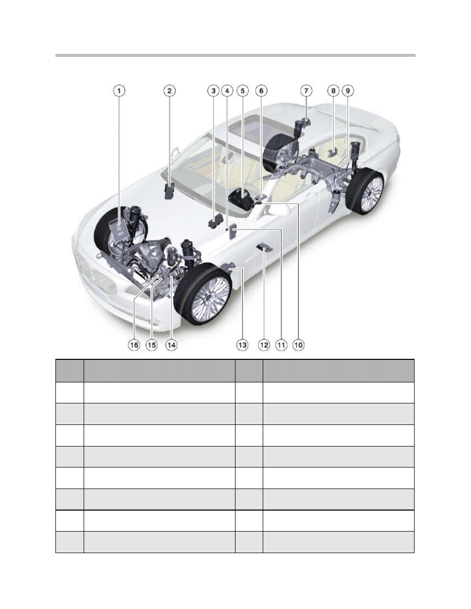
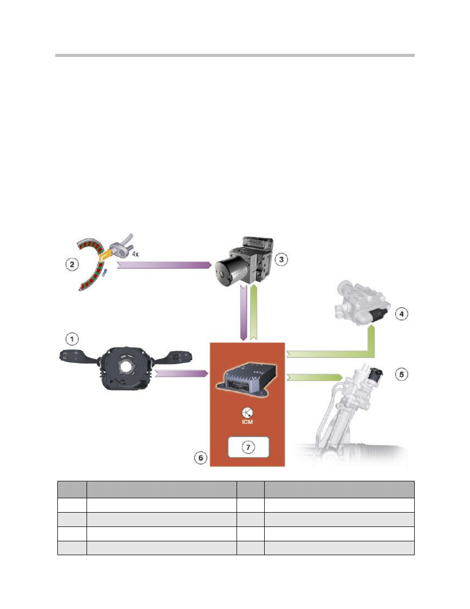
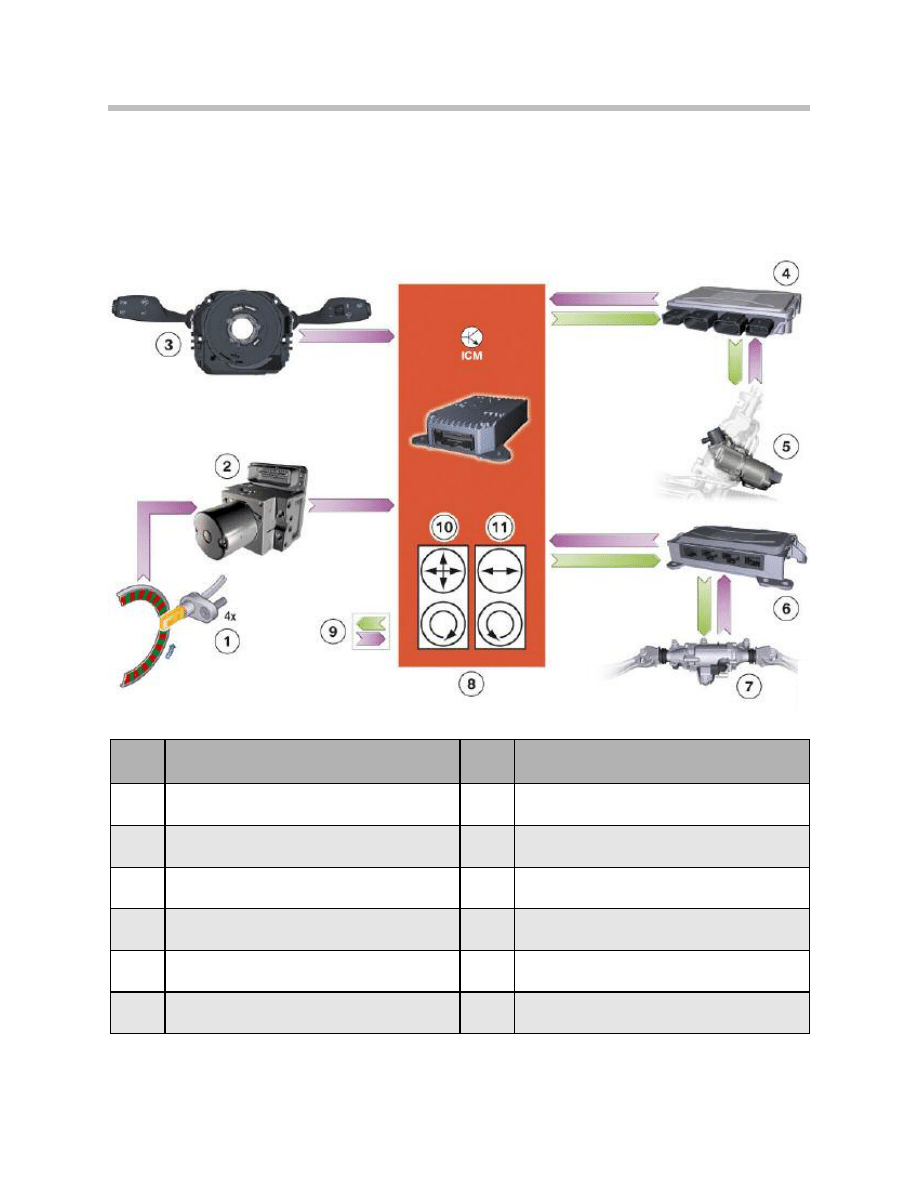
Components of Integrated Active Steering
9
F01 Lateral Dynamics Systems
Index
Explanation
Index
Explanation
1
DME
9
Rear-wheel steering actuator (HSR)
2
Front power distribution box
10
SZL
3
CAS
11
ZGM
4
Brake light switch
12
Active Steering actuator control unit
5
Instrument cluster
13
DSC
6
Integrated Chassis Management (ICM)
14
Active Steering actuator motor with motor
angular position sensor and lock
7
Rear power distribution box
15
Electronic volumetric flow control (EVV) valve
8
HSR control unit
16
Servotronic valve
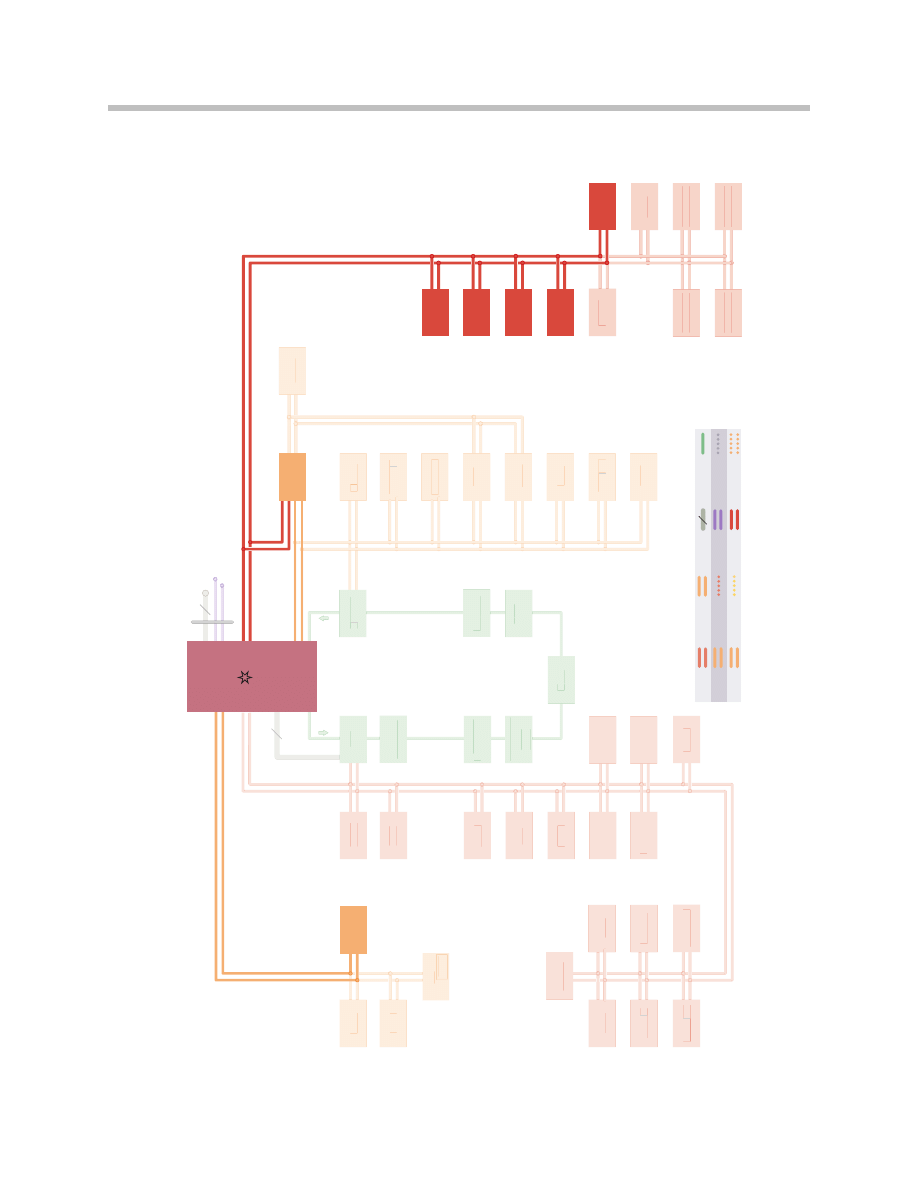
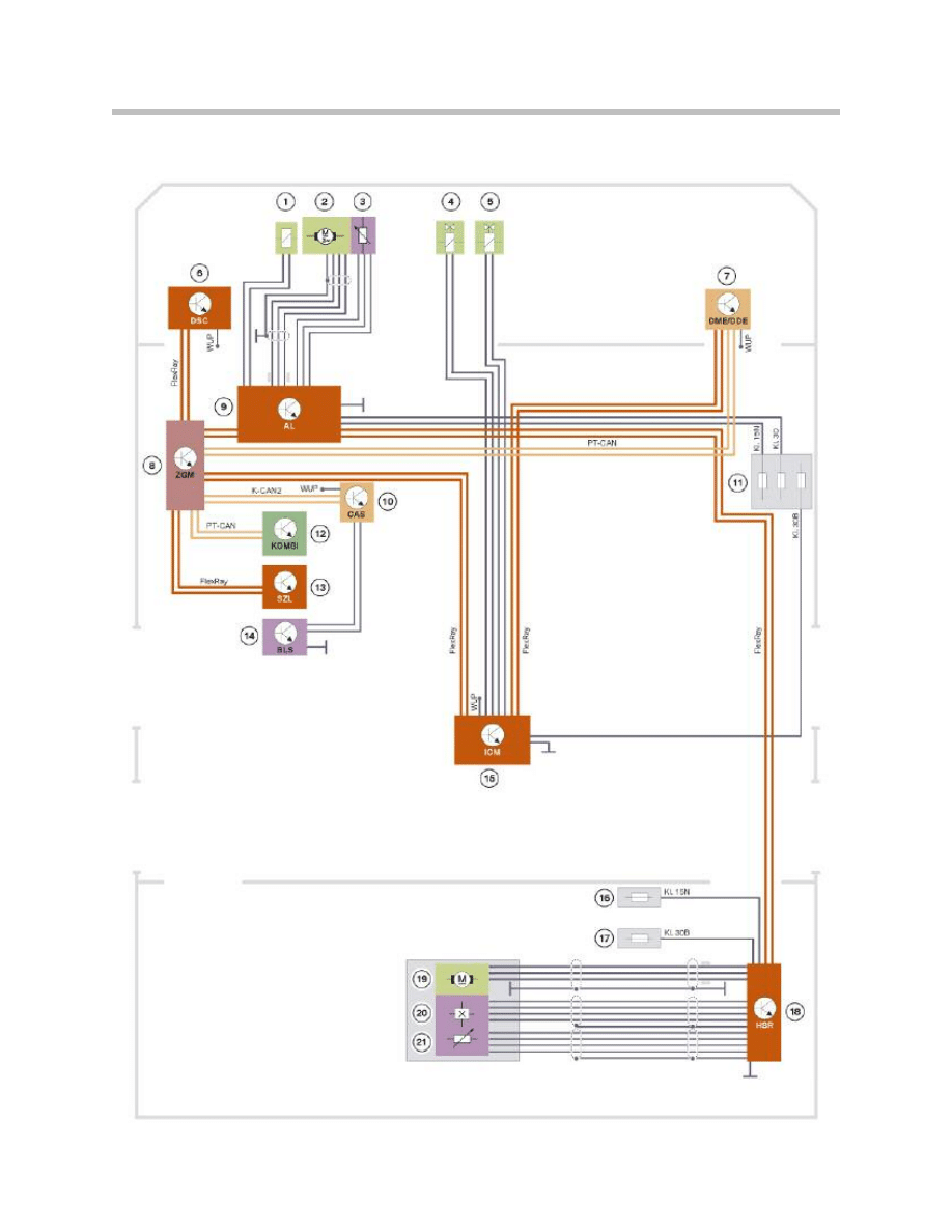
Bus Diagram for Lateral Dynamics Systems
10
F01 Lateral Dynamics Systems
5
PT-C
AN2
5
FRM
FZD
IHK
A
SM
BFH
SM
FAH
SM
FA
SM
BF
FKA
HUD
CID
FD
FD2
TRS
V
C
HiF
i
VSW
CON
ULF
-SBX
Hig
h
SD
ARS
T
CU
T
OP
HiF
i
D
VD
EMA
FA
EMA
BF
NVE
KAF
AS
GWS
EKP
S
EGS
CIC
JB
PDC
K
OMB
I
A
CSM
OBD
SWW
TPMS
K-C
AN
EMF
EDC
SVR
EDC
SHR
EDC
SVL
EDC
SHL
VDM
RSE
Mid
HKL
EHC
5
PT-C
AN2
5
FRM
FZD
IHK
A
SM
BFH
SM
FAHFF
SM
FAFF
SM
BF
FKA
HUD
CID
FD
FD2
TRS
V
C
HiF
i
VSW
CON
ULF
-SBX
Hig
h
SD
ARS
T
CU
T
OP
HiF
i
D
VD
EMA
FAFF
EMA
BF
NVE
KAF
ASFF
GWS
EKP
S
EGS
CIC
JB
PDC
K
OMB
I
KK
A
CSM
OBD
SWW
TPMS
K-C
AN
EMF
EDC
SVR
EDC
SHR
EDC
SVL
EDC
SHL
VDM
RSE
Mid
HKL
EHC
MOS
T
Ethern
et
PT
-C
AN
PT
-C
AN2
K-C
AN
Fle
xR
ay
Loc
al-C
AN
D-C
AN
K-B
us
(pr
ot
ok
oll)
BSD
LIN
-B
us
5
K-C
AN2
HSR
ICM
AL
DSC
Fle
xR
ay
SZL
K-C
AN2
C
AS
ZGM
DME
PT
-C
AN

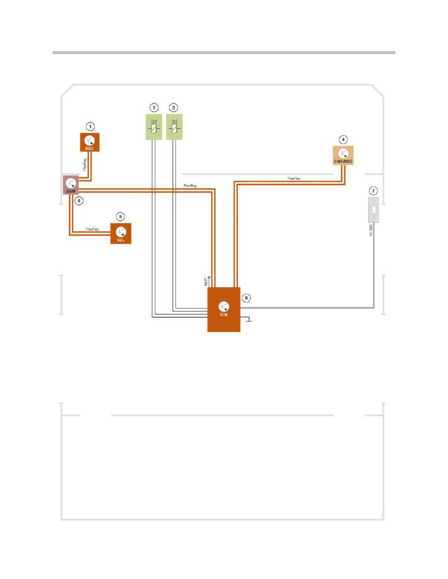
11
F01 Lateral Dynamics Systems
Index
Explanation
Index
Explanation
CAS
Car Access System
SZL
Steering column switch cluster
ZGM
Central Gateway Module
HSR
Rear-wheel steering control unit
DME
Digital Motor Electronics
AL
Active Steering
DSC
Dynamic stability control
ICM
Integrated Chassis Management
System Circuit Diagram for Servotronic System
12
F01 Lateral Dynamics Systems

13
F01 Lateral Dynamics Systems
Index
Explanation
Index
Explanation
1
Dynamic stability control
5
Central Gateway Module
2
Electronic volumetric flow control (EVV) valve
6
Steering column switch cluster
3
Servotronic valve
7
Front power distribution box
4
Digital Motor Electronics
8
Integrated Chassis Management
14
F01 Lateral Dynamics Systems
System Circuit Diagram for Integrated Active Steering

15
F01 Lateral Dynamics Systems
Index
Explanation
Index
Explanation
1
Active Steering lock
12
Instrument cluster
2
Active Steering electric motor
13
Steering column switch cluster
3
Active Steering motor angular position sensor
14
Brake light switch
4
Electronic volumetric flow control (EVV) valve
15
Integrated Chassis Management
5
Servotronic valve
16
Right rear power distribution box
6
Dynamic stability control
17
Battery power distribution box
7
Digital Motor Electronics
18
Rear suspension slip angle control
8
Central Gateway Module
19
HSR electric motor
9
Active Steering
20
Hall-effect sensor
10
Car Access System
21
Track-rod position sensor
11
Front power distribution box

Steering Systems
Implementation of the Integrated Active Steering function has essentially been made
possible by the new ICM system complex on the F01/F02.
The Servotronic function including valve control is also taken over by the ICM control
unit. That steering control function is also influenced by the Driving Dynamics Control
function.
Advantages of Integrated Active Steering:
• Extension of Active Steering (AL) by the addition of rear-wheel steering (HSR)
• Variable steering-gear ratio (steering angle amplification factor)
• Independent control of rear-wheel steering angle (steer by wire)
• Servotronic
• Handling stabilization functions
• Reduction of braking distance under split surface braking conditions.
Supply of Signals
Signals from external sensors
The ICM control unit reads the following signals that are essential to the Integrated
Active Steering from external sensors:
• Four wheel-speed signals sent via Flexray by the DSC
• Steering angle sent via Flexray by steering column switch cluster
• Status of AL and HSR actuators transmitted via Flexray.
However, because the rear-wheels are steerable, the steering angle of the front wheels
alone is not definitive for dynamic handling control purposes. Therefore, the ICM control
unit also takes the steering angle of the rear wheels into account. Ultimately, the effec-
tive steering angle is calculated from the two steering angles (front and rear wheels). The
effective steering angle indicates the angle to which the front wheels would have to be
turned to bring about the same vehicle response without steerable rear wheels. That
variable is the easiest for all vehicle systems to use to analyse the steering action.
Control and Modulation of Steering
Both the basic steering system and the optional Integrated Active Steering on the
F01/F02 incorporate the Servotronic function. That speed-sensitive power assistance
function is effected by way of the Servotronic valve on the steering gear.
The Servotronic valve is always controlled by the ICM control unit regardless of the
equipment options fitted. Accordingly, the Servotronic function algorithm is stored on
the ICM control unit.
16
F01 Lateral Dynamics Systems
Functions
Similarly regardless of equipment options, the steering system also always incorporates a
proportional control valve which is controlled by the ICM control unit. With the aid of that
valve, the power steering pump’s volumetric flow rate can be electronically adjusted. For
that reason it is also referred to as the “electronic volumetric flow control” valve
(EVV valve).
That valve too is controlled by the ICM control unit. Depending on the degree of power
assistance demanded at the time, the volumetric flow rate delivered by the power steer-
ing pump is split between the steering valve and a bypass circuit. The ratio of that split
can be infinitely varied. The less power assistance is required, the more hydraulic fluid is
diverted into the bypass circuit. As the hydraulic fluid does not have to do any work in the
bypass circuit, less power is required to drive the power steering pump. Consequently,
the proportional control valve helps to reduce fuel consumption and CO
2
emissions.
17
F01 Lateral Dynamics Systems
Index
Explanation
Index
Explanation
1
Steering column switch cluster
5
Servotronic valve
2
Wheel speed sensor
6
Integrated Chassis Management
3
Dynamic stability control
7
"Steering control" function on ICM
4
Electronic volumetric flow control (EVV) valve
Inputs/outputs: control of steering by ICM
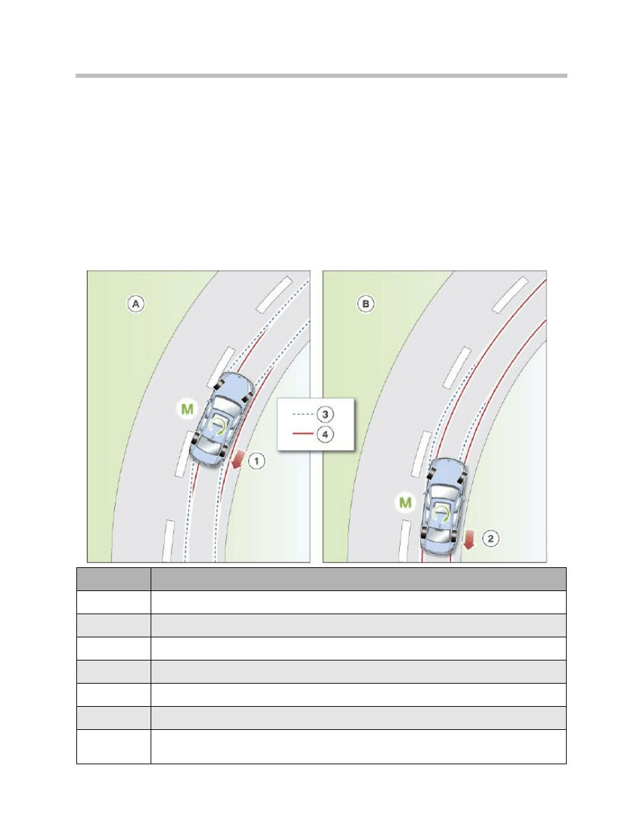
Higher-level Dynamic Handling Control
Centralized Dynamic Handling Control
The interventions by the dynamic handling control systems are performed with the aim of
improving agility and traction. Quite obviously, they also re-stabilize the vehicle when
required. On previous vehicles the various functions were performed by a number of
discrete systems which, although they communicated with one another, nevertheless had
strictly defined limits to their spheres of operation. Accordingly, the interaction of all
systems which ultimately determines the overall handling response, was difficult to har-
monize.
18
F01 Lateral Dynamics Systems
Index
Explanation
A
Correction of unstable handling
B
Early intervention to bring about neutral handling
1
Individual modulation of brakes to correct understeer
2
Individual modulation of brakes to prevent understeer
3
Course of an understeering vehicle
4
Course of a vehicle with neutral handling
M
Yaw force acting on the vehicle as a result
of individual modulation of brakes
Influence on handling characteristics by dynamic handling control system

The Integrated Chassis Management system on the F01/F02 employs centralized
dynamic handling control. It compares the vehicle response desired by the driver with the
actual motion of the vehicle at that moment. By so doing, it is able to determine whether
and in what way intervention in the dynamic handling systems is required.
The output variable of the centralized dynamic handling control system is a yaw force. It
brings about a yawing motion on the part of the vehicle that is superimposed over the
existing movement of the vehicle. In that way, the behavior of the vehicle can be “correct-
ed” if a difference from what is desired by the driver is detected. The classic examples of
that are vehicle understeer or oversteer.
A new feature of the ICM on the F01/F02, however, is that the dynamic handling systems
are brought into action even before such a discrepancy is detected. Thus, the interven-
tions by the dynamic handling systems take place long before the vehicle becomes
unstable. As a result, the vehicle feels much better balanced than would be achievable
with a conventional suspension and steering set-up. The vehicle displays neutral handling
characteristics in many more situations and does not even begin to under or oversteer.
This new function is made possible by very precise computation models and new control
strategies by which the handling characteristics can be assessed and influenced.
19
F01 Lateral Dynamics Systems

Co-ordinated Intervention by the Dynamic Handling Systems
The possibilities for intervention available in the past (and, of course, still available now) in
order to generate the required yaw force calculated by the central dynamic handling
controller are listed below. In brackets in each case are the dynamic handling systems
concerned.
• Modulation of individual brakes (DSC)
• Adjustment of engine torque (ASC+T, DSC, MSR)
• Adjustment of front-wheel steering angle independently of driver input
(Active Steering).
Subordinate to the centralized dynamic handling control system is an “actuator coordina-
tion” function. It decides which dynamic handling system can be used to produce the
yaw force in the particular situation concerned.
For example, if the vehicle is exhibiting significant understeer, it can be counteracted by
controlled braking of the rear wheel on the inside of the bend. If the vehicle has
Integrated Active Steering, the same effect can be brought about even more harmo-
niously by steering the rear wheels to an appropriate degree.
As both means of intervention are limited in their degree, it can also be useful to use
them both simultaneously. Avoidance of understeer is noticeable to the driver in the
shape of a significant gain in agility.
The F01/F02 is also the first model on which there is true functional networking between
the Integrated Chassis Management and vertical dynamics management functions. But
that doesn’t simply mean that the ICM registers the ride height data, processes it and
passes to the VDM.
An integral component of the dynamic handling control system is that the ICM also
actively initiates the Dynamic Drive function in order to affect the self-steering character-
istics. As is familiar from conventional suspension and steering designs, a stiffer anti-roll
bar results in a lower achievable overall lateral friction force at the pair of wheels con-
cerned. The actuator motors in the Dynamic Drive anti-roll bars can be used to simulate
the effect of stiffer and more flexible anti-roll bars.
Thus the ICM centralized dynamic handling control system can use the Dynamic Drive’s
active anti-roll bars to selectively control the available lateral friction force at a pair of
wheels. If the vehicle is oversteering, that means there is too little lateral friction force on
the rear wheels. In that case, it is better to reduce the roll limiting force on the rear sus-
pension. In return, there is a gain in lateral friction force on the rear wheels which helps to
stabilize the vehicle.
The input/output diagram on the following page summarizes the effect of the centralized
dynamic handling control functions on the ICM control unit.
20
F01 Lateral Dynamics Systems
21
F01 Lateral Dynamics Systems
Index
Explanation
Index
Explanation
1
Input signals from external sensors
8
VDM control unit
2
Integrated Chassis Management (ICM)
9
Active stabilizer bar
3
Dynamic stability control
10
"Actuator co-ordination" function on ICM
4
Active Steering control unit
11
"Centralized dynamic handling control" function
5
AS actuating unit
12
"Sensor signal processing" function
6
HSR control unit
13
Integrated DSC sensor (combined linear acceler-
ation, lateral acceleration and yaw rate sensor)
7
HSR actuator unit
14
Integrated DSC sensor (additional combined
lateral acceleration and yaw rate sensor)
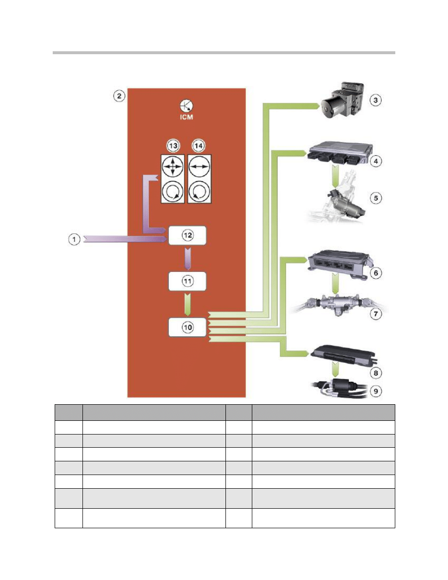
Centralized dynamic handling control on ICM
Distributed Functions: ICM and Actuator Control Units
The distribution of functions between the ICM and the other dynamic handling control
units in the case of Integrated Active Steering is described below.
22
F01 Lateral Dynamics Systems
Index
Explanation
Index
Explanation
1
Wheel speed sensors
7
HSR actuator unit
2
Dynamic stability control
8
Integrated Chassis Management (ICM)
3
Steering column switch cluster with steering-
angle sensor
9
Other input and output signals*
4
Active Steering control unit
10
Integrated DSC sensor (combined linear acceler-
ation, lateral acceleration and yaw rate sensor)
5
AS actuating unit
11
Integrated DSC sensor (additional combined lat-
eral acceleration and yaw rate sensor)
6
HSR control unit
ICM and actuator control units AL and HSR
* Instrument cluster failure BLS-CAS braking DME engine torque increase.

The Integrated Chassis Management is the control unit which computes the higher-level
dynamic handling control functions for the Integrated Active Steering.
From the current vehicle handling status and the desired course indicated by the driver,
the Integrated Chassis Management calculates individual settings for the variable steer-
ing-gear ratio and the superimposed yaw rate. Once they have been prioritized, the ICM
provides a required setting in each case for the AL and HSR control units. The setting
specified is a required steering angle to be applied to the front and rear wheels respec-
tively.
The AL control unit receives the required setting and has the main job of controlling the
actuators so as to correctly apply the specified setting. Thus the AL Active Steering
control unit is purely an actuator control unit. The same applies to the HSR control unit.
It too is an actuator control unit. Like the AL control unit, it is responsible only for imple-
menting the required steering angle specified by the ICM.
With the introduction of the ICM on the E71, this type of function distribution was used
for the first time. On the F01/F02, it has been expanded to the extent that
• the ICM now controls all linear and lateral dynamics systems (AL, HSR and also
DSC) and
• the ICM is the master control unit both for linear dynamics and unstable handling
situations.
The interface between the Integrated Chassis Management and the Dynamic Stability
Control (DSC) represents a special case.
23
F01 Lateral Dynamics Systems
Functional Areas of Integrated Active Steering
Low Speed Range
The variable steering-gear ratio of the Active Steering component reduces steering effort
to approximately 2 turns of the steering wheel from lock to lock. In the low speed range
up to approximately 37 mph, the variable steering-gear ratio for the front wheels is
combined with a degree of opposite rear-wheel steer. The effect is to increase vehicle
agility.
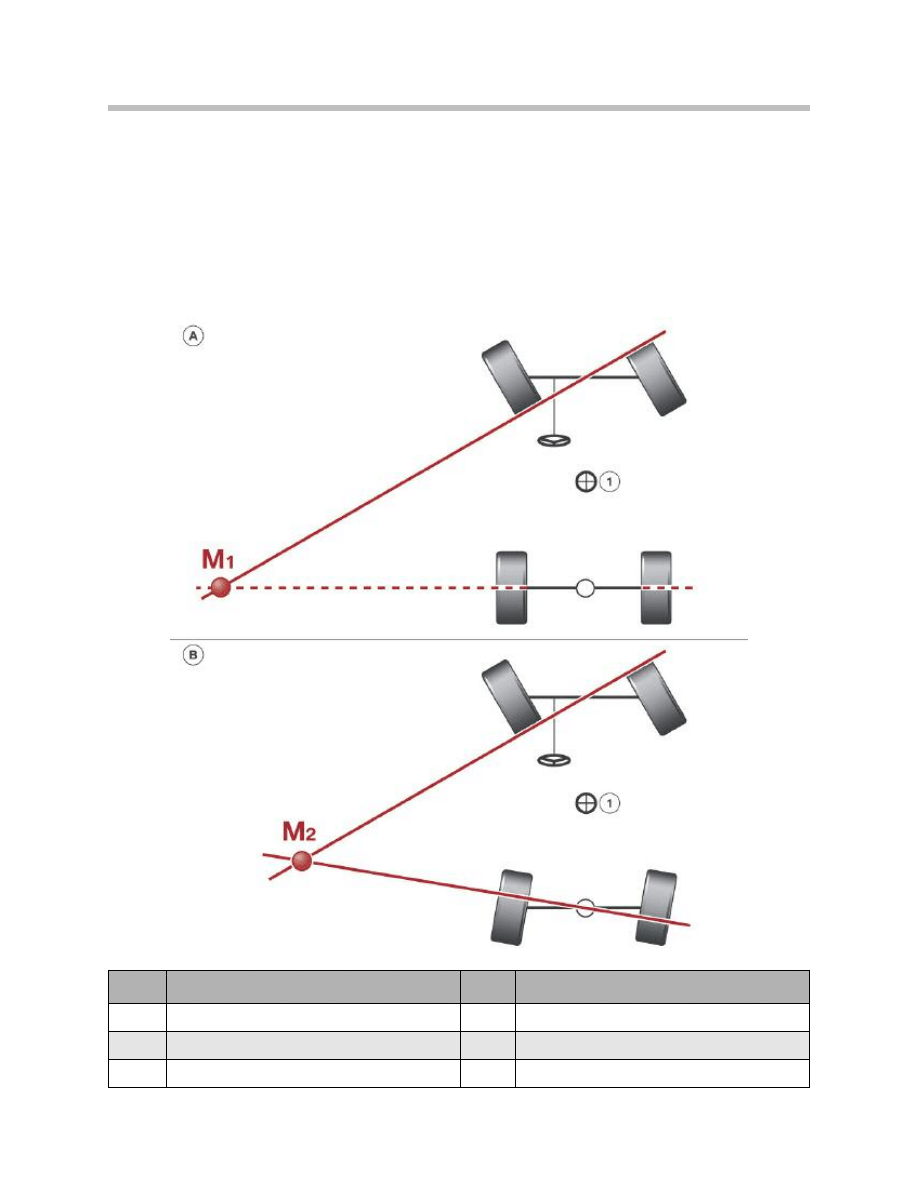
24
F01 Lateral Dynamics Systems
Index
Explanation
Index
Explanation
A
Conventional steering system
M2
Momentary axis 2
B
Integrated Active Steering
1
Center of vehicle
M1
Momentary axis 1
When the steering wheels of a vehicle are turned, it follows a curved path around what is
called the momentary axis “M”.
In the case of conventional vehicles, that momentary axis is positioned at a point along
the extension of a line passing through the center of the rear wheels.
Active Steering intervention turns the rear wheels in the opposite direction at speeds up
approximately 37 mph.
The consequence of the rear-wheel steering intervention is that the axis of rotation
moves closer to the center of the vehicle with the same amount of steering effort.
In terms of agility and dynamic handling, that is equivalent to a vehicle with a shorter
wheelbase.
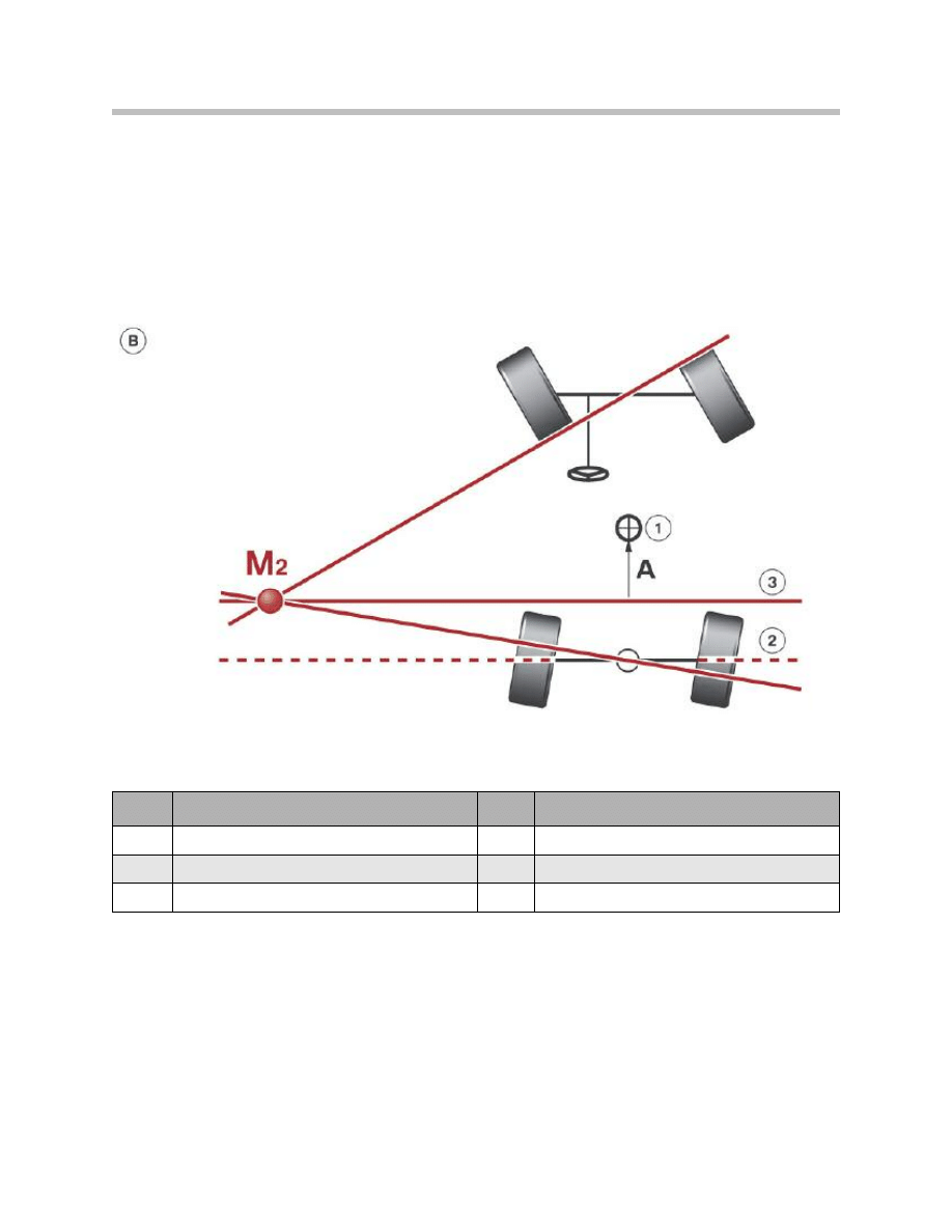
25
F01 Lateral Dynamics Systems
Index
Explanation
Index
Explanation
A
Effective wheelbase reduction
1
Center of vehicle
B
Integrated Active Steering
2
Straight line through Center of rear wheels
M2
Momentary axis 2
3
Axis of rotation closer to center of vehicle
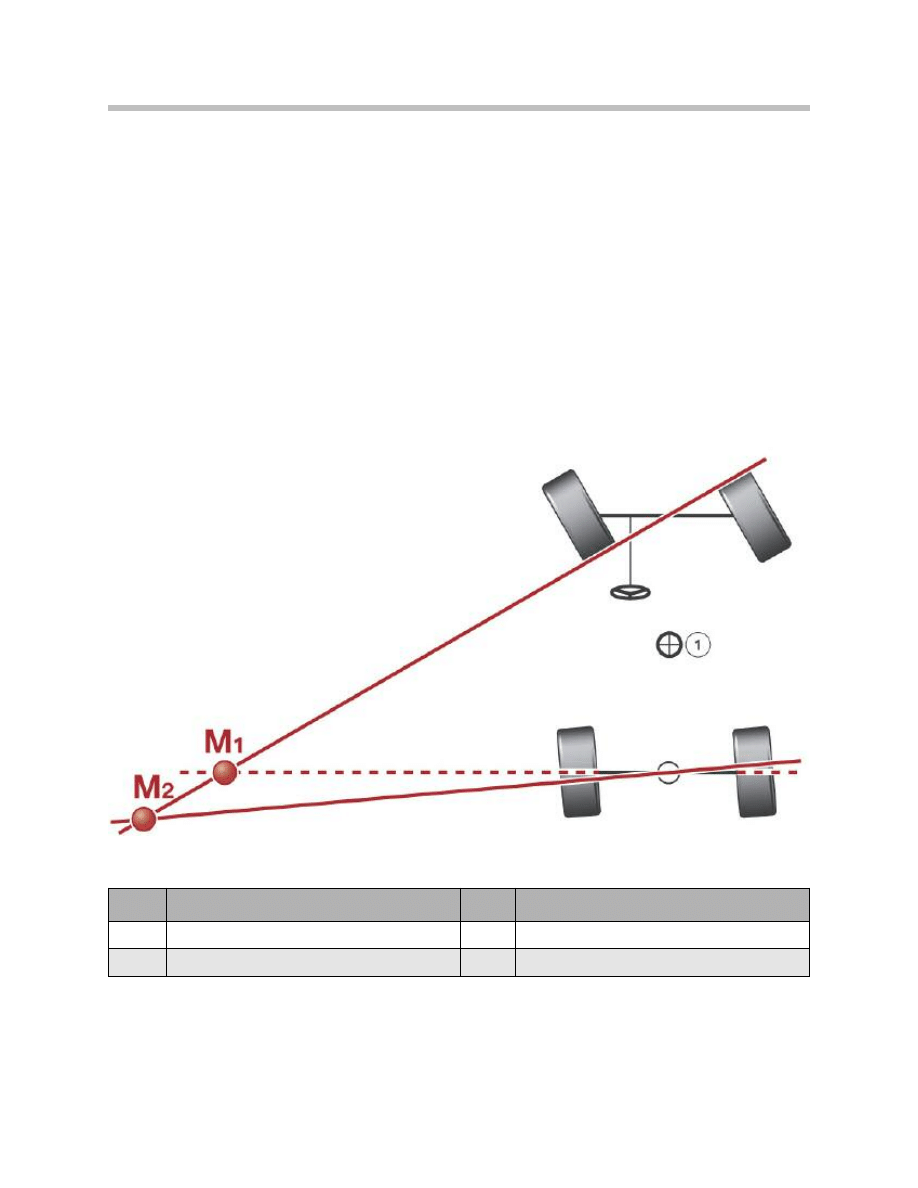
High Speed Range
As the vehicle speed increases, the degree of steering angle amplification by the Active
Steering component is reduced. The steering-gear ratio becomes less direct.
At the same time, the steering strategy adopted by the Integrated Active Steering
changes. Whereas, at low speeds, the rear wheels are steered in the opposite direction to
the front wheels, at higher speeds the rear wheels are steered in the same direction as
the front.
The momentary axis moves further back, equivalent to a vehicle with a longer wheelbase,
producing more stable straight-line handling. The radius of the curve becomes longer.
By the combination with the Active Steering, an additional amount is added to the steer-
ing angle of the front wheels so that the radius of the curve and the required amount of
steering lock remain at the familiar level.
26
F01 Lateral Dynamics Systems
Index
Explanation
Index
Explanation
M1
Momentary axis 1
1
Center of vehicle
M2
Momentary axis 2
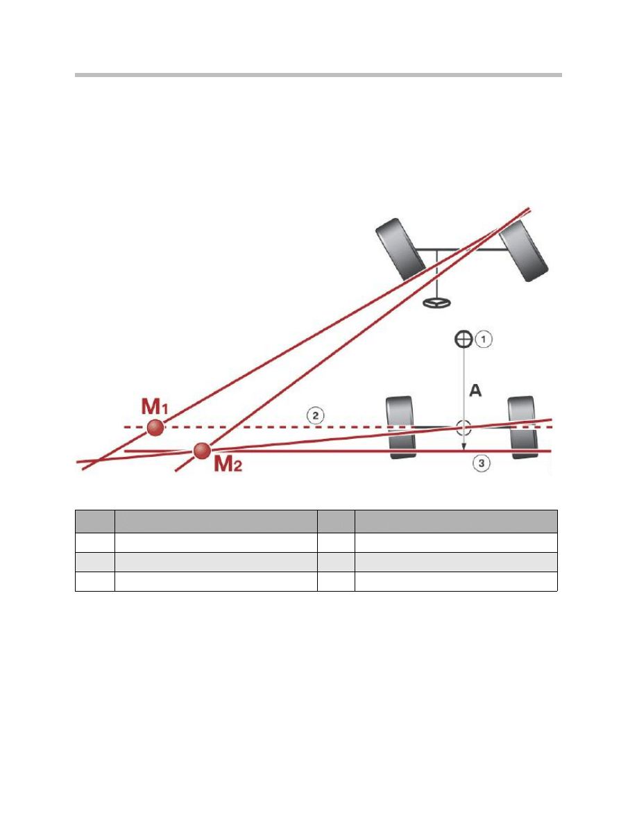
All in all, co-ordination of the steering interventions at front and rear makes lane changes
and steering maneuvers considerably easier to negotiate without sacrificing agility or bal-
ance.
Combination of the Active Steering with the new rear-wheel steering system offers bene-
fits for the driver at all speeds.
27
F01 Lateral Dynamics Systems
Index
Explanation
Index
Explanation
M1
Momentary axis 1
1
Center of vehicle
M2
Momentary axis 2
2
Straight line through center of rear wheels
A
Effective wheelbase increase
3
Axis of rotation further from center of vehicle
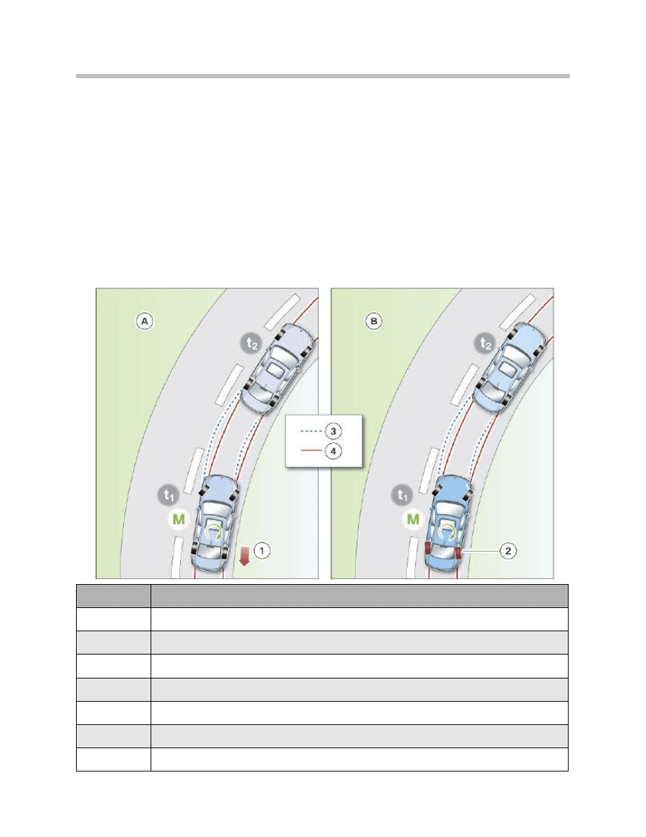
Handling Stabilization by Integrated Active Steering When Understeering
When changing lanes quickly, all vehicles have a tendency to produce a significant yaw
response and can sometimes start to oversteer.
If the ICM dynamic handling controller detects a difference between the response
desired by the driver and the reaction of the vehicle, it initiates co-ordinated steering
interventions on the front and rear wheels. The speed of the stabilizing intervention is
such that it is hardly discernible by the driver.
Braking interventions by the DSC, which have a decelerating effect, can be largely dis-
pensed with.
The end result is that the vehicle is more stable and more effectively damped.
28
F01 Lateral Dynamics Systems
Index
Explanation
A
Prevention of understeer by individual brake modulation (DSC)
B
Prevention of understeer by rear-wheel steering intervention (IAL)
1
Individual brake modulation (DSC)
2
Rear-wheel steering intervention (IAL)
3
Course of an understeering vehicle
4
Course of a vehicle with neutral handling
M
Yaw force acting on the vehicle as a result of dynamic handling system intervention
Possible dynamic handling interventions when understeering

If the driver underestimates how sharp a bend is when driving quickly on a country road,
he/ she can be caught out by sudden understeer.
By virtue of its inherent features, Active Steering was only able to react to vehicle over-
steer.
Integrated Active Steering incorporating active rear-wheel steering is now also able to
make corrective interventions when the vehicle is oversteering and thus further increases
active safety.
29
F01 Lateral Dynamics Systems
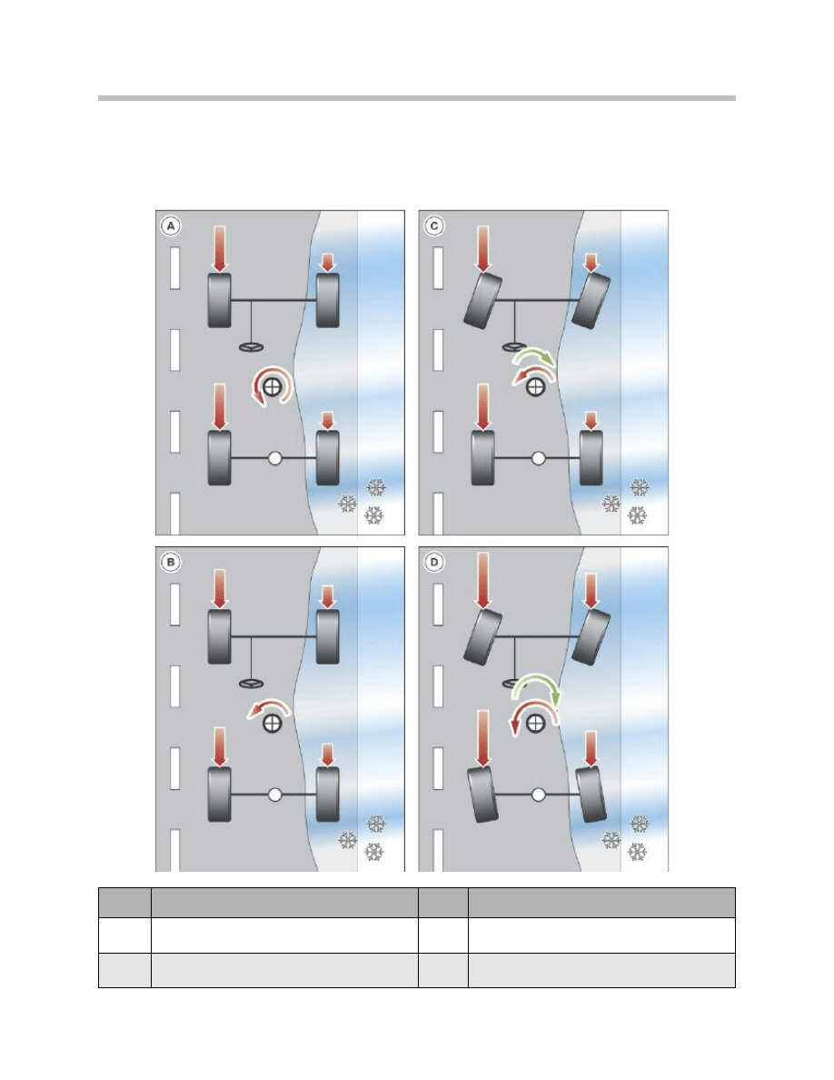
Handling Stabilization by Integrated Active Steering Under Split Surface
Braking Conditions
Hard braking on road surfaces which provide less grip for the wheels on one side of the
vehicle than on the other causes the vehicle to yaw towards the side with more grip.
30
F01 Lateral Dynamics Systems
Index
Explanation
Index
Explanation
A
Vehicle without DSC
C
Vehicle with DSC and AL
(yaw force compensation on E90)
B
Vehicle with DSC
D
Vehicle with DSC and Integrated Active Steering

Under emergency braking, the driver of a conventional vehicle then has to correct the
vehicle’s course.
Under such split surface braking conditions, the dynamic handling controller generates a
stabilizing yaw force by opposite steering interventions on the front and rear wheels.
A) Without DSC
In the case of a vehicle without DSC, maximum braking effect is achieved by the wheels
on the dry side of the road, while those on the wet or icy side produce very little retarda-
tion.
As a result, a very substantial yaw force acting in an counterclockwise direction is pro-
duced, causing the vehicle to swerve to the right.
B) With DSC
A vehicle equipped with DSC brakes the individual wheels more sensitively in order to
keep the yaw force within manageable limits for the driver, which however, slightly
increases the braking distance.
C) With DSC and AL
The additional “yaw force compensation” function represents a significant safety feature.
When braking on road surfaces with differences in frictional coefficient between one side
of the vehicle and the other (tarmac, ice or snow), a turning force is generated around the
vehicle’s vertical axis (yaw force) rendering the vehicle unstable. In such cases, the DSC
calculates the required steering angle for the front wheels and the Active Steering imple-
ments it by actively applying opposite lock.
As a result, an opposing yaw force around the vertical axis is generated, “compensating”
for the original yaw force (cancelling it out, i.e. the vehicle is stabilized by intelligent co-
ordination of DSC brake modulation and AL steering, constituting a safety feature unique
in this class of vehicle).
D) With DSC, dynamic handling controller and Integrated Active Steering
Under such split surface braking conditions, the dynamic handling controller generates a
stabilizing yaw force by opposite steering interventions on the front and rear wheels.
That counteracts the slewing of the vehicle caused by the uneven braking forces.
At the same time, maximum braking force can be applied in order to achieve a short brak-
ing distance.
Integrated Active Steering is a logical development from the Active Steering systems.
The functions of the systems complement each other perfectly, taking the driving experi-
ence to a new dimension.
31
F01 Lateral Dynamics Systems
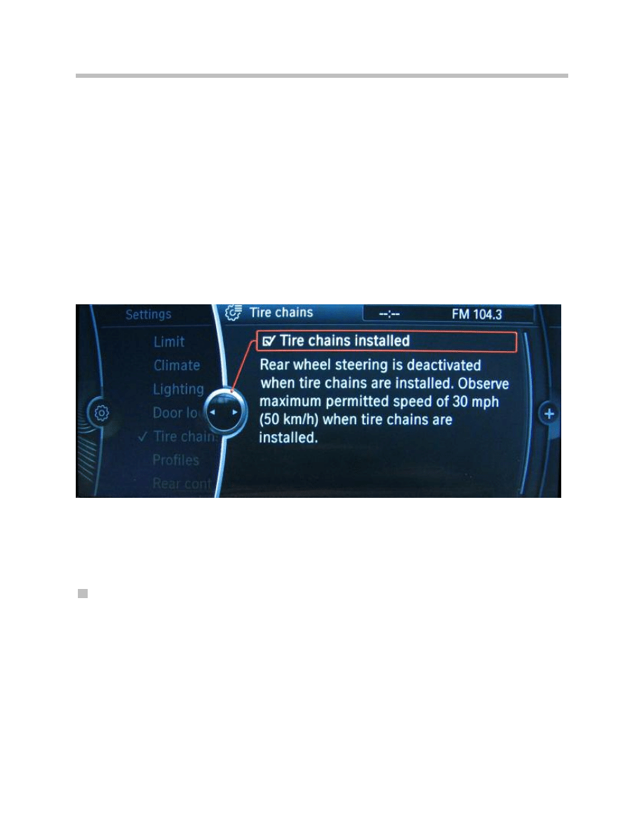
Integrated Active Steering Special Function
Quite obviously, Active Steering systems must not be capable of being switched on or off
by the driver.
In the case of Integrated Active Steering, there is a special feature in that regard because
if snow chains are fitted to the rear wheels, Active Steering of the rear wheels must be
disabled.
When snow chains are fitted, the rear-wheel steering is deactivated in order to ensure
that the wheels are always free to rotate.
Automatic snow-chain detection assists the driver and indicates the detected status on
the Control Display. This does not remove the responsibility for manually changing the
setting.
When show chains are used, the setting on the iDrive Settings menu must be changed
to “Show chains fitted”.
If the maximum speed of 50 kph (31mph) for driving with snow chains is exceeded, the
rear-wheel steering is reactivated regardless of the “Snow chains fitted” setting.
Automatic snow chain detection
It is possible to detect from the wheel-speed sensor signals a characteristic pattern pro-
duced by the motion of the wheel when show chains are fitted (only with BMW-approved
show chains). From that characteristics signal pattern, the control unit is able to detect
whether show chains are fitted on each individual wheel.
32
F01 Lateral Dynamics Systems
Control display message
Steering Systems
There are two lateral dynamics systems available on the F01/F02:
• Servotronic
• Integrated Active Steering
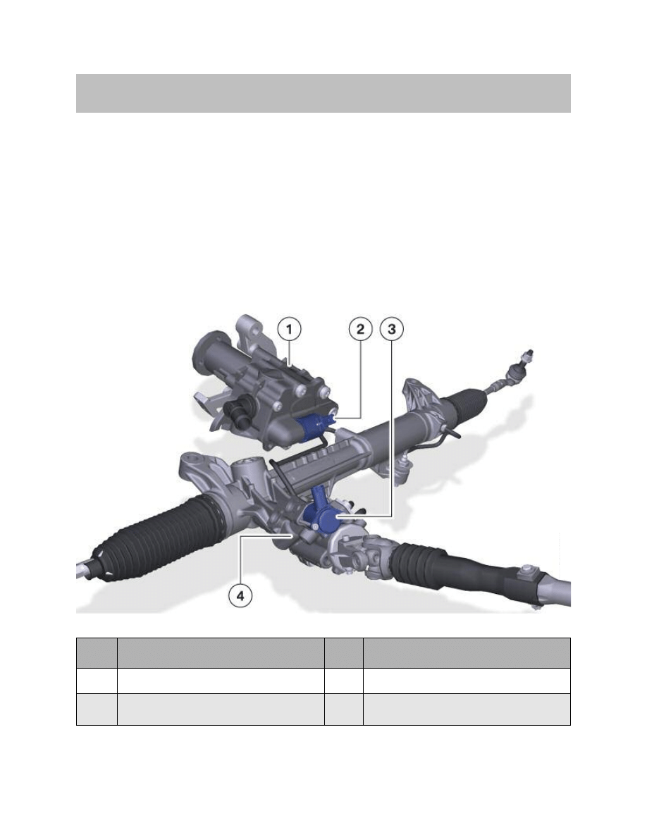
Servotronic Components
The proportional valve for electronic volumetric flow control (EVV valve) and the
Servotronic valve are directly controlled by the ICM regardless of whether the Servotronic
or Integrated Active Steering is fitted.
33
F01 Lateral Dynamics Systems
System Components
Index
Explanation
Index
Explanation
1
Hydraulic pump
3
Servotronic valve
2
Electronic volumetric flow control valve
(EVV valve)
4
Hydraulic power steering control valve body
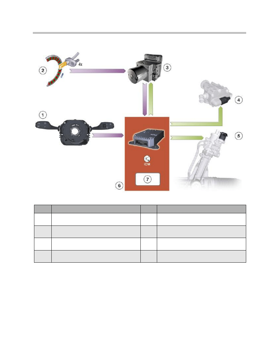
Inputs/outputs: control of steering by ICM
34
F01 Lateral Dynamics Systems
Index
Explanation
Index
Explanation
1
Steering column switch cluster (SZL)
5
Servotronic valve
2
Wheel speed sensor
6
Integrated Chassis Management (ICM)
3
Dynamic stability control (DSC)
7
"Steering control" function
4
Electronic volumetric flow control (EVV) valve
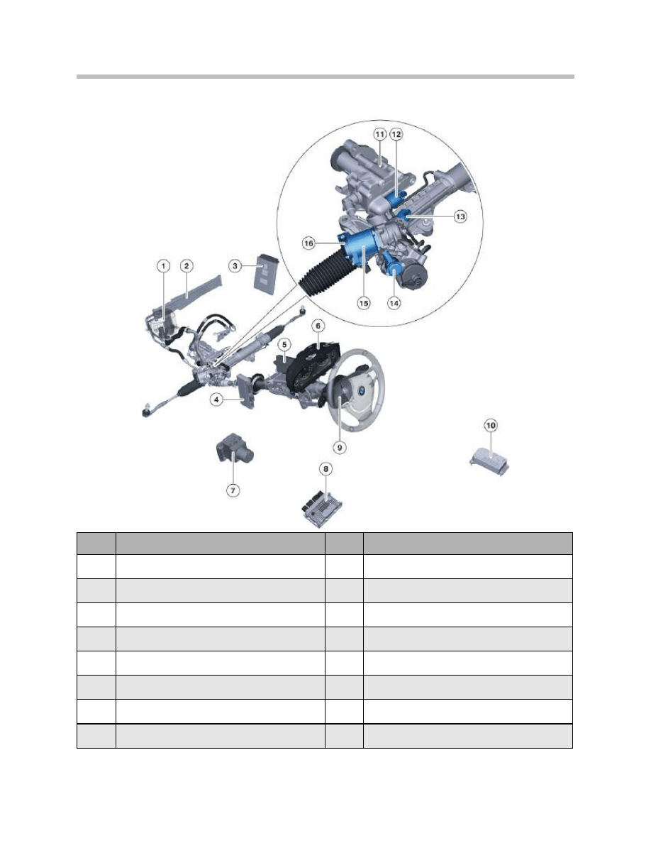
Components of Integrated Active Steering
35
F01 Lateral Dynamics Systems
Index
Explanation
Index
Explanation
1
Hydraulic fluid reservoir
9
SZL
2
Power steering cooler
10
ICM
3
DME
11
Hydraulic pump
4
ZGM
12
Electronic volumetric flow control (EVV) valve
5
CAS
13
Lock
6
Instrument cluster
14
Servotronic valve
7
DSC
15
Actuator unit electric motor
8
AL
16
Motor angular position sensor
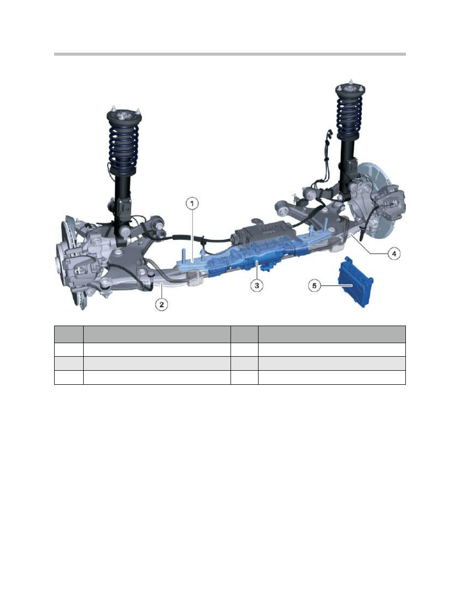
Location of HSR actuator on rear suspension
The special actuator on the rear suspension is fixed underneath a mounting plate on the
rear suspension subframe.
The electromechanical actuator is positioned between the two new track rods of the
Integral V rear suspension. The rear-wheel steering system has its own actuator control
unit which is responsible for controlling and monitoring the actuator.
It was previously the state of the art that control systems were largely independent of one
another.
On the F01/F02, the Integrated Chassis Management (ICM) system brings the separate
systems together.
A central ICM control unit in the ICM architecture replaces the previous dynamic handling
sensors and forms a central dynamic handling controller.
36
F01 Lateral Dynamics Systems
Index
Explanation
Index
Explanation
1
Mounting plate
4
Right track rod
2
Left track rod
5
HSR control unit
3
HSR actuator
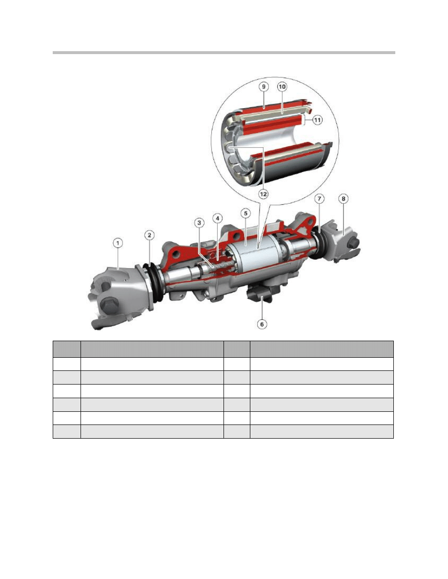
HSR actuator
The electromechanical actuator essentially consists of an electric motor which moves the
two track rods by means of a worm-and-nut steering gear.
The actuator is designed for a maximum travel of ±8 mm, which brings about a maximum
steering angle of ±3 ° at the roadwheel.
The worm-and-nut rear-wheel steering gear is self-inhibiting. That means that if the sys-
tem fails, the vehicle adopts exactly the same handling characteristics as a vehicle without
rear-wheel steering.
37
F01 Lateral Dynamics Systems
Index
Explanation
Index
Explanation
1
Left track rod joint
7
Right shaft gaiter
2
Left shaft gaiter
8
Right track rod joint
3
Worm shaft
9
Iron jacket
4
Worm nut
10
Winding stator
5
Electric motor
11
Permanent magnet
6
Electrical connector
12
Carrier/armature winding iron core
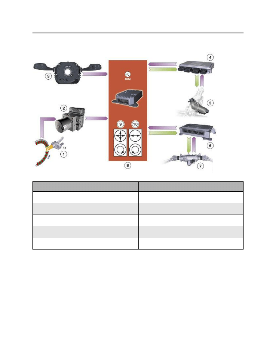
Components and system complex for Integrated Active Steering
38
F01 Lateral Dynamics Systems
Index
Explanation
Index
Explanation
1
Wheel speed sensors
6
HSR control unit
2
DSC
7
HSR actuator unit
3
SZL with steering-angle sensor
8
ICM
4
Active Steering control unit
9
DSC sensor in ICM (linear acceleration,
lateral acceleration and yaw rate sensor)
5
AS actuating unit
10
Back-up DSC sensor in ICM
(lateral acceleration and yaw rate sensor)
Document Outline
- Main Menu
- 01_F01 Introduction
- 02_F01 Powertrain
- 03_F01 Voltage Supply & Bus Systems
- 03.1_F01 Bus Systems
- 03.2_F01 Voltage Supply
- 03.3_F01 Energy Management
- 03.4_F01 Car Access System 4
- 04_F01 Chassis Dynamics
- 04.1_F01 Chassis and Suspension
- 04.2_F01 Dynamic Driving Systems
- 04.3_F01 Longitudinal Dynamics Systems
- 04.4_F01 Lateral Dynamics Systems
- 04.5_F01 Vertical Dynamics Systems
- 04.6_F01 Cruise Control Systems
- 05_F01 General Vehicle Electronics
- 05.1_F01 Comfort Access
- 05.2_F01 Central Locking System
- 05.3_F01 Automatic Soft Close
- 05.4_F01 Power Windows
- 05.5_F01 Sliding Tilting Sunroof
- 05.6_F01 Anti-theft System
- 05.7_F01 Automatic Luggage Compartment Lid
- 05.8_F01 Exterior Lighting
- 05.9_F01 Interior Lighting
- 05.10_F01 Wiper-Washer System
- 05.11_F01 Exterior Rear View Mirrors
- 05.12_F01 Seats
- 05.13_F01 Steering Column Switch Cluster
- 06_F01 Driver Information Systems
- 06.1_F01 Displays Indicators and Controls
- 06.2_F01 Head-up Display
- 06.3_F01 BMW Night Vision 2
- 06.4_F01 Active Blind Spot Detection System
- 06.5_F01 KAFAS
- 06.6_F01 PDC-TRSVC
- 07_F01 Information and Communication Technology
- 07.1_F01 Rear Seat Entertainment Systems
- 07.2_F01 Telephone System
- 07.3_F01 Voice Activation System
- 07.4_F01 Audio Systems
- 08_F01 Climate Control
- 09_F01 Passive Safety Systems
- 10_F01 Service Information
- 10.1_F01 System Functions
- 10.2_ISTA-Programming
Wyszukiwarka
Podobne podstrony:
04 3 F01 Longitudinal Dynamics Systems
04b E70 Lateral Dynamics Systems
04 6 F01 Cruise Control Systems
04 Liczby ujemne i ułamki w systemie binarnym
04 Płazińce, I rok, I semestr, Systematyka zwierząt, wykłady
Wykład 1 04.02, Studia, Współczesne systemy polityczne
PBO G 04 F01 QSMS document distribution list
04 Linux SYSLOG i logi systemowe
04 Struktury spoleczne. Dynamika struktur, studia, wprowadzenie do socjologii
Systemy polityczne 19.04.10, studia UMK, Systemy ekonomiczne w Europie (W.Kosiedowski)
uproszczone ogloszenie o zamowieniu objetym dynamicznym system zakupow, ZAMÓWIENIA PUBLICZNE 3
bezpieczeństwo jako przedmiot badań, 04 - Bezpieczeństwo Narodowe, Mobilizacja w Systemie Obronnym P
Ekologiczne Systemy Chowu i Żywienia Zwierząt - Wykład 04, WYKŁAD IV- EKOLOGICZNE SYSTEMY CHOWU I ZY
Kontrola w zakresie dynamicznym systemu podwieszenia mostu nad rzeką Suir w Irlandii
04 Liczby ujemne i ułamki w systemie binarnym
04 Płazińce, I rok, I semestr, Systematyka zwierząt, wykłady
Wykład 1 04.02, Studia, Współczesne systemy polityczne
Gorban A N singularities of transition processes in dynamical systems qualitative theory of critica
Natiello M , Solari H The user#s approach to topological methods in 3 D dynamical systems (WS, 2007)
więcej podobnych podstron