
Initial Print Date: 01/09
Table of Contents
Subject
Page
Components on the Vehicle . . . . . . . . . . . . . . . . . . . . . . . . . . . . . . . . . . . . .6
Bus System Overview for DSC and EMF . . . . . . . . . . . . . . . . . . . . . . .8
Dynamic Stability Control . . . . . . . . . . . . . . . . . . . . . . . . . . . . . . . . . . . .10
DSC and Integrated Chassis Management . . . . . . . . . . . . . . . . . . . . .14
DSC Displays and Controls . . . . . . . . . . . . . . . . . . . . . . . . . . . . . . . . . .17
New DSC symbols . . . . . . . . . . . . . . . . . . . . . . . . . . . . . . . . . . . . . .17
DSC modes . . . . . . . . . . . . . . . . . . . . . . . . . . . . . . . . . . . . . . . . . . . .18
Integration in dynamic handling control . . . . . . . . . . . . . . . . . . . .18
ADB Active Even When DSC is Off . . . . . . . . . . . . . . . . . . . . . . . . . . .20
Brake Modulation for Increasing Agility . . . . . . . . . . . . . . . . . . . . . . . .21
Interface for Adaptive Braking Assistance . . . . . . . . . . . . . . . . . .24
Hydraulic modulator . . . . . . . . . . . . . . . . . . . . . . . . . . . . . . . . . . . . .27
DSC control unit . . . . . . . . . . . . . . . . . . . . . . . . . . . . . . . . . . . . . . . .28
Location and repair . . . . . . . . . . . . . . . . . . . . . . . . . . . . . . . . . . . . . .29
Wheel speed sensors . . . . . . . . . . . . . . . . . . . . . . . . . . . . . . . . . . . .32
Steering-angle sensor in SZL . . . . . . . . . . . . . . . . . . . . . . . . . . . . .34
F01 Longitudinal Dynamics Systems
Revision Date:

Subject
Page
Important Points for Servicing and Repairs . . . . . . . . . . . . . . . . . . . . . . .36
Dynamic Stability Control (DSC) . . . . . . . . . . . . . . . . . . . . . . . . . . . . . .36
Automatic hold function . . . . . . . . . . . . . . . . . . . . . . . . . . . . . . . . . .36
Signals and sensors . . . . . . . . . . . . . . . . . . . . . . . . . . . . . . . . . . . . .38
Overview of EMF Functions . . . . . . . . . . . . . . . . . . . . . . . . . . . . . . . . . . . .40
Parking brake application . . . . . . . . . . . . . . . . . . . . . . . . . . . . . . . . .40
Roll-away monitoring . . . . . . . . . . . . . . . . . . . . . . . . . . . . . . . . . . . .41
Dynamic braking . . . . . . . . . . . . . . . . . . . . . . . . . . . . . . . . . . . . . . . .42
Emergency release . . . . . . . . . . . . . . . . . . . . . . . . . . . . . . . . . . . . . .43
Running-in the Brakes . . . . . . . . . . . . . . . . . . . . . . . . . . . . . . . . . . . . . .45
EMF control unit . . . . . . . . . . . . . . . . . . . . . . . . . . . . . . . . . . . . . . . .47
Force sensor . . . . . . . . . . . . . . . . . . . . . . . . . . . . . . . . . . . . . . . . . . .49
Parking Brake Button . . . . . . . . . . . . . . . . . . . . . . . . . . . . . . . . . . . . . . .52
Emergency release . . . . . . . . . . . . . . . . . . . . . . . . . . . . . . . . . . . . . .53
Electromechanical Parking Brake (EMF) . . . . . . . . . . . . . . . . . . . . . . .56
Emergency release . . . . . . . . . . . . . . . . . . . . . . . . . . . . . . . . . . . . . .57
Installation mode . . . . . . . . . . . . . . . . . . . . . . . . . . . . . . . . . . . . . . . .57
Running-in the brakes . . . . . . . . . . . . . . . . . . . . . . . . . . . . . . . . . . .58
EMF actuating unit . . . . . . . . . . . . . . . . . . . . . . . . . . . . . . . . . . . . . .58
Electromechanical Parking Brake . . . . . . . . . . . . . . . . . . . . . . . . . . . . .60

Subject
Page
BLANK
PAGE

4
F01 Longitudinal Dynamics Systems
Longitudinal Dynamics Systems
Model: F01/F02
Production: From Start of Production
After completion of this module you will be able to:
• Understand the systems related to Longitudinal Dynamics
• Locate and Identify components of the DSC and EMF systems
• Understand the new DSC functions on the F01/F02
• Understand the changes to the EMF system pertaining to the F01/F02

Refinements in Detail
The longitudinal dynamics systems described in this document comprise the following:
• Dynamic stability control (DSC) and
• Electromechanical parking brake (EMF)
Both DSC and EMF are standard equipment on all F01/F02 models. Thus BMW has
consistently continued the standards set by the E65/E66 and the E70/E71. Both sys-
tems are based on the technology used on the E70/ E71.
However, many specific details have had to be changed. Those changes were essential
to ensure that DSC and EMF could be seamlessly integrated in the new dynamic
handling system complex on the F01/F02.
As far as the Dynamic Stability Control was concerned, co-ordination with the central
dynamic handling controller on the Integrated Chassis Management (ICM) master con-
trol unit had to be taken into consideration. And the new “dynamic handling control”
function also affects the way the DSC operates. The thresholds and the nature of the
DSC interventions have to be adapted to suit the setting selected.
Thus the DSC doesn’t simply contain a setting that suits a luxury-class vehicle such as
the F01/F02. Instead, several different settings have been developed which correspond
to the characteristics of the various dynamic handling control settings.
In addition to adaptation to handling characteristics, there are numerous other changes
to the Dynamic Stability Control on the F01/F02 which relate to location, display fea-
tures, fault diagnosis and repair.
Starting from the basis of the system on the E70/E71, the electromechanical parking
brake has been adapted to the requirements of the F01/F02. That includes such things
as location and attachment to the vehicle. In addition, design enhancements have been
introduced to make the EMF actuator quieter in operation.
This reference document sets out in detail all the changes to the Dynamic Stability
Control and electromechanical parking brake that are specific to the F01/F02.
However, features of the two systems that are familiar from the E70/ E71 are not repeat-
ed in this document. Those details can be found in the respective training manuals.
5
F01 Longitudinal Dynamics Systems
Introduction
Components on the Vehicle
6
F01 Longitudinal Dynamics Systems
System Overview
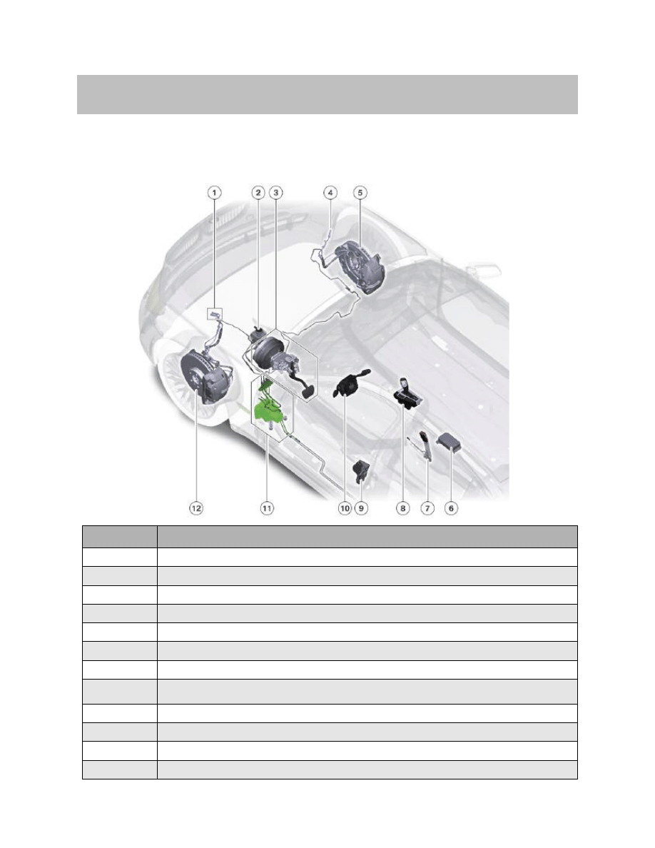
Components of Dynamic Stability Control and electromechanical
parking brake on F01/F02 (front half of vehicle)
Index
Explanation
1
Connection for front left wheel-speed sensor and brake-pad wear sensor
2
Brake fluid reservoir with brake fluid level switch
3
Brake pedal cluster (brake pedal, brake servo unit, tandem master cylinder)
4
Connection for front right wheel-speed sensor
5
Wheel brake, front right
6
Integrated Chassis Management control unit
7
Seat belt buckle contact, driver's seat
8
Center console control panel (DTC button, handling setting switch,
parking brake button, automatic hold button)
9
Door switch, driver's door
10
Steering column switch cluster with steering-angle sensor
11
DSC control unit and hydraulic modulator
12
Wheel brake, front left
7
F01 Longitudinal Dynamics Systems
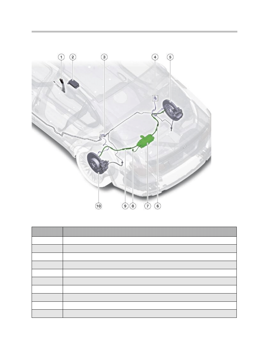
Index
Explanation
1
Seat belt buckle contact, driver's seat
2
Integrated Chassis Management control unit
3
Connection for rear left wheel-speed sensor
4
Connection for rear right wheel-speed sensor and brake-pad wear sensor
5
Wheel brake, rear right
6
Right EMF brake cable
7
Electromechanical parking brake control unit and actuator unit
8
Emergency release EMF
9
Left EMF brake cable
10
Wheel brake, rear left
Components of Dynamic Stability Control and electromechanical parking
brake on F01/F02 (rear half of vehicle)
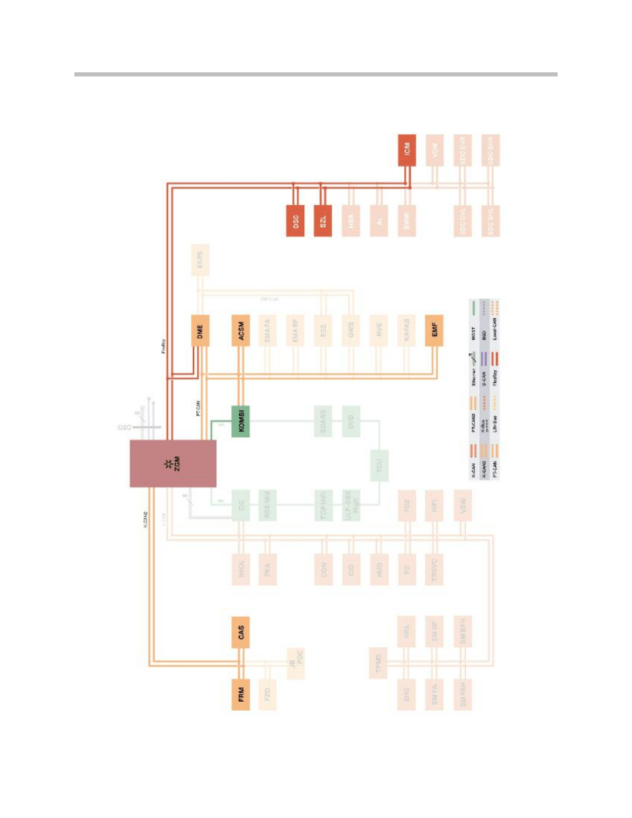
Bus System Overview for DSC and EMF
8
F01 Longitudinal Dynamics Systems

9
F01 Longitudinal Dynamics Systems
Index
Explanation
ACSM
Advanced Crash Safety Module
CAS
Car Access System
DME
Digital Motor Electronics
DSC
Dynamic Stability Control
EMF
Electromechanical Parking Brake
FRM
Footwell Module
ICM
Integrated Chassis Management
KOMBI
Instrument Cluster
SZL
Steering column switch cluster with steering-angle sensor
ZGM
Central Gateway Module
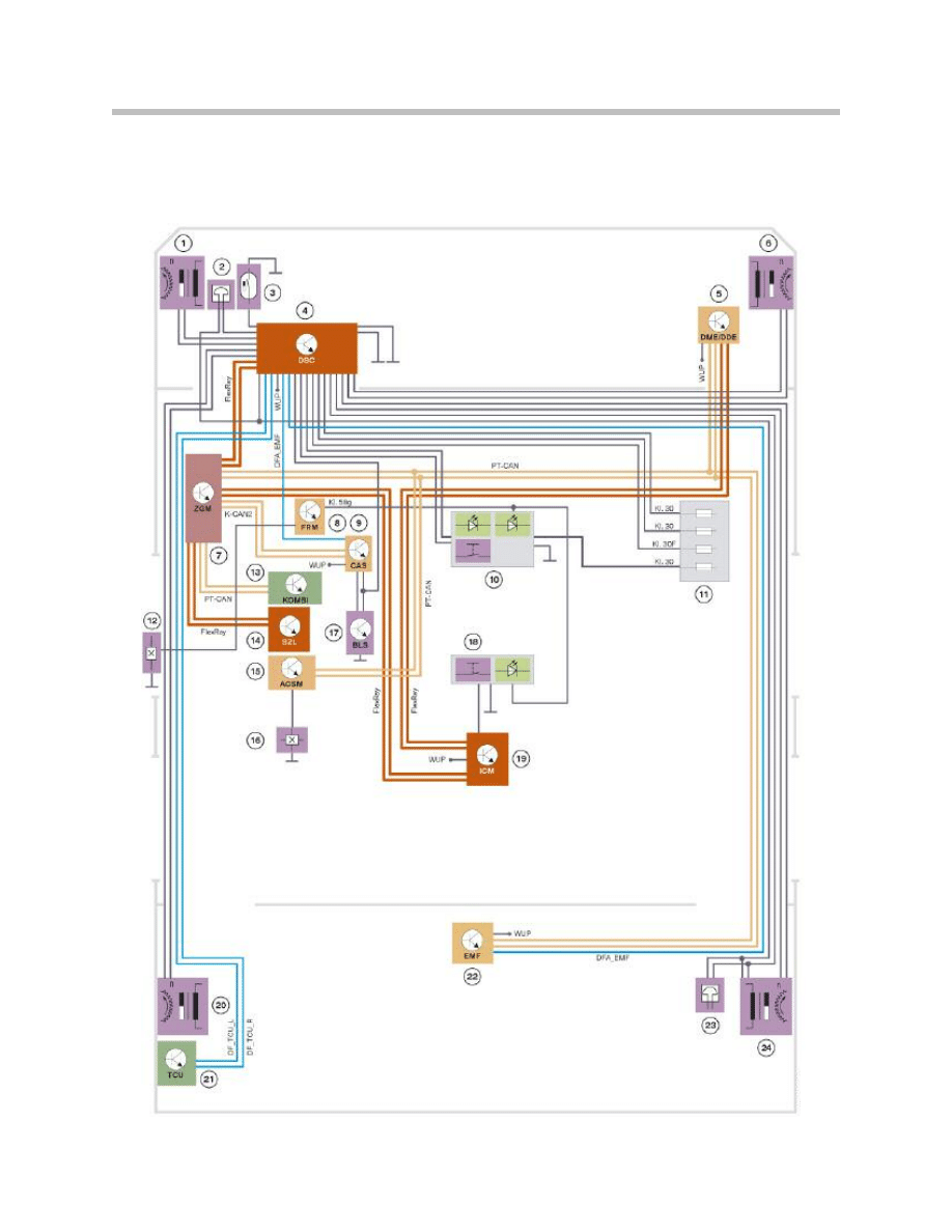
System Circuit Diagrams
Dynamic Stability Control
10
F01 Longitudinal Dynamics Systems

11
F01 Longitudinal Dynamics Systems
Index
Explanation
1
Wheel-speed sensor, front left
2
Brake pad wear sensor, front left
3
Brake fluid level switch
4
Dynamic stability control (DSC)
5
Digital Motor Electronics/Digital Diesel Electronics
6
Wheel-speed sensor, front right
7
Central Gateway Module
8
Footwell module
9
Car Access System
10
Auto-H button with function indicator and illumination
11
Fuses for DSC electronics, valves, pump motor and Auto-H button
(front fuse board, junction box electronics)
12
Door switch, driver's door
13
Instrument cluster
14
Steering column switch cluster with steering-angle sensor
15
Crash Safety Module
16
Seat belt buckle contact, driver's seat
17
Brake light switch
18
DTC button with illumination
19
Integrated Chassis Management
20
Wheel speed sensor, rear left
21
Telematics Control Unit
22
Electromechanical parking brake
23
Brake pad wear sensor, rear right
24
Wheel-speed sensor, rear right

DSC Functions
Overview
The Dynamic Stability Control on the F01/F02 (DSC F0x) essentially incorporates the
same functions as on the E70/E71 (DSC E7x).
As the DSC F0x is based on the same highly advanced technology as the DSC E7x, all
DSC functions on the F01/F02 achieve outstanding performance in terms of:
• dynamic response (brake pressure can be generated extremely quickly).
• control precision (brake pressure can be adjusted extremely precisely and without
significant fluctuation).
• noise emission (operation of the valves and the hydraulic pump is quieter than the
previous generations).
• tactile response (unpleasant feedback from the brake pedal has been substantially
reduced, e.g. pedal vibration during brake modulation).
Differences between the DSC functions on the E70/E71 and F01/F02 arise from the dif-
ferent drivetrain configurations (4-wheel drive/rear-wheel drive). Therefore, the DSC F0x
does not include the “Hill Descent Control (HDC)” function specific to 4-wheel drive
vehicles.
Instead of the 4-wheel-drive version of the automatic differential brake (ADB-X), the DSC
F0x uses the version for vehicles with rear-wheel drive (ADB).
A new subfunction of the ADB is that traction-control brake modulation is available even
when the DSC is switched off. This subfunction is called “Electronic Differential Lock
Control” and is described in one of the subsections below.
12
F01 Longitudinal Dynamics Systems
Functions

Symbols:
•
= Function active
X = Function has adapted control thresholds
⊕ = Can be switched on/off by driver
13
F01 Longitudinal Dynamics Systems
Function
DSC ON Traction DSC OFF
Anti-lock braking system (ABS)
•
•
•
Electronic brake force distribution (EBV)
•
•
•
Cornering Brake Control (CBC)
•
•
•
Engine drag torque control (MSR)
•
•
•
Automatic Stability Control (ASC)
•
X
Automatic Differential Brake (ADB)
•
X
X
Dynamic handling control (FDR)
•
X
Brake modulation for increased agility
•
•
Dry braking
•
•
•
Start assist
•
•
•
Brake readiness
•
•
•
Fading assistance
•
•
•
Dynamic Brake Control (DBC)
•
•
•
Automatic Hold combined with
electromechanical parking brake (EMF)
•
•
•
Run Flat Indicator (RPA)
•
•
•
Condition Based Service (CBS)
•
•
•
⊕
⊕
DSC and Integrated Chassis Management
14
F01 Longitudinal Dynamics Systems
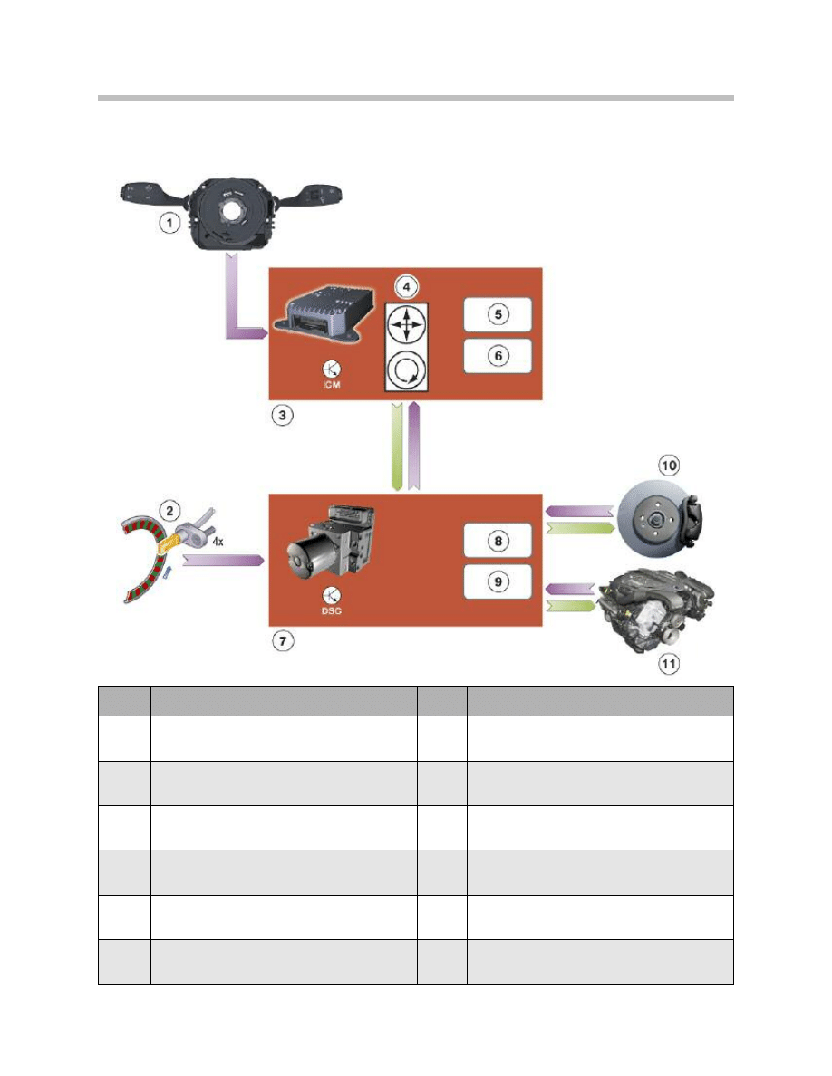
Index
Explanation
Index
Explanation
1
Steering column switch cluster with steering-
angle sensor
7
Dynamic Stability Control
2
Wheel speed sensors
8
"Dynamic handling control" function on DSC
3
Integrated Chassis Management
9
"Actuator control" function on DSC
4
Integral DSC sensor (linear acceleration, lateral
acceleration and yaw rate)
10
Brake
5
"Dynamic handling control" function on ICM
11
Drivetrain
6
"Actuator co-ordination" function on ICM
Input/output diagram: interaction of ICM and DSC

On previous vehicles, the DSC control unit contained the central dynamic handling con-
trol functions. A dynamic handling control complex remains part of the DSC F0x.
However, it is controlled by the central dynamic handling controller on the ICM (as are the
other dynamic handling systems).
The ICM calculates the current handling status and the vehicle response desired by the
driver. To do so, it makes use not only of the signals from the DSC sensor integrated in
the ICM but also of those from external sensors such as the steering angle sensor and
the wheel-speed sensors. If a difference between the response desired by the driver and
the reaction of the vehicle is detected, the central dynamic handling controller on the ICM
calculates a required compensatory yaw force.
The purpose of that yaw force is to bring about a yawing motion on the part of the vehicle
that is superimposed over the existing movement of the vehicle. In that way, the vehicle
handling can be corrected retrospectively, so to speak, when it threatens to become
unstable. The highly advanced DSC technology and the central dynamic handling
controller on the ICM even make is possible to optimize handling characteristics in
advance. One example of that is brake modulation for the purposes of improved agility,
which is described in one of the subsections further on.
Subordinate to the central dynamic handling controller on the ICM is an “actuator coordi-
nation” function. It decides whether and to what degree the DSC dynamic handling
system is to contribute to producing the required yaw force.
The required force is signalled to the DSC’s dynamic handling controller, which puts it
into action by operating the actuators represented by the brakes and drivetrain.
Simple implementation of the settings specified by the ICM is, however, not the only task
of the DSC’s dynamic handling controller on the F01/F02. It also continues to indepen-
dently perform the following original DSC functions:
• Anti-lock braking system (ABS)
• Cornering Brake Control (CBC)
• Automatic Stability Control (ASC)
• Engine drag torque control (MSR)
• Automatic Differential Brake (ADB)
15
F01 Longitudinal Dynamics Systems

The numerous additional functions over and above pure handling dynamics control are
also carried out largely independently by the DSC and without intervention by the ICM.
• Functions which help to reduce stopping distance: they include brake drying, brake
standby, brake fade prevention and dynamic brake control. The efficiency of the
brake standby and dynamic brake control functions is further improved in combina-
tion with the “ACC Stop & Go” optional extra.
• Convenience functions which make driving easier, e.g. Automatic Hold, which is per-
formed by the DSC and EMF in combination.
• The stresses on and wear of brake components are monitored with the aid of com-
putation models. Based on information such as brake pressure and brake tempera-
ture and the signals from the brake-pad wear sensors, a remaining service life
expressed as a mileage is calculated. The owner can view that information as a sub-
function of Condition Based Service and use it as an aid to planning servicing
appointments.
16
F01 Longitudinal Dynamics Systems
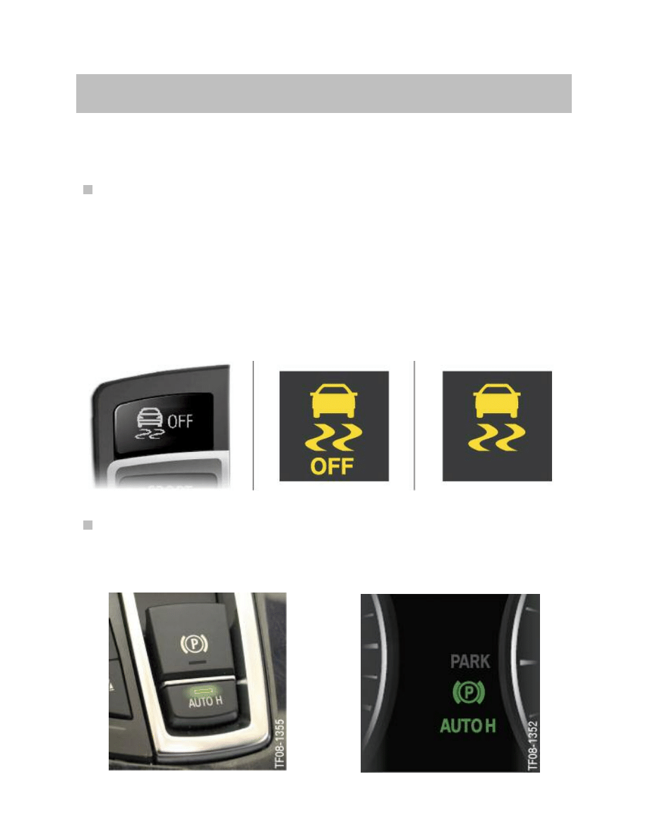
DSC Displays and Controls
New DSC symbols
There is a new set of symbols for Dynamic Stability Control displays and controls.
Starting on the F01/F02, this new DSC symbol set replaces the symbols previously used.
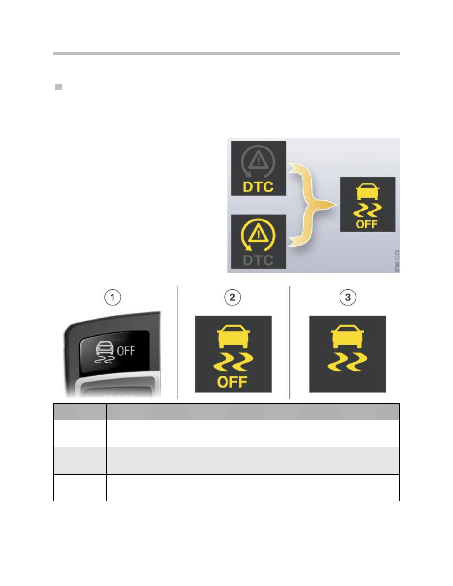
Previously there were two different
symbols displayed on the instrument clus-
ter for the statuses “DTC mode” and “DTC
off”.
As of launch of the F01/F02, there is now
only one symbol for both statuses.
However, the drive can distinguish
between the two statuses by means of
additional information in text form.
The new DSC symbol set relates not only
to the display but also the labeling of the
DTC button.
17
F01 Longitudinal Dynamics Systems
Index
Explanation
1
DTC button
2
DSC indicator and warning lamp on the instrument cluster:
– DSC switched off or
– DSC in DTC mode
3
DSC indicator and warning lamp on the instrument cluster:
– DSC control sequence active (flashing)
– DSC failure (permanently lit)
DSC indicator and warning lamp on the
instrument cluster:
DSC symbols

The new symbols will gradually be introduced on all new vehicles as they are phased in.
The reason for the change of symbols are the new legal requirements which oblige all car
manufacturers to use standardized display symbols. That will enable motorists to imme-
diately recognize the controls and displays of a DSC system as such regardless of the
brand of car they are driving.
The regulations also require that even merely limited DSC function must result in display
of the word “off”. That is the case in “DTC mode”, in which the stabilizing interventions
take place at a later stage.
DSC modes
As familiar from previous vehicles, the Dynamic Stability Control on F01/F02 incorporates
the following function modes:
• DSC on
• DTC (Dynamic Traction Control)
• DSC off
In the “DSC on” mode, all DSC functions are fully active. The stabilizing interventions in
brake and engine function take place at an early stage. That makes it easier for less
expert drivers to regain control of a vehicle that is becoming unstable.
In “DTC mode” the stabilizing interventions take place at a slightly later stage.
The Automatic Stability Control and Automatic Differential Brake functions allow a greater
degree of wheelspin. That improves traction when pulling away on loose surfaces such
as uncompacted snow. The dynamic handling control function does not come into
action until a larger sideslip angle is reached than in “DSC on” mode.
In “DSC off” mode, the stabilizing interventions by:
• the dynamic handling controller,
• the Automatic Stability Control and
are switched off.
Especially safety-critical DSC functions such as ABS remain fully active in all DSC
modes, however.
The mode “DSC off” is aimed at the undiluted driving experience, the direct connection
between the driver, vehicle and the road.
Integration in dynamic handling control
A new feature of the DSC modes on the F01/ F02 is that they are integrated in the
dynamic handling control function. Dynamic handling control is activated by means of
the handling setting switch and the DTC button.
Dynamic handling control enables the driver to choose one of six possible vehicle hand-
ing modes. The dynamic handling controller then controls all drivetrain and dynamic han-
dling systems simultaneously and in co-ordination with one another. The result is totally
harmonious handling in all modes.
18
F01 Longitudinal Dynamics Systems
19
F01 Longitudinal Dynamics Systems
The vehicle handling modes are called:
• Comfort
• Normal
• Sport
• Sport+
• Traction
• DSC off
When the vehicle is first started, the dynamic
handling controller is always in “Normal” mode.
The table below shows what mode the Dynamic
Stability Control is in for each of the vehicle han-
dling modes.
The other dynamic handling systems and
drivetrain control systems are switched in and
out as appropriate to the vehicle handling mode
selected.
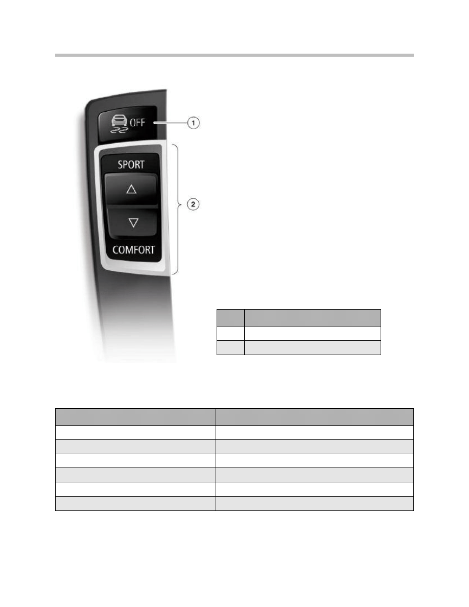
Vehicle handling mode
DSC mode
Comfort
DSC on
Normal
DSC on
Sport
DSC on
Sport +
DTC
Traction
DTC
DSC OFF
DSC off
Index
Explanation
1
DTC button
2
Handling setting switch
DTC button and handling setting switch

DSC Functions in Detail
ADB Active Even When DSC is Off
The DSC function ADB has been around for a long while on a wide variety of BMW vehi-
cles and especially in the form of the ADB-X version on the xDrive models.
If one of the wheels of a driven axle is spinning, it cannot transmit any driving force
(torque) to the road. And because the differential distributes the torque equally between
the two wheels, the other wheel on the axle can not transmit any driving force either.
ADB brakes the spinning wheel so that the driving torque and braking force are in equilib-
rium on that wheel. Then, by virtue of the differential, an equal amount of driving torque
is applied to the wheel that is not spinning. And because that wheel is offered grip by the
road surface, a driving force can be transmitted that results in forward motion of the
vehicle.
Thus ADB increases traction on slippery surfaces and has a similar effect to a differential
lock.
• On the xDrive models, ADB-X remains active even when the DSC is switch off in
order to achieve improved traction, especially when driving off road.
• On vehicles with rear-wheel drive, that individual braking of the driving wheels was
previously only active when the DSC was active or in “DTC” mode.
• On the new F01/F02 (and the top 1 Series and 3 Series models) that ADB subfunc-
tion remains active even when the DSC is switched off.
That function is called “Electronic Differential Lock Control” and uses the DSC to
emulate the effect of a differential lock on the driving wheels. In contrast with previous
arrangements, such brake modulation for the purposes of increasing drive transmission
takes places even if the driver has switched off the DSC.
20
F01 Longitudinal Dynamics Systems
Brake Modulation for Increasing Agility
The highly advanced hardware of the DSC F0x enables brake modulation to be carried
out without unpleasant feedback for the driver. On the F01/F02, that capability is utilized
to influence the vehicle’s self-steering characteristics is a specifically targeted way.
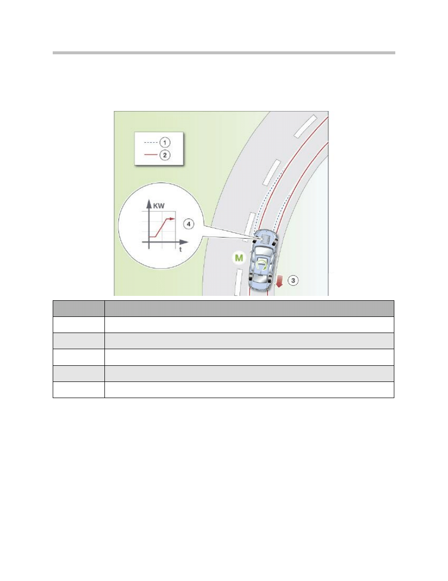
If the vehicle begins to understeer, e.g. when cornering quickly, the central dynamic han-
dling controller on the ICM detects the very first indications that it is starting to happen.
A required setting is transmitted to the DSC requiring it to apply the brake on the rear
wheel on the inside of the bend. The DSC sensitively applies the required setting and
without generating a level of noise perceptible by the driver. The uneven braking effect
thus produced, creates a yaw force acting around the vehicle’s center of gravity. As a
result, the vehicle turns towards the inside of the bend, doesn’t understeer and corners
with absolutely neutral handling.
This type of brake modulation increases road safety because it prevents the vehicle drift-
ing towards the outside of the bend. The disadvantage, however, is that the vehicle is
slowed slightly by the application of the brake and thus a degree of momentum is lost.
21
F01 Longitudinal Dynamics Systems
Index
Explanation
1
Course of an understeering vehicle
2
Course of a vehicle with neutral handling
3
Individual modulation of brakes to prevent understeer
4
Increased engine torque to compensate for braking force
M
Yaw force acting on the vehicle as a result of individual modulation of brakes

22
F01 Longitudinal Dynamics Systems
Therefore, in typical BMW fashion, the solution is taken a step further. Whenever handling
stability considerations allow, the engine torque is increased simultaneously with brake
application. The higher engine torque is transmitted to the road by the wheel on the out-
side of the bend that is not being braked. The control strategy ensures that the increase
exactly matches the retardation by the brake application.
While that DSC function is active, there is no display of any kind on the instrument cluster.
In that way, highly advanced components (DSC) and intelligent control strategies are
combined to produce an overall effect that substantially improves agility without impairing
the handling stability of the vehicle.
Automatic Hold
This function has been around since the E65, on which it was called “Auto-P”. The
Automatic Hold function was also used on the E70/E71.
Although the Automatic Hold function is computed on the DSC control unit, it can not be
put into effect without an electromechanical parking brake (EMF). The EMF is always
required whenever the DSC hydraulic modulator is unable to permanently hold the vehi-
cle stationary. In particular, that is the case when the engine is switched off.
When the Automatic Hold function is active, the driver first of all brakes the vehicle to a
standstill. It is then held stationary by the DSC hydraulic modulator. That is achieved by
maintaining the final brake pressure applied by the driver. If the vehicle starts to roll on an
incline, the DSC hydraulic modulator actively generates brake pressure.
Pressing the accelerator causes the brake pressure to be released and the vehicle starts
to move again. Automatic holding and releasing of the brakes in that way makes driving in
easier in conditions such as urban traffic and stopping at traffic lights or stop-and-go dri-
ving in traffic tailbacks.
After the engine is started, the function can be activated until the next time the engine is
switched off. To do so, the driver’s door must be closed and the driver’s seatbelt fas-
tened. The function can, of course, also be manually deactivated before the engine is
switched.
The footwell module reads the signal from the door switch. The ACSM control unit analy-
ses the signal from the seat belt buckle contact. The two signals are transmitted to the
DSC control unit via the bus systems. One signal that is not analysed for the Automatic
Hold function on the F01/F02 is the driver’s seat occupancy signal.
Conversely, the Automatic Hold function is automatically deactivated if the driver’s door is
opened and the driver’s seatbelt unfastened. To prevent the vehicle rolling away in that
situation, the EMF parking mode is activated. As long as the engine is running, the park-
ing mode is effected by means of the DSC hydraulic modulator. If the driver switches the
engine off, the function is taken over by the EMF actuator unit.
Note: Before the vehicle is driven into a car wash, the Automatic Hold function
has to be deactivated as otherwise the brakes are applied when the vehi-
cle is stationary and it can not be rolled.
The Automatic Hold function is activated and deactivated by means of the button marked
“AUTO H” on the center console. Activation of the function is acknowledged by the func-
tion indicator lamp (green LED in the button). Whenever the green LED is lit, the
Automatic Hold function is active. The status of the Automatic Hold function is also indi-
cated on the instrument cluster.
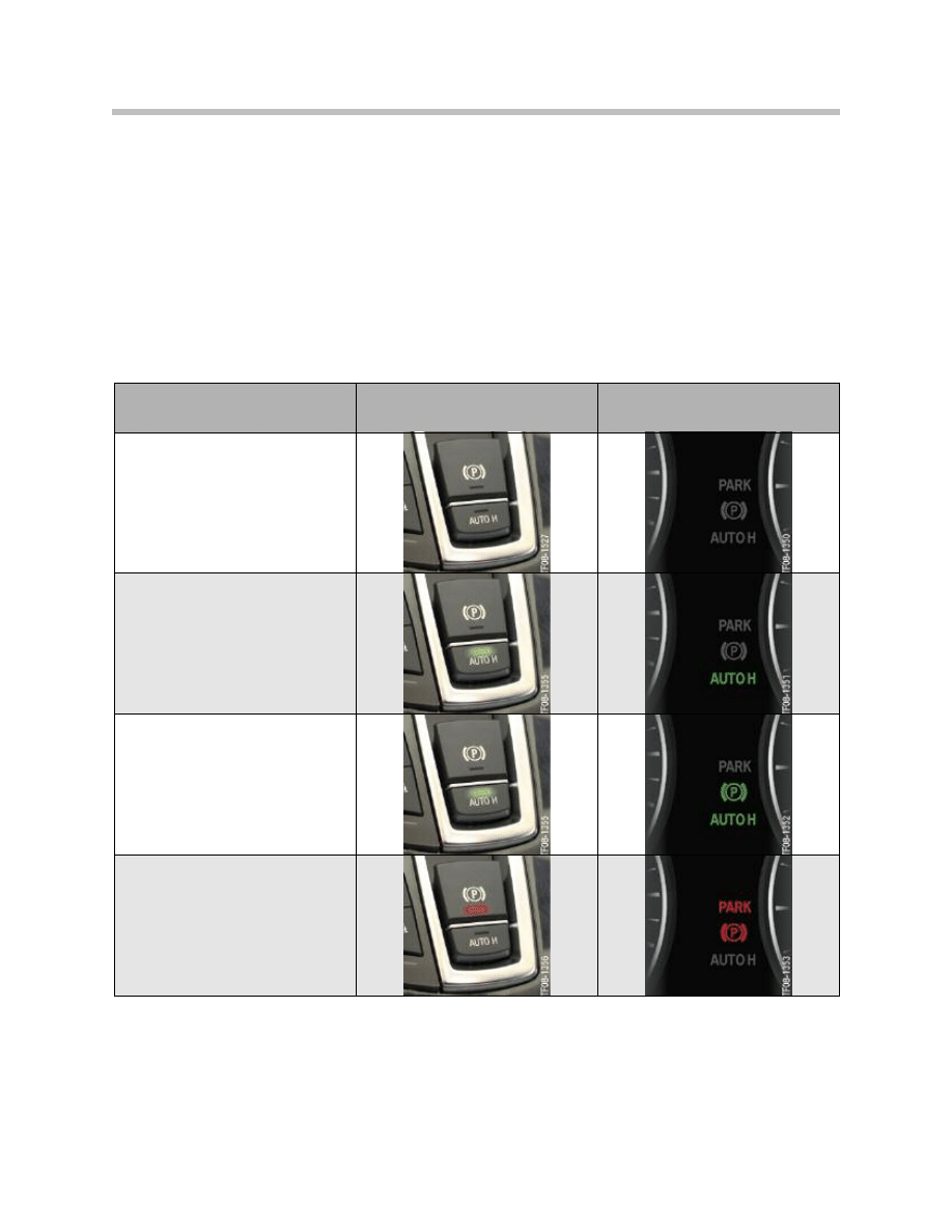
The various function statuses and how they are indicated are summarized below.
23
F01 Longitudinal Dynamics Systems
Status of Automatic
Hold function
Function indicator
lamps in buttons
Display on
instrument cluster
Switched off
Switched on and on standby
(e.g. when vehicle is moving)
Switched on and active
(vehicle is being held stationary)
Deactivated by driver getting out
of vehicle or switching engine off

When Automatic Hold is holding the vehicle stationary, two additional internal DSC sub-
functions are activated: roll-away monitoring and slide detection.
The roll-away monitoring function is described in the section “EMF functions”.
The slide detection function is designed to intervene if the vehicle starts to slide after
stopping, i.e. if all four stationary wheels start to slip. That can happen on a steep slope
when the road is slippery, for instance. If the driver were holding the vehicle stationary and
became aware of such a situation, he/she would release the brake. In that way the vehicle
can at least be steered as it rolls down the slope.
The slide detection function is based on exactly the same principle. When the vehicle is
being held stationary by Automatic Hold, the slide detection function monitors the signals
from the wheel-speed sensors. The DSC releases the pressure on one of the brakes in
alternation while keeping the others under pressure. If the wheel-speed sensor registers
a movement from the wheel on which the brake is released, then obviously the entire
vehicle must be moving. That means that the other wheels, on which the brakes are
applied, must be sliding while locked. Under those circumstances, the condition “sliding”
would be detected.
The response to detection of sliding is progressive release of brake pressure so that the
vehicle becomes steerable. The driver is made aware of the critical situation by a Check
Control message and an audible warning signal.
Interface for Adaptive Braking Assistance
The function “Adaptive Braking Assistance” implemented as a co-ordinated strategy by
the DSC and Adaptive Cruise Control with Stop & Go function is also available on the
F01/F02. It is a function that was previously introduced on the E60/E61 LCI.
The interface relates to two functions on the Dynamic Stability Control:
• brake standby and
• dynamic braking control.
“Brake standby” can be activated by a request signal transmitted by the ICM control unit.
That happens when a potential collision situation has been detected with the aid of the
radar sensors. And, of course, “brake standby” is also activated if the internal DSC criteria
familiar from previous models are met (minimum speed, rapid release of accelerator
pedal).
The threshold for triggering dynamic braking control can be influenced by ACC Stop &
Go. If a potential collision situation is detected, the ICM control unit sends out a signal
requesting lowering of the activation threshold. To be precise, the activation threshold is
the rate of increase of brake pressure applied by the driver that has to be exceeded in
order to dynamic braking control (braking assistance). That makes it easier for the driver to
trigger dynamic braking control. This function is the only means by which a driver braking
hesitantly can activate dynamic braking control.
24
F01 Longitudinal Dynamics Systems

25
F01 Longitudinal Dynamics Systems
NOTES
PAGE

DSC Components
DSC Unit
The DSC unit on the F01/F02 essentially uses the same technology as on the E70/E71.
Versions
The DSC unit comprises the DSC control unit and the hydraulic modulator. The two are
attached to one another in such a way as to form a waterproof unit.
The repair kits available are either
• the complete DSC unit with pre-filled hydraulic modulator or
• the DSC control unit on its own.
There is a seal integrated in the casing of the DSC control unit at precisely the point
where it joins the hydraulic modulator. That is the reason why the DSC control unit can
be replaced separately (seal is replaced at the same time). The hydraulic modulator, by
contrast, can not be replaced separately because the seal would be damaged when the
two parts were separated. The required degree of waterproofing would then no longer
be provided.
There are two versions of the DSC unit which differ by virtue of the number of pressure
sensors fitted.
The DSC unit with only one pressure sensor uses a computation model to determine
the pressures in the front and rear brake circuits. The degree of accuracy obtained is suf-
ficient for the functions of the dynamic handling systems and the cruise control with
braking function. The optional extras ACC and ACC Stop & Go require a higher degree
of accuracy for determining the brake pressure generated and modulated by the
Dynamic Stability Control. Therefore, the two additional brake sensors are fitted in
the front and rear brake circuits.
26
F01 Longitudinal Dynamics Systems
System Components
Optional extra
ACC / ACC Stop & Go
Number of pressure sensors
Brake pressures measured
No
1
Pressure applied by driver
Yes
3
Pressure applied by driver
Pressure in front-wheel brake circuit
Pressure in rear-wheel brake circuit

Hydraulic modulator
With its highly advanced pump design, the hydraulic modulator also offers an enhanced
degree of control accuracy. There are 2 groups of 3 pump elements with a diameter of
6.5mm and intake-optimized units. This pump design produces, firstly, substantially
improved pressure generation dynamics. And secondly, the pressure increments during
pressure generation are smaller. Together with the improved design of the valves, the
overall effect is less pedal feedback during brake modulation.
For the driver this is noticeable in as far as the pedal pulsation can now only be felt very
slightly during ABS braking. There is a pressure sensor for detecting the pressure applied
by the driver in the hydraulic modulator.
27
F01 Longitudinal Dynamics Systems
DSC control unit
Like the hydraulic modulator, the DSC control unit on the F01/F02 is also based on the
one used on the E70/E71.
Specifically, the following special features and differences should be noted:
• FlexRay connection
• Wiring of the new DTC button
• Wheel-speed signals for electromechanical parking brake, Car Access System
and Telematic Control Unit
28
F01 Longitudinal Dynamics Systems
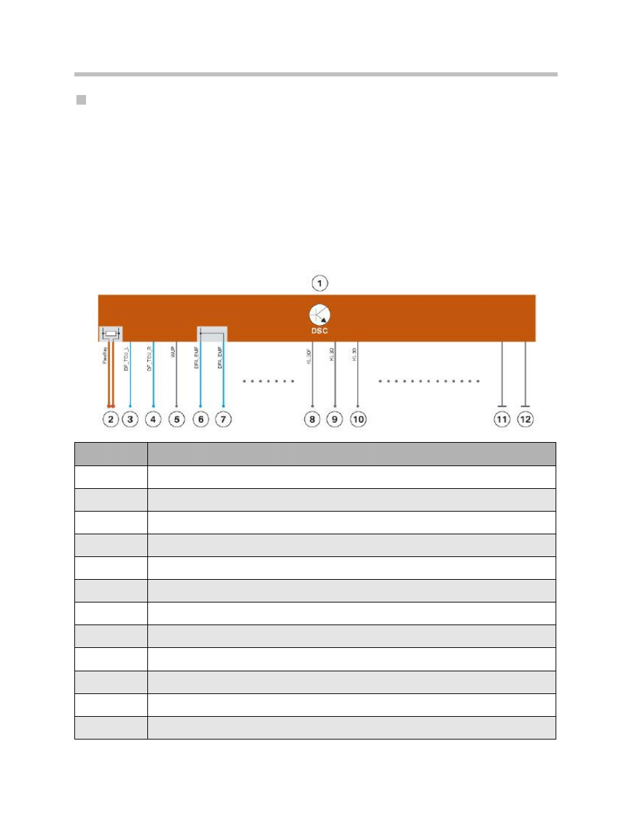
Index
Explanation
1
DSC control unit
2
FlexRay input with terminal resistor
3
DF_TCU_L, front left wheel-speed signal for Telematic Control Unit (TCU)
4
DF_TCU_R, front right wheel-speed signal for TCU
5
WUP, wake-up line
6
DFA_EMF, wheel-speed signal for Car Access System (CAS)
7
DFA_EMF, wheel-speed signal for electromechanical parking brake (EMF)
8
Power supply for DSC module (Terminal 30F)
9
Power supply for valves (Terminal 30)
10
Power supply for pump motor (Terminal 30)
11
Ground for DSC module
12
Ground for valves and pump motor
Overview of important connections on DSC control unit

The DSC control unit on the F01/F02 is connected to the FlexRay and not, as on previ-
ous vehicles, to the PT-CAN and F-CAN.
The FlexRay is brought to the DSC control unit (from the ZGM) and ends there. The DSC
control unit is thus the terminal node of the FlexRay. Accordingly, it contains a terminal
resistor for the FlexRay.
On previous vehicles, the DTC button was electrically analysed by the IHKA control unit,
for instance (E70/E71). On those vehicles, the button operation signal is transmitted via
bus systems to the DSC control unit.
The new DTC button on the F01/F02 is connected to the ICM control unit instead. The
DTC button and the associated function is part of the “dynamic handling control” function
on the F01/F02. As that, in turn, is computed on the ICM control unit, the DTC button
has been connected to the ICM control unit. The ICM control unit then signals the
appropriate vehicle handling mode via the FlexRay. The DSC control unit analyses the
signalled mode and adapts its function accordingly.
For the EMF and CAS control units, the information about vehicle standstill is of particular
importance. For those two systems, the DSC control unit provides the DFA_EMF signal.
It is a calculated signal computed from the speeds of the two rear wheels. It is transmitted
as a pulse-width modulated signal on a dedicated line to the EMF and CAS control units.
If there is a Telematic Control Unit (TCU) fitted on the vehicle but no navigation system,
the TCU control unit has to take on the task of determining vehicle location. That is nec-
essary for the manual and automatic emergency call functions. The signals from the GPS
aerial are insufficient for that purpose as it has to be possible to determine the vehicle’s
location even if the GPS signals are temporarily unavailable. In that case, the TCU control
unit uses the speed signals from the two front wheels to calculate the road speed and
changes of direction when cornering. The wheel-speed signals are provided by the DSC
control unit and transmitted to the TCU control unit by a directly wired connection
(DF_TCU_L and DF_TCU_R).
The power supply for the DSC unit is split into three: control unit, valves and pump motor
are supplied by separate leads. That prevents interference from the load circuits (induc-
tive loads) being transferred to the electronic circuitry.
The DSC control unit is also connected to the wake-up line. The wake-up line is used to
wake up the DSC control unit.
Location and repair
The DSC unit is located in the vehicle underbody, set back somewhat from the wheel
arch. That location applies to both left and right-hand-drive vehicles.
29
F01 Longitudinal Dynamics Systems
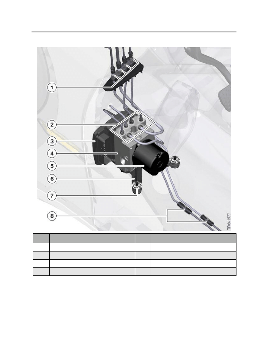
Location of DSC unit on F01/F02
Six short lengths of hydraulic pipe are connected to the DSC unit by screw-fit unions.
Four of those hydraulic pipes run upwards from the hydraulic modulator and terminate at
a block with quick-release unions. They are connected by those quick-release unions to
the pipes running off to other parts of the vehicle. Specifically, that is the two pipes to the
left and right front brakes and the two pipes to the tandem master cylinder.
30
F01 Longitudinal Dynamics Systems
Index
Explanation
Index
Explanation
1
Quick-release hydraulic pipe unions, 4 off
5
DSC pump motor
2
Screw-fit hydraulic pipe unions, 6 off
6
DSC unit mounting bracket
3
DSC control unit
7
Bolt fixing with vibration damper for DSC unit
4
DSC valve manifold
8
Screw-fit hydraulic pipe unions, 2 off

The two remaining hydraulic pipes run to the rear. They are connected by quick-fit unions
to the pipes running off to other parts of the vehicle. In this case, they lead to the left and
right rear brakes.
If the DSC unit has to be replaced, first of all the vehicle underbody trim has to be
removed in the appropriate places. When the DSC unit is removed, the six short lengths
of hydraulic pipe referred to above are removed with it. Therefore, before removal, the four
quick-release unions (4) and the two screw-fit unions (8) have to be disconnected. The
short lengths of hydraulic pipe subsequently have to be removed and fitted to the new
DSC unit.
Only after the DSC unit has been removed can the DSC control unit be separated from
the hydraulic modulator, if necessary, and new one fitted.
The braking system must always be bled whenever the DSC unit has been removed and
refitted/replaced.
The precise procedures for the individual repair operations in connection with the DSC
unit are described in the Repair Instructions.
31
F01 Longitudinal Dynamics Systems
Sensors for DSC
Wheel speed sensors
The same type of wheel-speed sensor is used on the F01/F02 as on the E70/E71
(DF11i made by Robert Bosch GmbH).
They are four active wheel-speed sensors, all four of which are connected by dedicated
two-core leads directly to the DSC control unit. The wheel-speed data is transmitted to
the DSC control unit as a pulse-width-modulated signal.
The active wheel speed sensors enable detection of direction of rotation and clearance
gap.
Detection of direction of rotation is required for the hill-start assistance and Automatic
Hold functions, among others. The clearance-gap sensing function allows sensor posi-
tioning faults to be detected. If there is too much play in the wheel bearings, the wheel-
speed signal can also become unreliable. That situation is also detectable by the clear-
ance-gap sensing capability of the wheel-speed sensors.
It can therefore be guaranteed that the DSC control unit only operates on the basis of
correctly detected wheel-speed signals.
32
F01 Longitudinal Dynamics Systems
TF04-5465
1
2
3
Index
Explanation
Index
Explanation
1
Sensor ring/ferromagnetic wheel bearing seal carrier
3
Sensor housing
2
IC sensor with Hall sensor
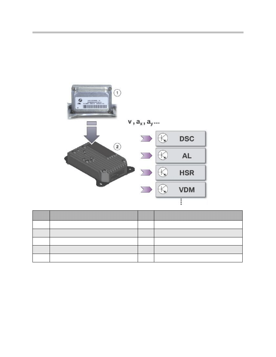
The DSC control unit broadcasts the wheel-DSC sensor in ICM speed sensor signals via
the FlexRay network and directly wired links to the other systems on the vehicle.
The DSC sensor, which was previously a separate component, has been integrated in the
ICM control unit on the F01/F02.
33
F01 Longitudinal Dynamics Systems
Index
Explanation
Index
Explanation
1
DSC sensor integrated in ICM control unit
DSC
Dynamic Stability Control
2
ICM control unit
AL
Active steering
v
Road speed
HSR
Rear suspension slip angle control
ax
Linear acceleration
VDM
Vertical Dynamics Management
ay
Transverse acceleration
Dynamic handling signals provided by ICM control unit
With the aid of the signals from those integrated sensors and the wheel-speed signals
provided by the DSC control unit, the ICM control unit calculates the following variables
that are of significance for the vehicle’s dynamic handling status:
• Road speed
• Linear acceleration and pitch
• Lateral acceleration and roll
• Yaw rate
Steering-angle sensor in SZL
With the aid of the steering-angle sensor, the SZL is able to provide the following signals
via the FlexRay bus system:
• Steering angle
• Steering rate
Those variables are used as input signals by the dynamic handling systems to determine
the driver’s intention when cornering. On the F01/F02 it is important to note that the
steering-angle sensor signals are first analysed by the ICM control unit and then provided
to control units of the other dynamic handling systems as the “effective steering-angle
signal”.
Detection of the steering angle and the steering rate is performed by an optical proximity
sensor, the optical steering angle sensor.
34
F01 Longitudinal Dynamics Systems
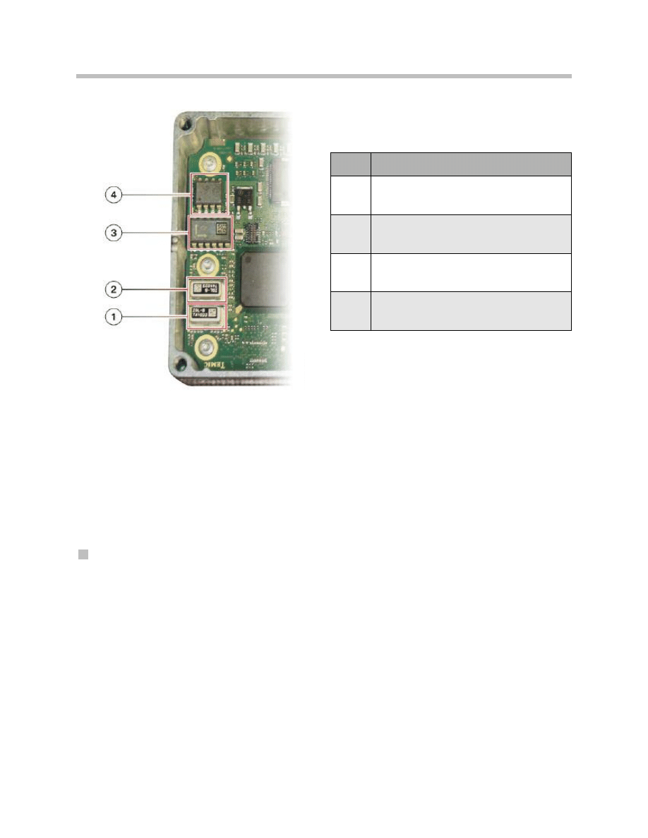
DSC sensor integrated in ICM control unit
Index
Explanation
1
Yaw rate sensor
2
Second, back-up yaw rate sensor
3
Linear and lateral acceleration sensor
4
Second, back-up lateral acceleration sensor
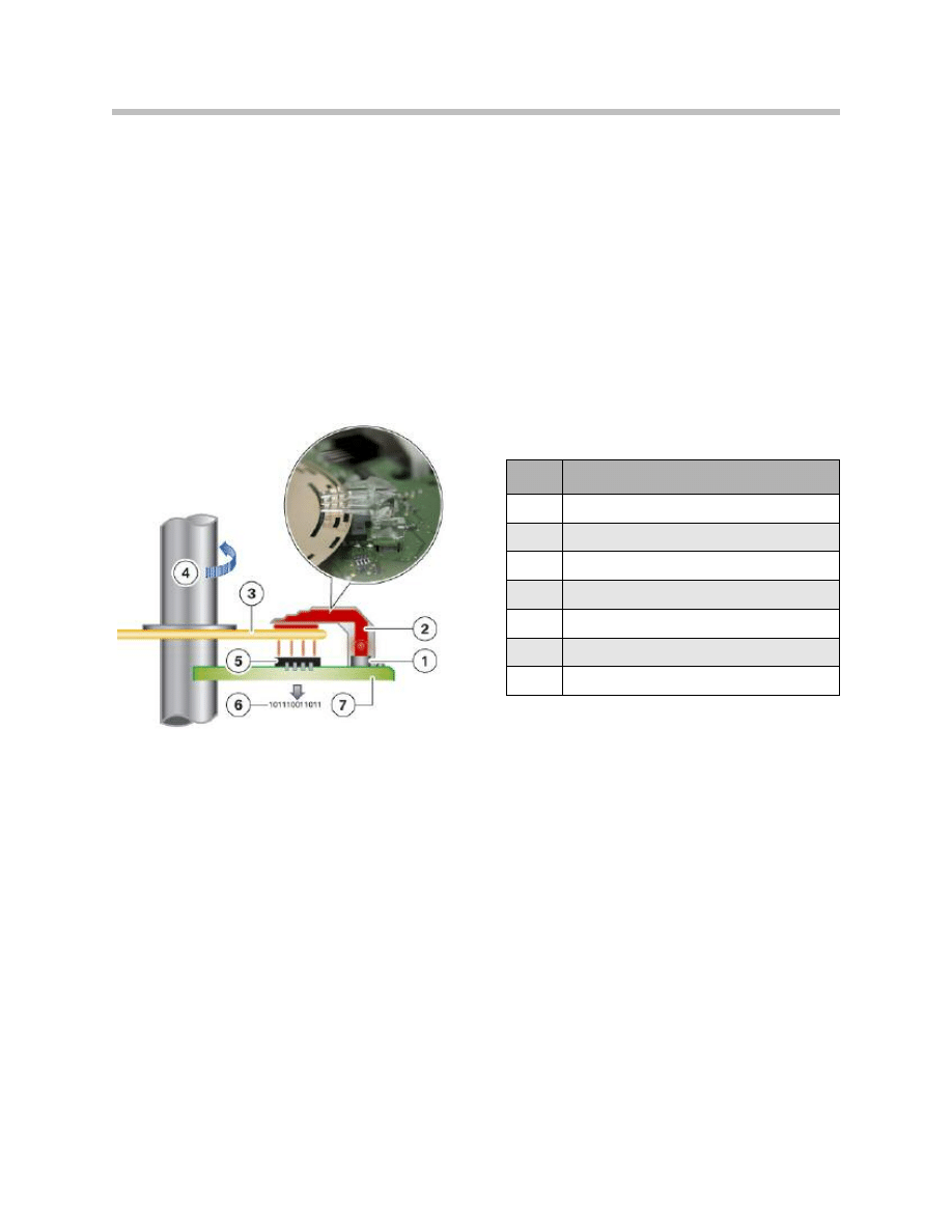
Information such as the absolute steering angle or the steering wheel rotation is calculat-
ed. The optical steering-angle sensor detects steering angles from -640° to +640°.
If the SZL suffers a power loss, e.g. if the battery terminals are disconnected, the steering
wheel rotation data is lost. The SZL is then initially unable to determine the absolute
steering angle and can only identify the relative steering angle.
This temporary fault status can be remedied by turning the steering wheel from lock to
lock. Alternatively, the SZL can detect the straight-ahead position from the wheel-speed
signals from the front wheels when driving in a straight line.
In either case, the absolute steering angle is then known again.
Note: If at least one of the following conditions exists, the steering column
switch cluster has to perform steering-angle sensor calibration:
• Wheel alignment carried out
• SZL replaced or re-programmed
• Diagnosis system test procedure specifies calibration.
Note: When calibrating the steering angle sensor, the instructions given by the
diagnosis system must be followed precisely.
The vehicle must be standing on a level surface during calibration. The
steering wheel must be aligned visually in the straight-ahead position.
35
F01 Longitudinal Dynamics Systems
Index
Explanation
1
Light-emitting diode
2
Fiber optics unit
3
Code disc
4
Steering column
5
Photo-transistors
6
Output: Conversion to electrical signals
7
PCB
Schematic diagram of optical steering-angle
sensor on F01/F02
Important Points for Servicing and Repairs
Dynamic Stability Control (DSC)
General details
Note: The modes “Dynamic Traction Control” (DTC) and “DSC off” are still
used on the F01/ F02. However, on the F01/F02, the DSC modes are
integrated in the “dynamic handling control” function, which rather
than controlling individual systems, controls the system complex of
all drivetrain and dynamic handling systems.
Note: There is a new set of symbols for DSC displays and controls on the
F01/F02.
Automatic hold function
The Automatic Hold function is activated/ deactivated by means of a button on the cen-
ter console control panel. The Automatic Hold status is indicated by the function indica-
tor lamp on the button and an indicator lamp on the instrument cluster.
36
F01 Longitudinal Dynamics Systems
Service Information
DSC symbols

For Automatic Hold to be activated, the driver's seatbelt must be fastened and the dri-
ver's door closed.
Note: Before the vehicle is driven into a car wash, the Automatic Hold function
has to be deactivated as otherwise the brakes are applied when the vehi-
cle is stationary and it can not be rolled.
DSC unit
There are two versions of the DSC unit which have either one or three pressure sensor(s)
(vehicles without/with “Active Cruise Control” optional extra)
Note: The repair kits available are either
• the complete DSC unit with pre-filled hydraulic modulator or
• the DSC control unit on its own.
The hydraulic modulator can not be replaced separately.
Note: The DSC unit is located in the vehicle underbody, set back somewhat
from the wheel arch.
Note: If the DSC unit has to be replaced, first of all the vehicle underbody trim
has to be removed.
When the DSC unit is removed, the six short lengths of hydraulic pipe are
removed with it. Therefore, before removal, the four quick-release
unions at the top and the two screw-fit unions at the bottom have to be
disconnected from the hydraulic pipes.
The short lengths of hydraulic pipe subsequently have to be removed
and fitted to the new DSC unit.
37
F01 Longitudinal Dynamics Systems

Signals and sensors
Note: The wheel speed sensors are connected to the DSC control unit. The
DSC control unit processes the wheel-speed sensor signals and broad-
casts them via the FlexRay network to other systems, in particular the
Integrated Chassis Management.
Note: The DSC control unit does not only provide the wheel-speed signals in
the form of bus signals. They are transmitted to the EMF, CAS and TCU
control units by direct wired links.
Note: The DSC sensor, which was a separate component on previous vehicles,
has been integrated in the ICM control unit. The ICM control unit
processes the important sensor signals for the Dynamic Stability
Control and supplies them in the form of bus signals. Those signals are:
• Yaw rate
• Transverse acceleration
• Linear acceleration
• Steering angle
• Vehicle speed.
Note: The DSC sensor in the ICM control unit has to be calibrated if
• the ICM control unit has been replaced or
• the testing sequence on the diagnosis system demands it on the
basis of a fault memory entry.
Calibration must be performed with the vehicle on a surface that is level
both lengthways and side to side. Terminal 15 must also be switched on.
38
F01 Longitudinal Dynamics Systems

Note: If at least one of the following conditions exists, the steering column
switch cluster has to perform steering-angle sensor calibration:
• Wheel alignment carried out
• SZL replaced or re-programmed
• Diagnosis system test procedure specifies calibration.
Note: When calibrating the steering angle sensor, the instructions given by
the diagnosis system must be followed precisely.
The vehicle must be standing on a level surface during calibration. The
steering wheel must be aligned visually in the straight-ahead position.
39
F01 Longitudinal Dynamics Systems
40
F01 Longitudinal Dynamics Systems
Overview of EMF Functions
Normal Operation
Parking brake application
The driver can activate the EMF parking brake function by pulling on the parking brake
button. Thus the way in which the parking brake button is operated emulates the action
of a handbrake lever.
The signal from the parking brake button is read by the EMF control unit and transmitted
to the DSC control unit as a bus signal. The DSC control unit then decides whether to
use the DSC hydraulic modulator or the EMF actuator unit to implement the parking
brake function. If the engine is running, the vehicle is held stationary by using the DSC
hydraulic modulator; otherwise the EMF actuator unit is used.
The parking brake function is possible at any logical terminal status, i.e. at:
• Terminal 0
• Terminal R
• Terminal 15 (and Terminal 50)
Parking brake application at Terminal 0 is specifically made possible by the fact that the
EMF control unit is supplied by Terminal 30 and the parking brake button is connected
directly to the EMF control unit. If the driver operates the parking brake button at Terminal
0, the EMF control unit is woken up. The EMF control unit in turn wakes up the other
control units on the vehicle. Only then can the EMF control unit receive the important sig-
nals relating to vehicle standstill. In addition, the changed status of the parking brake can
be displayed after the system has been woken up.
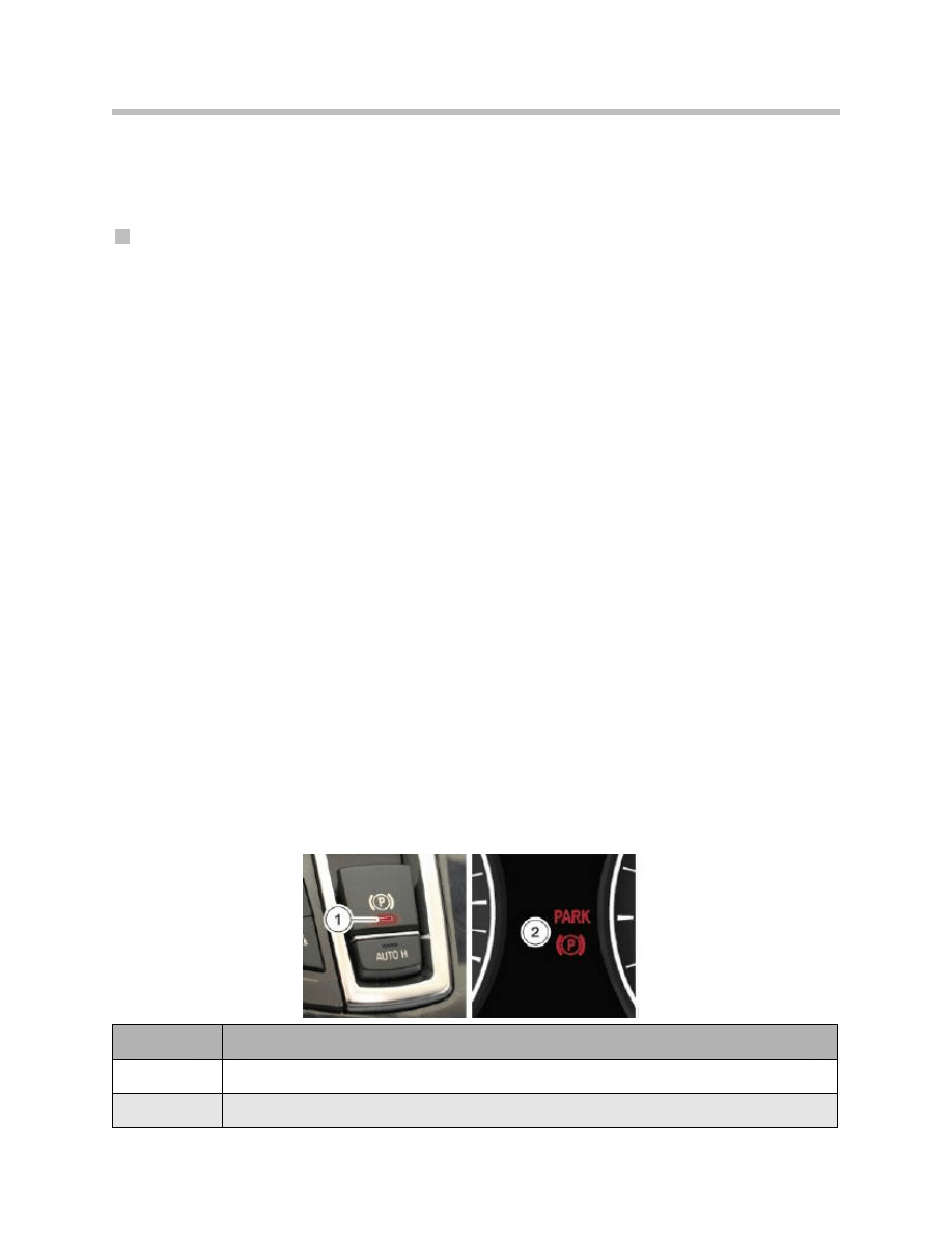
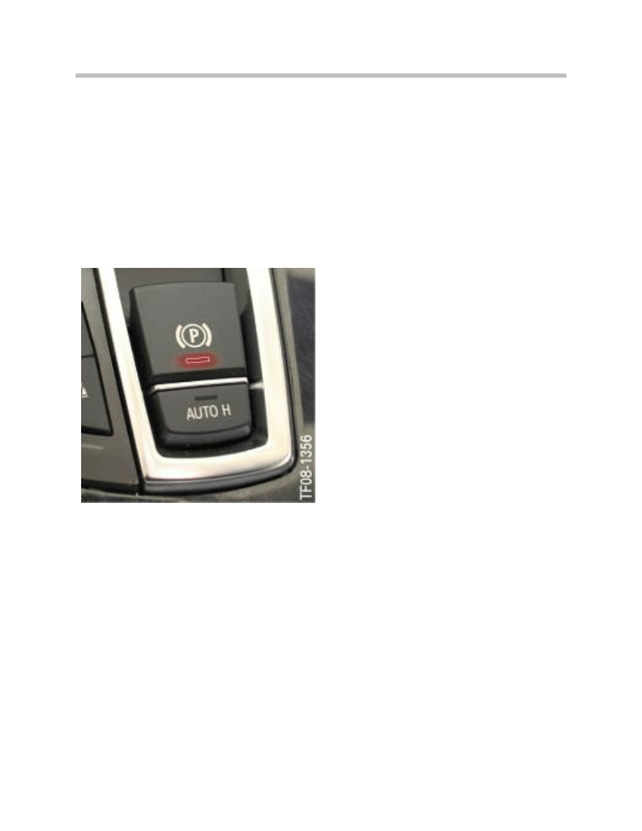
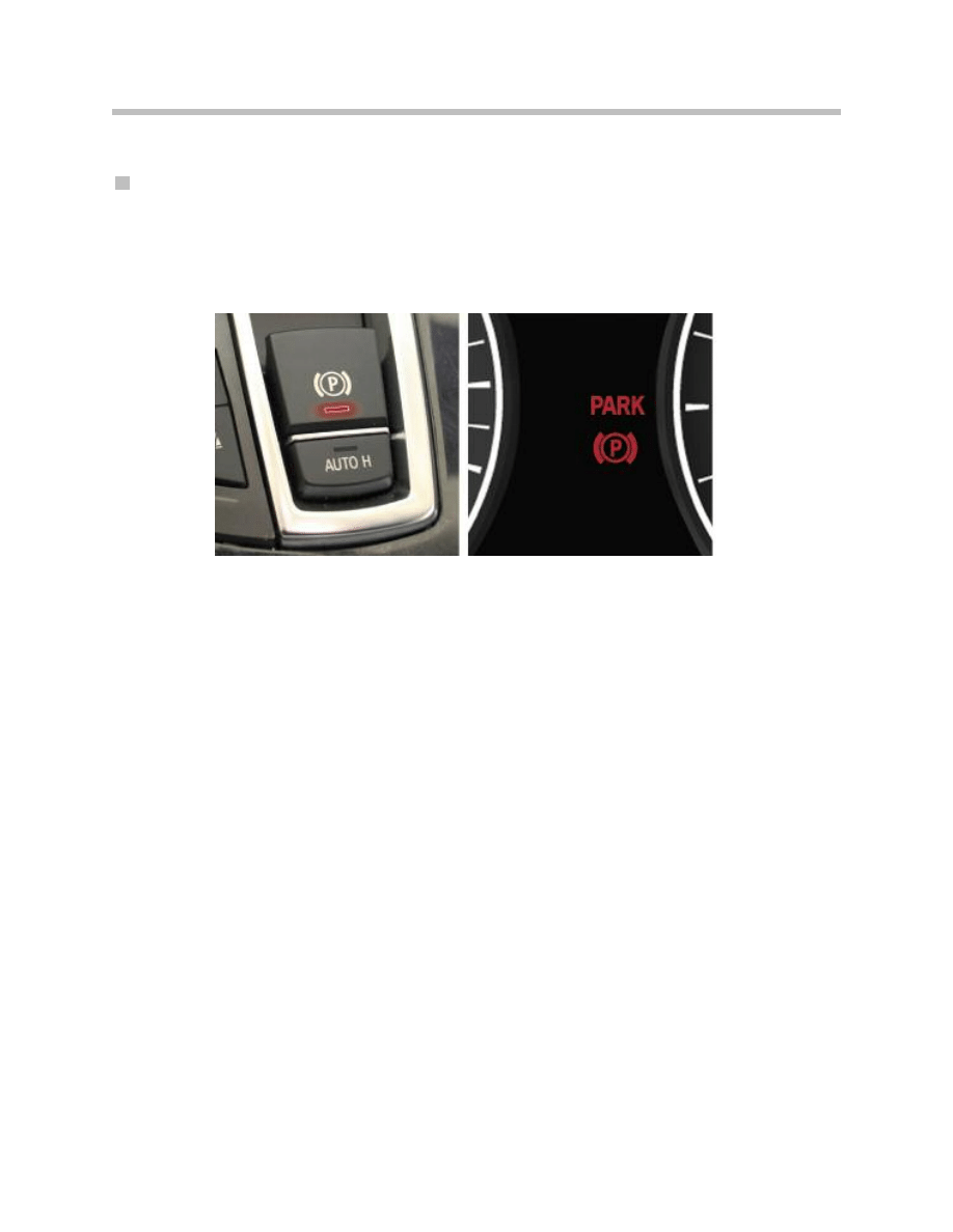
The status “parking brake on” is indicated by a red LED on the parking brake button and
an indicator lamp on the instrument cluster.
The driver does not have to operate any other controls to apply the parking brake.
Once the parking brake is on, pulling the parking brake button again has no effect.
Index
Explanation
1
Function indicator lamp on parking brake button
2
Indicator lamp on instrument cluster
Indication of "parking brake on"
41
F01 Longitudinal Dynamics Systems
Roll-away monitoring
The roll-away monitoring function is computed on the DSC control unit. It is active while
the vehicle is being held stationary by:
• the DSC hydraulic modulator or
• the EMF actuator unit.
The condition for activation of roll-away monitoring is thus that either the EMF parking
brake function or the Automatic Hold function is active.
Roll-away monitoring observes the signals from the wheel-speed sensors. If any of the
wheel-speed sensors signals movement of the wheel, that indicates that the vehicle is
rolling. Since, however, the vehicle is supposed to be stationary by virtue of the brake
pressure applied by the hydraulic system or the EMF actuator, the roll-away monitoring
function has to intervene. The hydraulic brake pressure is increased by control signals to
the DSC hydraulic modulator or EMF electric motor in order to increase the braking force.
In that way the rolling is counteracted.
Release
In similar fashion to the operation of a handbrake lever, the EMF is released by pushing
the parking brake button in.
But in order that the parking brake function is actually cancelled, Terminal 15 must also
be on and one of the following conditions must be met:
• Brake pedal depressed or
• Automatic transmission parking lock engaged.
That prevents the vehicle rolling away if another occupant of the vehicle apart from the
driver presses in the parking brake button (child safety feature).
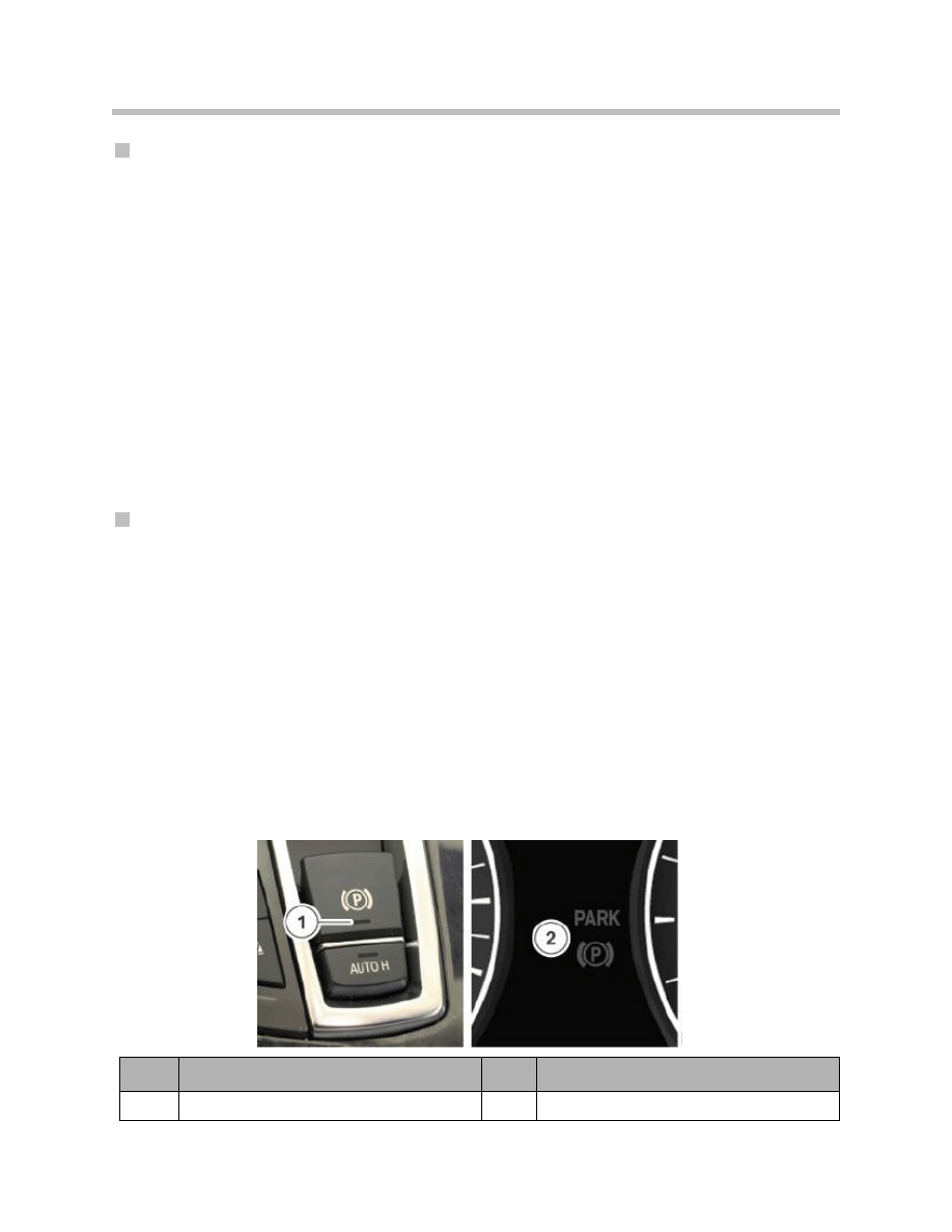
Once the parking brake is released, the function indicator lamp on the parking brake but-
ton and the indicator lamp on the instrument cluster go out.
Index
Explanation
Index
Explanation
1
Function indicator lamp on parking brake button
2
Indicator lamp on instrument cluster
Indication of "parking brake released"

42
F01 Longitudinal Dynamics Systems
Dynamic braking
The law requires that vehicles have two means of applying the brakes. On the F01/F02,
the second means (the brake pedal being the first) is the parking brake button on the
center console.
If the parking brake button is pulled out while the vehicle is in motion, a defined degree of
braking is applied by the DSC system. That function is intended for emergency situations
in which the driver is unable to apply the brakes by pressing the brake pedal. Other occu-
pants of the vehicle can also bring the vehicle to a standstill in that way if, for example, the
driver suddenly loses consciousness.
Dynamic braking hydraulically applies brake pressure at all four brakes. The stabilization
functions of Dynamic Stability Control remain fully functional and the brake lights are
switched on. That represents a major advantage over a manual parking brake.
Braking takes place only while the parking brake button is pulled out. The degree of
deceleration set by the DSC is increased progressively from initially 3 m/s2 to 5 m/s2.
During dynamic braking, the parking brake indicator light on the instrument cluster comes
on. In addition, a Check Control message and an audible warning signal are issued to
make the driver aware of the critical situation.
If the driver uses the brake pedal and the parking brake button at the same time to slow
down, the DSC control unit prioritizes. The greater braking requirement is put into effect.
If dynamic braking is continued to the point of standstill, the vehicle continues to be held
stationary after the parking brake button is released. The indicator lamp on the instrument
cluster remains on. The driver can then release the parking brake (as described above).
43
F01 Longitudinal Dynamics Systems
Emergency release
A mechanical emergency release facility is provided in order to be able to release the
parking brake in the event of the electromechanical actuator unit failing or insufficient
power supply.
Note: Caution: secure vehicle to prevent it rolling before operating the emer-
gency release!
Note: After a power supply failure, it may still not be possible to move the vehi-
cle even after releasing the brake with the emergency release facility.
The automatic transmission parking lock may still be engaged.
In that case, the parking brake must first be released with the emergency
release facility. Then the automatic transmission parking lock must be
released using the emergency release facility. To do so, the appropriate
tool must remain engaged in the parking lock emergency release.
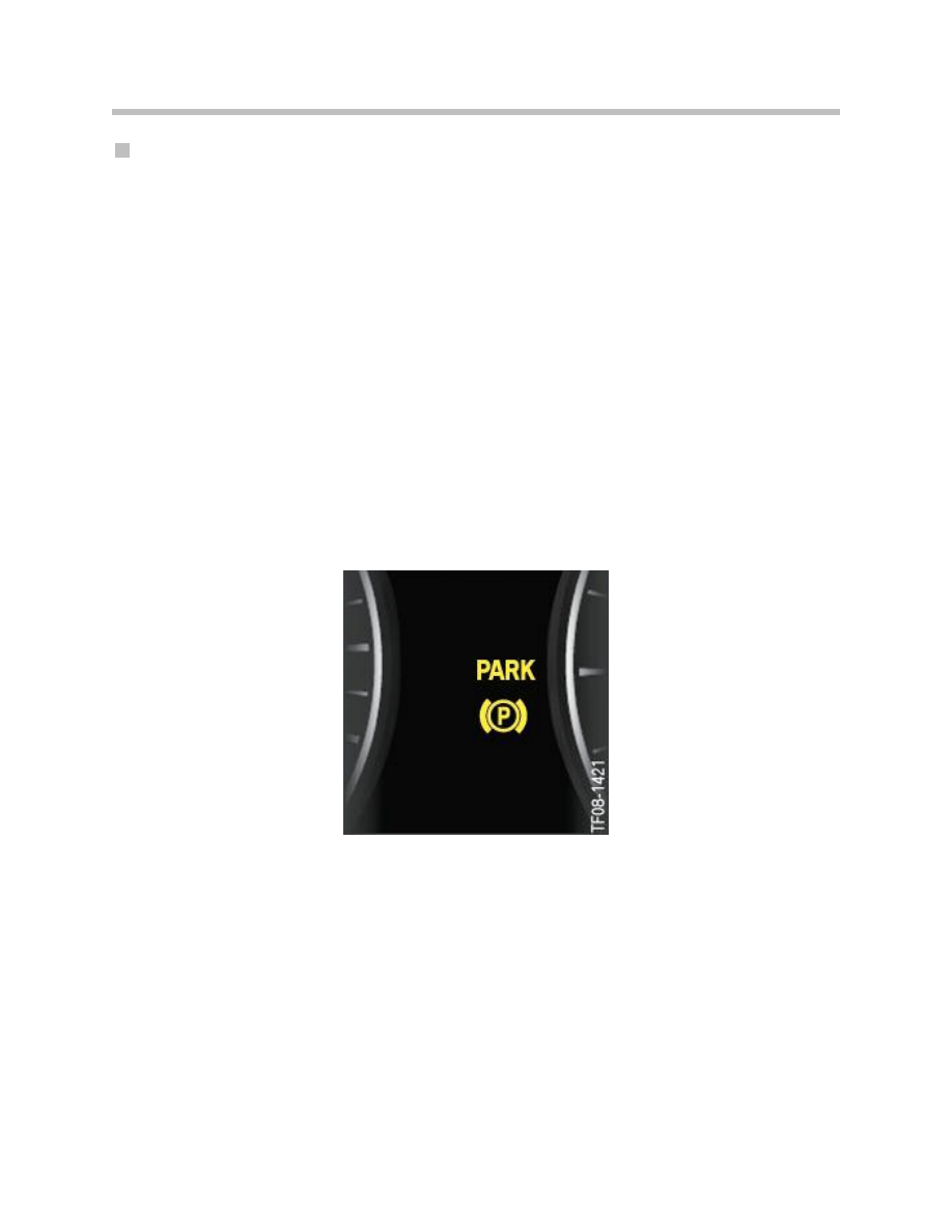
The parking brake emergency release status is indicated on the instrument cluster.
The parking brake indicator lamp shows yellow.
The driver is shown the same indication (together with a check control message) if the
parking brake has a fault.
When the parking brake is to be used again after an emergency release, that can not be
done mechanically but only electrically. It requires pushing in the parking brake button
once as if to release the parking brake. The familiar conditions for releasing the parking
brake must also be met.
Indication of “parking brake emergency release/fault”
44
F01 Longitudinal Dynamics Systems
Service Function
Installation Mode
EMF installation mode is required for the purposes of replacing the EMF actuator unit or
the brake cables. The EMF can be set to installation mode with the aid of the BMW diag-
nosis system. This mode is comprized of two subfunctions:
• Setting the EMF actuator unit to the installation position
• Preventing the EMF parking brake function.
To set the unit to the installation position, the brake cables are extended to the maximum
length. That is the essential requirement for being able to remove and refit the cables.
While work is being carried out on the actuator unit, the brake cables or the duo-servo
parking brake, the EMF must not be inadvertently or deliberately applied. Doing so would
risk causing injury. Installation mode prevents the EMF parking brake function.
That means that pulling out the parking brake button as if to apply the parking brake has
no effect.
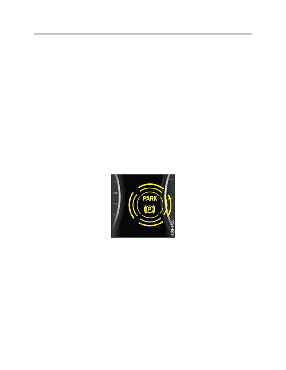
Installation mode is indicated on the instrument cluster by the parking brake indicator
lamp flashing yellow.
Installation mode can be cancelled in two ways:
• By the performing the service function “Reset installation mode” using the BMW
diagnosis system
• By driving the vehicle; when doing so, a minimum speed must be exceeded.
Once installation mode has been successfully cancelled, the parking-brake indicator lamp
on the instrument panel goes out.
Indication of parking-brake installation mode

45
F01 Longitudinal Dynamics Systems
Running-in the Brakes
The function for running-in the parking brakes only has to be carried out if
• the linings of the duo-servo parking brakes have been replaced or
• the rear brake discs have been replaced.
In either case, a material/surface pairing then initially exists which does not yet have the
optimum frictional properties. That means that the required braking forces could not be
achieved.
The brake running-in function removes play between the two surfaces forming the fric-
tional pairing, i.e. the brake linings and the inside of the brake disc recess. It also wears-in
the surfaces. Both operations are essential to achieving the required frictional coefficient
between the two surfaces.
The brake running-in function is prepared with the aid of the BMW diagnosis system.
It is started by pulling out the parking brake button once. The parking brake indicator lamp
flashes red throughout the entire sequence.
While running-in the parking brakes, the EMF applies a defined force to the duo-servo
parking brakes. That force is substantially lower than the brake force required to hold the
vehicle stationary. The rear wheels are then rotated either on a brake dynamometer or by
driving the vehicle on the road.
Note: The precise procedure for running-in the parking brakes is described in
the Repair Instructions under the heading “Adjusting the parking
brake”. The instructions given there must be followed exactly.
46
F01 Longitudinal Dynamics Systems
EMF Components
This section deals only with the special features of the actuator unit and the controls for
the electromechanical parking brake. On the F01/F02, as on numerous other BMW
models, the braking force for the parking brake is produced by the familiar duo-servo
parking brakes on the two rear wheels.
EMF Actuator Unit
The complete EMF actuator unit and especially the electric motor and gearing have been
optimized for use on the F01/F02. That is noticeable in particular by quieter operation
during actuation.
The EMF actuator unit is made up of the following main components:
• EMF control unit
• Electric motor
• Gearbox
• Force sensor
Those components are housed in a plastic casing that can not be opened. In the event of
a fault, the EMF actuator unit can only be replaced as a complete unit.

47
F01 Longitudinal Dynamics Systems
EMF control unit
As on the E70, the EMF control unit on the F01/F02 is integrated in the actuator unit
casing and is also identical in design to the one on the E70. It is the actuation controller
for the EMF functions. It therefore controls the electric motor and reads the signals from
the force sensor.
The most important control signal from outside is that from the parking brake button.
The parking brake button is directly wired to the EMF control unit.
The EMF control unit is connected to the PTCAN. Integrated in the EMF control unit is
one of the two terminal resistors for the PT-CAN. The EMF control unit communicates via
the PT-CAN with its most important partner, the DSC control unit. As the DSC control
unit is only connected to the FlexRay, the central gateway module is required to transfer
the signals between the PT-CAN and the FlexRay.
A special place among the input signals is occupied by the information relating to vehicle
standstill. The EMF actuator unit must not be activated while the vehicle is moving but
rather only when it is stationary. Otherwise, the vehicle handling would become unstable
due to the rear wheels locking up. The EMF control unit detects vehicle standstill on the
basis of the following three input signals:
• Road speed (provided by Integrated Chassis Management via bus systems)
• Rear axle speed (provided by engine management via PT-CAN)
• Wheel-speed signal “DFA_EMF” (calculated by Dynamic Stability Control and trans-
mitted via direct wired link to EMF control unit).
Only when those three signals definitively indicate vehicle standstill does the EMF control
unit allow operation of the actuator unit.
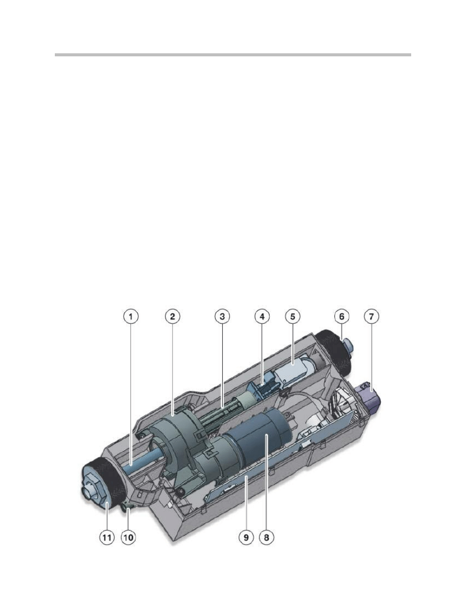
Index
Explanation
Index
Explanation
1
Spindle
7
Connector
2
Gearbox
8
Electric motor
3
Splined shaft
9
Control unit circuit board
4
Emergency release mechanism
10
Entry/exit for emergency release cable
5
Force sensor
11
Sleeve nut for left brake cable
6
Sleeve nut for right brake cable
Overview of important connections on EMF actuator unit
48
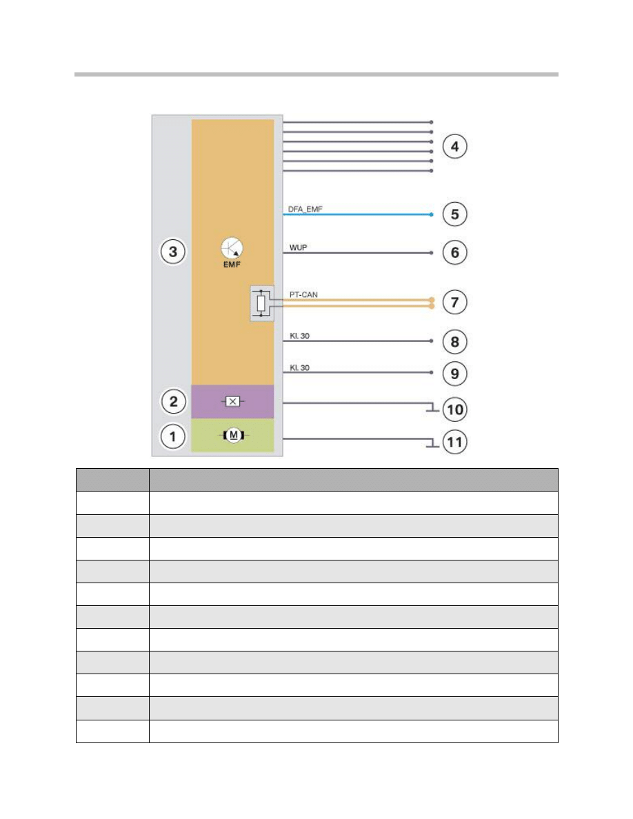
F01 Longitudinal Dynamics Systems
Index
Explanation
1
Electric motor
2
Force sensor
3
EMF control unit
4
Signal leads for parking brake button and function indicator lamp
5
DFA_EMF, wheel-speed signal from DSC
6
WUP, wake-up line
7
PT-CAN input with terminal resistor
8
Power supply for EMF control unit (Terminal 30)
9
Power supply for electric motor (Terminal 30)
10
Earth for EMF control unit
11
Earth for electric motor

49
F01 Longitudinal Dynamics Systems
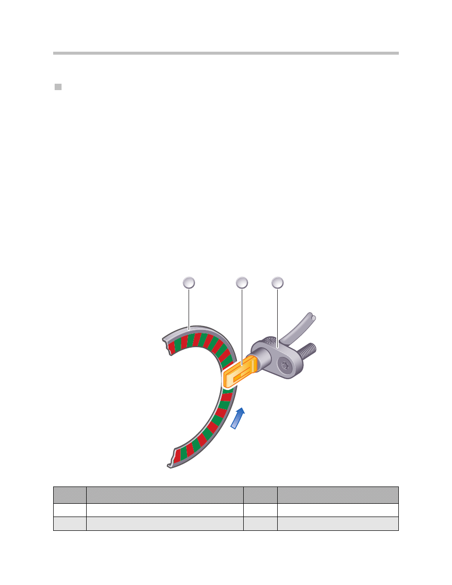
Force sensor
Technically speaking, the force sensor is a travel sensor that operates according to the
Hall effect. Between the two brake cables there is a spring with a defined strength. That
strength is stored on the EMF control unit. Therefore, it can determine the force acting
on the cables from the change in the length of the spring.
The force acting on the brake cables is an important input variable for the control algo-
rithm on the EMF control unit. When the parking brake is applied, the EMF control unit
has to ensure that a specific required force is applied to the brake cables. The EMF con-
trol unit calculates that required force on the brake cables directly from the legally required
holding force on the wheels. The latter has to be great enough to safely keep the vehicle
stationary on an uphill or downhill gradient of up to 20 %.
Over the life of the cables, a slight degree of stretching can occur. However, that does not
corrupt the force-sensor signal. The spring does not, of course, start to compress until a
force is acting on the cables. If, due to stretching, the cables are initially loose when in the
released position, then no force is acting on the spring. Only when a force is applied to
the cables, and, therefore, to the spring by operation of the electric motor does the spring
compress. Then the force sensor sends the appropriate signal to the EMF control unit.
50
F01 Longitudinal Dynamics Systems
Bracket
To attach the EMF actuator unit to the vehicle’s structural components, a multi-angled
bracket is used. That design allows the EMF actuator unit itself to remain virtually identi-
cal in dimensions (to the one on the E70/ E71). Adaptation to the geometry of the
surrounding components on the different vehicles is achieved by the specific design of
the mounting bracket.
The bracket for the EMF actuator unit locates at the top on a boss on the rear suspension
subframe. Fixing of the bracket at the bottom differs according to whether the vehicle is
fitted with Integrated Active Steering or not. Vehicles with Integrated Active Steering have
an actuator for the rear-wheel steering on the rear suspension. The bracket for the EMF
actuator then rests on the rear-wheel steering actuator bracket. The two brackets are
joined by two bolts.
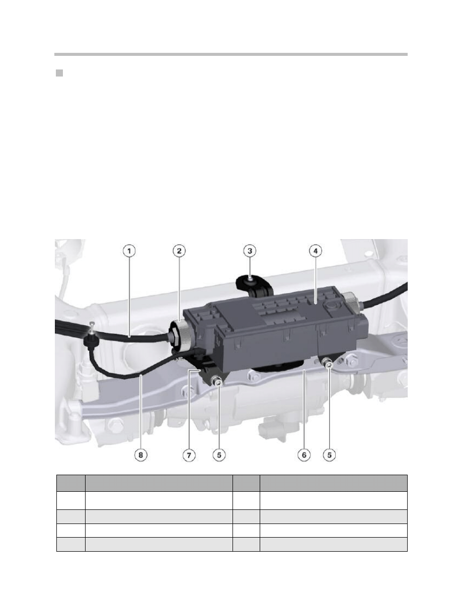
Index
Explanation
Index
Explanation
1
Left brake cable
5
Bolt joining EMF actuator and
HSR actuator brackets
2
Sleeve nut for left brake cable
6
HSR actuator bracket
3
Boss on rear suspension subframe
7
EMF actuator unit bracket
4
EMF actuator unit
8
Emergency release cable
EMF actuator unit bracket and HSR actuator
51
F01 Longitudinal Dynamics Systems
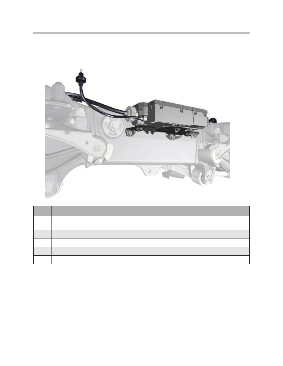
On vehicles without Integrated Active Steering, the bracket for the EMF actuator unit is
attached to the rear suspension subframe by the same two bolts.
The bracket and the EMF actuator unit itself are also attached to one another by bolts.
If replacement is necessary, both the bracket and the EMF actuator unit itself can be
ordered as separate parts.
Index
Explanation
Index
Explanation
1
Bowden cable, emergency release
6
Bolt fixing EMF actuator to rear
suspension subframe
2
Left brake cable
7
EMF actuator unit bracket
3
Sleeve nut for left brake cable
8
Rear suspension subframe
4
EMF actuating unit
9
Track rod
5
Bolt fixing EMF actuator to mounting bracket
EMF actuator unit bracket without HSR actuator
Controls
Parking Brake Button
The parking brake button supplies the EMF control unit with the button operation signal.
The signal is duplicated on the parking brake button and transmitted to the EMF control
unit via double direct wired connections. It not only enables the EMF control unit to dis-
tinguish between the resting position and the two directions of operation (release/apply).
Faults can also be detected (e.g. broken circuit, short circuit). If such a fault is detected,
the function of the parking brake can still be maintained in most cases.
In contrast with the button on the E70/E71, the parking brake button on the F01/F02 has
a function indicator lamp. It is an LED that tells the driver when the parking brake is on.
The EMF control unit directly controls that LED.
It is important to note that the button directly behind it for the Automatic Hold function is
not wired to the EMF control unit but to the DSC control unit.
52
F01 Longitudinal Dynamics Systems
Parking brake button with function indicator lamp
53
F01 Longitudinal Dynamics Systems
Emergency release
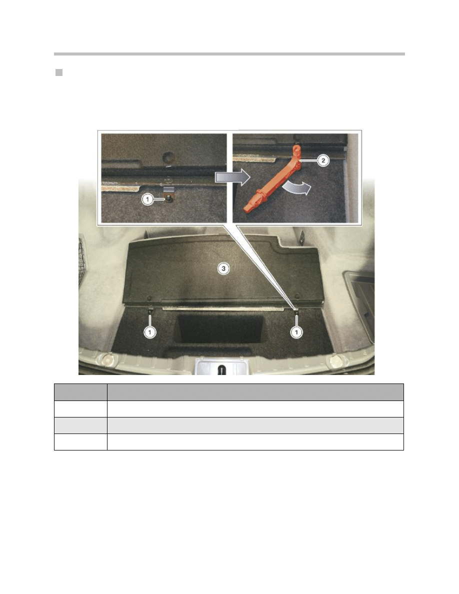
The cable for emergency release of the parking brake is accessible via the trunk.
However, the cable is located underneath the trunk floor trim, which on the F01/F02
can not be simply taken out.
Under a flap there are two plastic nuts which fix be removed. The emergency release tool
(red the trunk floor trim in place. Those nuts must T-shaped handle) incorporates a plastic
first be undone before the trunk floor trim can socket for unscrewing the nuts.
Index
Explanation
1
Plastic nut (size 10mm)
2
Emergency release tool
3
Trunk floor trim
Removing trunk floor trim on F01/F02
54
F01 Longitudinal Dynamics Systems
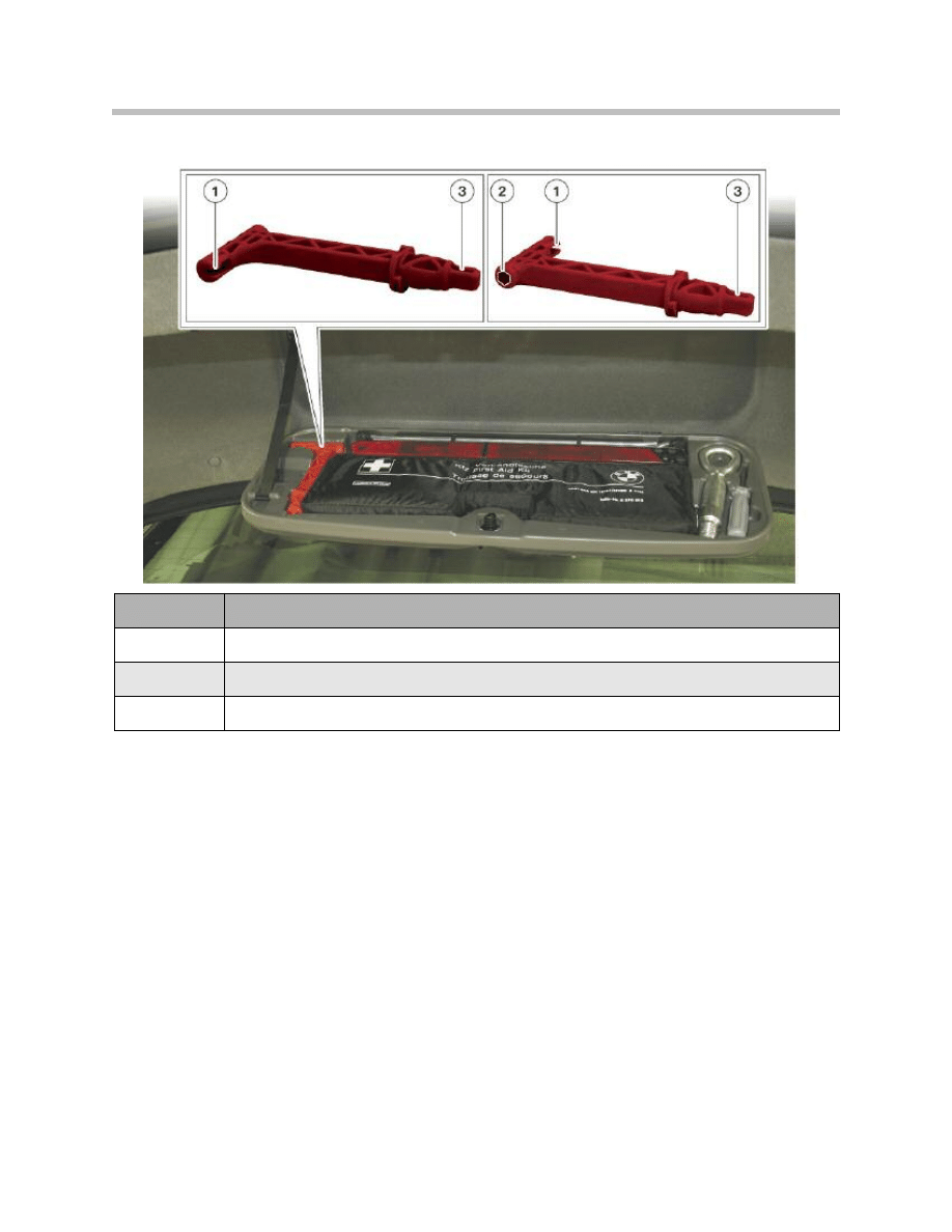
Once the trunk floor trim has been removed, the emergency release cable is directly
accessible. The handle of the release tool is hooked onto the end of the emergency
release cable by means of the slot provided.
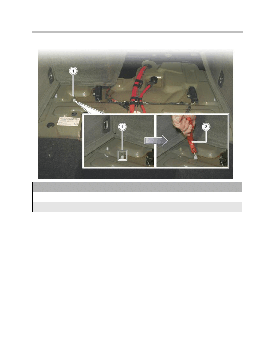
Pulling the cable up operates the emergency release mechanism in the EMF actuator
unit. There is a noticeable jolt when it releases. The cables to the two duo-servo parking
brakes are then released from the force acting on them. The parking brake is thus
released.
Index
Explanation
1
Slot for accepting the EMF emergency release cable
2
Socket (size 10mm) for unscrewing the plastic nuts on the trunk floor trim
3
Square key for releasing the automatic transmission parking lock
Emergency release tool on F01/F02
55
F01 Longitudinal Dynamics Systems
Index
Explanation
1
Bowden cable, emergency release (EMF)
2
Emergency release tool
Emergency release of electromechanical parking brake on F01/F02
Electromechanical Parking Brake (EMF)
General details
The electromechanical parking brake (EMF) is applied/released by means of the parking
brake button on the center console control panel. The parking brake status is indicated
by the function indicator lamp on the button and an indicator lamp on the instrument
cluster.
The EMF can be applied in all logical terminal statuses (Terminal 0, Terminal R, Terminal
15, Terminal 50). The conditions for release of the EMF are: Terminal 15 active and brake
pedal depressed or automatic transmission parking lock engaged.
56
F01 Longitudinal Dynamics Systems
Indication of "parking brake on"

Emergency release
The EMF can be released in an emergency by means of a cable. That cable is accessible
through the trunk and is under the trunk floor trim. To effect emergency release of the
EMF, the red T-shaped handle from the vehicle toolkit is required.
Note: Caution: Secure vehicle to prevent it rolling before operating the emer-
gency release!
Note: After a power supply failure, it may still not be possible to move the vehi-
cle even after releasing the brake with the emergency release facility.
The automatic transmission parking lock may still be engaged.
In that case, the parking brake must first be released with the emergency
release facility. Then the automatic transmission parking lock must be
released using the emergency release facility. The appropriate tool must
remain engaged in the parking lock emergency release for that purpose.
Note: When the parking brake is to be used again after an emergency release,
it can only be done by pushing in the parking brake button. The familiar
conditions for releasing the parking brake must also be met.
Installation mode
Note: Installation mode sets the EMF actuator unit to the installation position
(brake cables extended to maximum). It also prevents the EMF being
accidentally applied, e.g. when carrying out repairs.
Note: Installation mode can be cancelled either by means of a service function
or by driving the car.
57
F01 Longitudinal Dynamics Systems

Running-in the brakes
While running-in the parking brakes, the EMF applies a defined force to the duo-servo
parking brakes.
Note: The function for running-in the parking brakes only has t
be carried out if:
• the linings of the duo-servo parking brakes have been replaced or
• the rear brake discs have been replaced.
Note: The precise procedure for running-in the parking brakes is described in
the Repair Instructions under the heading “Adjusting the parking
brake”. The instructions given there must be followed exactly.
EMF actuating unit
The EMF actuator unit is made up of the following main components:
• EMF control unit
• Electric motor
• Gearbox
• Force sensor.
Note: In the event of a fault, the EMF actuator unit can only be replaced as a
complete unit.
Note: The following are available as separate parts:
• the EMF actuator unit itself
• the bracket for the EMF actuator unit and
• the cables.
Note: The EMF control unit detects vehicle standstill on the basis of the fol-
lowing signals:
• Road speed (from ICM)
• Rear axle speed (from DME)
• Wheel-speed signal “DFA_EMF” (from DSC).
58
F01 Longitudinal Dynamics Systems

Only when those three signals definitively indicate vehicle standstill does the
EMF control unit allow operation of the actuator unit.
Note: The EMF control unit is connected to the PT-CAN. Integrated in the EMF
control unit is a terminal resistor for the PT-CAN.
Note: The EMF control unit is connected to the wake-up line.
If the driver operates the parking brake button at Terminal 0, the EMF
control unit is woken up. The EMF control unit in turn wakes up the other
control units on the vehicle via the wake-up line.
Note: On vehicles with the Integrated Active Steering optional extra, the
bracket for the EMF actuator unit is bolted to the bracket for the HSR
actuator.
On vehicles without Integrated Active Steering, the bracket for the EMF
actuator unit is bolted to the rear suspension subframe.
59
F01 Longitudinal Dynamics Systems
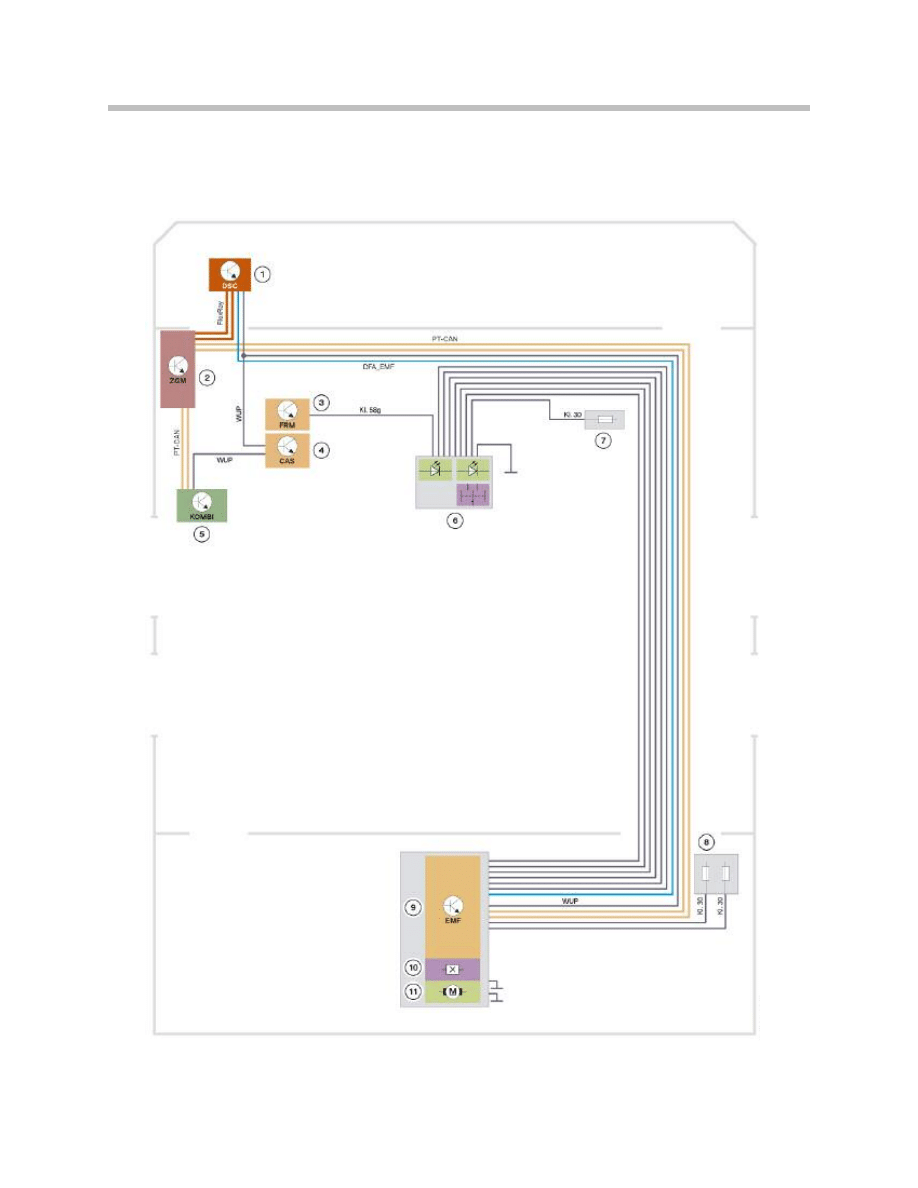
System Circuit Diagram
Electromechanical Parking Brake
60
F01 Longitudinal Dynamics Systems

61
F01 Longitudinal Dynamics Systems
Index
Explanation
1
Dynamic Stability Control
2
Central Gateway Module
3
Footwell module
4
Car Access System
5
Instrument cluster
6
Parking brake button with function indicator and illumination
7
Fuse for parking brake button (front fuse board, junction box electronics)
8
Fuses for EMF electronics and electric motor (rear fuse board in trunk)
9
EMF control unit
10
EMF force sensor
11
EMF electric motor
Document Outline
- Main Menu
- 01_F01 Introduction
- 02_F01 Powertrain
- 03_F01 Voltage Supply & Bus Systems
- 03.1_F01 Bus Systems
- 03.2_F01 Voltage Supply
- 03.3_F01 Energy Management
- 03.4_F01 Car Access System 4
- 04_F01 Chassis Dynamics
- 04.1_F01 Chassis and Suspension
- 04.2_F01 Dynamic Driving Systems
- 04.3_F01 Longitudinal Dynamics Systems
- 04.4_F01 Lateral Dynamics Systems
- 04.5_F01 Vertical Dynamics Systems
- 04.6_F01 Cruise Control Systems
- 05_F01 General Vehicle Electronics
- 05.1_F01 Comfort Access
- 05.2_F01 Central Locking System
- 05.3_F01 Automatic Soft Close
- 05.4_F01 Power Windows
- 05.5_F01 Sliding Tilting Sunroof
- 05.6_F01 Anti-theft System
- 05.7_F01 Automatic Luggage Compartment Lid
- 05.8_F01 Exterior Lighting
- 05.9_F01 Interior Lighting
- 05.10_F01 Wiper-Washer System
- 05.11_F01 Exterior Rear View Mirrors
- 05.12_F01 Seats
- 05.13_F01 Steering Column Switch Cluster
- 06_F01 Driver Information Systems
- 06.1_F01 Displays Indicators and Controls
- 06.2_F01 Head-up Display
- 06.3_F01 BMW Night Vision 2
- 06.4_F01 Active Blind Spot Detection System
- 06.5_F01 KAFAS
- 06.6_F01 PDC-TRSVC
- 07_F01 Information and Communication Technology
- 07.1_F01 Rear Seat Entertainment Systems
- 07.2_F01 Telephone System
- 07.3_F01 Voice Activation System
- 07.4_F01 Audio Systems
- 08_F01 Climate Control
- 09_F01 Passive Safety Systems
- 10_F01 Service Information
- 10.1_F01 System Functions
- 10.2_ISTA-Programming
Wyszukiwarka
Podobne podstrony:
04 4 F01 Lateral Dynamics Systems
04 6 F01 Cruise Control Systems
05 Longitudinal Dynamics Systems
04d E70 Longitudinal Dynamics Systems
04 Liczby ujemne i ułamki w systemie binarnym
04 Płazińce, I rok, I semestr, Systematyka zwierząt, wykłady
Wykład 1 04.02, Studia, Współczesne systemy polityczne
PBO G 04 F01 QSMS document distribution list
04 Linux SYSLOG i logi systemowe
04 Struktury spoleczne. Dynamika struktur, studia, wprowadzenie do socjologii
Systemy polityczne 19.04.10, studia UMK, Systemy ekonomiczne w Europie (W.Kosiedowski)
uproszczone ogloszenie o zamowieniu objetym dynamicznym system zakupow, ZAMÓWIENIA PUBLICZNE 3
bezpieczeństwo jako przedmiot badań, 04 - Bezpieczeństwo Narodowe, Mobilizacja w Systemie Obronnym P
Ekologiczne Systemy Chowu i Żywienia Zwierząt - Wykład 04, WYKŁAD IV- EKOLOGICZNE SYSTEMY CHOWU I ZY
Kontrola w zakresie dynamicznym systemu podwieszenia mostu nad rzeką Suir w Irlandii
04 Liczby ujemne i ułamki w systemie binarnym
04 Płazińce, I rok, I semestr, Systematyka zwierząt, wykłady
Wykład 1 04.02, Studia, Współczesne systemy polityczne
Gorban A N singularities of transition processes in dynamical systems qualitative theory of critica
więcej podobnych podstron