
Initial Print Date: 10/06
Table of Contents
Subject
Page
Longitudinal Dynamics Systems . . . . . . . . . . . . . . . . . . . . . . . . . . . . . . . . . .5
ABS in DSC . . . . . . . . . . . . . . . . . . . . . . . . . . . . . . . . . . . . . . . . . . . . . . . . .5
Dynamic Stability Control (DSC) . . . . . . . . . . . . . . . . . . . . . . . . . . . . . . .6
Electromechanical Parking Brake (EMF) . . . . . . . . . . . . . . . . . . . . . . . .6
Dynamic Cruise Control (DCC) . . . . . . . . . . . . . . . . . . . . . . . . . . . . . . . .6
New Features of the DSC E7x . . . . . . . . . . . . . . . . . . . . . . . . . . . . . . . . . .12
Classic Brake Control Functions . . . . . . . . . . . . . . . . . . . . . . . . . . . . . . . . .13
Additional Brake Control Functions . . . . . . . . . . . . . . . . . . . . . . . . . . . . . .14
Basic Functions of the EMF . . . . . . . . . . . . . . . . . . . . . . . . . . . . . . . . . . .16
Restoring Operation After Emergency Release . . . . . . . . . . . . . . . . .16
Transition from EMF Actuating Unit to DSC . . . . . . . . . . . . . . . . . . . .17
Transition from DSC to EMF Actuating Unit . . . . . . . . . . . . . . . . . . . .18
Function of the Parking Brake Controlled by the DSC Hydraulics . . . .18
Exiting Dynamic Emergency Braking . . . . . . . . . . . . . . . . . . . . . . . . . .19
Fault Distribution Between DSC and EMF Control Unit . . . . . . . . . .20
Fault Regeneration . . . . . . . . . . . . . . . . . . . . . . . . . . . . . . . . . . . . . . . . . .21
Monitoring and Fault Detection . . . . . . . . . . . . . . . . . . . . . . . . . . . . . . .22
System Components. . . . . . . . . . . . . . . . . . . . . . . . . . . . . . . . . . . . . . . . .23
Hydraulic Unit with Add-on Control . . . . . . . . . . . . . . . . . . . . . . . . . . . . .23
Wheel Speed Sensor . . . . . . . . . . . . . . . . . . . . . . . . . . . . . . . . . . . . . . . . . .28
Steering Column Switch Cluster . . . . . . . . . . . . . . . . . . . . . . . . . . . . . . . .30
E70 Longitudinal Dynamics Systems
Revision Date: 11/06

Subject
Page
DSC Sensor . . . . . . . . . . . . . . . . . . . . . . . . . . . . . . . . . . . . . . . . . . . . . . . . . .33
Electromechanical Parking Brake (EMF) . . . . . . . . . . . . . . . . . . . . . . . . . .34
EMF Button . . . . . . . . . . . . . . . . . . . . . . . . . . . . . . . . . . . . . . . . . . . . . . . .34
Emergency Release . . . . . . . . . . . . . . . . . . . . . . . . . . . . . . . . . . . . . . . .35
Using the E70 EMF Emergency Release . . . . . . . . . . . . . . . . . . .36
Electromechanical Actuating Unit . . . . . . . . . . . . . . . . . . . . . . . . . . . .37
EMF Actuating Unit Opened . . . . . . . . . . . . . . . . . . . . . . . . . . . . . .38
Force Sensor . . . . . . . . . . . . . . . . . . . . . . . . . . . . . . . . . . . . . . . . . . . .39
Cruise Control with Brake Intervention (DCC) . . . . . . . . . . . . . . . . . .40
Adjusting the Brake Shoes . . . . . . . . . . . . . . . . . . . . . . . . . . . . . . . . . . . . .42
Removing the Bowden Cable Assemblies . . . . . . . . . . . . . . . . . . . . . . . .42
Start-up . . . . . . . . . . . . . . . . . . . . . . . . . . . . . . . . . . . . . . . . . . . . . . . . . . . . . .43
Initializing the Parking Brake . . . . . . . . . . . . . . . . . . . . . . . . . . . . . . . . . . . .43
Bedding in the Duo-servo Brake . . . . . . . . . . . . . . . . . . . . . . . . . . . . . . . .43
Function on Brake Rolling Dynamometer . . . . . . . . . . . . . . . . . . . . . . . . .44

Subject
Page
BLANK
PAGE

4
E70 Longitudinal Dynamics Systems
Longitudinal Dynamics Systems
Model: E70
Production: From Start of Production
After completion of this module you will be able to:
• Understand the integration of ABS, DSC, EMF and DCC in Longitudinal
Dynamics System.
• Describe the operation of Longitudinal Dynamics System.
• Identify the components that operate Longitudinal Dynamics System.

Longitudinal Dynamics Systems
By applying today's standard consideration aspects, subdividing the functions of driving
dynamics systems into the three co-ordinate axes results in the use of three different
systems that belong to longitudinal dynamics on the E70.
Longitudinal dynamics systems (effective direction mainly on the x-axis or longitudinal
axis):
•
(ABS) Anti-lock braking system
•
(DSC) Dynamic stability control
•
(EMF) Electromechanical parking brake
•
(DCC) Dynamic cruise control (cruise control with brake intervention)
ABS in DSC
The ABS prevents the wheels locking while braking and therefore ensures that the vehi-
cle stays on track and can be steered in critical situations.
ABS is constantly activated during vehicle operation and cannot be switched off by the
driver. The four wheel speed sensors send data to the DSC control unit that monitors the
speed of each wheel. If one or several wheels decelerate at a faster rate than permitted,
the DSC control unit activates the hydraulic unit, which in turn reduces the hydraulic
pressure in the corresponding brake line. The DSC control unit and the hydraulic unit
make up one assembly.
When the DSC control unit requests intervention of the antilock braking system, it acti-
vates the inlet and outlet solenoid valves in the hydraulic unit of the affected brake line
and switches on the return pump. The inlet valve closes in order to disconnect the brake
line(s) from the master brake cylinder and the outlet valve opens to allow the brake fluid
of the affected brake circuit to escape into the reservoir in order to reduce the pressure in
the circuit. Consequently, the braking effect is reduced and the wheel begins to turn.
The DSC control unit then opens and closes the inlet and outlet valves in such a way as
to ensure the optimum braking pressure is built up at each wheel without the wheels
locking. The return pump conveys brake fluid from the equalizing reservoir of the master
brake cylinder, thus maintaining a constant brake fluid pressure downstream of the inlet
valves so that the pressure in the brake lines is immediately re-established when the inlet
valves are open again.
In the case of braking with ABS assistance, the driver normally obtains feedback in the
form of pedal vibration and the noise of solenoid valves or the pump. This is reduced to a
minimum by the high-performance hydraulic unit of the DSC E7x in the E70.
5
E70 Longitudinal Dynamics Systems
Introduction

Dynamic Stability Control (DSC)
The E70 is equipped with a new generation of the dynamic stability control system.
Note: To date, the DSC driving dynamics system on all-wheel drive vehicles
was referred to with the abbreviation "DXC".
Since this lead to confusion with the xDrive, in the future the dynamic stability control sys-
tem will be known as DSC also on all-wheel drive vehicles.
This new generation of the dynamic stability control (DSC E7x, supplied by Bosch) in the
BMW X5 is actually the only driving dynamics system that covers all three areas of longi-
tudinal, transverse and vertical dynamics with its control intervention functions and its
modular functional structure.
With its varied control strategies, the DSC ensures outstanding driving stability within
physical limits, active safety and excellent traction in all driving situations.
Electromechanical Parking Brake (EMF)
The electromechanical parking brake was used for the first time at BMW on the E65 (7
Series).
In principle, the task of the parking brake is to secure the stationary vehicle to prevent it
rolling away. The parking brake firmly holds the parked vehicle. In contrast to the parking
brake that to date was based on a pure mechanical hand brake and foot brake system,
the EMF is designed as an automated, comfort-oriented parking brake system where the
driver can apply and release the parking brake by the push of a button.
The design layout of the parking brake system is in keeping with typical BMW require-
ments:
• Exclusion of all safety-critical situations
• Optimum functionality
• Maximum system availability
• High degree of comfort and convenience
Besides complying with the legal requirement of mechanically holding the parked vehicle
and providing an independently operable parking brake in addition to the service brake,
one of the main advantages of the EMF is that it enables dynamic braking with DSC con-
trol.
Dynamic Cruise Control (DCC)
The dynamic cruise control is a conventional cruise control system (Tempomat) which
features additional functions including active brake intervention. Cruise control with brake
intervention (DCC) was introduced for the first time at BMW on the E90 (3 Series).
6
E70 Longitudinal Dynamics Systems
7
E70 Longitudinal Dynamics Systems
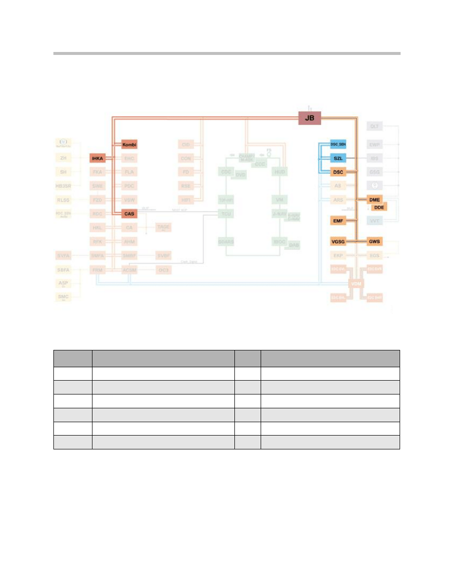
DSC Bus Overview
Index
Explanation
Index
Explanation
KOMBI
Instrument cluster
DSC
Dynamic stability control
IHKA
Automatic climate control
DME
Digital motor electronics
CAS
Car Access System
EMF
Electromechanical parking brake
JB
Junction box
VGSG
Transfer box control unit
DSC_SEN
DSC sensor
GWS
Gear selector lever
SZL
Steering column switch cluster
8
E70 Longitudinal Dynamics Systems
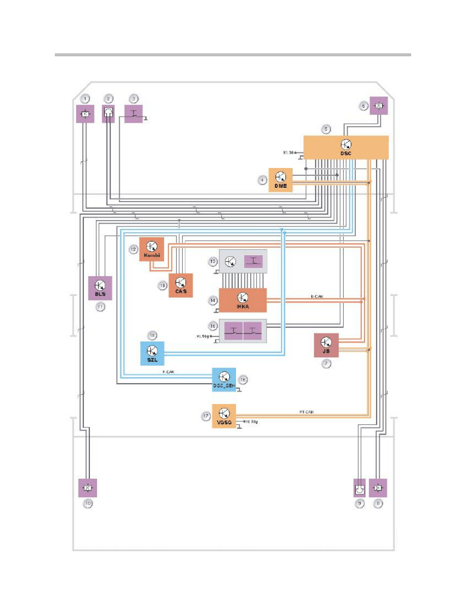
DSC Circuit Diagram
Legend for DSC Circuit Diagram
DSC System Overview
9
E70 Longitudinal Dynamics Systems
Index
Explanation
Index
Explanation
1
Wheel-speed sensor, front left
11
Brake light switch
2
Brake pad wear indicator, front left
12
Instrument cluster
3
Brake fluid level sensor
13
Center console switch cluster
4
Digital motor electronics
14
Automatic climate control
5
Dynamic stability control
15
Gear selector lever
6
Wheel-speed sensor, front right
16
DSC sensor
7
Junction-box ECU
17
Transfer box control unit
8
Wheel-speed sensor, rear right
18
Steering column switch cluster
9
Brake pad wear indicator, rear right
19
Car Access System
10
Wheel speed sensor, rear left
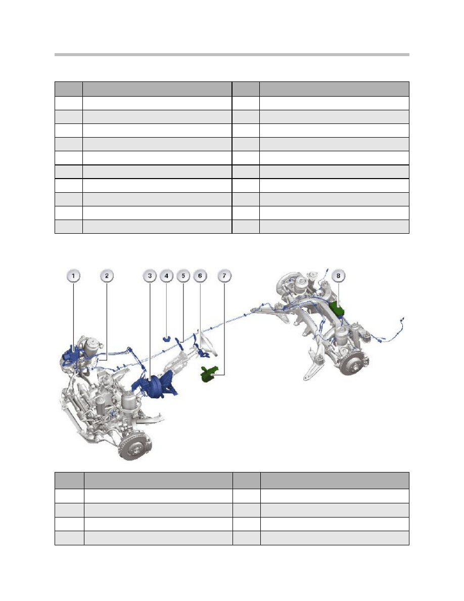
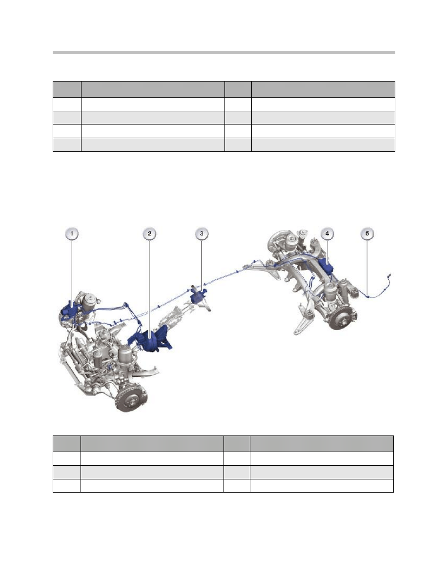
Index
Explanation
Index
Explanation
1
Hydraulic unit with DSC control unit
5
Center console switch cluster
2
Wheel speed sensor (4x)
6
Steering column switch cluster
3
Master brake cylinder
7
Gear selector lever
4
DSC sensor
8
EMF actuating unit
10
E70 Longitudinal Dynamics Systems
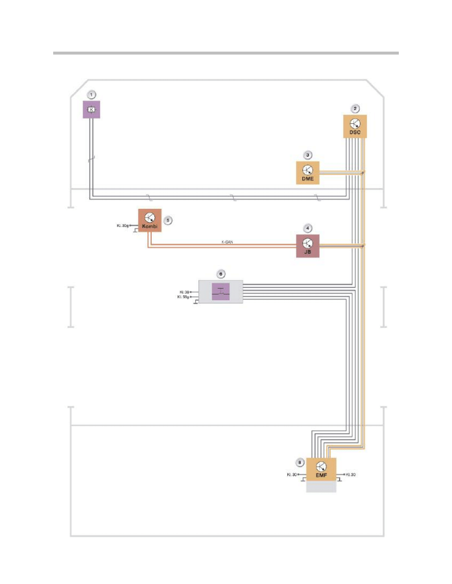
EMF Schematic Circuit Diagram
Legend for EMF Schematic Circuit Diagram
EMF System Overview
11
E70 Longitudinal Dynamics Systems
Index
Explanation
Index
Explanation
1
Wheel-speed sensor, front left
5
Instrument cluster
2
Dynamic stability control
6
Gear selector lever
3
Digital motor electronics
7
EMF actuating unit
4
Junction-box ECU
Index
Explanation
Index
Explanation
1
Dynamic stability control
4
EMF actuating unit
2
Master brake cylinder
5
Emergency release EMF
3
Gear selector lever

New Features of the DSC E7x
The system supplier for the DSC E7x is Bosch. With its optimized control functions, the
new system design makes a significant contribution to increased driving dynamics.
Additional functions for active safety and additional comfort have been implemented in
the new system. The new system in the E70 offers the following advantages:
• Driving Dynamics
– DSC mode: Increased driving dynamics and maximum traction. Thanks to more
precise and faster control interventions, the driver can further extend the bound-
aries of driving dynamics while retaining vehicle safety.
– DTC mode: Compared to DSC mode, Dynamic Traction Control (DTC) allows for
increased slip at the drive wheels to provide maximum propulsion when driving off
in snow for instance. In addition, the stabilizing control interventions cut in later in
DTC mode thus allowing a more sport-oriented driving profile.
• Active Safety
– The additional functions of brake standby, dry braking and fading assistance short-
en the stopping distances.
– Increased DSC efficiency makes for more effective safety-relevant functions.
• Comfort
– Improved operating comfort (brake interventions are less audible, pedal vibration is
drastically reduced) through the use of a 6-piston pump in connection with a new
higher-frequency electrical actuation system.
– Additional functions such as start-off assistant and parking brake provide increased
driver assistance and comfort.
12
E70 Longitudinal Dynamics Systems

Classic Brake Control Functions
• Antilock Braking System (ABS)
ABS prevents individual wheels from locking while braking by targeted modulation of
the braking pressures. The steerability of the vehicle through the front wheels is
largely retained. When braking on road surfaces with different coefficients of friction,
the straight-ahead position is stabilized in co-operation with the active steering
(option).
• Cornering Brake Control (CBC)
(CBC) keeps the vehicle under control when braking lightly in fast corners by asym-
metric control of the braking pressure, thus improving the cornering stability.
• Automatic Stability Control (ASC)
(ASC) prevents spinning of the drive wheels by way of specific brake application and
influencing the drive torque delivered by the combustion engine thus optimizing the
forward propulsion of the vehicle.
• Dynamic Brake Control (DBC)
If an emergency braking operation is initiated by the driver, the system assists the
driver by automatically applying the maximum braking pressure immediately in order
to optimize the braking effect.
• Automatic Differential Brake (ADB-X)
ADB-X replicates the function of the differential locks: if a wheel tends towards spin-
ning, it is automatically braked so that forward propulsion can still be achieved
through the other wheel on the axle.
• Dynamic Stability Control (DSC)
A vehicle which tends to understeer or oversteer is stabilized by specific brake inter-
vention on individual wheels. This function operates on the E70 together with the
active steering (option).
• Hill Descent Control (HDC)
HDC automatically applies the brakes at individual wheels when driving downhill at
low speed, particularly on poor surfaces such as sand, gravel or snow. The function
is activated by means of a button in the center console.
• Trailer Stabilization Logic
This function automatically detects when a vehicle with a trailer begins to sway and it
stabilizes the vehicle-trailer combination by specific brake intervention thus reducing
the speed to below the critical shear/swerve level.
13
E70 Longitudinal Dynamics Systems

Additional Brake Control Functions
• Dynamic Traction Control (DTC)
DTC represents a special mode of DSC which, while interacting with (ASC), (ADB-X)
and xDrive, realizes maximum propulsion on loose surfaces such as snow, sand or
gravel, by extending the slip thresholds. The stabilization interventions in connection
with DTC cut in later than with DSC thus enabling a more sport-oriented driving pro-
file.
• Brake Standby
This function builds up a moderate braking pressure in the system when the driver
very quickly takes his/her foot off the accelerator pedal. The braking effect then cuts
in faster to assist the driver in emergency braking.
• Dry Braking
This function lightly applies the brake pads at specific intervals depending on the
operation of the windscreen wiper in order to dry the brake discs. This distinctly
improves the braking effect in braking operations.
• Fading Assistance
This function assists the driver in applying the braking force when the brake temper-
ature is very high due to an extreme driving profile which requires a higher braking
force in order to achieve the required braking effect.
• Start-off Assistant
The start-off assistant holds the vehicle on gradients for about. 1.5 seconds after
the driver has taken his/her foot from the brake. In this way, the driver can conve-
niently operate the accelerator pedal without the vehicle rolling back.
• Electromechanical Parking Brake (EMF)
The EMF is a parking brake that can be applied and released by means of a bidirec-
tional button. Depending on the respective vehicle operating situation, the holding
force is applied wither hydraulically via the DSC or mechanically via EMF.
14
E70 Longitudinal Dynamics Systems
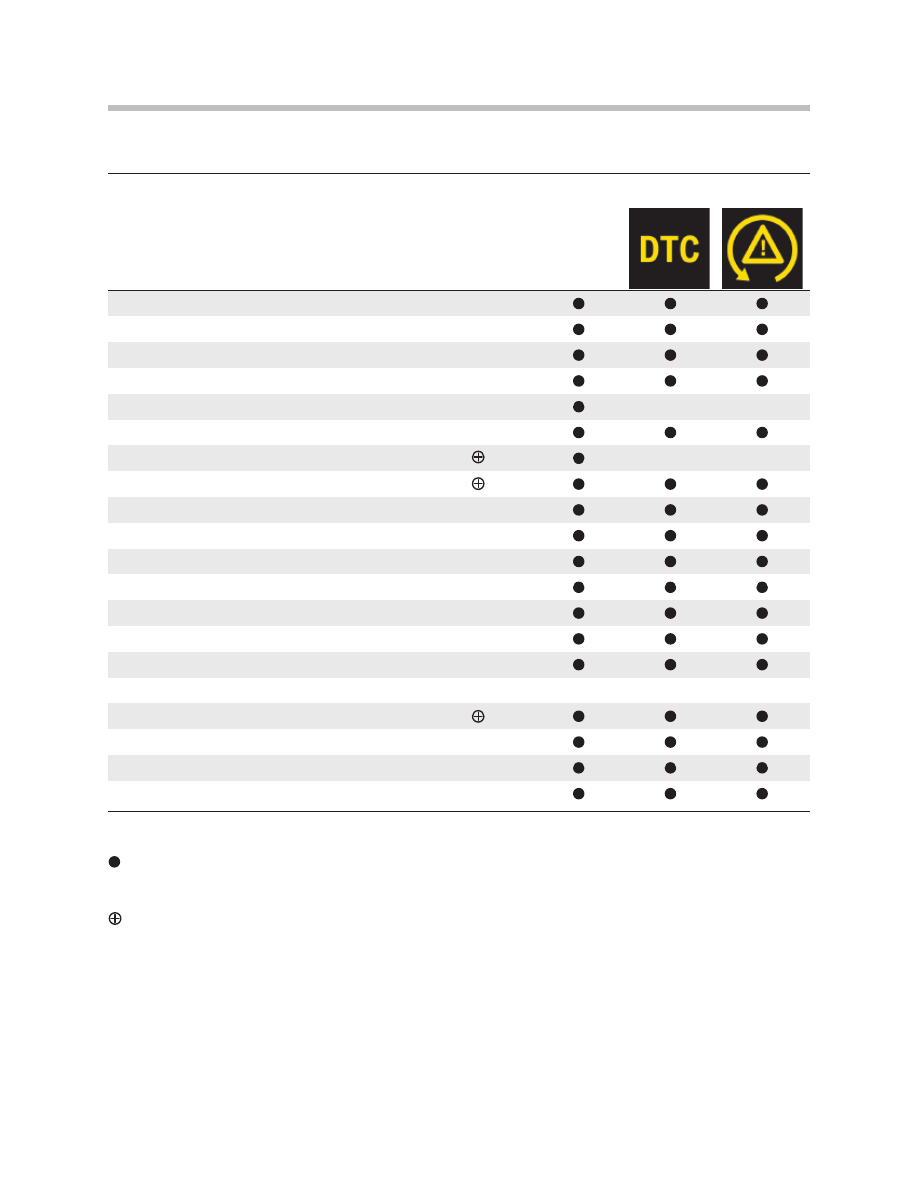
Symbols:
= System active
X = System with elevated control thresholds
= Can be switched on/off
e
b
n
a
C
n
o
i
t
c
n
u
F
switched
on/off by
driver
DSC ON
DTC
DSC OFF
ABS
EBV
CBC
MSR
ASC
X
ADB-X
DSC
X
HDC
Dry braking
Start assist
Braking readiness
Fading assistance
DBC
- DBS
- MBS
EMF [parking brake]
GRR+ (included in active steering option)
RPA
CBS
DSC Functions
15
E70 Longitudinal Dynamics Systems

The parking brake (EMF) has two different functions, depending on the operating status
of the vehicle.
• Parking brake mode
– When the engine is running or the vehicle is rolling, the parking brake acts on the
service brake with the aid of the DSC hydraulics. This means the brake units on the
front and rear axle are active.
– If the engine is not running and the vehicle is stationary, the electromechanical
actuator and its cable assembly ensure the parking brake acts on the duo-servo
drum brake on the rear axle. In this case, the vehicle is braked as defined in the con-
trol unit.
• Dynamic braking
Defined retardation is triggered via the DSC system if the parking brake button is
pulled up while driving. The retardation or deceleration is monitored by the DSC
control functions and takes place for as long as the parking brake button is pulled.
Emergency Release
A mechanical emergency release facility is provided in order to be able to release the
parking brake in the event of the electromechanical actuating unit failing or insufficient
power supply.
Secure vehicle to prevent it rolling before operating
the emergency release!
The release procedure is performed manually with the emergency release cable assem-
bly and the emergency release handle from the vehicle tool kit. The emergency release
procedure releases the duo-servo drum brake by way of mechanical intervention in the
actuator of the electromechanical control unit.
Note: After a power failure, it may still not be possible to move the vehicle even
after releasing the brake with the emergency release facility. The park-
ing lock of the automatic gearbox may still be engaged (see Product
Information Automatic Gearbox E70).
Once released, using the emergency release facility, the parking brake cannot be reacti-
vated manually. The function can be restored only by way of electrical activation.
Restoring Operation After Emergency Release
After turning on the ignition, push down the EMF operating button and pull up again to
activate the parking brake.
Basic Functions of the EMF
16
E70 Longitudinal Dynamics Systems
CAUTION!!!

Service Functions
After replacing the brake shoes of the duo servo drum brake as part of repair or mainte-
nance procedures, the new brake shoes must be bedded-in to ensure adequate holding
effect of the new brake shoes. The software of the EMF control unit features a "bedding-
in" service mode that must be activated in this case with the BMW diagnostic system.
Indicator/warning lamps in the instrument cluster signal the operating status as well as
system fault situations. In the event of faulty signals, the system causing the problem
enters corresponding fault codes in the control unit and the system is partially or totally
shut down corresponding to the situation. The driver receives additional information on
any restricted functions in the control display.
Note: It is only possible to coast or push the vehicle with the transmission in
position N. Neutral usually remains selected for a maximum of 30 min-
utes. If the vehicle is stationary for longer, the automatic transmission
parking lock will automatically be engaged.
Example Scenarios
Basic function of the parking brake controlled by the actuating unit Scenario: "Ignition
ON", the engine is not yet running and the foot brake is pressed.
With the vehicle stationary, the parking brake is released or applied by pulling or pressing
the EMF button. The indicator lamp in the instrument cluster either goes out or lights up
red.
Note: The parking brake can be released only with the foot brake pressed when
the engine is running or turned off.
The dynamic braking function is triggered if the EMF operating button is pulled while the
vehicle is rolling.
Transition from EMF Actuating Unit to DSC
The system switches over from mechanical to hydraulic mode when the engine is start-
ed. If the EMF actuating unit was applied at the time, the DSC hydraulics will assume
control of the braking force. The EMF actuating unit is not released until the hydraulics
are holding the vehicle secure. The indicator lamp remains lit red throughout this process,
and the driver is unaware of the transition (the lamp does not even flash).
17
E70 Longitudinal Dynamics Systems

Transition from DSC to EMF Actuating Unit
The transition to the EMF actuating unit always takes place on exiting the hydraulic func-
tion at "ignition OFF". If the parking brake was applied, the hydraulics are not released
until the EMF actuating unit is applied. The indicator lamp remains red throughout this
transition.
Function of the Parking Brake Controlled by the DSC Hydraulics
Scenario: "Engine running"
The parking brake is applied or released completely by hydraulic means when the EMF
operating button is pulled or pressed.
Dynamic braking ( hydraulic) is triggered with the vehicle rolling and the button operated
at v >3 km/h. The basic functions mainly correspond to the functional scope of a conven-
tional mechanical parking brake.
The system switches between "brake applied" and "brake released" with pressure build-
up and pressure reduction every time the EMF button is pulled or pressed.
The parking brake must be released by pressing the EMF button before starting off.
Pulling away against the applied brake pressure results in an increase in pressure and a
warning to the driver.
Scenario: "At rest"
Remove control removed The parking brake enters rest status when the remote control is
removed. If the parking brake is applied, the time-delayed red indicator lamp signals this
status to the driver.
If the EMF actuating unit is released in rest mode, the EMF actuating unit is applied
when the EMF button is pulled with the vehicle stationary. If the vehicle is in motion,
pressing the button will initiate dynamic braking.
Note: Always take the remote control with you when leaving the vehicle
otherwise children could release the parking brake.
Dynamic Braking
Two braking units for brake operation are required by law (previously: foot brake and hand
brake) In the E70, the second operating point besides the foot brake is the EMF button
on the gear selector lever.
The vehicle is braked by the drum brakes at the rear axle if the EMF button is pressed
and held at speeds below v = 3 km/h and with the engine switched off.
The vehicle is braked at a rate of 3 m/s2 for 0.8 seconds if the EMF button is pressed
when the vehicle is in motion. Braking power is then ramped up to 5 m/s2 for the next 2
seconds. This braking action is retained for as long as the EMF button is pulled.
18
E70 Longitudinal Dynamics Systems

For stability reasons (over-braking - rear axle) the dynamic braking function is also trig-
gered in the rest state in response to the vehicle rolling (engine turned off, ignition OFF)
by means of active pressure build-up by the DSC hydraulics together with the DSC func-
tion. The brake pressure required is made available as rapidly as possible.
The braking action is always monitored by the DSC control function. This ensures vehicle
stability while braking. Since all four wheels are braked hydraulically, there is considerably
greater deceleration with a minimum of operating effort (EMF button) by comparison with
conventional parking brakes. The controlled brakes are therefore able to contribute to
improving vehicle safety.
For traffic safety reasons, operation of dynamic braking is indicated to the road users
behind by the brake lights coming on.
To avoid accidental operation and misuse, the driver is notified of dynamic braking opera-
tion by a display message and gong.
This function is intended only for use in an emergency and must never be used as a sub-
stitute for normal operation of the service brake.
The more effective braking solution is used if the parking brake deceleration request is
overlapped by the brake pedal being depressed. The DSC control unit decides which
deceleration request is to be carried out.
Exiting Dynamic Emergency Braking
The vehicle will remain hydraulically braked even after the EMF button has been released
if the vehicle is braked to a halt by dynamic braking. There is a transition to the normal
DSC hydraulics function. The hydraulic brake is only released when the EMF button is
pressed once more.
If the EMF button is pressed while the vehicle is still in motion, the system level prevailing
before the emergency dynamic braking was activated is resumed. If the parking brake is
released and the vehicle is coasting, it is possible to activate emergency dynamic braking
in any situation (terminal 30, 15, R) by pressing the EMF button.
19
E70 Longitudinal Dynamics Systems

Error Messages
All fault statuses are detected by the monitoring system and displayed to the driver. The
main aim is to avoid safety-critical conditions for vehicle occupants, the vehicle and its
surroundings.
A fault can be assigned different priorities depending on the driving situation (vehicle sta-
tionary/in motion, starting/stopping) and the system availability. In addition to the indicator
lamp, supplementary instructions may be shown in the control display.
To avoid additional damage, faults in the parking brake mechanism, particularly a broken
cable in the operating cable assembly and excess load are detected by the force sensor
and indicated accordingly. See shutdown strategy table.
Error messages can no longer be output actively in the event of the EMF control unit fail-
ing. In this case, the instrument cluster assumes the control of the correct error message
on recognizing the absence of the regular EMF telegram via the PT-CAN (alive signal).
General Parking Brake Fault Concept
Fault Distribution Between DSC and EMF Control Unit
Only DSC faults that actually affect operation of the parking brake result in shut-down of
the hydraulic function. These are mainly faults that result in shut-down of the ABS func-
tionality.They trigger the transition to manual emergency mode. Dynamic braking is no
longer possible unless only CAN faults occur affecting this functionality.
20
E70 Longitudinal Dynamics Systems
Shut-down Strategy
Fault
Availability
Back-up System
Parking brake
(mechanical)
v = 0
Dynamic braking
(hydraulic)
v > 0
CAN signal
OK
OK
DSC
hydraulics
OK
NA
Service brake +
hand brake
Actuating
mechanism
NA
OK
Park position auto-
matic gearbox
EMF control
unit
NA
NA
Park position auto-
matic gearbox and
service brake and
auxiliary brake if
necessary

• Shut-down level "electromechanical mode"
(only EMF actuating unit) initiated by following DSC faults
– DSC control unit fault
– Electrical fault (e.g. wiring harness)
– Sensor fault (brake light switch/wheel speed)
– actuator fault/hydraulic unit
– Bus communication fault
• Shut-down level "electrohydraulic mode"
(failure of EMF actuating unit)
– Force sensor fault
– Actuator fault of EMF actuating unit
– Error in actuation electronics
– Fault in actuating mechanism
– Electrical fault
• Shut-down level "total shut-down"
– EMF control unit or controller fault
– EMF button fault
– Electrical fault, power supply
Note: All fault codes are stored in the control unit in which the monitoring rou-
tine was performed. The EMF control unit is informed of the fault status
of the DSC control unit and vice versa.
Fault Regeneration
When a fault is detected, the system remains in a safe mode until the end of the
"ignition ON" cycle, once reached, a shut-down level is not cancelled during the cycle.
21
E70 Longitudinal Dynamics Systems

A shut-down status can only be cancelled when a corresponding check beforehand
guarantees that the component previously detected as faulty is functioning correctly.
For this reason, such component tests are also performed in shut-down mode. The fault
information is retained in the fault code memory. The shut-down status is then cancelled
when a new "ignition ON" cycle is started.
If correct operation of the component cannot be determined after a fault, the parking
brake will remain in the secure, shut-down state until the next workshop visit where the
fault code can be deleted by the diagnostic unit after a repair.
Monitoring and Fault Detection
• Monitoring of electrical faults:
Breaks (open circuits) and short-circuits with respect to ground and U-batt of all
cables leading to the control unit as well as short-circuits in the actuator or its cables
are detected and dealt with accordingly. If possible, this also applies to short-circuits
of neighboring connector pins.
External breaks or short-circuits do not result in irreparable damage to the control unit.
• Monitoring input signals:
All input variables of the parking brake are monitored. In the event of a fault occur-
ring, the complete system is shut down with a corresponding error message and
fault code entry.
• Monitoring EMF button:
The EMF button has a redundant layout for diagnosis. The signal levels of this com-
ponent are permanently monitored. In the event of a plausibility error, the complete
system is shut down with a corresponding fault code entry.
The DSC control unit also checks the plausibility of the signals from the EMF button.
Signal level errors result in a corresponding fault code entry with partial shut-down.
Dynamic braking is now no longer possible.
• Monitoring vehicle speed signals:
The parking brake system is totally shut down only when all 3 speed inputs have
failed or are not available
– The direct digital wheel speed signal, also known as the discrete speed signal, is
permanently checked in terms of plausible signal edge change.
– A mutual plausibility check of the reference speed made available from the DSC
via the PT-CAN and the discrete speed signal is constantly performed.
– The reference speed is the mean wheel speed from the DSC which is compared
with the transmission output speed sent by the EGS.
22
E70 Longitudinal Dynamics Systems
Hydraulic Unit with Add-on Control
With its new pump concept, the hydraulic unit provides a significant improvement in
control accuracy. 2 x 3 pump elements with a diameter of 6.5mm and intake-optimized
units operate in the hydraulic unit. This pump concept ensures substantially improved
pressure dynamics resulting in lower pedal feedback in ABS mode and higher control
quality in HDS.
For the driver this is noticeable in as far as the pedal pulsation can now only be felt very
slightly during ABS braking. There is a pressure sensor in the hydraulic unit.
DSC Control Unit
The DSC control unit can be replaced individually. The 47-pin connector connects the
DSC control unit to the engine wiring harness.
23
E70 Longitudinal Dynamics Systems
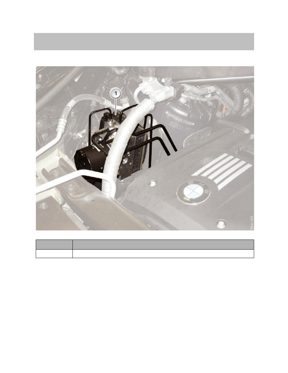
System Components.
Index
Explanation
1
Hydraulic unit with DSC control unit
24
E70 Longitudinal Dynamics Systems
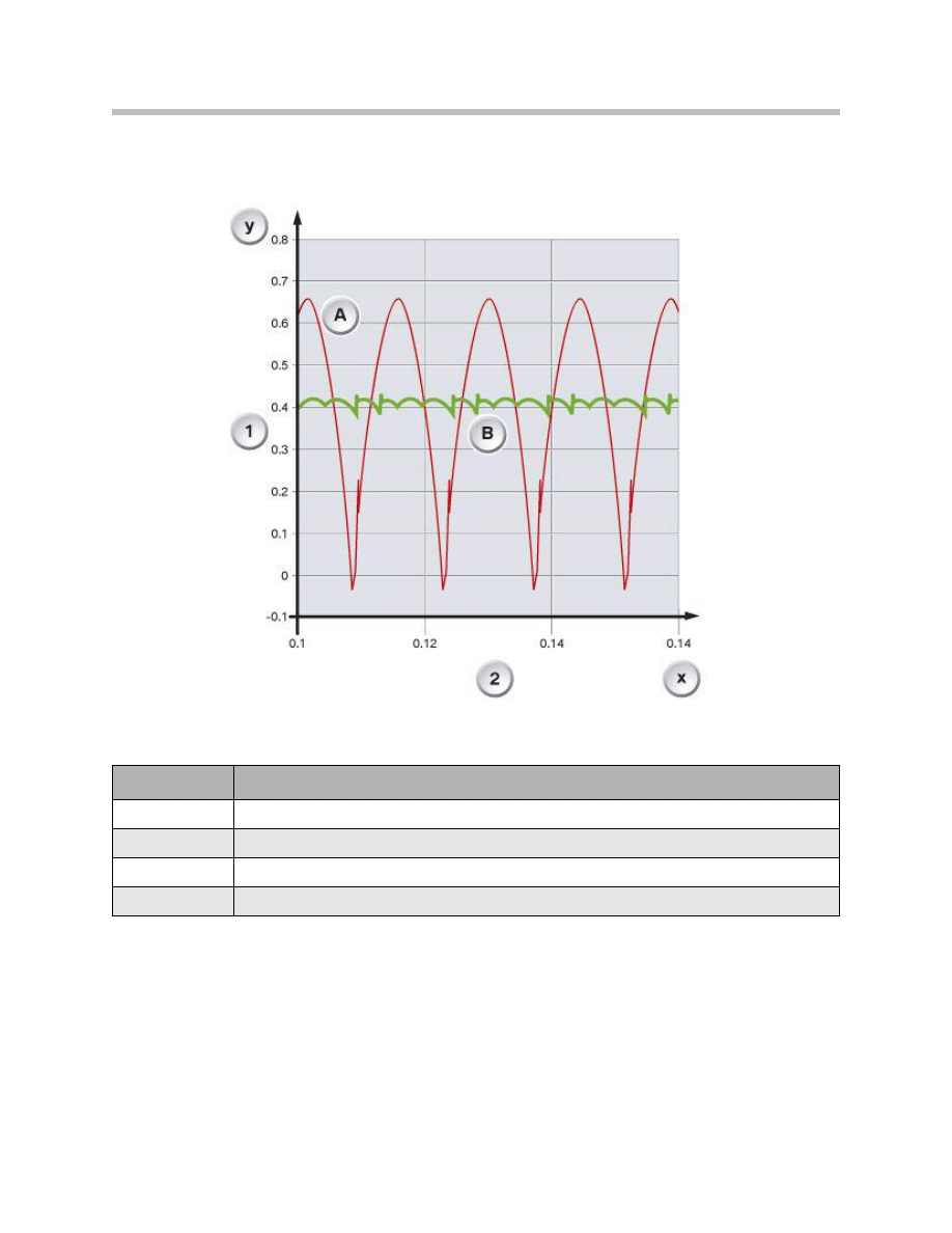
Volumetric Flow of Hydraulic Unit
Index
Explanation
1
Q [l/min] Liters per minute
2
t [s] at Qmean = constant
A
DSC8
B
DSC E7x

25
E70 Longitudinal Dynamics Systems
NOTES
PAGE
26
E70 Longitudinal Dynamics Systems
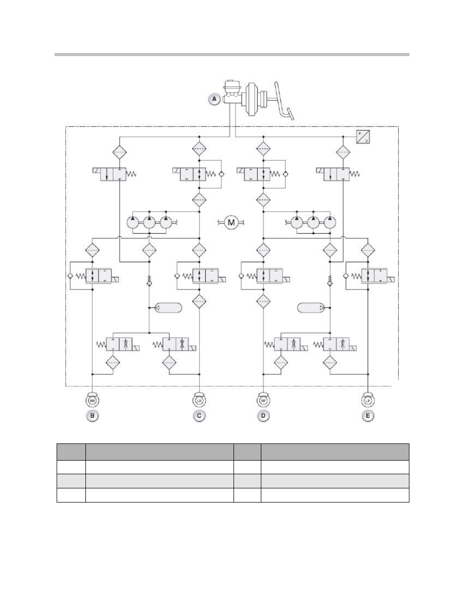
Hydraulic Diagram DSC E70
Index
Explanation
Index
Explanation
A
Master brake cylinder
D
Front right brake
B
Rear right brake
E
Front left brake
C
Rear left brake
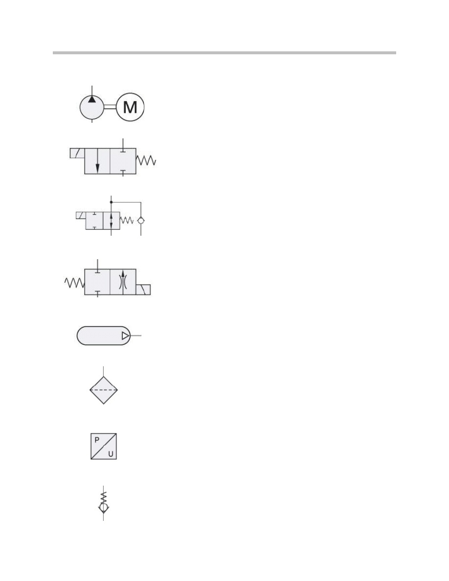
Legend for Hydraulic Symbols
27
E70 Longitudinal Dynamics Systems
Electrically operated
hydraulic pump
Filter
2/2-way valve
Pressure sensor
2/2-way valve with
non-return valve
Non-return valve
Outlet valve
Hydraulic accumulator
Wheel Speed Sensor
4 active wheel speed sensors are installed in the E70. All 4 sensors have a direct hard-
wired connection to the DSC control unit.
These active wheel speed sensors facilitate recognition of the direction of rotation, air
gap (clearance) and standstill. The DSC control unit receives this information in the form
of a PWM signal.
Main Features of the Active Wheel Speed Sensor
• Location recognition:
Indicates whether the change in magnetic field strength can be guaranteed for cor-
rect operation with a high degree of certainty. This signal is no longer required after
approximately 20 km/h / 12 mph.
• Stationary recognition:
The power supply is switched on if the wheel is stationary for more than 1 second.
A signal is sent to the DSC control unit every 740ms so that the availability of the
sensor can be checked.
• Speed signal:
This is a frequency-dependent signal for determining the speed of the wheel.
• Direction of rotation recognition:
Indicates the direction of rotation, clockwise / counterclockwise.
• Air gap reserve:
Indicates whether the change in magnetic field strength is below the
necessary value for correct operation.
28
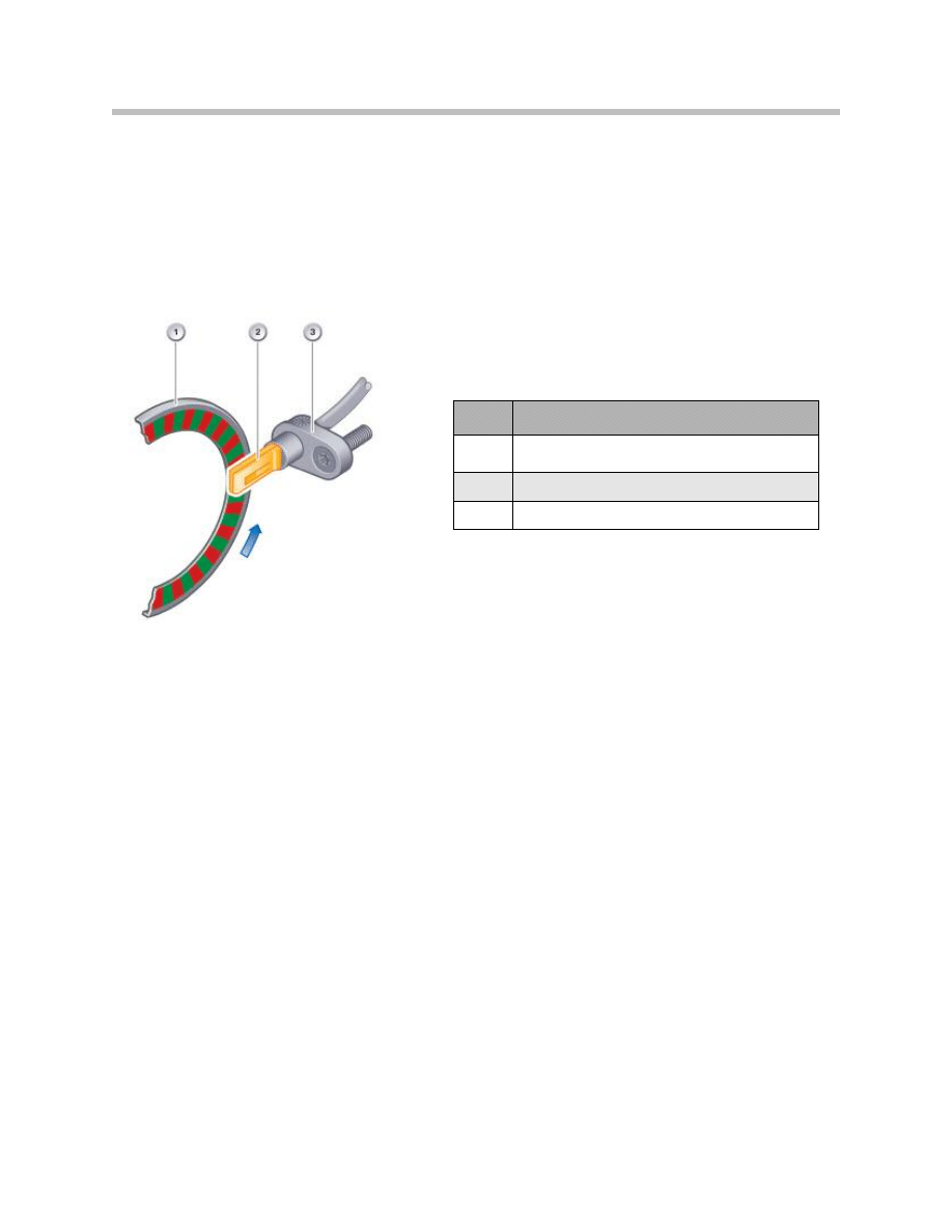
E70 Longitudinal Dynamics Systems
Index
Explanation
1
Sensor ring/ferromagnetic wheel
bearing seal carrier
2
IC sensor with Hall sensor
3
Sensor housing
A two-wire line is used to transfer the signal.This two-wire interface is a combined earth
and data line.
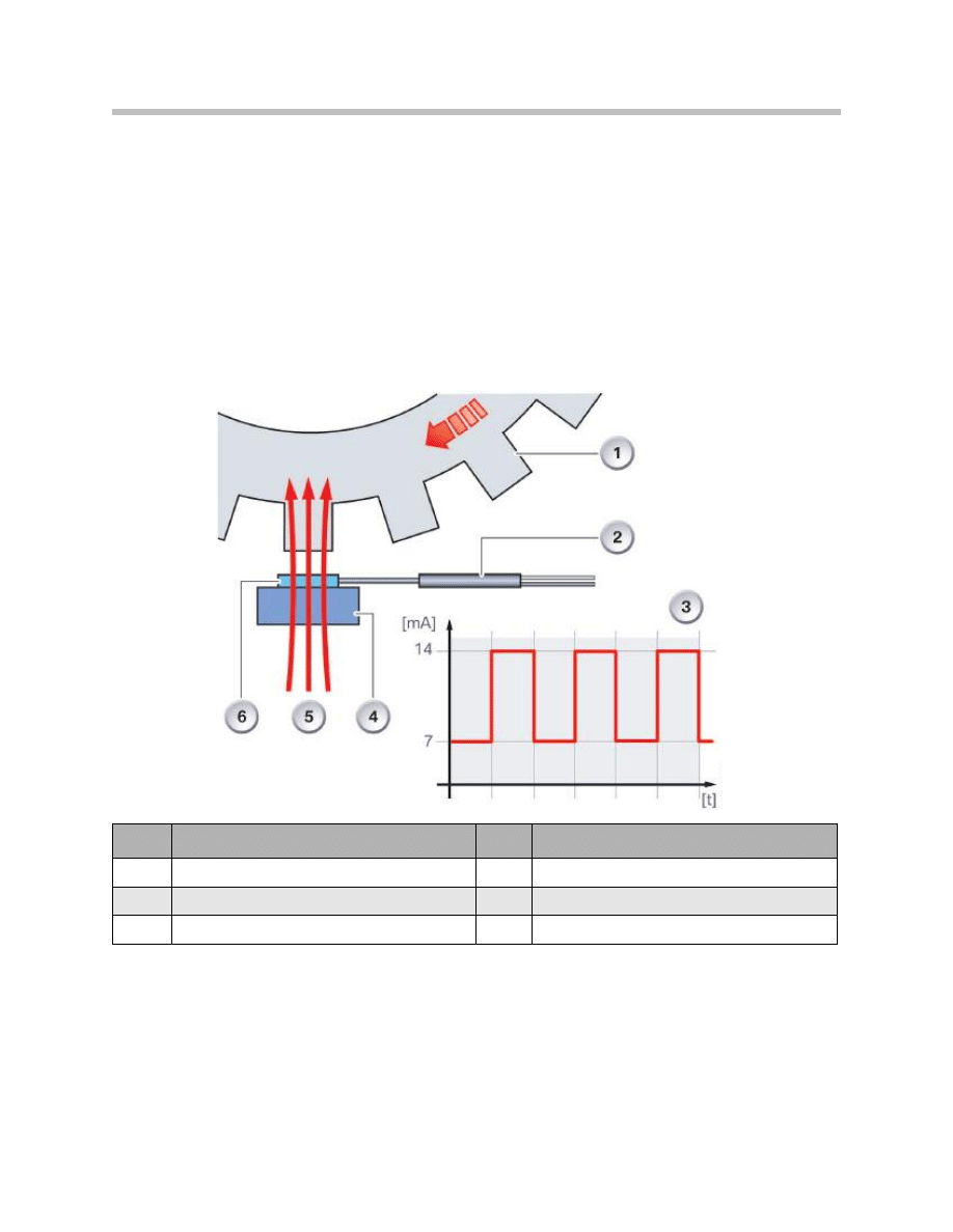
The permanent magnet in the wheel speed sensor generates a magnetic field. The lines
of the magnetic field run perpendicular to the sensor layer on the sensor element.
The deviation of the fields lines caused by the increment wheel produces changes in
resistance in the thin ferromagnetic layer of the sensor element.
29
E70 Longitudinal Dynamics Systems
Index
Explanation
Index
Explanation
1
Increment wheel
4
Permanent magnet
2
Electronic evaluation unit
5
Magnetic field lines
3
Signals from the wheel speed sensor
6
Sensor element
Function of Active Wheel Speed Sensor
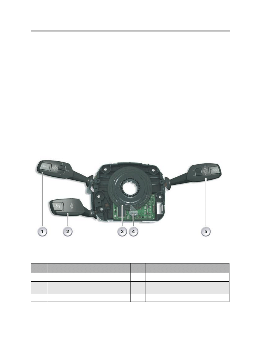
Steering Column Switch Cluster
The Steering Column Switch Cluster (SZL) consists of the following components:
• SZL electronics
• Steering angle sensor
• Steering column stalk, cruise control
• Steering column stalk, direction indicator
• Steering column stalk, wiper
• Coil spring assembly
The steering column switch cluster can only be replaced as a complete unit. The coil
spring assembly is fitted on the steering column switch cluster. The spring coil assembly
can be removed and replaced individually.
30
E70 Longitudinal Dynamics Systems
Index
Explanation
Index
Explanation
1
Steering column stalk, direction indicator
4
Steering column switch cluster with optical senor
2
Steering column stalk, cruise control
5
Steering column wiper stalk with buttons for
rain/driving light/solar sensor
3
Code disc
SZL Electronics
The SZL electronics consists of a processor, the power supply and following interfaces:
• F-CAN
• Optical switches
• Electrical switches
The optical sensor for measuring the steering angle is integrated in the pc-board of the
control unit.
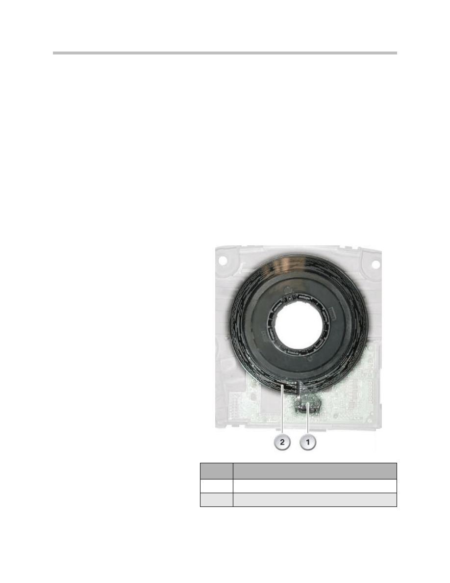
Steering Angle Sensor
The steering angle sensor is designed as a contactless, optical angle measuring system.
The system consists of a code disc and an optical sensor. The code disc is connected by
means of a driver to the steering wheel. The code disc turns within the optical sensor as
the steering wheel is turned.
Code Disc
The code disc is black and features a
line pattern. This pattern consists of
two continuous lines on the outside
and inside of the code disc.
There are broken lines located at
defined intervals between the two
continuous lines. These lines repre-
sent the digital area of the sensor.
The digital code changes every 2°.
The oblique lines in the outer zone
represent the analogue area of the
sensor. These lines permit precise
measurement (0.1°) of the steering
angle.
31
E70 Longitudinal Dynamics Systems
Index
Explanation
1
Optical sensor
2
Code disc
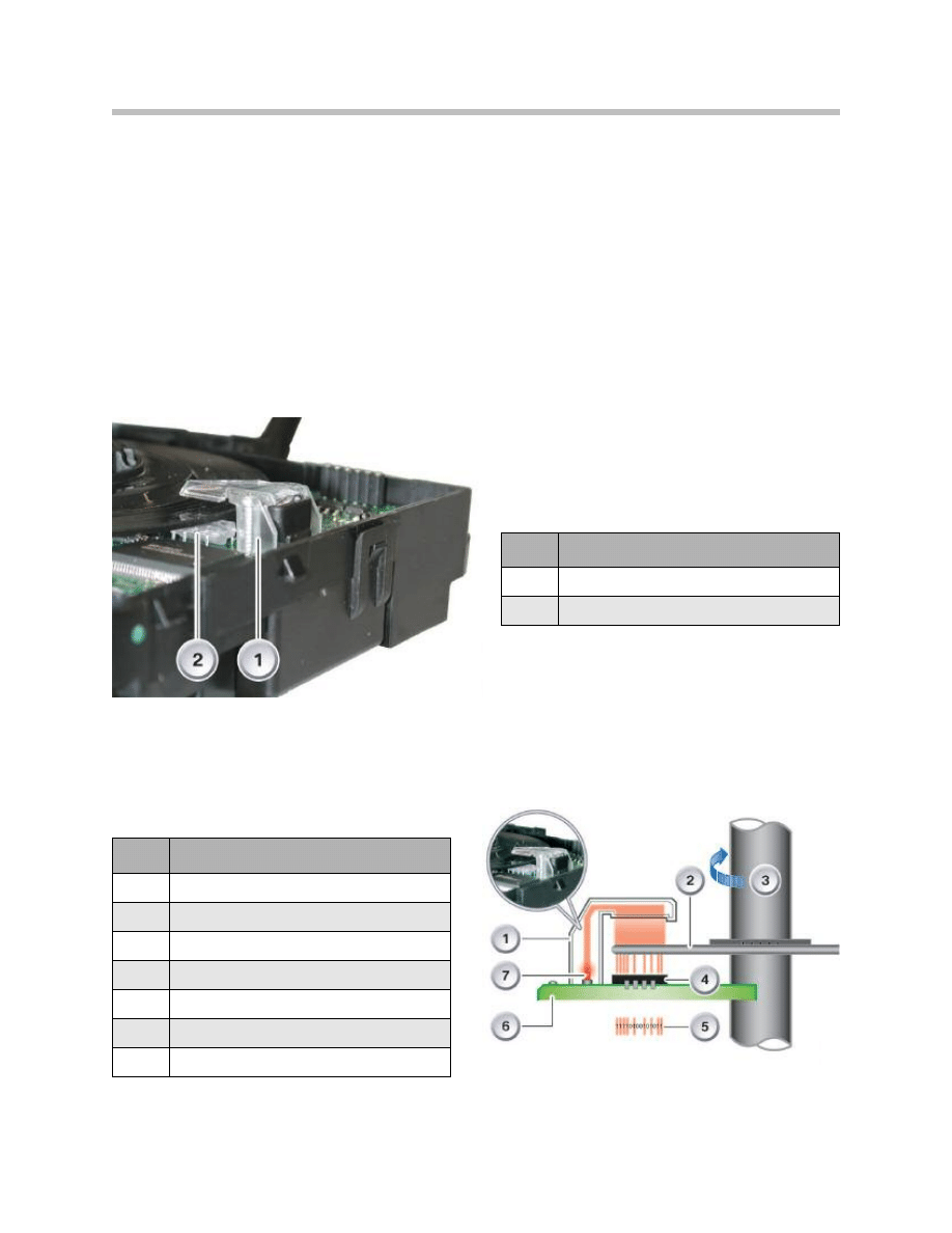
Optical Sensor
The optical sensor is designed as follows: LED and fibre optics unit The LED in connec-
tion with the fibre optics unit has the task of projecting light from the top onto the code
disc. The LED is soldered directly to the pc-board of the (SZL). The fibre optics unit is
secured by means of two screws to the pc-board. Together, the LED with fibre optics unit
and the line camera make up the optical sensor.
Line Camera
The line camera is located beneath the code disc. The line camera converts optical sig-
nals that penetrate through the code disc into electrical signals.
32
E70 Longitudinal Dynamics Systems
Index
Explanation
1
Line camera
2
Fibre optics unit with LED
Index
Explanation
1
Fibre optics unit
2
Code disc
3
Steering column
4
Line camera
5
Output: Conversion to electrical signals
6
PC-board
7
Light-emitting diode
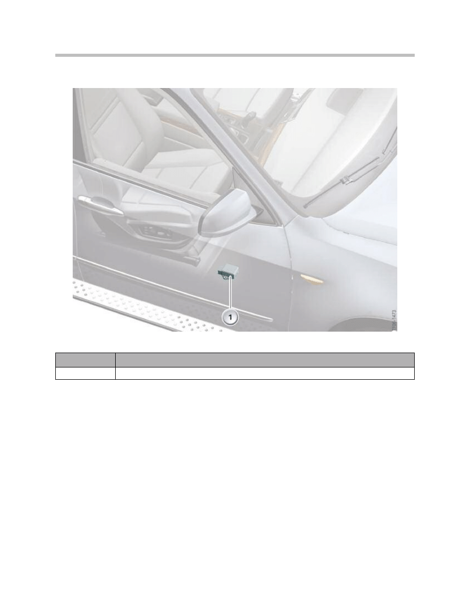
The DSC sensor is located under the front passenger seat and is available in two variants
in the E70:
• Vehicle without active steering, DSC sensor (designation MM3.8), containing a
– Transverse acceleration sensor.
– Longitudinal acceleration sensor.
– Yaw rate sensor in a housing.
• Vehicle with active steering, DSC sensor (designation MM3.2.2), containing.
– 2 redundant transverse acceleration sensors.
– Longitudinal acceleration sensor.
– 2 redundant yaw rate sensors in a housing.
33
E70 Longitudinal Dynamics Systems
DSC Sensor
Index
Explanation
1
DSC sensor
34
E70 Longitudinal Dynamics Systems
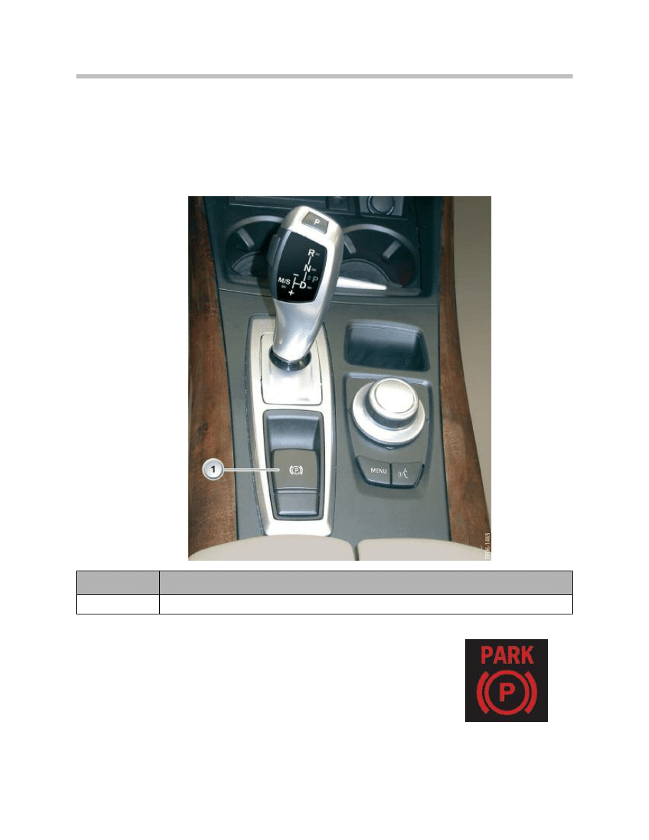
Electromechanical Parking Brake (EMF)
EMF Button
On the E70, the EMF button or the parking brake is located in the center console next to
the gear selector lever.
The EMF button is based on the function logic of a hand brake.
• Pull EMF button (1) up: Parking brake is activated
• Press EMF button (1) down: Parking brake is deactivated
Note: The indicator lamp in the instrument cluster shows
the driver when the EMF is activated.
Index
Explanation
1
EMF button
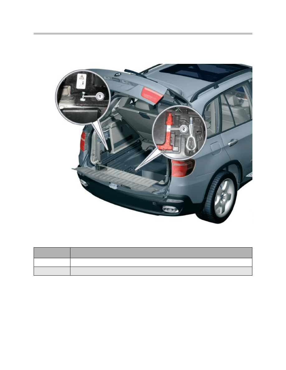
The E70 tool kit is located in the luggage compartment which includes a red handle for
the emergency release (2) of the EMF and the parking lock of the automatic gearbox.
The EMF emergency release cable (1) is located on the rear left behind the side trim
panel.
35
E70 Longitudinal Dynamics Systems
Emergency Release
Index
Explanation
1
Bowden cable, emergency release EMF
2
Handle for emergency release
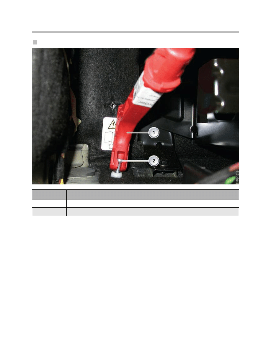
The opening in the handle for the emergency release (1) is attached to the EMF emer-
gency release cable as illustrated and the parking brake is released in the electromechan-
ical actuating unit by pulling the handle upwards.
36
E70 Longitudinal Dynamics Systems
Using the E70 EMF Emergency Release
Index
Explanation
1
Handle for emergency release
2
Bowden cable, emergency release EMF
37
E70 Longitudinal Dynamics Systems
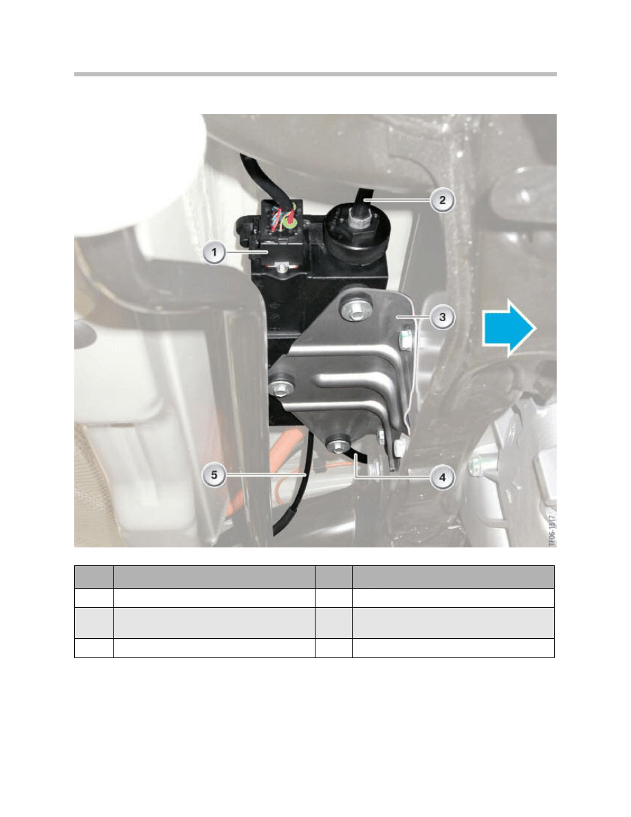
On the E70, the EMF actuating unit is located on the component carrier (3) on the
rear axle.
Index
Explanation
Index
Explanation
1
Electrical connection
4
Bowden cable, rear left wheel
2
Bowden cable, rear right wheel
5
Bowden cable, emergency release
3
Component carrier
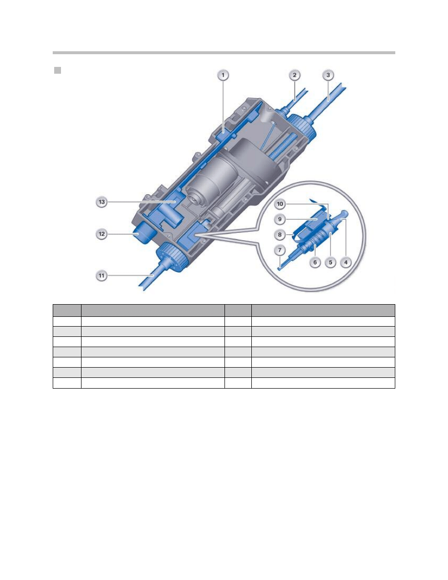
Electromechanical Actuating Unit
38
E70 Longitudinal Dynamics Systems
The EMF actuating unit is sealed watertight and the housing cannot be opened.
The EMF actuating unit contains the following main components:
• EMF control unit
• Electric motor
• Spindle gear mechanism
• Force sensor
The force sensor in the EMF actuating unit is a very important component for operation
of the parking brake. With its signals, the force sensor makes it possible for the EMF con-
trol unit to determine the actuating force. The actuating force is essential for securing the
required braking pressure.
EMF Actuating Unit Opened
Index
Explanation
Index
Explanation
1
EMF control unit (control electronics)
8
Flexible band
2
Bowden cable, emergency release
9
Force sensor pc-board
3
Bowden cable, rear left wheel
10
Force sensor magnet
4
Lock pin
11
Bowden cable, rear right wheel
5
Actuating piston
12
Electrical connection
6
Spring
13
EMF control unit (control electronics)
7
Emergency release cable
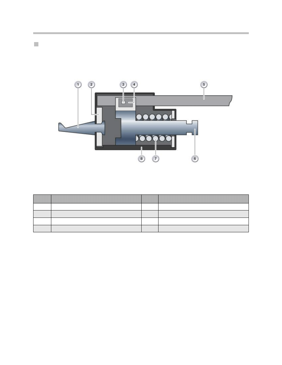
The housing of the force sensor consists of two halves. The lower section of the housing
(8) is made from pressure diecast aluminum so that it can take up the exerted forces.
The upper section of the housing is made of plastic, to which the force sensor pc-board
(5) with the Hall-IC (3) is secured.
The magnet (4) is fixed to the piston (6). The force sensor is located between the left and
right bowden cable assembly. During actuation, the piston (6) moves with the magnet
against the spring (7).
The travel range of spring compression is measured in accordance with the familiar Hall
principle. Since the spring data are defined, the EMF control unit can calculate the
applied force from the travel range and the spring data. The force sensor is calibrated at
the end of the assembly line.
39
E70 Longitudinal Dynamics Systems
Force Sensor
Index
Explanation
Index
Explanation
1
Hook
5
Force sensor pc-board
2
Retaining plate
6
Piston
3
Hall-IC
7
Spring
4
Magnet
8
Lower section of housing
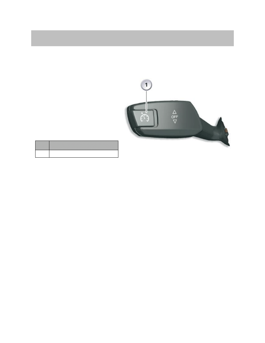
The operating and display philosophy on the DCC steering column stalk and in the
instrument cluster in the E70 is the same as that in other model series.
Functionally, the cruise control with
brake intervention DCC is integrated
in the DSC control unit. The DCC
functionality is realized by way of
communication with the partner con-
trol units of the DSC control unit in
the system network such as
DME/DDE, EGS, SZL and instrument
cluster.
The DCC function can be activated from 30 km/h/19 mph (up to max. 250km/h/155mph)
and is deactivated by similar factors as for cruise control:
• Brake pedal actuation
• Deactivation of DSC
• Activation of DTC
• Active DSC intervention
• Deactivation by the driver
• Speed is reduced below 22 km/h
• "N" engaged
• EMF function activated
DCC achieves a deceleration of max. 2.1 m/s² and an acceleration of about. 1.7 m/s².
The transverse acceleration is variably limited by the Curve Speed Limiter (CLS). The
primary emphasis has been placed on comfortable performance in this system configu-
ration. When cruise control with brake intervention is activated, the brake lights are also
activated in accordance with legal requirements in connection with a system related
braking operation DCC.
40
E70 Longitudinal Dynamics Systems
Cruise Control with Brake Intervention (DCC)
Index
Explanation
1
Button, select stored speed

Extended functions of the DCC compared to a conventional cruise control system:
• Active brake intervention to realize the set speed also when driving downhill
• Curve Speed Limiter (CLS) - adaptation of driving speed when cornering (transverse
acceleration).
This function limits the maximum transverse acceleration dependent on vehicle
speed with the aim of achieving the greatest possible agility in DCC mode. Driving
on winding country roads in a speed range from > 50 km/h/31mph to < 120
km/h/74mph is controlled with a value of 3.3 - 3.7 m/s². The value can increase up to
4.5 m/s for fast highway bends and slow lane changes at speeds between < 50
km/h/31mph and > 120 km/h/74mph.
• Comfort Dynamic System (CDS) - this enables a type of "manual throttle mode" on
the steering column stalk.
• Adapted downhill mode - the overrun fuel cutout and gear down shift are corre-
spondingly adapted.
41
E70 Longitudinal Dynamics Systems

Adjusting the Brake Shoes
The procedure for adjusting the parking brake shoes is the same as before:
Turn the adjusting screw using a screwdriver through the threaded hole in the wheel hub
(10 teeth).
Removing the Bowden Cable Assemblies
Note: The EMF must be set to service mode with the diagnostic tester before
performing any maintenance or service procedures (the parking brake
cannot be applied, EMF assumes the outermost position). The EMF will
not respond to an operating signal until service mode has been deacti-
vated again.
Necessary preparation:
• To remove emergency release bowden cable assembly in luggage compartment
(see Emergency Release). Use pointed pliers to press together the white clip while
pressing in the direction of the floor plate.
Remove the wheels, brake calipers and brake discs (according to repair instructions)
to expose the duo-servo brake shoes.
The heat shield must be removed on vehicles with Active Roll Stabilization (ARS)
and the ARS anti-roll bar lowered. (It is sufficient to release the ARS anti-roll bar at
the mounting points and to lower it.)
Unplug the electrical connector from the EMF actuating unit.
• To detach and expose the emergency release bowden cable assembly (Note: Clip
fastening behind wheel arch panel). Release spring clip on wheel carrier. Detach
nipple of cable assembly from brake show expander and pull the cable out of the
wheel carrier. Release the cable assembly from the clip on the rear axle carrier and
pull in the direction of the EMF actuating unit.
• Detach the carrier for the EMF actuating unit from the rear axle carrier and from the
EMF actuating unit and pull out.
• Screw the union nut on the rear left wheel cable assembly by 5-7 turns (left-hand
thread) into the spline shaft of the actuator. Then fit the twist lock (square) of the
threaded spindle in the guide in the actuator housing. The sleeve of the cable
assembly must lie flat on the actuator housing before fitting the union nut. Tighten
the union nut to 6 Nm. Attach the rear right wheel cable assembly to the mounting
point on the actuator and secure with the clip. Make sure that the cable is firmly fit-
ted. The cable assembly must lie flat on the actuator housing before fitting the
union nut. Tighten to 6 Nm.
42
E70 Longitudinal Dynamics Systems
Service Information

• Reinstallation takes place in the reverse order of removal. Fit the new EMF actuating
unit, cable assemblies first, in the package space. If it was necessary to slack off the
carrier from the EMF actuating unit, it must be resecured to the EMF actuating unit
and tightened to a torque of 4 ± 0.5 Nm. The component carrier must be secured to
the rear axle carrier to a torque of 19Nm±15 %. Before securing the cable assem-
blies to the wheel carrier (tightening torque 8 Nm), check that the brake cables are
securely attached in the brake shoe expander otherwise the EMF actuating unit may
be damaged as soon as it is operated.
Start-up
A new EMF actuating unit is always set to "service mode". This mode can be actively
reset with the diagnostic tester or it resets itself automatically on exceeding a defined
vehicle speed. The actuating unit is now in "standby mode". The EMF actuating unit
must then be encoded to the vehicle.
Initializing the Parking Brake
Note: The EMF must be initialized with the diagnostic tester after replacing
the drum brake linings.
Bedding in the Duo-servo Brake
If the brake shoes of the duo-servo brake are replaced as part of repair or maintenance
work, it is necessary to bed in the brake shoes before a sufficient holding effect may be
achieved. Also in this case, the special routine must be activated in the EMF with the
diagnostic tester.
The flashing indicator lamp in the instrument cluster signals that the bedding-in program
is ready.
The bedding-in program will be aborted and the normal parking brake function resumed
if the bedding-in is not started within 30 minutes of program activation or if the ignition is
switched off.
The bedding-in procedure can also be performed on the roller dynamometer.
43
E70 Longitudinal Dynamics Systems

Function on Brake Rolling Dynamometer
The Operation of the E70 parking brake can be tested on the brake rolling dynamometer.
As part of the road inspection, the rear axle brake can be tested with the engine running
by pulling the EMF button.
As part of the road inspection, the rear axle brake can be tested with the engine running
by pulling the EMF button. As a result, the EMF actuating unit is applied, the duo-servo
brake is applied and the vehicle normally jumps out of the roller of the test rig.
44
E70 Longitudinal Dynamics Systems
Document Outline
- Main Menu
- E70 Introduction
- E70 Glovebox
- E70 Powertrain
- E70 Gasoline Engines
- E70 Transmissions
- E70 Voltage Supply and Bus Systems
- E70 Car Access System 3
- E70 Energy Management
- E70 Chassis Dynamics
- E70 Lateral Dynamics Systems
- E70 Vertical Dynamics Systems
- E70 Longitudinal Dynamics Systems
- E70 Central Locking
- E70 Power Windows
- E70 Comfort Access
- E70 Wipe/Wash System
- E70 Panorama Glass Sunroof
- E70 Seats
- E70 Automatic Tailgate
- E70 Steering Column Switch Cluster
- E70 Exterior Lighting
- E70 Interior Lighting
- E70 Adaptive Headlight System
- E70 Park Distance Control
- E70 Rear-view Camera
- E70 Anti-Theft Alarm System
- E70 Outside Mirrors
- E70 Displays Indicators and Controls
- E70 Head-up Display
- E70 Information and Communication
- E70 Audio Systems
- E70 Rear Seat Entertainment
- E70 Climate Control Systems
- E70 Passive Safety Systems
Wyszukiwarka
Podobne podstrony:
04b E70 Lateral Dynamics Systems
04 3 F01 Longitudinal Dynamics Systems
05 Longitudinal Dynamics Systems
uproszczone ogloszenie o zamowieniu objetym dynamicznym system zakupow, ZAMÓWIENIA PUBLICZNE 3
Kontrola w zakresie dynamicznym systemu podwieszenia mostu nad rzeką Suir w Irlandii
Gorban A N singularities of transition processes in dynamical systems qualitative theory of critica
Natiello M , Solari H The user#s approach to topological methods in 3 D dynamical systems (WS, 2007)
05b4 E70 Adaptive Headlight System
03b E70 Car Access System 3
Brzechczyn, Krzysztof Metodologiczny status koncepcji totalitaryzmu a modelowanie dynamiki systemu
Vershik Graded Lie Algebras & Dynamical Systems (2001) [sharethefiles com]
Rodzina jako dynamiczny system[1]
04a E70 Chassis Dynamics
05a4 E70 Wipe Wash System
09 E70 Passive Safety Systems
04d E65 Speech Processing System
04 4 F01 Lateral Dynamics Systems
Pamięci dynamiczne RAM, Szkoła, Systemy Operacyjnie i sieci komputerowe, utk, semestr I
więcej podobnych podstron