
DISTRIBUTION STATEMENT A: Approved for public release; distribution is unlimited.
NONRESIDENT
TRAINING
COURSE
December 1993
Electronics Technician
Volume 4—Radar Systems
NAVEDTRA 14089

DISTRIBUTION STATEMENT A: Approved for public release; distribution is unlimited.
Although the words “he,” “him,” and
“his” are used sparingly in this course to
enhance communication, they are not
intended to be gender driven or to affront or
discriminate against anyone.

i
PREFACE
By enrolling in this self-study course, you have demonstrated a desire to improve yourself and the Navy.
Remember, however, this self-study course is only one part of the total Navy training program. Practical
experience, schools, selected reading, and your desire to succeed are also necessary to successfully round
out a fully meaningful training program.
COURSE OVERVIEW: In completing this nonresident training course, you will demonstrate a
knowledge of the subject matter by correctly answering questions on the following subjects: Define the
basic terms associated with radar and radar systems; identify the basic components of and explain the
operation of the Navy’s standard surface search radars, air search radars, three-coordinate air search radars,
carrier controlled approach (CCA) and ground controlled approach (GCA) radars, and planned position
indicators (PPI) and repeaters; identify the basic components of and explain the operation of identification,
friend or foe (IFF) systems, direct altitude and identity readout (DAIR) systems, naval tactical data (NTDS)
systems, and radar distribution switchboards; and identify and explain the safety hazards associated with
radar systems.
THE COURSE: This self-study course is organized into subject matter areas, each containing learning
objectives to help you determine what you should learn along with text and illustrations to help you
understand the information. The subject matter reflects day-to-day requirements and experiences of
personnel in the rating or skill area. It also reflects guidance provided by Enlisted Community Managers
(ECMs) and other senior personnel, technical references, instructions, etc., and either the occupational or
naval standards, which are listed in the Manual of Navy Enlisted Manpower Personnel Classifications
and Occupational Standards, NAVPERS 18068.
THE QUESTIONS: The questions that appear in this course are designed to help you understand the
material in the text.
VALUE: In completing this course, you will improve your military and professional knowledge.
Importantly, it can also help you study for the Navy-wide advancement in rate examination. If you are
studying and discover a reference in the text to another publication for further information, look it up.
1993 Edition Prepared by
ETCS(SW) Linda Villareal
Published by
NAVAL EDUCATION AND TRAINING
PROFESSIONAL DEVELOPMENT
AND TECHNOLOGY CENTER
NAVSUP Logistics Tracking Number
0504-LP-026-7550

ii
Sailor’s Creed
“I am a United States Sailor.
I will support and defend the
Constitution of the United States of
America and I will obey the orders
of those appointed over me.
I represent the fighting spirit of the
Navy and those who have gone
before me to defend freedom and
democracy around the world.
I proudly serve my country’s Navy
combat team with honor, courage
and commitment.
I am committed to excellence and
the fair treatment of all.”

CONTENTS
CHAPTER
Page
1. Introduction to Basic Radar Systems. . . . . . . . . . . . . . . . . . 1-1
2. Radar Systems Equipment Conjurations . . . . . . . . . . . . . . 2-1
3. Radar System Interfacing . . . . . . . . . . . . . . . . . . . . . . . 3-1
4. Safety . . . . . . . . . . . . . . . . . . . . . . . . . . . . . . . 4-1
APPENDIX
I. Glossary . . . . . . . . . . . . . . . . . . . . . . . . . . . . . . AI-1
II. References . . . . . . . . . . . . . . . . . . . . . . . . . . . . AII-1
Index . . . . . . . . . . . . . . . . . . . . . . . . . . . . . . . . . . INDEX-1
. . .
iii

SUMMARY OF THE ELECTRONICS TECHNICIAN
TRAINING SERIES
This series of training manuals was developed to replace the Electronics
Technician 3 & 2 TRAMAN. The content is directed toward personnel working
toward advancement to Electronics Technician Second Class.
The nine volumes in the series are based on major topic areas with which the
ET2 should be familiar. Volume 1, Safety, provides an introduction to general safety
as it relates to the ET rating. It also provides both general and specific information
on electronic tag-out procedures, man-aloft procedures, hazardous materials (i.e.,
solvents, batteries, and vacuum tubes), and radiation hazards. Volume 2,
Administration, discusses COSAL updates, 3-M documentation, supply paperwork,
and other associated administrative topics. Volume 3, Communications Systems,
provides a basic introduction to shipboard and shore-based communication systems.
Systems covered include man-pac radios (i.e., PRC-104, PSC-3) in the hf, vhf, uhf,
SATCOM, and shf ranges. Also provided is an introduction to the Communications
Link Interoperability System (CLIPS). Volume 4, Radar Systems, is a basic
introduction to air search, surface search, ground controlled approach, and carrier
controlled approach radar systems.
Volume 5, Navigation Systems, is a basic
introduction to navigation systems, such as OMEGA, SATNAV, TACAN, and
man-pac systems. Volume 6, Digital Data System, is a basic introduction to digital
data systems and incIudes discussions about SNAP II, laptop computers, and desktop
computers. Volume 7, Antennas and Wave Propagation, is an introduction to wave
propagation, as it pertains to Electronics Technicians, and shipboard and
shore-based antennas. Volume 8, System Concepts, discusses system interfaces,
troubleshooting, sub-systems, dry air, cooling, and power systems. Volume 9,
Electro-Optics, is an introduction to night vision equipment, lasers, thermal imaging,
and fiber optics.
iv

v
INSTRUCTIONS FOR TAKING THE COURSE
ASSIGNMENTS
The text pages that you are to study are listed at
the beginning of each assignment. Study these
pages carefully before attempting to answer the
questions. Pay close attention to tables and
illustrations and read the learning objectives.
The learning objectives state what you should be
able to do after studying the material. Answering
the questions correctly helps you accomplish the
objectives.
SELECTING YOUR ANSWERS
Read each question carefully, then select the
BEST answer. You may refer freely to the text.
The answers must be the result of your own
work and decisions. You are prohibited from
referring to or copying the answers of others and
from giving answers to anyone else taking the
course.
SUBMITTING YOUR ASSIGNMENTS
To have your assignments graded, you must be
enrolled in the course with the Nonresident
Training Course Administration Branch at the
Naval Education and Training Professional
Development
and
Technology
Center
(NETPDTC). Following enrollment, there are
two ways of having your assignments graded:
(1) use the Internet to submit your assignments
as you complete them, or (2) send all the
assignments at one time by mail to NETPDTC.
Grading on the Internet:
Advantages to
Internet grading are:
• you may submit your answers as soon as
you complete an assignment, and
• you get your results faster; usually by the
next working day (approximately 24 hours).
In addition to receiving grade results for each
assignment, you will receive course completion
confirmation once you have completed all the
assignments.
To
submit
your
assignment
answers via the Internet, go to:
http://courses.cnet.navy.mil
Grading by Mail: When you submit answer
sheets by mail, send all of your assignments at
one time. Do NOT submit individual answer
sheets for grading. Mail all of your assignments
in an envelope, which you either provide
yourself or obtain from your nearest Educational
Services Officer (ESO). Submit answer sheets
to:
COMMANDING OFFICER
NETPDTC N331
6490 SAUFLEY FIELD ROAD
PENSACOLA FL 32559-5000
Answer Sheets:
All courses include one
“scannable” answer sheet for each assignment.
These answer sheets are preprinted with your
SSN, name, assignment number, and course
number. Explanations for completing the answer
sheets are on the answer sheet.
Do not use answer sheet reproductions: Use
only the original
answer
sheets that
we
provide—reproductions will not work with our
scanning equipment and cannot be processed.
Follow the instructions for marking your
answers on the answer sheet. Be sure that blocks
1, 2, and 3 are filled in correctly. This
information is necessary for your course to be
properly processed and for you to receive credit
for your work.
COMPLETION TIME
Courses must be completed within 12 months
from the date of enrollment. This includes time
required to resubmit failed assignments.

vi
PASS/FAIL ASSIGNMENT PROCEDURES
If your overall course score is 3.2 or higher, you
will pass the course and will not be required to
resubmit assignments. Once your assignments
have been graded you will receive course
completion confirmation.
If you receive less than a 3.2 on any assignment
and your overall course score is below 3.2, you
will be given the opportunity to resubmit failed
assignments.
You
may
resubmit
failed
assignments only once. Internet students will
receive notification when they have failed an
assignment--they may then resubmit failed
assignments on the web site. Internet students
may
view
and
results
for
failed
assignments from the web site. Students who
submit by mail will receive a failing result letter
and a new answer sheet for resubmission of each
failed assignment.
COMPLETION CONFIRMATION
After successfully completing this course, you
will receive a letter of completion.
ERRATA
Errata are used to correct minor errors or delete
obsolete information in a course. Errata may
also be used to provide instructions to the
student.
If a course has an errata, it will be
included as the first page(s) after the front cover.
Errata for all courses can be accessed and
viewed/downloaded at:
http://www.advancement.cnet.navy.mil
STUDENT FEEDBACK QUESTIONS
We value your suggestions, questions, and
criticisms on our courses. If you would like to
communicate with us regarding this course, we
encourage you, if possible, to use e-mail. If you
write or fax, please use a copy of the Student
Comment form that follows this page.
For subject matter questions:
E-mail:
n315.products@cnet.navy.mil
Phone:
Comm: (850) 452-1001, Ext. 1713
DSN: 922-1001, Ext. 1713
FAX: (850) 452-1370
(Do not fax answer sheets.)
Address:
COMMANDING OFFICER
NETPDTC N315
6490 SAUFLEY FIELD ROAD
PENSACOLA FL 32509-5237
For
enrollment,
shipping,
grading,
or
completion letter questions
E-mail:
fleetservices@cnet.navy.mil
Phone:
Toll Free: 877-264-8583
Comm: (850) 452-1511/1181/1859
DSN: 922-1511/1181/1859
FAX: (850) 452-1370
(Do not fax answer sheets.)
Address:
COMMANDING OFFICER
NETPDTC N331
6490 SAUFLEY FIELD ROAD
PENSACOLA FL 32559-5000
NAVAL RESERVE RETIREMENT CREDIT
If you are a member of the Naval Reserve, you
may earn retirement points for successfully
completing this course, if authorized under
current directives governing retirement of Naval
Reserve personnel. For Naval Reserve retire-
ment, this course is evaluated at 5 points. (Refer
to
Administrative
Procedures
for
Naval
Reservists on Inactive Duty, BUPERSINST
1001.39, for more information about retirement
points.)

vii
Student Comments
Course Title:
Electronics Technician, Volume 4—Radar Systems
NAVEDTRA:
14089
Date:
We need some information about you:
Rate/Rank and Name:
SSN:
Command/Unit
Street Address:
City:
State/FPO:
Zip
Your comments, suggestions, etc.:
Privacy Act Statement:
Under authority of Title 5, USC 301, information regarding your military status is
requested in processing your comments and in preparing a reply. This information will not be divulged without
written authorization to anyone other than those within DOD for official use in determining performance.
NETPDTC 1550/41 (Rev 4-00

CHAPTER 1
INTRODUCTION TO BASIC RADAR
The Navy Electricity and Electronics Training
Series (NEETS) modules, especially module 18, Radar
Principles, provide information that is basic to your
understanding of this volume. This volume will discuss
radar and radar systems as you may encounter them as
an Electronics Technician at your command. You
should refer to NEETS module 18 and Electronics
Installation and Maintenance Book (EIMB), Radar and
Electronic Circuits, on a regular basis to ensure that you
have a complete understanding of the subject matter
covered in this volume.
As an Electronics Technician, Second Class, and
possible work center supervisor, you must understand
the basic radar principles and safety requirements for
radar maintenance. However, due to luck of the draw,
your first assignment may not afford you exposure to
radar systems. Our intention with this volume is NOT
to teach you every radar system the Navy uses, but
simply to familiarize you with the radars and their
general maintenance principles.
You will be able to identify the equipment
requirements and general operation of the three basic
radar systems covered in chapter 1. You’ll become
familiar with the nomenclature of specific radars used
in the Navy today as we discuss them in chapter 2. Then,
armed with all that knowledge you will easily grasp the
system concepts addressed in chapter 3. And before you
go out to tackle the radar world, chapter 4 will give you
necessary safety information specific to radar
maintenance.
When you arrive at your next command as a second
class with work center responsibilities for a radar
maintenance shop, you will be ready.
BASIC RADAR CONCEPTS
The term radar is an acronym made up of the words
radio, detection, and ranging. It refers to electronic
equipment that detects the presence, direction, height,
and distance of objects by using reflected
electromagnetic energy.
The frequency of
electromagnetic energy used for radar is unaffected by
darkness and also penetrates weather. This permits
radar systems to determine the position of ships, planes,
and land masses that are invisible to the naked eye
because of distance, darkness, or weather.
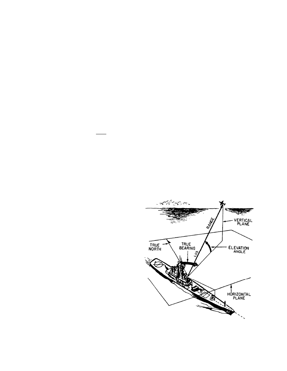
Radar systems provide only a limited field of view
and require reference coordinate systems to define the
positions of the detected objects. Radar surface angular
measurements are normally made in a clockwise
direction from TRUE NORTH, as shown in figure 1-1,
or from the heading line of a ship or aircraft. The actual
radar location is the center of this coordinate system.
Figure 1-1 contains the basic terms that you need to
know to understand the coordinate system. Those terms
are defined in the following paragraph.
The surface of the earth is represented by an
imaginary flat plane, known as the HORIZONTAL
PLANE, which is tangent (or parallel) to the earth’s
surface at that location. All angles in the up direction
are measured in a secondary imaginary plane, known as
the VERTICAL PLANE, which is perpendicular to the
horizontal plane. The line from the radar set directly to
the object is referred to as the LINE OF SIGHT (LOS).
The length of this line is called RANGE. The angle
Figure 1-1.—Radar reference coordinates.
1-1

between the horizontal plane and the LOS is the
ELEVATION ANGLE. The angle measured
clockwise from true north in the horizontal plane is
called the TRUE BEARING or AZIMUTH angle.
Information based on these terms describes the location
of an object with respect to the antenna, giving the
operator data on range, bearing, and altitude.
RANGE/BEARING/ALTITUDE
Using the coordinate system discussed above, radar
systems provide early detection of surface or air objects,
giving extremely accurate information on distance,
direction, height, and speed of the objects. The visual
radar data required to determine a target’s position and
to track the target is usually displayed on a specially
designed cathode-ray tube (crt) installed in a unit known
as a planned position indicator (ppi).
Radar is also used to guide missiles to targets and to
direct the firing of gun systems. Other types of radar
provide long-distance surveillance and navigation
information.
Bearing and range (and in the case of aircraft,
altitude) are necessary to determine target movement.
It is very important that you understand the limitations
of your radar system in the areas of range, hewing, and
altitude.
Range
Radar measurement of range (or distance) is made
possible because of the properties of radiated
electromagnetic energy. This energy normally travels
through space in a straight line, at a constant speed, and
will vary only slightly because of atmospheric and
weather conditions. The range to an object, in nautical
miles, can be determined by measuring the elapsed time
(in microseconds) during the round trip of a radar pulse
and dividing this quantity by the number of
microseconds required for a radar pulse to travel 2
nautical miles (12.36). In equation form this is:
elapsed time
range (nautical miles) =
12.36
MINIMUM RANGE.— Radar duplexers
alternately switch the antenna between the transmitter
and receiver so that one antenna can be used for both
functions. The timing of this switching is critical to the
operation of the radar and directly affects the minimum
range of the radar system. A reflected pulse will not be
received during the transmit pulse and subsequent
receiver recovery time. Therefore, any reflected pulses
from close targets that return before the receiver is
connected to the antenna will be undetected.
MAXIMUM RANGE.— The maximum range of a
pulse radar system depends upon carrier frequency peak
power of the transmitted pulse, pulse repetition
frequency (prf), or pulse repetition rate (prr), and
receiver sensitivity.
The peak power of the pulse determines what
maximum range the pulse can travel to a target and still
return a usable echo. A usable echo is the smallest signal
detectable by a receiver that can be processed and
presented on an indicator.
The prr will determine the frequency that the
indicator is reset to the zero range. With the leading
edge of each transmitted pulse, the indicator time base
used to measure the returned echoes is reset, and a new
sweep appears on the screen. If the transmitted pulse is
shorter than the time required for an echo to return, that
target will be indicated at a false range in a different
sweep. For example, the interval between pulses is 610
sec with a repetition rate of 1640 pulses per second.
Within this time the radar pulse can go out and come
back a distance equal to 610 sec ’ 164 yards per sec, or
100,000 yards, which becomes the scope’s sweep limit.
Echoes from targets beyond this distance appear at a
false range. Whether an echo is a true target or a false
target can be determined by simply changing the prr.
RANGE ACCURACY.— The shape and width of
the rf pulse influences minimum range, range accuracy,
and maximum range. The ideal pulse shape is a square
wave that has vertical leading and trailing edges. A
sloping trailing edge lengthens the pulse width. A
sloping leading edge provides no definite point from
which to measure elapsed time on the indicator time
base.
Other factors affecting range are the antenna height,
antenna beam width, and antenna rotation rate. A higher
antenna will create a longer radar horizon, which allows
a greater range of detection.
Likewise, a more
concentrated beam has a greater range capability since
it provides higher energy density per unit area. Also,
because the energy beam would strike each target more
times, a slower antenna rotation provides stronger echo
returns and a greater detection range for the radar.
Given the range information, the operator knows the
distance to an object, but information on bearing is still
required to determine in which direction from the ship
the target lies.
1-2
Bearing
Radar bearing is determined by the echo signal
strength as the radiated energy lobe moves past the
target. Since search radar antennas move continuously,
the point of maximum echo return is determined either
by the detection circuitry as the beam passes the target
or visually by the operator.
Weapons control and
guidance radar systems are positioned to the point of
maximum signal return and maintained at that position
either manually or by automatic tracking circuits.
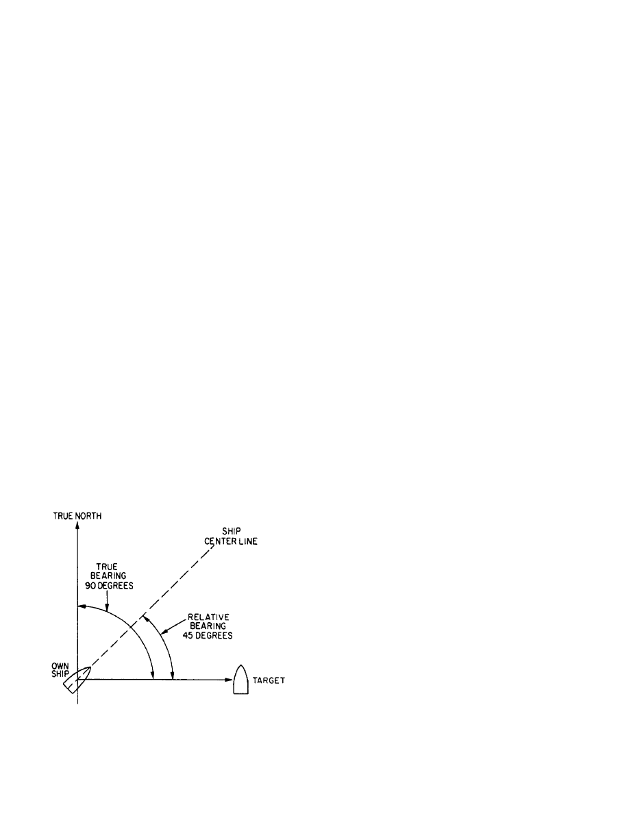
TRUE BEARING.— The angle between true north
and a line pointed directly at a target is called the true
bearing (referenced to true north) of a radar target. This
angle is measured in the horizontal plane and in a
clockwise direction from true north.
RELATIVE BEARING.— The angle between the
centerline of your own ship or aircraft and a line pointed
directly at a target is called the relative bearing of the
radar target. This angle is measured in a clockwise
direction from the centerline.
Both true and relative bearing angles are illustrated
in figure 1-2.
Most surface search radars will provide only range
and bearing information. If the operator had a need to
direct air traffic or to track incoming missiles, the radar
would also have to provide altitude.
Altitude
An operator can determine the altitude of a target by
adjusting a movable height line on a height indicator to
Figure 1-2.—True and relative bearings.
the point where it bisects the center of the target. The
altitude is then displayed by an altitude dial or digital
readout. A search radar system that detects altitude as
well as range and bearing is called a three-dimensional
(3D) radar.
Altitude or height-finding radars use a very narrow
beam in the vertical plane. This beam is scanned in
elevation, either mechanically or electronically, to
pinpoint targets. Tracking and weapons-control radar
systems commonly use mechanical elevation scanning
techniques. This requires moving the antenna or
radiation source mechanically. Most air search radars
use electronic elevation scanning techniques. Some
older air search radar systems use a mechanical
elevation scanning device; however, these are being
replaced by electronically-scanned radar systems.
RADAR DETECTING METHODS
Radar systems are normally divided into
operational categories based on energy transmission
methods. Although the pulse methcd is the most
common method of transmitting radar energy, two other
methods are sometimes used in special applications.
These are the continuous wave (cw) method and the
frequency modulation (fm) method.
Continuous Wave
The continuous wave (cw) method uses the Doppler
effect to detect the presence and speed of an object
moving toward or away from the radar. The system is
unable to determine the range of the object or to
differentiate between objects that lie in the same
direction and are traveling at the same speed. It is
usually used by fire control systems to track fast moving
targets at close range.
Frequency Modulation
With the frequency modulation (fm) method,
energy is transmitted as radio frequency (rf) waves that
continuously vary, increasing and decreasing, from a
fixed reference frequency. Measuring the difference
between the frequency of the returned signal and the
frequency of the radiated signal will give an indication
of range. This system works well with stationary or
slowly-moving targets, but it is not satisfactory for
locating moving objects. It is used in aircraft altimeters
that give a continuous reading of how high the aircraft
is above the earth.
1-3

Pulse Modulation
With the pulse modulation method, depending on
the type of radar, energy is transmitted in pulses that vary
from less than 1 microsecond to 200 microseconds. The
time interval between transmission and reception is
computed and converted into a visual indication of range
in miles or yards.
Pulse radar systems can also be
modified to use the Doppler effect to detect a moving
object. The Navy uses pulse modulation radars to a
great extent.
FACTORS AFFECTING RADAR
PERFORMANCE
Radar accuracy is a measure of the ability of a radar
system to determine the correct range, bearing, and in
some cases, altitude of an object. The degree of
accuracy is primarily determined by the resolution of the
radar system and atmospheric conditions.
Range Resolution
Range resolution is the ability of a radar to resolve
between two targets on the same bearing, but at slightly
different ranges.
The degree of range resolution
depends on the width of the transmitted pulse, the types
and sizes of targets, and the efficiency of the receiver
and indicator.
Bearing Resolution
Bearing, or azimuth, resolution is the ability of a
radar system to separate objects at the same range but at
slightly different bearings. The degree of bearing
resolution depends on radar beamwidth and the range of
the targets. The physical size and shape of the antenna
determines beamwidth. Two targets at the same range
must be separated by at least one beamwidth to be
distinguished as two objects.
Earlier in this chapter, we talked about other internal
characteristics of radar equipment that affect range
performance. But there are also external factors that
effect radar performance. Some of those are the skill of
the operator; size, composition, angle, and altitude of the
target; possible electronic-countermeasure (ECM)
activity; readiness of equipment (completed PMS
requirements); and weather conditions
Atmospheric Conditions
Several conditions within the atmosphere can have
an adverse effect on radar performance. A few of these
are temperature inversion, moisture lapse, water
droplets, and dust particles.
Either temperature inversion or moisture lapse,
alone or in combination, can cause a huge change in the
refraction index of the lowest few-hundred feet of
atmosphere. The result is a greater bending of the radar
waves passing through the abnormal condition. The
increased bending in such a situation is referred to as
DUCTING, and may greatly affect radar performance.
The radar horizon may be extended or reduced,
depending on the direction in which the radar waves are
bent. The effect of ducting is illustrated in figure 1-3.
Water droplets and dust particles diffuse radar
energy through absorption, reflection, and scattering.
This leaves less energy to strike the target so the return
echo is smaller. The overall effect is a reduction in
usable range. Usable range varies widely with weather
conditions.
The higher the frequency of the radar
system, the more it is affected by weather conditions
such as rain or clouds.
All radar systems perform the same basic functions
of detection, so, logically, they all have the same basic
equipment requirements. Next, we will talk about that
basic radar system.
BASIC RADAR SYSTEMS
Radar systems, like other complex electronics
systems, are composed of several major subsystems and
many individual circuits.
Although modern radar
systems are quite complicated, you can easily
understand their operation by using a basic block
diagram of a pulsed radar system.
FUNDAMENTAL RADAR SYSTEM
Since most radars used today are some variation of
the pulse radar system, the units we discuss in this
section will be those used in a pulse radar. All other
Figure 1-3.—Ducting effect on the radar wave.
1-4
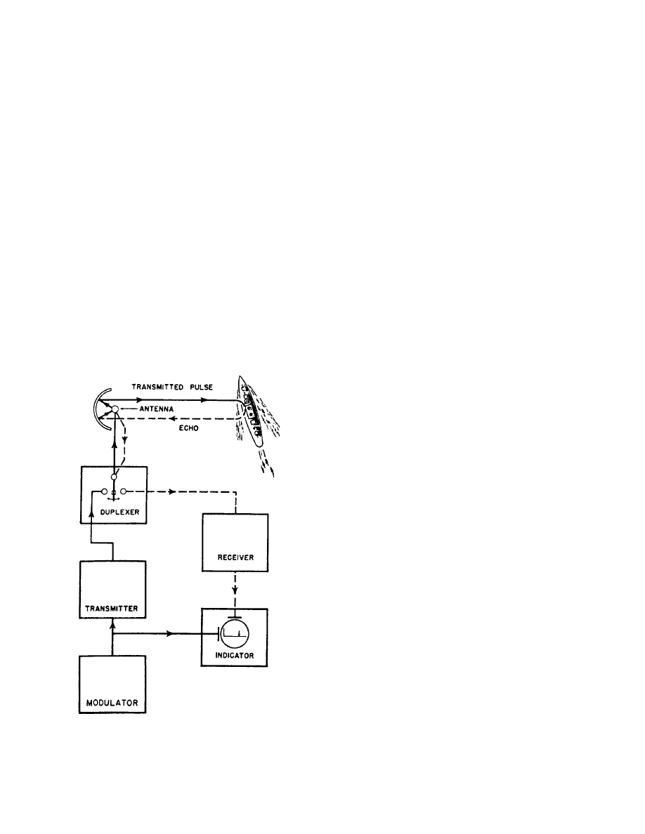
types of radars use some variations of these units, and
we will explain those variations, as necessary in the next
chapter. For now, let’s look at the block diagram in
figure 1-4.
Modulator
You can see on the block diagram that the heart of
the radar system is the modulator. It generates all the
necessary timing pulses (triggers) for use in the radar
and associated systems. Its function is to ensure that all
subsystems making up the radar system operate in a
definite time relationship with each other and that the
intervals between pulses, as well as the pulses
themselves, are of the proper length.
Transmitter
The transmitter generates powerful pulses of
electromagnetic energy at precise intervals. The
required power is obtained by using a high-power
microwave oscillator, such as a magnetron, or a
microwave amplifier, such as a klystron, that is supplied
by a low-power rf source. (You can review the
Figure 1-4.—Block diagram of fundamental radar system.
construction and operation of microwave components
in NEETS module 11, Microwave Principles.)
Duplexer
The duplexer is essentially an electronic switch that
permits a radar system to use a single antenna to both
transmit and receive. The duplexer must connect the
antenna to the transmitter and disconnect the antenna
from the receiver for the duration of the transmitted
pulse. As we mentioned previously, the switching time
is called receiver recovery time, and must be very fast if
close-in targets are to be detected.
Antenna System
The antenna system routes the pulse from the
transmitter, radiates it in a directional beam, picks up the
returning echo and passes it to the receiver with a
minimum of loss. The antenna system includes the
antenna, transmission lines, and waveguide from the
transmitter to the antenna, and transmission lines and
waveguide from the antenna to the receiver.
Receiver
The receiver accepts the weak rf echoes from the
antenna system and routes them to the indicator as
discernible video signals. Because the radar
frequencies are very high and difficult to amplify, a
superheterodyne receiver is used to convert the echoes
to a lower frequency, called the intermediate frequency
(IF), which is easier to amplify.
Indicator
The indicator uses the video output of the receiver
to produce a visual indication of target information
including range and bearing (or in the case of
height-finding indicators, range and height).
TYPES OF RADAR SYSTEMS
Because of different design parameters, no single
radar set can perform all the many radar functions
required for military use. The large number of radar
systems used by the military has forced the development
of a joint-services classification system for accurate
identification of radars.
Radar systems are usually classified according to
their specific function and installation vehicle. The
joint-service standardized classification system divides
these broad categories for more precise identification.
1-5
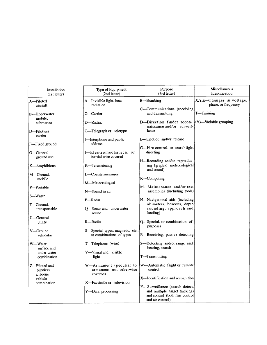
Table 1-1 is a listing of equipment identification
indicators. You can use this table and the radar
nomenclature to identify the parameters of a particular
radar set.
If you use the table to find the parameters of an
AN/FPS-35, you will see that it is a fixed (F) radar (P)
for detecting and search (S). The AN indicates
Army/Navy and the 35 is the model number.
Since no single radar system can fulfill all of the
requirements of modern warfare, most modern
warships, aircraft, and shore installations have several
radar sets, each performing a specific function. A
shipboard radar installation may include surface search
and navigation radars, an air search radar, a
height-finding radar, and various fire control radars.
Surface Search and Navigation
The primary function of a surface search radar is to
maintain a 360-degree search for all targets within
line-of-sight distance from the radar and to detect and
Table 1-1.—Table of Equipment Indicators
1-6

determine the accurate ranges and bearing of surface
targets and low-flying aircraft.
The following are some applications of surface
search radars:
Indicate the presence of surface craft and aid in
determining their course and speed
Coach fire control radar onto a surface target
Provide security against attack at night, during
conditions of poor visibility, or from behind a
smoke screen
Aid in scouting
Obtain range and bearing on prominent
landmarks and buoys as an aid to piloting,
especially at night and in conditions of poor
visibility
Facilitate station keeping
Detect low-flying aircraft
Detect certain weather phenomena
Detect submarine periscopes
Aid in the control of small craft during boat and
amphibious operations
Navigation radars fall into the same general
category as surface search radars. As the name implies,
navigation radars are used primarily as an aid to navigate
or pilot the ship.
This type of radar has a shorter
operating range and higher resolution than most surface
search radars. Because the navigation and surface
search radars share the same general operating
characteristics, both radar types can be used
simultaneously with one covering longer ranges, while
the other covers distances closer to the ship. The use of
radars for navigation is discussed further in Electronics
Technician, Volume 5—Navigation.
So now, with surface search and navigation radars
on line, the ship is aware of all surface targets, land
masses, and low-flying aircraft. But, to protect itself
from fighter planes, incoming missiles, and other targets
in the upper skies, the ship requires a different type of
radar.
Air Search
The primary function of an air search radar is to
maintain a 360-degree surveillance from the surface to
high altitudes and to detect and determine ranges and
bearings of aircraft targets over relatively large areas.
The following are some applications of air search
radar:
Early warning of approaching aircraft and
missiles, providing the direction from which an
attack could come. This allows time to bring
anti-aircraft defenses to the proper degree of
readiness and to launch fighters if an air attack is
imminent.
Constant observation of movement of enemy
aircraft, once detected, to guide combat air patrol
(CAP) aircraft to a position suitable for an
intercept
Provide security against attacks at night and
during times of poor visibility
Provide information used for aircraft control
during operations requiring a specific geographic
track (such as an anti-submarine barrier or search
and rescue pattern)
Together, surface and air search radars provide a
good early warning system. However, the ship must be
able to determine altitude to effectively intercept any air
target. This requires still another type of radar.
Height Finding
The primary function of a height-finding radar
(sometimes referred to as a 3D or three-coordinate
radar) is to compute accurate ranges, bearings, and
altitudes of targets detected by air search radar. This
information is used to direct fighter aircraft during
interception of air targets.
The height-finding radar is different from the air
search radar in that it has a higher transmitting
frequency, higher output power, a much narrower
vertical beamwidth, and requires a stabilized antenna for
altitude accuracy.
The following are some applications of
height-finding radar:
Obtain range, bearing, and altitude data on
enemy aircraft and missiles to assist in the
guidance of CAP aircraft
Provide precise range, bearing, and height
information for fast and accurate initial
positioning of fire control tracking radars
Detect low-flying aircraft
1-7

Determine range to distant land masses
Track aircraft over land
Detect certain weather phenomena
Track weather balloons
As we stated previously, the modern warship has
several radars. Each radar is designed to fulfill a
particular need, but may be capable of performing
other functions. For example, most height-finding
radars can be used as secondary air search radars; in
emergencies, fire control radars have served as
surface search radars.
In this chapter we looked at general radar operation
and the three types of radars most frequently maintained
by ETs. Tracking radars, missile-guidance radars, and
airborne radars are also critical to Navy readiness;
however, they are not normally maintained by ETs and
will not be covered in this TRAMAN.
Because there are so many different models of radar
equipment, the radars and accessories we describe in
this volume are limited to those common to a large
number of ships or shore stations. In our discussion of
specific equipments in the next chapter, we will
purposely leave out older equipment currently installed
in the fleet, but scheduled for replacement.
1-8
CHAPTER 2
RADAR SYSTEMS EQUIPMENT CONFIGURATIONS
In chapter 1, we discussed the configuration of a
training, you can become an expert maintainer of ANY
basic pulse radar system and the three basic types of
radar sets. We cannot cover in one chapter every radar
used by the Navy or every application of radars at the
various units. Therefore, this chapter will present only
a general overview of commonly used radars. We will
not teach you specific equipment, but will help you
identify and understand the operation of surface
search/navigation radars, air search radars, 3D radars,
CCA/GCA radars, and various repeaters used in the
Navy today. For each type of radar, we will provide a
basic system description, followed by its “theory of
operation” and a brief explanation of the maintenance
concept.
Most of the radar equipment discussed in this
chapter has specific maintenance training available.
However, except for certain crypto equipment, you do
not need specific training to work on the gear. By
combining the information in the appropriate technical
manual with your extensive basic electronics
background from “A” school and the general knowledge
you get through training manuals and on-the-job
electronic equipment.
You’ll be surprised at how much you can figure out
on your own. And if you ever get stumped, there are
ways to get help.
You may request maintenance
assistance from tenders, repair ships, Mobile Technical
Units (MOTUs), or NAVSEA field activities. In
addition, Direct Fleet Support (DFS) will resolve
maintenance repair problems beyond the capability of
ship’s force, Ship Repair Facilities (SRFs), Intermediate
Maintenance Activities (IMAs), and MOTU personnel.
If you need DFS assistance, submit a request to the
applicable NAVSEACEN via your type commander, as
prescribed in NAVSEAINST 4350.6.
The first radars we’ll talk about are the surface
search and navigation radars.
SURFACE SEARCH AND NAVIGATION
RADARS
Recall from chapter 1 that the two main functions
of surface search and navigation radars are to (1) detect
2-1

surface targets and low-flying aircraft and (2) determine
their range and bearing. Some of the more commonly
used surface search and navigation radars in the Navy
are the AN/SPS-10, AN/SPS-67(V), AN/SPS-64(V)9,
and AN/SPS-55. Since the AN/SPS-10 will soon be
replaced by the similar AN/SPS-67(V), we will not
discuss the AN/SPS-10 in this chapter.
AN/SPS-67
The AN/SPS-67(V) radar is a two-dimensional
(azimuth and range) pulsed radar set primarily designed
f o r s u r f a c e o p e r a t i o n s . I t c a n a l s o d e t e c t
antiship-missiles (ASM) and low-flying aircraft. The
AN/SPS-67(V)1 is the primary surface search and
navigation radar, with limited air search capability, for
the following types of ships:
AO
CG
DDG
LHD
AOE
CGN FF
LPH
AOR
CV
LCC
LSD
BB
CVN
LHA
TAH
On DDG51 class ships, the AN/SPS-67(V)3 radar
performs navigation, station keeping and general
s u r f a c e s e a r c h d u t i e s .
Additionally, the
AN/SPS-67(V)3 supports the combat systems as shown
below:
Primary combat mission (ASUW)—provides a
quick reaction, automated target detection and
track capability
Secondary combat mission (AAW)—detects low
elevation (conventional) threats.
General Theory of Operation
The AN/SPS-67(V) radar set operates in the 5450-
to 5825-MHz frequency range, using a coaxial
magnetron as the transmitter output tube. To enhance
radar performance for specific operational or tactical
situations, the receiver-transmitter can operate in a long
(1.0 %sec), medium (0.25 %sec), or short (0.10 %sec)
pulse mode. The corresponding pulse repetition
frequencies (prf) are 750, 1200, and 2400.
The AN/SPS-67(V)3 version has a new, high data
rate, nuclear survivable, low-profile antenna and
pedestal assembly that replaces the AN/SPS-10 antenna
and pedestal assembly. In addition, the synchro signal
amplifier function is integrated into the radar.
Some special operating features included in the
AN/SPS-67(V) radars areas follows:
Automatic Frequency Control (AFC)
Automatic tuning
Fast Time Constant (FTC)
Interference Suppression (IS)
Anti-log circuit (Target Enhance)
Sensitivity Time Control (STC)
Video Clutter Suppression (VCS)
Built-In-Test (BIT) Equipment
Sector Radiate (SR)
Ships Heading Marker (SHM)
Jitter mode
Stagger mode
The following additional special operating
functions are included in the AN/SPS-67(V)3 model:
Synthesized Channel Frequency Selection
RF Sensitivity Time Control (RFSTC)
Antenna bearing squint correction
Digital relative to true bearing conversion
Full-time relative and true bearing synchro
output at the ante ma controller
Relative or true bearing synchro output
selectable at the Radar Set Control (RSC) for the
video processor unit
Digital Moving Target Indicator (DMTI)
Selectable environmental sector
Constant False Alarm Rate (CFAR) threshold
gating by external control
Centroid function
Track function
Coherent EMI suppression in the DMTI channel
Jam strobe detection
Wraparound test by external control
Target selectable threshold gating by external or
internal control
2-2

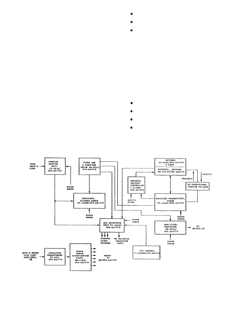
Configuration
The major units of the AN/SPS-67(V)1 and (V)3
radar sets are shown in figure 2-1 and figure 2-2
respectively. As you can see, there is only a slight
difference between the AN/SPS-67(V)1 and the
AWSPS-67(V)3 versions. Think back to the basic
block diagram of a pulse radar in chapter 1 (fig. 1-4).
Relate the function blocks in figure 1-4 to the basic units
shown in figure 2-1. If you understand the basics, you’ll
find that no matter how many special operating
functions a radar has, the basic system is still the same.
The receiver-transmitter and video processor
components of the AWSPS-67(V) bolt to the same
bulkhead foundations used for the AN/SPS-10 series
components. The remaining components mount in the
same area of the units they replace, although they may
or may not have the same shape as the AN/SPS-10
components. The dummy load mounts on the output of
the receiver-transmitter unit.
SIGNIFICANT INTERFACES.— Although
radar systems provide valuable information by
themselves, the interface of that information with other
warfare systems is critical.
The AN/SPS-67(V)1 meets interface requirements
of the following equipment:
Electronic Synchronizer, AN/SPA-42 or
AN/SPG-55B
Blanker-Video Mixer Group, AN/SLA-10( )
IFF Equipment
Indicator Group, AN/SPA-25( ) or equivalent
Synchro Signal Amplifier, Mk 31 Mod 8A or
equivalent
The AN/SPS-67(V)3 meets interface requirements
for the following additional equipment:
Shipboard Emission Monitor-Control Set,
AN/SSQ-82(V) (MUTE)
Data Multiplex System, AN/USQ-82(V)
Signal
P r o c e s s o r C o n v e r t e r G r o u p ,
OL-191(V)5/UYQ-21(V)
Command and Decision System, Mk-2
Gyro Digital Converter, P/O Mk-38/39 and
ACTS Mk-29
Surveillance and Control System, AN/SPY-1
FOR THE MAINTAINER.— The AF/SPS-67(V) is
a solid-state replacement for the AN/SPS-10 radar system.
Miniature and micro-miniature technologies are used
throughout the radar set. It is more reliable and has better
logistical support, with 92 percent of its construction being
Standard Electronic Modules (SEM).
The Built-in-Test (BIT) microprocessor sub-assembly
uses on-line performance sensors to decrease the chance
of operating the radar with an undetected fault. Using BIT
circuitry during normal operation will not degrade system
performance, nor will faulty BIT circuitry affect system
performance. When system failures do occur, you can use
BIT to isolate 95 percent of the possible faults to a
maximum of four modules within the receiver-transmitter
or video processor.
BIT circuitry uses light-emitting diodes (index
indicators) at certain test points to indicate the locations
of faults. The condition of the system at each test point
is displayed on readout indicators as GO, MARGINAL,
or NO-GO. In addition, the BIT subsystem provides an
interactive test mode that permits you to monitor certain
test points while making level or timing event
adjustments. Power and voltage standing wave ratio
(vswr) are monitored on an on-line basis. The BIT
subsystem also automatically tests itself periodically by
going into a self-check mode.
Maintenance
The AN/SPS-67(V) radar set operates continuously
during the ship’s deployment. The responsibility for the
organizational level maintenance falls on the ship’s
Electronics Technicians, (NEC ET-1507.)
Organizational level maintenance consists of
preventive maintenance (PM) and corrective
maintenance (CM). PM is performed according to
maintenance requirement cards (MRCs) developed for
the AN/SPS-67(V) system. PM at this level includes
checks of operational status and filter/equipment
cleaning. CM is performed according to the
AN/SPS-67(V) technical manual procedures, and
includes removing and replacing chassis-mounted piece
parts, modules, assemblies, and sub-assemblies.
R e p a i r a b l e m o d u l e s , a s s e m b l i e s , a n d
sub-assemblies are returned to the depot according to
Navy supply procedures.
AN/SPS-64(V)9
The AN/SPS-64(V)9 radar is a two-dimensional
(2D) navigation/surface search radar used as a primary
radar on small combatants and various non-combatant
2-3
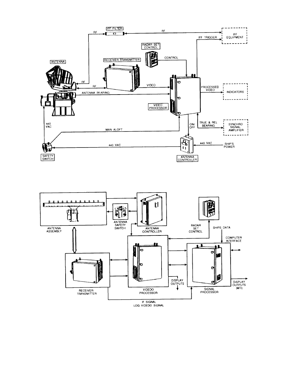
Figure 2-1.—AN/SPS-67(V)1 radar.
Figure 2-2.—AN/SPS-67(V)3 radar.
2-4
ships. It is also used as a back-up radar on large
combatants. It provides a true bearing display for
coastal piloting and a capability for radar navigation and
station keeping.
The AN/SPS replaces a variety of small
commercial radars on the following types of ships:
AE
ASR
C G N F F G
LPH
AGDS ATS CV
LCC LST
A O E A V T
CVN
LHA
MHC
ARL BB
DDG
LHD
MSO
ARS CG FF
LPD
PHM
General Theory of Operation
The AN/SPS-64(V)9 has a minimum detection
range of 20 yards on a radar cross-sectional target of 10
square meters, 3 feet above the surface of the water. It
can operate in either true or relative bearing when used
with Navy gyrocompasses.
Some special operating features of the radar
include:
Ship line voltage protection
Ship Heading Marker (SHM)
Variable range marker
Configuration
Figure 2-3 provides a general overview of how this
radar operates.
Unlike the AN/SPS-67 radars, this
off-the-shelf radar system was not designed to use
existing antennas and indicators. All the components,
including the indicator and the antenna system, are
unique to the AN/SPS-64(V)9.
SIGNIFICANT INTERFACES.— Information
from the AN/SPS-64(V)9 interfaces with the following
Navy equipment:
Blanker/Video Mixer Group, AN/SLA-10
Indicator Group, AN/SPA-25( ) or equivalent
Synchro Signal Amplifier, Mk 27 or equivalent
Mk 19 gyrocompass or equivalent
FOR THE MAINTAINER.— The AN/SPS-
64(V)9 is designed and constructed according to the best
Figure 2-3.—AN/SPS-64(V)9 radar block diagram.
2-5

commercial practices.
For example, there are safety
i n t e r l o c k s o n t h e a n t e n n a p e d e s t a l , t h e
receiver/transmitter (R/T) unit, and the azimuth range
indicator. All the other units include ON/OFF switches
and indicator lights.
Maintenance
The AN/SPS-64(V)9 was purchased as the single,
commercially available, off-the-shelf radar for the
Navy’s Class B1 radar program. Maintenance support,
including documentation, spares, and levels of
maintenance is also an off-the-shelf concept.
Maintenance responsibilities are assigned to an
existing billet and performed by an Electronics
Technician (no specific NEC assigned). Organizational
level maintenance consists of preventive maintenance
(PM) and corrective maintenance (CM). PM is done
according to the maintenance requirement cards
(MRCs). CM consists of (1) adjustments, alignments,
and tests, as described in the technical manual and (2)
replacement of the lowest replaceable unit (LRU)
required to correct radar discrepancies.
The Miniature/Microminiature (2-M) Electronic
Repair Program and the Support and Test Equipment
Engineering Program (STEEP) are not used for the
AN/SPS-64(V)9 radar, since the Navy has no data rights
for the equipment.
M a j o r o v e r h a u l a n d r e s t o r a t i o n o f t h e
AN/SPS-64(V)9 radar and LRU repair are performed at
the depot level, in the prime contractor’s facility.
Technical Repair Standards (TRSs) are not available
since the Navy does not make depot-level repairs.
AN/SPS-55
The AN/SPS-55 is a solid-state, Class A surface
search and navigation radar. It is used to detect small
surface targets and for navigation and pilotage. The
AN/SPS-55 radar detects targets from as close as 50
yards to as far as 50 nautical miles. It was specifically
d e s i g n e d f o r i n s t a l l a t i o n i n t h e f o l l o w i n g
new-construction ship classes:
AO-177
CGN-38 DDG-993 MCM-1
CG-47
DD-963
FFG-7
PBC-1
A radar video converter (RVC) modification was
developed for AN/SPS-55s used on the FFG-61 class.
The AN/SPS-55 radar supports several mission
areas including Antisurface Warfare (ASUW),
Antisubmarine Warfare (ASW), Amphibious Warfare
(AMW), Special Warfare (SPW), Mobility (MOB), and
Command and Control (CAC).
General Theory of Operation
The radar set operates from 9.05 GHz to 10 GHz,
and can tune over the entire bandwidth within 60
seconds. Tuning can be controlled from either the
remote
radar set control (RSC) or the
receiver-transmitter (R/T) unit. The transmitter uses a
magnetron with a minimum peak power of 130 KW.
The receiver can operate in a long-pulse mode (1.0
%sec) or short-pulse mode (.12 %sec) with minimum
ranges of 200 yards and 50 yards respectively. The
antenna consists of two back-to-back end-fed, slotted
waveguide arrays with a scan rate of 16 rotations per
minute (rpm).
Some special operating features of the AN/SPS-55
radar set include:
Squint compensation
Variable sensitivity time control
Fast time constant (FTC)
Log/linear-log intermediate frequency (IF)
amplifier
Video blanking circuit
Sector radiate capability
Automatic and manual frequency control
(AFC/MFC)
The RVC modification provides these additional
features:
Analog/digital (A/D) conversion
Digital integration with beam time interval
Noncoherent DMTI
Moving window constant false alarm rate
(CFAR) thresholding
Segmented CFAR
Configuration
As shown in figure 2-4, the major components of
the AN/SPS-55 radar include the antenna, the
2-6
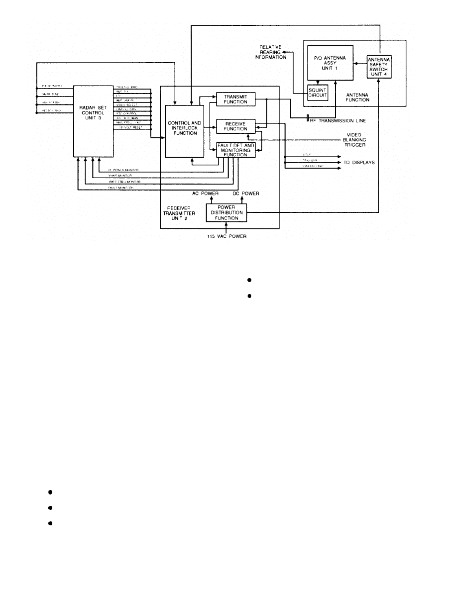
Figure 2-4.—AN/SPS-55 block diagram.
receiver-transmitter (R/T), the radar set control (RSC),
and the antenna safety switch.
Although the AN/SPS-55 radar is electronically
reliable, the antenna pedestal has been a source of
mechanical maintenance problems. A field change kit,
developed in FY89, provided an improved antenna
pedestal.
Delivery and installation of the pedestal
modification are coordinated by the Restoration
Program Manager.
SIGNIFICANT INTERFACES.— The AN/SPS-
55, like all radars, has an impact on other systems,
subsystems, and equipment. The RVC modification
developed for the FFG-61 and the antenna pedestal
modification not only improved the radar set, but
improved the interface capabilities. The RVC enables
the FFG-61 Integrated Automatic Detection and
Tracking System (IADT) to use the AN/SPS-55 data.
The pedestal modification allows interface with IFF.
The AN/SPS-55 interfaces with the following
equipment:
Blanker/Video Mixer Group, AN/SLA-10
Indicator Group, AN/SPA-25( ) or equivalent
Mk 27 synchro signal amplifier or equivalent
Mk XII IFF (pedestal mod only)
AN/SYS-2(V)2 IADT (FFG-61 RVC mod only)
FOR THE MAINTAINER.— The AN/SPS-55
radar has various built-in features to protect the
maintainer and the equipment. The transmitter has a
voltage standing wave ratio (vswr) alarm. Fault
detection indicators, located on both the transmitter and
the RSC unit, show when the high-voltage power
supply, modulator, or magnetron exceeds predetermined
safe limits. A low-power condition in the radar
automatically places the radar in the standby mode and
activates an indicator at the RSC when low power exists.
The antenna safety switch, when activated, opens
the radiate interlock, removing power from the drive
motor. It also activates a “Man Aloft” indicator on both
the R/T and the RSC unit to ensure that no one tries to
operate the radar during maintenance.
Maintenance
Maintenance of the AN/SPS-55 consists primarily
of module replacement, with limited repair or
replacement of certain individual components. The
equipment is designed for rapid fault isolation to the
2-7

lowest replaceable unit (LRU). The technical manual
lists the assemblies and components that can be replaced
during organizational level maintenance.
Electronics Technicians (NEC ET-1491 for FFG-7
Class ships or ET-1504 for all other ships) are
responsible for organizational level maintenance of the
AN/SPS-55. Preventive maintenance (PM) and
corrective maintenance (CM) include:
electrical and mechanical alignments;
adjustments, and calibration;
fault detection, isolation, and module or major
part repair/replacement; and
all correction and verification necessary to
restore the radar set to an operating condition.
Disposition and repair of failed components is
specified by the Source, Maintenance, and
Recoverability (SM&R) codes in the applicable
Allowance Parts List (APL). Send your repairable
modules to the Designated Overhaul Point (DOP) for
repair or condemnation.
AIR SEARCH (2D) RADARS
The two primary functions of air search radar are to
(1) detect aircraft targets at long ranges and (2)
determine their range and bearing. Some of the most
widely used two-dimensional (2D) air search radars in
the Navy are the AN/SPS-37A, AN/SPS-43,
AN/SPS-43A, AN/SPS-49(V), AN/SPS-40B/C/D/E,
and AN/SPS-65(V) aboard ships and the AN/GPN-27
(ASR) at shore installations.
We will not discuss the AN/SPS-29, AN/SPS-37,
and AN/SPS-43 radars, since the AN/SPS-49(V) radar
replaces them.
AN/SPS-49(V)
The AN/SPS-49(V) radar is the primary U.S. Navy
early warning air search 2D radar.
It is a
very-long-range radar, and provides long-range air
surveillance in severe clutter and jamming
environments. It primarily supports the anti air warfare
(AAW) mission on surface ships, but also provides
backup to the 3D weapon system radar. The
AN/SPS-49(V) radar is also used for air traffic control
(ATC), air intercept control (AIC), and antisubmarine
aircraft control (ASAC).
The AN/SPS-49(V) radar replaces the AN/SPS-29,
AN/SPS-37, AN/SPS-40, and AN/SPS-43 radars in
some ships, including the following ship types:
CG
CV
DDG
LHD
CGN
CVN
FFG
LSD
Current planning calls for installation of the
AN/SPS-49(V) radar in 160 U.S. Navy ships, plus
various shore installations.
General Theory of Operation
The AN/SPS-49(V) is a narrow-fan beam radar
developed from a Specific Operational Requirement. It
provides the capability to conduct air search operations
on a previously unused radar frequency. This minimizes
electronic interference between ships and increases the
difficulty for hostile electronic countermeasures
(ECM). The AN/SPS-49(V) provides good bearing
measurements to backup the 3D radar weapons system.
Its narrow beamwidth substantially improves resistance
to jamming.
The coherent side lobe canceler (CSLC) cancels
jamming and interference signals, providing the
AN/SPS-49(V) radar further resistance to jamming and
interference. The DMTI capability enhances detection
of low-flying, high-speed targets.
The AN/SPS-49(V)5 version, which has automatic
target detection (ATD) capability, has even more
sophisticated antijamming features. This version offers
improved clutter suppression and a digital interface to
the AN/SYS-2(V) IADT system. The AN/SPS-49(V)5,
does not cancel non-moving targets as with MTI,
instead it uses the newest development in doppler
processing, Finite Impulse Response (FIR) fibers.
These filters separate radar echo returns into fixed and
moving channels according to their doppler
characteristics. The moving channels contain moving
targets only. The fixed channels contain fixed clutter
and blind speed targets.
Rejection of non-moving
targets recurs at a later point in time in the clutter maps.
The “AEGIS Tracker” modification consists of a
PCB card set integrated into the signal data processor.
It adds an embedded tracker, with direct digital interface
with the AEGIS combat system, to the AN/SPS-49(V)7
radar (installed on AEGIS cruisers). With this
modification incorporated, the AN/SPS-49(V)7
nomenclature changes to AN/SPS-49(V)8.
The digital coherent side lobe canceler (DCSC) is
part of the Medium PRF Upgrade (MPU) modification.
2-8

It improves performance against small targets when
subjected to stand-off jamming.
The modification
primarily replaces the receiver’s sensitivity time control
(STC) with a sensitivity velocity control (SVC). SVC
uses radial velocity and target size information to
“filter” out birds and near-in clutter. It suppresses
these unwanted targets while retaining detection
performance throughout the volume of coverage. The
MPU also aids in reducing reaction time to only two
scans by providing very high-quality velocity
estimates for radar targets.
Configuration
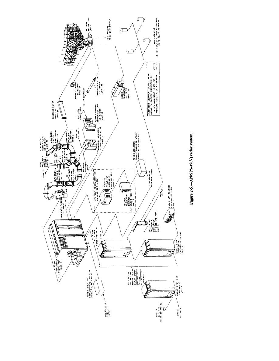
The AN/SPS49(V) radar set contains 47 major
units in nine variant configurations, (V)1 through (V)9.
Figure 2-5 shows the physical configuration of the
AN/SPS-49(V) radar system.
The nine variant configurations are:
(V)1 Baseline radar
(V)2 AN/SPS49(V)1 radar without the
coherent side lobe cancellation
feature
(V)3 AN/SPS-49(V)1 radar with the radar
video processor (RVP) interface
(FC-1)
(V)4 AN/SPS49(V)2 with the RVP
interface
(V)5 AN/SPS-49(V)1 with automatic
target detection (ATD)
(V)6 AN/SPS-49(V)3 without the cooling
system
(V)7 AN/SPS-49(V)5 without the cooling
system
(V)8 AN/SPS-49(V)7 with automatic
detection and tracking (ADT)
(V)9 AN/SPS-49(V)5 with medium PRF
upgrade (MPU)
SIGNIFICANT INTERFACES.— The AN/SPS-
49(V) radar interfaces with shipboard display systems
via conventional radar switchboards and NTDS
switchboards. Field Change 1 provides an optional
interface through the Dual Channel RVP and associated
equipment. In addition, the AN/SPS-49(V)5 version
interfaces with the AN/SYS-2(V) MDT system.
FOR THE MAINTAINER.— Solid-state tech-
nology with modular construction is used throughout the
radar, except for the klystron power amplifier and
high-power modulator tubes. Digital processing
techniques are used extensively in the AN/SPS-49(V)5,
7 and 8.
The radar has comprehensive BIT features, such as
performance monitors, automatic fault detectors, and
built-in-test equipment (BITE). The AN/SPS-49(V)5,
7, and 8 include automatic, on-line, self-test features.
Each major unit has test panels with fault indicators and
test points. There is also a test meter to monitor system
power supply voltage.
Maintenance
The AN/SPS-49(V) radar operates continuously
during deployment.
Radar maintenance is a
responsibility of the ET rating (NEC ET-1503 for
(V)1, 2, 3, 4, and 6 or ET-1510 for (V)5, 7, 8 and 9).
Basic maintenance involves module replacement and
planned maintenance (PM) and follows the policies
s e t f o r t h i n N A V S E A I N S T 4 7 0 0 , 1 a n d
NAVMATINST 4700.4B.
Organizational maintenance consists of PM and CM,
performed on the radar in place, while the ship is
underway. CM is limited to (1) fault isolation, (2) removal
and replacement of modules or cabinet-mounted piece
parts, and (3) the adjustment, alignment, and testing
required to correct the radar degradations. All repairable
modules are shipped to DOP for repair as directed by
SPCC Mechanicsburg.
Removing and replacing the radar antenna and various
major antenna subassemblies require intermediate-level
maintenance. These tasks are conducted as directed by the
NAVSEASYSCOM Restoration Program.
AN/SPS-40B/C/D/E
The AN/SPS-40B/C/D/E is the primary shipboard
long-range, high-powered, two-dimensional (2D), air
search radar. It provides 10-channel operation, moving
target indicator (mti), pulse compression, and high data
short range mode (SRM) for detecting small,
low-altitude, close-in targets. Designed for use aboard
frigate-size or larger ships, the AN/SPS-40B/C/D radar
is used on the following types of ships:
AVT FF CC
CGN
DDG
Field Change 11, which changes the nomenclature
to AN/SPS-40E, replaces the tube-type power amplifier
with a solid-state transmitter (SSTX) and provides a
substantial improvement in operational availability.
The AN/SPS-40E radar is used on the following types
of ships:
AGF
DD
LHA
LPH
AOE
LCC
LPD
LSD
2-9
2-10

The many changes to this radar set have improved
its minimum range capability, as well as made it more
reliable and easier to maintain.
General Theory of Operation
The AN/SPS-40 radar set, with the automation
module, is better able to detect targets over land and
water and to generate clutter-free target data. It has a
two-speed drive motor, which increases the antenna rate
to 15 rpm for high-data rate capabilities and operates at
a normal 7.5 rpm speed in the long-range mode (LRM).
Some special operating features of the
AN/SPS-40B/C/D/E include the following:
DMTI
Long-range, long-range/chaff, and short-range
modes
Automatic target detection (ATD)
Built-in-test (BIT) equipment
Analog/digital conversion
Four-pulse staggered pulse repetition frequency
(prf)
Operator selectable antenna scan rate
Sensitivity time control (STC)
Configuration
Figure 2-6 illustrates the AN/SPS-40B/C/D
DMTI/RVC radar system. The DMTI field change
replaces the analog moving target indicator with more
reliable and more easily maintained digital circuitry. It
also provides a new radar set control (RSC) and replaces
the duplexer with a solid-state unit. The RVC field
change allows the radar to interface with the AN/SYS-1
IADT system.
Installation of the solid-state transmitter, field
change (FC-11 ), replaces 11 shipboard units (units 2, 3,
4, 6, 16, 17, 18, 19, 21, 23, and 25) with five units (units
28 through 32) as shown in figure 2-7.
SIGNIFICANT FIELD CHANGES.— As we
mentioned before, this radar set has had many changes.
Some of the more significant field changes are:
Digital
moving
target
indicator
(DMTI)—solid-state upgrade
Radar video converter (RVC)—interface with
AN/SYS-1
Solid-state transmitter (SSTX)—changes the
number of units in the configuration and the
nomenclature of the system
AN/SPS-40E Field Change 2—changes the
two-cabinet PA configuration to a single cabinet
PA
AN/SPS-40E Field Change 3—replaces the
DMTI with a new coherent receiver processor
SIGNIFICANT INTERFACES.— The An/SPS-
40B/C/D/E interfaces with shipboard display systems
via conventional radar switchboards and NTDS
switchboards. The AN/SPS-40B/C/D/E radar with
DMTI/RVC interfaces with the AN/SYS-1 Integrated
Automatic Detection and Tracking System (IADT).
FOR THE MAINTAINER.— The increased use of
solid-state design and modular construction in the
AN/SPS-40 radar results in a longer mean time between
failures (MTBF) and a shorter mean time to repair
(MTTR). The new receiver and mti both use
built-in-test equipment to help in alignment and
troubleshooting.
Maintenance
The AN/SPS-40B/C/D/E radar is designed for
continuous operation during deployment. The
maintenance responsibilities are assigned to the ET
rating (NEC ET-1516, ET-1508 (with DMTI), and
ET-1511 (with FC-11)). The SPS-40’s modular design
minimizes maintenance actions at the organizational
level.
Organizational maintenance includes preventive
and corrective maintenance.
PM is performed
according to technical manuals and maintenance
requirement cards (MRCs).
CM is performed according to the corrective
maintenance section of the technical manuals and by the
Source Maintainability and Recovery (SM&R) code
assigned in the APL. You may be required to perform
any of the following actions:
Remove and replace cabinet-mounted piece
parts, modules, assemblies or sub-assemblies.
Repair modules, assemblies, or sub-assemblies
designated as shipboard repairable.
Turn in depot repairable items using prescribed
supply procedures.
2-11
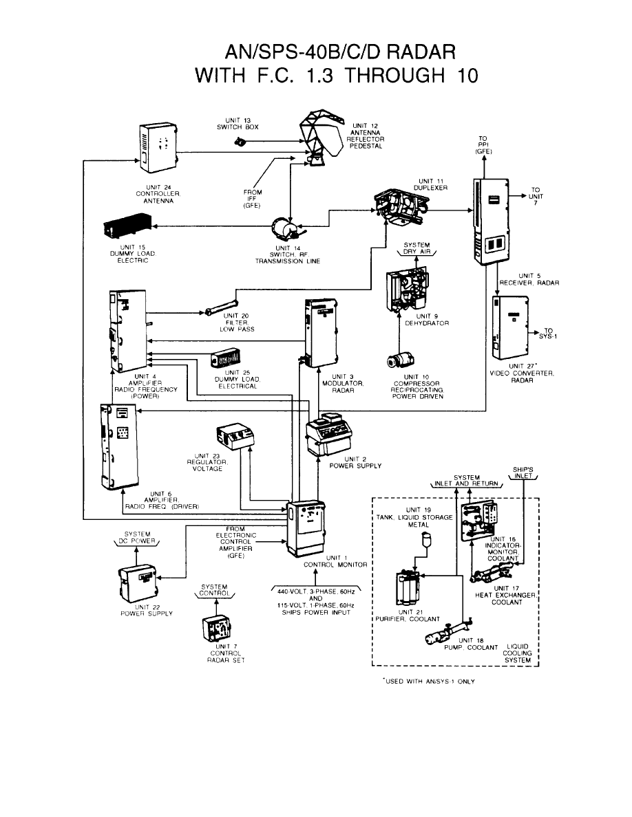
Figure 2-6.—AN/SPS-40B/C/D DMTI/RVC radar system.
2-12
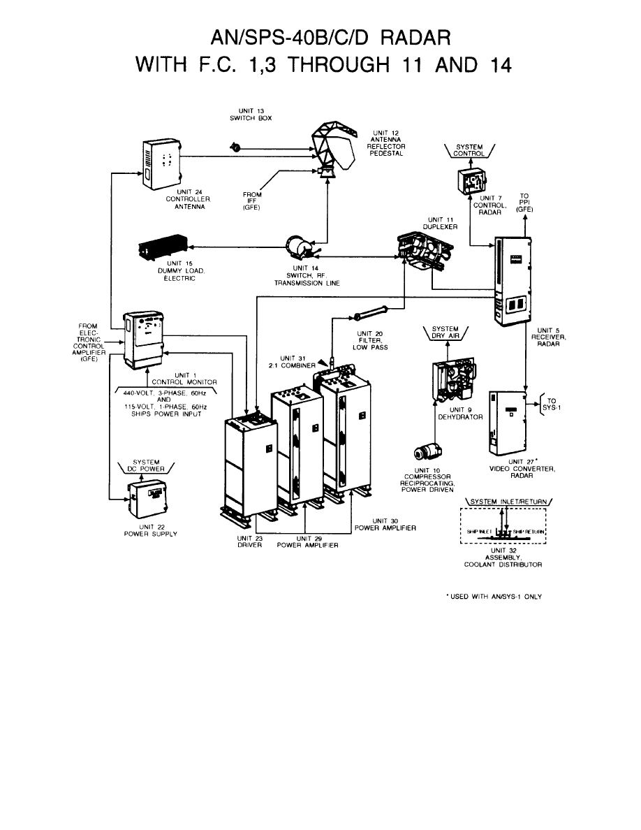
Figure 2-7.—AN/SPS-40E radar system.
System overhaul and restoration are performed on
AN/GPN-27 (ASR-8)
a turn-around basis every 10-15 years by naval
shipyards or private contractors as directed by
The Airport Surveillance Radar AN/GPN-27 is used
NAVSEA. Antenna and pedestal restoration is done on
at naval air stations (NAS) and Marine Corps air stations
(MCAS) to detect aircraft within 60 nautical miles of
a turn-around basis, with the assembly aboard ship
the station and to generate plan position indicator (PPI)
replaced about every 3 years.
information for aircraft control.
2-13

General Theory of Operation
The AN/GPN-27 is a modular, solid-state,
dual-channel, dual-beam/frequency diversity, S-band,
surveillance radar used for safe, efficient movement of
air traffic within the naval or Marine Corps Air Station
National Airspace System area.
Some of the operating features include:
Stable local oscillator (STALO)
MTI with 10-bit design
Clutter rejection
Circular polarization
Reduced side lobes
Field-programmable range azimuth gate
Configuration
The AN/GPN-27 radar includes three major groups:
an antenna group, a transmitter building group, and a
display site group.
The antenna group consists of a reflector, dual-feed
assembly, rotary joint, pedestal, and a dual-drive train
assembly. It is a dual-beam design with normal and
passive channels, including switchable linear and
circular polarization. The cosecant-squared elevation
pattern provides constant radiation altitude coverage up
to 30 degrees above peak of beam. The passive,
receiver-only feed horn is tilted upward from the normal
beam to reduce interference from ground clutter at short
ranges.
In the transmitter building group, the transmitter
has an air-cooled klystron, a solid-state modularized
modulator, and a solid-state, high-voltage power supply.
The receiver provides normal video, log video, and
moving target indicator (mti) video signals to the
processor unit. The digital processor processes the
receiver video for the radar tuning and control circuits,
the range/azimuth gate generator, the azimuth pulse
generator (APG), and the video cable-line drivers. The
system control interface and distribution unit features a
solid-state control system for radar command and status
indications. A 16-inch maintenance plan position
indicator (MPPI) aids in system alignment and
maintenance. The transmitter building group also has
two of the five stations (1 master and 1 slave) of the
intercommunication system.
The display site group at the indicator site or air
traffic control (ATC) room consists of a display site
remote unit, two system control panels, a display site
cable junction box, and an intercommunications system
with three stations (2 master and 1 slave).
SIGNIFICANT INTERFACES.— The only
interfacing is within the system itself. The control
system contains control boxes that have release and
take-control circuitry to ensure that radar command is
available only at the selected control box. Operators
scan the radar screen for incoming and outgoing aircraft,
vector aircraft to the airfield, and work with other
controllers to coordinate precision approach radars
(PAR) and land aircraft.
FOR THE MAINTAINER.— The AN/GPN-27
uses state-of-the-art design and technology. All radar
command and status signals stay in power-protected
solid-state memory, isolating the control system from
short-term power outages. The MPPI at the transmitter
building aids in system alignment and other
maintenance.
Maintenance
Maintenance of the AN/GPN-27 is performed on
demand or as scheduled and is done by Electronics
Technicians (NEC ET-1580). Organizational level
maintenance includes fault isolation, performance
testing, and alignment.
Corrective maintenance
consists of the removal and replacement of
sub-assemblies, modules, and printed circuit boards
( P C B s ) .
Those items not repairable at the
organizational level are returned to the depot facility
through normal Navy supply channels.
THREE COORDINATE (3D) AIR
SEARCH RADARS
Fire Control Technicians (FCs) usually
maintain the height-finding radars installed aboard
Navy ships. So, rather than cover specific
equipment, we will cover general information to
help you understand the overall radar capabilities
of your ship.
The 3D radar functions much like the 2D system,
but also provides elevation information. To do this,
the height-finding radar uses a beam that is very
narrow, both vertically and horizontally. Azimuth is
provided as the antenna rotates continuously at speeds
varying up to 15 rpm. Although the antenna usually
operates in the automatic mode, the operator may
2-14

control it manually for searching in a specific target
sector.
As we mentioned in chapter 1, the air search 3D
radars determine altitude by scanning the vertical plane
in discrete increments (steps). Although this may be
done mechanically, most frequently, it is done
electronically. Figure 2-8 shows the radar beam
radiated at different elevation angles as electronic
scanning changes the radiated frequency in discrete
steps. Each elevation angle or step has its own particular
scan frequency.
A computer electronically synchronizes each
radiated frequency with its associated scan angle to
produce the vertical height of a given target.
The 3D radars also use a range-height indicator
(RHI) in addition to the PPI used with 2D radars. We
will discuss both indicators in further detail in the
section on radar indicators.
CARRIER-CONTROLLED APPROACH
(CCA) AND GROUND-CONTROLLED
APPROACH (GCA) RADARS
C a r r i e r - c o n t r o l l e d a p p r o a c h ( C C A ) a n d
ground-controlled approach (GCA) systems guide
aircraft to safe landings, even under conditions
approaching zero visibility. Radar is used to detect
aircraft and to observe them during their final approach
and landing. Guidance information is supplied to the
pilot in the form of verbal radio instructions, or to the
automatic pilot (autopilot) in the form of pulsed control
signals.
The primary approach systems in the Navy are the
AN/SPS-46(V) Precision Approach Landing System
(PALS) for CCA and the AN/FPN-63 Precision
Approach Radar (PAR) for CGA.
AN/SPN-46(V) PALS
The AN/SPN-46(V)1 system provides safe and
reliable final approach and landing for PALS-equipped
Figure 2-8.—Electronic elevation scan.
carrier-based aircraft, during daylight or darkness. It is
rarely affected by severe weather and sea state
conditions, and is not affected by low ceiling and
visibility problems.
The AN/SPN-46(V)2 system is installed at selected
naval air stations (NAS). It is used for the PALS training
of flight crews, operator and maintenance personnel,
and the PALS certification of aircraft.
The AN/SPN-46(V)1 system replaces the
AN/SPN-42A Automatic Carrier Landing System
(ACLS) on CV/CVN class ships. The AN/SPN-46(V)2
system replaces the AN/SPN-42T1/3/4 at various naval
air stations.
General Theory of Operation
The AN/SPN-46(V) PALS allows simultaneous and
automatic control of two aircraft during the final
approach and landing phase of carrier recovery
operations. Designed primarily as an “automatic”
landing system, it also has manual control capabilities.
The AN/SPN-46(V) has three modes of operation that
are identified, based on the type of control (automatic or
manual) and the source of information (display or
voice).
Mode I (automatic control).—The Central
Computer Subsystem (CCS) processes flight
information from the radar/ship motion sensor (SMS),
wind speed and direction equipment, and other ancillary
equipment. It then transmits command and error signals
to each aircraft via the Link 4A. The aircraft receives
these command and error signals and translates them
into control actions that maintain the aircraft within a
narrowly prescribed flight envelope.
Mode II (manual control with display).—The
aircraft cockpit display receives command and
error signals that direct the pilot to take proper
actions.
Mode III (manual control with voice).—The air
traffic controller, using the processed flight data
transmitted to the operator control console (OCC),
provides the pilot with voice communications for a
manual approach.
Configuration
The AN/SPN-46(V)1 system consists of 26 units
categorized into four major subsystems: display
(units 1 and 2), ancillary equipment (units 3-11),
central computer (units 12- 16), and radar/SMS (units
17-26). A pictorial flow diagram of the system is
2-15

shown in figure 2-9. The AN/SPN-46(V)2 functions
the same as the AN/SPS-46(V)1, except that it does
NOT use the MK 16 Mod 12 stable elements (units 17
and 18). Also, the (V)2 uses a 7-foot diameter antenna
instead of the 4-foot antenna used for the (V)1.
The display subsystem consists of two identical
operator control consoles (OCC) (units 1 and 2), one for
each channel of the system. The OCCs allow the final
controllers to control and monitor the AN/SPN-46(V)
system. The OCC includes a radar display, a data
generator, and an embedded computer. The OJ-314
system installed in the OCC provides operator
communications.
The ancillary equipment subsystem includes
aircraft control indicators (units 4, 6, and 7) for the
Carrier Air Traffic Control Center (CATCC) and
Primary Flight (PRI-FLI) areas. The PRI-FLI
indicators (units 6 and 7) display the flight information
and system status required for each OCC. The
recorder-converter (unit 8) records selected system data.
The landing signal officer (LSO) waveoff light (unit 10)
provides the LSO with a visual indication of the system
waveoff on the nearest aircraft under control.
The central computer subsystem (CCS), consisting
of two identical AN/AYK- 14(V) computer sets, receives
data from the radar/SMS and OCCs. It computes
aircraft command and error signals and transmits them
to controlled aircraft via Link 4A.
The radar/ships motion sensor (SMS) subsystem
consists of two radar channels, each with an X-band
receiver, a K
a
-band transmitter, and an antenna. It
consists of several units, including the receiver and
antenna (units 24 and 25), Mk 16 stabilization elements
(units 17 and 18), and embedded computer processors
(unit 19). Aircraft tracking information (from the radar)
combines with ship’s stabilization data (from the Mk 16
gyros) and goes to the CCS for processing.
SIGNIFICANT INTERFACES.— The digital
data switchboard (unit 14) provides an automatic
switching interface between the master-slave computers
in the central computer group (unit 12) and all external
system peripherals required for PALS operation. The
AN/TPX-42A(V)8 CATCC DAIR, AN/SSW-1C/D, and
OA-7984(U)/UYK Input/Output (I/O) Control Console
(unit 16) can all operate as the master computer of the
CCS. Electrically operated switches automatically
switch these equipment into a master or slave
configuration in the central computer group. The
AN/SPN-46(V) also interfaces with the
AN/TPX-42(V)8 system through the power distribution
panel (unit 3).
Other radars, such as the AN/SPN-35, the
AN/SPN-43, and the AN/SPN-44, are also used in
conjunction with the precession carrier controlled
approach (CCA) system for landing operations.
AN/SPN-35.— The AN/SPN-35 radar set provides
both azimuth and elevation data for precision
approaches to aircraft carriers during adverse weather
conditions. Using the radar display, the operator directs
pilots along a predetermined glide path and azimuth
courseline to a point one mile from the ship.
AN/SPN-43.— The AN/SPN-43 is a surveillance
and air traffic control radar used on carriers and
amphibious-type ships.
It operates in a 2-4 GHZ
frequency band (S-Band) and provides air navigational
data for control and identification of aircraft in the area
of the ship. With a range of 50 nautical miles, it tracks
low-flying aircraft to a minimum of 250 yards and
covers 360° at altitudes from radar horizon to 30,000
feet. The radar displays azimuth and range which the
operator uses to direct control of the aircraft to the CCA
transfer point. An IFF system, synchronized with the
radar, provides positive identification of the aircraft.
AN/SPN-44.— The AN/SPN-44 is a range-rate
radar set that computes, indicates, and records the speed
of aircraft making a landing approach to the carrier.
Both true and relative air speed are indicated. Supplied
with this accurate information on the speed of the
approaching aircraft, the LSO can wave off those
attempting to land at an unsafe speed.
FOR THE MAINTAINER.— The AN/SPN-46(V)
is a modernized PALS system that provides improved
reliability, maintainability, and performance. It uses
standard electronic modules (SEMs), an AN/USH-26
Magnetic Tape Unit (MTU) and standard computers
(AN/AYK-14) to provide reliability and improved
supply support.
The AN/SPN-46(V) has a self-monitor capability to
prevent the transmission of erroneous control and error
signals in Mode I and Mode II operation. It also displays
the deck status.
The power distribution panel (unit 3) provides
circuit breaker protection and acts as a junction box for
all stabilization source inputs and outputs, and
anemometer inputs. The PRI-FLI indicator control
(unit 5) contains circuit breaker protection for PRI-FLI
indicators (units 6 and 7) and a maintenance intercom
for troubleshooting purposes. The recorder-converter
2-16
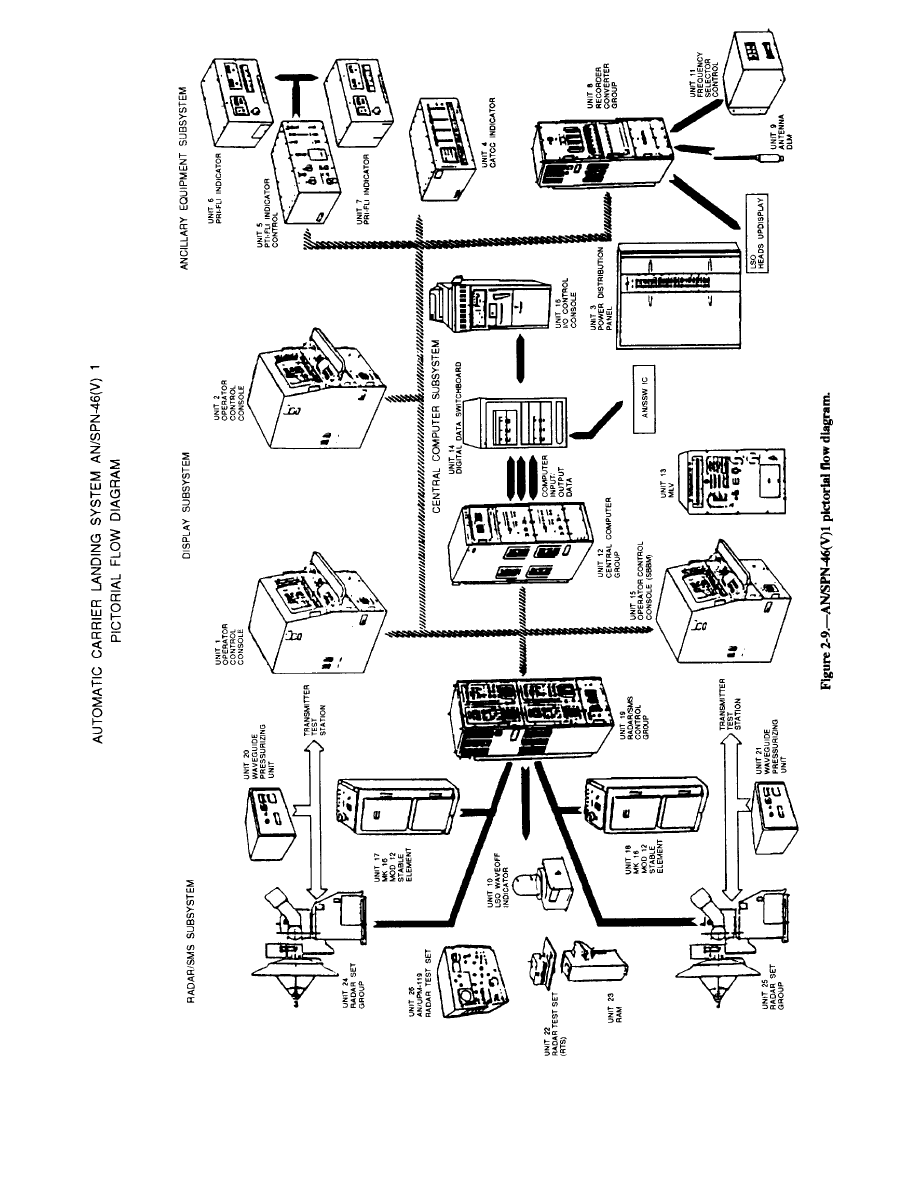
2-17

group (unit 8) has a synchro test point panel to monitor
input synchro voltages.
The OCC installed in the equipment room (unit 15)
is a system/bootstrap bus monitor (SBBM) that
performs on-line system testing and troubleshooting,
and computer bootstrap program loading. The memory
loader/verifier (MLV) (unit 13), stored in the equipment
room, is used for the following purposes:
Load and verify operational programs from
cassettes
Initiate AN/AYK-14 self-test and display results
Load diagnostics and provide maintenance
interface and control
Write cassette memory with received data
Display and change register and memory
locations
The SPN radar test set (RTS) (unit 22) is used to
align, calibrate, and maintain the radar/SMS subsystem.
The retractable alignment mast (unit 23) elevates the
SPN RTS and a collocated corner reflector to a
minimum of 19 feet above the carrier flight deck for
system calibration. The UPM radar test set (unit 26) is
also used to test and calibrate the radar/SMS subsystem.
This test set combines the functions of a spectrum
analyzer and synchroscope to provide pulse or CW test
signals and visual spectrum indication. It also has a
direct reading cavity frequency meter, and a power level
meter.
Maintenance
Organizational maintenance is performed by ET
personnel (NEC ET-1524). It consists of removal and
replacement of plug-in assemblies and chassis-mounted
parts.
Y o u c a n i s o l a t e f a u l t s u s i n g t h e
built-in-test (BIT), built-in-test equipment (BITE),
general-purpose electronics test equipment (GPETE),
special-purpose test equipment (SPETE), and
maintenance assist modules (MAM).
Depot level maintenance includes repair of failed
printed circuit boards (PCBs) or modules and major
repairs, such as overhaul, refurbishment, and
calibration.
AN/FPN-63 PAR
The AN/FPN-63(V) Precision Approach Radar
(PAR) is used at naval air stations (NAS) and Marine
Corps air stations (MCAS) for air traffic control
operations.
It replaces the PAR portion of the
AN/CPN-4 family of equipment. The AN/MPN-23 is a
version of the same equipment mounted on a trailer.
General Theory of Operation
Although the AN/FPN-63(V) is functionally and
operationally similar to the PAR portion of the
AN/CPN-4, it uses a modified version of the
AN/CPN-4A PAR antenna system. The antenna
modifications reduce signal side lobes and minimize
ground and precipitation clutter. The AN/FPN-63(V) is
based on solid-state circuitry and includes a digital
moving target indicator (mti). The modification also
includes a remote control subsystem that provides
complete operational use of the PAR up to 10,000 feet
from the radar van.
The solid-state AZ-EL range indicator generates its
own internal map, sweeps, range marks, and cursors. A
single curser adjustment allows alignment of each
curser with the runway centerline.
Independent transmitters and receivers provide one
operational channel and one “hot standby” channel.
This allows the operator to use one set of equipment,
while a technician performs maintenance on the other
set. Thus, service is never interrupted.
Configuration
A remote control turntable unit and the associated
remote control panels allow positioning of the radar for
multiple runway operation.
Stations not requiring
multiple runway operation use a fixed-mounted
AN/FPN-63.
All radar components are in racks and enclosures of
the radar sets, with empty spaces covered by blank front
panels. The number of indicators varies by site.
Maintenance
Organizational maintenance is performed by ET
personnel (NEC ET-1579) and includes performance
verification, testing, alignment, and fault isolation.
Repair of equipment consists of the replacement of
discrete chassis components and piece parts.
The prime contractor performs all depot-level
maintenance. If you have any modules or PCBs that
your organization cannot repair, return them to the depot
facility.
2-18

RADAR INDICATORS (REPEATERS)
The purpose of a radar indicator (repeater) is to
analyze radar system echo return video and to display
that information at various remote locations. For the
repeater to present correct target position data, it must
have three specific inputs from the radar selected: video
input, trigger (timing) pulses, and antenna information.
A video input from the radar via a video amplifier
for each returning echo enables the repeater to display
detected targets.
Trigger (timing) pulses from the radar ensure that
the sweep on the repeater starts from its point of origin
each time the radar transmits. This allows repeaters to
display the target at actual range from the radar based
on the time lapse between the instant of transmission and
the instant of target echo receipt.
Antenna information from the radar allows the
angular sweep position of the repeater to be
synchronized with the angular position of the radar
antenna. This will produce and display the target at its
actual bearing (azimuth) from the radar.
The three most common types of displays are the A
scope (range-only indicator), the PPI scope
(range-azimuth indicator), and the RHI scope
(range-height indicator). The A scope, limited by its
range-only capability, is normally considered an
auxiliary display rather than a radar repeater. The PPI
scope is by far the most used radar repeater.
PLANNED POSITION INDICATOR (PPI)
The PPI is a polar-coordinate display of the
surrounding area with the origin of the sweep (normally
located at the center of the screen) representing your
radar. The PPI uses a radial sweep pivoting about the
center of the presentation, resulting in a maplike picture
of the area covered by the radar beam. A relatively
long-persistence screen is used so targets will remain
visible until the sweep passes again.
Bearing is indicated by the target’s angular position
in relation to an imaginary line extending vertically from
the sweep origin to the top of the scope. The top of the
scope represents either true north (when the radar is
operating in true bearing), or ship’s head (when the radar
is operating in relative bearing).
To allow a single operator to monitor several tactical
data inputs from one location, many radar repeaters are
being replaced with multipurpose consoles on Naval
Tactical Data Systems (NTDS) equipped ships.
However, radar repeaters still serve as a back-up to the
consoles used on NTDS ships and are irreplaceable on
non-NTDS ships.
The most common radar indicator group used in the
Navy is the AN/SPA-25G. This Radar Display and
Distribution System usually includes the AN/SPA-25G
Indicator, the CV-3989/SP Signal
the SB-4229/SP Switchboard.
AN/SPA-25G Indicator Group
Data Converter, and
The AN/SPA-25G Indicator Group is found on 90
percent of all Navy ships. It meets the diverse mission
requirements of antiair warfare, antisurface warfare,
antisubmarine warfare, electronic warfare, strike and
amphibious warfare, as well as navigation and bridge
requirements such as piloting and station keeping. The
AN/SPA-25G will replace the AN/SPA-4, SPA-8,
SPA-25, SPA-33, SPA-34, SPA-40, SPA-41, and
SPA-66. The AN/SPA-50 and SPA-74 radar display
system/indicator groups are also potential candidates
for replacement by the AN/SPA-25G.
The AN/SPA-25G is an advanced, solid-state
(except the CRT display) radar indicator for both
Combat Information Center (CIC) and bridge
environments.
It can receive multiple data inputs,
including three radar video signals from the same radar,
radar triggers, antenna synchro data, external course and
speed, off-centering inputs, and dead reckoning
analyzer (DRA) inputs.
The various radar inputs, except video that is in
analog form, are in the Radar Display and Distribution
Systems (RADDS) serial 64-bit data stream format.
The data is continually processed through five
megabits of digital memory. By correlating the radar
data with internally generated graphic symbols, the
operator can fully interact with the displayed
information on the CRT. Figure 2-10, the
AN/SPA-25G top panel layout, shows all of the
operational controls and indicators.
Some of the significant design features of the
AN/SPA-25G include:
High Definition Raster Scan Display-enables
the AN/SPA-25G to perform at maximum capacity,
without a hood, in either the subdued lighting of CIC or
the bright daylight on the ship’s bridge.
Flicker Reduction—provides an effective
display refresh rate that suppresses flicker in any
lighting environment.
2-19
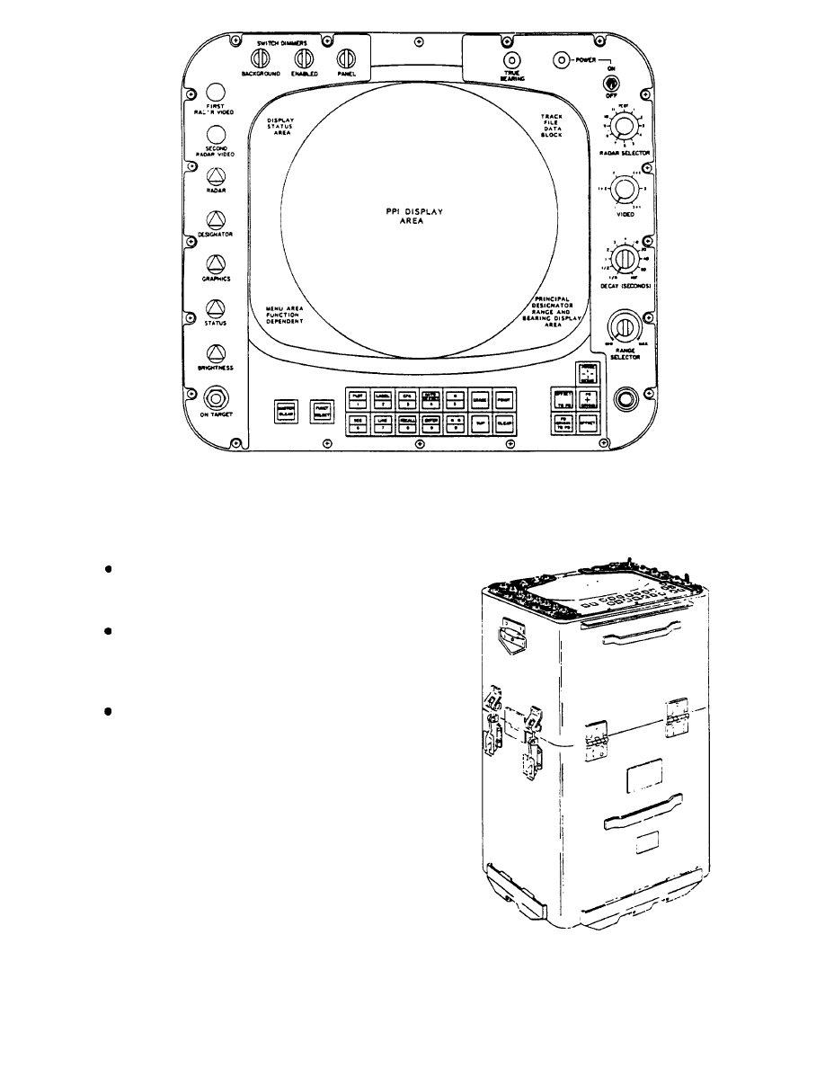
Figure 2-10.—AN/SPA-25G radar indicator, top panel controls and indicators.
Azimuth Fill process—prevents voids, gaps, and
holes in the radar video that occur when translating from
rhotheta to X-Y format.
Electronic Bearing Circle—around the perimeter
of the radar video display, has bearing markers
displayed every 5°, and is numerically labeled every
10°.
Electronic Plotting Aid—provides a continuous
display of ship’s speed and course, offset settings,
principal designator range and bearing, and BIT
message.
Figure 2-11 shows the physical configuration of the
AN/SPA-25G. It has the same form and fit as previous
indicator group models in the AN/SPA-25 series. It will
pass through a
25-inch diameter hatch without
disassembly. If a tilted panel or sit-down console is
required, a 60° insert section and an attachable front
shelf are available (fig. 2-12).
The AN/SPA-25G has unlimited operational
capabilities, since it will interface with any Navy
conventional search radar system. The CV-3989/SP
Figure 2-11.—AN/SPA-25G stand-up configuration.
2-20
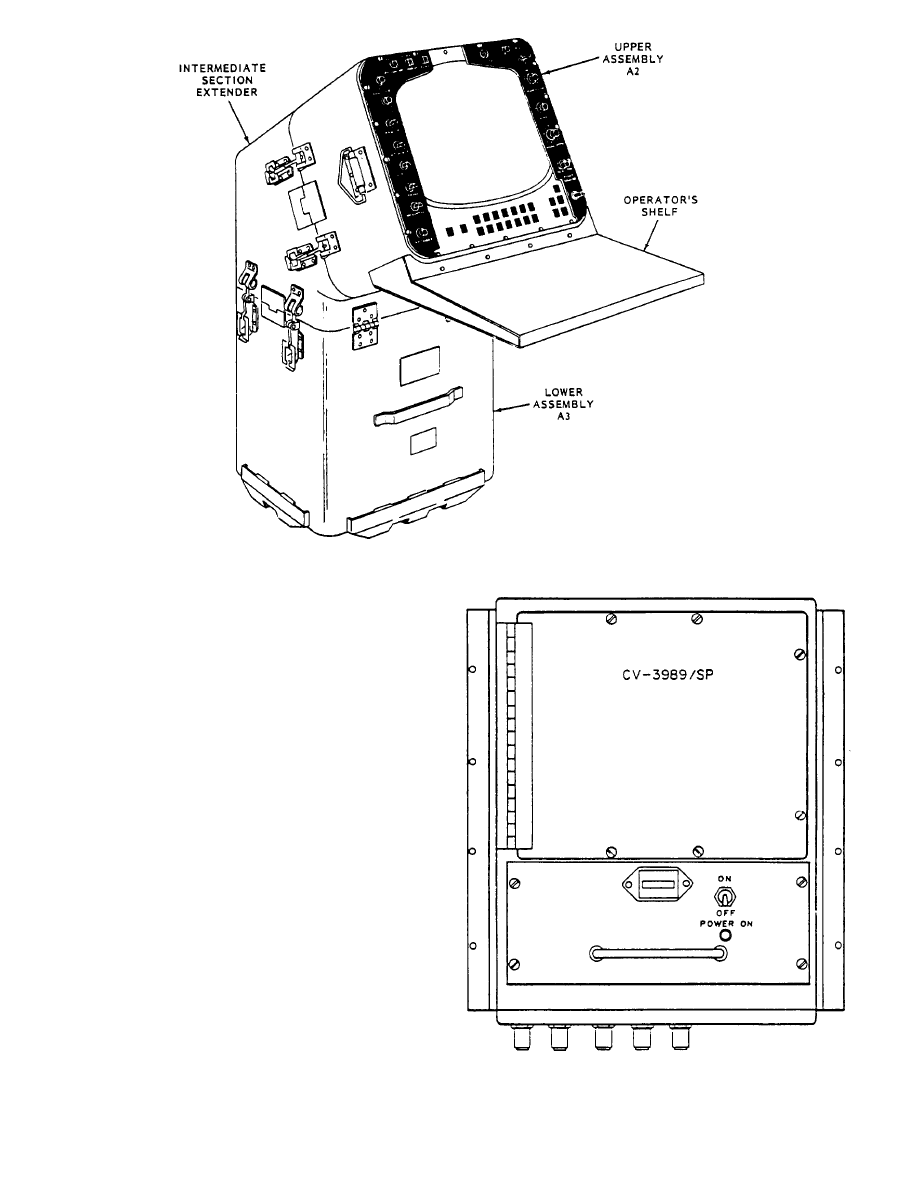
Figure 2-12.—AN/SPA-25G with insert section.
Signal Data Converter provides the primary interface
between conventional equipment by multiplexing
analog information into a single digital data stream for
use by the AN/SPA-25G.
The AN/SPA-25G allows the maintainer to localize
faults quickly by using built-in-test (BIT) and test
messages for circuit and module checkout.
CV-3989/SP Signal Data Converter
The Signal Data Converter CV-3989/SP (SDC),
shown in figure 2-13, is designed for installation inside
the shipboard radar room. It is mated to the radar
(triggers), antenna azimuth, ship’s gyro-heading, and
ship’s speed or distance (ship’s pit log).
The SDC conditions and multiplexes the various data
inputs into a single digital data (RADDS) stream. This
permits a single cable to distribute RADDS stream data
throughout the ship. Previous distribution of radar and
navigation data required multiple cables. The SDC
accepts radar and navigation inputs and converts them into
five independent serial digital data (RADDS stream)
outputs. Over a single coaxial cable, the following data is
provided by the SDC RADDS data stream:
Figure 2-13.—Signal Data Converter, CV-3989/SP.
2-21
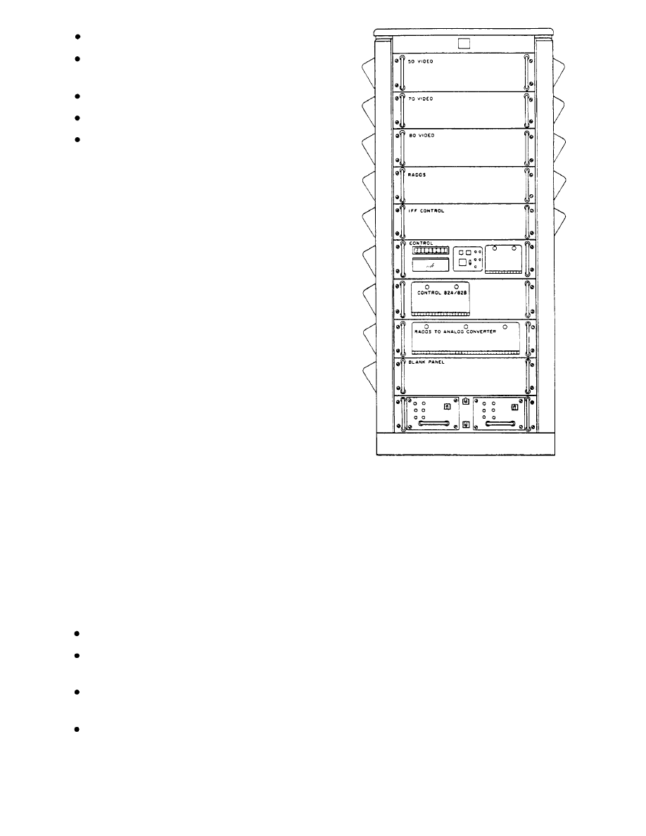
Radar trigger(s)
Radar antenna azimuth (stabilized and
unstabilized)
Dead reckoning information
Ship’s heading
Radar set sensor ID
The SDC also contains the necessary circuitry for
future growth and expanded use in data distribution. A
compatible switchboard is required to interface the data
from various radar sets with other systems.
SB-4229/SP Switchboard
The SB-4229/SP switchboard, shown in figure
2-14, replaces all SB-440, SB-1109, and SB-1505
switchboards. It provides selectable distribution of data
from any Navy conventional search radar set. The
CPU-controlled switchboard can accept signals from 16
radar sets and five IFF interrogator sets, then distribute
them to nine individual radar indicators and nine IFF
decoders. It can also accept mode control from any IFF
decoder associated with any of the radar indicators and
switch the mode control of the IFF interrogator
associated with the radar set being viewed on that
indicator. This process is explained in more detail in
chapter 3.
The SB-4229/SP switchboard allows radar and IFF
signals from ship’s radar and RADDS data stream inputs
to be selected from up to 16 signal data converters. It
provides up to nine selectable outputs to the AN/SPA
series radar indicators. So, up to nine different operators
can select one of 16 input sensors to display at their
indicator. Each of the 16 input sensors can consist of
three radar videos, RADDS data stream, and IFF control
with its associated videos. The more significant design
features include:
Local or remote selection of input sensors
Conversion of RADDS data stream back to
analog (for older indicators)
Distribution of any of the 16 input sensors to any
of up to nine separate radar indicators
Detection of improper operation by self-test
(BIT)
Figure 2-14.—Radar Distribution switchboard, SB4229/SP.
Maintenance
The maintenance of the AN/SPA-25G, CV-3989/SP,
and the SB-4229/SP is performed by the Electronics
Technician (ET) assigned maintenance responsibilities
for the surface search radar or conventional radar
display and distribution systems.
Organizational maintenance consists of corrective
and preventive maintenance actions. Preventive
maintenance is performed according to the maintenance
requirement cards (MRCs).
Shipboard personnel perform corrective
maintenance according to the corrective maintenance
sections of the applicable technical manuals and as
reflected by the maintenance code assigned in the
equipment APL.
CM may require (1) removal or
replacement of cabinet mounted piece parts, (2)
2-22
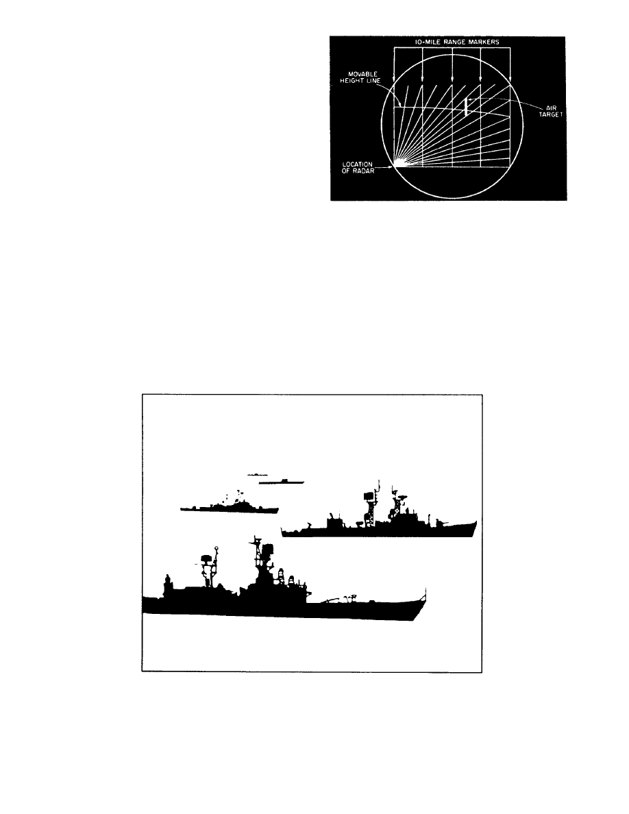
replacement of components, assemblies, or
sub-assemblies, or (3) repair of certain units, assemblies
or sub-assemblies designated as “shipboard repairable.”
It may then require “turn in” of depot repairable
assemblies or sub-assemblies through prescribed supply
procedures.
All replaceable modules, assemblies or printed
circuit boards with a replacement value of $500 or more
(except the CRT and high-voltage power supplies) are
designed and constructed to be repairable by component
replacement at the depot maintenance level.
RANGE-HEIGHT INDICATOR (RHI)
The range-height indicator (RHI) scopes used with
height-finding radars obtain and display altitude
information. The RHI is a two-dimensional
presentation showing target range and altitude. An
example of a RHI presentation is shown in figure
2-15.
The sweep of a RHI starts in the lower left side of
the scope and moves across the scope to the right at an
angle that is the same as the angle of transmission of the
height-finding radar. The line of sight to the horizon is
indicated by the bottom horizontal line.
The point
Figure 2-15.—RHI presentation.
directly overhead in the sky (the zenith) is straight up
the left side of the scope. Targets are displayed as
vertical blips. Vertical range markers are provided to
estimate target range.
The operator determines altitude by adjust-
ing the moveable height line to the point where
it bisects the center of the target blip. Target
height is then read directly from altitude dials
(counters).
2-23

SUMMARY
In chapter 1, you reviewed the basics of the theory
of radar operation. In this chapter, you learned some
basics about specific equipment used in the fleet.
You now know which missions, on what types of
ships, are supported by surface search and navigation
radars, such as the AN/SPS-67(V), the AN/SPS-64(V)9,
and the AN/SPS-55. You are aware of some of the
special operating, maintenance, and safety features of
these radars. You can identify, during troubleshooting,
which systems they interface with.
You learned the same types of things about the 2D
air search radars used by the Navy, such as the
AN/SPS-49(V), the AN/SPS-40B/C/D/E, and the
AN/SPS-65(V) aboard ships and the AN/GPN-27
(ASR) at shore installations. These are air search radars
that you will maintain.
Although the FCs will usually maintain the 3D
radars aboard your ship, you must understand how they
operate in the scheme of the overall radar mission.
Knowledge of carrier controlled approach and
ground controlled approach radar systems such as the
AN/SPN-46(V) and the AN/FPN-63 is essential in the
high-tech warfare we use today. Successful air strikes
and air cover are the key to any military victory.
Multipurpose consoles are replacing many of the
radar repeaters on Naval Tactical Data Systems (NTDS)
equipped ships.
But, radar repeaters still serve as a
back-up to the consoles used on NTDS ships and are
irreplaceable on non-NTDS ships. So, it is still
necessary that you know radar information is provided
by displays such as radar indicators. The A scope
(range-only indicator) is used primarily by the
maintenance personnel to evaluate the operation of the
radar. The PPI scope (range-azimuth indicator) is the
most commom usually consisting of a Radar Display
and Distribution System, including the AN/SPA-25G
Indicator, the CV-3989/SP Signal Data Converter, and
the SB-4229/SP switchboard.
The RHI scope
(range-height indicator) is used with height-finding
radars to obtain and display altitude information.
The Handbook for Shipboard Surveillance Radars,
NAVSEA SE 200-AA-HBK-010, provides information
on radar fundamentals and “rules of thumb” to the level
that will allow you to interpret technical specifications
and performance statements with respect to radar
performance requirements. This is a good publication
to review if you want to make a suggestion for
improvement or modification to a radar system. This
handbook provides technical support and back-up data
for shipboard radar systems engineers. However, it also
provides fundamental and descriptive information for
Navy radar users, including radar principles and
shipboard surveillance radar characteristics.
In chapter 3, we will discuss some of the systems
that use radar information. We’ll discuss the equipment
involved with IFF and DAIR, and also look at some of
the unique maintenance concepts of the Navy Tactical
Data System (NTDS).
2-24

CHAPTER 3
RADAR SYSTEM INTERFACING
In the previous chapters, we discussed a basic pulse
radar system, basic types of radar sets and specific radar
equipment used in the fleet. Most every radar we’ve
mentioned can interface with other systems. In this
chapter we’ll look at some of the systems that use that
radar information, such as Identification Friend or Foe
(IFF) systems, Direct Altitude and Identity Readout
(DAIR) systems, and Navy Tactical Data Systems
(NTDS). We will not teach you specific equipment, but
will help you identify and understand the interface of
radar information with the various systems used in the
Navy today.
Most of the equipment discussed in this chapter has
specific maintenance training available. However,
except for certain crypto equipment, you do not need
specific training to work on the gear. Remember, as an
ET, you can become an expert maintainer of ANY
electronic equipment.
The first system we’ll talk about is Identification
Friend or Foe (IFF) equipment, specifically, the AIMS
Mark XII IFF system, used by aircraft and surface
vessels.
IDENTIFICATION FRIEND OR FOE
(IFF) SYSTEMS
IFF equipment, used with search radars, permits
automatic identification of targets before they are near
enough to threaten the security of a friendly craft. In
addition to friendly identification, modern IFF systems
also provide other information such as type of craft,
squadron, side number, mission, and aircraft altitude.
GENERAL THEORY OF OPERATION
IFF completes the identification process in three
basic steps: (1) challenge, (2) reply, and (3) recognition.
Challenge
The IFF interrogator sends a coded challenge in the
form of pulse pairs. The selected mode of operation
determines the spacing between the pulses.
Reply
A friendly target’s IFF transponder will
automatically reply to the coded challenge with an
omnidirectional transmission. It sends a different set of
pulses at a slightly different frequency than the
interrogator frequency. A suppression (blanking) signal
keeps your ship’s transponder from replying to its own
interrogator.
Recognition
The IFF interrogator receives the coded reply and
processes it for display on an indicator. Recognition of
the target is based on the ppi display. The coded reply
from a friendly craft normally appears as a dashed line
just beyond the target blip, as shown in figure 3-1.
The identification process uses two sets of IFF
equipment, the interrogator set and the transponder set.
A ship may have one or more interrogator sets, but will
have only one transponder set. Normally, interrogators
and transponders aboard ships function independently.
Interrogator
The IFF interrogator operates like a radar
transmitter and receiver. It uses a small directional
antenna either attached to or rotated in synchronization
with the air search radar antenna. The modulator of the
search radar set provides synchronization triggers for
the IFF interrogate.
When processing replies for display, the IFF
interrogator uses the time lapse between the
transmission of a challenge and the reception of a reply
to determine range.
The synchronized antenna
information provides the correct bearing.
A high output power is not required for the one-way
trip to the target taken by the transmitted pulses, so the
IFF interrogator can operate at low peak power (1 to 2
kilowatts).
Transponder
The IFF transponder is a receiver-transmitter
combination that automatically replies to a coded
3-1
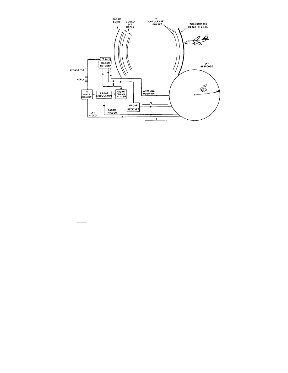
Figure 3-1.—Fundamentats of IFF operation.
challenge. The receiver section receives and amplifies
signals within its bandpass and decodes the challenge
signals. Reception of correctly coded challenge signals
will automatically key the transmitter section to send
prearranged reply signals on a different frequency.
In times of hostility, safe or unsafe transit through a
particular area could depend on how well your IFF is
operating. It’s not very safe to approach another ship in
a hostile area without being able to identify yourself as
a friendly target. Also, being without an IFF that can
identify the targets on your radar screen puts your
Tactical Action Officer (TAO) at a disadvantage.
Therefore, your understanding of IFF operation and
maintenance is extremely important.
AIMS MARK XII IFF SYSTEM
AIMS is an acronym for an air traffic control radar
beacon system (ATCRBS), identification friend or foe
(IFF), Mark XII system. ATCRBS designates the
civilian air traffic control system used for air control
worldwide. IFF identities military systems. The AIMS
system includes equipment such as interrogators,
transponders, decoders, interrogator side lobe
suppression (ISLS) switches and drivers, defruiters, and
crypt computers.
Modes of Operation
The Mark XII system can challenge in five different
modes (1, 2, 3/A, 4, and C), each with a specific
function. The video decoder unit, associated with a
specific indicator, provides control signals that the
interrogator uses to send challenges and decode replies
in the various modes. As we mentioned in chapter 2,
when the operator has multi-radar inputs available, the
radar distribution switchboard routes the control signals
to the correct interrogator unit.
SIF MODES.— Air traffic control and code
monitoring for friendly aircraft and surface craft use
selective identification feature (SIF) modes (modes 1,
2, and 3/A). Challenges in these modes consist of two
pulses spaced at a characteristic interval for each pulse,
with a third pulse added for ISLS operation, as shown
in figure 3-2.
For SIF modes, the transponder reply is a binary
code contained between two bracket (framing) pulses.
Framing pulses are present in every reply, regardless of
code content. Each reply code corresponds to a unique
4-digit decimal code. For each mode, the user dials the
desired reply code into the transponder using
thumbwheel switches. Mode 1, 2, 3/A, and C replies,
by themselves, cannot be separated according to mode.
The interrogator, knowing in which mode it has
challenged, separates and identifies the replies with the
proper mode.
3-2
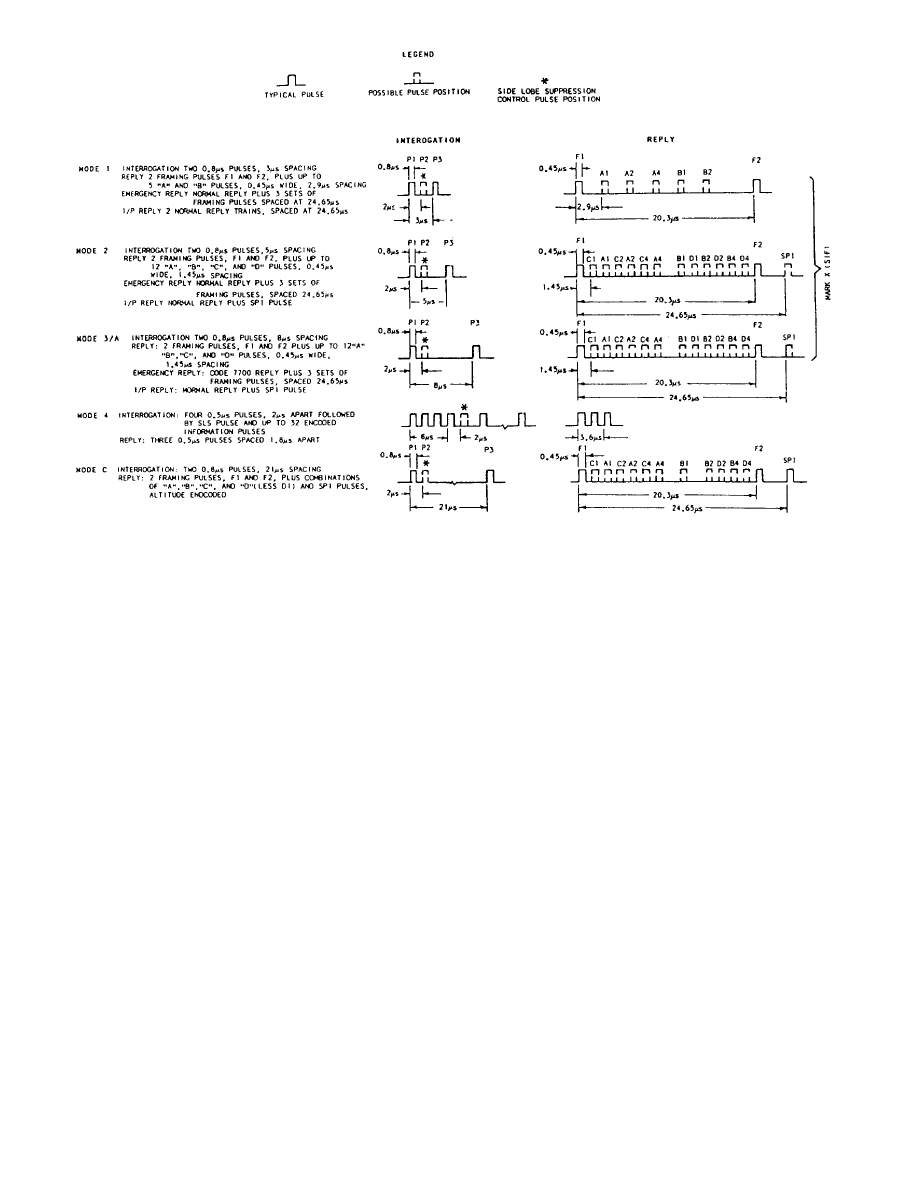
Figure 3-2.—AIMS Mark XII IFF interrogations and replies.
When desired, a transponder may send an
identification of position (I/P) reply to mode 1, 2, or 3/A
interrogations. This reply, when decoded, marks on the
indicator a particular aircraft with which the system
operator has voice communications.
A pilotless aircraft containing a transponder
transmits an X-pulse reply when responding to SIF
mode interrogations. This is a normal mode reply with
an additional pulse occupying the center position of the
reply train.
Mode 1.— Mode 1 operation, set at the control box
C-6280, is for military use only. The first digit of the
reply code must be a number from 0 to 7. The second
digit must be a number from 0 to 3. The remaining two
digits will normally be 0. Military emergency replies
(called 4X or four train emergencies) include the normal
reply plus 3 sets of framing pulses for both modes 1 and
2.
Mode 2.— Mode 2 operation, set in at the
transponder unit, is also for military use only. In mode
2 and 3/A reply codes, each of the four reply digits can
have any value from 0 to 7.
Mode 3/A.— Mode 3/A operation, also set at the
control box, is available for military or civilian use.
Mode 3/A military emergency replies consist of a
combination of 4X and 7700 codes. Civilian emergency
replies use just the 7700 code. A 7600 reply code, for
both military and civilian use, indicates a failure in radio
communications.
A 7777 reply code is assigned to
interceptors on active air defense missions. Any
transponder sending replies to mode 3/A with codes of
7500, 7600, 7700, or 7777 will trigger an alarm at nearby
FAA towers.
The FAA’s nationwide computer network tracks all
assigned mode 3/A codes. The Department of Defense
is assigned four mode 3/A code blocks (50XX, 54XX,
61XX, 64XX) for use within U.S. national air space.
A conflicting signal from your ship could cause
havoc for both local and national air control functions.
The mode 3/A code assigned to your unit during an
operation is probably not a code authorized for military
use in national airspace. It may even be the same as one
assigned to a commercial flight. To avoid problems with
air control, keep mode 3/A off the air when your ship is
in port or coastal waters.
3-3
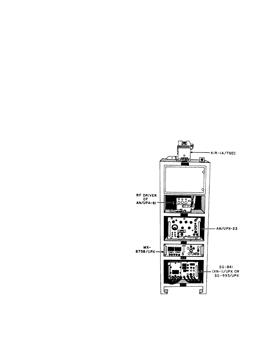
MODE 4.— Mode 4 operation is for military use
only and allows for secure identification of friendly
aircraft and surface vessels.
IFF automatically
generates a reply code according to a preset crypto key
list. As shown in figure 3-2, mode 4 interrogations use
encoded, multipulse trains with 4 (sync) pulses and an
ISLS pulse, followed by up to 32 information pulses.
When the transponder receives and processes a
valid mode 4 interrogation, it sends out a time-coded,
three-pulse reply. The interrogator converts the valid
mode 4 reply back to one pulse. The reply is then time
decoded before it is presented on the indicator. There
are no emergency replies for mode 4 or mode C.
MODE C.— Mode C replies used by civilian and
military aircraft indicate aircraft altitude and are taken
automatically from the aircraft’s barometric altimeter.
Mode C interrogations are the same as those for SIF
modes. Replies are binary codes contained between
bracket pulses similar to those for SIF modes.
The reply, derived from an encoder linked to the
aircraft altimeter, may represent any altitude from
-1,000 feet to +126,700 feet in 100-foot increments.
Shipboard transponders are wired to reply to mode C
interrogations with bracket pulses only (code 0000).
Commercial aviation has implemented the Traffic
Alert and Collision Avoidance System (TCAS), which
uses a low-power mode C interrogator-processor.
Using mode C altitude reports, it computes the closest
point of approach (CPA) to other aircraft and displays
the information as an overlay on the weather radar
indicator. General aviation aircraft flying below 12,500
feet reply to mode C with empty brackets (code 0000),
the same code used by Navy ships.
TCAS cannot distinguish between replies sent by
your ship and those sent by small aircraft. It assumes
that a mode C target is at the same altitude as itself if no
altitude is reported. Therefore, your ship’s mode C reply
can set off a projected collision alarm in the cockpit of
an arriving or departing airliner, causing the pilot to
make unnecessary and dangerous maneuvers. Since
this situation is a great threat to air safety, your
transponder’s mode C should always be secured in or
near port, unless you are testing the unit, with the
antenna disconnected.
internally.
Equipment Components
As we mentioned earlier, the interrogator and
transponder sections of the AIMS Mark XII IFF operate
independently of each other.
In the following
paragraphs, we’ll discuss each section, beginning with
the interrogator section.
INTERROGATOR SECTION.— The major units
of the interrogator section (except the video decoder
group) are usually mounted in a rack located in the radar
equipment room, as shown in figure 3-3.
A simplified block diagram of the interrogator
section is shown in figure 3-4. The Interrogator Set
AN/UPX-23, provides rf challenges for the various
modes.
It also receives transponder replies and
processes them into proper video signals for application
to the decoders and indicators.
The pulse generator provides IFF system
pretriggers that initiate challenges for the enabled
modes. In a “slaved IFF system,” associated with a
specific radar, the pulse generator synchronizes the
interrogations with the radar. In a “black IFF system,”
not associated with a radar, it produces triggers
Figure 3-3.—Mark XII IFF interrogator equipment.
3-4
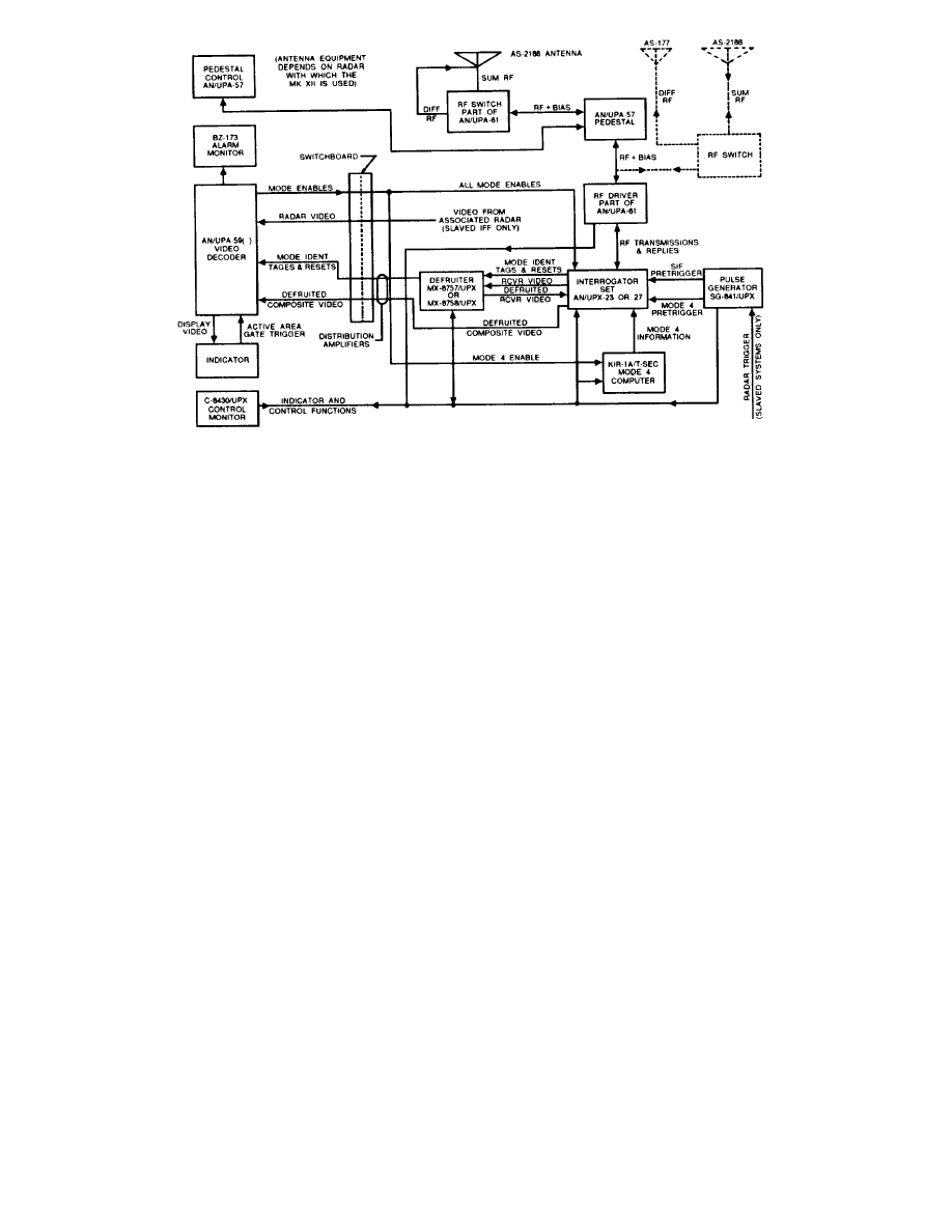
Figure 3-4.—Mark XII IFF system interrogator station.
The Computer, KIR-1A/TSEC, encodes mode 4
challenges for transmission by the interrogator. It also
decodes the received mode 4 transponder replies. The
code changer key, TSEC/KIK-18, inserts the mode 4
code into the computer.
The Video Decoder, AN/UPA-59(), has various
configurations. The most common configuration uses a
video decoder, an intra-target data indicator, and an
alarm monitor.
The video decoder provides control signals that the
interrogator uses to display challenges in the various
modes. It also decodes and processes reply video (mode
4 video goes directly through without processing) and
provides video output to the indicator. The video
decoder will accept radar video from an associated radar
and route it, with or without IFF video, to the indicator
for display. An intratarget data indicator plugs into a
receptacle in the decoder’s front panel. It provides
readouts of reply codes for modes 1, 2, and 3/A and
direct altitude readouts for mode C. The alarm monitor
contains a loud speaker and indicator lights to provide
audible and visual alarms when IFF emergency signals
are decoded.
The defruiter can be one of two types of
interference blankers. The MX-8757/UPX is a
four-channel type, using one channel per mode for
modes 1, 2, 3/A, and C. The MX-8758/UPX is a
one-channel type, using one channel for all modes.
Both units remove nonsynchronous transponder replies
(fruit) and receiver noise from IFF video.
The control monitor functions as a remote
control and remote monitor for the interrogator
section. The front panel of the control monitor is
shown in figure 3-5.
The Switch and Driver, AN/UPA-61, provides
ISLS operation for the Mark XII system. Targets at
close range may reply to side and back lobes, as well as
to the main antenna beam. This could cause a target to
appear for nearly 360 degrees close to the origin of the
display, a phenomenon known as “ring-around.” ISLS
prevents ring-around by inhibiting transponder replies
to side lobes.
The Antenna Pedestal Group, AN/UPA-57, can
operate in any of three modes: slaved to a radar system,
self-synchronous, or manually. It consists of a manual
pedestal control unit, a control power supply unit, an
antenna pedestal assembly, and a pedestal disconnect
mast switch.
The manual pedestal control is usually located at
the ppi. The front panel controls allow the selection of
free run, slave, or manual operation. The control power
supply unit, located below decks, develops all power
required for the antenna pedestal group. In the free run
operation mode, the power supply unit can rotate the
pedestal assembly at up to 15 rpm. When slaved to a
3-5
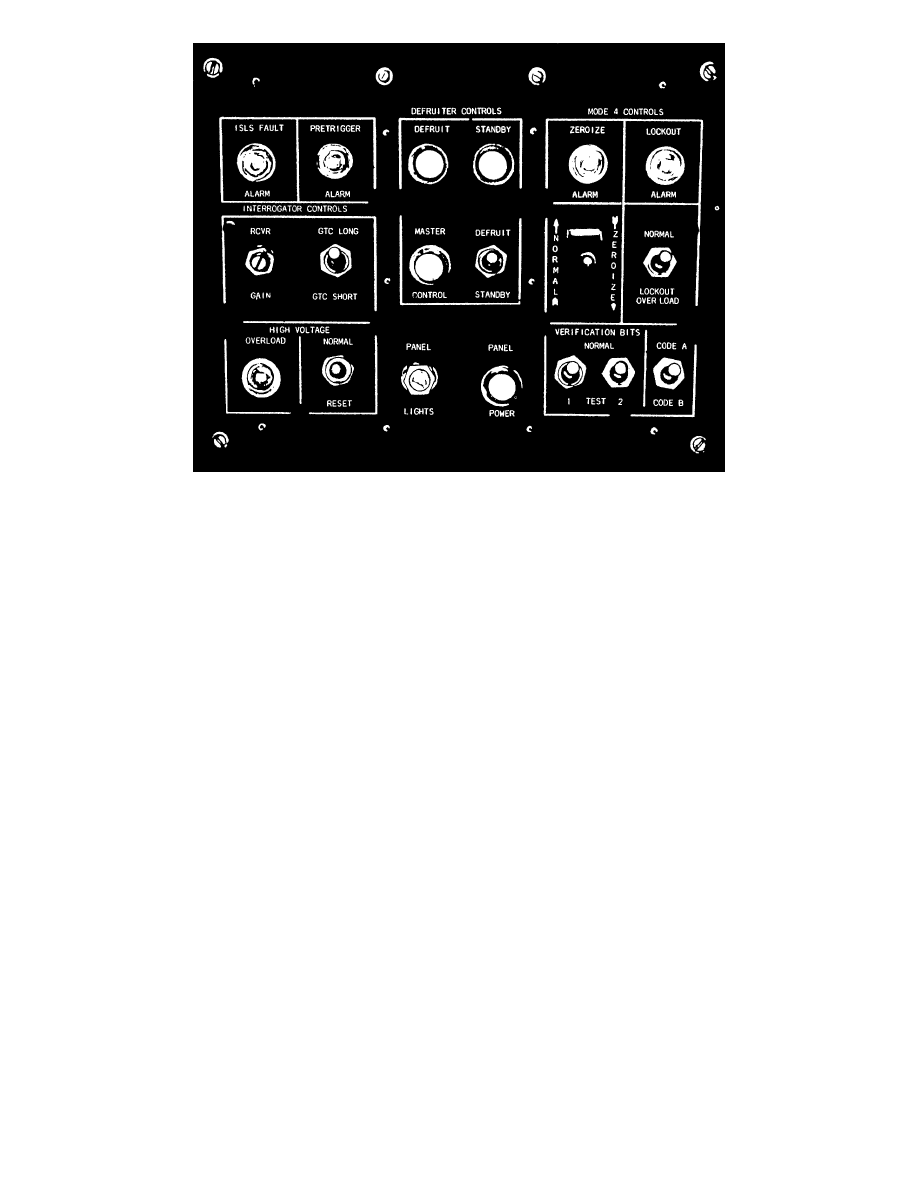
Figure 3-5.—Control monitor front panel.
radar, it can accommodate rotation rates from 2 to 30
rpm, receiving radar synchro information via the
radar switchboard. In the manual mode, it can
position the antenna to any azimuth directed from a
remote position. The antenna pedestal assembly can
mount the AS-2188( )/UPX or any other 10-foot
antenna designed to mount on the same platform. The
pedestal disconnect mast switch, located above decks,
removes all power from the pedestal assembly.
The selection of system antenna equipment
depends on which radar is using the Mark XII system.
For installations where the rotary joint will not pass
the switching bias, the AS-2188( )/UPX will transmit a
sum pattern only, with a separate AS-177( )/UPX
omnidirectional antenna transmitting the difference
rf. Some installations use an integral antenna to
transmit and receive both radar and IFF signals, with
difference rf transmitted on a separate AS-177( )/UPX
antenna.
TRANSPONDER SECTION.—The transponder
receives interrogation pulses and, in turn, generates
the proper reply pulses. A simplified block diagram of
a typical shipboard transponder section is shown in
figure 3-6. As we discussed before, desired reply codes
are set by thumbwheel switches for modes 1, 2, and
3/A; ships are wired for code 0000 mode C replies.
Mode 4 replies are coded automatically according to
the crypto key installed in the TSEC/KIT-1A.
The organizational-level maintenance of the
Mark XII IFF system is performed by ETs (NEC ET-
1572). You must have formal training or written
permission from your commanding officer to work on
the TSEC/KIR-1, TSEC/KIT-1, or TSEC/KIK-18
crypto units.
The AIMS Newsletter, published by Naval
Electronic Systems Engineering Activity (NESEA) St.
Inigoes, Maryland, provides information to shipboard
technicians and operators on AIMS systems, primarily
Mk XII IFF and its related subsystems. It keeps you
up to date on any equipment modifications, PMS
changes, and significant interface problems. It also
gives you an AIMS hotline number to use if you have
any questions or problems concerning maintenance or
operation of Mk XII IFF equipment. You can find
more information on this publication in ET, Volume 2,
Administration.
Agreements between the Navy, Air Force, and
FAA, under the AIMS program, required the
development of a system to present ATCRBS data
instantly, in symbolic and numeric form, directly on
the indicator, and superimposed over live radar video.
The AIMS Mark XII IFF system does this for ships.
Under the AIMS
3-6
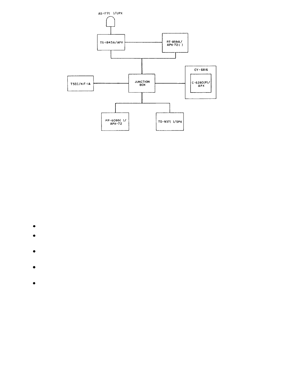
Figure 3-6.—Typical shipboard Mark XII transponder section.
program, the Navy, Air Force, and FAA further agreed
on specifications for a ground/shore-based
configuration called the DAIR system.
DIRECT ALTITUDE AND IDENTITY
READOUT (DAIR) SYSTEM
The DAIR air traffic control system provides
several different types of configurations for different
user requirements. They are as follows:
Type 5, DAIR
Type 10, Radar Air Traffic Control Facility
(RATCF) DAIR
Type 8, Carrier Air Traffic Control Center
(CATCC) DAIR
Type 12, Amphibious Air Traffic Control
(AATC) DAIR
Type 13, Shipboard DAIR.
The Navy Training Plan (NTP) for the Type 13
system is currently being reviewed for approval. This
shipboard DAIR system is scheduled to replace all Type
8 and Type 12 systems in the fleet; however, there is
currently no confirmed time for the conversions. We
will include the specifics of this system in the first
revision of this volume after the NTP is approved and
an installation schedule is set. In the meantime, if you
would like to find out more about the Type 13 system,
contact the instructors who teach the DAIR systems at
the Naval Air Technical Training Center, NAS
Memphis, Millington, TN.
All the types of DAIR systems use an operator (or
a team of operators) to control air traffic via display
devices.
Each operator gathers and assembles
information by monitoring and operating display
devices. The operators use this information to control
air traffic within a given area.
DAIR (AN/TPX-42A(V)5)
AN/TPX-42A(V)5 gives the air traffic controller
rapid, positive identification and altitude data on
transponder-equipped aircraft. It is used for
ground-controlled approach at shore installations, such
as Naval and Marine Corps air stations (NAS, MCAS),
radar operational facilities (ROF), and radar air traftlc
control facilities (RATCF). At expeditory airfields, the
AN/TPX-42(V)5, in a transportable shelter with ASR,
is used by Marine Air Traffic Control Squadrons
(MATCS). This system operates with a primary radar.
The radar supplies synchronizing triggers and azimuth
data to the system.
The DAIR information is
superimposed on the primary radar video.
3-7

All the equipment for the DAIR system, except
antennas, is installed in remote shelters, vans, control
rooms, and equipment buildings. Depending on the
requirements of the site, a variety of configurations
could be used.
RATCF DAIR (AN/TPX-42A(V)10)
RATCF DAIR is used at major shore installations
to increase the capability of the AN/TPX-42A(V)5
interrogator system. This programmable system retains
all the features of the DAIR system and modifies the
signal-processing chain.
The use of computer-
processed data increases controller efficiency and traffic
handling capability. Some of the RATCF DAIR new
capabilities include:
Automatic tracking of emergency targets
Audible and visual alarm when an aircraft
descends below a preselected minimum altitude
Altitude monitoring with an alarm when targets
stray 300 feet from controller-assigned altitude
Semi-automatic handoff and exchange of flight
data between operators and facilities
RATCF DAIR offers an expanded display and
aircraft tracking capability and impacts other radar
systems in the same way as DAIR The RATCF DAIR
interfaces with FAA enroute centers, ARTS facilities, Air
Force PIDP facilities, and other RATCF DAIR facilities.
CATCC DAIR (AN/TPX-42A(V)8)
The AN/TPX-42A(V)8 is designed for air traffic
control aboard aircraft carriers. Its radius of coverage
can extend to 200 nautical miles, although air traffic
controllers are responsible only out to 50 nautical miles.
Controllers cover their area of responsibility using the
alphanumeric display of flight identity, altitude, and
other pertinent information provided by this system and
superimposed over primary radar video.
The CATCC DAIR system accepts trigger and
azimuth data from several shipboard radars. It also
accepts ship’s data such as speed, heading, position,
clock time, and barometric pressure and displays them
in a tabular list on the controller’s indicator. The system
automatically computes the final bearing and displays it
as a vector on the indicators.
A controller can put flight information into the
system, via a keyboard, up to 24 hours before aircraft
take-off or recovery. The system automatically tracks
aircraft (using beacon response), matching each aircraft
with the proper identification data from the flight data
tabular list. As each aircraft leaves the controller’s area
of responsibility, its track is passed to another CATCC
control position, CIC, or ACLS/PALS as appropriate.
Some of the significant operating capabilities of the
CATCC DAIR system include:
Automatic tracking and alphanumeric identity of
selected aircraft by aircraft side numbers
Independent radar selection by position
The ability to accept NTDS map or to draw anew
or modified map from a keyboard
Independent maintenance modes for displays
with computer-driven maintenance patterns
Built-in Test Equipment (BITE) with computer-
assisted diagnostics
Figure 3-7 shows a typical CATCC DAIR system
interface diagram. CATCC DAIR interfaces with many
systems including:
NTDS
Keyset Central Multiplexer (KCMX)
ACLS/PALS
IFF
RD-379 recorders
Radar switchboards
CATCC DAIR equipment is installed in the
CY-7567 electrical cabinet and the MT-4939 and
MT-4940 electrical equipment racks located in the
auxiliary radar room. The CATCC operations room has
5 indicator-control groups and 5 keyboard controllers,
including the emergency IFF/radar switch.
AATC DAIR (AN/TPX-42A(V)12)
The AATC DAIR system is designed for air traffic
control aboard LHA, LPH, and LHD amphibious ships.
Display capabilities are similar to those of CATCC
DAIR, but new equipment and software programs
provide capabilities needed for amphibious operations.
The controller is provided the identity, altitude, and
status of IFF-equipped aircraft within the amphibious
objective area (AOA). Information such as Air Plan
Lists and ship’s data are also available for display on the
controller’s console. AATC DAIR uses the IFF beacon
as a primary means of target detection and tracking, but
3-8
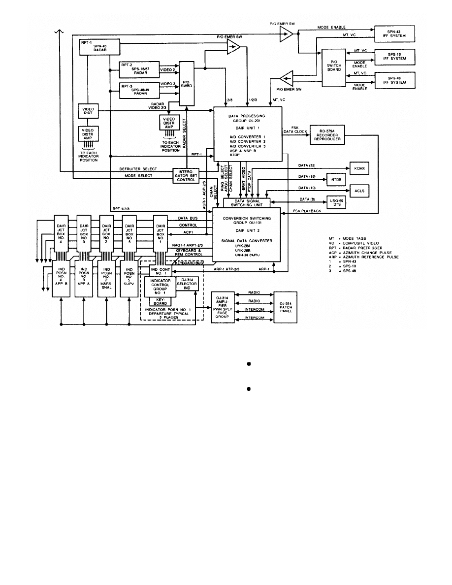
Figure 3-7.—CATCC DAIR system interlace block diagram.
also incorporates primary radar track processing as a
backup.
The AN/TPX-42A(V) 12 does not replace any
existing system. On amphibious-type ships, 4 indicator
control groups (consoles) are located in the Helicopter
Direction Center (HDC). Additional consoles are
located in the Tactical Air Control Center (TACC) on
LHA- and LHD-type ships. To accommodate the
installation, some existing consoles may be removed
from these locations, but no system is replaced. Field
change kits will update currently installed CATCC
DAIR systems on CV- and CVN-type ships to the (V)12
configuration.
The AATC DAIR interfaces with the same systems
as CATCC DAIR, with the following additional
interface capabilities:
Integrated Tactical
System (ITAWDS)
Amphibious Warfare Data
Shipboard Data Multiplex System (SDMS)
MAINTENANCE
The organizational maintenance for the DAIR
systems is done by ETs (NEC ET-1574 for DAIR,
ET-1576 for CATCC DAIR, ET-1576 with 2 weeks of
difference training for AATC DAIR, and ET-1578 for
RATCF DAIR). You will perform both on-line and
off-line tests and alignment, system operational checks
and adjustments for CATCC and AATC DAIR, and
periodic inspection, verification and cleaning of certain
equipments in RATCF DAIR. By using BITE for
on-line fault isolation, you will be able to isolate faults
3-9
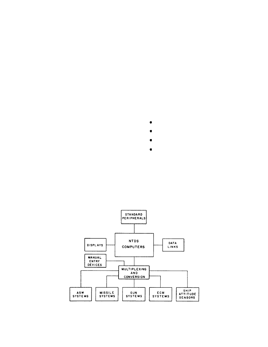
to discrete components and, in some cases, to a set of
several digital cards. You’ll complete most repairs by
removing and replacing discrete chassis components,
modules, or digital circuit cards.
The Air Force performs depot-level maintenance on
DAIR equipment under a joint maintenance task
agreement; however, the contractor will repair all
CATCC- and AATC DAIR-unique items at the depot
level. Return the items that you can’t repair to supply.
They’ll know where to send them.
All the systems we’ve discussed so far are the
maintenance responsibility of the ET rating. The next
system, NTDS, is maintained by several ratings. As we
explained in ET, Volume 3, Communications Systems,
the only way to ensure optimum operation of the NTDS
system is to work closely with the other ratings involved.
NAVAL TACTICAL DATA SYSTEM
(NTDS)
ET, Volume 3, addresses the NTDS tactical
communications data system. In this volume, we will
address the tactical radar section.
The NTDS
computer-centered control system coordinates the
collection of data from various sources. It accepts data
from ship’s sensors, such as radar, sonar, and navigation
inputs, and from external (off-ship) sources via
communications links. It also processes and correlates
this data for tactical use.
GENERAL THEORY OF OPERATION
NTDS accomplishes its objectives in real time; the
system receives data from various sensing devices that
are in continuous contact with the outside environment.
It uses this data to evaluate an event as it happens. How
often the system requires an update will determine the
rate of sampling for each sensing device. The concept
of standard computers operating in conjunction with
each other to increase capacity and functional capability
is known as the “unit computer concept.” It is basic to
the design philosophy of NTDS. A diagram of a typical
NTDS equipment grouping is shown in figure 3-8.
NTDS integrates all systems and subsystems for
performing the basic combat system functions
including:
Detection and entry
Tracking and identification
Threat evaluation and weapon assignment
Engagement and engagement assessment
The NTDS system accomplishes its varied tasks by
receiving, storing, and processing the data inputs from
the other systems and subsystems. The operational
program then distributes the processed data as usable
inputs for other systems and subsystems. The data
display also allows the operator to interact with the
system.
Figure 3-8.—NTDS equipment grouping.
3-10

MAINTENANCE
VOLUME 2—OPERATIONAL SEQUENCES
As an ET, you are responsible for maintaining the
radar, antenna, video and sync amps, and radar
switchboard, plus any associated equipment directly
connected to this group.
All ships with NTDS have a Combat Systems
Technical Operations Manual (CSTOM). The CSTOM
documents the total integrated combat systems concept;
you will find it a
useful guide regarding
communications, radar, and NTDS as a whole integrated
system.
The CSTOM organizes the technical data associated
with the integrated combat system, providing
information required to both operate and maintain the
system.
It defines significant capabilities and
limitations of the system, and even outlines
requirements for maintaining material and personnel
readiness for the system. The publication is structured
as follows:
VOLUME 1—COMBAT SYSTEMS DESCRIP-
TION
VOLUME 3—COMBAT SYSTEM READINESS
VOLUME 4—CAPABILITIES AND LIMITA-
TIONS
As you may imagine, with such an all-
encompassing system, troubleshooting may take you
beyond ET lines of maintenance responsibility. If the
system has a problem, you should be aware of what the
FCs, or DSs, or ICs are doing. Your expertise on the
radar or the radar distribution switchboard may help
prevent them from wasting their time. Being aware of
what other ratings are doing also will allow you to
become more familiar with other equipment and more
knowledgeable about what could affect your equipment.
Regardless of your technical knowledge on a piece
of gear, you must know the safety requirements
associated with that gear before you work on it. In the
next chapter, we will discuss safety aspects that are
specific to radar maintenance.
3-11


CHAPTER 4
RADAR
You are now a radar systems technical expert. As
an Electronics Technician, Second Class, and possible
work center supervisor, you also must understand the
basic safety requirements for radar maintenance and
operation.
In ET Volume 1, Safefy, we discussed the following
safety items that apply to radar: (1) the proper handling
of cathode-ray tubes (CRTs), (2) measuring voltage on
energized equipment, (3) the use of protective
equipment, (4) tag-out procedures, (5) working aloft,
and (6) RF hazards.
We will not cover that material in this volume.
However, we will test your understanding of that
material in the NRTC for this volume. Therefore, if you
have not completed Volume 1, you may want to do so
before proceeding with this course.
RADIATION HAZARDS
Much of your radar gear (if labeled correctly) will
have radiation hazard (RADHAZ) warnings attached.
These labels indicate a radiation hazard producing RF
electromagnetic fields intense enough to actuate
electro-explosive devices, cause spark ignition of
volatile combustibles, or produce harmful biological
effects in humans. You will probably not be able to
eliminate the hazards caused by normal operation of
your radar equipment. Therefore, you will need to
minimize them during certain evolutions.
The most effective way to reduce radiation hazards
is to shut down equipment when possible or to locate
equipment so that radar main beams do not illuminate
ordnance, personnel, or fuels.
NAVSEA OP 3565 requires each commanding
officer to establish procedures for maintaining positive
control of RF transmitting equipment and to coordinate
the actions of personnel working near emitters or
handling ordnance. By instruction, no one may turn on
a n y transmitting equipment without proper
authorization from the supervisor in charge of
operations. That means that you need permission to
operate, test operate, rotate, or radiate electronic gear.
Each command has an Emissions Control
(EMCON) Bill that establishes the level of EMCON
SAFETY
required during certain types of operations. The
EMCON bill identifies the equipment to be secured
while each EMCON level is set. Label your radar
equipment according to your EMCON bill to make
identification easy and to provide for timely shut down.
The following paragraphs discuss the primary
adverse affects of electromagnetic radiation on material
and personnel and the programs designed to minimize
those effects.
HERO—HAZARDS OF
ELECTROMAGNETIC
RADIATION TO ORDNANCE
During on-loading or off-loading of ammunition,
there is a danger that RF electromagnetic fields could
accidentally activate electro-explosive devices (EEDs)
or electrically-initiated ordnance. This is a very real
hazard to the ordnance, the ship, and the crew. The
HERO program was developed to control these types of
situations.
When HERO is set, it usually requires that radars be
secured. When you are in port and must conduct any
radar maintenance requiring rotating the antenna or
radiating, always coordinate your actions with Base
Operations via the CDO. HERO conditions anywhere
in the area could be affected by your radar. Even if you
just want to radiate a short period for an operational test,
check with the OOD or CDO first.
Table 4-1 identifies ordnance hazards associated
with common electronic equipment. This is an example
of tables found in NAVSEA OP 3565 Volume II, part 1.
HERF—HAZARDS OF
ELECTROMAGNETIC
RADIATION TO FUELS
The HERF program was developed to protect
fueling operations.
During fueling operations, RF
electromagnetic fields with a large enough intensity
could produce a spark that could ignite the volatile
combustibles. Therefore, certain radars may need to be
shut down during fueling operations. Check your
HERF publications for specific details.
4-1
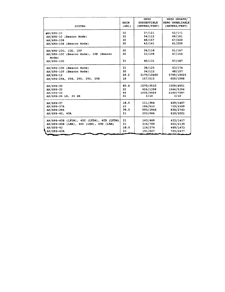
Table 4-1.—NAVSEA OP 3565 Volume II, Table 2-4, Safe Separation Distances for Radar, EW, and NAVAIDS Equipment
HERP—HAZARDS OF
ELECTROMAGNETIC
RADIATION TO PERSONNEL
The HERP program was developed to protect
personnel from RF electromagnetic radiation.
Anywhere a radar or transmitter is operating, there is a
danger that the RF electromagnetic fields may produce
harmful biological effects in humans exposed to them.
The following paragraphs identify the typical hazards
and the steps you can take to minimize them.
example of tables found in NAVSEA OP 3565 Volume
I.
RF BURNS.— As we mentioned in ET Volume 1,
voltages of enough potential to cause a burn injury can
be induced on metallic items from nearby transmitting
antennas.
However, there has to be actual physical
contact for the burn to occur. You can help prevent
contact by ensuring that warning signs are placed
properly and obeyed.
Precautions
Hazards
RF hazards to personnel are based on overexposure
to RF energy. The biological hazard level for exposure
to RF radiationis established by the Bureau of Medicine
and Surgery and is included in NAVSEA OP 3565
Volume I.
SAFE LIMITS.— Safe limits are based on the
power density of the radiation beam and the exposure
time of the human body. Table 4-2 identifies safe limits
associated with common electronics equipment. It is an
During normal operations, personnel can easily
avoid most hazards if the hazards are labeled properly.
However, during maintenance, some hazards must be
eliminated by specific, planned actions, such as those
listed below. Using all safety precautions is the personal
responsibility of the technician.
TAG-OUT.— Tag-out procedures are covered in
depth in ET Volume 1. Hanging a proper tag can save
your life. Using tags improperly or not at all will
eventually put you, maybe your best buddy, maybe your
4-2
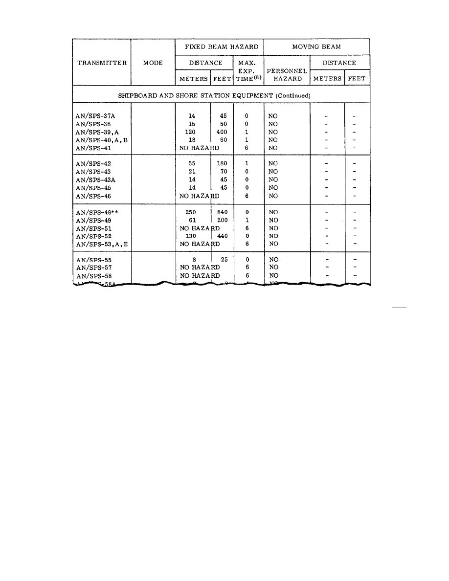
Table 4-2.—NAVSEA OP 3565, Volume I, Table 2-1, Personnel Hazards from Continuous or Intermittent Exposure to Main Beam
Radiation
whole crew, in a Navy mishap report. Ensure that
become familiar with the hazards associated with your
required tags are installed properly and observed fully.
MAN-ALOFT CHITS.— Man-Aloft chits protect
you from RF hazards when you are working on radar
antennas. If the chit is run properly, the operations on
your ship and any ship next to you are modified to keep
you safe.
Heed the requirements and follow the
procedures.
EQUIPMENT SAFETY DEVICES.— Devices
built into equipment, such as cut-off switches on
antennas, are for your safety. A cut-off switch, when set,
will keep you out of danger. It will prevent someone
from rotating the antenna from a remote location. But,
you, the technician, have to set the cut-off switch for it
to be of any use. Equipment safety devices are there for
your protection. Use them!
Everywhere you go in the Navy, there will be
communications and radar equipment that produces an
Electromagnetic Radiation Environment (EME). And,
there will always be electromagnetic radiation hazards
introduced by operating this equipment. To be safe,
equipment. If you install new equipment, update your
EMCON bill. Use NAVSEA OP 3565 Volume I or
Volume II to determine the hazards associated with the
equipment.
OTHER RADAR HAZARDS
You cannot always avoid hazards when working on
radars. In these instances, take what precautions you
can and at least be prepared for an emergency. As we
discussed in ET Volume 1, there are various safety
concerns associated with working on energized
equipment, going aloft, or handling CRTs.
ENERGIZED EQUIPMENT
You may have to work on energized equipment on
a hectic bridge, in a crowded CIC, or in a cramped radar
equipment room. These are not ideal safety
environments.
As these spaces are maintained by
various people, always check the rubber matting around
your equipment.
Also check other protective
4-3
equipment, such as rubber gloves and shorting probes
before using them.
WARNING!
NEVER WORK ALONE ON ENERGIZED
EQUIPMENT.
On ships with minimum manning, you may not have
the option of using another ET as a safety observer.
Make sure that whoever is going to observe you is CPR
qualified. Brief your observer on what you will be
doing. Physically show him or her where the cut-off
switch is located. Have him or her stand by at a safe
distance with a rope or wooden cane to pull you from
the equipment, should you get hung up. Follow
procedures outlined in ET Volume 1 for voltage checks.
MAN-ALOFT
As we mentioned earlier, when you work aloft on
radar antennas, your man-aloft chit protects you from the
RF radiation hazards. But, you also need to be protected
from falling. Do the required PMS for safety harnesses
every time you use the harness. And remember, even a
good harness can’t save you unless you use it right. When
you go up the mast attach your harness properly so you
can’t free fall to the deck. Attach a line to any tools you
carry up, so they are unable to fall freely. Set the cut-off
switches for any antennas along your way.
WARNING!
NEVER WORK ALOFT
SAFETY OBSERVER.
WITHOUT A
It’s your life; pick good safety observers. Your
safety observers should be aware of what type of
maintenance you’re going to do. They also need to
know whom to contact if you run into technical
problems.
Safety Observers are responsible for the safety of those
walking underneath you as well as for your safety. They
should position themselves so you can communicate with
them without having to come down. The safety observer
will pass your information to everyone else. If something
is falling, communicate quickly.
CATHODE-RAY TUBES (CRT’S)
Cathode-ray tubes are part of radar scopes. You will
definitely have to work around them. You will probably,
at one time or another, pack or unpack, install, repair, or
dispose of one.
There are some very real dangers
associated with handling a CRT. Always take the
precautions discussed in ET Volume 1 whenever you
handle a CRT.
Never think about electronics without thinking
about safety. Learn from the safety information you get
from the Ship’s Safety Bulletins, Navy mishap reports,
and personal experience. Follow established
procedures and all safety instructions. Live longer.
We’ve discussed many aspects of radar in this
volume.
In ET Volume 7, Antennas and Wave
Propagation, we will provide specific information
about radar antennas, waveguides, and transmission
lines. Then in ET Volume 8, System Concepts, we will
discuss specifics on radar cooling systems.
4-4

APPENDIX I
GLOSSARY
2-M— Microminiature electronic repair.
2D RADAR— Two dimensional; the radar provides
information on two separate coordinates (usually
range and azimuth).
3D RADAR— Three dimensional; the radar provides
information on three separate coordinates (usually
range, azimuth, and altitude).
A/D— Analog/digital.
AATC DAIR— Amphibious air traffic control DAIR uses
an AN/TPX-42A(V)12 and is known as a type 12 system.
AAW— Antiair Warfare.
ACLS— Autostatic Carrier Landing System.
ADT— Automatic detection and tracking.
AFC— Automatic frequency control.
AIC— Air intercept control.
AMW— Amphibious warfare.
AOA— Amphibious objective area.
APG— Azimuth pulse generator.
APL— Allowance parts list.
ASAC— Antisubmarine aircraft control.
ASM— Antiship missile.
ASUW— Antisurface warfare.
ASW— Antisubmarine warfare.
ATC— Air traffic control.
ATCRBS— Air Traffic Control Radar Beacon System.
ATD— Automatic target detection.
BIT— Built-in-test.
BITE— Buih-in-test equipment.
CAC— Command and control.
CAP— Combat Air Patrol.
CATCC— Carrier Air Traffic Control Center.
CATCC DAIR— Carrier Air Traffic Control Center
DAIR system uses a AN/TPX-42A(V)8 and is
known as a type 8 system.
CCA— Carrier controlled approach.
CCS— Central computer subsystem.
CDO— Command duty officer.
CFAR— Constant false alarm rate.
CIC— Combat information center.
CM— Corrective maintenance.
CPA— Closest point of approach to other surface craft
or aircraft.
CPR— Cardiopulmonary resuscitation.
CRT— Cathode ray tube.
CSLC— Coherent sidelobe canceler.
CSTOM— Combat Systems Technical Operations
Manual.
CW— Continuous wave.
DAIR— Direct Altitude and Identity Readout. The
standard DAIR system uses an AN/TPX-42A(V)5
and is known as a type 5 system.
DCSC— Digital coherent sidelobe canceler.
DFS— Direct fleet support.
DMTI— Digital moving target indicator.
DOP— Designated overhaul point.
DRA— Dead reckoning analyzer.
DUCTING— The increased bending of radar waves as
they pass through abnormal atmospheric
conditions.
ECM— Electronic countermeasures.
EED— Electro-explosive devices.
EIMB— Electronics Installation and Maintenance
Book.
EMCON— Emissions control.
EME— Electromagnetic radiation environment.
EMI— Electromagnetic interference.
ET— Electronics Technician.
FC— Fire Control Technician.
AI-1

FM— Frequency modulation.
FRUIT— Nonsynchronous transponder replies that
interfere with IFF video.
FTC— Fast time constant.
GCA— Ground controlled approach.
GPETE— General-pufpose electronic test equipment.
HDC— Helicopter direction center.
HERF— Hazards of electromagnetic radiation to fuel.
HERO— Hazards of electromagnetic radiation to
ordnance.
HERP— Hazards of electromagnetic radiation to
personnel.
I/O— Input/output.
IADT— Integrated Automatic Detection and Tracking
System.
IF— Intermediate frequency.
IFF— Identification friend or foe.
IMA— Intermediate maintenance activity.
IS— Interference suppression.
LSLS— Intemogator side lobe suppression.
ITAWDS— Integrated Tactical Amphibious Warfare
Data System.
KCMX— Keyset central multiplexer.
LED— Light-emitting diodes.
LOS— Line of sight.
LRM— Long range mode.
LRU— Lowest replaceable unit.
LSO— Landing signal officer.
MAM— Maintenance assist module.
MATCS— Marine air traffic control squadrons.
MCAS— Marine Corps air station.
MFC— Manual frequency control.
MLV— Memory loader/verifier.
MOB— Mobility.
MOISTURE LAPSE— A falling away from the
standard moisture content of the air.
MOTU— Mobile technical unit.
MPPI— Maintenance planned position indicator.
MPU— Medium PRF upgrade.
MRC— Maintenance requirement card.
MTBF— Mean time between failures.
MTI— Moving target indicator.
MTTR— Mean time to repair.
MTU— Magnetic tape unit.
MUTE— Shipboard Emission Monitor-Control Set,
AN/SSQ-82(V).
NAS— Naval air station.
NAVSEA— Naval Systems Engineering Activity.
NAVSEACEN— Naval Systems Engineering Activity
Center.
NEC— Navy Enlisted Classifications.
NEETS— Navy Electricity and Electronics Training
Series.
NTDS— Navy Tactical Data System.
OCC— Operator control console.
OOD— Officer of the deck.
PA— Power amplifier.
PALS— Precision Approach Landing System.
PAR— Precision approach radar.
PCB— Printed circuit board.
PM— Planned/preventive maintenance.
PMS— Planned Maintenance System.
PPI— Planned position indicator.
PRF— Pulse repetition frequency, also referred to as
pulse repetition rate (PRR).
PRI-FLI— Primary flight.
PRR— Pulse repetition rate, also referred to as pulse
repetition frequency (PRF).
R/T— Receiver/transmitter.
RADDS— Radar Display and Distribution Systems.
RADHAZ— Radiation hazard.
RATCF DAIR— Radar Air Traffic Control Facility
DAIR system uses the AN/TPX-42A(V)10 and is
known as a type 10 system.
RF— Radio Frequency.
RFI— Radio frequency interference.
AI-2

RFSTC— RF sensitivity time control.
RHI— Range-height indicator.
RING-AROUND— The appearance of a target close to
the origin of the display screen that extends nearly
360 degrees. Usually a result of close-in targets
responding to side lobe IFF interrogations.
ROF— Radar operational facilities.
RPM— Rotation per minute.
RSC— Radar set control.
RTS— Radar test set.
RVC— Radar video converter.
RVP— Radar video processor.
SBBM— System/bootstrap bus monitor.
SDC— Signal data converter.
SDMS— Shipboard data multiplex system.
SEM— Standard electronic modules.
SHM— Ships heading marker.
SIF MODES— Selective identification feature modes
of IFF (modes 1, 2, and 3/A) used by friendly
aircraft and surface craft.
SM & R C ODE — S o u r c e ,
recoverability code.
SMS— Ships motion sensor.
maintenance, and
SPETE—
Special-purpose electronic test
equipment.
SPW— Special warfare.
SR— Sector radiate.
SRF— Ship repair facility.
SRM— Short range mode.
SSTX— Solid-state transmitter.
STALO— Stable local oscillator.
STC— Sensitivity time control.
STEEP— Support and Test Equipment Engineering
Program.
SVC— Sensitivity velocity control.
TACC— Tactical Air Control Center on LHA and LHD
type ships.
TAO— Tactical action officer.
TCAS— Traffic Alert and Collision Avoidance
System.
TEMPERATURE INVERSION— An atmospheric
condition in which the normal properties of the
layers of the air are reversed.
TRS— Technical repair standards.
VCS— Video clutter suppression.
VSWR— Vohage standing wave ratio.
AI-3


APPENDIX II
REFERENCES USED TO DEVELOP
THE TRAMAN
NOTE: Although the following references were current when this TRAMAN
was published, their continued currency cannot be assured. You, therefore, need to
ensure that you are studying the latest revision.
AIMS Newsletter Number 24, Naval Electronic Systems Engineering Activity, St.
Inigoes, Md, February 1993.
Navy Electricity and Electronics Training Series, Module 18, Radar Principles,
NAVEDTRA 172-18-00-84, Naval Education and Training Program
Management Support Activity, Pensacola, Fl., 1984.
Navy Training Plan, AN/SPA-25G Indicator Group and SB-4229/SP
Switchboard, NTP S-30-8304B, Chief of Naval Operations, Washington,
DC, April 1988.
Navy Training Plan, AN/GPN-27 Airport Surveillance Radar, NTP E-50-7902A,
Chief of Naval Operations, Washington, DC, May 1986.
Navy Training Plan, AN/SPS-40B/C/D/E Radar, NTP S-30-7127H, Chief of Naval
Operations, Washington, DC, January 1991.
Navy Training Plan, AN/TPX-42(V)5, 8, 10, NTP E-50-7005E, Chief of Naval
Operations, Washington, DC, May 1986.
Navy Training Plan, AN/TPX-42(V)12 AATC DAIR, NTP E-50-8502, Chief of
Naval Operations, Washington, DC, August 1990.
Navy Training Plan, AN/SPN-46(V) Precision Approach Landing System
(PALS), NTP E-50-8206C, Chief of Naval Operations, Washington, DC,
April 1989.
Navy Training Plan, AN/TPS-49( V) Series Radar, NTP S-30-7515H, Chief of Naval
Operations, Washington, DC, January 1993.
Navy Training Plan, AN/SPS-55 Surface Search Radar, NTP S-30-7512E, Chief of
Naval Operations, Washington, DC, June 1989.
Navy Training Plan, AN/FPN-63 Precision Approach Radar (PAR), NTP
E-50-7404D, Chief of Naval Operations, Washington, DC, August
1986.
Navy Training Plan, AN/SPS-64(V) 9 Radar, NTP S-30-8106C, Chief of Naval
Operations, Washington, DC, May 1989.
Navy Training Plan, AN/SPS-67(V) Radar, NTP S-30-7716F, Chief of Naval
Operations, Washington, DC, August 1990.
Technical Manual, Electromagnetic Radiation Hazards, Volume I and Volume II,
Part 1, NAVSEA OP 3565, Naval Sea Systems Command, Washington DC, July
1989.
AII-1


INDEX
A
Configuration—Continued
AN/SPS-40E, 2-11
Aims mark XII IFF system modes of operation, 3-2
AN/SPS-49(V), 2-9
emergency replies, 3-3
mode 1, 3-3
mode 2, 3-3
mode 3/A, 3-3
mode 4, 3-4
mode c, 3-4
SIF modes, 3-2
Air search (2D) radars, 2-8
AN/GPN-27(ASR-8), 2-13
AN/SPS-40B/C/D/E, 2-9
AN/SPS-49(V), 2-8
Altitude, 1-26
B
Bearing, 1-3
bearing resolution, 1-4
relative bearing, 1-3
true bearing, 1-3
C
Carrier-controlled approach (CCA) radars, 2-15
AN/SPN-35, 2-16
AN/SPN-43, 2-16
AN/SPN-44, 2-16
AN/SPN-46(V) PALS, 2-15
Configuration, 2-3
ANEPN-63 PAR, 2-18
AN/GPN-27, 2-14
ANISPA-25G, 2-20
AN/SPN-46(V)1, 2-15
AN/SPN-46(V)2, 2-16
AN/SPS-40B/C/D, 2-11
AN/SPS-55, 2-6
AN/SPS-64(V)9, 2-5
AN/SPS-67(V)3, 2-3
D
Direct altitude and identity readout (DAIR) system, 3-7
AATC DAIR (AN/TPX-42A(V)12), 3-8
CATCC DAIR (AN/TPX-42A(V)8), 3-8
DAIR (AN/TPX-42A(V)5), 3-7
RATCF DAIR (AN/TPX-42A(V) 10), 3-8
Type 13, shipboard DAIR, 3-7
G
General theory of operation, 2-2
AN/FPN-63(V), 2-18
AN/GPN-27, 2-14
AN/SPA-25G, 2-19
AN/SPN-46(V), 2-15
AN/SPS-40, 2-11
AN/SPS-49(V), 2-8
AN/SPS-55, 2-6
AN/SPS-64(V)9, 2-5
AN/SPS-67(V), 2-2
radar indicators (repeaters), 2-19
range-height indicator (RHI), 2-23
SB-4229/SP switchboard, 2-22
signal data converter CV-3989/SP, 2-21
General theory of IFF operation, 3-1
challenge, 3-1
interrogator, 3-1
recognition, 3-1
reply, 3-1
transponder, 3-1
INDEX-1

Ground-controlled approach (GCA) radars, 2-15
AN/FPN-63 PAR, 2-18
I
Interfaces, 2-3
AN/GPN-27, 2-14
AN/SPA-25G, 2-20
AN/SPN-46(V), 2-16
AN/SPS-40B/C/D/E, 2-11
AN/SPS-49(V), 2-9
AN/SPS-55, 2-7
AN/SPS-67(V)1, 2-3
AN/SPS-67(V)3, 2-3
SB-4229/SP switchboard, 2-22
Interrogator section, 3-4
antenna pedestal group, AN/UPA-57,
3-5
code changer key, TSEC/KIK-18, 3-5
computer, KIR-1A/TSEC, 3-5
control monitor, 3-5
defruiter, 3-5
interrogator set, AN/UPX-23, 3-4
pulse generator, 3-4
switch and driver, AN/UPA-61, 3-5
video decoder, AN/UPA-590, 3-5
M
Maintenance, 2-3
AN/FPN-63, 2-18
AN/GPN-27, 2-14
AN/SPA-25G, 2-22
AN/SPN-46(V), 2-16
AN/SPS-40B/C/D/E, 2-11
AN/SPS-49(V), 2-9
AN/SPS-55, 2-7
AN/SPS-67(V), 2-3
CV-3989/SP, 2-22
Maintenance—Continued
SB-4229/SP, 2-22
AN/SPS-64(V)9, 2-6
N
Naval Tactical Data System (NTDS), 3-10
Combat Systems Technical Operations Manual
(CSTOM), 3-11
R
Radar detecting methods, 1-3
continuous wave, 1-3
frequency modulation, 1-3
pulse modulation, 1-4
Radar indicators (repeaters), 2-19
A scope, 2-19
AN/SPA-25G indicator group, 2-19
planned position indicator (PPI), 2-19
range-height indicator (RHI), 2-23
Radar performance, 1-4
atmospheric conditions, 1-4
bearing resolution, 1-4
ducting, 1-4
radar accuracy, 1-4
range resolution, 1-4
Radar reference coordinate system, 1-1
azimuth, 1-2
elevation angle, 1-2
horizontal plane, 1-1
line of sight, 1-1
true north, 1-1
true bearing, 1-2
vertical plane, 1-1
Radar safety, 4-1
cathode-ray tubes (CRT’S), 4-4
energized equipment, 4-3
man-aloft, 4-4
INDEX-2

Radar safety—Continued
radiation hazards, 4-1
RF burns, 4-2
safe limits, 4-2
Radar safety precautions, 4-2
equipment safety devices, 4-3
man-aloft chits, 4-3
safety observer, 4-4
tag-out, 4-2
Radar system, 1-4
antenna system, 1-5
duplexer, 1-5
indicator, 1-5
modulator, 1-5
receiver, 1-5
transmitter, 1-5
Radiation hazards, 4-1
HERO-hazards of
ordnance, 4-1
electromagnetic radiation to
HERF-hazards of electromagnetic radiation to
fuels, 4-1
HERP-hazards of electromagnetic radiation to
personnel, 4-2
Range, 1-2
maximum range, 1-2
minimum range, 1-2
range accuracy, 1-2
range resolution, 1-4
S
Surface search and navigation radars, 2-1
AN/SPS-55, 2-6
AN/SPS-64(V)9, 2-3
AN/SPS-67, 2-2
T
Three coordinate (3D) air search radars, 2-14
Transponder section, 3-6
TSEC/KIT-1A, 3-6
Types of radar systems, 1-5
air search, 1-7
height finding, 1-7
navigation, 1-6
surface search, 1-6
INDEX-3


Assignment Questions
Information: The text pages that you are to study are
provided at the beginning of the assignment questions.


ASSIGNMENT 1
Textbook Assignment:
“Introduction to Basic Radar,”
chapter 1, pages 1-1 through 1-8;
and “Radar Systems Equipment Configuration,” chapter 2, pages 2-1
through 2-6.
1-1.
A radar transmits a pulse, and
309 µsec later the radar receives
an echo.
What is the number of
nautical miles between the radar
and the contact?
1. 6.1
2.
12.2
3. 25
4. 50
1-2.
Which method of transmitting radar
energy works well with stationary
or slow- moving targets, but is
not satisfactory for locating
fast-moving objects?
1. AM
2. CW
3. FM
4.
Pulse
1-3.
A radar cannot determine range if
it uses which of the following
types of energy transmission?
1. AM
2. CW
3. FM
4.
Pulse
1-4.
Which of the following methods of
energy transmission is used to a
great extent in Navy radars?
1. AM
2. CW
3. FM
4.
Pulse
1-5.
Which radar unit permits the use
of a single antenna for both
transmit and receive functions?
1.
Antenna
2.
Duplexer
3.
Indicator
4.
Modulator
1-6.
1-7.
1-8.
1-9.
1-10.
Which of the following radar units
supplies rf energy of high power
for short time intervals?
1.
Transmitter
2.
Receiver
3.
Modulator
4.
Duplexer
Which of the following radar units
ensures that intervals between
pulses are of the proper length?
1.
Transmitter
2.
Receiver
3.
Modulator
4.
Antenna
Which of the following radar units
passes the echo to the receiver
with minimum loss?
1.
Transmitter
2.
Duplexer
3.
Modulator
4.
Antenna
Which of the following radar units
converts the weak rf echo to a
discernable video signal?
1.
Duplexer
2.
Modulator
3.
Receiver
4.
Indicator
Which of the following radar units
generates all
pulses?
1.
Duplexer
2.
Modulator
3.
Receiver
4.
Indicator
necessary timing
1

1-11.
1-12.
1-13.
1-14.
1-15.
1-16.
Which of the following radar units
converts the video output of the
receiver to a visual display?
1.
Duplexer
2.
Modulator
3.
Antenna
4.
Indicator
Which of the following radar units
ensures that all subsystems
operate in a definite time
relationship?
1.
Duplexer
2.
Modulator
3.
Antenna
4.
Indicator
Which of the following radar units
converts the echo to an
intermediate frequency?
1.
Duplexer
2.
Antenna
3.
Indicator
4.
Receiver
Which of the following
characteristics influence(s) radar
range performance?
1.
Height of antenna
2.
Peak power of the transmitted
pulse
3.
Receiver sensitivity
4.
All of the above
Which of the following external
characteristics influence(s) radar
performance?
1.
Darkness
2.
Rain
3. PMS
4.
Both 2 and 3 above
Which of the following methods
should you use to do a radar
surface angular measurement?
1.
Measure counterclockwise from
true north
2.
Measure clockwise from true
north
3.
Measure clockwise from the
heading line of the ship
4.
Both 2 and 3 above
1-17.
1-18.
1-19.
1-20.
1-21.
To determine if an echo is a false
target or a true target, what
radar characteristic should you
change?
1. PW
2.
STC
3. PRR
4. RPM
Which of the following radar
reference coordinates is an
imaginary plane parallel to the
earth’s surface?
1.
Horizontal plane
2.
Vertical plane
3. Los
4.
Relative bearing
Which of the following radar
reference coordinates is a line
from the radar set directly to the
object?
1.
2.
3.
4.
Horizontal plane
Vertical plane
LOS
Relative bearing
Which of the following radar
reference coordinates is the angle
measured clockwise from true north
in the horizontal plane?
1.
Relative bearing
2.
Elevation angle
3.
True azimuth angle
4.
Vertical plane
Which of the following radar
reference coordinates is the angle
measured clockwise from the
centerline of a ship or aircraft?
1.
Relative bearing
2.
Elevation angle
3.
Azimuth angle
4.
True bearing
2

1-22.
Which of the following radar
reference coordinates is the plane
in which all angles in the up
direction are measured?
1.
Horizontal plane
2.
Vertical plane
3. Los
4.
Elevation angle
1-23.
Which of the following radar
reference coordinates is the angle
between the horizontal plane and
LOS?
1.
Relative bearing
2.
Azimuth angle
3.
Elevation angle
4.
True bearing
1-24.
Which of the following factors
will effect range performance if
the leading edge of the rf pulse
is sloping?
1.
An increased pulse width
2.
Lack of definite point of
measurement for elapsed time
on the indicator time base
3.
A weaker return echo
4.
A decrease in frequency
1-25.
Which of the following antenna
characteristics will provide
greater range capability?
1.
Higher antenna
2.
Wider beam width
3.
Faster rotation
4.
Electronic scanning
1-26.
A radar’s ability to detect
bearing is determined by which of
the following characteristics?
1.
Transmit power out
2.
Echo signal strength
3.
Receiver sensitivity
4.
All of the above
1-27.
Which of the following systems are
positioned to the point of maximum
signal return?
1.
Weapons control and surface
search
2.
Surface search and guidance
3.
Guidance and weapons control
4.
Guidance and navigation
1-28.
The refraction index of the lowest
few-hundred feet of atmosphere
will cause a ducting affect on
radar waves.
Ducting may cause
which of the following results?
1.
Increased bending of radar
waves
2.
Extended radar horizon
3.
Reduced radar horizon
4.
All of the above
1-29.
When using a high-frequency radar
during a heavy rain storm, you
should expect which of the
following results?
1.
Minimum range will increase
2.
Usable range will be reduced
3.
Range resolution will decrease
4.
Range ability will NOT change
1-30.
Using table 1-1, classify the
AN/GPN-27.
1.
Fixed radar for detecting and
searching
2.
Portable sound in air for fire
control or searchlight
directing
3.
Mobile radar for detecting and
searching
4.
General radar for navigation
1-31.
Which of the following types of
radars would be used to track an
aircraft over land?
1.
Surface search radar
2.
Fire control tracking radar
3.
Air search radar
4.
Height-finding radar
3

1-32.
1-33.
1-34.
1-35.
1-36.
1-37.
Which of the following types of
radars would be used to provide
precise information for initial
positioning of fire control
tracking radars?
1.
2.
3.
4.
Height-finding radar
Air search radar
Surface search radar
Navigation radar
Which of the following types of
radars would be used to control
aircraft during a search and
rescue operation?
1.
Surface search radar
2.
Air search radar
3.
Height-finding radar
4.
Fire control tracking radar
Which of the following types of
radars would be used to aid in
scouting?
1.
Height-finding radar
2.
Fire control tracking radar
3.
Surface search radar
4.
Air search radar
Which of the following types of
radars would be used to guide CAP
to an interception point using
bearing and range only?
1.
Surface search radar
2.
Air search radar
3.
Height-finding radar
4.
Navigation radar
Which of the following types of
radars would be used to track a
weather balloon?
1.
Navigation radar
2.
Air search radar
3.
Surface search radar
4.
Height-finding radar
Which of the following types of
radars could be used for surface
search in an emergency?
1.
Fire control tracking radar
2.
Air search radar
3.
Height-finding radar
4.
GCA/CCA
1-38.
Which of the following types of
radars would be used to facilitate
station keeping?
1.
Height-finding radar
2.
Air search radar
3.
Surface search radar
4.
GCA/CCA
1-39.
Which of the following types of
radars would be used to aid in
controlling small craft during a
search and rescue operation?
1.
Air search radar
2.
Height-finding radar
3.
Surface search radar
4.
Fire control tracking radar
1-40.
Which of the following types of
radars would be used to detect
submarine periscopes?
1.
Surface search radar
2.
Fire control tracking radar
3.
Air search radar
4.
Height-finding radar
1-41.
On an AO class ship, what radar is
used as the primary surface search
and navigation radar?
1.
AN/SPS-40E
2.
AN/SPS-55
3.
AN/SPS-64(V)9
4.
AN/SPS-67(V)1
1-42.
Which of the following radars
replaces a variety of small
commercial radars?
1.
AN/SPS-40E
2.
AN/SPS-55
3.
AN/SPS-64(V)9
4.
AN/SPS-67(V)1
1-43.
Which of the following radars was
developed to detect small surface
targets from a range of 50 yards
to the radar horizon?
1.
AN/SPS-40E
2.
AN/SPS-55
3.
AN/SPS-64(V)9
4.
AN/SPS-67(V)3
4

1-44.
A technician must have formal
training to work on which of the
following equipments, if any?
1.
AN/SPS-64(V)9
2.
AN/SPS-40E
3.
AN/SPA-25G
4.
None of the above
1-45.
If you were unable to isolate a
fault in your radar system, you
could request assistance from
which of the following sources?
1.
NAVSEACEN
2.
MOTU
3.
A tender
4.
All of the above
1-46.
Which of the following radars
performs navigation, station
keeping, and general surface
search functions on the DDG 51
class ship?
1.
AN/SPS-55
2.
AN/SPS-64(V)9
3.
AN/SPS-65(V)1
4.
AN/SPS-67(V)3
1-47.
An AN/SPS-67(V) radar operating in
a short pulse mode will have what
pulse repetition frequency?
1.
750
2.
1200
3.
2400
4.
9600
1-48.
The AN/SPS-10 antenna and pedestal
assembly on your ship has just
been replaced with a low-profile,
nuclear-survivable antenna
assembly.
What new radar has been
installed?
1.
AN/SPS-67(V)1
2.
AN/SPS-67(V)2
3.
AN/SPS-67(V)3
4.
AN/SPS-64(V)9
1-49.
At which unit of an AN/SPS-67(V)
will the dummy load be mounted?
1-50.
The AN/SPS-67(V)1 radar will NOT
interface with which of the
following systems?
1.
AN/USQ-82(V)
2.
AN/ALA-10( )
3.
AN/SPA-25( )
4.
AN/SPG-55B
1.
Video processor unit
2.
Receiver-transmitter unit
3.
Antenna controller unit
4.
Radar set control unit
5

ASSIGNMENT 2
Textbook Assignment:
“Radar Systems Equipment Configurations,” chapter 2, pages 2–3
through 2–24.
2-1.
Use of BIT circuitry in the
AN/SPS–67(V) radar will have which
of the following results?
1.
It will degrade the
performance of the system
2.
It will locate 95% of failures
within the receiver–
transmitter only
3.
It will locate 95% of failures
within the receiver-
transmitter and video
processor to six possible
modules
4.
It will locate 95% of failures
to four possible modules
within the receiver–
transmitter and video
processor
2-2.
What Navy Enlisted Classification
code,
if any, applies to the
AN/SPS–64(V)9 radar?
1.
NEC ET–1507
2.
NEC ET–1510
3.
NEC ET–1524
4.
None
2–3.
Which of the following
information/support is available
for the AN/SPS–64(V)9 technician?
1.
2M Electronic Repair Program
support
2.
Formal maintenance training
3.
Technical Repair Standards
4.
Support and Test Equipment
Engineering Program (STEEP)
2–4.
A radar video converter (RVC)
modification of the AN/SPS–55 was
developed for which class of ship?
1.
DD–963
2.
FFG–7
3.
FFG–61
2–5.
Which of the following missions is
NOT supported by the AN/SPS–55
radar?
1.
ASW
2.
AAN
3.
SPW
4.
MOB
2–6.
The AN/SPS–55 radar, without any
modifications,
will interface with
which of the following systems?
1.
MK XII IFF
2.
AN/SLA–10
3.
AN/SYS–2(V)2
4.
AN/SYS–1
2–7.
An operating AN/SPS–55 radar goes
into standby mode and an indicator
is activated at the RSC.
What is
the probable cause?
1.
The magnetron has exceeded
safe operating parameters
2.
The modulator has exceeded
safe operating parameters
3.
A low–voltage condition has
occurred
4.
The high–voltage power supply
has exceeded safe operating
parameters
2–8.
What is the primary function of an
AN/SPS–49(V) radar?
1.
Support of AAW
2.
Backup to the weapon system
designation radar
3.
Surface search
4.
Navigation
4.
MCM-1
6

2–9.
Which of the following functions
is/are collateral to the
AN/SPS-49(V) radar’s primary
function?
1.
ATC
2.
AIC
3.
ASAC
4.
All of the above
2–10.
You are on an AEGIS cruiser and
your 2D air search radar has been
modified to have a direct digital
interface with the AEGIS combat
system.
What is the nomenclature
of your radar after the
modification is complete?
1.
AN/SPS–67(V)3
2.
AN/SPS–49(V)8
3.
AN/SPS-49(v)5
4.
AN/SPS–40E
2–11.
The AN/SPS–49(V) radar has how
many variant configurations?
1. 5
2. 7
3. 8
4. 9
2–12.
If the AN/SPS–49(V) radar on your
ship has ATD and no cooling
system,
which variant
configuration is installed?
1.
(V)5
2.
(V)6
3.
(V)7
4.
(V)8
2–13.
Which of the following variant
configurations of the AN/SPS-49(V)
radar interface(s) with the
AN/SYS–2(V) IADT system?
1.
(V)7
2.
(V)8
3.
(V)9
4.
All of the above
2-14.
Which of the following Navy
Enlisted Classification codes
applies to the AN/SPS–49(V)1,
(V)2, (V)3, (V)4, and (V)6 radars?
1.
1503
2.
1510
3.
1511
4.
1516
2-15.
The AN/SPS–40B/C/D/E radar
operates at what antenna rate for
(a) high data rate capabilities
and (b) long-range mode?
1.
(a) 15 rpm (b) 6.7 rpm
2.
(a) 15 rpm (b) 7.5 rpm
3.
(a) 16 rpm (b) 7.5 rpm
4.
(a) 19 rpm (b) 6.7 rpm
2–16.
The OMTI field change of the
AN/SPS-40B/C/D radar accomplished
which of the following results?
1.
Replaced the duplexer with a
solid state unit
2.
Allowed interface with the
AN/SYS-1
3.
Changed the nomenclature of
the radar to AN/SPS-40E
4.
Eliminated unit 23
2–17.
The AN/SPS–40 nomenclature is
changed to RN/SPS–40E after
completion of which of the
following field changes, if any?
1.
DMTI
2.
SSTX
3.
RVC
4.
None of the above
2–18.
What Navy Enlisted Classification
code applies
to the AN/SPS–40B/C/D
radar with field change 11?
1.
1508
2.
1510
3.
1511
4.
1516
7

2–19.
How often will antenna and
pedestal restoration be performed
on the AN/SPS–40B/C/D/E radar?
1.
About every 3 years
2.
About every 5 years
3.
Every 7 years
4.
Every 10–15 years
2–20.
The AN/GPN–27 radar antenna group
provides constant radiation
altitude coverage of how many
degrees above the peak of the
beam?
1.
15 degrees
2.
30 degrees
3.
45 degrees
4.
60 degrees
2–21.
In the AN/GPN–27, which of the
following video signals are
provided to the processor unit by
the receiver?
1.
Normal video
2.
Log video
3.
Moving target indicator video
4.
fill of the above
2–22.
Which of the intercommunication
system stations are located in the
transmitter building group of the
AN/GPN–27 radar?
1.
One master station only
2.
One slave station only
3.
One master station and one
slave station
4.
Two master stations and one
slave station
2–23.
Where is the 16–inch maintenance
ppi for the AN/GPN–27 located?
1.
Display site
2.
Transmitter building
3.
Antenna site
4.
Air traffic control room
2–24.
The operator of which type of
radar is able to control the
antenna when searching in a target
sector?
1.
Surface search
2.
2D air search
3.
3D air search
4.
Ground–controlled approach
2–25.
Which of the following statements
describes the radiated frequency
of a 3D air search radar during
electronic scanning?
1.
It changes in discrete steps
at each elevation angle
2.
It remains constant at each
elevation angle
3.
It changes beam width
4.
It changes randomly
2–26.
Which of the following radars is a
Precision Approach Landing System
(PALS)?
1.
AN/SPN–42A
2.
AN/SPN–46(V)
3.
AN/GPN-27
4.
AN/FPN–63
2—27.
Which of the following systems iss
installed at naval air stations
for PALS training of flight crews,
operators,
and maintenance
personnel
1.
AN/SPN–42T1/3/4
2.
AN/SPN–46(V)1
3.
AN/SPN–46(V)2
4.
AN/FPN-63
2–28.
How many aircraft can the
AN/SPN–46(V) control simul–
taneously and automatically during
the final approach and landing
phase of carrier recovery
operations?
1. 5
2. 2
3. 3
4. 4
8

2–29.
In which mode(s) of operation does
the AN/SPN-46(V) transmit command
and error signals via Link 4A for
automatic control?
1.
Mode I
2.
Mode II
3.
Both 1 and 2 above
4.
Mode III
2–30.
In which mode(s) of operation does
the AN/SPN-46(V) provide manual
control of the aircraft?
1.
Mode I
2.
Mode II
3.
Mode III
4.
Both 2 and 3 above
2–31.
During Mode II operation of the
AN/SPN–46(V),
the pilot receives
command and error information via
what medium?
1.
Link 4A and autopilot
2.
Voice communications
3.
Cockpit display
4.
Operator control console
2–32.
Which of the 26 units in the
AN/SPN–46(V)1 is/are not used by
the AN/SPN-46(V)2?
1.
PRI–FLI indicators (units 6
and 7)
2.
Recorder–converter (unit 8)
3.
LSO waveoff light (unit 10)
4.
MK 16 stable elements (units
17 and 18)
2-33.
Which unit of the AN/SPN–46(V)
automatically switches the
AN/TPX–42(V)8 into a master
computer configuration of the CCS?
1.
Central computer group (unit
12)
2.
Digital data switchboard (unit
14)
3.
Computer processor (unit 19)
4.
Power distribution panel (unit
3)
2–34.
Which unit of the AN/SPN-46(V)
provides a maintenance intercom
for troubleshooting purposes?
1.
Power distribution panel (unit
3)
2.
PRI–FLI indicators (unit 6)
3.
PRI-FLI indicator control
(unit 5)
4.
Recorder–converter (unit 8)
2-35.
Which of the following units of
the AN/SPN–46(V) is NOT designed
to test the system or to aid in
troubleshooting?
1.
Retractable alignment mast
(unit 23)
2.
MLV (unit 13)
3.
SBBM (unit 15)
4.
OCC (unit 2)
2–36.
Of the following radars, which
would be used at a naval air
station to replace the PAR portion
of the AN/CPN–4 family of
equipment?
1.
AN/SPN-46(V)1
2.
AN/FPN-63(V)
3.
AN/MPN–23(V)
4.
Both 2 or 3 above
2–37.
Which of the following items are
generated by the AZ–EL range
indicator of the AN/FPN–63(V)?
1.
Cursors
2.
Range marks
3.
Internal map
4.
All of the above
2–38.
Which of the following radar
repeaters,
if any, has range–only
capability?
1.
Planned position indicator
2.
A scope
3.
RHI
4.
None of the above
9

2–39.
Which of the following inputs
is/are required for a radar
repeater to be able to display a
detected target at the correct
range and bearing?
1.
Video
2.
Triqger
3.
Antenna position
4.
A1l of the above
2–40.
A printed–circuit board in the
CV–3989/SP Signal Data Converter
is faulty.
The replacement value
of the PCB is $627.00.
Who, if
anyone,
will repair the PCB?
1.
The ET responsible for
maintenance of surface search
radars
2.
Intermediate level maintenance
personnel
3.
Depot level maintenance
personnel
4.
No one,
it should be discarded
2–41.
The electronic bearing circle
displayed around the AN/SPA–25G
has bearing markers labeled
numerically at what points?
1.
Every 5°
2.
Every 10°
3.
Every 15°
4.
Every 25°
2–42.
The AN/SPA-25G will interface with
which of the following systems?
1.
Any Navy missile guidance
system
2.
Any Navy air search radar
system
3.
Any Navy surface search radar
system
4.
Both 2 and 3 above
2–43.
The CV–3989/SP provides a RADDS
data stream containing which of
the following data?
1.
Ship’s heading
2.
Stabilized radar antenna
azimuth
3.
Dead–reckoning information
4.
All of the above
2–44.
2–45.
2–46.
2–47.
2-48.
The SB/4229/SP Switchboard can
accept many signal inputs.
Which
of the following statements is
most correct about its input
capabilities?
1.
2.
3.
4.
The
It can accept aignals from 16
radar sets
It can accept signals from 16
radar sets and four IFF
interrogator sets
It can accept signals from six
radar sets and four IFF
decoders
It can accept signals from six
radar repeaters and six IFF
decoders
SB-4229/SP can accept RADDS
data stream inputs from how many
separate signal data converters?
1. 16
2. 9
3. 5
4. 4
A total of how many different
operators can select input sensors
from the SB-4229/SP for display at
their indicator?
1. 5
2. 6
3. 9
4.
16
Which of the following radar
indicators is used to obtain
altitude information?
1.
Planned position indicator
2.
A scope
3.
RHI
4.
AN/SPA-25G
On an rhi,
which of the following
is an indication of a target?
1.
A horizontal line at the
bottom of the screen
2.
A vertical blip
3.
The zenith at the left side of
the screen
4.
Vertical range marks
10

2-49.
How do you determine the target
height when using an rhi?
1.
Adjust height line; then read
from the range markers
2.
Look at the target; then read
the scale on the screen
3.
Adjust height line; then read
it from the altitude counters
4.
Read it directly from the
altitude dials
2–50.
You are on an NTDS–equipped ship.
What function, if any, does the
AN/SPA-25G perform?
1.
Primary radar indicator
2.
Backup radar indicator
3.
Multipurpose console
4.
None
2–51.
Which radar repeater is used
primarily by maintenance personnel
to evaluate the operation of a
radar?
1.
A scope
2.
PPI
3.
RHI
4.
Both 2 and 3 above
2–52.
Which of the following radar
display and distribution system
configurations will be found on
90% of Navy ships?
1.
AN/SPA–25G, CV–3989/SP,
SB–4229/SP
2.
AN/SPA–50, CV–3989/SP,
SB–4229/SP
3.
AN/SPA-66, CV–3989/SP, SB–1505
4.
AN/SPA–25G, CV–3989/SP, SB–440
11

ASSIGNMENT 3
Textbook Assignment:
“Radar System Interfacing,” chapter 3, pages 3–1 through 3–11; and
“Radar Safety,” chapter 4, pages 4–1 through 4–4.
3-1.
3–2.
3–3.
3–4.
3–5.
Of the following information,
3-6.
which could be provided by modern
IFF systems?
1.
Mission of the target
2.
What squadron the target
belongs to
3.
The altitude of an aircraft
4.
All of the above
3-7.
What are the three basic steps of
the IFF identification process?
1.
Challenge,
reply, and
recognition
2.
Interrogate, transpond, and
display
3.
Search,
challenge, and
identify
3-8.
4.
Challenge, reply, and decode
The spacing between IFF
interrogation pulse pairs is
determined by which of the
following factors?
1.
Timing from the primary radar
2.
Rpm of the antenna
3.
Mode of IFF operation
3–9.
4.
Amount of power out
When you use IFF, a dashed line
just beyond the target on your
radar screen indicates which of
the following craft?
1.
A craft in distress
2.
A friendly craft
3–10.
3.
A hostile or unfriendly craft
4.
A craft that the operator has
voice communications with
The Mark XII IFF aystem is capable
of how many modes of operation?
1. 5
2.
2
3. 3
4. 4
Which IFF unit provides the
control signals that determine the
MK XII mode of operation?
1.
Control monitor
2.
Video decoder
3.
Manual pedestal control
4.
Computer
Which of the following modes of
IFF operation is NOT a selective
identification feature (SIF) mode?
1. 1
2. 2
3. C
4.
3/A
The transponder of a pilotless
aircraft,
responding to a SIF mode
interrogation,
would send which of
the following replies?
1.
I/P
2.
X–pulse
3. 4X
4.
7700
Which of the following codes could
be selected as an IFF transponder
reply code for mode 1 operation?
1.
4300
2.
4400
3.
7400
4.
7777
A major failure in your radio room
has knocked your communications
off the air.
Which of the
following codes
should you set in
the IFF transponder for mode 3/A
replies?
1.
7500
2.
7600
3.
7700
4.
7777
12

3–11.
Which of the following IFF mode
3/A reply codes will trigger an
alarm at an FAA tower?
1.
7500
2.
7600
3.
7777
4.
All of the above
3-12.
Which of the following IFF mode
3/A reply codes may your ship use
in U.S.
national air space?
1.
5011
2.
5247
3.
6247
4.
6539
3–13.
Which of the following IFF mode C
reply codes will your ship use?
1.
3564
2.
5732
3.
6534
4.
0000
3–14.
A commercial airliner using TCAS
could mistake your ship’s IFF mode
C reply for which of the following
structures?
1.
An airport tower
2.
A small aircraft flying at
about 14,000 feet
3.
A small aircraft flying at
about 10,000 feet
4.
A bigger ship
3–15.
Under which of the following
circumstances may you operate IFF
in mode C when your ship is in or
near port?
1.
In heavy air traffic areas
2.
To make contact with the FAA
tower
3.
When performing operational
testing
4.
When testing with the antenna
disconnected
3–16.
The MK XII IFF system requires
triggers to initiate interro–
gations.
Where do they come from?
1.
The modulator of the primary
radar
2.
The pulse generator of the IFF
interrogator
3.
Both 1 and 2 above
4.
The KIR–1A/TSEC
3-17.
You would find direct altitude
readouts for IFF mode C replies on
which of the following displays?
1.
Planned position indicator
2.
Range and height indicator
3.
Intratarget data indicator
4.
Alarm monitor
3-18.
All the indicators on your ship
that are interfaced with IFF have
ring-around.
Which of the
following places will the problem
most likely be found?
1.
Primary radar antenna
2.
Radar distribution switchboard
3.
IFF interrogator section
4.
IFF transponder section
3–19.
The antenna pedestal assembly is
being rotated at 21 rpm. To what
mode of operation is your IFF
manual pedestal set?
1.
Free run
2.
Slave
3.
Manual
4.
Auto
3–20.
Which of the following modes of
IFF operation does/do NOT require
that reply codes be set by
thumbwheel switches?
1.
3/A
2. C
3. 4
4.
Both 2 and 3 above
13

3–21.
You would need written permission
from the Skipper to work on which
of the following units without
formal training?
1.
MX-8758/UPX
2.
AN/UPX–23
3.
KIT–1A/TSEC
4.
TS-1843A/APX
3–22.
Which of the following agencies
is/are involved in agreements made
under the AIMS program?
1.
The Air Force
2.
The Navy
3.
The FAA
4.
All of the above
3–23.
Which type of DAIR system is used
at major shore installations?
1.
Type 5
2.
Type 8
3.
Type 10
4.
Type 12
3–24.
Which type of DAIR is used at
expeditory airfields?
1.
Type 5
2.
Type 8
3.
Type 10
4.
Type 12
3–25.
You are at a shore installation
and your DAIR system alarms when
the target strays ±300 feet from
the controller–assigned altitude.
What type of DAIR system do you
have?
1.
Type 5
2.
Type 8
3.
Type 10
4.
Type 12
3–26.
A controller using a CATCC DAIR
system has which of the following
information available at his/her
console?
1.
Flight identity
2.
Flight altitude
3.
Ship’s barometric pressure
4.
All of the above
3–27.
As an aircraft leaves the CATCC
controller’s area of respon–
sibility, it is passed to which of
the following controllers?
1.
Another CATCC control position
2.
CIC
3.
ACLS/PALS
4.
Any of the above, as
appropriate
3–28.
Which type of DAIR system would be
used for amphibious operations?
1.
Type 5
2.
Type 8
3.
Type 10
4.
Type 12
3–29.
Each DAIR system provides
information to allow control of
aircraft within a given area.
Which type has a responsibility
area of 50 nautical miles
surrounding the ship?
1.
Type 5
2.
Type 8
3.
Type 10
4.
Type 12
3–30.
Which type of DAIR system has the
AOA as its responsibility area?
1.
Type 5
2.
Type 8
3.
Type 10
4.
Type 12
3–31.
On board your carrier you have
just updated your AN/TPX–42A(V)8
to a (V)12.
Which additional
system can now interface with your
DAIR?
1.
ITAWDS
2.
NTDS
3.
IFF
4.
PALS
3–32.
A technician trained to maintain a
RATCF DAIR system will have what
NEC?
1.
ET–1572
2.
ET-1574
3.
ET–1576
4.
ET-1578
14

3–33.
A technician trained to maintain
an AIMS Mk XII IFF system will
have what NEC?
1.
ET–1572
2.
ET–1574
3.
ET-1576
4.
ET-1578
3–34.
A technician trained to maintain
an AATC DAIR system will have what
NEC?
1.
ET-1572
2.
ET–1574
3.
ET-1576
4.
ET-1578
3–35.
Which of the following systems, if
any, integrates other systems and
subsystems to perform detection
and entry functions?
1.
AIMS
2.
DAIR
3.
NTDS
4.
None of the above
3–36.
Which of the following are combat
system functions controlled by
NTDS?
1.
Tracking and identification
2.
Threat evaluation and weapon
assignment
3.
Engagement and engagement
assessment
4.
All of the above
3-37.
As an ET you are responsible for
maintenance on which of the
following NTDS-related equipment?
1.
Video and sync amps
2.
Operator consoles
3.
Gun systems
4.
Missile systems
3-38.
What publication, if any, provides
information on radar and NTDS as
an integrated system on your ship?
3–39.
The Combat Systems Technical
Operations Manual provides
information required to take which
of the following actions?
1.
Define the limitations of the
NTDS system
2.
Operate the NTDS system
3.
Maintain the material
readiness of the NTDS system
4.
All of the above
3-40.
Which of the following are CRT
safety hazards?
1.
Violent implosion if broken
2.
Toxic phosphor coating
3.
Very high voltage
4.
All of the above
3–41.
When working on an energized radar
and measuring a voltage of 2000
volts,
you should wear electrical
safety rubber gloves with which of
the following ratings?
1.
Class 0
2.
Class I
3.
Class II
4.
Class III
3–42.
In which section of the tag-out
log would you place a tag-out
record sheet that has been cleared
after completion of radar PMS?
1.
Section 1
2.
Section 2
3.
Section 3
4.
Section 5
3-43.
RADHAZ labels indicate an RF
electromagnetic field intense
enough to do which of the
following damage?
1.
Cause spark ignition of fuel
2.
Produce harmful biological
effects in humans
3.
Actuate electroexplosive
devices
4.
Any of the above
1.
Handbook for shipboard
surveillance radars
2.
SORM
3.
CSTOM
4.
None
15

3–44.
When you are in port, who must
give you permission to test
operate your
radar system?
1.
The commanding officer
2.
The command duty officer
3.
The supervisor in charge of
operations
4.
Both 2 and 3 above
3-45.
Which of the following hazard
conditions is most critical during
a refueling operation?
1.
HERO
2.
HERP
3.
HERF
3–46.
Which of the following hazard
conditions is most critical when a
person is working aloft?
1.
HERO
2.
HERP
3.
HERF
3–47.
Which of the following hazard
conditions is most critical during
an ammunition off–loading
operation?
1.
HERO
2.
HERP
3.
HERF
3–48.
What parameter(s) is/are used to
determine safe limits associated
with electronic equipment?
1.
Power density of the radiation
beam
2.
Exposure time of the human
body
3.
Both 1 and 2 above
4.
Potential of voltage to cause
a burn injury
3–49.
Which of the following
requirements pertain(s) to a
safety observer for a technician
working on energized equipment?
1.
Must be CPR qualified
2.
Must know the location of all
cut–off switches
3.
Must have a nonconductive
device to pull the technician
from a circuit
4.
All of the above
3–50.
How often is the required PMS
performed on a safety harness?
1.
Each time it is used
2.
Weekly
3.
Monthly
4.
Annually
16
Wyszukiwarka
Podobne podstrony:
Katalog techniczny Mod 926 System PL
Skrypt - Obsługa przyrządów pomiarowych z wykorzystaniem standardu SCPI, Nauka i Technika, Automatyk
sciagi, BADANIA marketingowe, funkcje, BADANIA marketingowe- zespół działań technik oraz zasad syste
Data and memory optimization techniques for embedded systems
Obsługa aparatury pomiarowej z wykorzystaniem SCPI oraz środowiska VEE PRO, Nauka i Technika, Automa
Analiza sledcza i powlamaniowa Zaawansowane techniki prowadzenia analizy w systemie Windows 7 Wydani
[Engineering] Electrical Power and Energy Systems 1999 21 Dynamics Of Diesel And Wind Turbine Gene
Lessons In Electric Circuits, Volume V Reference
2 Analiza techniczno ekonomiczna zastosowania w systemach ogrzewania wolnostojących budynków mieszk
DANE TECHNICZNE SYSTEM ESP (ELECTRONIC STABILITY PROGRAMME)
DANE TECHNICZNE SYSTEM ESP (ELECTRONIC STABILITY PROGRAMME)
05 obslugiwanie statkow powietrznych systemy i organizacja obslug technicznych statkow powietrznych
07.10.12r. - Wykład -Taktyka i technika interwencji policyjnych i samoobrona, Sudia - Bezpieczeństwo
SYSTEMY1, technik informatyk, soisk utk
Eksploatacja systemów technicznych ćwiczenie 1
więcej podobnych podstron