
CUTTING DATA RECOMMENDATIONS
ORVAR SUPREME
Machining data are always dependent on the actual operation, the machine tool and
the cutting data used. The machining data given is this datasheet are general guidelines
that may have to be adjusted to the actual conditions of a specific machining operation.
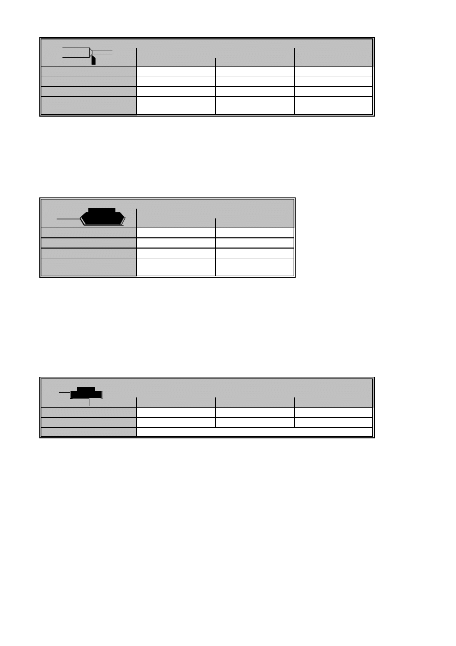
Turning
ORVAR SUPREME
Turning
Cemented carbide
HSS
Roughing
Finishing
Cutting speed, v
c
(m/min)
200-250
250-300
25-30
Feed, f (mm/rev)
0,2-0,4
0,05-0,2
0,05-0,3
Depth of cut, a
p
(mm)
2-4
0,5-2
0,5-3
Suitable grades
P20-P30 coated carbide P10 coated carbide or
cermet
Remarks:
1. Cutting fluid is recommended.
2. For turning with interrupted cut or face turning of large workpieces use a
thougher cemented carbide grade.
Face milling
Face milling
Cemented carbide
Roughing
Finishing
Cutting speed, v
c
(m/min)
200-260
260-300
Feed, f
z
(mm/tooth)
0,2-0,4
0,1-0,2
Depth of cut, a
p
(mm)
2-5
-2
Suitable grades
P20-P40 coated carbide P10-P20 coated carbide
or cermet
Remarks:
1. Use a milling cutter with a positive-negative or positive-positive geometry.
2. Climb milling should generally be used.
3. Milling should generally be done without coolant.
If a high surface finish is required coolant may be used.
4. Cermets can be of use when finishing under stable conditions.
Square shoulder milling
Square shoulder milling with cemented carbide
a
e
= 0.1 x D
a
e
= 0.5 x D
a
e
= 1 x D
Cutting speed, v
c
(m/min)
200-260
190-250
180-240
Feed, f
z
(mm/tooth)
0,25-0,3
0,15-0,2
0,1-0,15
Suitable grades
P15-P40 coated carbide
Remarks:
1. Climb milling should generally be used.
2. Choose the cutter diameter (D) and the radial depth of cut (a
e
) so that at least two cutting edges
are engaged simultaneously.
3. If the machine tool power is inadequate for the data given reduce the depth of cut,
but do not reduce the feed.
2005-01-25
End milling
ORVAR SUPREME
Slot milling
Axial depth of cut, a
p
= 1 x D
Cutter diameter (mm)
3 - 5
5 - 10
10 - 20
20 - 30
30 - 40
Uncoated HSS
1-4)
Cutting speed, v
c
(m/min)
35-40
Feed, f
z
(mm/tooth)
0,01-0,03
0,03-0,04
0,04-0,05
0,05-0,06
0,06-0,09
Coated HSS
1-4)
Cutting speed, v
c
(m/min)
55-60
Feed, f
z
(mm/tooth)
0,02-0,04
0,04-0,05
0,05-0,06
0,06-0,07
0,07-0,10
Solid cemented
Cutting speed, v
c
(m/min)
160-200
carbide
5-8)
Feed, f
z
(mm/tooth)
0,006-0,01
0,01-0,02
0,02-0,04
Indexable insert
6-8)
Cutting speed, v
c
(m/min)
170-230
(cemented carbide
Feed, f
z
(mm/tooth)
0,06-0,08
0,08-0,10
0,10-0,12
inserts)
Suitable grades
P15-P40 coated carbide
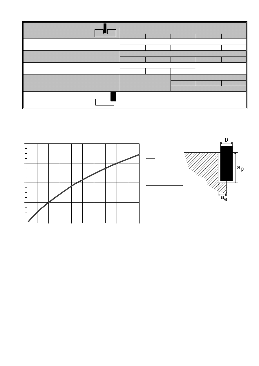
Side milling
For side milling the same cutting speed as for slot milling can
Axial depth of cut, a
p
= 1.5 x D
be used, but the feeds must be adjusted in order to obtain a
suitable average chip thickness.
Correction factor for side milling
Divide the cutter diameter with the radial depth of cut. See in the chart below which correction factor, C
f
, this
corresponds to, and multiply the chosen feed in the table for slot milling with this factor.
Example:
Tool:
CC insert
Cutter diameter:
D = 40 mm
Radial depth of cut:
a
e
= 2 mm
D/a
e
= 40/2 = 20
Feed acc. to table slot milling = 0.11 mm/tooth
Correction factor acc. to chart: C
f
= 2.8
Feed for side milling:
f
z
= 2.8 x 0.11 = 0.31 mm/tooth
Remarks: (slot and side milling)
1. Climb milling is generally recommended.
2. Use a cutter with chipbreaker when side milling with radial depths of cut, a
e
> 0.3 xD.
3. When side milling with small radial depths of cut (a
e
) the cutting speed can be increased by up to 15%.
4. Use liberal amounts of cutting fluid.
5. It is recommended to use a TiCN coated cutter when milling with solid cemented carbide tools.
The axial depth of cut should not exceed the cutter diameter when slot milling.
6. Climb milling is generally recommended.
7. When side milling with small radial depths of cut (a
e
) the cutting speed can be increased by up to 30%.
8. The radial run-out, at the cutting edges, must be small and not exceed 0.03 mm.
1
2
3
4
5
0
10
20
30
40
50
Cutter diameter / Radial depth of cut, D/ae
C
o
rr
ect
ion f
act
or
, C
f
2005-01-25

Drilling
ORVAR SUPREME
Drilling
Drill diameter (mm)
1 - 5
5 - 10
10 - 20
20 - 30
30 - 40
Uncoated HSS
1-2)
Cutting speed, v
c
(m/min)
16-18
Feed, f (mm/rev)
0,05-0,15
0,15-0,25
0,25-0,35
0,35-0,40
0,40-0,45
Coated HSS
1-2)
Cutting speed, v
c
(m/min)
28-30
Feed, f (mm/rev)
0,07-0,18
0,18-0,30
0,30-0,40
0,40-0,45
0,45-0,50
Indexable insert
3-4)
Cutting speed, v
c
(m/min)
220-240
(cem. carbide inserts)
Feed, f (mm/rev)
0,03-0,08
0,08-0,12
Solid cemented
Cutting speed, v
c
(m/min)
130-160
carbide
5-7)
Feed, f (mm/rev)
0,08-0,10
0,10-0,20
0,20-0,30
0,30-0,35
Brazed cemented
Cutting speed, v
c
(m/min)
80-110
carbide
5-7)
Feed, f (mm/rev)
0,15-0,25
0,25-0,35
0,35-0,40
Remarks:
1. The cutting fluid should be ample and directed at the tool.
2. When drilling with short "NC drills" the feed may be increased by up to 20%.
For extra long drills the feed must be decreased.
3. Use insert grades in the range of ISO P20-P30.
Under unstable conditions a tougher carbide grade should be used for the centre position.
4. Use a high cutting fluid pressure and flow rate for a good chip removal.
5. If machining with solid or brazed cemented carbide drills, a rigid set-up and stable working conditions are required.
6. The use of drills with internal cooling channels is recommended.
7. Use a cutting fluid concentration of 15-20 %.
Tapping with HSS
Cutting speed, v
c
= 10-12 m/min
Remarks:
1. Threading compound or cutting oil gives a longer tool life than emulsion.
2. Fluteless tap (non-cutting) is recommended.
2005-01-25
Wyszukiwarka
Podobne podstrony:
orvar supreme eng właściwości
Orvar Supreme Obróbka cieplna
Obróbka wstępna ryb
chrystus jest zyciem mym ENG
PPTOK(13wykł)Uchwyty obróbkowe
wykład+nr+8+ +Obróbki+powierzchniowe
Bezpieczenstwo i higiena pracy podczas obrobki cieplnej
Przegląd rozwiązań konstrukcyjnych wtryskarek (ENG)
W10 Wpływ różnych metod obróbki wstępnej mięsa
5 ObróbkaCiepnaDefinicjeSem2010
Obróbka ręczna Piłowanie Górecki
Assembler ENG
Obróbka plastyczna metali obejmuje
Frequenzimetro eng 2003
24 Wykonywanie prac z zakresu obróbki ręcznej
PM [R2] Sylabus ENG
więcej podobnych podstron